WO2020003535A1 - Resin molded article and method for producing resin molded article - Google Patents
Resin molded article and method for producing resin molded article Download PDFInfo
- Publication number
- WO2020003535A1 WO2020003535A1 PCT/JP2018/024936 JP2018024936W WO2020003535A1 WO 2020003535 A1 WO2020003535 A1 WO 2020003535A1 JP 2018024936 W JP2018024936 W JP 2018024936W WO 2020003535 A1 WO2020003535 A1 WO 2020003535A1
- Authority
- WO
- WIPO (PCT)
- Prior art keywords
- rib
- resin molded
- resin
- molded product
- groove
- Prior art date
Links
Images


Classifications
-
- B—PERFORMING OPERATIONS; TRANSPORTING
- B29—WORKING OF PLASTICS; WORKING OF SUBSTANCES IN A PLASTIC STATE IN GENERAL
- B29C—SHAPING OR JOINING OF PLASTICS; SHAPING OF MATERIAL IN A PLASTIC STATE, NOT OTHERWISE PROVIDED FOR; AFTER-TREATMENT OF THE SHAPED PRODUCTS, e.g. REPAIRING
- B29C45/00—Injection moulding, i.e. forcing the required volume of moulding material through a nozzle into a closed mould; Apparatus therefor
- B29C45/0046—Details relating to the filling pattern or flow paths or flow characteristics of moulding material in the mould cavity
-
- B—PERFORMING OPERATIONS; TRANSPORTING
- B29—WORKING OF PLASTICS; WORKING OF SUBSTANCES IN A PLASTIC STATE IN GENERAL
- B29C—SHAPING OR JOINING OF PLASTICS; SHAPING OF MATERIAL IN A PLASTIC STATE, NOT OTHERWISE PROVIDED FOR; AFTER-TREATMENT OF THE SHAPED PRODUCTS, e.g. REPAIRING
- B29C45/00—Injection moulding, i.e. forcing the required volume of moulding material through a nozzle into a closed mould; Apparatus therefor
- B29C45/0025—Preventing defects on the moulded article, e.g. weld lines, shrinkage marks
-
- B—PERFORMING OPERATIONS; TRANSPORTING
- B60—VEHICLES IN GENERAL
- B60R—VEHICLES, VEHICLE FITTINGS, OR VEHICLE PARTS, NOT OTHERWISE PROVIDED FOR
- B60R13/00—Elements for body-finishing, identifying, or decorating; Arrangements or adaptations for advertising purposes
- B60R13/04—External Ornamental or guard strips; Ornamental inscriptive devices thereon
-
- B—PERFORMING OPERATIONS; TRANSPORTING
- B29—WORKING OF PLASTICS; WORKING OF SUBSTANCES IN A PLASTIC STATE IN GENERAL
- B29C—SHAPING OR JOINING OF PLASTICS; SHAPING OF MATERIAL IN A PLASTIC STATE, NOT OTHERWISE PROVIDED FOR; AFTER-TREATMENT OF THE SHAPED PRODUCTS, e.g. REPAIRING
- B29C45/00—Injection moulding, i.e. forcing the required volume of moulding material through a nozzle into a closed mould; Apparatus therefor
- B29C45/0025—Preventing defects on the moulded article, e.g. weld lines, shrinkage marks
- B29C2045/0043—Preventing defects on the moulded article, e.g. weld lines, shrinkage marks preventing shrinkage by reducing the wall thickness of the moulded article
-
- B—PERFORMING OPERATIONS; TRANSPORTING
- B29—WORKING OF PLASTICS; WORKING OF SUBSTANCES IN A PLASTIC STATE IN GENERAL
- B29C—SHAPING OR JOINING OF PLASTICS; SHAPING OF MATERIAL IN A PLASTIC STATE, NOT OTHERWISE PROVIDED FOR; AFTER-TREATMENT OF THE SHAPED PRODUCTS, e.g. REPAIRING
- B29C33/00—Moulds or cores; Details thereof or accessories therefor
- B29C33/42—Moulds or cores; Details thereof or accessories therefor characterised by the shape of the moulding surface, e.g. ribs or grooves
Abstract
A resin molded article which is provided with a main body and a rib that is integrally molded with the main body, and which is configured such that the rib comprises a rib A that is provided in a direction which extends along the flowing direction of the resin of the main body and a rib B that is provided in a direction which intersects with the flowing direction so as to be positioned in the upstream of the rib A when viewed from the flowing direction.
Description
本発明は、樹脂成形品及び樹脂成形品の製造方法に関する。
The present invention relates to a resin molded product and a method for producing the resin molded product.
近年、自動車の軽量化を目的として、内外装用の部品において金属部材から樹脂成形品への置き換えが進んでいる。これらの樹脂成形品は、車体又は車体関連部材への取付け、強度の確保等を目的として、リブと呼ばれる突起が外側から見えない場所に設けられている。
In recent years, for the purpose of reducing the weight of automobiles, the replacement of metal members with resin molded products in interior and exterior parts has been progressing. These resin molded products are provided at locations where protrusions called ribs are not visible from the outside for the purpose of mounting to a vehicle body or a vehicle body-related member, securing strength, and the like.
リブを備える樹脂成形品としては、射出成形により本体と一体的にリブを形成したものが知られている(例えば、特開2012-188010号公報参照)。このような樹脂成形品は、樹脂成形品のリブが設けられる位置にリブの形状に相当する溝が設けられた金型に樹脂を注入することで製造される。
樹脂 As a resin molded product having a rib, a resin molded product in which a rib is formed integrally with a main body by injection molding is known (for example, see JP-A-2012-188010). Such a resin molded product is manufactured by injecting a resin into a mold provided with a groove corresponding to the shape of the rib at a position where the rib of the resin molded product is provided.
近年、軽量化の観点から樹脂成形品の薄型化が進んでいる。これに伴い、裏側にリブが設けられている樹脂成形品を外側から観察したとき、リブに相当する箇所が周囲と異なって観察され、外観が損なわれるという問題が生じている。その理由は必ずしも明らかではないが、以下のように推測される。
Recently, resin molded products are becoming thinner from the viewpoint of weight reduction. Accordingly, when the resin molded product having the ribs on the back side is observed from the outside, a portion corresponding to the rib is observed differently from the surroundings, causing a problem that the appearance is impaired. The reason is not necessarily clear, but is presumed as follows.
本体に一体的に成形されたリブを備える樹脂成形品は一般に、リブに相当する形状の溝が内壁に設けられた金型に原料となる樹脂を充填することによって作製される。樹脂は、金型に設けられた注入口(ゲート)から供給され、所定の方向に沿って金型内を流動する。このとき、リブに相当する溝が金型の内壁に設けられていると、金型の溝の上を流動する樹脂は溝の内部を埋めるような挙動を示す。その結果、金型の内部では、溝の上を流動する樹脂と、溝の周囲を流動する樹脂との間で流動速度に差が生じる。この流動速度の差に起因して、樹脂成形品の表面に樹脂の流動跡(フローマーク)が発現し、外観に影響を及ぼすと考えられる。
樹脂 Resin molded articles provided with ribs integrally formed on the main body are generally produced by filling a resin as a raw material into a mold provided with a groove having a shape corresponding to the rib on the inner wall. The resin is supplied from an injection port (gate) provided in the mold, and flows in the mold along a predetermined direction. At this time, if the groove corresponding to the rib is provided on the inner wall of the mold, the resin flowing over the groove of the mold behaves like filling the inside of the groove. As a result, inside the mold, there is a difference in flow velocity between the resin flowing over the groove and the resin flowing around the groove. It is considered that a flow mark (flow mark) of the resin appears on the surface of the resin molded article due to the difference in the flow speed, which affects the appearance.
本発明者らの検討の結果、樹脂成形品の表面に生じるフローマークの発現の程度は、樹脂成形品の本体と一体的に設けられたリブの方向と、樹脂成形品を作製する際の樹脂の流動方向とがなす角度と関係していることがわかった。
As a result of the study by the present inventors, the degree of the appearance of flow marks generated on the surface of the resin molded product depends on the direction of the ribs provided integrally with the main body of the resin molded product, and the resin at the time of producing the resin molded product. It was found that it was related to the angle formed by the flow direction of the particles.
すなわち、リブの方向が金型内に供給された樹脂の流動方向に沿っている(リブの方向と樹脂の流動方向とがなす角度が小さい)場合は、リブの方向が金型内に供給された樹脂の流動方向と交わっている(リブの方向と樹脂の流動方向とがなす角度が大きい)場合に比べ、樹脂成形品の表面に生じるフローマークの発現の程度が大きく、外観に与える影響が大きいことがわかった。
That is, when the direction of the rib is along the flow direction of the resin supplied into the mold (the angle between the direction of the rib and the flow direction of the resin is small), the direction of the rib is supplied into the mold. Compared to the case where the flow direction of the resin crosses (the angle between the direction of the rib and the flow direction of the resin is large), the degree of appearance of the flow mark generated on the surface of the resin molded product is large, and the effect on the appearance is reduced. It turned out to be big.
上記事情を考慮すると、樹脂成形品の外観を良好に維持する観点からは、本体に設けられたすべてのリブを樹脂の流動方向と交わる方向に配置することが有効と考えられる。しかしながら、すべてのリブを樹脂の流動方向と交わる方向に配置すると、リブ自体又は樹脂成形品全体の強度が充分に確保されないおそれがある。従って、必要な強度を確保する観点からは、樹脂成形品に設けられるリブの少なくとも一部を樹脂の流動方向に沿った方向に配置することが望ましい。
と Considering the above circumstances, it is considered effective to arrange all the ribs provided on the main body in a direction intersecting with the flow direction of the resin from the viewpoint of maintaining the good appearance of the resin molded product. However, if all the ribs are arranged in a direction intersecting the flow direction of the resin, there is a possibility that the strength of the ribs themselves or the entire resin molded product is not sufficiently secured. Therefore, from the viewpoint of securing necessary strength, it is desirable to arrange at least a part of the rib provided on the resin molded product in a direction along the flow direction of the resin.
本発明者らは上記事情に鑑み、必要な強度を確保しながら良好な外観が維持される樹脂成形品及びその製造方法を提供することを課題とする。
In view of the above circumstances, the inventors of the present invention have an object to provide a resin molded product which maintains a required appearance and maintains a good appearance, and a method for producing the same.
課題を解決するための具体的手段には、以下の態様が含まれる。
<1>本体と、前記本体と一体的に成形されたリブと、を備え、前記リブは、前記本体の樹脂の流動方向に沿った方向に設けられたリブAと、前記流動方向にみて前記リブAの上流側に、前記流動方向と交わる方向に設けられたリブBと、を含む、樹脂成形品。
<2>前記リブAが前記リブBと接しているか、前記リブAと前記リブBとの距離が30mm以下である、<1>に記載の樹脂成形品。
<3>前記リブAの幅が0.5mm~2mmである、<1>又は<2>に記載の樹脂成形品。
<4>少なくとも一部が発泡した樹脂で形成されている、<1>~<3>のいずれか1項に記載の樹脂成形品。
<5>自動車の内外装部品である、<1>~<4>のいずれか1項に記載の樹脂成形品。
<6>内壁に溝が設けられた金型に樹脂を供給する工程を備え、前記溝は、前記金型に供給される樹脂の流動方向に沿った方向に設けられた溝Aと、前記流動方向にみて前記溝Aの上流側に、前記流動方向と交わる方向に設けられた溝Bと、を含む、樹脂成形品の製造方法。
<7>前記溝Aが前記溝Bと接しているか、前記溝Aと前記溝Bとの距離が30mm以下である、<6>に記載の樹脂成形品の製造方法。
<8>前記溝Aの幅が0.5mm~2mmである、<6>又は<7>に記載の樹脂成形品の製造方法。
<9>射出成形法により行われる、<6>~<8>のいずれか1項に記載の樹脂成形品の製造方法。
<10>前記樹脂成形品は自動車の内外装部品である、<6>~<9>のいずれか1項に記載の樹脂成形品の製造方法。 Specific means for solving the problems include the following aspects.
<1> a main body, and a rib formed integrally with the main body, wherein the rib is provided with a rib A provided in a direction along a resin flowing direction of the main body, and a rib A as viewed in the flowing direction. A resin molded product, comprising: a rib B provided upstream of the rib A in a direction intersecting the flow direction.
<2> The resin molded product according to <1>, wherein the rib A is in contact with the rib B, or a distance between the rib A and the rib B is 30 mm or less.
<3> The resin molded product according to <1> or <2>, wherein the width of the rib A is 0.5 mm to 2 mm.
<4> The resin molded product according to any one of <1> to <3>, wherein at least a part of the resin molded product is formed of a foamed resin.
<5> The resin molded product according to any one of <1> to <4>, which is an interior / exterior part of an automobile.
<6> a step of supplying a resin to a mold provided with a groove on the inner wall, wherein the groove is provided with a groove A provided in a direction along a flow direction of the resin supplied to the mold; And a groove B provided on the upstream side of the groove A in a direction intersecting with the flow direction.
<7> The method for producing a resin molded product according to <6>, wherein the groove A is in contact with the groove B, or a distance between the groove A and the groove B is 30 mm or less.
<8> The method for producing a resin molded product according to <6> or <7>, wherein the width of the groove A is 0.5 mm to 2 mm.
<9> The method for producing a resin molded product according to any one of <6> to <8>, which is performed by an injection molding method.
<10> The method for producing a resin molded product according to any one of <6> to <9>, wherein the resin molded product is an interior / exterior component of an automobile.
本発明によれば、必要な強度を確保しながら良好な外観が維持される樹脂成形品及びその製造方法が提供される。
According to the present invention, there is provided a resin molded product in which a good appearance is maintained while securing necessary strength, and a method for producing the same.
以下、本発明を実施するための形態について詳細に説明する。但し、本発明は以下の実施形態に限定されるものではない。以下の実施形態において、その構成要素(要素ステップ等も含む)は、特に明示した場合を除き、必須ではない。数値及びその範囲についても同様であり、本発明を制限するものではない。
本開示において「工程」との語には、他の工程から独立した工程に加え、他の工程と明確に区別できない場合であってもその工程の目的が達成されれば、当該工程も含まれる。
本開示において「~」を用いて示された数値範囲には、「~」の前後に記載される数値がそれぞれ最小値及び最大値として含まれる。
本開示に段階的に記載されている数値範囲において、一つの数値範囲で記載された上限値又は下限値は、他の段階的な記載の数値範囲の上限値又は下限値に置き換えてもよい。また、本開示に記載されている数値範囲において、その数値範囲の上限値又は下限値は、実施例に示されている値に置き換えてもよい。 Hereinafter, embodiments for carrying out the present invention will be described in detail. However, the present invention is not limited to the following embodiments. In the following embodiments, the constituent elements (including element steps and the like) are not essential unless otherwise specified. The same applies to numerical values and their ranges, and does not limit the present invention.
In the present disclosure, the term “step” includes, in addition to a step independent of other steps, even if the purpose of the step is achieved even if it cannot be clearly distinguished from the other steps, the step is also included. .
In the present disclosure, the numerical ranges indicated by using “to” include the numerical values described before and after “to” as the minimum value and the maximum value, respectively.
In the numerical ranges described in stages in the present disclosure, the upper limit or lower limit described in one numerical range may be replaced with the upper limit or lower limit of another numerical range described in stages. Further, in the numerical range described in the present disclosure, the upper limit or the lower limit of the numerical range may be replaced with the value shown in the embodiment.
<樹脂成形品>
本開示の樹脂成形品は、本体と、前記本体と一体的に成形されたリブと、を備え、前記リブは、前記本体の樹脂の流動方向に沿った方向に設けられたリブAと、前記流動方向にみて前記リブAの上流側に、前記流動方向と交わる方向に設けられたリブBと、を含む、樹脂成形品である。 <Resin molded product>
The resin molded product of the present disclosure includes a main body, and a rib formed integrally with the main body, wherein the rib has a rib A provided in a direction along a resin flowing direction of the main body; It is a resin molded product including: a rib B provided in a direction intersecting the flow direction, on an upstream side of the rib A in the flow direction.
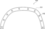
図1は、本開示の樹脂成形品の一例を模式的に示す全体図であり、樹脂成形品のリブが設けられた側の面を観察したときの図である。図1に示す樹脂成形品100は、本体101と、本体101と一体的に成形されたリブを含み、車体に取り付けるための部品であるクリップ座102とを備えている。
図1に示す樹脂成形品は、自動車の外装部品であるアーチモールの形状を有しているが、本開示の樹脂成形品はこれに制限されない。また、図1に示す樹脂成形品100では、リブがクリップ座を構成しているが、本開示のリブはこれに制限されない。 FIG. 1 is an overall view schematically illustrating an example of a resin molded product according to the present disclosure, and is a diagram when a surface of a resin molded product on a side on which ribs are provided is observed. A resin moldedproduct 100 shown in FIG. 1 includes a main body 101, and a clip seat 102 that includes a rib formed integrally with the main body 101 and is a component to be attached to a vehicle body.
Although the resin molded product shown in FIG. 1 has the shape of an arch molding, which is an exterior part of an automobile, the resin molded product of the present disclosure is not limited thereto. Further, in the resin moldedproduct 100 shown in FIG. 1, the rib constitutes the clip seat, but the rib of the present disclosure is not limited to this.
図1に示す樹脂成形品は、自動車の外装部品であるアーチモールの形状を有しているが、本開示の樹脂成形品はこれに制限されない。また、図1に示す樹脂成形品100では、リブがクリップ座を構成しているが、本開示のリブはこれに制限されない。 FIG. 1 is an overall view schematically illustrating an example of a resin molded product according to the present disclosure, and is a diagram when a surface of a resin molded product on a side on which ribs are provided is observed. A resin molded
Although the resin molded product shown in FIG. 1 has the shape of an arch molding, which is an exterior part of an automobile, the resin molded product of the present disclosure is not limited thereto. Further, in the resin molded
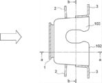
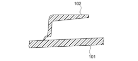
図2Aは、樹脂成形品100におけるクリップ座102の平面図である。図2Aに示すクリップ座102は、クリップ座本体103と、クリップ座本体103の側面に配置されて本体101とクリップ座本体103とを連結するリブ1~3とを備えている。図2Bは図2Aのa-a線におけるクリップ座102と本体101の断面図であり、図2Cは図2Aのb-b線におけるクリップ座102と本体101の断面図であり、図2Dは図2Aに示すクリップ座の斜視図である。
FIG. 2A is a plan view of the clip seat 102 in the resin molded product 100. FIG. The clip seat 102 shown in FIG. 2A includes a clip seat main body 103 and ribs 1 to 3 that are arranged on side surfaces of the clip seat main body 103 and connect the main body 101 and the clip seat main body 103. 2B is a cross-sectional view of the clip seat 102 and the main body 101 taken along the line aa of FIG. 2A, FIG. 2C is a cross-sectional view of the clip seat 102 and the main body 101 taken along the line bb of FIG. 2A, and FIG. It is a perspective view of the clip seat shown to 2A.
図2Aに示すように、クリップ座102では、樹脂の流動方向(ブロック矢印で示す)に沿った方向に設けられたリブ3の一部(リブAに相当)の上流側に、樹脂の流動方向と交わる方向に設けられたリブ2(リブBに相当)が存在する。
As shown in FIG. 2A, in the clip seat 102, the resin flow direction is located upstream of a part (corresponding to rib A) of the rib 3 provided in the direction along the resin flow direction (indicated by a block arrow). There is a rib 2 (corresponding to a rib B) provided in a direction intersecting with.
図2Aに示す樹脂成形品は、クリップ座102が設けられた側と逆側から観察したときに、クリップ座102に対応する位置にフローマークが目立たず、良好な外見が維持される。その理由は必ずしも明らかではないが、以下のように推測される。
2A, when viewed from the side opposite to the side where the clip seat 102 is provided, the flow mark is not conspicuous at the position corresponding to the clip seat 102, and the resin molded article shown in FIG. 2A maintains a good appearance. The reason is not necessarily clear, but is presumed as follows.
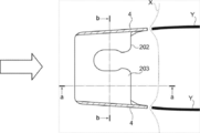
図3Aは、従来のクリップ座202の平面図である。図3Aに示すクリップ座202では、クリップ座本体203の側面がリブ4としての役割を果たし、本体201とクリップ座本体203とを連結している。を備えている。図3Bは図3Aのa-a線におけるクリップ座202と本体201の断面図であり、図3Cは図3Aのb-b線におけるクリップ座202と本体201の断面図である。
FIG. 3A is a plan view of a conventional clip seat 202. In the clip seat 202 shown in FIG. 3A, the side surface of the clip seat main body 203 serves as the rib 4 and connects the main body 201 and the clip seat main body 203. It has. 3B is a cross-sectional view of the clip seat 202 and the main body 201 taken along the line aa of FIG. 3A, and FIG. 3C is a cross-sectional view of the clip seat 202 and the main body 201 taken along the line bb of FIG. 3A.
図3Aに示すように、従来のクリップ座202では、樹脂の流動方向(ブロック矢印で示す)に沿った方向に設けられたリブ4(リブAに相当)の上流側に、樹脂の流動方向と交わる方向に設けられたリブが存在しない。この場合、金型内を流動する樹脂の状態を観察すると、流動する樹脂の先端(点線Xで示す)においてリブ4に相当する部分に凹みが生じていることからわかるように、樹脂の流動速度が周囲よりも遅くなる。その結果、樹脂の流動速度の差に起因したフローマーク(実線Yで示す)がリブ4の下流側に生じると考えられる。
As shown in FIG. 3A, in the conventional clip seat 202, the resin flow direction and the rib 4 (corresponding to rib A) provided in the direction along the resin flow direction (indicated by block arrows) are provided. There are no ribs provided in the intersecting direction. In this case, when observing the state of the resin flowing in the mold, it can be seen from the fact that a dent is formed in the portion corresponding to the rib 4 at the tip (indicated by the dotted line X) of the flowing resin. Is slower than the surroundings. As a result, it is considered that a flow mark (indicated by a solid line Y) due to the difference in the flow speed of the resin is generated on the downstream side of the rib 4.
これに対し、図2Aに示すクリップ座102を備える樹脂成形品は、金型内を流動する樹脂の状態を観察すると、流動する樹脂の先端において図3Aに示すような凹みが生じず、樹脂の流動速度が一定に維持される。その結果、図3Aに示すようなフローマークがリブ3の下流側に生じにくく、外観が良好に維持されると考えられる。
On the other hand, when observing the state of the resin flowing in the mold, the resin molded product provided with the clip seat 102 shown in FIG. 2A does not have a dent as shown in FIG. The flow velocity is kept constant. As a result, a flow mark as shown in FIG. 3A is unlikely to be generated on the downstream side of the rib 3, and it is considered that the appearance is favorably maintained.
本開示の樹脂成形品において「樹脂の流動方向」は、樹脂成形品の作製に用いた樹脂が金型内を流動する方向を意味する。樹脂成形品における樹脂の流動方向は、例えば、樹脂成形品に生じた金型のゲート跡の位置によって確認することができる。あるいは、樹脂成形品の表面又は断面の状態を観察することによって確認することができる。
に お い て In the resin molded product of the present disclosure, the “flow direction of the resin” means the direction in which the resin used for producing the resin molded product flows in the mold. The flow direction of the resin in the resin molded product can be confirmed, for example, by the position of the gate mark of the mold generated in the resin molded product. Alternatively, it can be confirmed by observing the state of the surface or cross section of the resin molded product.
本開示において「樹脂の流動方向」は、個々のリブに相当する溝の上を通過するときの樹脂の流動方向を意味し、リブ間で異なっていてもよい。したがって、樹脂成形品における樹脂の流動方向は、一方向のみでも複数方向の組み合わせであってもよい。
に お い て In the present disclosure, “flow direction of resin” means the flow direction of resin when passing over grooves corresponding to individual ribs, and may differ between ribs. Therefore, the flow direction of the resin in the resin molded article may be only one direction or a combination of a plurality of directions.
本開示の樹脂成形品において「樹脂の流動方向に沿った方向に設けられたリブA」は、樹脂の流動方向となす角度が0°以上40°未満の方向に沿って設けられたリブを意味し、「流動方向と交わる方向に設けられたリブB」は、樹脂の流動方向となす角度が60°~90°の方向に沿って設けられたリブを意味する。
In the resin molded product of the present disclosure, “rib A provided in a direction along the resin flow direction” means a rib provided along a direction in which an angle to the flow direction of the resin is 0 ° or more and less than 40 °. The “rib B provided in a direction intersecting with the flow direction” means a rib provided along a direction in which the angle between the resin B and the flow direction is 60 ° to 90 °.
リブAが設けられた方向と樹脂の流動方向とがなす角度は0°~20°であることが好ましく、0°~10°であることがより好ましい。
リブBが設けられた方向と樹脂の流動方向とがなす角度は75°~90°であることが好ましく、80°~90°であることがより好ましい。 The angle between the direction in which the ribs A are provided and the flow direction of the resin is preferably 0 ° to 20 °, and more preferably 0 ° to 10 °.
The angle between the direction in which the ribs B are provided and the flow direction of the resin is preferably 75 ° to 90 °, and more preferably 80 ° to 90 °.
本開示において、リブA及びリブB(以下、あわせてリブともいう)が設けられた方向は、リブの底部(樹脂成形品の本体からリブが立ち上がっている部分)を基準として判断する。例えば、リブの底部の形状が長方形又はそれに準じる形状である場合は、当該形状の長辺に沿った方向をリブが設けられた方向とする。リブの底部の形状が長方形でない場合は、底部の最大径に沿った方向をリブが設けられた方向とする。
In the present disclosure, the direction in which the ribs A and B (hereinafter, also referred to as ribs) are provided is determined based on the bottom of the rib (the portion where the rib rises from the main body of the resin molded product). For example, when the shape of the bottom of the rib is a rectangle or a shape similar thereto, the direction along the long side of the shape is defined as the direction in which the rib is provided. When the shape of the bottom of the rib is not rectangular, the direction along the maximum diameter of the bottom is defined as the direction in which the rib is provided.
リブの底部の形状は、全体が樹脂の流動方向に沿った方向又は樹脂の流動方向に交わる方向を向いているI字型の形状であっても、I字型以外の形状であってもよい。I字型以外の形状としては、異なる方向を向いているI字型の組み合わせ(L字型、十字型等)、I字型の形状とI字型以外の形状の組み合わせ(U字型等)などが挙げられる。リブの底部の形状がI字型と、I字型以外の形状の組み合わせである場合は、I字型の部分が向いている方向をリブが設けられている方向とする。この場合、I字型の部分の長さをリブの長さとし、I字型の部分の幅をリブの幅とする。
The shape of the bottom of the rib may be an I-shaped shape in which the whole faces in a direction along the flow direction of the resin or a direction intersecting the flow direction of the resin, or may be a shape other than the I-shape. . As a shape other than the I-shape, a combination of I-shapes facing in different directions (L-shape, cross shape, etc.), a combination of an I-shape and a shape other than I-shape (U-shape, etc.) And the like. When the shape of the bottom of the rib is a combination of an I-shape and a shape other than the I-shape, the direction in which the I-shape portion faces is the direction in which the rib is provided. In this case, the length of the I-shaped portion is defined as the length of the rib, and the width of the I-shaped portion is defined as the width of the rib.
樹脂成形品において、リブAとリブBとは接していても、離れて位置していてもよい。フローマークの発現を抑制する観点からは、リブAとリブBとは接しているか、リブAとリブBとの距離が30mm以下であることが好ましく、リブAとリブBとは接しているか、リブAとリブBとの距離が10mm以下であることがより好ましい。本開示においてリブAとリブBとの距離とは、リブAと、リブAに最も近いリブBとの距離を意味する。具体的には、リブAの底部の輪郭と、リブAに最も近いリブBの底部の輪郭とを結ぶ線分のうち最も短いものの長さを意味する。
リ ブ In the resin molded product, the rib A and the rib B may be in contact with each other or may be separated from each other. From the viewpoint of suppressing the appearance of the flow mark, the rib A and the rib B are preferably in contact with each other, or the distance between the rib A and the rib B is preferably 30 mm or less. More preferably, the distance between the rib A and the rib B is 10 mm or less. In the present disclosure, the distance between the rib A and the rib B means the distance between the rib A and the rib B closest to the rib A. Specifically, it means the length of the shortest line segment connecting the contour of the bottom of the rib A and the contour of the bottom of the rib B closest to the rib A.
樹脂成形品に設けられるリブAとリブBの数は、特に制限されない。また、1つのリブAに対応するリブBの数は1つであっても複数であってもよく、1つのリブBに対応するリブAの数は1つであっても複数であってもよい。
数 The number of ribs A and ribs B provided on the resin molded product is not particularly limited. The number of ribs B corresponding to one rib A may be one or more, and the number of ribs A corresponding to one rib B may be one or more. Good.
フローマークの発現を抑制する観点からは、リブAの幅は狭いほど好ましい。例えば、リブAの幅は2mm以下であることが好ましく、1.5mm以下であることがより好ましく、1mm以下であることがさらに好ましい。一方、強度を確保する観点からは、リブAの幅は広いほど好ましい。例えば、リブAの幅は0.5mm以上であることが好ましい。
か ら From the viewpoint of suppressing the appearance of the flow mark, the narrower the width of the rib A, the better. For example, the width of the rib A is preferably 2 mm or less, more preferably 1.5 mm or less, and even more preferably 1 mm or less. On the other hand, from the viewpoint of securing the strength, the wider the width of the rib A, the better. For example, the width of the rib A is preferably 0.5 mm or more.
フローマークの発現を抑制する観点からは、リブAの長さは短いほど好ましい。例えば、リブAの長さは100mm以下であることが好ましく、70mm以下であることがより好ましく、50mm以下であることがさらに好ましい。一方、強度を確保する観点からは、リブAの長さは長いほど好ましい。例えば、リブAの長さは2mm以上であることが好ましく、5mm以上であることがより好ましい。
か ら From the viewpoint of suppressing the appearance of the flow mark, the shorter the length of the rib A, the better. For example, the length of the rib A is preferably 100 mm or less, more preferably 70 mm or less, and even more preferably 50 mm or less. On the other hand, from the viewpoint of securing strength, it is preferable that the length of the rib A is longer. For example, the length of the rib A is preferably 2 mm or more, more preferably 5 mm or more.
フローマークの発現を抑制する観点からは、リブAの高さは低いほど好ましい。例えば、リブAの高さは20mm以下であることが好ましく、15mm以下であることがより好ましい。一方、強度を確保する観点からは、リブAの高さは高いほど好ましい。例えば、リブAの高さは1mm以上であることが好ましく、2mm以上であることがより好ましく、5mm以上であることがさらに好ましい。
か ら From the viewpoint of suppressing the appearance of flow marks, the lower the height of the rib A, the better. For example, the height of the rib A is preferably 20 mm or less, and more preferably 15 mm or less. On the other hand, from the viewpoint of ensuring strength, the higher the height of the rib A, the more preferable. For example, the height of the rib A is preferably 1 mm or more, more preferably 2 mm or more, even more preferably 5 mm or more.
樹脂成形品において、リブBは樹脂の流動方向と交わる方向に設けられており、リブB自体に起因するフローマークは発現しにくいため、その形状は特に制限されない。例えば、リブBの長さは、5mm~100mmの範囲内であってもよい。また、リブBの幅は0.5mm~5mmの範囲内であってもよい。
(4) In the resin molded product, the rib B is provided in a direction intersecting with the flow direction of the resin, and the flow mark due to the rib B itself is hardly developed, and thus the shape is not particularly limited. For example, the length of the rib B may be in a range from 5 mm to 100 mm. Further, the width of the rib B may be in the range of 0.5 mm to 5 mm.
樹脂成形品において、リブの設けられる位置は特に制限されない。例えば、車体等への取り付けを目的とする場合は、車体等に取り付けられる場所に設けられる。樹脂成形品の補強を目的とする場合は、補強が必要な場所に設けられる。
位置 In the resin molded product, the position where the rib is provided is not particularly limited. For example, when it is intended to be mounted on a vehicle body or the like, it is provided at a place where it is mounted on the vehicle body or the like. If the purpose is to reinforce the resin molded product, it is provided in a place where reinforcement is required.
樹脂成形品の本体の厚み(厚みが一定でない場合は厚みの最小値)は特に制限されず、樹脂成形品の形状、用途等に応じて選択できる。フローマークの発現を抑制し、かつ強度を確保する観点からは、樹脂成形品の本体は厚いほど好ましい。例えば、本体の厚み(特に、リブが設けられる面の厚み)は1mm以上であることが好ましく、2mm以上であることがより好ましい。一方、軽量化の観点からは、樹脂成形品の本体は薄いほど好ましい。例えば、本体の厚みは4mm以下であることが好ましく、3mm以下であることがより好ましく、2.5mm以下であることがさらに好ましい。
厚 み The thickness of the main body of the resin molded product (the minimum value of the thickness when the thickness is not constant) is not particularly limited, and can be selected according to the shape, application, and the like of the resin molded product. From the viewpoint of suppressing the appearance of the flow mark and securing the strength, it is preferable that the body of the resin molded product is thicker. For example, the thickness of the main body (particularly, the thickness of the surface on which the rib is provided) is preferably 1 mm or more, and more preferably 2 mm or more. On the other hand, from the viewpoint of weight reduction, the thinner the main body of the resin molded product, the better. For example, the thickness of the main body is preferably 4 mm or less, more preferably 3 mm or less, and even more preferably 2.5 mm or less.
樹脂成形品の大きさは、特に制限されない。強度を維持しつつ薄型化を実現し、かつ外見が良好に維持されるという効果を充分に発揮する観点からは、例えば、主面(面積が最大となる面)の面積が180cm2以上であってもよい。
The size of the resin molded product is not particularly limited. From the viewpoint of realizing the effect of realizing the thinning while maintaining the strength and maintaining the good appearance, for example, the area of the main surface (the surface having the largest area) is 180 cm 2 or more. You may.
樹脂成形品では、設けられるすべてのリブが上述したリブAとリブBの条件を満たすものであってもよく、一部のリブが上述したリブAとリブBの条件を満たすものであってもよい。例えば、樹脂成形品の外観が重視される部分に設けられるリブが上述したリブAとリブBの条件を満たすものであってもよい。
In the resin molded product, all the provided ribs may satisfy the above-described conditions of the ribs A and B, or some of the ribs may satisfy the above-described conditions of the ribs A and B. Good. For example, the rib provided in the portion where the appearance of the resin molded product is important may satisfy the above-described conditions of the rib A and the rib B.
樹脂成形品は、少なくとも一部が発泡した樹脂で形成されていてもよい。樹脂成形品の少なくとも一部が発泡した樹脂で形成されることで、樹脂成形品が発泡していない樹脂で形成されている場合に比べ、同じ厚さでも樹脂成形品を軽量化することができる。
The resin molded article may be formed at least in part from a foamed resin. Since at least a part of the resin molded product is formed of the foamed resin, the weight of the resin molded product can be reduced even with the same thickness as compared with the case where the resin molded product is formed of the non-foamed resin. .
樹脂成形品の少なくとも一部が発泡した樹脂で形成されている場合は、例えば、樹脂成形品の表面に近い部分が発泡していない樹脂(スキン層)で形成され、内部が発泡した樹脂で形成されていてもよい。
When at least a part of the resin molded product is formed of foamed resin, for example, a portion close to the surface of the resin molded product is formed of non-foamed resin (skin layer), and the inside is formed of foamed resin. It may be.
樹脂成形品の少なくとも一部が発泡した樹脂で形成されている場合、その製造方法は特に制限されない。例えば、可動側金型と、固定側金型とからなる一対の金型の間の空隙(キャビティ)に発泡剤を含む樹脂材料を充填した後に、可動側金型を固定側金型から離れる方向に移動(コアバック)させて樹脂材料を充填した空隙の容積を増大させることで樹脂材料を発泡させ、この状態で冷却することにより、発泡した樹脂の成形体である樹脂成形品を製造することができる(射出発泡成形)。この際、所定の位置にリブの形状に相当する溝を金型に設けることで、樹脂材料の本体の表面にリブを一体的に成形することができる。また、可動側金型の移動距離を調節することで、所望の厚さの樹脂成形品を製造することができる。
(4) When at least a part of the resin molded product is formed of a foamed resin, the production method is not particularly limited. For example, after filling a cavity (cavity) between a pair of molds including a movable mold and a fixed mold with a resin material containing a foaming agent, the movable mold is separated from the fixed mold. Moving the resin material (core back) to increase the volume of the void filled with the resin material, thereby foaming the resin material, and cooling in this state to produce a resin molded product that is a molded product of the foamed resin. (Injection foam molding). At this time, by providing a groove corresponding to the shape of the rib at a predetermined position in the mold, the rib can be integrally formed on the surface of the resin material main body. Further, by adjusting the moving distance of the movable mold, a resin molded product having a desired thickness can be manufactured.
樹脂成形品の製造に用いる樹脂は、特に制限されない。例えば、射出成形に一般的に使用される熱可塑性樹脂から選択できる。具体的には、ポリエチレン系樹脂、ポリプロピレン系樹脂、複合ポリプロピレン系樹脂、ポリスチレン系樹脂、ポリエチレンテレフタレート系樹脂、ポリビニルアルコール系樹脂、塩化ビニル系樹脂、アイオノマー系樹脂、ポリアミド系樹脂、アクリロニトリル・ブタジエン・スチレン共重合樹脂及びポリカーボネート系樹脂が挙げられる。この中でも、ポリプロピレン系樹脂、複合ポリプロピレン系樹脂及びアクリロニトリル・ブタジエン・スチレン共重合樹脂からなる群より選択される少なくとも1種が好ましい。樹脂成形品の製造に用いる樹脂は、1種のみであっても2種以上であってもよい。
樹脂 The resin used for manufacturing the resin molded product is not particularly limited. For example, it can be selected from thermoplastic resins commonly used for injection molding. Specifically, polyethylene resin, polypropylene resin, composite polypropylene resin, polystyrene resin, polyethylene terephthalate resin, polyvinyl alcohol resin, vinyl chloride resin, ionomer resin, polyamide resin, acrylonitrile butadiene styrene Copolymer resins and polycarbonate resins are exemplified. Among them, at least one selected from the group consisting of a polypropylene resin, a composite polypropylene resin, and an acrylonitrile-butadiene-styrene copolymer resin is preferable. The resin used in the production of the resin molded article may be only one kind or two or more kinds.
樹脂成形品の製造に発泡剤を用いる場合、発泡剤としては、アゾジカルボンアミド等の有機発泡剤、炭酸水素ナトリウム(別名、重炭酸ナトリウム、重曹)等の無機発泡剤などが挙げられる。現在、自動車用内装部品の発泡成形では、発泡剤として無機系の炭酸水素ナトリウムが主に用いられているが、塗膜性能(耐温水性等)の向上の観点からは、有機発泡剤が好ましい。
(4) When a foaming agent is used in the production of a resin molded product, examples of the foaming agent include an organic foaming agent such as azodicarbonamide and an inorganic foaming agent such as sodium hydrogen carbonate (also known as sodium bicarbonate and sodium bicarbonate). At present, in the foam molding of interior parts for automobiles, inorganic sodium hydrogen carbonate is mainly used as a foaming agent, but from the viewpoint of improving coating film performance (such as hot water resistance), an organic foaming agent is preferable. .
有機発泡剤としては、アゾジカルボンアミド(ADCA)、N,N-ジニトロソペンタメチレンテトラミン(DPT)、4,4-オキシビスベンゼンスルホニルヒドラジド(OBSH)、ヒドラゾジカルボンアミド(HDCA)等が挙げられ、アゾジカルボンアミド(ADCA)が好ましい。
Examples of the organic foaming agent include azodicarbonamide (ADCA), N, N-dinitrosopentamethylenetetramine (DPT), 4,4-oxybisbenzenesulfonylhydrazide (OBSH), and hydrazodicarbonamide (HDCA). And azodicarbonamide (ADCA) are preferred.
本開示の樹脂成形品は、種々の用途に用いることができる。特に、樹脂成形品の外観が重視される用途、例えば自動車の内外装部品に好適に用いることができる。自動車の内外装部品としては、アーチモール、サイドモール、ロッカーモール、バンパー等が挙げられる。
樹脂 The resin molded product of the present disclosure can be used for various applications. In particular, it can be suitably used for applications where the appearance of a resin molded product is important, for example, interior and exterior parts of automobiles. As interior and exterior parts of an automobile, an arch molding, a side molding, a rocker molding, a bumper, and the like can be given.
<樹脂成形品の製造方法>
本開示の樹脂成形品の製造方法は、内壁に溝が設けられた金型に樹脂を供給する工程を備え、前記溝は、前記金型に供給される樹脂の流動方向に沿った方向に設けられた溝Aと、前記流動方向にみて前記溝Aの上流側に、前記流動方向と交わる方向に設けられた溝Bと、を含む、樹脂成形品の製造方法である。 <Production method of resin molded product>
The method of manufacturing a resin molded product according to the present disclosure includes a step of supplying a resin to a mold having a groove provided on an inner wall, wherein the groove is provided in a direction along a flow direction of the resin supplied to the mold. A groove A provided on the upstream side of the groove A as viewed in the flow direction, and a groove B provided in a direction intersecting the flow direction.
上記方法により製造される樹脂成形品は、本体と一体的に成形され、かつ金型の内壁に設けられた溝の形状に対応する形状のリブを備える。すなわちこの樹脂成形品が有するリブは、上述した本開示の樹脂成形品におけるリブAとリブBの条件を満たす。このため、上記方法により製造される樹脂成形品は、リブが設けられた面と逆の面におけるフローマークの発現が抑制され、良好な外観が維持される。
樹脂 The resin molded product manufactured by the above method is provided integrally with the main body and has a rib having a shape corresponding to the shape of the groove provided on the inner wall of the mold. That is, the rib of the resin molded product satisfies the conditions of the rib A and the rib B in the resin molded product of the present disclosure described above. Therefore, in the resin molded product manufactured by the above method, the appearance of flow marks on the surface opposite to the surface on which the ribs are provided is suppressed, and a good appearance is maintained.
上記方法により製造される樹脂成形品の詳細及び好ましい態様としては、必要に応じて「リブ」を「溝」と読み替えたうえで、上述した樹脂成形品及びリブの詳細及び好ましい態様を参照することができる。
For details and preferred embodiments of the resin molded product manufactured by the above method, refer to the above-described details and preferred embodiments of the resin molded product and the rib after replacing “rib” with “groove” as necessary. Can be.
上記方法を実施する方法は、特に制限されない。例えば、樹脂成形品の製造方法として一般的な射出成形法であってもよい。また、上述したような少なくとも一部が発泡した樹脂となるような製造方法であってもよい。
方法 The method for implementing the above method is not particularly limited. For example, a general injection molding method may be used as a method for manufacturing a resin molded product. Further, a manufacturing method in which at least a part of the resin is a foamed resin as described above may be used.
以下、本発明を実施するための形態について詳細に説明する。但し、本発明は以下の実施形態に限定されるものではない。以下の実施形態において、その構成要素(要素ステップ等も含む)は、特に明示した場合を除き、必須ではない。数値及びその範囲についても同様であり、本発明を制限するものではない。
Hereinafter, embodiments for carrying out the present invention will be described in detail. However, the present invention is not limited to the following embodiments. In the following embodiments, the constituent elements (including element steps and the like) are not essential unless otherwise specified. The same applies to numerical values and ranges thereof, and does not limit the present invention.
ポリプロピレン系樹脂100質量部と、発泡剤としてアゾジカルボンアミド(ADCA)2質量部を混合して作製した樹脂材料を用いて、射出発泡成形により樹脂成形品を作製した。金型としては、内壁に図2Aに示すクリップ座102と、図3Aに示すクリップ座202に相当する形状の溝が設けられているものを使用した。
A resin molded product was produced by injection foam molding using a resin material produced by mixing 100 parts by mass of a polypropylene resin and 2 parts by mass of azodicarbonamide (ADCA) as a foaming agent. As the mold, one having a groove corresponding to the clip seat 102 shown in FIG. 2A and the clip seat 202 shown in FIG. 3A was provided on the inner wall.
上記金型と樹脂材料を用いて、樹脂成形品を作製した。この際、溝の上を通過するときの樹脂材料の流動方向が図2A及び図3Aに示す矢印の方向になるように、金型に設けられたゲートから樹脂材料を供給した。成形条件は、金型温度を50℃、シリンダ温度を220℃、冷却時間を15秒、射出時の樹脂材料温度を220℃とした。
樹脂 A resin molded product was produced using the above-mentioned mold and resin material. At this time, the resin material was supplied from the gate provided in the mold so that the flow direction of the resin material when passing over the groove was in the direction of the arrow shown in FIGS. 2A and 3A. The molding conditions were a mold temperature of 50 ° C., a cylinder temperature of 220 ° C., a cooling time of 15 seconds, and a resin material temperature at the time of injection of 220 ° C.
作製した樹脂成形品の本体のクリップ座が設けられた面の厚みは、3mmとした。また、クリップ座102におけるリブ1の幅を0.5mmとし、リブ2の樹脂の流動方向に沿った部分の幅を0.9mmとし、リブ2の樹脂の流動方向に交わる部分の幅を0.6mmとし、リブ3の幅を0.9mmとし、クリップ座202におけるリブ4の幅を0.8mmとした。
厚 み The thickness of the surface of the produced resin molded product on which the clip seat was provided was 3 mm. The width of the rib 1 in the clip seat 102 is 0.5 mm, the width of a portion of the rib 2 along the flow direction of the resin is 0.9 mm, and the width of a portion of the rib 2 intersecting the flow direction of the resin is 0.1 mm. 6 mm, the width of the rib 3 was 0.9 mm, and the width of the rib 4 in the clip seat 202 was 0.8 mm.
作製した樹脂成形品のクリップ座201、202が設けられた面と逆の面を観察したところ、クリップ座102が設けられた部分にはフローマークが生じていなかったのに対し、クリップ座202が設けられた部分にはフローマークが生じていなかった。
Observation of the surface opposite to the surface provided with the clip seats 201 and 202 of the produced resin molded product showed that no flow mark was generated in the portion provided with the clip seat 102, whereas the clip seat 202 was There was no flow mark in the provided portion.
本明細書に記載された全ての文献、特許出願、および技術規格は、個々の文献、特許出願、および技術規格が参照により取り込まれることが具体的かつ個々に記された場合と同程度に、本明細書中に援用されて取り込まれる。
All documents, patent applications, and technical standards described herein are to the same extent as if each individual document, patent application, and technical standard were specifically and individually stated to be incorporated by reference. Incorporated herein by reference.
100…樹脂成形品
101、201…本体
102、202…クリップ座
103、203…クリップ座本体
1、2、3、4…リブ
X…樹脂の先端
Y…フローマーク REFERENCE SIGNSLIST 100 resin molded article 101, 201 body 102, 202 clip seat 103, 203 clip seat body 1, 2, 3, 4, rib X
101、201…本体
102、202…クリップ座
103、203…クリップ座本体
1、2、3、4…リブ
X…樹脂の先端
Y…フローマーク REFERENCE SIGNS
Claims (10)
- 本体と、前記本体と一体的に成形されたリブと、を備え、前記リブは、前記本体の樹脂の流動方向に沿った方向に設けられたリブAと、前記流動方向にみて前記リブAの上流側に、前記流動方向と交わる方向に設けられたリブBと、を含む、樹脂成形品。 A main body, and a rib formed integrally with the main body, wherein the rib is provided with a rib A provided in a direction along a flow direction of a resin of the main body, and a rib A provided in the flow direction. And a rib B provided on the upstream side in a direction intersecting with the flow direction.
- 前記リブAが前記リブBと接しているか、前記リブAと前記リブBとの距離が30mm以下である、請求項1に記載の樹脂成形品。 The resin molded product according to claim 1, wherein the rib A is in contact with the rib B, or a distance between the rib A and the rib B is 30 mm or less.
- 前記リブAの幅が0.5mm~2mmである、請求項1又は請求項2に記載の樹脂成形品。 (4) The resin molded product according to (1) or (2), wherein the width of the rib A is 0.5 mm to 2 mm.
- 少なくとも一部が発泡した樹脂で形成されている、請求項1~請求項3のいずれか1項に記載の樹脂成形品。 The resin molded product according to any one of claims 1 to 3, wherein at least a part of the resin molded product is formed of a foamed resin.
- 自動車の内外装部品である、請求項1~請求項4のいずれか1項に記載の樹脂成形品。 The resin molded article according to any one of claims 1 to 4, which is an interior / exterior part of an automobile.
- 内壁に溝が設けられた金型に樹脂を供給する工程を備え、前記溝は、前記金型に供給される樹脂の流動方向に沿った方向に設けられた溝Aと、前記流動方向にみて前記溝Aの上流側に、前記流動方向と交わる方向に設けられた溝Bと、を含む、樹脂成形品の製造方法。 A step of supplying a resin to a mold provided with a groove on the inner wall, wherein the groove has a groove A provided in a direction along a flow direction of the resin supplied to the mold; A method of manufacturing a resin molded product, comprising: a groove B provided in a direction intersecting with the flow direction on an upstream side of the groove A.
- 前記溝Aが前記溝Bと接しているか、前記溝Aと前記溝Bとの距離が30mm以下である、請求項6に記載の樹脂成形品の製造方法。 The method for manufacturing a resin molded product according to claim 6, wherein the groove A is in contact with the groove B, or a distance between the groove A and the groove B is 30 mm or less.
- 前記溝Aの幅が0.5mm~2mmである、請求項6又は請求項7に記載の樹脂成形品の製造方法。 (8) The method for producing a resin molded product according to (6) or (7), wherein the width of the groove A is 0.5 mm to 2 mm.
- 射出成形法により行われる、請求項6~請求項8のいずれか1項に記載の樹脂成形品の製造方法。 The method for producing a resin molded product according to any one of claims 6 to 8, which is performed by an injection molding method.
- 前記樹脂成形品は自動車の内外装部品である、請求項6~請求項9のいずれか1項に記載の樹脂成形品の製造方法。 The method for producing a resin molded product according to any one of claims 6 to 9, wherein the resin molded product is an interior / exterior component of an automobile.
Priority Applications (3)
| Application Number | Priority Date | Filing Date | Title |
|---|---|---|---|
| JP2020527162A JP6973648B2 (en) | 2018-06-29 | 2018-06-29 | Resin molded products and manufacturing methods for resin molded products |
| PCT/JP2018/024936 WO2020003535A1 (en) | 2018-06-29 | 2018-06-29 | Resin molded article and method for producing resin molded article |
| EP18924774.5A EP3792030A4 (en) | 2018-06-29 | 2018-06-29 | Resin molded article and method for producing resin molded article |
Applications Claiming Priority (1)
| Application Number | Priority Date | Filing Date | Title |
|---|---|---|---|
| PCT/JP2018/024936 WO2020003535A1 (en) | 2018-06-29 | 2018-06-29 | Resin molded article and method for producing resin molded article |
Publications (1)
| Publication Number | Publication Date |
|---|---|
| WO2020003535A1 true WO2020003535A1 (en) | 2020-01-02 |
Family
ID=68984476
Family Applications (1)
| Application Number | Title | Priority Date | Filing Date |
|---|---|---|---|
| PCT/JP2018/024936 WO2020003535A1 (en) | 2018-06-29 | 2018-06-29 | Resin molded article and method for producing resin molded article |
Country Status (3)
| Country | Link |
|---|---|
| EP (1) | EP3792030A4 (en) |
| JP (1) | JP6973648B2 (en) |
| WO (1) | WO2020003535A1 (en) |
Cited By (1)
| Publication number | Priority date | Publication date | Assignee | Title |
|---|---|---|---|---|
| CN114258226A (en) * | 2021-12-31 | 2022-03-29 | 珠海格力电器股份有限公司 | Appearance part, household appliance and mold |
Citations (7)
| Publication number | Priority date | Publication date | Assignee | Title |
|---|---|---|---|---|
| JPH0716876A (en) * | 1993-06-30 | 1995-01-20 | Toyoda Gosei Co Ltd | Sandwich molded article having rib |
| JP2005067564A (en) * | 2003-08-28 | 2005-03-17 | Inoac Corp | Side molding |
| JP2006231881A (en) * | 2005-02-28 | 2006-09-07 | Kasai Kogyo Co Ltd | Interior component for automobile and its manufacturing method |
| JP2012000843A (en) * | 2010-06-16 | 2012-01-05 | Suzuki Motor Corp | Resin molding |
| JP2012188010A (en) | 2011-03-10 | 2012-10-04 | Hayashi Engineering Inc | Clip mounting seat and interior material |
| WO2014119751A1 (en) * | 2013-02-02 | 2014-08-07 | コニカミノルタ株式会社 | Lens array, compound eye optical system and lens array manufacturing method |
| JP2016043567A (en) * | 2014-08-22 | 2016-04-04 | 三菱電機株式会社 | Metallic resin molding and method for producing the metallic resin molding |
Family Cites Families (4)
| Publication number | Priority date | Publication date | Assignee | Title |
|---|---|---|---|---|
| JP4978117B2 (en) * | 2006-08-28 | 2012-07-18 | スズキ株式会社 | Plastic molded product |
| JP2012171218A (en) * | 2011-02-22 | 2012-09-10 | Panasonic Corp | Method of manufacturing injection molded product of thermoplastic resin having glittering material and injection molded product |
| JP6011434B2 (en) * | 2013-04-22 | 2016-10-19 | トヨタ車体株式会社 | Resin parts for vehicles and manufacturing method thereof |
| JP6454140B2 (en) * | 2014-11-27 | 2019-01-16 | 日本プラスト株式会社 | Plastic molded product |
-
2018
- 2018-06-29 EP EP18924774.5A patent/EP3792030A4/en active Pending
- 2018-06-29 JP JP2020527162A patent/JP6973648B2/en active Active
- 2018-06-29 WO PCT/JP2018/024936 patent/WO2020003535A1/en unknown
Patent Citations (7)
| Publication number | Priority date | Publication date | Assignee | Title |
|---|---|---|---|---|
| JPH0716876A (en) * | 1993-06-30 | 1995-01-20 | Toyoda Gosei Co Ltd | Sandwich molded article having rib |
| JP2005067564A (en) * | 2003-08-28 | 2005-03-17 | Inoac Corp | Side molding |
| JP2006231881A (en) * | 2005-02-28 | 2006-09-07 | Kasai Kogyo Co Ltd | Interior component for automobile and its manufacturing method |
| JP2012000843A (en) * | 2010-06-16 | 2012-01-05 | Suzuki Motor Corp | Resin molding |
| JP2012188010A (en) | 2011-03-10 | 2012-10-04 | Hayashi Engineering Inc | Clip mounting seat and interior material |
| WO2014119751A1 (en) * | 2013-02-02 | 2014-08-07 | コニカミノルタ株式会社 | Lens array, compound eye optical system and lens array manufacturing method |
| JP2016043567A (en) * | 2014-08-22 | 2016-04-04 | 三菱電機株式会社 | Metallic resin molding and method for producing the metallic resin molding |
Non-Patent Citations (1)
| Title |
|---|
| See also references of EP3792030A4 * |
Cited By (2)
| Publication number | Priority date | Publication date | Assignee | Title |
|---|---|---|---|---|
| CN114258226A (en) * | 2021-12-31 | 2022-03-29 | 珠海格力电器股份有限公司 | Appearance part, household appliance and mold |
| CN114258226B (en) * | 2021-12-31 | 2023-02-24 | 珠海格力电器股份有限公司 | Appearance part, household appliance and mold |
Also Published As
| Publication number | Publication date |
|---|---|
| JP6973648B2 (en) | 2021-12-01 |
| JPWO2020003535A1 (en) | 2021-02-18 |
| EP3792030A4 (en) | 2021-05-26 |
| EP3792030A1 (en) | 2021-03-17 |
Similar Documents
| Publication | Publication Date | Title |
|---|---|---|
| US9636853B2 (en) | Molded body, method of manufacturing the same, seat material for vehicles, and method of manufacturing the same | |
| JP2007176021A (en) | Molding and insert molding method | |
| JP6264435B2 (en) | Method for manufacturing mold and foamed molded body | |
| JP7095252B2 (en) | Resin molded product | |
| JP2019064204A (en) | Resin molded article | |
| WO2020003535A1 (en) | Resin molded article and method for producing resin molded article | |
| JP2011025450A (en) | Method for producing foamed molded article and foamed molded article | |
| JP6915751B1 (en) | Injection molded product and its manufacturing method | |
| JP6766868B2 (en) | Resin molded product | |
| US8535584B2 (en) | Method of manufacturing an automotive interior member | |
| JP2002225058A (en) | Foamed thermoplastic resin molding | |
| JP2023055427A (en) | Molded body, automobile member, and method for manufacturing molded body | |
| JP2020131637A (en) | Metallic mold for molding foamed resin | |
| JP7438415B2 (en) | Vehicle cushion pad and its manufacturing method | |
| JP7001185B2 (en) | Resin molded product | |
| WO2017154177A1 (en) | Resin molding | |
| WO2024071426A1 (en) | Foam molded product, vehicle member, and vehicle backdoor | |
| WO2022149463A1 (en) | Molded body, automobile member, and production method for molded body | |
| US20240059047A1 (en) | Molded body, automobile part, and method for manufacturingmolded body | |
| JPH0318567B2 (en) | ||
| JP2023153879A (en) | Vehicle seat pad and foam for lower layer thereof | |
| JP6642376B2 (en) | Airbag cover and method of manufacturing the same | |
| WO2020054175A1 (en) | Mold for foam molded article, seat pad molded using said mold, and method for manufacturing foam molded article | |
| GB2508697A (en) | Steering wheel with spacer and outer layer of varying cross-section | |
| JP2020076000A (en) | Foam molded article and method for manufacturing foam molded article |
Legal Events
| Date | Code | Title | Description |
|---|---|---|---|
| 121 | Ep: the epo has been informed by wipo that ep was designated in this application |
Ref document number: 18924774 Country of ref document: EP Kind code of ref document: A1 |
|
| ENP | Entry into the national phase |
Ref document number: 2020527162 Country of ref document: JP Kind code of ref document: A |
|
| ENP | Entry into the national phase |
Ref document number: 2018924774 Country of ref document: EP Effective date: 20201210 |
|
| NENP | Non-entry into the national phase |
Ref country code: DE |