WO2020003424A1 - 部品供給装置 - Google Patents
部品供給装置 Download PDFInfo
- Publication number
- WO2020003424A1 WO2020003424A1 PCT/JP2018/024463 JP2018024463W WO2020003424A1 WO 2020003424 A1 WO2020003424 A1 WO 2020003424A1 JP 2018024463 W JP2018024463 W JP 2018024463W WO 2020003424 A1 WO2020003424 A1 WO 2020003424A1
- Authority
- WO
- WIPO (PCT)
- Prior art keywords
- reel
- unit
- component supply
- feeder
- supply device
- Prior art date
- Legal status (The legal status is an assumption and is not a legal conclusion. Google has not performed a legal analysis and makes no representation as to the accuracy of the status listed.)
- Ceased
Links
Images





Classifications
-
- H—ELECTRICITY
- H05—ELECTRIC TECHNIQUES NOT OTHERWISE PROVIDED FOR
- H05K—PRINTED CIRCUITS; CASINGS OR CONSTRUCTIONAL DETAILS OF ELECTRIC APPARATUS; MANUFACTURE OF ASSEMBLAGES OF ELECTRICAL COMPONENTS
- H05K13/00—Apparatus or processes specially adapted for manufacturing or adjusting assemblages of electric components
- H05K13/04—Mounting of components, e.g. of leadless components
- H05K13/0417—Feeding with belts or tapes
-
- H—ELECTRICITY
- H05—ELECTRIC TECHNIQUES NOT OTHERWISE PROVIDED FOR
- H05K—PRINTED CIRCUITS; CASINGS OR CONSTRUCTIONAL DETAILS OF ELECTRIC APPARATUS; MANUFACTURE OF ASSEMBLAGES OF ELECTRICAL COMPONENTS
- H05K13/00—Apparatus or processes specially adapted for manufacturing or adjusting assemblages of electric components
- H05K13/04—Mounting of components, e.g. of leadless components
- H05K13/0417—Feeding with belts or tapes
- H05K13/0419—Feeding with belts or tapes tape feeders
-
- B—PERFORMING OPERATIONS; TRANSPORTING
- B65—CONVEYING; PACKING; STORING; HANDLING THIN OR FILAMENTARY MATERIAL
- B65H—HANDLING THIN OR FILAMENTARY MATERIAL, e.g. SHEETS, WEBS, CABLES
- B65H37/00—Article or web delivery apparatus incorporating devices for performing specified auxiliary operations
- B65H37/002—Web delivery apparatus, the web serving as support for articles, material or another web
-
- H—ELECTRICITY
- H05—ELECTRIC TECHNIQUES NOT OTHERWISE PROVIDED FOR
- H05K—PRINTED CIRCUITS; CASINGS OR CONSTRUCTIONAL DETAILS OF ELECTRIC APPARATUS; MANUFACTURE OF ASSEMBLAGES OF ELECTRICAL COMPONENTS
- H05K13/00—Apparatus or processes specially adapted for manufacturing or adjusting assemblages of electric components
- H05K13/08—Monitoring manufacture of assemblages
- H05K13/086—Supply management, e.g. supply of components or of substrates
Definitions
- the present invention relates to a component supply device, and more particularly, to a component supply device provided with a reel arrangement portion capable of supporting a plurality of reels around which a component supply tape is wound.
- a component supply device provided with a reel disposing portion capable of supporting a plurality of reels around which a component supply tape is wound.
- a component supply device is disclosed in, for example, International Publication WO2016 / 002085.
- WO 2016/002085 discloses a reel holding section (reel arrangement section) capable of supporting a plurality of reels around which a component supply tape is wound, and a component supply tape held by the reel holding section. And a feeder main body that feeds the component feeder toward the component supply position.
- the reel holding portion is configured to engage the engagement pin with the rotation shaft hole of the reel to hold the reel rotatably.
- the reel holding section when replacing the reel held by the reel holding section, the reel holding section is provided so that the feeder main body and the adjacent reel do not interfere with each other at the time of inserting / removing the engagement pin or moving the reel. It is configured to be movable in a direction away from the feeder body.
- An advantage of some aspects of the invention is to provide a reel arrangement portion that can support a plurality of reels around which a component supply tape is wound. Therefore, it is an object of the present invention to provide a component supply device capable of suppressing an increase in an area to be secured.
- a component supply device provides a reel placement unit capable of supporting a plurality of reels around which a component supply tape holding components to be mounted on a substrate is wound. And a feeder unit that sends out the component supply tape of the reel placed on the reel placement unit toward the component supply position.
- the reel placement unit is provided with a reel that supplies the component supply tape to the feeder unit first.
- a first reel arranging portion, and a second reel arranging portion having a first support portion for supporting an outer peripheral portion of a reel for supplying a component supply tape to a feeder portion following the reel arranged on the first reel arranging portion.
- the second reel arrangement section is configured to be able to change the distance between the feeder section and the first support section by changing the position of the first support section with respect to the feeder section.
- the rotation shaft of the reel is supported. No need to do. Therefore, when the reel is moved, there is no need to move the rotary shaft in and out of the rotary shaft. As a result, it is not necessary to largely move and pull out the rotation axis of the replacement reel to a position where it does not overlap with the adjacent reel, as viewed in the rotation axis direction of the reel. That is, the reel arrangement unit may be moved relative to the feeder unit by an interval that allows the reel to be moved between the reel unit and the feeder unit.
- an area secured for the reel arrangement section capable of supporting a plurality of reels around which the component supply tape is wound. can be suppressed from increasing. Further, by changing the position of the first support portion with respect to the feeder portion, the distance between the feeder portion and the first support portion can be increased, so that the reel can be easily removed from the second reel arrangement portion without interfering with the feeder portion. Can be moved to Further, when the reels are not replaced, the distance between the feeder unit and the first support unit is reduced so that the second reel arrangement unit can be made closer to the feeder unit. can do.
- the second reel disposing portion includes a first position where an interval between the first support portion and the feeder portion is equal to or larger than a diameter of the reel, and a first support portion and a feeder portion. Is smaller than the diameter of the reel, and is movable with respect to the feeder unit.
- the reel of the second reel disposition portion can be moved between the feeder portion and the first support portion in a state where the second reel disposition portion is at the first position. Further, in a state where the second reel placement section is at the second position, the second reel placement section can be brought closer to the feeder section, so that the placement area of the reel placement section can be effectively reduced.
- the reel arranged in the second reel arrangement section is in a state in which the component supply tape is being supplied to the feeder section, and in a state in which the second reel arrangement section is arranged in the first position. , Passing between the first support part and the feeder part, and being movable to the first reel placement part.
- the reels arranged on the second reel arranging section can be easily moved to the first reel arranging section while maintaining a state in which the component supply tape is supplied to the feeder section.
- the reels arranged in the reel arrangement section can be more easily replaced.
- the second reel placement section is configured to be movable with respect to the first reel placement section along a plane perpendicular to the rotation axis direction of the reel.
- the reel can be replaced by moving the reel along a plane perpendicular to the direction of the rotation axis of the reel, so that the reel arrangement portion and the rotation axis can be moved in the direction of the rotation axis of the reel. You don't have to. Thus, even when the reels are adjacent to each other in the rotation axis direction, the reels can be easily moved.
- the second reel disposition unit be configured to rotate downward with respect to the first reel disposition unit so as to increase the distance between the feeder unit and the first support unit.
- the horizontal movement range can be reduced, so that the space reserved for the component supply device is large. Can be suppressed.
- the second reel arranging portion is arranged in a feeder portion along a horizontal direction with respect to the first reel arranging portion.
- the distance between the feeder section and the first support section is increased by moving in a direction away from the first reel section and rotating downward with respect to the first reel arrangement section.
- the distance between the feeder unit and the first support unit can be effectively increased by moving the second reel arrangement unit in combination with the horizontal and downward rotational movement. it can.
- the component supply tape can be pulled out from the reel by moving the second reel disposing portion away from the feeder portion. This allows the component supply tape to be slackened when the reel is moved, so that the reel can be more easily moved.
- the reel arranged on the first reel arranging section may be taken out from the first reel arranging section through below the first support section of the second reel arranging section. It is configured to be possible. According to this structure, the reel that has been placed on the first reel placement section and previously supplied the component supply tape can be taken out from below the second reel placement section. It is possible to take out the reels of the first reel placement section without interference.
- the first reel disposition unit is configured such that a position with respect to the feeder unit cannot be changed when the component supply tape is supplied from the reel to the feeder unit.
- the first reel arranging unit is arranged on a reel holding unit that is provided in a feeder arranging unit where the feeder unit is arranged and that holds a reel.
- the arranged reel is configured such that the outer peripheral portion is supported by a second support portion provided on a reel holding portion of the feeder arrangement portion.
- the outer peripheral portion of the reel of the first reel placement portion can be supported by using the second support portion provided on the reel holding portion of the feeder placement portion. There is no need to separately provide a member for supporting the outer peripheral portion of the reel.
- the reel placement section is configured such that the first reel placement section is supported by the second support section of the feeder placement section, and the second reel placement section is movably supported by the first reel placement section. Is configured. According to this structure, the first reel placement section and the second reel placement section can be supported by using the second support section provided on the reel holding section of the feeder placement section. There is no need to separately provide a member for supporting the portion.
- the first reel disposing portion includes a pair of first plate-shaped members disposed so as to face each other in the rotation axis direction of the reel
- the second reel disposing portion includes: Including a pair of second plate-like members arranged to face each other in the rotation axis direction of the reel, the pair of second plate-like members hold the first support portion so as to be sandwiched therebetween, and form a pair of first plate-like members.
- the first plate-shaped member is configured to be movable with respect to the member along the extending direction.
- the reels are held by the first reel disposing unit and the second reel disposing unit while the adjacent reels in the rotation axis direction are partitioned by the pair of first plate members and the second plate members. be able to.
- the second plate-like member can be slid along the first plate-like member, the second reel disposition portion can be easily moved in the direction in which the first plate-like member extends.
- the reel placement section is configured such that the second reel placement section is located at a position where the distance between the first support section and the feeder section is equal to or larger than the diameter of the reel.
- a pair of second plate-like members and a pair of first plate-like members form a guide side wall capable of continuously guiding the reel over the arrangement portion.
- the first reel arrangement section includes a pair of first plate members and the second reel arrangement section includes a pair of second plate members
- at least one of the pair of first plate members has A guide portion for guiding the movement of the pair of second plate members with respect to the pair of first plate members is provided, and the pair of second plate members is configured to be movable along the guide portions.
- the second plate member can be easily moved along the guide portion of the first plate member.
- the guide portion includes an elongated hole provided in the first plate-shaped member.
- the movable area of the second plate-shaped member can be defined along the elongated hole, so that the second plate-shaped member is prevented from being moved to a position outside the predetermined range. be able to.
- the second reel disposition portion is disposed on the first reel by guiding at least two guided members with respect to the guide portion. It is configured to be horizontally and pivotally movable with respect to the section. According to this structure, the second reel arrangement portion can be stably supported by the two or more guided members. Further, when the second reel disposition portion is pivotally moved, the second reel disposition portion can be easily pivoted by guiding one guided member with the other guided member as a fulcrum.
- the pair of second plate-like members are on a feeder side.
- the distance between the feeder section and the end on the far side is larger than the distance between the ends.
- the pair of second plate members includes a pair of first plate members. It is arranged inside one plate-shaped member. According to this structure, the movable second plate-shaped member can be arranged inside the first plate-shaped member. Therefore, the movement of the second plate-shaped member to another member adjacent in the rotation axis direction of the reel. Can be suppressed from being interfered.
- the second plate member is a first plate member. It is formed to have a smaller thickness than that. According to this structure, it is possible to suppress an increase in the width of the second reel arrangement portion in the rotation axis direction of the reel. Further, since the second plate-shaped member can be easily bent and deformed, the second plate-shaped member is bent to widen the interval between the pair of second plate-shaped members, so that the reel can be easily mounted on the second reel disposing portion. Can be arranged.
- the reel arranging unit is configured to be detachable from a reel holding unit provided on the feeder arranging unit where the feeder unit is arranged and holding the reel. According to this structure, when the reel placement unit is not used, the reel placement unit can be removed and the component supply device can be used. Therefore, the placement area of the component supply device can be reduced by the removed reel placement unit. can do.
- the first reel placement unit and the second reel placement unit are disposed at positions offset from the component supply position of the feeder unit in plan view.
- the area below the component supply position can be left open, so that a space for accommodating a used component supply tape and a space for other components such as a space for a component mounting apparatus are secured. can do.
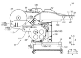
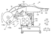
- FIG. 1 is a plan view illustrating a configuration of a component mounting apparatus provided with a component supply device according to an embodiment of the present invention. It is a side view showing the parts supply device by one embodiment of the present invention.
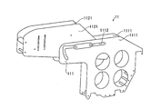
- FIG. 4 is a perspective view illustrating a reel disposition portion of the component supply device according to the embodiment of the present invention.
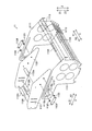
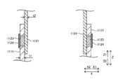
- FIG. 3 is an exploded perspective view of a reel disposition portion of the component supply device according to the embodiment of the present invention. It is a figure for explaining connection of the 1st reel arrangement part and the 2nd reel arrangement part of the reel arrangement part of the component supply device by one embodiment of the present invention. It is a figure for explaining width of a reel arrangement part of a parts supply device by one embodiment of the present invention.
- FIG. 4 is a diagram illustrating a storage position of a reel arrangement unit of the component supply device according to the embodiment of the present invention. It is a figure showing the pulling out position of the reel arrangement part of the parts supply device by one embodiment of the present invention.
- FIG. 5 is a diagram illustrating a rotation position of a reel arrangement portion of the component supply device according to the embodiment of the present invention. It is a figure for explaining removal of a reel of a parts supply device by one embodiment of the present invention.
- the component mounting apparatus 100 is a component mounting apparatus that transports the board S in the X direction by the pair of conveyors 2 and mounts the component 31 on the board S at the mounting operation position M.
- the component mounting apparatus 100 includes a base 1, a pair of conveyors 2, a component supply unit 3, a head unit 4, a support unit 5, a pair of rail units 6, a component recognition imaging unit 7, and a control unit 8. And
- the pair of conveyors 2 are installed on the base 1 and are configured to transport the substrate S in the X direction. Further, the pair of conveyors 2 is provided with a holding mechanism for holding the board S being transported in a stopped state at the mounting operation position M. Further, the pair of conveyors 2 is configured so that the interval in the Y direction can be adjusted according to the dimensions of the substrate S.
- the component supply unit 3 is arranged outside the pair of conveyors 2 (Y1 side and Y2 side). Further, the component supply unit 3 is provided with a component supply device 10. Each of the component supply devices 10 of the component supply unit 3 is configured to supply the component 31 to a mounting head 42 described later.
- the component supply device 10 holds a reel 34 on which a component supply tape 33 holding a plurality of components 31 at predetermined intervals is wound.
- the component supply device 10 includes a reel placement unit 11, a tape feeder 12, and a cart 13.
- the reel placement unit 11 can support a plurality of reels 34 around which a component supply tape 33 holding the components 31 to be mounted on the substrate S is wound.
- the tape feeder 12 is configured to send out the component supply tape 33 of the reel 34 placed on the reel placement unit 11 toward the component supply position 32.
- the tape feeder 12 of the component supply device 10 is configured to supply the component 31 from the tip of the component supply device 10 in the Y direction.
- the components 31 include electronic components such as ICs, transistors, capacitors, resistors, and connectors.
- a plurality of reel arrangement units 11 and a plurality of tape feeders 12 are arranged on the cart 13.
- a detailed description of the component supply device 10 will be described later.
- the tape feeder 12 is an example of the “feeder unit” in the claims.
- the cart 13 is an example of the “feeder arrangement section” in the claims.
- the head unit 4 is disposed above the pair of conveyors 2 and the component supply unit 3, and includes a plurality (five) of mounting heads 42 each having a nozzle 41 attached to a lower end thereof; And a recognition camera 43.
- the mounting head 42 is configured to mount the component 31 supplied from the component supply device 10 on the substrate S. Specifically, the mounting head 42 is configured to suck the component 31 supplied by the component supply unit 3 and mount the sucked component 31 on the board S disposed at the mounting operation position M. I have. Further, the mounting head 42 is configured to be able to move up and down (movable in the Z direction). Further, the mounting head 42 sucks and holds the component 31 supplied from the component supply device 10 by the negative pressure generated at the distal end portion of the nozzle 41 by a negative pressure generator (not shown). The component 31 is configured to be mounted (mounted) at the mounting position.
- the board recognition camera 43 is configured to image the fiducial mark F of the board S in order to recognize the position and orientation of the board S. By capturing and recognizing the position of the fiducial mark F, the mounting position of the component 31 on the substrate S can be accurately obtained.
- the support 5 includes a motor 51.
- the support unit 5 is configured to move the head unit 4 in the X direction along the support unit 5 by driving the motor 51. Both ends of the support portion 5 are supported by a pair of rail portions 6.
- the pair of rails 6 are fixed on the base 1.
- the rail section 6 on the X1 side includes a motor 61.
- the rail section 6 is configured to move the support section 5 in the Y direction orthogonal to the X direction along the pair of rail sections 6 by driving the motor 61. Since the head unit 4 is movable in the X direction along the support part 5 and the support part 5 is movable in the Y direction along the rail part 6, the head unit 4 is moved in the horizontal direction (XY direction). Can be moved.
- the component recognition imaging unit 7 is fixed on the upper surface of the base 1.
- the component recognition imaging unit 7 is arranged outside the pair of conveyors 2 (Y1 side and Y2 side).
- the component recognition imaging unit 7 images the component 31 sucked by the nozzle 41 of the mounting head 42 from below (Z2 side) in order to recognize the suction state (suction posture) of the component 31 prior to mounting the component 31. It is configured to Thus, the suction state of the component 31 sucked by the nozzle 41 of the mounting head 42 can be acquired by the control unit 8.
- the control unit 8 includes a CPU and a memory, and performs a component mounting apparatus 100 such as a transport operation of the substrate S by the pair of conveyors 2, a mounting operation by the head unit 4, and an imaging operation by the component recognition imaging unit 7 and the substrate recognition camera 43. Is configured to control the entire operation.
- the control unit 8 is configured to be able to communicate with a control unit (not shown) of the tape feeder 12.
- the control unit 8 is configured to control the mounting operation in cooperation with each control unit of the plurality of tape feeders 12.
- the component supply device 10 includes a reel placement unit 11, a tape feeder 12, and a cart 13.
- the reel placement unit 11 includes a first reel placement unit 111 and a second reel placement unit 112.
- the reel arrangement unit 11 is configured so that a plurality of reels 34 are arranged.
- the first reel arranging unit 111 of the reel arranging unit 11 is configured such that the reel 34 that first supplies the component supply tape 33 to the tape feeder 12 is arranged.
- the second reel arranging unit 112 of the reel arranging unit 11 is configured such that the reel 34 that supplies the component supply tape 33 to the tape feeder 12 is arranged next to the reel 34 that is arranged in the first reel arranging unit 111. Have been.
- the reel 34 arranged in the reel arrangement section 11 is, for example, a large-diameter reel having a relatively large diameter.
- the diameter of the reel 34 is 13 inches or more.
- the diameter of the reel 34 is, for example, 13 inches, 15 inches or 17 inches.
- the width of the component supply tape 33 wound around the reel 34 is, for example, 4 mm, 8 mm, 12 mm, or 16 mm. Also, the width of the component supply tape 33 may be a wider tape such as 72 mm or 104 mm.
- the tape feeder 12 is a feeder that can automatically load the component supply tape 33. That is, when the component supply tape 33 of the reel 34 disposed on the first reel placement unit 111 ends, the tape feeder 12 supplies the component supply tape 33 from the reel 34 disposed on the second reel placement unit 112. In this way, the components are automatically switched, and the supply of the parts 31 is continued.
- the tape feeder 12 includes an insertion-side sprocket 121, an intermediate sprocket 122, and a supply sprocket 123.
- the leading end of the component supply tape 33 wound around the reel 34 arranged on the second reel arrangement portion 112 is inserted from the insertion opening of the tape feeder 12, and the feed hole is fitted to the teeth of the insertion side sprocket 121. Waiting in a state. In this state, when it is detected that there is no component 31 to be supplied by the component supply tape 33 being unreeled from the reel 34 of the first reel placement unit 111, the insertion side sprocket 121 starts rotating and the subsequent component supply tape 33 is sent downstream to start automatic loading.
- the insertion side sprocket 121 can be a tape loading device that automatically conveys the inserted component supply tape 33 to the component supply position 32.
- the component supply tape 33 inserted from the insertion opening of the tape feeder 12 is placed on the support member from below and is fitted from below onto the teeth of the insertion side sprocket 121 in a supported state.
- An intermediate sprocket 122 and a supply sprocket 123 are arranged in the downstream direction.
- the component supply tape 33 is fitted to these sprockets (the intermediate sprocket 122 and the supply sprocket 123), and is sent from the upstream to the downstream by rotation of these sprockets.
- the drive source of the insertion side sprocket 121 may stop rotating, but rotates in synchronization with the supply sprocket 123. May be.
- a one-way clutch that allows only the rotation of the insertion side sprocket 121 in the tape feed direction may be provided.
- the component supply position 32 is preferably provided near the supply sprocket 123. Note that the intermediate sprocket 122 may not be provided.
- the exposing mechanism for exposing the upper part of the storage section from the cover tape of the component supply tape 33 is arranged at any position between the insertion side sprocket 121 and the supply sprocket 123.
- the supply sprocket 123 After the first component 31 reaches the component supply position 32 by the automatic loading of the component supply tape 33, the supply sprocket 123 intermittently sends the component supply tape 33 to supply the component 31. Also, every time the stop is performed intermittently, the component 31 is taken out at the component supply position 32 by the mounting head 42.
- the supply sprocket 123 may be a component supply and transport device that transports the component supply tape 33 for supplying the component 31.
- the reel 34 of the second reel placement unit 112 is moved to the first reel placement unit 111 at that time, and a new subsequent The reel 34 of the component supply tape 33 is arranged in the second reel arranging section 112, and a preset for inserting the subsequent component supply tape 33 from the insertion opening of the tape feeder 12 can be performed.
- the inserted component supply tape 33 waits in a state where it can be moved downstream by driving the insertion side sprocket 121. In this state, the insertion side sprocket 121 stops rotating.
- the preceding component supply tape 33 Before the subsequent component supply tape 33 is inserted into a position where it is fitted to the insertion-side sprocket 121, the preceding component supply tape 33 is separated from the insertion-side sprocket 121 by being unsupported by the support member (not shown). It is in a state. The preceding component supply tape 33 is intermittently fed by the drive of the supply sprocket 123 even if it comes off the insertion side sprocket 121, and the component 31 is supplied.
- the component supply tape 33 of the reel 34 arranged on the first reel arrangement unit 111 is automatically switched so that the component supply tape 33 is supplied from the reel 34 arranged on the second reel arrangement unit 112.
- an empty reel 34 is taken out from the first reel placement unit 111 by the operator.
- the reel 34 supplying the component 31 in the second reel placement unit 112 is moved from the second reel placement unit 112 to the first reel placement unit 111.
- the subsequent reel 34 is set in the second reel placement unit 112.
- the above-described reel exchange operation is repeated, so that the supply of the component 31 is continuously performed without stopping the supply of the component 31. Is possible.
- the above-described reel exchange operation can be performed at a timing convenient for the operator until the component 31 of the reel 34 arranged in the second reel arrangement unit 112 is cut off. It is possible to suppress an increase in the labor of a user for replacing the reels.
- a plurality of reel placement units 11 and a plurality of tape feeders 12 can be placed on the cart 13.
- the cart 13 includes a reel holding unit 131 that holds the reel 34, a support unit 132 provided on the reel holding unit 131, a tape box 133, and an arrangement unit 134.
- the support part 132 includes support parts 132a, 132b, and 132c, as shown in FIG.
- the support part 132 is formed so as to extend in the direction (X direction) in which the plurality of reels 34 are arranged.
- the support section 132 is configured to rotatably support the reel 34.
- the support part 132 includes a rotatable roller. That is, the reel 34 is configured so that the outer peripheral portion is supported by the support portion 132.
- the rotatable roller (support portion 132) is configured to abut on the outer periphery of the reel.
- the support part 132a is arranged below in the Y2 direction.
- the support 132b is arranged in the Y1 direction with respect to the support 132a.
- the support 132c is disposed above the support 132b in the Y1 direction.
- the cart 13 is provided with casters, and is configured to be movable with respect to the component mounting apparatus 100 while holding a plurality of tape feeders 12.
- the support 132 is an example of the “second support” in the claims.
- the tape feeder 12 is removably arranged in the arrangement section 134. That is, each of the plurality of tape feeders 12 can be attached to and detached from the cart 13. Thus, the tape feeder 12 corresponding to the reel 34 of the component 31 to be supplied can be arranged on the carriage 13.
- the reel placement unit 11 is configured such that the first reel placement unit 111 is supported by the support 132 of the cart 13.
- the reel placement unit 11 is configured such that the second reel placement unit 112 is movably supported by the first reel placement unit 111. That is, the reel placement unit 11 is hooked and installed on the support unit 132 of the cart 13.
- the first reel placement unit 111 is provided on a reel holding unit 131 provided on the carriage 13 on which the tape feeder 12 is placed and holding the reel 34. Further, the outer periphery of the reel 34 arranged on the first reel arrangement section 111 is supported by a support section 132 provided on a reel holding section 131 of the carriage 13.
- the reel placement unit 11 is detachable from the carriage 13, and the reel 34 can be supported by the support unit 132 and placed even without the reel placement unit 11.
- the tape feeder 12 is detachable from the carriage 13. Accordingly, the tape feeder 12 is arranged such that one of the reels 34 is put on standby by using two reels 34 as shown in FIG. Can be arranged on the carriage 13. Further, a tape feeder for supplying the components 31 stored in the component supply tape 33 using only one reel 34 without using the standby reel 34 can be arranged on the carriage 13. In this case, the reel 34 can be mounted on the carriage 13 by removing the reel placement unit 11.
- the tape feeder 12 using only one reel 34 can be used by arranging it on the trolley 13 even when the reel arranging unit 11 is attached to the trolley 13. Further, as shown in FIG. 1, a plurality of tape feeders can be arranged in the cart 13 in the X direction. Therefore, the tape feeder 12 using two reels 34 shown in FIG. 2 and the tape feeder using only one reel 34 shown in FIG. In this case, it is possible to cope with this by placing the reel placement unit 11 only at the place where the tape feeder 12 shown in FIG. 2 is placed.
- the tape box 133 is arranged below the reel arrangement part 11.
- the tape box 133 is configured to be able to be pulled out in the front direction (the direction moving away from the component mounting apparatus 100).
- the tape box 133 is configured to house the component supply tape 33 to which the components 31 have been supplied. That is, the tape box 133 can be pulled out without interfering with the reel placement unit 11, and in the pulled-out state, the component supply tape 33 inside can be taken out and disposed.
- the reel arranging unit 11 is configured to be detachable from a reel holding unit 131 provided on the carriage 13 on which the tape feeder 12 is arranged and holding the reel 34. That is, the reel placement unit 11 can be removed from the carriage 13 according to the size of the reel 34 and the frequency of use. Further, the first reel placement unit 111 is configured such that when the component supply tape 33 is supplied from the reel 34 to the tape feeder 12, the position with respect to the tape feeder 12 cannot be changed. That is, the first reel placement unit 111 is configured not to move when the component 31 is being supplied to the component mounting apparatus 100.
- the component supply tape 33 includes a carrier tape and a cover tape.
- the carrier tape is provided with a storage portion in which the component 31 is stored and an engagement hole that engages with a sprocket of the tape feeder 12.
- the storage section has a space larger than the size of the component 31.
- the upper part of the storage part is covered with a cover tape.
- the cover tape is cut open by the exposure mechanism, and the upper part of the storage unit is exposed.
- the exposing mechanism is not limited to the mode in which the cover tape is incised, but may be the mode in which only one side of the cover tape storage section is peeled and exposed.
- the first reel arranging part 111 of the reel arranging part 11 includes a pair of first plate-like members 1111, a guide part 1112, and a connecting part 1113.
- the guide part 1112 has a horizontal guide part 1112a, a positioning part 1112b, and a rotation guide part 1112c.
- the second reel arranging portion 112 of the reel arranging portion 11 includes a pair of second plate-like members 1121, support portions 1122 (1122a, 1122b, and 1122c), guided members 1123, a connecting member 1124, and a connecting portion 1125.
- the support 1122 is an example of the “first support” in the claims.
- the support portion 1122 and the connecting portion 1125 have an integral shape that connects the pair of second plate-like members 1121 in order to keep the distance between the pair of second plate-like members 1121 constant.
- the component supply tape 33 is fed from the reel 34 placed on the support portion 1122 and inserted into the tape feeder 12. Therefore, even if the reel 34 is moved to the left side in FIG. 2 or the like and is moved to the first reel placement unit 111 below the support 1122, the component supply tape 33 remains on the support 1122. Can not.
- the pair of first plate members 1111 of the first reel placement unit 111 are disposed so as to face each other in the rotation axis direction (X direction) of the reel 34.
- the pair of second plate-like members 1121 of the second reel disposing portion 112 are disposed so as to face each other in the rotation axis direction of the reel 34.
- the pair of second plate members 1121 is arranged inside the pair of first plate members 1111.
- the pair of first plate-like members 1111 are connected by a plurality of connecting portions 1113 at a predetermined interval.
- the pair of second plate-like members 1121 are connected at predetermined intervals by supporting portions 1122a, 1122b, 1122c and a connecting portion 1125.
- the second plate-like member 1121 is connected to the connecting member 1124 and the second plate-like member in a state where the two guided members 1123 are inserted into the guide portions 1112 of the first plate-like member 1111.
- the member 1121 is connected.
- the support portion 1122 is configured to rotatably support the reel 34.
- the support 1122 includes a rotatable roller.
- the pair of second plate-like members 1121 is configured to hold the supporting portion 1122 so as to be sandwiched therebetween and to be movable with respect to the pair of first plate-like members 1111 along the direction in which the first plate-like member 1111 extends. ing.
- the guide portion 1112 of the first plate member 1111 guides the movement of the pair of second plate members 1121 relative to the pair of first plate members 1111.
- guide portion 1112 includes a long hole provided in first plate-shaped member 1111. That is, the second plate-like member 1121 is guided along the elongated hole and is movable with respect to the first plate-like member 1111.
- the second reel placement unit 112 is configured to be horizontally and pivotally movable with respect to the first reel placement unit 111 by at least two guided members 1123 being guided by the guide unit 1112. ing.
- the horizontal guide portion 1112a of the guide portion 1112 guides the movement of the second plate member 1121 in the horizontal direction (Y direction). In this case, since both of the two guided members 1123 are located inside the horizontal guide portion 1112a, the horizontal posture of the second plate-like member 1121 is maintained.
- the positioning part 1112b of the guide part 1112 is configured to position the second plate-like member 1121 at a position during normal operation. Specifically, the positioning part 1112b is provided in the middle of the horizontal guide part 1112a, and is formed so as to be depressed downward. Thereby, the second plate-like member 1121 is positioned by fitting the guided member 1123 on the Y2 direction side into the positioning part 1112b. When releasing the positioning of the second plate-like member 1121, the guided member 1123 is moved out of the positioning part 1112b by lifting the second plate-like member 1121 upward. Thereby, the second plate-like member 1121 can be moved along the horizontal guide portion 1112a.
- the rotation guide portion 1112c of the guide portion 1112 guides the vertical rotation of the second plate-like member 1121.
- the guided member 1123 on the Y2 direction side is located in the rotation guide portion 1112c, and the guided member 1123 on the Y1 direction side is arranged in the horizontal guide portion 1112a on the Y1 direction side of the positioning portion 1112b.
- the second plate-like member 1121 is formed so as to have a smaller thickness than the first plate-like member 1111.
- the first plate-like member 1111 has a thickness of t1.
- the first plate-like member 1111 is formed of a metal material such as stainless steel and has a thickness of about 1.2 mm.
- the second plate-like member 1121 has a thickness of t2 (where t2 ⁇ t1).
- the second plate-like member 1121 is formed of a metal material such as stainless steel and has a thickness of about 0.8 mm. That is, the second plate-like member 1121 is formed to be more flexible than the first plate-like member 1111. Further, the first plate-like member 1111 is formed so as to have higher mechanical strength than the second plate-like member 1121.
- the first plate-like member 1111 and the second plate-like member 1121 are formed by sheet metal working.
- the pair of second plate-like members 1121 has an end (Y2 direction) farther from the tape feeder 12 than an interval between ends (Y1 direction end) on the tape feeder 12 side. (The end on the side) is configured to be larger. Specifically, the width in the X direction of the support portion 1122a disposed on the Y1 direction side is d1, and the width in the X direction of the support portion 1122c disposed on the Y2 direction side is d2 (where d2> d1). is there. Thereby, the interval between the pair of second plate-like members 1121 on the Y2 direction side is increased.
- the second plate-shaped members on both sides (X1 direction side and X2 direction side) of the reel placement unit 11 that one wants to access by exchanging the reel 34 or the like. It is possible to deflect 1121 to spread outward. In other words, it is possible to enlarge the region sandwiched therebetween by utilizing the elasticity of the second plate-like member 1121. Accordingly, a space for replacing the reel 34 can be ensured, so that the reel 34 can be arranged closely in the rotation axis direction (X direction).
- the reel arranging unit 11 is configured to move the first reel arranging unit 112 from the first reel arranging unit 112 in a state where the distance between the support unit 1122 (1122a) and the tape feeder 12 is equal to or larger than the diameter of the reel 34.
- a pair of second plate-like members 1121 and a pair of first plate-like members 1111 form a guide side wall that can continuously guide the reel 34 over the reel disposition portion 111.
- the second reel placement unit 112 can change the distance between the tape feeder 12 and the support unit 1122 (1122a) by changing the position of the support unit 1122 (1122a) with respect to the tape feeder 12. It is configured. Further, the support portion 1122 is configured to support the outer peripheral portion of the reel 34.
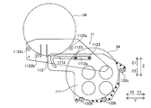
- the second reel disposition unit 112 determines the distance between the support unit 1122 (1122a) and the tape feeder 12 (that is, the distance between the support unit 1122a and the constituent parts of the tape feeder 12 and the carriage 13). Is shortest) is movable to a first position P1 where the reel 34 has a diameter d0 or more. As shown in FIG. 14, when the second reel placement unit 112 is located at the first position P1, the distance between the support unit 1122a and the tape feeder 12 is d4 (where d4 ⁇ d0).
- the second reel disposing portion 112 is configured to be movable with respect to the tape feeder 12 to a second position P2 where the distance between the support portion 1122 (1122a) and the tape feeder 12 is smaller than the diameter d0 of the reel 34. . As shown in FIG. 12, when the second reel placement unit 112 is located at the second position P2, the distance between the support unit 1122a and the tape feeder 12 is d3 (where d3 ⁇ d0).
- the reels 34 arranged on the second reel arrangement section 112 are in a state where the component supply tape 33 is being supplied to the tape feeder 12 and the second reel arrangement section 112 is in the first reel arrangement state.
- it is configured to be able to pass between the support part 1122 (1122 a) and the tape feeder 12 and move to the first reel arrangement part 111.
- the component supply tape 33 is detached downward from the insertion side sprocket 121, and the component 31 is supplied intermittently by only the intermediate sprocket 122 and the supply sprocket 123.
- the second reel placement section 112 is movable with respect to the first reel placement section 111 along a plane (YZ plane) perpendicular to the rotation axis direction of the reel 34. It is configured. That is, even when a plurality of reels 34 are arranged side by side in the rotation axis direction (X direction) of the reels 34, the second reel placement unit 112 can be moved with respect to the first reel placement unit 111 without interfering with each other. It is.
- the reel 34 arranged on the first reel arrangement part 111 passes below the support part 1122 (1122a) of the second reel arrangement part 112 and is taken out from the first reel arrangement part 111. It is configured to be possible. That is, even when a plurality of reels 34 are arranged side by side in the rotation axis direction (X direction) of the reels 34, the reels 34 can be taken out from the first reel arrangement unit 111 without interfering with the adjacent reel arrangement units 11. It is. In other words, the reel 34 can be replaced by moving the reel 34 in the Y direction and the Z direction without moving the reel 34 in the width direction (X direction) for one reel placement unit 11. It is.
- the second reel disposing portion 112 pivotally moves downward (Z2 direction) with respect to the first reel disposing portion 111, so that the tape feeder 12 and the support portion 1122 (1122a) are rotated. Is configured to be large. Specifically, as shown in FIGS. 12 to 14, the second reel placement unit 112 moves in a direction away from the tape feeder 12 along the horizontal direction with respect to the first reel placement unit 111, and The space between the tape feeder 12 and the support portion 1122 (1122a) is increased by rotating downward with respect to the reel placement portion 111.
- the first reel placement unit 111 and the second reel placement unit 112 are disposed at positions offset from the component supply position 32 of the tape feeder 12 in plan view (when viewed in the Z direction). That is, the reel 34 is not arranged below the tape feeder 12 on the Y1 direction side. Thus, a space above the tape box 133 can be secured.
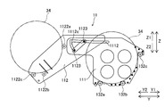
- the reel placement unit 11 is located at a position where one of the guided members 1123 (on the Y2 direction side) is engaged with the positioning unit 1112 b of the guide unit 1112. , A second reel arranging section 112 is arranged. In this state, the distance between the support portion 1122a and the support portion 132a is equal to or larger than the diameter d0 of the reel 34.
- the basic form is such that the preceding reel 34 is placed in the first reel placement unit 111 and the subsequent preset reel 34 is placed in the second reel placement unit 112. .
- the other guided member 1123 (on the Y1 direction side) is positioned on the Y1 direction side of the horizontal guide unit 1112 a of the guide unit 1112.
- the second reel placement unit 112 is placed at a position where it comes into contact with the end.
- the distance between the support portion 1122a and the support portion 132a is smaller than the diameter d0 of the reel 34.
- the guided member 1123 is moved in the Y2 direction, the distance between the support portion 1122a and the support portion 132a can be made larger than the diameter d0 of the reel 34.
- the second reel disposition unit In the storage position of the reel disposition unit 11, the second reel disposition unit is used when it is necessary to temporarily increase the space in front (Y2 direction side), for example, when a workbench or the like is passed through a passage between the equipment lines.
- 112 is the location where it is stored. Even at the position of the guided member 1123 shown in FIG. 9, the feeding operation of the component supply tape 33 of the reel 34 arranged on the second reel arrangement portion 112 by the tape feeder 12 can be performed without any trouble. Further, it is also possible to prevent the traffic of the worker from being hindered. Further, when not in use, the second reel placement section 112 can be stored in the storage position to be compact.
- one of the guided members 1123 (on the Y2 direction side) is the end of the horizontal guide unit 1112 a of the guide unit 1112 on the Y2 direction side.
- the second reel arranging unit 112 is arranged at a position where the second reel arranging unit 112 contacts the unit.
- the component 31 (the component supply tape 33) of the reel 34 of the first reel placement unit 111 runs out
- the component 31 (the component supply tape 33) is transferred from the reel 34 preset in the second reel placement unit 112. Is supplied.
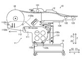
- the empty reel 34 is taken out from the first reel placement unit 111 in the direction of the arrow by passing below the support unit 1122a.
- the second reel placement section 112 is pulled out in a direction (Y2 direction) away from the tape feeder 12. Then, as shown in FIG. 14, the second reel placement section 112 is rotated downward. Further, the preset component supply tape 33 is lowered to the preceding tape position of the tape feeder 12 (tape dropping is performed). In this state, the component supply tape 33 of the second reel placement unit 112 is loosened to some extent due to the movement of the second reel placement unit 112, so that the reel 34 can be easily moved. If the slack is small, the worker may pull out the component supply tape 33 from the reel 34.
- the reel 34 is moved from the second reel placement unit 112 to the first reel placement unit 111. At this time, the supply of the component 31 (the component supply tape 33) to the tape feeder 12 is being performed continuously. The reel 34 is moved between the support portion 1122a and the tape feeder 12. Thereafter, as shown in FIG. 2, the second reel placement unit 112 is moved to a position during normal operation. Then, a preset reel 34 subsequent to the second reel placement unit 112 is placed.
- the reel placement unit 11 (the second reel placement unit 112) may be moved with respect to the tape feeder 12 by an interval at which the reel 34 can be moved with the tape feeder 12.
- the reel placement unit 11 can support a plurality of reels 34 around which the component supply tape 33 is wound. Can be prevented from increasing the area to be secured. Further, by changing the position of the support portion 1122 with respect to the tape feeder 12, the distance between the tape feeder 12 and the support portion 1122 (1122a) can be increased. The reel 34 can be easily moved from the 112. When the reel 34 is not replaced, the second reel placement section 112 can be brought closer to the tape feeder 12 by reducing the distance between the tape feeder 12 and the support section 1122. The arrangement area can be reduced.
- the second reel disposition unit 112 is divided into the first position P1 where the distance between the support unit 1122 (1122a) and the tape feeder 12 is equal to or larger than the diameter of the reel 34, and the support unit 1122. (1122a) and the tape feeder 12 can be moved relative to the tape feeder 12 to a second position P2 where the distance is smaller than the diameter of the reel 34.
- the second reel placement section 112 can be close to the tape feeder 12, so that the placement area of the reel placement section 11 can be effectively reduced. it can.
- the reels 34 arranged on the second reel arrangement unit 112 are in a state where the component supply tape 33 is supplied to the tape feeder 12 and the second reel arrangement unit 112 Are arranged at the first position P1 so as to pass between the support portion 1122 (1122a) and the tape feeder 12 and move to the first reel placement portion 111.
- This makes it possible to easily move the reels 34 arranged on the second reel arrangement section 112 to the first reel arrangement section 111 while maintaining the state in which the component supply tape 33 is supplied to the tape feeder 12.
- the reels 34 arranged on the reel arrangement section 11 can be replaced more easily.
- the second reel placement unit 112 is configured to be movable with respect to the first reel placement unit 111 along a plane perpendicular to the rotation axis direction of the reel 34.
- the reel 34 can be replaced by moving the reel along a plane perpendicular to the rotation axis direction of the reel 34, so that the reel placement unit 11 and the rotation axis are moved in the rotation axis direction of the reel 34. You don't have to.
- the reels 34 can be easily moved.
- the tape feeder 12 and the support portion 1122 are rotated by moving the second reel placement portion 112 downward (Z2 direction) with respect to the first reel placement portion 111. (1122a).
- the horizontal movement range can be reduced, so that the space reserved for the component supply device 10 is increased. Can be suppressed.
- the second reel placement unit 112 is moved in the direction away from the tape feeder 12 along the horizontal direction with respect to the first reel placement unit 111, and the first reel placement unit 112 is moved.
- the distance between the tape feeder 12 and the support portion 1122 (1122a) is increased.
- the distance between the tape feeder 12 and the support portion 1122 (1122a) can be effectively increased by moving the second reel placement portion 112 in combination with the horizontal and downward rotation. it can.
- the component supply tape 33 can be pulled out from the reel. Accordingly, when the reel 34 is moved, the component supply tape 33 can be slackened, so that the reel 34 can be more easily moved.
- the reel 34 arranged on the first reel arrangement part 111 passes below the support part 1122 (1122a) of the second reel arrangement part 112, and It is configured to be able to be taken out from the device 111.
- the reel 34 arranged on the first reel arranging unit 111 and previously supplied with the component supply tape 33 can be taken out from below the second reel arranging unit 112.
- the reel 34 of the first reel placement unit 111 can be taken out without interfering with the reel 34.
- the first reel placement unit 111 is set so that the position with respect to the tape feeder 12 cannot be changed when the component supply tape 33 is supplied from the reel 34 to the tape feeder 12. Constitute. This eliminates the need to provide a mechanism for moving the first reel placement unit 111 when supplying the component supply tape 33, so that the configuration of the reel placement unit 11 can be prevented from becoming complicated.
- the outer periphery of the reel 34 arranged on the first reel arrangement part 111 is supported by the support part 132 provided on the reel holding part 131 of the cart 13. Have been.
- the outer peripheral portion of the reel 34 of the first reel disposing portion 111 can be supported by using the support portion 132 provided on the reel holding portion 131 of the carriage 13. There is no need to separately provide a member for supporting the outer peripheral portion of the.
- the first reel placement section 111 is supported by the support section 132 of the carriage 13, and the second reel placement section 112 is moved to the first reel placement section 111. It is configured to be movably supported by Thus, the first reel placement section 111 and the second reel placement section 112 can be supported by using the support section 132 provided on the reel holding section 131 of the cart 13, so that the first reel placement section 111 There is no need to separately provide a supporting member.
- the first reel disposing portion 111 includes the pair of first plate-like members 1111 disposed so as to oppose each other in the rotation axis direction (X direction) of the reel 34.
- the two-reel arrangement part 112 includes a pair of second plate-like members 1121 arranged to face each other in the rotation axis direction of the reel 34.
- the pair of second plate-like members 1121 is configured to hold the supporting portion 1122 so as to be sandwiched therebetween and to be movable with respect to the pair of first plate-like members 1111 along the direction in which the first plate-like member 1111 extends. ing.
- the first reel placement section 111 and the second reel placement section 112 are separated by the pair of first plate-like members 1111 and second plate-like members 1121 while separating adjacent reels 34 in the rotation axis direction (X direction).
- the reel 34 can be held.
- the second plate-like member 1121 can be slid along the first plate-like member 1111, the second reel placement section 112 can be easily moved in the direction in which the first plate-like member 1111 extends. .
- the second reel placement unit 112 is located on the reel placement unit 11 at a position where the distance between the support unit 1122 (1122a) and the tape feeder 12 is equal to or greater than the diameter of the reel 34.
- a pair of second plate-like members 1121 and a pair of first plate-like members are used to form a guide side wall capable of continuously guiding the reel 34 from the second reel placement part 112 to the first reel placement part 111. 1111. Accordingly, when the reel 34 is moved from the second reel placement unit 112 to the first reel placement unit 111, the reel 34 is sandwiched between the pair of second plate members 1121 and the pair of first plate members 1111. Can be maintained, so that the reel 34 can be easily moved from the second reel placement unit 112 to the first reel placement unit 111.
- At least one of the pair of first plate members 1111 has a guide portion that guides the movement of the pair of second plate members 1121 relative to the pair of first plate members 1111.
- 1112 is provided.
- the pair of second plate-like members 1121 is configured to be movable along the guide portion 1112. Accordingly, the second plate-like member 1121 can be easily moved along the guide portion 1112 of the first plate-like member 1111.
- the guide portion 1112 includes the elongated hole provided in the first plate-like member 1111. Accordingly, the movable area of the second plate-like member 1121 can be defined along the long hole, so that the second plate-like member 1121 is prevented from being moved to a position outside the predetermined range. it can.
- the second reel placement unit 112 is moved relative to the first reel placement unit 111 by guiding at least two guided members 1123 with respect to the guide unit 1112. It is configured to be able to move horizontally and rotate. Accordingly, the second reel placement portion 112 can be stably supported by the two or more guided members 1123. When the second reel placement section 112 is rotated, the second reel placement section 112 is easily rotated by guiding one guided member 1123 with the other guided member 1123 as a fulcrum. be able to.
- the pair of second plate-like members 1121 is formed such that the distance between the ends on the far side from the tape feeder 12 is larger than the distance between the ends on the tape feeder 12 side. To be configured. This makes it easy to insert the reel 34 from the side far from the tape feeder 12, so that the reel 34 can be easily arranged in the second reel arrangement section 112.
- the pair of second plate members 1121 is arranged inside the pair of first plate members 1111. Accordingly, the movable second plate-like member 1121 can be disposed inside the first plate-like member 1111, so that the movement of the second plate-like member 1121 to another member adjacent in the rotation axis direction of the reel 34. Can be suppressed from being interfered.
- the second plate-like member 1121 is formed so as to have a smaller thickness than the first plate-like member 1111. Accordingly, it is possible to suppress an increase in the width of the second reel placement portion 112 in the rotation axis direction of the reel 34. In addition, since the second plate-like member 1121 can be easily bent and deformed, the distance between the pair of second plate-like members 1121 is increased by bending the second plate-like member 1121 so that the second reel placement portion 112 The reel 34 can be easily arranged.
- the reel placement unit 11 is configured to be detachable from the reel holding unit 131 provided on the carriage 13 on which the tape feeder 12 is placed and holding the reel 34.
- the component placement device 10 can be used by removing the reel placement unit 11, so that the placement area of the component supply device 10 is reduced by the removed reel placement unit 11. Can be smaller.
- the first reel placement unit 111 and the second reel placement unit 112 are offset with respect to the component supply position 32 of the tape feeder 12 in plan view (when viewed in the Z direction). Place it in the position you specified.
- the area below the component supply position 32 can be kept free, so that a space for accommodating the used component supply tape 33 and a space for other things such as the space for the component mounting apparatus 100 are secured. be able to.
- the reel arrangement section is mounted on a cart (feeder arrangement section), but the present invention is not limited to this.
- the reel arrangement section may be directly attached to the feeder section.
- the reel arrangement section is configured to be detachable, but the present invention is not limited to this.
- the reel arrangement portion may be fixedly provided.
- the guide portion for guiding the second plate-shaped member is provided on both of the pair of first plate-shaped members, but the present invention is not limited to this.
- the guide portion may be provided on only one of the pair of first plate members.
- the first support portion may be moved relative to the second reel arrangement portion.
- the structure of the tape feeder is not only a mechanism for dropping the leading tape down and fitting the succeeding tape to the insertion side sprocket, but also for placing the leading tape on the insertion side sprocket and forming the tape.
- the feed hole engages the sprocket teeth from above and feeds it downstream by rotation of the sprocket, and the subsequent tape is placed on top of the preceding tape in a state where it is not fitted to the sprocket teeth and put on standby
- the leading tape continues to be fed by the downstream supply sprocket and the leading tape cannot be fitted to the insertion sprocket
- the trailing tape is fitted to the insertion sprocket to drive the insertion sprocket.
- a mechanism for performing automatic loading may be used.
- the reel arrangement unit similar to that shown in FIG. 3 can be used to move the reel for presetting the succeeding tape after the automatic loading of the preceding tape.
Landscapes
- Engineering & Computer Science (AREA)
- Manufacturing & Machinery (AREA)
- Microelectronics & Electronic Packaging (AREA)
- Operations Research (AREA)
- Supply And Installment Of Electrical Components (AREA)
Abstract
この部品供給装置(10)は、部品供給テープ(33)が巻き回されているリール(34)を複数支持することが可能なリール配置部(11)と、部品供給テープ(33)を部品供給位置(32)に向けて送り出すフィーダ部(12)とを備える。リール配置部(11)は、第1リール配置部(111)と、リール(34)の外周部を支持する第1支持部(1122)を有する第2リール配置部(112)と、を含む。第2リール配置部(112)は、フィーダ部(12)に対する第1支持部(1122)の位置を変更することによりフィーダ部(12)と第1支持部(1122)との間隔を変更可能に構成されている。
Description
この発明は、部品供給装置に関し、特に、部品供給テープが巻き回されているリールを複数支持することが可能なリール配置部を備えた部品供給装置に関する。
従来、部品供給テープが巻き回されているリールを複数支持することが可能なリール配置部を備えた部品供給装置が知られている。このような部品供給装置は、たとえば、国際公開第2016/002085号公報に開示されている。
上記国際公開第2016/002085号公報には、部品供給テープが巻き回されているリールを複数支持することが可能なリール保持部(リール配置部)と、リール保持部に保持された部品供給テープを部品供給位置に向けて送り出すフィーダ本体と、を備えるテープフィーダ(部品供給装置)が開示されている。このテープフィーダでは、リール保持部は、係合ピンをリールの回転軸孔に係合させて、リールを回転可能に保持するように構成されている。また、このテープフィーダでは、リール保持部に保持されたリールを交換する場合に、係合ピンの抜き差し作業やリールの移動作業時に、フィーダ本体および隣接するリールが干渉しないように、リール保持部がフィーダ本体に対して遠ざかる方向に移動可能に構成されている。
しかしながら、上記国際公開第2016/002085号公報のテープフィーダ(部品供給装置)では、リール保持部に保持されたリールを交換する場合に、係合ピンの抜き差し作業やリールの移動作業時に、フィーダ本体および隣接するリールが干渉しないように、リール保持部をフィーダ本体に対して遠ざける方向に移動させる。このため、リールの回転軸孔に係合ピンを抜き差しする際には、隣接するリールに干渉しないようにするためには、リール保持部をフィーダ本体に対して大きく移動させる必要がある。つまり、リールの回転軸線方向にみて、交換するリールの回転軸を隣接するリールと重ならない位置まで大きく移動させて引き出す必要がある。このため、リール保持部を大きく移動させる分だけ、リール保持部の配置領域を大きく確保する必要があるという問題点がある。
この発明は、上記のような課題を解決するためになされたものであり、この発明の1つの目的は、部品供給テープが巻き回されているリールを複数支持することが可能なリール配置部のために確保する領域が大きくなるのを抑制することが可能な部品供給装置を提供することである。
上記目的を達成するために、この発明の一の局面による部品供給装置は、基板に実装する部品が保持された部品供給テープが巻き回されているリールを複数支持することが可能なリール配置部と、リール配置部に載置されたリールの部品供給テープを部品供給位置に向けて送り出すフィーダ部とを備え、リール配置部は、フィーダ部に部品供給テープを先に供給するリールが配置される第1リール配置部と、第1リール配置部に配置されたリールに続いてフィーダ部に部品供給テープを供給するリールの外周部を支持する第1支持部を有する第2リール配置部と、を含み、第2リール配置部は、フィーダ部に対する第1支持部の位置を変更することによりフィーダ部と第1支持部との間隔を変更可能に構成されている。
この発明の一の局面による部品供給装置では、上記のように構成することによって、第2リール配置部の第1支持部によりリールの外周部を支持することができるので、リールの回転軸を支持する必要がない。このため、リールを移動させる場合に、回転軸線方向に回転軸を抜き差しして移動させる必要がない。これにより、リールの回転軸線方向にみて、交換するリールの回転軸を隣接するリールと重ならない位置まで大きく移動させて引き出す必要がない。すなわち、フィーダ部との間でリールを移動させることが可能な間隔分だけリール配置部をフィーダ部に対して移動させればよい。その結果、第2リール配置部を大きく移動させるための領域を確保する必要がないので、部品供給テープが巻き回されているリールを複数支持することが可能なリール配置部のために確保する領域が大きくなるのを抑制することができる。また、フィーダ部に対する第1支持部の位置を変更することによりフィーダ部と第1支持部との間隔を大きくすることができるので、フィーダ部に干渉することなく第2リール配置部からリールを容易に移動させることができる。また、リールを交換しない場合には、フィーダ部と第1支持部との間隔を小さくするようにして、第2リール配置部をフィーダ部に近づけることができるので、リール配置部の配置領域を小さくすることができる。
上記一の局面による部品供給装置において、好ましくは、第2リール配置部は、第1支持部とフィーダ部との間隔がリールの直径以上となる第1位置と、第1支持部とフィーダ部との間隔がリールの直径未満となる第2位置と、にフィーダ部に対して移動可能に構成されている。このように構成すれば、第2リール配置部を第1位置とした状態において、第2リール配置部のリールをフィーダ部と第1支持部との間を通して移動させることができる。また、第2リール配置部を第2位置とした状態では、第2リール配置部をフィーダ部に近づけることができるので、リール配置部の配置領域を効果的に小さくすることができる。
この場合、好ましくは、第2リール配置部に配置されたリールは、フィーダ部に部品供給テープを供給している状態で、かつ、第2リール配置部が第1位置に配置されている状態で、第1支持部とフィーダ部との間を通過して、第1リール配置部に移動可能に構成されている。このように構成すれば、第2リール配置部に配置されたリールを、フィーダ部に部品供給テープを供給した状態を維持しながら、第1リール配置部に容易に移動させることができる。その結果、リール配置部に配置されたリールをより容易に交換することができる。
上記一の局面による部品供給装置において、好ましくは、第2リール配置部は、リールの回転軸線方向に垂直な面に沿って、第1リール配置部に対して移動可能に構成されている。このように構成すれば、リールの回転軸線方向に垂直な面に沿ってリールを移動させることにより、リールの交換を行うことができるので、リールの回転軸線方向にリール配置部や回転軸を移動させる必要がない。これにより、回転軸線方向にリールが隣接している場合でも、リールを容易に移動させることができる。
この場合、好ましくは、第2リール配置部は、第1リール配置部に対して下方向に回動移動することにより、フィーダ部と第1支持部との間隔が大きくなるように構成されている。このように構成すれば、第2リール配置部をフィーダ部と離す水平方向に移動させる場合と異なり、水平方向の移動範囲を小さくすることができるので、部品供給装置のために確保するスペースが大きくなるのを抑制することができる。
上記第2リール配置部が第1リール配置部に対して下方向に回動移動する構成において、好ましくは、第2リール配置部は、第1リール配置部に対して水平方向に沿ってフィーダ部に遠ざかる方向に移動して、第1リール配置部に対して下方向に回動移動することにより、フィーダ部と第1支持部との間隔が大きくなるように構成されている。このように構成すれば、第2リール配置部を水平方向と下方向への回動移動とを組み合わせて移動させることにより、フィーダ部と第1支持部との間隔を効果的に大きくすることができる。また、フィーダ部から第2リール配置部を遠ざけることにより、部品供給テープをリールから引き出すことができる。これにより、リールを移動させる際に、部品供給テープを弛ませることができるので、リールをより容易に移動させることができる。
上記一の局面による部品供給装置において、好ましくは、第1リール配置部に配置されたリールは、第2リール配置部の第1支持部の下方を通って、第1リール配置部から取り出すことが可能に構成されている。このように構成すれば、第1リール配置部に配置されて先行して部品供給テープを供給したリールを、第2リール配置部の下方から取り出すことができるので、第2リール配置部のリールに干渉することなく、第1リール配置部のリールを取り出すことができる。
上記一の局面による部品供給装置において、好ましくは、第1リール配置部は、リールからフィーダ部に部品供給テープが供給されている場合に、フィーダ部に対する位置が変えられないように構成されている。このように構成すれば、第1リール配置部を部品供給テープ供給時に移動させるための機構を設ける必要がないので、リール配置部の構成が複雑になるのを抑制することができる。
上記一の局面による部品供給装置において、好ましくは、第1リール配置部は、フィーダ部が配置されるフィーダ配置部に設けられリールが保持されるリール保持部に配置され、第1リール配置部に配置されたリールは、フィーダ配置部のリール保持部に設けられた第2支持部により外周部が支持されるように構成されている。このように構成すれば、フィーダ配置部のリール保持部に設けられた第2支持部を利用して、第1リール配置部のリールの外周部を支持することができるので、第1リール配置部にリールの外周部を支持する部材を別途設ける必要がない。
この場合、好ましくは、リール配置部は、第1リール配置部がフィーダ配置部の第2支持部に支持されるとともに、第2リール配置部が第1リール配置部により移動可能に支持されるように構成されている。このように構成すれば、フィーダ配置部のリール保持部に設けられた第2支持部を利用して、第1リール配置部および第2リール配置部を支持することができるので、第1リール配置部を支持するための部材を別途設ける必要がない。
上記一の局面による部品供給装置において、好ましくは、第1リール配置部は、リールの回転軸線方向に対向するように配置された一対の第1板状部材を含み、第2リール配置部は、リールの回転軸線方向に対向するように配置された一対の第2板状部材を含み、一対の第2板状部材は、第1支持部を挟み込むように保持するとともに、一対の第1板状部材に対して、第1板状部材が延びる方向に沿って移動可能に構成されている。このように構成すれば、一対の第1板状部材および第2板状部材により、回転軸線方向に隣接するリール同士を仕切りながら、第1リール配置部および第2リール配置部によりリールを保持することができる。また、第2板状部材を第1板状部材に沿ってスライド移動させることができるので、第2リール配置部を第1板状部材が延びる方向に容易に移動させることができる。
この場合、好ましくは、リール配置部は、第1支持部とフィーダ部との間隔がリールの直径以上となる位置に第2リール配置部が位置した状態で、第2リール配置部から第1リール配置部にかけて、連続してリールを案内することが可能なガイド側壁を、一対の第2板状部材および一対の第1板状部材により形成している。このように構成すれば、第2リール配置部から第1リール配置部にリールを移動する場合に、一対の第2板状部材および一対の第1板状部材により、リールを挟み込んだ状態を維持することができるので、リールを第2リール配置部から第1リール配置部により容易に移動させることができる。
上記第1リール配置部が一対の第1板状部材を含み、第2リール配置部が一対の第2板状部材を含む構成において、好ましくは、一対の第1板状部材の少なくとも一方には、一対の第1板状部材に対する一対の第2板状部材の移動をガイドするガイド部が設けられており、一対の第2板状部材は、ガイド部に沿って移動可能に構成されている。このように構成すれば、第2板状部材を第1板状部材のガイド部に沿って、容易に移動させることができる。
この場合、好ましくは、ガイド部は、第1板状部材に設けられた長穴を含む。このように構成すれば、第2板状部材の移動可能な領域を長穴に沿って規定することができるので、第2板状部材が所定の範囲外の位置に移動されるのを抑制することができる。
上記第1板状部材にガイド部が設けられている構成において、好ましくは、第2リール配置部は、ガイド部に対して少なくも2つの被ガイド部材が案内されることにより、第1リール配置部に対して水平移動および回動移動可能に構成されている。このように構成すれば、2つ以上の被ガイド部材により安定して第2リール配置部を支持することができる。また、第2リール配置部を回動移動させる場合に、一方の被ガイド部材を支点として他方の被ガイド部材をガイドすることにより、第2リール配置部を容易に回動移動させることができる。
上記第1リール配置部が一対の第1板状部材を含み、第2リール配置部が一対の第2板状部材を含む構成において、好ましくは、一対の第2板状部材は、フィーダ部側の端部の間隔よりもフィーダ部と遠い側の端部の間隔の方が大きくなるように構成されている。このように構成すれば、フィーダ部と遠い側からリールを入れやすくすることができるので、第2リール配置部にリールを容易に配置することができる。
上記第1リール配置部が一対の第1板状部材を含み、第2リール配置部が一対の第2板状部材を含む構成において、好ましくは、一対の第2板状部材は、一対の第1板状部材の内側に配置されている。このように構成すれば、可動する第2板状部材を第1板状部材の内側に配置することができるので、リールの回転軸線方向に隣接する他の部材に、第2板状部材の移動が干渉されるのを抑制することができる。
上記第1リール配置部が一対の第1板状部材を含み、第2リール配置部が一対の第2板状部材を含む構成において、好ましくは、第2板状部材は、第1板状部材よりも厚みが小さく形成されている。このように構成すれば、リールの回転軸線方向における第2リール配置部の幅が大きくなるのを抑制することができる。また、第2板状部材を撓み変形しやすくすることができるので、第2板状部材を撓ませて一対の第2板状部材の間隔を広げることにより、第2リール配置部にリールを容易に配置することができる。
上記一の局面による部品供給装置において、好ましくは、リール配置部は、フィーダ部が配置されるフィーダ配置部に設けられリールが保持されるリール保持部に対して着脱可能に構成されている。このように構成すれば、リール配置部を使用しない場合にはリール配置部を取り外して部品供給装置を使用することができるので、取り外したリール配置部の分だけ、部品供給装置の配置領域を小さくすることができる。
上記一の局面による部品供給装置において、好ましくは、第1リール配置部および第2リール配置部は、平面視において、フィーダ部の部品供給位置に対してオフセットした位置に配置されている。このように構成すれば、部品供給位置の下方の領域を空けておくことができるので、使用済みの部品供給テープを収容する空間や、部品実装装置の空間などの他のもののための空間を確保することができる。
本発明によれば、上記のように、部品供給テープが巻き回されているリールを複数支持することが可能なリール配置部のために確保する領域が大きくなるのを抑制することができる。
以下、本発明を具体化した実施形態を図面に基づいて説明する。
(部品実装装置の構成)
図1を参照して、本発明の実施形態による部品供給装置10が設けられた部品実装装置100の構成について説明する。
図1を参照して、本発明の実施形態による部品供給装置10が設けられた部品実装装置100の構成について説明する。
図1に示すように、部品実装装置100は、一対のコンベア2により基板SをX方向に搬送し、実装作業位置Mにおいて基板Sに部品31を実装する部品実装装置である。
部品実装装置100は、基台1と、一対のコンベア2と、部品供給部3と、ヘッドユニット4と、支持部5と、一対のレール部6と、部品認識撮像部7と、制御部8とを備えている。
一対のコンベア2は、基台1上に設置され、基板SをX方向に搬送するように構成されている。また、一対のコンベア2には、搬送中の基板Sを実装作業位置Mで停止させた状態で保持する保持機構が設けられている。また、一対のコンベア2は、基板Sの寸法に合わせてY方向の間隔を調整可能に構成されている。
部品供給部3は、一対のコンベア2の外側(Y1側およびY2側)に配置されている。また、部品供給部3には、部品供給装置10が設けられている。部品供給部3の部品供給装置10は、それぞれ、後述する実装ヘッド42に対して部品31を供給するように構成されている。
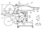
部品供給装置10は、図2に示すように、複数の部品31を所定の間隔を隔てて保持した部品供給テープ33が巻き付けられたリール34を保持している。部品供給装置10は、リール配置部11と、テープフィーダ12と、台車13とを含んでいる。リール配置部11は、基板Sに実装する部品31が保持された部品供給テープ33が巻き回されているリール34を複数支持することが可能である。テープフィーダ12は、リール配置部11に載置されたリール34の部品供給テープ33を部品供給位置32に向けて送り出すように構成されている。部品供給装置10のテープフィーダ12は、部品供給装置10のY方向の先端から部品31を供給するように構成されている。ここで、部品31は、IC、トランジスタ、コンデンサ、抵抗、コネクタなどの電子部品を含む。台車13には、複数のリール配置部11と、複数のテープフィーダ12とが配置されている。なお、部品供給装置10の詳細な説明については、後述する。なお、テープフィーダ12は、請求の範囲の「フィーダ部」の一例である。また、台車13は、請求の範囲の「フィーダ配置部」の一例である。
図1に示すように、ヘッドユニット4は、一対のコンベア2および部品供給部3の上方位置に配置されており、ノズル41が下端に取り付けられた複数(5つ)の実装ヘッド42と、基板認識カメラ43とを含んでいる。
実装ヘッド42は、部品供給装置10から供給される部品31を基板Sに実装するように構成されている。具体的には、実装ヘッド42は、部品供給部3により供給される部品31を吸着して、実装作業位置Mに配置された基板Sに対して吸着した部品31を装着するように構成されている。また、実装ヘッド42は、昇降可能(Z方向に移動可能)に構成されている。また、実装ヘッド42は、負圧発生機(図示せず)によりノズル41の先端部に発生された負圧によって、部品供給装置10から供給される部品31を吸着して保持し、基板Sにおける実装位置に部品31を装着(実装)するように構成されている。
基板認識カメラ43は、基板Sの位置および姿勢を認識するために、基板SのフィデューシャルマークFを撮像するように構成されている。そして、フィデューシャルマークFの位置を撮像して認識することにより、基板Sにおける部品31の実装位置を正確に取得することが可能である。
支持部5は、モータ51を含んでいる。支持部5は、モータ51を駆動させることにより、支持部5に沿ってヘッドユニット4をX方向に移動させるように構成されている。支持部5は、両端部が一対のレール部6により支持されている。
一対のレール部6は、基台1上に固定されている。X1側のレール部6は、モータ61を含んでいる。レール部6は、モータ61を駆動させることにより、支持部5を一対のレール部6に沿ってX方向と直交するY方向に移動させるように構成されている。ヘッドユニット4が支持部5に沿ってX方向に移動可能であるとともに、支持部5がレール部6に沿ってY方向に移動可能であることによって、ヘッドユニット4は水平方向(XY方向)に移動可能である。
部品認識撮像部7は、基台1の上面上に固定されている。部品認識撮像部7は、一対のコンベア2の外側(Y1側およびY2側)に配置されている。部品認識撮像部7は、部品31の実装に先立って部品31の吸着状態(吸着姿勢)を認識するために、実装ヘッド42のノズル41に吸着された部品31を下側(Z2側)から撮像するように構成されている。これにより、実装ヘッド42のノズル41に吸着された部品31の吸着状態を制御部8により取得することが可能である。
制御部8は、CPU、メモリを含んでおり、一対のコンベア2による基板Sの搬送動作、ヘッドユニット4による実装動作、部品認識撮像部7および基板認識カメラ43による撮像動作などの部品実装装置100の全体の動作を制御するように構成されている。また、制御部8は、テープフィーダ12の制御部(図示せず)と通信可能に構成されている。制御部8は、複数のテープフィーダ12の各々の制御部と連携して、実装動作を制御するように構成されている。
(部品供給装置の構成)
図2~図15を参照して、本発明の実施形態による部品供給装置10の構成について説明する。
図2~図15を参照して、本発明の実施形態による部品供給装置10の構成について説明する。
図2に示すように、部品供給装置10は、リール配置部11と、テープフィーダ12と、台車13とを備えている。リール配置部11は、第1リール配置部111と、第2リール配置部112とを含んでいる。リール配置部11には、複数のリール34が配置されるように構成されている。具体的には、リール配置部11の第1リール配置部111は、テープフィーダ12に部品供給テープ33を先に供給するリール34が配置されるように構成されている。また、リール配置部11の第2リール配置部112は、第1リール配置部111に配置されたリール34に続いてテープフィーダ12に部品供給テープ33を供給するリール34が配置されるように構成されている。リール配置部11に配置されるリール34は、たとえば、比較的直径が大きい大径リールである。リール34の直径は、13インチ以上である。リール34の直径は、たとえば、13インチ、15インチまたは17インチである。リール34に巻き回される部品供給テープ33の幅は、たとえば、4mm、8mm、12mmまたは16mm等である。また、部品供給テープ33の幅は、さらに広い72mmまたは104mm等のテープもあり得る。
テープフィーダ12は、自動で部品供給テープ33をローディング可能なフィーダである。つまり、テープフィーダ12は、第1リール配置部111に配置されたリール34の部品供給テープ33が終了した場合、第2リール配置部112に配置されたリール34から部品供給テープ33が供給されるように自動的に切り替えて、部品31の供給が継続されるように構成されている。テープフィーダ12は、挿入側スプロケット121と、中間スプロケット122と、供給スプロケット123とを含んでいる。
すなわち、第2リール配置部112に配置されたリール34に巻かれた部品供給テープ33の先端部はテープフィーダ12の挿入口から差し込まれて挿入側スプロケット121の歯にその送り孔が嵌合した状態で待機している。その状態で、第1リール配置部111のリール34から繰り出されている部品供給テープ33が供給する部品31の無しが検出されると、挿入側スプロケット121が回転を開始して後続の部品供給テープ33が下流方向に送られ自動ローディングが開始される。挿入側スプロケット121は挿入された部品供給テープ33を自動的に部品供給位置32に搬送するテープ装填装置であるとすることができる。テープフィーダ12の挿入口から挿入される部品供給テープ33は下方から支持部材上に載置され支持された状態で挿入側スプロケット121の歯に下方から嵌合した状態となっている。下流方向には中間スプロケット122および供給スプロケット123が配置されている。部品供給テープ33は、これらのスプロケット(中間スプロケット122および供給スプロケット123)に嵌合してこれらのスプロケットの回転により上流から下流方向に送られる。下流のスプロケット(中間スプロケット122および供給スプロケット123)に部品供給テープ33が送られる状態になったら、挿入側スプロケット121の駆動源は回転を停止してもよいが、供給スプロケット123と同期して回転してもよい。挿入側スプロケット121の駆動源が回転を停止する場合には、挿入側スプロケット121のテープ送り方向への回転のみを許容するワンウェイクラッチが装備されていればよい。部品供給位置32は、供給スプロケット123の近傍に設けるのが好ましい。なお、中間スプロケット122は設けなくてもよい。なお、部品供給テープ33のカバーテープから収納部の上方を露出させる露出機構は、挿入側スプロケット121と供給スプロケット123の間のいずれかの位置に配置されている。部品供給テープ33の自動ローディングにより最初の部品31が部品供給位置32に達した後は、供給スプロケット123が間歇的に部品供給テープ33を送り部品31の供給が行われる。また、間歇的に停止する毎に実装ヘッド42により部品供給位置32において部品31の取出しが行われる。供給スプロケット123は部品31の供給のために部品供給テープ33を搬送する部品供給搬送装置であるとすることができる。
このように供給スプロケット123に部品供給テープ33が嵌合して部品供給が行われる状態で、その時点で第2リール配置部112のリール34を第1リール配置部111に移して、新たな後続の部品供給テープ33のリール34を第2リール配置部112に配置して、テープフィーダ12の挿入口からこの後続の部品供給テープ33を挿入するプリセットを行うことができる。挿入した部品供給テープ33は上述するように挿入側スプロケット121の駆動により下流に移動可能な状態で待機するが、この状態では挿入側スプロケット121は回転を停止している。また、後続の部品供給テープ33を挿入側スプロケット121に嵌合する位置に挿入する前に先行の部品供給テープ33は上述の図示しない支持部材の支持が外され挿入側スプロケット121から下方に離れた状態となっている。先行の部品供給テープ33は、挿入側スプロケット121から外れていても供給スプロケット123の駆動により間歇的に送られ部品31の供給が行われる。
つまり、第1リール配置部111に配置されたリール34の部品供給テープ33が終了し、第2リール配置部112に配置されたリール34から部品供給テープ33が供給されるように自動的に切り替えられた場合、作業者により、第1リール配置部111から空のリール34が取り出される。そして、第2リール配置部112において部品31を供給しているリール34が、第2リール配置部112から第1リール配置部111に移動される。また、第2リール配置部112に、さらに後続のリール34がセットされる。第1リール配置部111のリール34からの部品31の供給が終了する度に上記のようなリール交換作業を繰り返すことにより、部品31の供給を切らすことなく、継続して部品31を供給することが可能である。また、上記のようなリール交換作業は、第2リール配置部112に配置されたリール34の部品31が切れるまでの間であれば、作業者の都合の良いタイミングで行うことができるので、作業者のリール交換作業の手間が増大するのを抑制することが可能である。
台車13には、複数のリール配置部11と、複数のテープフィーダ12とを配置することが可能である。台車13は、リール34を保持するリール保持部131と、リール保持部131に設けられた支持部132と、テープ箱133と、配置部134と、を含んでいる。支持部132は、図2に示すように、支持部132aと、132bと、132cとを含んでいる。支持部132は、複数のリール34が配列される方向(X方向)に延びるように形成されている。また、支持部132は、リール34を回転可能に支持するように構成されている。支持部132は、回転可能なローラを含んでいる。つまり、リール34は、支持部132により外周部が支持されるように構成されている。つまり、リール34の外周に回転可能なローラ(支持部132)が当接するように構成されている。支持部132aは、Y2方向の下方に配置されている。支持部132bは、支持部132aに対してY1方向に配置されている。支持部132cは、支持部132bに対してY1方向の上方に配置されている。台車13は、キャスタが設けられており、複数のテープフィーダ12を保持した状態で、部品実装装置100に対して移動可能に構成されている。なお、支持部132は、請求の範囲の「第2支持部」の一例である。
配置部134には、テープフィーダ12が着脱可能に配置されている。つまり、複数のテープフィーダ12の各々は、台車13に対して、着脱することが可能である。これにより、供給する部品31のリール34に応じたテープフィーダ12を台車13に配置することが可能である。
リール配置部11は、第1リール配置部111が台車13の支持部132に支持されるように構成されている。また、リール配置部11は、第2リール配置部112が第1リール配置部111により移動可能に支持されるように構成されている。つまり、リール配置部11は、台車13の支持部132に引掛けられて設置される。また、第1リール配置部111は、テープフィーダ12が配置される台車13に設けられリール34が保持されるリール保持部131に配置される。また、第1リール配置部111に配置されたリール34は、台車13のリール保持部131に設けられた支持部132により外周部が支持されるように構成されている。
上記の構造により、リール配置部11は、台車13に対して着脱自在であり、リール配置部11がない状態でもリール34を支持部132に支持させて載置させることができる。また、上記の構造により、テープフィーダ12は台車13に対して着脱可能である。したがって、図2に示すような2つのリール34を用いて一方を待機させて先行する部品供給テープ33が部品切れ時に待機させた後続の部品供給テープ33を自動的にローディングさせるようなテープフィーダ12を、台車13に配置することが可能である。また、待機するリール34を用いずに1つのリール34のみを用いて部品供給テープ33に収納された部品31を供給するテープフィーダを台車13に配置することも可能である。この場合、リール配置部11を外して台車13にリール34を載置させることができる。ただし、リール配置部11を台車13に取り付けたままでも1つのリール34のみを用いるテープフィーダ12を台車13に配置して使用することもできる。また、台車13には、図1に示すように、複数のテープフィーダをX方向に並べておくことができる。そこで、台車13に、図2に示す2つのリール34を使用するテープフィーダ12と、1つのリール34のみを使用するテープフィーダと、を混在させて配置することもできる。この場合、図2に示すテープフィーダ12を載置する個所だけにリール配置部11を置くことで対応することができる。
テープ箱133は、リール配置部11の下方に配置されている。また、テープ箱133は、手前方向(部品実装装置100から遠ざかる方向)に引き出すことが可能に構成されている。また、テープ箱133には、部品31を供給し終えた部品供給テープ33が収容されるように構成されている。つまり、テープ箱133は、リール配置部11に干渉することなく手前に引き出すことが可能であり、引き出した状態で、中の部品供給テープ33を取り出して処分することが可能である。
また、リール配置部11は、テープフィーダ12が配置される台車13に設けられリール34が保持されるリール保持部131に対して着脱可能に構成されている。つまり、リール34の大きさや、使用頻度に応じて、リール配置部11を台車13から取り外すことが可能である。また、第1リール配置部111は、リール34からテープフィーダ12に部品供給テープ33が供給されている場合に、テープフィーダ12に対する位置が変えられないように構成されている。つまり、第1リール配置部111は、部品実装装置100に部品31を供給している場合は、移動しないように構成されている。
部品供給テープ33は、キャリアテープと、カバーテープとを含む。キャリアテープには、部品31が収納された収納部と、テープフィーダ12のスプロケットに係合する係合穴とが設けられている。収納部は、部品31のサイズよりも大きい空間を有している。収納部の上方は、カバーテープにより覆われている。部品供給時には、露出機構によりカバーテープが切り開かれて、収納部の上方が露出される。これにより、部品供給位置32において、部品31を収納部から実装ヘッド42により取り出すことが可能である。なお、露出機構は、カバーテープを切開する態様のみでなく、カバーテープの収納部における片側のみを剥離して露出させる態様でもよい。
図3および図4に示すように、リール配置部11の第1リール配置部111は、一対の第1板状部材1111と、ガイド部1112と、連結部1113とを含んでいる。ガイド部1112は、水平ガイド部1112aと、位置決部1112bと、回動ガイド部1112cとを有している。リール配置部11の第2リール配置部112は、一対の第2板状部材1121と、支持部1122(1122a、1122bおよび1122c)と、被ガイド部材1123と、連結部材1124と、連結部1125とを含んでいる。なお、支持部1122は、請求の範囲の「第1支持部」の一例である。
なお、支持部1122および連結部1125は、一対の第2板状部材1121の間隔を一定にするために一対の第2板状部材1121間を繋げる一体の形状である。また、支持部1122上に載置されるリール34からは部品供給テープ33が繰り出されテープフィーダ12に挿入されている。このため、リール34を図2等における左側に移動させて、支持部1122の下方を通して第1リール配置部111に移そうとしても部品供給テープ33が支持部1122上に残ってしまうため移動させることはできない。
第1リール配置部111の一対の第1板状部材1111は、リール34の回転軸線方向(X方向)に対向するように配置されている。第2リール配置部112の一対の第2板状部材1121は、リール34の回転軸線方向に対向するように配置されている。一対の第2板状部材1121は、一対の第1板状部材1111の内側に配置されている。
一対の第1板状部材1111は、複数の連結部1113により所定の間隔を隔てて連結されている。一対の第2板状部材1121は、支持部1122a、1122b、1122cおよび連結部1125により所定の間隔を隔てて連結されている。第2板状部材1121は、図4および図5に示すように、2つの被ガイド部材1123が第1板状部材1111のガイド部1112に挿入された状態で、連結部材1124と第2板状部材1121とが連結されている。これにより、第2板状部材1121が第1板状部材1111に対して移動可能に支持される。また、支持部1122は、リール34を回転可能に支持するように構成されている。支持部1122は、回転可能なローラを含んでいる。
一対の第2板状部材1121は、支持部1122を挟み込むように保持するとともに、一対の第1板状部材1111に対して、第1板状部材1111が延びる方向に沿って移動可能に構成されている。
第1板状部材1111のガイド部1112は、一対の第1板状部材1111に対する一対の第2板状部材1121の移動をガイドする。具体的には、ガイド部1112は、第1板状部材1111に設けられた長穴を含む。つまり、第2板状部材1121は、長穴に沿ってガイドされて、第1板状部材1111に対して移動可能である。また、第2リール配置部112は、ガイド部1112に対して少なくも2つの被ガイド部材1123が案内されることにより、第1リール配置部111に対して水平移動および回動移動可能に構成されている。
ガイド部1112の水平ガイド部1112aは、第2板状部材1121の水平方向(Y方向)の移動をガイドする。この場合、2つの被ガイド部材1123の両方が、ともに、水平ガイド部1112a内に位置することにより、第2板状部材1121の水平方向の姿勢が維持される。
ガイド部1112の位置決部1112bは、第2板状部材1121を通常運転時の位置に位置決めするように構成されている。具体的には、位置決部1112bは、水平ガイド部1112aの途中に設けられており、下方にくぼむように形成されている。これにより、Y2方向側の被ガイド部材1123が位置決部1112bに嵌り込むことにより、第2板状部材1121が位置決めされる。第2板状部材1121の位置決めを解除する場合は、第2板状部材1121を上方向に持ち上げることにより被ガイド部材1123が位置決部1112bから出る。これにより、第2板状部材1121を水平ガイド部1112aに沿って移動させることが可能となる。
ガイド部1112の回動ガイド部1112cは、第2板状部材1121の上下方向の回動をガイドする。この場合、Y2方向側の被ガイド部材1123が回動ガイド部1112c内に位置し、Y1方向側の被ガイド部材1123は、位置決部1112bよりもY1方向側の水平ガイド部1112a内に配置される。
第2板状部材1121は、第1板状部材1111よりも厚みが小さくなるように形成されている。具体的には、第1板状部材1111は、t1の厚みを有している。たとえば、第1板状部材1111は、ステンレスなどの金属材料により形成され、約1.2mmの厚みを有している。第2板状部材1121は、t2(ただし、t2<t1)の厚みを有している。たとえば、第2板状部材1121は、ステンレスなどの金属材料により形成され、約0.8mmの厚みを有している。つまり、第2板状部材1121は、第1板状部材1111よりも撓みやすく形成されている。また、第1板状部材1111は、第2板状部材1121よりも機械的強度が大きくなるように形成されている。また、第1板状部材1111および第2板状部材1121は、板金加工により形成されている。
また、図6に示すように、一対の第2板状部材1121は、テープフィーダ12側の端部(Y1方向側の端部)の間隔よりもテープフィーダ12と遠い側の端部(Y2方向側の端部)の間隔の方が大きくなるように構成されている。具体的には、Y1方向側に配置された支持部1122aのX方向の幅はd1であり、Y2方向側に配置された支持部1122cのX方向の幅はd2(ただし、d2>d1)である。これにより、一対の第2板状部材1121は、Y2方向側の間隔が大きくなる。
図7に示すように、リール配置部11をX方向に並べて配置した場合に、リール34の交換などでアクセスしたいリール配置部11の両側(X1方向側およびX2方向側)の第2板状部材1121を外側に広がるように撓ませることが可能である。つまり、第2板状部材1121の弾性を利用して、間に挟まれる領域を大きくすることが可能である。これにより、リール34の交換の際の空間を確保することができるので、リール34を回動軸線方向(X方向)に密接して配置することが可能である。
リール配置部11は、支持部1122(1122a)とテープフィーダ12との間隔がリール34の直径以上となる位置に第2リール配置部112が位置した状態で、第2リール配置部112から第1リール配置部111にかけて、連続してリール34を案内することが可能なガイド側壁を、一対の第2板状部材1121および一対の第1板状部材1111により形成している。
ここで、本実施形態では、第2リール配置部112は、テープフィーダ12に対する支持部1122(1122a)の位置を変更することによりテープフィーダ12と支持部1122(1122a)との間隔を変更可能に構成されている。また、支持部1122は、リール34の外周部を支持するように構成されている。
具体的には、第2リール配置部112は、支持部1122(1122a)とテープフィーダ12との間隔(即ち、テープフィーダ12の構成部位および台車13の構成部位のうち、支持部1122aとの距離が最短となる間隔)がリール34の直径d0以上となる第1位置P1に、移動可能に構成されている。図14に示すように、第2リール配置部112が第1位置P1に位置する場合に、支持部1122aと、テープフィーダ12との間隔は、d4(ただし、d4≧d0)である。また、第2リール配置部112は、支持部1122(1122a)とテープフィーダ12との間隔がリール34の直径d0未満となる第2位置P2にテープフィーダ12に対して移動可能に構成されている。図12に示すように、第2リール配置部112が第2位置P2に位置する場合に、支持部1122aと、テープフィーダ12との間隔は、d3(ただし、d3<d0)である。
また、図15に示すように、第2リール配置部112に配置されたリール34は、テープフィーダ12に部品供給テープ33を供給している状態で、かつ、第2リール配置部112が第1位置P1に配置されている状態で、支持部1122(1122a)とテープフィーダ12との間を通過して、第1リール配置部111に移動可能に構成されている。なお、図15に示す状態では、部品供給テープ33は挿入側スプロケット121からは下方に外れており、中間スプロケット122および供給スプロケット123のみによって間歇的に搬送され部品31の供給が行なわれている。
また、図8~図11に示すように、第2リール配置部112は、リール34の回転軸線方向に垂直な面(YZ平面)に沿って、第1リール配置部111に対して移動可能に構成されている。つまり、リール34の回転軸線方向(X方向)に複数のリール34を並べて配置した場合でも、互いに干渉することなく第2リール配置部112を第1リール配置部111に対して移動させることが可能である。
また、図12に示すように、第1リール配置部111に配置されたリール34は、第2リール配置部112の支持部1122(1122a)の下方を通って、第1リール配置部111から取り出すことが可能に構成されている。つまり、リール34の回転軸線方向(X方向)に複数のリール34を並べて配置した場合でも、隣接するリール配置部11に干渉することなく、第1リール配置部111からリール34を取り出すことが可能である。言い換えると、1つのリール配置部11について、幅方向(X方向)へのリール34の移動を必要とせず、Y方向およびZ方向にリール34を移動させることにより、リール34を交換することが可能である。
また、図14に示すように、第2リール配置部112は、第1リール配置部111に対して下方向(Z2方向)に回動移動することにより、テープフィーダ12と支持部1122(1122a)との間隔が大きくなるように構成されている。具体的には、図12~図14に示すように、第2リール配置部112は、第1リール配置部111に対して水平方向に沿ってテープフィーダ12に遠ざかる方向に移動して、第1リール配置部111に対して下方向に回動移動することにより、テープフィーダ12と支持部1122(1122a)との間隔が大きくなるように構成されている。
また、第1リール配置部111および第2リール配置部112は、平面視において(Z方向に見て)、テープフィーダ12の部品供給位置32に対してオフセットした位置に配置されている。つまり、テープフィーダ12のY1方向側の下方には、リール34が配置されないように構成されている。これにより、テープ箱133の上方の空間を確保することが可能である。
図8に示すように、リール配置部11は、部品実装装置100の通常運転時には、一方の(Y2方向側の)被ガイド部材1123が、ガイド部1112の位置決部1112bに係合した位置に、第2リール配置部112が配置される。この状態では、支持部1122aと、支持部132aとの間隔がリール34の直径d0以上となる。この通常運転時のリール配置部11の位置では、先行するリール34が第1リール配置部111に配置され、後続のプリセットのリール34が第2リール配置部112に配置される基本の形である。この位置において、第1リール配置部111の部品31が切れた場合には、第1リール配置部111から空のリール34を手前に(Y2方向に)取り出す空間を確保することが可能である。また、この位置において、第2リール配置部112にプリセットのリール34を載置することが可能である。
図9に示すように、リール配置部11は、第2リール配置部112を格納する場合、他方の(Y1方向側の)被ガイド部材1123が、ガイド部1112の水平ガイド部1112aのY1方向側端部に当接する位置に、第2リール配置部112が配置される。この状態では、支持部1122aと、支持部132aとの間隔がリール34の直径d0未満となる。当然、被ガイド部材1123をY2方向に移動させれば、支持部1122aと、支持部132aとの間隔をリール34の直径d0以上にすることは可能である。このリール配置部11の格納位置では、設備ライン間の通路に作業台などを通過させる場合など、一時的に手前(Y2方向側の)の空間を広げる必要がある場合に、第2リール配置部112が格納される位置である。図9に示す被ガイド部材1123の位置であっても、第2リール配置部112に配置されたリール34の部品供給テープ33のテープフィーダ12による送り動作は支障なく行うことが可能である。また、作業者の通行の妨げとならないようにしたりすることも可能である。また、未使用時に、第2リール配置部112を格納位置に収納してコンパクトにすることも可能である。ただし、この格納位置では、第2リール配置部112にプリセットのリール34をセットする場合に、部品供給テープ33を、テープフィーダ12にセットする作業スペースが小さくなる。このため、第2リール配置部112にリール34をプリセットする場合は、通常運転時の位置で行うことが好ましい。
図10に示すように、リール配置部11は、第2リール配置部112を引き出す場合、一方の(Y2方向側の)被ガイド部材1123が、ガイド部1112の水平ガイド部1112aのY2方向側端部に当接する位置に、第2リール配置部112が配置される。
図11に示すように、リール配置部11は、第2リール配置部112を回動させる場合、一方の(Y2方向側の)被ガイド部材1123が、ガイド部1112の回動ガイド部1112cに沿ってガイドされるように、第2リール配置部112が移動される。第2リール配置部112が下方に回動した状態において、Y2方向側に配置された支持部1122cは、リール34の中心よりもY2方向側に配置されている。この第2リール配置部112が下方に回動した位置では、第1リール配置部111から空のリール34を取り出した後、第2リール配置部112から第1リール配置部111にプリセットのリール34を移動させる際の空間(特に上方の空間)を確保するための位置である。第2リール配置部112を引出および回動させることにより、単に引き出すのみの場合に比べて、作業者の立ち位置をテープフィーダ12に近づけることが可能である。
次に、図12~図15を参照して、リール配置部11のリール34の交換について説明する。
図12に示すように、第1リール配置部111のリール34の部品31(部品供給テープ33)が無くなると、第2リール配置部112にプリセットされたリール34から部品31(部品供給テープ33)が供給される。第2リール配置部112のリール34から部品31が供給されている状態で、第1リール配置部111から空のリール34が支持部1122aの下方を通って作業者により矢印の方向に取り出される。
図13に示すように、第2リール配置部112がテープフィーダ12から遠ざかる方向(Y2方向)に引き出される。そして、図14に示すように、第2リール配置部112が下方に回動される。また、プリセットされた部品供給テープ33が、テープフィーダ12の先行するテープ位置に下げられる(テープ落としが行われる)。この状態で、第2リール配置部112の部品供給テープ33は、第2リール配置部112の移動によりある程度弛んでいるため、リール34を容易に移動させることが可能である。なお、弛みが小さい場合には、作業者により部品供給テープ33をリール34から引き出してもよい。
図15に示すように、第2リール配置部112から第1リール配置部111にリール34が移動される。この際、部品31(部品供給テープ33)のテープフィーダ12への供給は継続して行われている状態である。また、リール34は、支持部1122aとテープフィーダ12との間を通って移動される。その後、図2に示すように、第2リール配置部112が通常運転時の位置に移動される。そして、第2リール配置部112に後続するプリセットのリール34が配置される。
(実施形態の効果)
本実施形態では、以下のような効果を得ることができる。
本実施形態では、以下のような効果を得ることができる。
本実施形態では、上記のように、第2リール配置部112の支持部1122によりリール34の外周部を支持することができるので、リール34の回転軸を支持する必要がない。このため、リール34を移動させる場合に、回転軸線方向(X方向)に回転軸を抜き差しして移動させる必要がない。これにより、リール34の回転軸線方向にみて、交換するリール34の回転軸を隣接するリール34と重ならない位置まで大きく移動させて引き出す必要がない。すなわち、テープフィーダ12との間でリール34を移動させることが可能な間隔分だけリール配置部11(第2リール配置部112)をテープフィーダ12に対して移動させればよい。その結果、第2リール配置部112を大きく移動させるための領域を確保する必要がないので、部品供給テープ33が巻き回されているリール34を複数支持することが可能なリール配置部11のために確保する領域が大きくなるのを抑制することができる。また、テープフィーダ12に対する支持部1122の位置を変更することによりテープフィーダ12と支持部1122(1122a)との間隔を大きくすることができるので、テープフィーダ12に干渉することなく第2リール配置部112からリール34を容易に移動させることができる。また、リール34を交換しない場合には、テープフィーダ12と支持部1122との間隔を小さくするようにして、第2リール配置部112をテープフィーダ12に近づけることができるので、リール配置部11の配置領域を小さくすることができる。
また、本実施形態では、上記のように、第2リール配置部112を、支持部1122(1122a)とテープフィーダ12との間隔がリール34の直径以上となる第1位置P1と、支持部1122(1122a)とテープフィーダ12との間隔がリール34の直径未満となる第2位置P2と、にテープフィーダ12に対して移動可能に構成する。これにより、第2リール配置部112を第1位置P1とした状態において、第2リール配置部112のリール34をテープフィーダ12と支持部1122(1122a)との間を通して移動させることができる。また、第2リール配置部112を第2位置P2とした状態では、第2リール配置部112をテープフィーダ12に近づけることができるので、リール配置部11の配置領域を効果的に小さくすることができる。
また、本実施形態では、上記のように、第2リール配置部112に配置されたリール34は、テープフィーダ12に部品供給テープ33を供給している状態で、かつ、第2リール配置部112が第1位置P1に配置されている状態で、支持部1122(1122a)とテープフィーダ12との間を通過して、第1リール配置部111に移動可能に構成されている。これにより、第2リール配置部112に配置されたリール34を、テープフィーダ12に部品供給テープ33を供給した状態を維持しながら、第1リール配置部111に容易に移動させることができる。その結果、リール配置部11に配置されたリール34をより容易に交換することができる。
また、本実施形態では、上記のように、第2リール配置部112を、リール34の回転軸線方向に垂直な面に沿って、第1リール配置部111に対して移動可能に構成する。これにより、リール34の回転軸線方向に垂直な面に沿ってリールを移動させることにより、リール34の交換を行うことができるので、リール34の回転軸線方向にリール配置部11や回転軸を移動させる必要がない。これにより、回転軸線方向にリール34が隣接している場合でも、リール34を容易に移動させることができる。
また、本実施形態では、上記のように、第2リール配置部112を、第1リール配置部111に対して下方向(Z2方向)に回動移動することにより、テープフィーダ12と支持部1122(1122a)との間隔が大きくなるように構成する。これにより、第2リール配置部112をテープフィーダ12と離す水平方向に移動させる場合と異なり、水平方向の移動範囲を小さくすることができるので、部品供給装置10のために確保するスペースが大きくなるのを抑制することができる。
また、本実施形態では、上記のように、第2リール配置部112を、第1リール配置部111に対して水平方向に沿ってテープフィーダ12に遠ざかる方向に移動して、第1リール配置部111に対して下方向に回動移動することにより、テープフィーダ12と支持部1122(1122a)との間隔が大きくなるように構成する。これにより、第2リール配置部112を水平方向と下方向への回動移動とを組み合わせて移動させることにより、テープフィーダ12と支持部1122(1122a)との間隔を効果的に大きくすることができる。また、テープフィーダ12から第2リール配置部112を遠ざけることにより、部品供給テープ33をリール34から引き出すことができる。これにより、リール34を移動させる際に、部品供給テープ33を弛ませることができるので、リール34をより容易に移動させることができる。
また、本実施形態では、上記のように、第1リール配置部111に配置されたリール34は、第2リール配置部112の支持部1122(1122a)の下方を通って、第1リール配置部111から取り出すことが可能に構成されている。これにより、第1リール配置部111に配置されて先行して部品供給テープ33を供給したリール34を、第2リール配置部112の下方から取り出すことができるので、第2リール配置部112のリール34に干渉することなく、第1リール配置部111のリール34を取り出すことができる。
また、本実施形態では、上記のように、第1リール配置部111を、リール34からテープフィーダ12に部品供給テープ33が供給されている場合に、テープフィーダ12に対する位置が変えられないように構成する。これにより、第1リール配置部111を部品供給テープ33供給時に移動させるための機構を設ける必要がないので、リール配置部11の構成が複雑になるのを抑制することができる。
また、本実施形態では、上記のように、第1リール配置部111に配置されたリール34は、台車13のリール保持部131に設けられた支持部132により外周部が支持されるように構成されている。これにより、台車13のリール保持部131に設けられた支持部132を利用して、第1リール配置部111のリール34の外周部を支持することができるので、第1リール配置部111にリール34の外周部を支持する部材を別途設ける必要がない。
また、本実施形態では、上記のように、リール配置部11を、第1リール配置部111が台車13の支持部132に支持されるとともに、第2リール配置部112が第1リール配置部111により移動可能に支持されるように構成する。これにより、台車13のリール保持部131に設けられた支持部132を利用して、第1リール配置部111および第2リール配置部112を支持することができるので、第1リール配置部111を支持するための部材を別途設ける必要がない。
また、本実施形態では、上記のように、第1リール配置部111は、リール34の回転軸線方向(X方向)に対向するように配置された一対の第1板状部材1111を含み、第2リール配置部112は、リール34の回転軸線方向に対向するように配置された一対の第2板状部材1121を含む。一対の第2板状部材1121は、支持部1122を挟み込むように保持するとともに、一対の第1板状部材1111に対して、第1板状部材1111が延びる方向に沿って移動可能に構成されている。これにより、一対の第1板状部材1111および第2板状部材1121により、回転軸線方向(X方向)に隣接するリール34同士を仕切りながら、第1リール配置部111および第2リール配置部112によりリール34を保持することができる。また、第2板状部材1121を第1板状部材1111に沿ってスライド移動させることができるので、第2リール配置部112を第1板状部材1111が延びる方向に容易に移動させることができる。
また、本実施形態では、上記のように、リール配置部11に、支持部1122(1122a)とテープフィーダ12との間隔がリール34の直径以上となる位置に第2リール配置部112が位置した状態で、第2リール配置部112から第1リール配置部111にかけて、連続してリール34を案内することが可能なガイド側壁を、一対の第2板状部材1121および一対の第1板状部材1111により形成する。これにより、第2リール配置部112から第1リール配置部111にリール34を移動する場合に、一対の第2板状部材1121および一対の第1板状部材1111により、リール34を挟み込んだ状態を維持することができるので、リール34を第2リール配置部112から第1リール配置部111により容易に移動させることができる。
また、本実施形態では、上記のように、一対の第1板状部材1111の少なくとも一方には、一対の第1板状部材1111に対する一対の第2板状部材1121の移動をガイドするガイド部1112を設ける。一対の第2板状部材1121は、ガイド部1112に沿って移動可能に構成されている。これにより、第2板状部材1121を第1板状部材1111のガイド部1112に沿って、容易に移動させることができる。
また、本実施形態では、上記のように、ガイド部1112は、第1板状部材1111に設けられた長穴を含む。これにより、第2板状部材1121の移動可能な領域を長穴に沿って規定することができるので、第2板状部材1121が所定の範囲外の位置に移動されるのを抑制することができる。
また、本実施形態では、上記のように、第2リール配置部112を、ガイド部1112に対して少なくも2つの被ガイド部材1123が案内されることにより、第1リール配置部111に対して水平移動および回動移動可能に構成する。これにより、2つ以上の被ガイド部材1123により安定して第2リール配置部112を支持することができる。また、第2リール配置部112を回動移動させる場合に、一方の被ガイド部材1123を支点として他方の被ガイド部材1123をガイドすることにより、第2リール配置部112を容易に回動移動させることができる。
また、本実施形態では、上記のように、一対の第2板状部材1121を、テープフィーダ12側の端部の間隔よりもテープフィーダ12と遠い側の端部の間隔の方が大きくなるように構成する。これにより、テープフィーダ12と遠い側からリール34を入れやすくすることができるので、第2リール配置部112にリール34を容易に配置することができる。
また、本実施形態では、上記のように、一対の第2板状部材1121を、一対の第1板状部材1111の内側に配置する。これにより、可動する第2板状部材1121を第1板状部材1111の内側に配置することができるので、リール34の回転軸線方向に隣接する他の部材に、第2板状部材1121の移動が干渉されるのを抑制することができる。
また、本実施形態では、上記のように、第2板状部材1121を、第1板状部材1111よりも厚みが小さくなるように形成する。これにより、リール34の回転軸線方向における第2リール配置部112の幅が大きくなるのを抑制することができる。また、第2板状部材1121を撓み変形しやすくすることができるので、第2板状部材1121を撓ませて一対の第2板状部材1121の間隔を広げることにより、第2リール配置部112にリール34を容易に配置することができる。
また、本実施形態では、上記のように、リール配置部11を、テープフィーダ12が配置される台車13に設けられリール34が保持されるリール保持部131に対して着脱可能に構成する。これにより、リール配置部11を使用しない場合にはリール配置部11を取り外して部品供給装置10を使用することができるので、取り外したリール配置部11の分だけ、部品供給装置10の配置領域を小さくすることができる。
また、本実施形態では、上記のように、第1リール配置部111および第2リール配置部112を、平面視において(Z方向に見て)、テープフィーダ12の部品供給位置32に対してオフセットした位置に配置する。これにより、部品供給位置32の下方の領域を空けておくことができるので、使用済みの部品供給テープ33を収容する空間や、部品実装装置100の空間などの他のもののための空間を確保することができる。
(変形例)
なお、今回開示された実施形態は、全ての点で例示であって制限的なものではないと考えられるべきである。本発明の範囲は、上記した実施形態の説明ではなく請求の範囲によって示され、さらに請求の範囲と均等の意味および範囲内での全ての変更(変形例)が含まれる。
なお、今回開示された実施形態は、全ての点で例示であって制限的なものではないと考えられるべきである。本発明の範囲は、上記した実施形態の説明ではなく請求の範囲によって示され、さらに請求の範囲と均等の意味および範囲内での全ての変更(変形例)が含まれる。
たとえば、上記実施形態では、リール配置部は、台車(フィーダ配置部)に取り付けられている構成の例を示したが、本発明はこれに限られない。本発明では、リール配置部をフィーダ部に直接取り付けてもよい。
また、上記実施形態では、リール配置部が着脱可能に構成されている例を示したが、本発明はこれに限られない。本発明では、リール配置部は、固定的に設けられていてもよい。
また、上記実施形態では、一対の第1板状部材の両方に第2板状部材をガイドするガイド部が設けられている構成の例を示したが、本発明はこれに限られない。本発明では、一対の第1板状部材の一方のみにガイド部を設けてもよい。
また、上記実施形態では、リール配置部に2つのリールを配置可能な構成の例を示したが、本発明はこれに限られない。本発明では、リール配置部に3つ以上のリールを配置可能であってもよい。
また、本発明では、第1支持部を第2リール配置部に対して移動させる構成にしてもよい。
また、本発明では、テープフィーダの構造として、先行テープを下に落として後続テープを挿入側のスプロケットに嵌合させる機構のみでなく、挿入側スプロケットの上に先行テープを載置してテープの送り孔がスプロケットの歯に上側から嵌合してスプロケットの回転により下流に送るようにし、その先行テープの上にスプロケットの歯に嵌合していない状態で後続テープを重ねて載置して待機させ、先行テープが下流の供給スプロケットにより送られ続けられ、挿入側のスプロケットに先行テープが嵌合しない状態になったときに後続テープを挿入側のスプロケットに嵌合させて挿入側のスプロケットの駆動で自動ローディングをさせるような機構にしてもよい。このような場合にも、図3に示す構成と同様なリール配置部を採用して先行テープの自動ローディング後の後続テープのプリセットのためにリールの移動をさせることができる。
10 部品供給装置
11 リール配置部
12 テープフィーダ(フィーダ部)
13 台車(フィーダ配置部)
31 部品
32 部品供給位置
33 部品供給テープ
34 リール
111 第1リール配置部
112 第2リール配置部
131 リール保持部
132 支持部(第2支持部)
1111 第1板状部材
1112 ガイド部
1121 第2板状部材
1122 支持部(第1支持部)
1123 被ガイド部材
P1 第1位置
P2 第2位置
S 基板
11 リール配置部
12 テープフィーダ(フィーダ部)
13 台車(フィーダ配置部)
31 部品
32 部品供給位置
33 部品供給テープ
34 リール
111 第1リール配置部
112 第2リール配置部
131 リール保持部
132 支持部(第2支持部)
1111 第1板状部材
1112 ガイド部
1121 第2板状部材
1122 支持部(第1支持部)
1123 被ガイド部材
P1 第1位置
P2 第2位置
S 基板
Claims (20)
- 基板に実装する部品が保持された部品供給テープが巻き回されているリールを複数支持することが可能なリール配置部と、
前記リール配置部に載置された前記リールの前記部品供給テープを部品供給位置に向けて送り出すフィーダ部とを備え、
前記リール配置部は、前記フィーダ部に前記部品供給テープを先に供給する前記リールが配置される第1リール配置部と、前記第1リール配置部に配置された前記リールに続いて前記フィーダ部に前記部品供給テープを供給する前記リールの外周部を支持する第1支持部を有する第2リール配置部と、を含み、
前記第2リール配置部は、前記フィーダ部に対する前記第1支持部の位置を変更することにより前記フィーダ部と前記第1支持部との間隔を変更可能に構成されている、部品供給装置。 - 前記第2リール配置部は、前記第1支持部と前記フィーダ部との間隔が前記リールの直径以上となる第1位置と、前記第1支持部と前記フィーダ部との間隔が前記リールの直径未満となる第2位置と、に前記フィーダ部に対して移動可能に構成されている、請求項1に記載の部品供給装置。
- 前記第2リール配置部に配置された前記リールは、前記フィーダ部に前記部品供給テープを供給している状態で、かつ、前記第2リール配置部が前記第1位置に配置されている状態で、前記第1支持部と前記フィーダ部との間を通過して、前記第1リール配置部に移動可能に構成されている、請求項2に記載の部品供給装置。
- 前記第2リール配置部は、前記リールの回転軸線方向に垂直な面に沿って、前記第1リール配置部に対して移動可能に構成されている、請求項1~3のいずれか1項に記載の部品供給装置。
- 前記第2リール配置部は、前記第1リール配置部に対して下方向に回動移動することにより、前記フィーダ部と前記第1支持部との間隔が大きくなるように構成されている、請求項4に記載の部品供給装置。
- 前記第2リール配置部は、前記第1リール配置部に対して水平方向に沿って前記フィーダ部に遠ざかる方向に移動して、前記第1リール配置部に対して下方向に回動移動することにより、前記フィーダ部と前記第1支持部との間隔が大きくなるように構成されている、請求項5に記載の部品供給装置。
- 前記第1リール配置部に配置された前記リールは、前記第2リール配置部の前記第1支持部の下方を通って、前記第1リール配置部から取り出すことが可能に構成されている、請求項1~6のいずれか1項に記載の部品供給装置。
- 前記第1リール配置部は、前記リールから前記フィーダ部に前記部品供給テープが供給されている場合に、前記フィーダ部に対する位置が変えられないように構成されている、請求項1~7のいずれか1項に記載の部品供給装置。
- 前記第1リール配置部は、前記フィーダ部が配置されるフィーダ配置部に設けられ前記リールが保持されるリール保持部に配置され、
前記第1リール配置部に配置された前記リールは、前記フィーダ配置部の前記リール保持部に設けられた第2支持部により外周部が支持されるように構成されている、請求項1~8のいずれか1項に記載の部品供給装置。 - 前記リール配置部は、前記第1リール配置部が前記フィーダ配置部の第2支持部に支持されるとともに、前記第2リール配置部が前記第1リール配置部により移動可能に支持されるように構成されている、請求項9に記載の部品供給装置。
- 前記第1リール配置部は、前記リールの回転軸線方向に対向するように配置された一対の第1板状部材を含み、
前記第2リール配置部は、前記リールの回転軸線方向に対向するように配置された一対の第2板状部材を含み、
一対の前記第2板状部材は、前記第1支持部を挟み込むように保持するとともに、一対の前記第1板状部材に対して、前記第1板状部材が延びる方向に沿って移動可能に構成されている、請求項1~10のいずれか1項に記載の部品供給装置。 - 前記リール配置部は、前記第1支持部と前記フィーダ部との間隔が前記リールの直径以上となる位置に前記第2リール配置部が位置した状態で、前記第2リール配置部から前記第1リール配置部にかけて、連続して前記リールを案内することが可能なガイド側壁を、一対の前記第2板状部材および一対の前記第1板状部材により形成している、請求項11に記載の部品供給装置。
- 一対の前記第1板状部材の少なくとも一方には、一対の前記第1板状部材に対する一対の前記第2板状部材の移動をガイドするガイド部が設けられており、
一対の前記第2板状部材は、前記ガイド部に沿って移動可能に構成されている、請求項11または12に記載の部品供給装置。 - 前記ガイド部は、前記第1板状部材に設けられた長穴を含む、請求項13に記載の部品供給装置。
- 前記第2リール配置部は、前記ガイド部に対して少なくも2つの被ガイド部材が案内されることにより、前記第1リール配置部に対して水平移動および回動移動可能に構成されている、請求項13または14に記載の部品供給装置。
- 一対の前記第2板状部材は、前記フィーダ部側の端部の間隔よりも前記フィーダ部と遠い側の端部の間隔の方が大きくなるように構成されている、請求項11~15のいずれか1項に記載の部品供給装置。
- 一対の前記第2板状部材は、一対の前記第1板状部材の内側に配置されている、請求項11~16のいずれか1項に記載の部品供給装置。
- 前記第2板状部材は、前記第1板状部材よりも厚みが小さく形成されている、請求項11~17のいずれか1項に記載の部品供給装置。
- 前記リール配置部は、前記フィーダ部が配置されるフィーダ配置部に設けられ前記リールが保持されるリール保持部に対して着脱可能に構成されている、請求項1~18のいずれか1項に記載の部品供給装置。
- 前記第1リール配置部および前記第2リール配置部は、平面視において、前記フィーダ部の前記部品供給位置に対してオフセットした位置に配置されている、請求項1~19のいずれか1項に記載の部品供給装置。
Priority Applications (5)
| Application Number | Priority Date | Filing Date | Title |
|---|---|---|---|
| CN201880093424.3A CN112106458B (zh) | 2018-06-27 | 2018-06-27 | 元件供给装置 |
| JP2020526794A JP7093837B2 (ja) | 2018-06-27 | 2018-06-27 | 部品供給装置 |
| US17/056,392 US11974402B2 (en) | 2018-06-27 | 2018-06-27 | Component supply device |
| DE112018007765.9T DE112018007765T5 (de) | 2018-06-27 | 2018-06-27 | Bauteilzufuhrvorrichtung |
| PCT/JP2018/024463 WO2020003424A1 (ja) | 2018-06-27 | 2018-06-27 | 部品供給装置 |
Applications Claiming Priority (1)
| Application Number | Priority Date | Filing Date | Title |
|---|---|---|---|
| PCT/JP2018/024463 WO2020003424A1 (ja) | 2018-06-27 | 2018-06-27 | 部品供給装置 |
Publications (1)
| Publication Number | Publication Date |
|---|---|
| WO2020003424A1 true WO2020003424A1 (ja) | 2020-01-02 |
Family
ID=68986727
Family Applications (1)
| Application Number | Title | Priority Date | Filing Date |
|---|---|---|---|
| PCT/JP2018/024463 Ceased WO2020003424A1 (ja) | 2018-06-27 | 2018-06-27 | 部品供給装置 |
Country Status (5)
| Country | Link |
|---|---|
| US (1) | US11974402B2 (ja) |
| JP (1) | JP7093837B2 (ja) |
| CN (1) | CN112106458B (ja) |
| DE (1) | DE112018007765T5 (ja) |
| WO (1) | WO2020003424A1 (ja) |
Cited By (5)
| Publication number | Priority date | Publication date | Assignee | Title |
|---|---|---|---|---|
| JP2022169953A (ja) * | 2021-04-28 | 2022-11-10 | パナソニックIpマネジメント株式会社 | リール保持装置および部品搭載装置 |
| JP2022169954A (ja) * | 2021-04-28 | 2022-11-10 | パナソニックIpマネジメント株式会社 | リール保持装置および部品搭載装置 |
| JP2022169952A (ja) * | 2021-04-28 | 2022-11-10 | パナソニックIpマネジメント株式会社 | リール保持装置および部品搭載装置 |
| WO2025257948A1 (ja) * | 2024-06-11 | 2025-12-18 | ヤマハ発動機株式会社 | フィーダ、部品実装装置および部品実装システム |
| JP7854629B2 (ja) | 2025-06-30 | 2026-05-07 | パナソニックIpマネジメント株式会社 | リール保持装置および部品搭載装置 |
Families Citing this family (1)
| Publication number | Priority date | Publication date | Assignee | Title |
|---|---|---|---|---|
| JP7678560B2 (ja) * | 2021-06-01 | 2025-05-16 | パナソニックIpマネジメント株式会社 | リール保持装置および部品搭載装置 |
Citations (5)
| Publication number | Priority date | Publication date | Assignee | Title |
|---|---|---|---|---|
| US20110220755A1 (en) * | 2008-11-17 | 2011-09-15 | Ismeca Semiconductor Holding Sa | Auto-reel changer |
| JP2013046024A (ja) * | 2011-08-26 | 2013-03-04 | Fuji Mach Mfg Co Ltd | 部品供給装置 |
| JP2014082249A (ja) * | 2012-10-15 | 2014-05-08 | Panasonic Corp | テープフィーダ |
| WO2016002085A1 (ja) * | 2014-07-04 | 2016-01-07 | 富士機械製造株式会社 | テープフィーダ |
| WO2017109891A1 (ja) * | 2015-12-24 | 2017-06-29 | 富士機械製造株式会社 | リール保持装置 |
Family Cites Families (16)
| Publication number | Priority date | Publication date | Assignee | Title |
|---|---|---|---|---|
| US5873691A (en) * | 1995-05-11 | 1999-02-23 | Fuji Machine Mfg. Co., Ltd. | Electronic-component supplying system |
| CN1993035B (zh) * | 2005-12-28 | 2011-04-13 | 富士机械制造株式会社 | 托盘式元件供给装置以及元件安装系统 |
| JP2010212681A (ja) | 2009-03-09 | 2010-09-24 | Koshoku Kin | 部品実装機用キャリアテープ自動供給装置 |
| JP5797087B2 (ja) * | 2011-11-01 | 2015-10-21 | 富士機械製造株式会社 | テープフィーダ |
| JP6040421B2 (ja) * | 2013-09-05 | 2016-12-07 | パナソニックIpマネジメント株式会社 | リール保持具および部品実装装置 |
| EP3088128B1 (en) * | 2013-12-27 | 2019-08-07 | FUJI Corporation | Component supply system |
| US10349570B2 (en) * | 2014-09-04 | 2019-07-09 | Fuji Corporation | Component mounter |
| JP6561113B2 (ja) * | 2015-03-09 | 2019-08-14 | 株式会社Fuji | フィーダ |
| DE112015006584B4 (de) * | 2015-06-02 | 2025-03-27 | Yamaha Hatsudoki Kabushiki Kaisha | Bauteilzuführungsvorrichtung, Oberflächenmontagevorrichtung und Verfahren zum Zuführen von Bauteilen |
| DE112015006586T5 (de) * | 2015-06-02 | 2018-05-24 | Yamaha Hatsudoki Kabushiki Kaisha | Komponentenzuführungsvorrichtung, Oberflächenmontagevorrichtung und Verfahren zum Zuführen von Komponenten |
| JP6630914B2 (ja) * | 2015-07-29 | 2020-01-15 | パナソニックIpマネジメント株式会社 | 部品供給システムおよび部品供給方法 |
| CN205052065U (zh) * | 2015-08-25 | 2016-02-24 | 北京中科同志科技有限公司 | 双料喂料器 |
| JP6554440B2 (ja) * | 2016-04-28 | 2019-07-31 | ヤマハ発動機株式会社 | 部品供給装置、部品供給方法および表面実装機 |
| JP6561317B2 (ja) * | 2016-06-01 | 2019-08-21 | パナソニックIpマネジメント株式会社 | 部品実装システム |
| CN106385792A (zh) * | 2016-08-25 | 2017-02-08 | 深圳市宝瑞达科技有限公司 | 一种高速智能自动插件机 |
| CN106376228A (zh) * | 2016-09-27 | 2017-02-01 | 无锡纳旭测控科技有限公司 | 一种元器件带状供料器及供料方式 |
-
2018
- 2018-06-27 US US17/056,392 patent/US11974402B2/en active Active
- 2018-06-27 DE DE112018007765.9T patent/DE112018007765T5/de active Pending
- 2018-06-27 WO PCT/JP2018/024463 patent/WO2020003424A1/ja not_active Ceased
- 2018-06-27 JP JP2020526794A patent/JP7093837B2/ja active Active
- 2018-06-27 CN CN201880093424.3A patent/CN112106458B/zh active Active
Patent Citations (5)
| Publication number | Priority date | Publication date | Assignee | Title |
|---|---|---|---|---|
| US20110220755A1 (en) * | 2008-11-17 | 2011-09-15 | Ismeca Semiconductor Holding Sa | Auto-reel changer |
| JP2013046024A (ja) * | 2011-08-26 | 2013-03-04 | Fuji Mach Mfg Co Ltd | 部品供給装置 |
| JP2014082249A (ja) * | 2012-10-15 | 2014-05-08 | Panasonic Corp | テープフィーダ |
| WO2016002085A1 (ja) * | 2014-07-04 | 2016-01-07 | 富士機械製造株式会社 | テープフィーダ |
| WO2017109891A1 (ja) * | 2015-12-24 | 2017-06-29 | 富士機械製造株式会社 | リール保持装置 |
Cited By (10)
| Publication number | Priority date | Publication date | Assignee | Title |
|---|---|---|---|---|
| JP2022169953A (ja) * | 2021-04-28 | 2022-11-10 | パナソニックIpマネジメント株式会社 | リール保持装置および部品搭載装置 |
| JP2022169954A (ja) * | 2021-04-28 | 2022-11-10 | パナソニックIpマネジメント株式会社 | リール保持装置および部品搭載装置 |
| JP2022169952A (ja) * | 2021-04-28 | 2022-11-10 | パナソニックIpマネジメント株式会社 | リール保持装置および部品搭載装置 |
| JP2024114925A (ja) * | 2021-04-28 | 2024-08-23 | パナソニックIpマネジメント株式会社 | リール保持装置および部品搭載装置 |
| JP7611514B2 (ja) | 2021-04-28 | 2025-01-10 | パナソニックIpマネジメント株式会社 | リール保持装置および部品搭載装置 |
| JP7678557B2 (ja) | 2021-04-28 | 2025-05-16 | パナソニックIpマネジメント株式会社 | リール保持装置および部品搭載装置 |
| JP2025126342A (ja) * | 2021-04-28 | 2025-08-28 | パナソニックIpマネジメント株式会社 | リール保持装置および部品搭載装置 |
| JP7780735B2 (ja) | 2021-04-28 | 2025-12-05 | パナソニックIpマネジメント株式会社 | リール保持装置および部品搭載装置 |
| WO2025257948A1 (ja) * | 2024-06-11 | 2025-12-18 | ヤマハ発動機株式会社 | フィーダ、部品実装装置および部品実装システム |
| JP7854629B2 (ja) | 2025-06-30 | 2026-05-07 | パナソニックIpマネジメント株式会社 | リール保持装置および部品搭載装置 |
Also Published As
| Publication number | Publication date |
|---|---|
| US11974402B2 (en) | 2024-04-30 |
| CN112106458A (zh) | 2020-12-18 |
| JPWO2020003424A1 (ja) | 2021-06-03 |
| JP7093837B2 (ja) | 2022-06-30 |
| US20210337709A1 (en) | 2021-10-28 |
| DE112018007765T5 (de) | 2021-03-11 |
| CN112106458B (zh) | 2021-11-12 |
Similar Documents
| Publication | Publication Date | Title |
|---|---|---|
| WO2020003424A1 (ja) | 部品供給装置 | |
| CN105532082B (zh) | 对基板作业系统、作业方法及供料器转移方法 | |
| US11765876B2 (en) | Exchange device | |
| JP5781686B2 (ja) | 作業ヘッド、および、トップテープ剥離装置 | |
| CN107114009A (zh) | 电子元件供给装置、卷盘装置、带处理装置以及元件收纳带的补充方法 | |
| JP6759457B2 (ja) | 部品供給台車および部品実装装置 | |
| CN101518173A (zh) | 元件供给装置以及表面安装机 | |
| JP2013046024A (ja) | 部品供給装置 | |
| JP6431048B2 (ja) | フィーダ | |
| JP5370407B2 (ja) | テープフィーダ | |
| US20130319621A1 (en) | Tape feeder and parts mounting device | |
| KR20130132409A (ko) | 테이프 피더와 테이프 피더에 테이프를 장착하는 방법 | |
| KR20130132407A (ko) | 테이프 피더와 테이프 피더에 테이프를 장착하는 방법 | |
| JP2022168137A (ja) | 部品実装装置 | |
| JP2009266990A (ja) | 一括交換台車および表面実装機 | |
| JPWO2017098628A1 (ja) | リール保持装置 | |
| JP7012842B2 (ja) | テープフィーダ | |
| JP2013219129A (ja) | テープフィーダおよび電子部品実装装置 | |
| JP2018152398A (ja) | リール保持装置、部品実装装置及び部品実装方法 | |
| CN103766018B (zh) | 带式供料器 | |
| JP2020155791A (ja) | 部品供給装置 | |
| JP2017085027A (ja) | フィーダ | |
| JP7029678B2 (ja) | 部品供給装置 | |
| JP4893659B2 (ja) | テープフィーダ | |
| JP2018152397A (ja) | リール保持装置、部品実装装置及び部品実装方法 |
Legal Events
| Date | Code | Title | Description |
|---|---|---|---|
| 121 | Ep: the epo has been informed by wipo that ep was designated in this application |
Ref document number: 18924355 Country of ref document: EP Kind code of ref document: A1 |
|
| ENP | Entry into the national phase |
Ref document number: 2020526794 Country of ref document: JP Kind code of ref document: A |
|
| 122 | Ep: pct application non-entry in european phase |
Ref document number: 18924355 Country of ref document: EP Kind code of ref document: A1 |