EP3088128B1 - Component supply system - Google Patents
Component supply system Download PDFInfo
- Publication number
- EP3088128B1 EP3088128B1 EP13900204.2A EP13900204A EP3088128B1 EP 3088128 B1 EP3088128 B1 EP 3088128B1 EP 13900204 A EP13900204 A EP 13900204A EP 3088128 B1 EP3088128 B1 EP 3088128B1
- Authority
- EP
- European Patent Office
- Prior art keywords
- component
- support surface
- section
- holding
- imaging
- Prior art date
- Legal status (The legal status is an assumption and is not a legal conclusion. Google has not performed a legal analysis and makes no representation as to the accuracy of the status listed.)
- Active
Links
- 238000003384 imaging method Methods 0.000 claims description 110
- 239000000969 carrier Substances 0.000 claims description 12
- 230000033001 locomotion Effects 0.000 claims description 11
- 238000000926 separation method Methods 0.000 claims description 2
- 238000007599 discharging Methods 0.000 claims 1
- 230000004308 accommodation Effects 0.000 description 21
- 230000007246 mechanism Effects 0.000 description 12
- 230000006870 function Effects 0.000 description 8
- 230000008859 change Effects 0.000 description 7
- 239000000758 substrate Substances 0.000 description 6
- 238000012856 packing Methods 0.000 description 5
- 230000001105 regulatory effect Effects 0.000 description 4
- 239000000853 adhesive Substances 0.000 description 3
- 230000001070 adhesive effect Effects 0.000 description 3
- 230000006835 compression Effects 0.000 description 3
- 238000007906 compression Methods 0.000 description 3
- 238000006243 chemical reaction Methods 0.000 description 2
- 238000010586 diagram Methods 0.000 description 2
- 238000003780 insertion Methods 0.000 description 2
- 230000037431 insertion Effects 0.000 description 2
- 238000012545 processing Methods 0.000 description 2
- 238000013459 approach Methods 0.000 description 1
- 230000008602 contraction Effects 0.000 description 1
- 230000001419 dependent effect Effects 0.000 description 1
- 230000000694 effects Effects 0.000 description 1
- 238000007373 indentation Methods 0.000 description 1
- 230000002452 interceptive effect Effects 0.000 description 1
- 238000012423 maintenance Methods 0.000 description 1
- 238000012986 modification Methods 0.000 description 1
- 230000004048 modification Effects 0.000 description 1
- 230000009467 reduction Effects 0.000 description 1
- 230000032258 transport Effects 0.000 description 1
Images


Classifications
-
- H—ELECTRICITY
- H05—ELECTRIC TECHNIQUES NOT OTHERWISE PROVIDED FOR
- H05K—PRINTED CIRCUITS; CASINGS OR CONSTRUCTIONAL DETAILS OF ELECTRIC APPARATUS; MANUFACTURE OF ASSEMBLAGES OF ELECTRICAL COMPONENTS
- H05K13/00—Apparatus or processes specially adapted for manufacturing or adjusting assemblages of electric components
- H05K13/02—Feeding of components
- H05K13/021—Loading or unloading of containers
-
- B—PERFORMING OPERATIONS; TRANSPORTING
- B23—MACHINE TOOLS; METAL-WORKING NOT OTHERWISE PROVIDED FOR
- B23P—METAL-WORKING NOT OTHERWISE PROVIDED FOR; COMBINED OPERATIONS; UNIVERSAL MACHINE TOOLS
- B23P19/00—Machines for simply fitting together or separating metal parts or objects, or metal and non-metal parts, whether or not involving some deformation; Tools or devices therefor so far as not provided for in other classes
- B23P19/001—Article feeders for assembling machines
-
- B—PERFORMING OPERATIONS; TRANSPORTING
- B65—CONVEYING; PACKING; STORING; HANDLING THIN OR FILAMENTARY MATERIAL
- B65G—TRANSPORT OR STORAGE DEVICES, e.g. CONVEYORS FOR LOADING OR TIPPING, SHOP CONVEYOR SYSTEMS OR PNEUMATIC TUBE CONVEYORS
- B65G47/00—Article or material-handling devices associated with conveyors; Methods employing such devices
- B65G47/02—Devices for feeding articles or materials to conveyors
- B65G47/04—Devices for feeding articles or materials to conveyors for feeding articles
- B65G47/12—Devices for feeding articles or materials to conveyors for feeding articles from disorderly-arranged article piles or from loose assemblages of articles
- B65G47/14—Devices for feeding articles or materials to conveyors for feeding articles from disorderly-arranged article piles or from loose assemblages of articles arranging or orientating the articles by mechanical or pneumatic means during feeding
- B65G47/1407—Devices for feeding articles or materials to conveyors for feeding articles from disorderly-arranged article piles or from loose assemblages of articles arranging or orientating the articles by mechanical or pneumatic means during feeding the articles being fed from a container, e.g. a bowl
- B65G47/1442—Devices for feeding articles or materials to conveyors for feeding articles from disorderly-arranged article piles or from loose assemblages of articles arranging or orientating the articles by mechanical or pneumatic means during feeding the articles being fed from a container, e.g. a bowl by means of movement of the bottom or a part of the wall of the container
- B65G47/145—Jigging or reciprocating movement
-
- H—ELECTRICITY
- H05—ELECTRIC TECHNIQUES NOT OTHERWISE PROVIDED FOR
- H05K—PRINTED CIRCUITS; CASINGS OR CONSTRUCTIONAL DETAILS OF ELECTRIC APPARATUS; MANUFACTURE OF ASSEMBLAGES OF ELECTRICAL COMPONENTS
- H05K13/00—Apparatus or processes specially adapted for manufacturing or adjusting assemblages of electric components
- H05K13/02—Feeding of components
- H05K13/028—Simultaneously loading a plurality of loose objects, e.g. by means of vibrations, pressure differences, magnetic fields
-
- H—ELECTRICITY
- H05—ELECTRIC TECHNIQUES NOT OTHERWISE PROVIDED FOR
- H05K—PRINTED CIRCUITS; CASINGS OR CONSTRUCTIONAL DETAILS OF ELECTRIC APPARATUS; MANUFACTURE OF ASSEMBLAGES OF ELECTRICAL COMPONENTS
- H05K13/00—Apparatus or processes specially adapted for manufacturing or adjusting assemblages of electric components
- H05K13/08—Monitoring manufacture of assemblages
- H05K13/081—Integration of optical monitoring devices in assembly lines; Processes using optical monitoring devices specially adapted for controlling devices or machines in assembly lines
- H05K13/0813—Controlling of single components prior to mounting, e.g. orientation, component geometry
Definitions
- the component support member 150 is fixed to the slide 164 in a pair of leg sections 158, and moves a position slightly below the lower end of the scraping-out member 114 by the slide 164 moving in the front and back direction by guiding to a pair of guide rails 168 using the slide driving device 166.
- the component support member 150 is moved in the horizontal direction which is a parallel direction to the upper surface 160, as shown in Fig. 4 , is moved to a component supply position at which the entirety of the upper surface 160 is positioned in front of the component feeder 82, and as shown in Fig. 6 , to a retraction position at which the front section is positioned below the component feeder 82 and at which the front end of the upper surface 160 is positioned on the front end of the component feeder 82.
- the large number of teeth 190 are respectively defined by an inclined surface 192 which is inclined in an orientation upward toward the rear and a vertical surface 194 which extends out downward in the vertical direction from the upper end of the inclined surface 192, and are configured by the cam surface 196 with a large number of concavities and convexities lined up along a straight line parallel to the front and back direction using the inclined surface 192 and the vertical surface 194.
- the cam member 180 is provided in a section in the front and back direction of the component support member 150, and out of the upper surface 160, aportion which corresponds to the cam member 180 functions as a component support surface 198 in the front and back direction.
- the motion conversion mechanism 224 includes a pair of rollers 240 which configure an engaged section by providing in the component collecting container 220 and a pair of engagement surfaces 242 which configure an engaging section by being provided in the frame 94.
- One roller 240 and an engagement surface 242 are illustrated in Figs. 8 and 11 .
- the roller 240 is attached to be able to rotate about an axis line parallel to the lateral direction in a projecting end section of a support member 244 that is fixed to protrude out to the rear from the component collecting container 220 which is positioned at the component reception position.
- the engagement surface 242 is provided in a portion which corresponds to the upper end section of the component accommodation section 100 of the frame 94, and is a horizontal plane with a downward orientation.
- the component support surface 198 is slightly smaller than the field of view of the imaging device 90 in the front and back direction, and the lateral direction is the size of the entirety of the upper surface 160.
- the length of the cam member 180 is set in combination with the height in the front and back direction of the component support surface 198.
- the imaging device 90 is disposed in a downward orientation above the component support surface 198 of the component support member 150 which is positioned at the component supply position, and is disposed at a posture which faces the component support surface 198.
- the imaging device 90 is moved by the imaging device moving device 270, selectively faces each of the component support surfaces 198 of the component supply unit 96 of five sets, and images a plurality of components on each component support surface 198 at each of the five imaging positions.
- the shuttle devices 304 and 306 respectively include component carriers 450 and 452 and component carrier moving devices 454 and 456, and are provided to line up in the lateral direction further to the front side than the component supply unit 96 of the system main body 80.
- each of the component carriers 450 and 452 detachably holds a component receiving member 460 to configure a component receiving section.
- the component receiving member 460 is engaged in a recessed section 462 of the component carriers 450 and 452, and is held by respectively positionally aligning in the front and back direction and the lateral direction using protruding sections 464 and 466.
- the component carriers 450 and 452 are respectively able to hold at least one component receiving member 460, a plurality in the present embodiment, for example, five in a state of being lined up in a row in the lateral direction.
- the component carriers 450 and 452 are moved independently from each other between a component receiving position which is positioned in a front section of a movement region of the component holding head 300, close to the component holding head moving device 302, and adjacent to the component supply unit 96, and a component delivery position which is positioned in a rear section of the movement region of the mounting head 50, and close to the component mounting device 20.
- the component carriers 450 and 452 are positionally aligned with the component receiving position and the component delivery position using a stopper (not illustrated) which is provided on the moving device main body 520.
- the component holding head 300 is positioned at the retraction position, and imaging of the component is permitted by the imaging device 90. After imaging, the component holding head 300 is moved to the function position, and after imaging by the imaging device 90, the holding target component is held on the component support surface 198 which maintains a stationary state of stopping without change.
- the components are held one by one according to an order set in advance.
- the order is an order of holding from the component which is positioned on the frontmost side in the front and back direction, and positioned furthest on the downstream side in the board conveyance direction in the lateral direction.
- the component holding head 300 reciprocally moves between the component carriers 450 and 452 and the component support surface 198, the component is selectively picked up from five component supply units 96 and is held in the component carrier 450 or the component carrier 452.
- the component carrier is moved to the component delivery position.
- the mounting head 50 of the component mounting device 20 is moved to the component carrier which is positioned at the component delivery position, and the component on the component receiving member 460 is sucked by the suction nozzle 70 and picked up.
- the component 480 is accommodated in the component receiving member 460 in a state in which the lead 484 is oriented downward and the suctionable side surfaces 486 are upper surfaces, and it is possible for the suction nozzle 70 to reliably suck the component 480.
- the mounting head 50 is moved to the imaging device 24, and the component 480 which is held in the suction nozzle 70 is imaged. Based on the imaging data obtained as a result of imaging, a phase difference between a rotation phase about the vertical line of the component 480 and a mounting phase of the circuit board 12, and a holding position error of the component 480 using the suction nozzle 70 are calculated, and both are corrected and the component 480 is mounted on the board 12.
- the lead 484 is inserted in a lead insertion hole of the board 12, and the component 480 is attached on the board 12.
- the entirety of the upper surface of the component support member may be the component support surface.
- the imaging device moving device moves the imaging device in the lateral direction and the front and back direction.
Landscapes
- Engineering & Computer Science (AREA)
- Manufacturing & Machinery (AREA)
- Microelectronics & Electronic Packaging (AREA)
- Mechanical Engineering (AREA)
- Operations Research (AREA)
- Supply And Installment Of Electrical Components (AREA)
- Automatic Assembly (AREA)
Description
- The present invention relates to a component supply system which supplies components to an automated assembly apparatus which performs assembly of the components.
- For example, a component supply device described in PTL 1 is known as an example of a widely used component supply device that sequentially supplies a plurality of components with respect to a component receiving section of an automated assembly apparatus like an electronic circuit component supply device which supplies an electronic circuit component as an attaching target to an electronic circuit assembly apparatus which assembles an electronic circuit by attaching the electronic circuit component to a circuit substrate. The component supply device is configured so as to be provided with (a) a component feeder which accommodates a plurality of components in a bulk state in a random posture and supplies the components, (b) a component dispersed state realization device which realizes a state where a plurality of the components within the component feeder are dispersed on a flat component support surface, (c) an imaging device which images a plurality of the components on the component support surface, and (d) a component return device, in which a component with a posture appropriate for holding is held by a component holding tool of a robot and a component with a posture not appropriate for holding is returned to the component feeder by the component return device based on the imaging results of the imaging device. Further examples of a component supply device are described in PTL 2 to PTL 7.
-
- PTL 1:
JP-A-10-202569 - PTL 2:
JP-A-7-068426 - PTL 3:
FR 2 944 001 A1 - PTL 4:
DE 101 26 188 A1 - PTL 5:
US 2012/261232 A1 - PTL 6:
EP 2 001 275 A1 - PTL 7:
JP H06 127698 A - The present invention is made in consideration of the above circumstances, and an object thereof is to improve utility of a component supply system which supplies components in a bulk state to a component receiving section of an automated assembly apparatus.
- The above problem is solved by the features of independent claim 1. Preferred embodiments are laid down in the dependent claims.
- It is desirable that the imaging device is able to image at once the component support surface on which a plurality of the components are dispersed, but this is not essential. One component support surface may be partially imaged a plurality of times. In this case, a single component may be imaged for each time of imaging, or a plurality of components may be imaged for each time of imaging.
- Examples of the components in the bulk state are, for example, an electronic circuit component, a configuration component of a solar battery, and a configuration component of a power module. Examples of the electronic circuit component are, for example, an electronic circuit component with a lead which has a lead or an electronic circuit component which does not have a lead. Examples of the electronic circuit component with a lead are, for example, a component with a lead to be inserted in a lead insertion hole of a circuit substrate and a component with a lead located on an electrode provided on the component mounting surface of the circuit substrate.
- In a case where a component supply system does not include a component delivery device, it may be necessary to configure an automated assembly apparatus to be capable of receiving a component that is supplied from the component supply system. In contrast to this, since the component supply system according to the present invention includes the component delivery device, it is possible to supply the component to the automated assembly apparatus with no or slight change in a configuration of the automated assembly apparatus when the component delivery device is configured to be capable of delivering a component according to the configuration of the automated assembly apparatus.
- In addition, imaging of the component on the component support surface and picking up of the component are performed in a state in which the component support surface is maintained in a stationary state, and after imaging, picking up of the component is performed with the component support surface not being moved. For this reason, there is no concern that the component is moved after imaging and it is possible for the component holding tool to reliably hold the component based on the imaging result, unlike in a case where the component support surface is moved after imaging to a position at which it is possible for the component holding tool to perform holding. Furthermore, it is possible to configure the component supply system to be compact in comparison to a case in which an imaging region and a component picking up region are separately set.
-
-
Fig. 1 is a perspective view illustrating an electronic circuit assembly apparatus which is provided with a component supply system which is an example of the present invention. -
Fig. 2 is a perspective view illustrating a component mounting device of the electronic circuit assembly apparatus. -
Fig. 3 is a perspective view illustrating the component supply system. -
Fig. 4 is a perspective view illustrating a component supply unit of the component supply system. -
Fig. 5 is a side sectional view illustrating a component feeder of the component supply unit. -
Fig. 6 is a perspective view illustrating a state in which a component support member is positioned at a retreat end position in the component supply unit. -
Fig. 7 is a perspective view illustrating a feeder vibration device of a component dispersed state realization device of the component supply unit. -
Fig. 8 is a perspective view illustrating the feeder vibration device and a component return device of the component supply unit. -
Fig. 9 is a side view for explaining an operation of the feeder vibration device. -
Fig. 10 is a diagram for explaining returning of the component to the component feeder by the component return device. -
Fig. 11 is a perspective view illustrating a state in which the component is returned to the component feeder by a component collecting container of the component return device. -
Fig. 12 is a perspective view illustrating a component holding head of the component delivery device and a component holding head moving device. -
Fig. 13 is a perspective view illustrating the component holding head. -
Fig. 14 is a perspective view illustrating a component carrier of a shuttle device of the component delivery device. -
Fig. 15 is a front sectional view illustrating a component receiving member of the component carrier. -
Fig. 16 is a perspective view illustrating an example of a component which is supplied by the component supply system. -
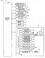
Fig. 17 is a block diagram conceptually illustrating a control device of the electronic circuit assembly apparatus. -
Fig. 18 is a planar view respectively illustrating a state in which holding of the component using a suction nozzle of the component holding head is possible and a state in which the holding is not possible. -
Fig. 19 is a side view illustrating a relationship between the component return device during component return in one of five component supply units and the component holding head of the component delivery device of another component supply unit. -
Fig. 20 is a perspective view illustrating a state in which the component supply system is removed from an assembly apparatus main body with the shuttle device remaining therein. -
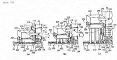
Fig. 21 is a perspective view illustrating a state in which a component tray is provided in place of the component supply unit. -
Fig. 22 is a perspective view illustrating a state in which the component tray is provided in place of two component supply units and illustrating supply of the component using a component packing member. - Applied examples as embodiments of the present invention will be described below with reference to the drawings. Here, in addition to the applied examples below, the present invention is able to be implemented in various forms which carry out various modifications and improvements based on knowledge of a person skilled in the art.
- An electronic circuit assembly apparatus which is one type of automated assembly apparatus is illustrated in
Fig. 1 . The electronic circuit assembly apparatus includes an assembly apparatusmain body 10, a board conveying andholding device 14 which transports and holds a circuit board 12 (hereinafter referred to as a board 12) as a circuit substrate which serves as an assembly target member,component supply systems component mounting device 20,imaging devices Fig. 17 ). Examples of the circuit substrate include a printed-wiring board, a printed-circuit board, a substrate having a three-dimensional shape and the like. The printed-wiring board and the printed-circuit board may be collectively called the circuit board. The electronic circuit assembly apparatus is configured in the same manner as the automated assembly apparatus of the description inJP-A-2011-253869 - The board conveying and
holding device 14 is provided in the center in a front and back direction of the assembly apparatusmain body 10. The board conveying andholding device 14 is provided with aconveyor 30 and aclamping device 32 in the present embodiment, and theboard 12 is transported in a horizontal direction in a horizontal posture. In the present embodiment, the conveyance direction of the board 12 (hereinafter, referred to as a board conveyance direction) is an X-axis direction, a direction in which there is a single horizontal plane on a mounting surface of theboard 12 which is transported using the board conveying and holdingdevice 14 and which is orthogonal to the X-axis direction on the single horizontal plane is a Y-axis direction, and a direction which is orthogonal to the X-axis direction and the Y-axis direction and an up and down direction or a vertical direction is a Z-axis direction. A width direction or a lateral direction of the electronic circuit assembly apparatus is parallel to the X-axis direction, and the front and back direction is parallel to the Y-axis direction. - The
component supply system 16 is provided at the front side of the board conveying and holdingdevice 14. Thecomponent supply system 16 includes a tray-typecomponent supply device 42 which supplies an electronic circuit component (hereinafter referred to as a component) using acomponent tray 40 and a feeder-type component supply device which supplies the component using atape feeder 44 which serves as a component feeder (refer toFig. 17 ). Thecomponent tray 40 is accommodated in atray accommodation device 46, and supplies the component to thecomponent mounting device 20 by moving outside thetray accommodation device 46. Thecomponent supply system 18 will be described in detail below. - The
component mounting device 20 includes workingheads head moving device 54 in the present embodiment, and configures a component receiving section. The workhead moving device 54 is provided with an X-axis-direction moving device 60 (refer toFig. 2 ), a Y-axis-direction moving device 62, and Z-axis-direction moving devices direction moving device 60 and the Y-axis-direction moving device 62, and are moved in the Z-axis direction which are independent from each other respectively using the Z-axis-direction moving devices head moving device 54 is configured by the working heads 50 and 52 such that it is possible to move a region from a component supply section of thecomponent tray 40 and thetape feeder 44 to the rear side of the board conveying and holdingdevice 14. The workinghead 50 in the embodiment is provided with asuction nozzle 70 which sucks and holds the component using negative pressure (refer toFig. 2 ), is set as the mounting head which mounts the component on theboard 12, and for example, the workinghead 52 is provided with a dispenser nozzle (not illustrated) and is set as an adhesive application head which applies an adhesive. Hereinafter, the workinghead 50 is referred to as a mountinghead 50, and the workinghead 52 is referred to as anadhesive application head 52. Theimaging device 22 is moved in the X-axis, Y-axis, and Z-axis directions along with the mountinghead 50. Theimaging device 24 is provided and fixed at a position between the board conveying and holdingdevice 14 of the assembly apparatusmain body 10 and thecomponent tray 40 which supplies the component. - The
component supply system 18 is described. - As shown in
Fig. 1 , thecomponent supply system 18 is detachably attached to a rear section of the assembly apparatusmain body 10 on the rear side of the board conveying and holdingdevice 14. In thecomponent supply system 18, the board conveying and holdingdevice 14 side is the front and the opposite side from the board conveying and holdingdevice 14 side is the rear. As shown inFig. 3 , thecomponent supply system 18 includes a systemmain body 80, acomponent feeder 82, a component dispersedstate realization device 84, acomponent delivery device 86, acomponent return device 88, and animaging device 90. Thecomponent feeder 82, the component dispersedstate realization device 84, and thecomponent return device 88 are assembled in common on aframe 94 to form a set. Hereinafter, the set is referred to as acomponent supply unit 96. At least one, a plurality in the present embodiment, or fivecomponent supply units 96 in the state illustrated and provided, and thecomponent supply units 96 are provided to line up in one row in the lateral direction orthogonal to the front and back direction which is a separation direction of thecomponent feeder 82 and thecomponent mounting device 20 on the systemmain body 80. - As shown in
Fig. 4 , thecomponent feeder 82 includes acomponent accommodation section 100 and acomponent supply section 102. Thecomponent accommodation section 100 is provided above thecomponent feeder 82, has a container form which is open in an upward orientation, and the bottom surface is configured by a pair ofinclined surfaces Fig. 5 , theinclined surfaces opening 108 which passes through in the up and down direction between the lower end sections and extends in the lateral direction. Out of theinclined surfaces inclined surface 104 which is provided on the front surface side of thecomponent feeder 82 has a gentler inclination than theinclined surface 106, and anopening 108 is positioned on a rear section of thecomponent accommodation section 100. Thecomponent supply section 102 is provided with acomponent supply surface 110 which is provided below thecomponent accommodation section 100. Thecomponent supply surface 110 is an inclined surface which is inclined in an orientation facing downward as far forward as possible, and a front edge section which serves as a leading end section configures acomponent discharge section 112. The inclination of thecomponent supply surface 110 is gentler than theinclined surface 104. In addition, a plate form scraping-outmember 114 which extends out downward from thecomponent supply surface 110 is provided on the front end of thecomponent supply surface 110. The dimensions in the front and back direction of theopening 108 slightly increase according to the accommodated component. - As shown in
Fig. 4 , thecomponent feeder 82 is hung from above asupport shaft 122 which is provided on an upper edge of a rear section of aframe 94 by a pair of hooks 120 (onehook 120 is illustrated inFig. 4 ) which are provided on an upper edge of the rear section of thecomponent accommodation section 100, and is supported so as to be able to rotate and be attachable and detachable about a horizontal axis line parallel to the lateral direction. In addition, as shown inFig. 6 , thecomponent feeder 82 is provided such that a plate-form supportedsection 124 protrudes horizontally respectively in lower sections of each front section as a pair of outer surfaces parallel to the front and back direction, is placed on a horizontal plate-form support section 126 which is provided on theframe 94, and is supported from below. For this reason, thecomponent feeder 82 is movable up and down with respect to theframe 94. A state in which thecomponent feeder 82 is supported by theframe 94 is a state in which an angle that is set in advance with respect to the respective horizontal planes of theinclined surface 104 and thecomponent supply surface 110, in the present embodiment is 15 degrees before or after and 10 degrees before and after being inclined, and the scraping-outmember 114 is positioned in a vertical plane. In thecomponent feeder 82, there are a plurality of types in which at least one of the inclination angle of at least one of theinclined surfaces component supply surface 110, and the dimensions of theopening 108 are different, and it is possible to change the type of component which is supplied by thecomponent supply unit 96 by only exchanging thecomponent feeder 82. - As shown in
Fig. 4 , the component dispersedstate realization device 84 includes acomponent support member 150, a component supportmember moving device 152 which serves as a relative moving device which relatively moves thecomponent support member 150 and thecomponent feeder 82, and afeeder vibration device 154. Thecomponent support member 150 includes acomponent support section 156 having a longitudinal plate-shape, and a pair ofleg sections 158. Theleg section 158 is formed in a plate-form, and protrudes up and down at both sides using anupper surface 160 of one plane-form of thecomponent support section 156. The component supportmember moving device 152 includes aslide 164 and a slide driving device 166 (refer toFig. 17 ). Theslide 164 is one type of movable member which is similar to another slide in the description below. Theslide driving device 166 is configured by a rodless cylinder in the present embodiment. - The
component support member 150 is fixed to theslide 164 in a pair ofleg sections 158, and moves a position slightly below the lower end of the scraping-outmember 114 by theslide 164 moving in the front and back direction by guiding to a pair ofguide rails 168 using theslide driving device 166. With respect to thecomponent feeder 82, thecomponent support member 150 is moved in the horizontal direction which is a parallel direction to theupper surface 160, as shown inFig. 4 , is moved to a component supply position at which the entirety of theupper surface 160 is positioned in front of thecomponent feeder 82, and as shown inFig. 6 , to a retraction position at which the front section is positioned below thecomponent feeder 82 and at which the front end of theupper surface 160 is positioned on the front end of thecomponent feeder 82. - As shown in
Fig. 7 , thefeeder vibration device 154 of the present embodiment includes acam member 180, acam follower 182, and astopper 184 which serves as a rotation limit regulation member. Thecam member 180 is formed in a plate form, and is fixed parallel to the front and back direction on one outer surface of a pair ofleg sections 158. A large number ofteeth 190 in thecam member 180 are provided at equal intervals in a direction parallel to the front and back direction. The large number ofteeth 190 are respectively defined by aninclined surface 192 which is inclined in an orientation upward toward the rear and avertical surface 194 which extends out downward in the vertical direction from the upper end of theinclined surface 192, and are configured by thecam surface 196 with a large number of concavities and convexities lined up along a straight line parallel to the front and back direction using theinclined surface 192 and thevertical surface 194. In the present embodiment, as shown inFig. 4 , thecam member 180 is provided in a section in the front and back direction of thecomponent support member 150, and out of theupper surface 160, aportion which corresponds to thecam member 180 functions as acomponent support surface 198 in the front and back direction. - As shown in
Fig. 8 , thecam follower 182 includes alever 202 which is attached to be able to rotate about an axis line parallel to the lateral direction using abracket 200 on the outer surface of thecomponent feeder 82, and aroller 204 which is attached to be able to rotate about the axis line parallel to the lateral direction in a free end section of thelever 202. Thelever 202 biases theroller 204 in an orientation toward the front using atorsion coil spring 206 which serves as a spring member that is one type of biasing means (refer toFig. 9 ). Thestopper 184 is provided on thebracket 200, is formed in a protruding shape, and the rotation limit of thelever 202 is regulated by biasing thetorsion coil spring 206. In a state in which the rotation limit is regulated, as shown inFig. 7 , thecam follower 182 has a posture which protrudes downward from thecomponent feeder 82 in the vertical direction. - The
component return device 88 will be described. - As shown in
Fig. 11 , thecomponent return device 88 of the present embodiment includes the scraping-outmember 114, acomponent collecting container 220, a component collecting container lifting and loweringdevice 222 which serves as a relative lifting and lowering device and amotion conversion mechanism 224. The component collecting container lifting and loweringdevice 222 includes a lifting and loweringmember 226 which is a movable member, and anair cylinder 228 which serves as a lifting and lowering member driving device. Theair cylinder 228 is disposed oriented upward at a position between the pair ofguide rails 168, and is lifted and lowered with respect to thecomponent feeder 82 by the lifting and loweringmember 226 due to expansion and contraction of apiston rod 230. Theair cylinder 228 is formed on the front end section of theslide 164, and the lifting and loweringmember 226 is moved in the front and back direction along with thecomponent support member 150. - The
component collecting container 220 is attached so as to be able to horizontally rotate about a rotation axis parallel to the lateral direction using anaxis 232 in the lifting and loweringmember 226, and is provided to be able to be lifted and lowered to the front end section of thecomponent support member 150. Thecomponent collecting container 220 is lifted and lowered to a lowering end position which is a position below theupper surface 160 of thecomponent support member 150 as shown inFig. 10(a) , and a lifting end position which is positioned above thecomponent feeder 82 as shown inFig. 11 , due to the lifting and lowering of the lifting and loweringmember 226. - In addition, above the lifting and lowering
member 226, thecomponent collecting container 220 is rotated to a component reception position at which the bottom surface is open above a horizontal posture, and a component discharge position at which the component with a vertical posture is discharged to thecomponent feeder 82. Thecomponent collecting container 220 is biased in an orientation that rotates to a component reception position side by a torsion coil spring (not illustrated) which serves as biasing means. The rotation limit of thecomponent collecting container 220 due to the biasing is regulated by a pair ofstoppers 234, and normally thecomponent collecting container 220 is positioned at the component reception position. In addition, arear wall 236 of thecomponent collecting container 220 is inclined in an orientation at a posture downward furthest to the rear at the component discharge position. - As shown in
Figs. 8 and11 , themotion conversion mechanism 224 includes a pair ofrollers 240 which configure an engaged section by providing in thecomponent collecting container 220 and a pair ofengagement surfaces 242 which configure an engaging section by being provided in theframe 94. Oneroller 240 and anengagement surface 242 are illustrated inFigs. 8 and11 . Theroller 240 is attached to be able to rotate about an axis line parallel to the lateral direction in a projecting end section of asupport member 244 that is fixed to protrude out to the rear from thecomponent collecting container 220 which is positioned at the component reception position. Theengagement surface 242 is provided in a portion which corresponds to the upper end section of thecomponent accommodation section 100 of theframe 94, and is a horizontal plane with a downward orientation. - A
shutter 250 is disposed to be able to be lifted and lowered between thecomponent collecting container 220 on a leading end which is the front end of thecomponent support member 150. As shown inFig. 10(c) , the lifting and lowering of theshutter 250 is guided by being engaged to be relatively movable by a protrudingsection 254 which is provided on the leading end of theslide 164 on a pair oflong holes 252. In addition, theshutter 250 is biased above by acompression coil spring 255 as biasing means that is engaged with a pair ofrods 253 that are erected on theslide 164. An upper limit of theshutter 250 due to biasing is regulated by the lower end section of thelong hole 252 abutting the protrudingsection 254, and in this state, theshutter 250 protrudes above thecomponent supply surface 110 of thecomponent supply unit 96, and is positioned at a shielding position which prevents the component from falling from thecomponent supply surface 110. In a state in which thecomponent collecting container 220 is positioned at the lowering end position, as shown inFig. 10(a) , an engagingsection 256 with a protruding shape which is provided on a rear end section of the lifting and loweringmember 226 abuts from above an engagedsection 258 with the protruding shape which is provided on a lower end section of theshutter 250, theshutter 250 is lowered opposing biasing force of thecompression coil spring 255, and is positioned at a non-shielding position which is positioned below theupper surface 160 of thecomponent support member 150. - The
imaging device 90 is described based onFig. 3 . - For example, the
imaging device 90 is provided with a CCD camera or a CMOS camera which serves as an imager, images a section of theupper surface 160 of thecomponent support member 150 in the front and back direction, and has a field of view in which it is possible to image the entirety of theupper surface 160 in the lateral direction. An imagingdevice moving device 270 includes aslide 272 and aslide driving device 274 in the present embodiment (refer toFig. 17 ) . Theslide driving device 274 includes anelectric motor 276 which serves as a driving source and afeeding screw mechanism 278. The feedingscrew mechanism 278 includes anut 280 and afeeding screw 282, theslide 272 is guided to aguide rail 284 and is moved to an arbitrary position in the lateral direction by a feedingscrew 282 being rotated by theelectric motor 276. Theimaging device 90 is provided on theslide 272, is not moved in the front and back direction, and is moved only in the lateral direction. It is desirable that theelectric motor 276 is a servomotor which is a type of electric rotary motor which is able to carry out accurate control of the rotation angle, and it is desirable that the feeding screw mechanism is a ball screw mechanism. It is possible to adopt a stepping motor or a linear motor as the electric motor. Another electric motor and feeding screw mechanism are described below in the same manner. - In the present embodiment, the
component support surface 198 is slightly smaller than the field of view of theimaging device 90 in the front and back direction, and the lateral direction is the size of the entirety of theupper surface 160. The length of thecam member 180 is set in combination with the height in the front and back direction of thecomponent support surface 198. Theimaging device 90 is disposed in a downward orientation above thecomponent support surface 198 of thecomponent support member 150 which is positioned at the component supply position, and is disposed at a posture which faces thecomponent support surface 198. Theimaging device 90 is moved by the imagingdevice moving device 270, selectively faces each of the component support surfaces 198 of thecomponent supply unit 96 of five sets, and images a plurality of components on eachcomponent support surface 198 at each of the five imaging positions. Here, the component support surface may be larger than the field of view of the imaging device. This is because, a component which is located on the component support surface and whose entire image cannot be obtained because only a portion of which is positioned within the field of view, as well as a component whose image cannot be obtained because the entire portion of which is positioned outside of the field of view, is determined not to be appropriate for holding, and therefore such a component is not picked up from the component support surface. Alternatively, the imaging device moving device maybe an apparatus which moves the imaging device also in the front and back direction, and image the entirety of the component support surface. - The
component delivery device 86 is described based onFig. 12 . - The
component delivery device 86 in the present embodiment includes acomponent holding head 300, a component holdinghead moving device 302, and one or more, for example, a plurality, twoshuttle devices Fig. 3 ). The component holdinghead moving device 302 includes an X-axis-direction moving device 320, a Y-axis-direction moving device 322, and a Z-axis-direction moving device 324, and thecomponent holding head 300 is moved in each direction of the X axis, the Y axis, and the Z axis. The X-axis direction and the Y-axis direction are a first direction and a second direction which are orthogonal to each other in parallel to thecomponent support surface 198, and the Z-axis direction is a third direction orthogonal to thecomponent support surface 198. The Y-axis-direction moving device 322 is provided on the systemmain body 80 and includes a Y-axis slide 326 and a Y-axisslide driving device 328. The Y-axisslide driving device 328 is provided with anelectric motor 330 and afeeding screw mechanism 336 which includes afeeding screw 332 and anut 334, and moves to an arbitrary position in the Y-axis direction while guiding the Y-axis slide 326 on a pair of guide rails 338. - The X-axis-
direction moving device 320 is provided on the Y-axis slide 326, and includes anX-axis slide 340 and an X-axisslide driving device 342. The Z-axis-direction moving device 324 is provided on theX-axis slide 340, and includes a Z-axis slide 344 and a Z-axisslide driving device 346. The X-axisslide driving device 342 and the Z-axisslide driving device 346 are configured in the same manner as the Y-axisslide driving device 328, and a corresponding relationship is indicated by giving the same reference numerals in the configuration elements which have the same function, and description is omitted. - The
component holding head 300 is provided on the Z-axis slide 344. The component holdinghead moving device 302 is provided with thecomponent holding head 300 in the Z-axis-direction moving device 324, and so as to move the height between theimaging device 90 and thecomponent support surface 198. In the region in the height direction, thecomponent holding head 300 is moved to an arbitrary position in the horizontal direction and the vertical direction. Accordingly, theimaging device 90 and thecomponent holding head 300 are able to be positioned simultaneously on thecomponent support surface 198 of the samecomponent supply unit 96, and thecomponent holding head 300 is positioned above thecomponent support surface 198 due to movement in at least one of the X-axis direction and the Y-axis direction and movement in the horizontal direction, and the component on thecomponent support surface 198 is moved to a function position at which the component is able to be held and a retraction position which is retreated from the function position. As shown inFig. 13 , thecomponent holding head 300 includes a headmain body 360 which is provided integrally with the Z-axis slide 340, asuction nozzle 362 which serves as a component holding tool, anozzle rotation device 364 which serves as a holding tool rotating device and anozzle pivoting device 366 which serves as a holding tool pivoting device. Here, other than a suction nozzle, for example, a plurality of gripping members are provided in the component holding tool, and it is possible to adopt a component gripper which grips and releases the component by the gripping members being moved relative to each other. - The
nozzle pivoting device 366 includes alinking mechanism 370 and a linkingmechanism driving device 372. The linkingmechanism driving device 372 includes a lifting and loweringmember 374 which serves as a driving member and a lifting and loweringmember driving device 376. The lifting and loweringmember driving device 376 is provided with anelectric motor 378, and afeeding screw mechanism 384 which includes afeeding screw 380 and anut 382, transmits rotation of theelectric motor 378 to thefeeding screw 380 using timing pulleys 386 and 388 and atiming belt 390, and is lifted and lowered by the lifting and loweringmember 374. Aspline shaft 392 is attached to the lifting and loweringmember 374 in an orientation which extends out vertically below. One end section of alever 394 is attached to be able to rotate about the horizontal axis line on the lower end section of thespline shaft 392 using ashaft 395, and thesuction nozzle 362 is detachably held using anozzle holding member 396 which serves as a component holding tool holding member that is provided on thelever 394. - In the
lever 394, anarm 400 protrudes in an orientation which sterically intersects orthogonal to the rotation axis of thelever 394, and in a projecting end section thereof, a pair ofrollers 402 is configured by the cam follower to be attached to be able to rotate about the axis line which is parallel to the rotation axis of thelever 394. The pair ofrollers 402 are respectively engaged with a pair of horizontallong holes 406 of thecam member 404 which is provided to be immovable in the up and down direction on the headmain body 360. As shown inFig. 13(a) , in a state in which the lifting and loweringmember 374 is positioned at the lifting end position, in thesuction nozzle 362, the axis line is positioned at the non-pivoting position concentric with thespline shaft 392. When the lifting and loweringmember 374 is lowered, thelever 394 is rotated due to the lowering of theroller 402 being prevented by thecam member 404, and thesuction nozzle 362 is pivoted about a horizontal pivot axis line. In a state in which the lifting and loweringmember 374 is lowered to the lowering end position, thesuction nozzle 362 is pivoted 90 degrees and the axis line is horizontal. The non-pivoting position and the 90 degree pivoting position are determined by positional control of the lifting and loweringmember 374 due to control of theelectric motor 378. Thesuction nozzle 362 is also able to be held at an arbitrary pivoting position between the non-pivoting position and the 90 degree pivoting position. - The
nozzle rotation device 364 includes anelectric motor 410 and arotation transmitting device 412 which are attached via a not-illustrated attachment member in the headmain body 360. Therotation transmitting device 412 includes agear 414 which is attached to an output shaft of theelectric motor 410 and agear 418 fixed in aspline member 416 that is engaged with thespline shaft 392 to be relatively unrotatable and relatively movable in an axial direction, and thespline shaft 392 is rotated at an arbitrary angle in both forward and reverse directions about a vertical axis line. Rotation is transmitted to thespline shaft 392 at some position in the up and down direction, and thesuction nozzle 362 is able to rotate at an arbitrary angle about the vertical axis line which is an axis line that is orthogonal to the horizontalcomponent support surface 198. It is possible to fix thecam member 404 to thespline member 416, rotate thecam member 404 with thespline shaft 392 and thesuction nozzle 362, and pivot thesuction nozzle 362 even in a state of positioning at any rotation position. - In the
suction nozzle 362, there are a plurality of different types of dimensions and shapes of a suction surface of a suction pipe, and the type ofsuction nozzle 362 is used according to the type of supplied component. For this reason, as shown inFig. 3 , in the systemmain body 80, anozzle accommodation device 430 which accommodates a plurality of types ofsuction nozzles 362 is provided. Thecomponent holding head 300 is moved to thenozzle accommodation device 430 according to need, and thesuction nozzle 362 is automatically exchanged according to the type of component which is supplied by five sets ofcomponent supply units 96. - As shown in
Fig. 3 , theshuttle devices component carriers carrier moving devices component supply unit 96 of the systemmain body 80. In the present embodiment, each of thecomponent carriers component receiving member 460 to configure a component receiving section. As shown inFig. 14 , thecomponent receiving member 460 is engaged in a recessedsection 462 of thecomponent carriers sections component carriers component receiving member 460, a plurality in the present embodiment, for example, five in a state of being lined up in a row in the lateral direction. - An example of the component which is supplied by the
component supply system 18 is an electronic circuit component with a lead, such as, for example, acomponent 480 illustrated inFig. 16 which includes a componentmain body 482 having a block shape and one or plural leads 484 (two leads in the case of the illustrated component 480) protruding from one side surface of the componentmain body 482. The electronic circuit component with a lead is an example of a component which is provided with a protruding section which protrudes from one surface and to be inserted in a concave section of an assembly target member. Four side surfaces 486 which are parallel to thelead 484 of the componentmain body 482 are orthogonal to each other, and in a case of being located on a horizontal support surface in eachside surface 486, are able to be stationary in a posture in which thelead 484 is horizontal. In addition, three out of fourside surfaces 486 configure a suction surface which closes the opening of the suction pipe of thesuction nozzle 362 and has an area which is able to be sucked by preventing leakage of negative pressure, but as shown inFig. 16(b) , oneindentation 488 is provided, the surface area is not sufficient to close the opening of the suction pipe, and suction is not possible. - As shown in
Fig. 14 , a component receivingrecess section 500 is provided on thecomponent receiving member 460. The componentreceiving recess section 500 is provided according to the shape and dimensions of the received component, the component receivingrecess section 500 of thecomponent receiving member 460 into which the electronic circuit component with a lead is inserted is, for example, formed in a step shape as shown inFig. 15 (a) , and includes a main body section receiving recessedsection 502 which opens to the upper surface of thecomponent receiving member 460 and a leadreceiving recess section 504 which opens to the bottom surface of a main body section receiving recessedsection 502. On an opening end section of the main body section receiving recessedsection 502, Chamfering is performed, aguide surface 506 which guides engagement of the component is formed, and is configured by a guide section. As shown inFig. 15 (b) , thecomponent 480 is accommodated by thelead 484 on the lead receivingrecess section 504 in a posture in a downward orientation using thecomponent receiving member 460, positionally aligns themain body section 482 in the horizontal direction by engaging with the main body section receiving recessedsection 502, is supported from below using acomponent support surface 508 with an upward orientation which is conf igured by the bottom surface of the main body section receiving recessedsection 502, and is received in a state of positional alignment in the up and down direction. - As exemplified in
Fig. 14 , there are a plurality of different types of dimensions and shapes of the component receivingrecess section 500 in thecomponent receiving member 460, and are exchanged by the operator. It is also possible to hold a component receiving member which has a plurality of dimensions of thecomponent receiving member 460 on thecomponent carriers - As shown in
Fig. 3 , each moving devicemain body 520 of the componentcarrier moving devices main body 80, and is provided with anendless belt 522 and a belt rotation device 524 (refer toFig. 17 ). The componentcarrier moving devices belt 522 is wound onto a plurality of pulleys (not illustrated) which is provided to be able to be rotated about the axis line parallel to the lateral direction in the moving devicemain body 520, and is locked to thecomponent carrier 450. Thebelt 522 is rotated by rotating the pulley using the electric motor 528 (refer toFig. 17 ), and thecomponent carrier 450 is guided to a pair of guide rails 530 (oneguide rail 530 is illustrated inFig. 3 ), and is moved in the front and back direction. Thecomponent carriers component holding head 300, close to the component holdinghead moving device 302, and adjacent to thecomponent supply unit 96, and a component delivery position which is positioned in a rear section of the movement region of the mountinghead 50, and close to thecomponent mounting device 20. Thecomponent carriers main body 520. - The
integrated control device 26 configures a computer as a main body. As shown inFig. 17 , in the electronic circuit assembly apparatus of the present embodiment, the board conveying and holdingdevice 14 and the like are each individually provided in the control device, the driving source and the like of each device is controlled, and imaging data of theimaging devices component supply system 18 is also provided with anindividual control device 550, theslide driving device 166 or the like is controlled, and data which is obtained by imaging of theimaging device 90 is processed by animage processing device 552. Theintegrated control device 26 integrally controls the individual control devices. - Next, an operation is described.
- The
board 12 is conveyed to the electronic circuit assembly apparatus using theconveyor 30 and clamping using theclamping device 32 by stopping in an assembly position during electronic circuit assembly. Then, the mountinghead 50 is moved, and the component which is supplied using thecomponent supply systems board 12. - Supply of the component using the
component supply system 18 will be described. In the present embodiment, the component which is supplied using five sets ofcomponent supply units 96 being some electronic circuit component with a lead, and is denoted by thereference numeral 480. Component supply actions by thecomponent supply units 96 are the same, and one is described. - A plurality of
components 480 are putted in thecomponent accommodation section 100 of thecomponent feeder 82. During component inputting, as shown inFig. 6 , thecomponent support member 150 is positioned at the retraction position. Some of the input components passes through theopening 108 and is lowered onto thecomponent supply surface 110, is moved to thecomponent discharge section 112 side due to the inclination of thecomponent supply surface 110, and is spread on thecomponent supply surface 110. In a state in which thecomponent 480 is clogged and theopening 108 is blocked, the lowering of the component to thecomponent supply surface 110 is stopped, and a plurality of thecomponents 480 are accommodated in thecomponent accommodation section 100 in a bulk state with a random posture. Even if thecomponent 480 which is lowered onto thecomponent supply surface 110 moves beyond thecomponent discharge section 112, thecomponent 480 is accommodated in thecomponent collecting container 220. Thecomponent collecting container 220 is positioned at the retraction position along with thecomponent support member 150, and is positioned at the lowering end position along with the component reception position. - After component inputting, the
component support member 150 advances, and slips out from below to in front of thecomponent feeder 82. If thecam member 180 reaches thecam follower 182, theroller 204 is lifted along theinclined surface 192 of theteeth 190, and if reaching thevertical surface 194, the roller is lowered and rides over theteeth 190. Thecam follower 182 is biased in an orientation to mesh with theteeth 190 using the torsion coil spring and regulates the rotation limit using thestopper 184, during advancing of thecomponent support member 150, theroller 204 is maintained in the state of meshing with theteeth 190, as shown inFig. 7 , thelever 202 does not rotate, and thecam follower 182 rides over theteeth 190 along with thecomponent feeder 82. Thecam follower 182 rides over a plurality of theteeth 190 one at a time, the front section of thecomponent feeder 82 is lifted up by repeating lifting, and vibrated in the up and down direction. At this time, lifting from thesupport shaft 122 of thecomponent feeder 82 is avoided due to own weight. - The component on the
component supply surface 110 moves forward due to vibration and an inclination of thecomponent supply surface 110, and as shown inFig. 7 , is discharged from thecomponent discharge section 112 on thecomponent support surface 198. At this time, lowering of thecomponent 480 is prevented due to the pair ofleg sections 158 which protrude above theupper surface 160. In addition, thecomponent 480 in which theopening 108 is blocked is broken up and is lowered on thecomponent supply surface 110 due to vibration of thecomponent feeder 82, and thecomponent 480 in thecomponent accommodation section 100 passes through theopening 108 and is lowered on thecomponent supply surface 110 and discharged. Accompanying the advancing of thecomponent support member 150, a different portion of thecomponent support surface 198 sequentially corresponds to thecomponent discharge section 112, the area of thecomponent support surface 198 increases, and sequentially, thecomponent 480 is supported. The advancing direction of thecomponent support member 150 is a positive direction, and a retreat direction is a reverse direction, during advancing of acomponent support member 160, thecomponent feeder 82 is vibrated only in a period in which thecam follower 204 rides over thecam member 180, and thecomponent 480 is discharged from thecomponent discharge section 112. Thecam member 180 is separated from acam follower 182 before thecomponent support member 150 reaches the component supply position, thecomponent support member 150 is advanced, but thecomponent feeder 82 is not vibrated, and the component is not discharged. For this reason, a state in which thecomponent support member 150 reaches the component supply position is a state in which in theupper surface 160, thecomponent 480 is dispersed in only thecomponent support surface 198. - After the
component support member 150 stops, theimaging device 90 is moved, and a plurality of thecomponents 480 which is dispersed on thecomponent support surface 198 is imaged all at once. Based on the imaging data, the component of a state which is appropriate to hold using thesuction nozzle 362 is determined to be a holding target component. For example, if the holding target component is thecomponent 480 in the illustration inFig. 16 , as shown inFig. 18 (a) , thelead 484 is isolated from anothercomponent 480 in a posture which extends in a direction parallel to thecomponent support surface 198, and aside surface 486 on which suction by thesuction nozzle 362 is possible has a posture facing upward. In contrast to this, as exemplified inFig. 18 (b) , thecomponent 480 of an inclined state or thelead 484 is parallel to thecomponent support surface 198, but thecomponent 480 of the posture at which theside surface 486 on which suction is not possible faces upward is not appropriate in holding, and a non-holding target component is set. Posture model data of the holding target component is formed in advance for each type of component, is stored in a posture model data memory which is provided in a RAM of a computer constituting a main part of theindividual control device 550 and configures storage means, and the posture model data is compared with posture data of the component which is obtained by imaging. - During imaging, the
component holding head 300 is positioned at the retraction position, and imaging of the component is permitted by theimaging device 90. After imaging, thecomponent holding head 300 is moved to the function position, and after imaging by theimaging device 90, the holding target component is held on thecomponent support surface 198 which maintains a stationary state of stopping without change. In a case where there are a plurality of holding target components, the components are held one by one according to an order set in advance. For example, the order is an order of holding from the component which is positioned on the frontmost side in the front and back direction, and positioned furthest on the downstream side in the board conveyance direction in the lateral direction. Since thecomponent holding head 300 moves a height region between theimaging device 90 and thecomponent support surface 198, after imaging, theimaging device 90 may not retreat from above thecomponent support surface 198 when thecomponent holding head 300 holds the component. In addition, theimaging device 90 is able to move to the function position of thecomponent holding head 300 or move on thecomponent support surface 198 of anothercomponent supply unit 96 in parallel to a component holding operation. - Each position and rotation position (position about the axis line) in the X-axis and Y-axis directions of the holding target component is acquired based on imaging of the
imaging device 90. Thecomponent holding head 300 is moved and lowered to the acquired position, and thecomponent 480 is sucked and picked up due to negative pressure by thesuction nozzle 362. After suction of the component, thesuction nozzle 362 is moved to the component carrier which is positioned at the component receiving position. During suction of the component, thesuction nozzle 362 is positioned at the non-pivoting position, is pivoted to the 90 degree pivoting position during movement of the component carrier, and thelead 484 is orientated downwards. However, since the pivot direction is determined in one direction, prior to suction of thecomponent 480, thesuction nozzle 362 is rotated about the own axis line in a state of position at the non-pivoting position, a vertical pivot plane of thesuction nozzle 362 is parallel to the vertical plane parallel to a longitudinal direction of thelead 484 of thecomponent 480 which is located on thecomponent support surface 198, and thelead 484 is positioned at the rotation position orientated downward due to pivoting. - In addition, after suction of the component, the
suction nozzle 362 is rotated about the axis line of thespline shaft 392, and the rotation phase about a vertical line of the componentmain body 482 matches the rotation phase of the main body section receiving recessedsection 502. Thecomponent holding head 300 is lowered on the component receivingrecess section 500, thecomponent 480 is guided to theguide surface 506 and is received on the component receivingrecess section 500. After this, thecomponent 480 is released by cutting supply of negative pressure to thesuction nozzle 362, thecomponent holding head 300 is lifted, and thesuction nozzle 362 is pivoted and is returned to the non-pivoting position. - The component imaging by the
imaging device 90 is performed in advance in holding in each holding of thecomponent 480 using thecomponent holding head 300, and thecomponent 480 is sucked on thecomponent support surface 198 by thesuction nozzle 362, then imaging is performed concurrent to receiving in the component receivingrecess section 500. When a plurality of thecomponents 480 are discharged continuously from the samecomponent supply unit 96, theimaging device 90 is positioned without change on thecomponent support surface 198 of thecomponent supply unit 96, thecomponent holding head 300 in which thecomponent 480 is held retreats, then imaging is performed. Thereby, for example, if a position and posture of thecomponent 480 which is to be held subsequently by holding theformer component 480 in onecomponent supply unit 96 are changed, or even if the holding target component is in a non-holding target component, the change is acquired, and the holding target component is reliably held. Here, when thecomponents 480 are picked up from anothercomponent supply unit 96, theimaging device 90 performs imaging by moving above thecomponent supply unit 96. - The
component holding head 300 reciprocally moves between thecomponent carriers component support surface 198, the component is selectively picked up from fivecomponent supply units 96 and is held in thecomponent carrier 450 or thecomponent carrier 452. When thecomponents 480 are received in all of thecomponent receiving members 460 of the component carrier which is positioned at the component receiving position, the component carrier is moved to the component delivery position. The mountinghead 50 of thecomponent mounting device 20 is moved to the component carrier which is positioned at the component delivery position, and the component on thecomponent receiving member 460 is sucked by thesuction nozzle 70 and picked up. Thecomponent 480 is accommodated in thecomponent receiving member 460 in a state in which thelead 484 is oriented downward and the suctionable side surfaces 486 are upper surfaces, and it is possible for thesuction nozzle 70 to reliably suck thecomponent 480. - After a component is picked up, the mounting
head 50 is moved to theimaging device 24, and thecomponent 480 which is held in thesuction nozzle 70 is imaged. Based on the imaging data obtained as a result of imaging, a phase difference between a rotation phase about the vertical line of thecomponent 480 and a mounting phase of thecircuit board 12, and a holding position error of thecomponent 480 using thesuction nozzle 70 are calculated, and both are corrected and thecomponent 480 is mounted on theboard 12. Thelead 484 is inserted in a lead insertion hole of theboard 12, and thecomponent 480 is attached on theboard 12. When thecomponents 480 are picked up from all of thecomponent receiving members 460 of the component carrier which is positioned at the component delivery position, the component carrier is moved to the component receiving position. Two component carriers are provided, and it is possible to perform reception of the component and delivery of the component concurrently using the component carrier. For this reason, there is no time at which the mountinghead 50 waits for movement to the component delivery position of the component carrier, or the waiting time is short, and reduction of the component mounting efficiency is avoided or suppressed. - Here, other than the
imaging device 24, the imaging device may be provided in order to acquire a holding state (rotation phase about the vertical line and holding position error) using the component holding tool of a component which is supplied by thecomponent supply system 18. For example, the imaging device is provided in a portion at a rear side using the board conveying and holdingdevice 14 of the assembly apparatusmain body 10, the component is picked up from the component carrier by the mountinghead 50, then is moved to the imaging device and the component is imaged. - If there is no holding target component on the
component supply unit 96, the component supply of thecomponent support surface 198 is performed. Presence or absence of the holding target component is determined based on imaging data, and if not present, thecomponent support member 150 retreats to the retraction position. At that time, if there is acomponent 480 which remains on thecomponent support surface 198 which is not determined in the holding target component, thecomponent 480 is returned to thecomponent feeder 82 using thecomponent return device 88. The main returnedcomponent 480 is thecomponent 480 which remains on thecomponent support surface 198 as the component in a state which is not appropriate in holding by thesuction nozzle 362, but when planned assembly work ends, thecomponent 480 which remains in thecomponent support surface 198 may also be returned. - As shown in
Fig. 8 , thecomponent 480 which remains on thecomponent support surface 198 is moved forward with respect to thecomponent support member 150 by hindering retreat using the scraping-outmember 114, and is scraped away in thecomponent collecting container 220. During retreat of thecomponent support member 150, force acts in the same direction as the retreat direction of thecomponent support member 150 to thecam follower 182 from thecam member 180, but thestopper 234 permits free rotation in the direction of thecam follower 182. Thereby, as shown inFigs. 8 and 9 , thecam follower 182 rides over theteeth 190 by rotating with respect to thecomponent feeder 82 opposing biasing force of thetorsion coil spring 206, and thecomponent feeder 82 is not vibrated, and thecomponent support member 150 is retreated. For this reason, the component does not fall from thecomponent accommodation section 100 on thecomponent supply surface 110, and is not also discharged to thecomponent support surface 198. - As shown in
Fig. 10(a) , after movement to the retraction position of thecomponent support member 150, as shown inFig. 10(b) , thecomponent collecting container 220 is lifted with respect to thecomponent feeder 82. Theshutter 250 is lifted due to biasing of thecompression coil spring 255 accompanying lifting of thecomponent collecting container 220, and as shown inFig. 10(c) , in the shielding position, thecomponent discharge section 112 is blocked. Theroller 240 is lifted along the outer surface of thecomponent feeder 82 along with thecomponent collecting container 220. After thecomponent collecting container 220 is moved to the shielding position of theshutter 250, thecomponent collecting container 220 is further lifted, and the end of lifting movement at which thecomponent collecting container 220 is lifted in the vicinity of the lifting end position, as shown inFig. 11 , theroller 240 abuts theengagement surface 242 and lifting is prevented. Thereby, thecomponent collecting container 220 is rotated to the component discharge position opposing the biasing force of the torsion coil spring during further lifting up to the lifting end position, and the recoveredcomponent 480 is discharged in thecomponent accommodation section 100. A state in which thecomponent collecting container 220 is rotated to the component discharge position is a state in which the bottom surface is vertical, and therear wall 236 faces thecomponent accommodation section 100 downward, and thecomponent 480 is discharged to thecomponent accommodation section 100 without remaining by being guided to therear wall 236. - Also during performance of returning of the component to the
component feeder 82 in any of the fivecomponent supply units 96, it is possible to perform imaging and holding of thecomponent 480 of anothercomponent supply unit 96 using theimaging device 90 and thecomponent holding head 300. As shown inFig. 19 , with respect to performing return of the component in a state in which thecomponent support member 150 is returned to the retraction position, thecomponent support surface 198 is provided on the front section side of thecomponent support member 150, without interfering with thecomponent collecting container 220, imaging and holding of thecomponent 480 on thecomponent support surface 198 is performed. - The
component supply system 18 is able to be removed from the assembly apparatusmain body 10. In the present embodiment, as shown inFig. 20 , thecomponent supply system 18 removes theshuttle devices main body 10, and maintenance is performed from the rear section side of the assembly apparatusmain body 10. During attachment of the assembly apparatusmain body 10 of a portion which is removed from thecomponent supply system 18, matching of each position of the portions of the X axis, the Y axis, and the Z-axis directions is performed, but since theshuttle devices component mounting device 20, positional alignment is easy accompanying attachment and removal of thecomponent supply system 18. In this meaning, theshuttle devices component supply system 18, and it is also possible to consider that there are configuration elements of the component mounting device. In that case, theshuttle devices - Here, the
shuttle devices main body 10 along with thecomponent supply unit 96 and the like. - In addition, by the
component feeder 82 hangs and releases thehook 120 on thesupport shaft 122, it is possible to easily remove and exchange theframe 94, and it is possible to easily correspond to change over and the like by exchanging only thecomponent feeder 82 of thecomponent supply unit 96. Here, the component feeder may attach and detach only the component accommodation section from the frame, and the component supply section may be shared with a plurality of component accommodation sections. - As apparent from the above description, in the present embodiment, imaging is performed in the
imaging device 90 of theindividual control device 550, the holding target component is determined based on the imaging result, and a portion which is held in thesuction nozzle 362 is configured by an imaging and holding control section. - As shown in
Fig. 21 , a handplacement component tray 600 which serves as a hand placement component support member may be provided to be attachable and detachable in place of thecomponent supply unit 96. The handplacement component tray 600 provides a one plane-formcomponent support surface 602, and after attachment of the systemmain body 80, alternatively, prior to attachment, thecomponent 604 is placed outside of the component supply system by an operator. Supply of the component which is used in such a hand placement component tray is appropriate in supply of a component in which the lead which tends to bend, a component which is not to come into contact with other components, a component to which applying vibration is not desirable, a large component, and the like. - As shown in
Fig. 22 , a handplacement component tray 610 may have a plurality of dimensions of thecomponent supply unit 96 in the lateral direction. In addition, in the front and back direction, the hand placement component tray may have a larger dimension than the field of view of theimaging device 90, and the entirety of the upper surface may be the component support surface. In the case of the latter, the imaging device moving device also moves the imaging device in the front and back direction. Furthermore, acomponent 612 may be supplied by packing without change during shipping. Thecomponent packing member 614 in which a plurality of thecomponents 612 are aligned and accommodated for shipping is set in a component tray, and thecomponent 612 is supplied. In a case where conditions match in supply of the component using thecomponent packing member 614, for example, in a case where thecomponent packing member 614 has a settable size in a component tray, a case where thecomponent 612 is packaged in a posture in which suction is possible using thesuction nozzle 362, and the like are possible. - The component receiving section of the automated assembly apparatus may be equivalent to the component carrier which is at the component delivery position. In this case, the automated assembly apparatus is included an object (movable object or fixed object) which is equivalent to the component carrier on which is at the component delivery position, and the component supply system includes only a portion in which the components on the component support surface of the component delivery device are picked up one at a time using a component holding tool.
- In the component delivery device, the shuttle device is omitted, and in place of the component carrier, a component accommodation member may be provided which positionally aligns and accommodates a plurality of components at a fixed position equivalent to the component carrier.
- The feature in which the component, which is accommodated in the component feeder, is a component which is provided with a protruding section that protrudes from one surface and is to be inserted in a concave section of an assembly target member, and an imaging and holding control section determines the component, which is isolated from another component in a posture in which the protruding section extends in a direction parallel to the component support surface on the component support surface, to be the holding target component, is particularly advantageous when the feature is adopted in combination with a feature in which the component delivery device includes the holding tool rotating device and the holding tool pivoting device. However, the invention is not limited to this configuration. For example, if the mounting device of the automated assembly apparatus includes the holding tool rotating device and the holding tool pivoting device, even if the component delivery device of the component supply system according to the present invention does not include the holding tool rotating device and the holding tool pivoting device, it is possible to adopt a characteristic in which the holding target component as above is determined.
- It is not necessary to perform imaging of the component support surface prior to holding every time the component holding tool holds the component, and may be performed only once on one component support surface.
- In addition, the component is not limited to a component which is provided with the protruding section which is to be inserted in the concave section of the assembly target member, but may be a component in which the protruding section is not provided.
- The component feeder may have only the component accommodation section. For example, the
inclined surface 106 on the rear side of thecomponent feeder 82 is an inclined surface which extends to a front end of the component feeder, the lower end section of the inclined surface is set as the component discharge section and the component on the component support surface is discharged. - The entirety of the upper surface of the component support member may be the component support surface. In this case, according to need, the imaging device moving device moves the imaging device in the lateral direction and the front and back direction.
- Each characteristic of the component supply system according to the present invention, for example, each characteristic below is able to be adopted independently from other characteristics. That is, (1) the control device includes the imaging and holding control section which causes the imaging device to image in a state in which the component support surface is maintained in a stationary state, and causes the component delivery device to hold the holding target component using the component holding tool; (2) the imaging device is disposed above the component support surface at a posture at which the imaging device faces the component support surface, and the component delivery device includes the holding tool moving device which moves the component holding tool to the function position at which the component holding tool is able to hold the component on the component support surface and the retraction position which is retreated from the function position, in a height space between the imaging device and the component support surface; (3) the component supply system includes a plurality of the component feeders and a plurality of the component support surfaces, in which a plurality of the component feeders and a plurality of the component support surfaces are disposed to line up in a lateral direction, and the imaging device moving device which moves the imaging device in the lateral direction to selectively face each of a plurality of the component support surfaces; (4) the imaging device moving device does not move the imaging device in the front and back direction, and the imaging device images a plurality of the components on the component support surface in each of a plurality of the imaging positions at which the imaging device faces each of a plurality of the component support surfaces; (5) the component dispersed state realization device includes the component support member, the relative moving device which relatively moves the component support member and the component feeder in a direction parallel to the component support surface, and the container vibration device; (6) the component delivery device includes the holding tool moving device and the component carrier; (7) the component delivery device includes the holding tool rotating device and the holding tool pivoting device; (8) the component supply system includes the component return device; (9) the component supply system includes a hand placement component support member; and the like.
- The component supply system according to the present invention can be adopted in an electronic circuit component mounting machine which is modularized in a manner described in
JP-A-2004-104075 - 18: COMPONENT SUPPLY SYSTEM, 20: COMPONENT MOUNTING DEVICE, 82: COMPONENT FEEDER, 84: COMPONENT DISPERSED STATE REALIZATION DEVICE, 86: COMPONENT DELIVERY DEVICE, 88: COMPONENT RETURN DEVICE, 90: IMAGING DEVICE, 154: FEEDER VIBRATION DEVICE, 198: COMPONENT SUPPORT SURFACE, 220: COMPONENT COLLECTING CONTAINER, 364: NOZZLE ROTATION DEVICE, 366: NOZZLE PIVOTING DEVICE, 450, 452: COMPONENT CARRIER
Claims (9)
- A component supply system (18) which is configured to supply components (480) in a bulk state to a component receiving section (20) of an automated assembly apparatus in a predetermined posture, the system (18) comprising:a component feeder (82) which is configured to accommodate a plurality of components (480) in the bulk state in a random posture, and is configured to supply the accommodated components (480);a component dispersed state realization device (84) which is configured to realize a state where a plurality of the components (480) within the component feeder (82) are dispersed on a flat component support surface (198) of a component support member (150);a component delivery device (86) which is configured to pick up the components (150) on the component support surface (198) one at a time using a component holding tool (362) and is configured to deliver the components (480) to the component receiving section (20);an imaging device (90) which is configured to image a plurality of the components (480) which are dispersed on the component support surface (198); anda control device (550) which is configured to control the component supply system (18),wherein the control device (550) includes an imaging and holding control section which is configured to cause the imaging device (90) to perform the imaging and is configured to cause the component holding tool (362) to hold the components (480) in a state in which the component support surface (198) is maintained in a stationary state, in such a manner that the component holding tool (362) holds a component (480) in a state that is appropriate for holding by the component holding tool (362) as a holding target component from among a plurality of the components (480) which are dispersed on the component support surface (198) based on the result of imaging by the imaging device (90)wherein the component delivery device (86) includes:a holding tool rotating device (364) which is able to rotate the component holding tool (362) at an arbitrary angle about a rotation axis line orthogonal to the component support surface (198), anda holding tool pivoting device (366) which is able to pivot the component holding tool (362) about a pivot axis line orthogonal to the rotation axis line, andthe component delivery device (86) is configured to rotate about the rotation axis line and is configured to pivot about the pivot axis line a component (480) which is picked up from the component support surface (198) by the component holding tool (362),characterized in thatthe component supply system (18) comprises a plurality of the component feeders (82) and a plurality of the component support surfaces (198),
wherein a plurality of the component feeders (82) and a plurality of the component support surfaces (198) are respectively disposed to line up in a lateral direction orthogonal to a front and back direction which is a separation direction of the component feeders (82) and the component receiving section (20), andthe component supply system (18) further comprises an imaging device moving device (270) which is configured to move the imaging device (90) in the lateral direction so that the imaging device (90) selectively faces each of a plurality of the component support surfaces (198). - The component supply system (18) according to claim 1,
wherein the imaging device (90) is disposed above the component support surface (198) at a posture at which the imaging device (90) faces the component support surface (198), and the component delivery device (86) includes a holding tool moving device (302) which is configured to move the component holding tool (362) to a function position at which the component holding tool (362) is able to hold the component (480) on the component support surface (198) and a retraction position to which the component holding tool (362) is retreated from the function position, within a range between the imaging device (90) and the component support surface (198) in a height direction. - The component supply system (18) according to claim 1 or 2 ,
wherein the imaging device moving device (270) does not move the imaging device (90) in the front and back direction, and
the imaging device (90) is configured to image a plurality of the components (480) on the component support surface (198) in each of a plurality of imaging positions at which the imaging device (90) faces each of a plurality of the component support surfaces (198). - The component supply system (18) according to any one of claims 1 to 3,
wherein the component dispersed state realization device (84) includes the component support member (150) which is provided with the component support surface (198),
a relative moving device (152) which is configured to relatively move the component support member (150) and the component feeder (82) in a direction parallel to the component support surface (198) so that different portions of the component support surface (198) sequentially correspond to a component discharging section (112) of the component feeder (82), and
a feeder vibration device (154) which is configured to vibrate the component feeder (82) during the relative movement of the component support member (150) and the component feeder (82) by the relative moving device (152) to discharge the components (480) from the component discharge section (112) onto the component support surface (198). - The component supply system (18) according to any one of claims 1 to 4,
wherein the component (480) which is accommodated in the component feeder (82) is a component (480) which is provided with a protruding section (484) that protrudes from one surface and is to be inserted into a concave section of an assembly target member, and
the imaging and holding control section is configured to determine a component (480) on the component support surface (198) which is isolated from other components (480) with the protruding section (484) extending in a direction parallel to the component support surface (198) as a holding target component. - The component supply system (18) according to any one of claims 1 to 5,
wherein the component delivery device (86) includes
a holding tool moving device (302) which is configured to move the component holding tool (362) in a first direction and a second direction which are orthogonal to each other and are parallel to the component support surface (198) and in a third direction which is orthogonal to the component support surface (198), and
a component carrier (450, 452) which is configured to move between a component receiving position close to the holding tool moving device (302) and a component delivery position close to the component receiving section (20) along a direction substantially parallel to the component support surface (198), and
in a state in which the component carrier (450, 452) is positioned at the component receiving position, the holding tool moving device (302) is configured to cause the component holding tool (362) to cause the component carrier (450, 452) to receive a component (480), and the component carrier (450, 452) is configured to transport the received component (480) to the component delivery position. - The component supply system (18) according to claim 6,
wherein a plurality of the component carriers (450, 452) are provided, and
a plurality of the carriers (450, 452) are movable independently from each other between the component receiving position and the component delivery position. - The component supply system (18) according to claim 6 or 7,
wherein a component receiving section (460) of the component carrier (450, 452) includes a component receiving recess section (500) which is configured to receive a component (480), which is provided with a protruding section (484) that protrudes from one surface and is to be inserted into a concave section of an assembly target member, with the protruding section (484) oriented downward. - The component supply system (18) according to any one of claims 1 to 8, further comprising:
a component return device (88) which is configured to return to the component feeder (82) a component (480) which remains on the component support surface (198) not being determined as the holding target component by the imaging and holding control section out of the components (480) which are supported on the component support surface (198).
Applications Claiming Priority (1)
| Application Number | Priority Date | Filing Date | Title |
|---|---|---|---|
| PCT/JP2013/085252 WO2015097904A1 (en) | 2013-12-27 | 2013-12-27 | Component supply system |
Publications (3)
| Publication Number | Publication Date |
|---|---|
| EP3088128A1 EP3088128A1 (en) | 2016-11-02 |
| EP3088128A4 EP3088128A4 (en) | 2016-12-28 |
| EP3088128B1 true EP3088128B1 (en) | 2019-08-07 |
Family
ID=53477831
Family Applications (1)
| Application Number | Title | Priority Date | Filing Date |
|---|---|---|---|
| EP13900204.2A Active EP3088128B1 (en) | 2013-12-27 | 2013-12-27 | Component supply system |
Country Status (5)
| Country | Link |
|---|---|
| US (1) | US9949417B2 (en) |
| EP (1) | EP3088128B1 (en) |
| JP (1) | JP6259470B2 (en) |
| CN (1) | CN105848825B (en) |
| WO (1) | WO2015097904A1 (en) |
Families Citing this family (40)
| Publication number | Priority date | Publication date | Assignee | Title |
|---|---|---|---|---|
| CN106105415B (en) * | 2014-03-20 | 2019-02-26 | 株式会社富士 | Substrate transfer apparatus |
| EP3197254B1 (en) * | 2014-08-25 | 2020-07-29 | FUJI Corporation | Component-supplying device |
| US10264719B2 (en) * | 2014-11-06 | 2019-04-16 | Fuji Corporation | Component supply device |
| WO2016135909A1 (en) * | 2015-02-26 | 2016-09-01 | 富士機械製造株式会社 | Component supply device and mounting device |
| CN107432106B (en) * | 2015-03-03 | 2019-09-06 | 株式会社富士 | Installation exercise machine |
| DE102015112566A1 (en) * | 2015-07-30 | 2017-02-02 | Zorn Maschinenbau Gmbh | Component handling apparatus, method for conveying components and system |
| JP6446670B2 (en) * | 2015-07-31 | 2019-01-09 | パナソニックIpマネジメント株式会社 | Electronic component mounting method |
| WO2017051446A1 (en) * | 2015-09-22 | 2017-03-30 | 富士機械製造株式会社 | Part supply system |
| JP6742334B2 (en) * | 2015-11-25 | 2020-08-19 | 株式会社Fuji | Tool search device and tool search method |
| JP2017168712A (en) * | 2016-03-17 | 2017-09-21 | 富士機械製造株式会社 | Component distribution system |
| JP2017191889A (en) * | 2016-04-14 | 2017-10-19 | 富士機械製造株式会社 | Component supply device |
| JP6457428B2 (en) * | 2016-04-26 | 2019-01-23 | ファナック株式会社 | Article supply equipment |
| CN109156096B (en) * | 2016-05-31 | 2020-11-20 | 株式会社富士 | Component supply device |
| CN109315086B (en) | 2016-05-31 | 2020-11-20 | 株式会社富士 | Component supply device |
| CN106144517B (en) * | 2016-08-30 | 2018-01-23 | 胡军勇 | A kind of pad automatic arranging apparatus and method |
| JP6754437B2 (en) * | 2016-09-22 | 2020-09-09 | 株式会社Fuji | Parts supply system |
| CN109863839B (en) * | 2016-11-02 | 2021-03-23 | 株式会社富士 | Component supply system |
| JP6759066B2 (en) * | 2016-11-16 | 2020-09-23 | 株式会社Fuji | Parts supply system |
| JP6837075B2 (en) * | 2016-11-17 | 2021-03-03 | 株式会社Fuji | Work machine |
| DE102017116042B4 (en) * | 2017-07-17 | 2019-03-21 | Asm Assembly Systems Gmbh & Co. Kg | Method and placement machine for equipping component carriers with electronic components |
| WO2019064440A1 (en) * | 2017-09-28 | 2019-04-04 | 株式会社Fuji | Component mounting machine |
| WO2019069438A1 (en) * | 2017-10-06 | 2019-04-11 | 株式会社Fuji | Substrate work system |
| CN111386755B (en) * | 2017-12-27 | 2021-09-03 | 株式会社富士 | Component supply device |
| US11490553B2 (en) * | 2018-02-21 | 2022-11-01 | Fuji Corporation | Component mounting system and component grasping method |
| WO2019202810A1 (en) | 2018-04-18 | 2019-10-24 | パナソニックIpマネジメント株式会社 | Component mounting system and tape scraps collecting device |
| WO2020003424A1 (en) * | 2018-06-27 | 2020-01-02 | ヤマハ発動機株式会社 | Component feeding device |
| JP7113332B2 (en) * | 2018-07-10 | 2022-08-05 | パナソニックIpマネジメント株式会社 | COMPONENT MOUNTING APPARATUS AND COMPONENT SUPPLY METHOD IN COMPONENT MOUNTING APPARATUS |
| EP3860329B1 (en) * | 2018-09-27 | 2024-01-10 | Fuji Corporation | Component supply apparatus |
| JP6617299B2 (en) * | 2018-12-20 | 2019-12-11 | パナソニックIpマネジメント株式会社 | Electronic component mounting device |
| EP3982704A4 (en) * | 2019-06-05 | 2022-07-13 | Fuji Corporation | Parts supply apparatus |
| JP6832493B2 (en) * | 2019-10-28 | 2021-02-24 | パナソニックIpマネジメント株式会社 | Head device |
| JP7265978B2 (en) * | 2019-12-09 | 2023-04-27 | 株式会社Fuji | Attached work machine |
| JP6857767B2 (en) * | 2020-05-15 | 2021-04-14 | 株式会社Fuji | How to replace the picking device for scattered parts and the part holder |
| JP7014854B2 (en) * | 2020-05-15 | 2022-02-01 | 株式会社Fuji | Picking device for scattered parts and picking method for scattered parts |
| WO2022009336A1 (en) * | 2020-07-08 | 2022-01-13 | 株式会社Fuji | Component supply method and component supply device |
| JP7212663B2 (en) * | 2020-12-03 | 2023-01-25 | 株式会社Fuji | Parts supply system |
| JP7133756B2 (en) * | 2021-01-13 | 2022-09-09 | パナソニックIpマネジメント株式会社 | head device |
| CN113560882B (en) * | 2021-08-09 | 2024-04-12 | 苏州迈智诺智能装备科技有限公司 | Automatic assembly mechanism and assembly method for engine accessories for aerospace |
| CN113501292B (en) * | 2021-09-09 | 2022-03-29 | 山东华滋自动化技术股份有限公司 | Plunger pastes automatic feeding device |
| CN114664717B (en) * | 2022-05-26 | 2022-09-13 | 四川熙隆半导体科技有限公司 | KBL semiconductor device pin equipment |
Citations (1)
| Publication number | Priority date | Publication date | Assignee | Title |
|---|---|---|---|---|
| JPH06127698A (en) * | 1992-10-20 | 1994-05-10 | Omron Corp | Part feeding device |
Family Cites Families (26)
| Publication number | Priority date | Publication date | Assignee | Title |
|---|---|---|---|---|
| US4909376A (en) * | 1987-10-06 | 1990-03-20 | Western Technologies Automation, Inc. | Robotically controlled component feed mechanism visually monitoring part orientation |
| DE3919080A1 (en) * | 1989-06-10 | 1990-12-13 | Georg Sillner | Automatic handling system for fixing components onto feed tape - has handling unit receiving components from vibratory unit and positioning correctly |
| JP2803221B2 (en) * | 1989-09-19 | 1998-09-24 | 松下電器産業株式会社 | IC mounting apparatus and method |
| WO1992003364A1 (en) * | 1990-08-25 | 1992-03-05 | Intelligent Automation Systems, Inc. | Programmable reconfigurable parts feeder |
| JP2951168B2 (en) | 1993-09-06 | 1999-09-20 | 三洋電機株式会社 | Parts supply device |
| JP3344870B2 (en) | 1995-04-12 | 2002-11-18 | 株式会社リコー | Parts supply device |
| US5687831A (en) * | 1995-04-25 | 1997-11-18 | Adept Technology, Inc. | Flexible parts feeder |
| JP3605980B2 (en) | 1997-01-28 | 2004-12-22 | 松下電工株式会社 | Component supply method and device |
| US6056108A (en) * | 1997-11-17 | 2000-05-02 | Adept Technology, Inc. | Impulse-based, flexible parts feeder |
| US6481560B2 (en) * | 2000-06-08 | 2002-11-19 | Christopher L. Kearney | Robotic feeding system |
| DE10126188A1 (en) | 2001-05-30 | 2002-12-12 | Bosch Gmbh Robert | Machine for identifying components and feeding them to assembly process comprise rams lifting them out of hopper, camera above ram identifying component, e.g. by color of one face, when ram has stopped |
| JP4320204B2 (en) | 2002-07-19 | 2009-08-26 | 富士機械製造株式会社 | Board work system |
| JP5084557B2 (en) * | 2007-05-28 | 2012-11-28 | 日東工業株式会社 | Bulk segment feeder, component supply attachment, and electronic component processing apparatus |
| EP2001275A1 (en) | 2007-06-07 | 2008-12-10 | ISMECA Semiconductor Holding SA | Apparatus and method for separating electronic components |
| CH700371B1 (en) * | 2009-02-05 | 2013-11-15 | Asyril Sa | supply system components. |
| FR2944001A1 (en) | 2009-04-03 | 2010-10-08 | Ermap Vibrations | Part distribution installation for industrial application, has hopper for containing bulk parts, display shelf receiving parts from distribution unit, and gripping unit gripping part arranged on display shelf in selective manner |
| JP5635812B2 (en) | 2010-06-01 | 2014-12-03 | 富士機械製造株式会社 | Manufacturing machine |
| JP5769479B2 (en) * | 2011-04-13 | 2015-08-26 | 日本発條株式会社 | Work supply device and its front / back alignment separation device |
| JP5387611B2 (en) * | 2011-04-19 | 2014-01-15 | 株式会社安川電機 | Drive mechanism and robot |
| JP5618908B2 (en) | 2011-05-31 | 2014-11-05 | 三菱電機株式会社 | Parts supply device |
| CN202137569U (en) * | 2011-06-08 | 2012-02-08 | 周俊雄 | Pin plugging machine for radiators |
| JP5715505B2 (en) * | 2011-06-15 | 2015-05-07 | 川上産業株式会社 | Spatial partition panel |
| US9469035B2 (en) * | 2011-06-29 | 2016-10-18 | Mitsubishi Electric Corporation | Component supply apparatus |
| CN202278378U (en) * | 2011-07-18 | 2012-06-20 | 深圳市志杰达自动化机械有限公司 | Automatic carbon crystal brush holder assembling machine |
| CN102284856B (en) * | 2011-08-02 | 2014-06-25 | 大连运明自动化技术有限公司 | High-speed intelligent fastening assembly platform system |
| CN202367409U (en) * | 2011-10-27 | 2012-08-08 | 广州市番禺科腾工业有限公司 | Engine cylinder body bowl plug servo gluing press fitting equipment |
-
2013
- 2013-12-27 CN CN201380081832.4A patent/CN105848825B/en active Active
- 2013-12-27 JP JP2015554479A patent/JP6259470B2/en active Active
- 2013-12-27 WO PCT/JP2013/085252 patent/WO2015097904A1/en active Application Filing
- 2013-12-27 EP EP13900204.2A patent/EP3088128B1/en active Active
- 2013-12-27 US US15/108,503 patent/US9949417B2/en active Active
Patent Citations (1)
| Publication number | Priority date | Publication date | Assignee | Title |
|---|---|---|---|---|
| JPH06127698A (en) * | 1992-10-20 | 1994-05-10 | Omron Corp | Part feeding device |
Also Published As
| Publication number | Publication date |
|---|---|
| JPWO2015097904A1 (en) | 2017-03-23 |
| US9949417B2 (en) | 2018-04-17 |
| EP3088128A1 (en) | 2016-11-02 |
| JP6259470B2 (en) | 2018-01-10 |
| US20160330880A1 (en) | 2016-11-10 |
| WO2015097904A1 (en) | 2015-07-02 |
| CN105848825A (en) | 2016-08-10 |
| CN105848825B (en) | 2018-06-05 |
| EP3088128A4 (en) | 2016-12-28 |
Similar Documents
| Publication | Publication Date | Title |
|---|---|---|
| EP3088128B1 (en) | Component supply system | |
| US11051437B2 (en) | Loose component supply device and component mounter | |
| EP2958413B1 (en) | Electronic circuit component mounting device | |
| JP2013026278A (en) | Electronic component mounting device | |
| CN102340981B (en) | Mounting apparatus | |
| US11134594B2 (en) | Component supply system and component mounting machine | |
| JP2017103342A (en) | Bulk component supply apparatus and component mounting apparatus | |
| CN108136595B (en) | Component supply system and pick-up device for distributed components | |
| US10939597B2 (en) | Component mounting device | |
| JP5618749B2 (en) | Component mounting system for sorting and disposing of LED components | |
| JP6768296B2 (en) | Electronic component mounting machine | |
| JP6698747B2 (en) | Bulk component supply device, component mounting device, and bulk component supply method | |
| JP6698748B2 (en) | Bulk component supply device, component mounting device, and bulk component supply method | |
| JP6720057B2 (en) | Work machine | |
| JP4194857B2 (en) | Electronic component mounting device | |
| JP6854372B2 (en) | Loose parts picking device, loose parts picking method | |
| JP6866522B2 (en) | Pitching device for loose parts, picking method for loose parts | |
| EP3334266A1 (en) | Component-mounting device | |
| CN111713185B (en) | Component mounting system and component holding method | |
| JP2011023684A (en) | Electronic component mounting apparatus | |
| CN112753292A (en) | Component supply device |
Legal Events
| Date | Code | Title | Description |
|---|---|---|---|
| PUAI | Public reference made under article 153(3) epc to a published international application that has entered the european phase |
Free format text: ORIGINAL CODE: 0009012 |
|
| 17P | Request for examination filed |
Effective date: 20160621 |
|
| AK | Designated contracting states |
Kind code of ref document: A1 Designated state(s): AL AT BE BG CH CY CZ DE DK EE ES FI FR GB GR HR HU IE IS IT LI LT LU LV MC MK MT NL NO PL PT RO RS SE SI SK SM TR |
|
| AX | Request for extension of the european patent |
Extension state: BA ME |
|
| A4 | Supplementary search report drawn up and despatched |
Effective date: 20161124 |
|
| RIC1 | Information provided on ipc code assigned before grant |
Ipc: B25J 13/08 20060101ALI20161118BHEP Ipc: B65G 47/14 20060101ALI20161118BHEP Ipc: B23P 19/00 20060101AFI20161118BHEP Ipc: H05K 13/02 20060101ALI20161118BHEP |
|
| DAX | Request for extension of the european patent (deleted) | ||
| STAA | Information on the status of an ep patent application or granted ep patent |
Free format text: STATUS: EXAMINATION IS IN PROGRESS |
|
| 17Q | First examination report despatched |
Effective date: 20180504 |
|
| RAP1 | Party data changed (applicant data changed or rights of an application transferred) |
Owner name: FUJI CORPORATION |
|
| RIN1 | Information on inventor provided before grant (corrected) |
Inventor name: MORIKAWA, SHUNJI |
|
| REG | Reference to a national code |
Ref country code: DE Ref legal event code: R079 Ref document number: 602013059007 Country of ref document: DE Free format text: PREVIOUS MAIN CLASS: B23P0019000000 Ipc: H05K0013080000 |
|
| GRAP | Despatch of communication of intention to grant a patent |
Free format text: ORIGINAL CODE: EPIDOSNIGR1 |
|
| STAA | Information on the status of an ep patent application or granted ep patent |
Free format text: STATUS: GRANT OF PATENT IS INTENDED |
|
| RIC1 | Information provided on ipc code assigned before grant |
Ipc: H05K 13/08 20060101AFI20190320BHEP |
|
| INTG | Intention to grant announced |
Effective date: 20190410 |
|
| GRAS | Grant fee paid |
Free format text: ORIGINAL CODE: EPIDOSNIGR3 |
|
| GRAA | (expected) grant |
Free format text: ORIGINAL CODE: 0009210 |
|
| STAA | Information on the status of an ep patent application or granted ep patent |
Free format text: STATUS: THE PATENT HAS BEEN GRANTED |
|
| AK | Designated contracting states |
Kind code of ref document: B1 Designated state(s): AL AT BE BG CH CY CZ DE DK EE ES FI FR GB GR HR HU IE IS IT LI LT LU LV MC MK MT NL NO PL PT RO RS SE SI SK SM TR |
|
| REG | Reference to a national code |
Ref country code: GB Ref legal event code: FG4D |
|
| REG | Reference to a national code |
Ref country code: CH Ref legal event code: EP Ref country code: AT Ref legal event code: REF Ref document number: 1165896 Country of ref document: AT Kind code of ref document: T Effective date: 20190815 |
|
| REG | Reference to a national code |
Ref country code: DE Ref legal event code: R096 Ref document number: 602013059007 Country of ref document: DE |
|
| REG | Reference to a national code |
Ref country code: IE Ref legal event code: FG4D |
|
| REG | Reference to a national code |
Ref country code: NL Ref legal event code: FP |
|
| REG | Reference to a national code |
Ref country code: LT Ref legal event code: MG4D |
|
| PG25 | Lapsed in a contracting state [announced via postgrant information from national office to epo] |
Ref country code: SE Free format text: LAPSE BECAUSE OF FAILURE TO SUBMIT A TRANSLATION OF THE DESCRIPTION OR TO PAY THE FEE WITHIN THE PRESCRIBED TIME-LIMIT Effective date: 20190807 Ref country code: LT Free format text: LAPSE BECAUSE OF FAILURE TO SUBMIT A TRANSLATION OF THE DESCRIPTION OR TO PAY THE FEE WITHIN THE PRESCRIBED TIME-LIMIT Effective date: 20190807 Ref country code: BG Free format text: LAPSE BECAUSE OF FAILURE TO SUBMIT A TRANSLATION OF THE DESCRIPTION OR TO PAY THE FEE WITHIN THE PRESCRIBED TIME-LIMIT Effective date: 20191107 Ref country code: HR Free format text: LAPSE BECAUSE OF FAILURE TO SUBMIT A TRANSLATION OF THE DESCRIPTION OR TO PAY THE FEE WITHIN THE PRESCRIBED TIME-LIMIT Effective date: 20190807 Ref country code: PT Free format text: LAPSE BECAUSE OF FAILURE TO SUBMIT A TRANSLATION OF THE DESCRIPTION OR TO PAY THE FEE WITHIN THE PRESCRIBED TIME-LIMIT Effective date: 20191209 Ref country code: FI Free format text: LAPSE BECAUSE OF FAILURE TO SUBMIT A TRANSLATION OF THE DESCRIPTION OR TO PAY THE FEE WITHIN THE PRESCRIBED TIME-LIMIT Effective date: 20190807 Ref country code: NO Free format text: LAPSE BECAUSE OF FAILURE TO SUBMIT A TRANSLATION OF THE DESCRIPTION OR TO PAY THE FEE WITHIN THE PRESCRIBED TIME-LIMIT Effective date: 20191107 |
|
| REG | Reference to a national code |
Ref country code: AT Ref legal event code: MK05 Ref document number: 1165896 Country of ref document: AT Kind code of ref document: T Effective date: 20190807 |
|
| PG25 | Lapsed in a contracting state [announced via postgrant information from national office to epo] |
Ref country code: LV Free format text: LAPSE BECAUSE OF FAILURE TO SUBMIT A TRANSLATION OF THE DESCRIPTION OR TO PAY THE FEE WITHIN THE PRESCRIBED TIME-LIMIT Effective date: 20190807 Ref country code: GR Free format text: LAPSE BECAUSE OF FAILURE TO SUBMIT A TRANSLATION OF THE DESCRIPTION OR TO PAY THE FEE WITHIN THE PRESCRIBED TIME-LIMIT Effective date: 20191108 Ref country code: IS Free format text: LAPSE BECAUSE OF FAILURE TO SUBMIT A TRANSLATION OF THE DESCRIPTION OR TO PAY THE FEE WITHIN THE PRESCRIBED TIME-LIMIT Effective date: 20191207 Ref country code: ES Free format text: LAPSE BECAUSE OF FAILURE TO SUBMIT A TRANSLATION OF THE DESCRIPTION OR TO PAY THE FEE WITHIN THE PRESCRIBED TIME-LIMIT Effective date: 20190807 Ref country code: AL Free format text: LAPSE BECAUSE OF FAILURE TO SUBMIT A TRANSLATION OF THE DESCRIPTION OR TO PAY THE FEE WITHIN THE PRESCRIBED TIME-LIMIT Effective date: 20190807 Ref country code: RS Free format text: LAPSE BECAUSE OF FAILURE TO SUBMIT A TRANSLATION OF THE DESCRIPTION OR TO PAY THE FEE WITHIN THE PRESCRIBED TIME-LIMIT Effective date: 20190807 |
|
| PG25 | Lapsed in a contracting state [announced via postgrant information from national office to epo] |
Ref country code: TR Free format text: LAPSE BECAUSE OF FAILURE TO SUBMIT A TRANSLATION OF THE DESCRIPTION OR TO PAY THE FEE WITHIN THE PRESCRIBED TIME-LIMIT Effective date: 20190807 |
|
| PG25 | Lapsed in a contracting state [announced via postgrant information from national office to epo] |
Ref country code: DK Free format text: LAPSE BECAUSE OF FAILURE TO SUBMIT A TRANSLATION OF THE DESCRIPTION OR TO PAY THE FEE WITHIN THE PRESCRIBED TIME-LIMIT Effective date: 20190807 Ref country code: EE Free format text: LAPSE BECAUSE OF FAILURE TO SUBMIT A TRANSLATION OF THE DESCRIPTION OR TO PAY THE FEE WITHIN THE PRESCRIBED TIME-LIMIT Effective date: 20190807 Ref country code: AT Free format text: LAPSE BECAUSE OF FAILURE TO SUBMIT A TRANSLATION OF THE DESCRIPTION OR TO PAY THE FEE WITHIN THE PRESCRIBED TIME-LIMIT Effective date: 20190807 Ref country code: RO Free format text: LAPSE BECAUSE OF FAILURE TO SUBMIT A TRANSLATION OF THE DESCRIPTION OR TO PAY THE FEE WITHIN THE PRESCRIBED TIME-LIMIT Effective date: 20190807 Ref country code: PL Free format text: LAPSE BECAUSE OF FAILURE TO SUBMIT A TRANSLATION OF THE DESCRIPTION OR TO PAY THE FEE WITHIN THE PRESCRIBED TIME-LIMIT Effective date: 20190807 |
|
| PG25 | Lapsed in a contracting state [announced via postgrant information from national office to epo] |
Ref country code: SM Free format text: LAPSE BECAUSE OF FAILURE TO SUBMIT A TRANSLATION OF THE DESCRIPTION OR TO PAY THE FEE WITHIN THE PRESCRIBED TIME-LIMIT Effective date: 20190807 Ref country code: SK Free format text: LAPSE BECAUSE OF FAILURE TO SUBMIT A TRANSLATION OF THE DESCRIPTION OR TO PAY THE FEE WITHIN THE PRESCRIBED TIME-LIMIT Effective date: 20190807 Ref country code: IS Free format text: LAPSE BECAUSE OF FAILURE TO SUBMIT A TRANSLATION OF THE DESCRIPTION OR TO PAY THE FEE WITHIN THE PRESCRIBED TIME-LIMIT Effective date: 20200224 Ref country code: CZ Free format text: LAPSE BECAUSE OF FAILURE TO SUBMIT A TRANSLATION OF THE DESCRIPTION OR TO PAY THE FEE WITHIN THE PRESCRIBED TIME-LIMIT Effective date: 20190807 |
|
| REG | Reference to a national code |
Ref country code: DE Ref legal event code: R097 Ref document number: 602013059007 Country of ref document: DE |
|
| PLBE | No opposition filed within time limit |
Free format text: ORIGINAL CODE: 0009261 |
|
| STAA | Information on the status of an ep patent application or granted ep patent |
Free format text: STATUS: NO OPPOSITION FILED WITHIN TIME LIMIT |
|
| PG2D | Information on lapse in contracting state deleted |
Ref country code: IS |
|
| REG | Reference to a national code |
Ref country code: CH Ref legal event code: PL |
|
| 26N | No opposition filed |
Effective date: 20200603 |
|
| REG | Reference to a national code |
Ref country code: BE Ref legal event code: MM Effective date: 20191231 |
|
| PG25 | Lapsed in a contracting state [announced via postgrant information from national office to epo] |
Ref country code: SI Free format text: LAPSE BECAUSE OF FAILURE TO SUBMIT A TRANSLATION OF THE DESCRIPTION OR TO PAY THE FEE WITHIN THE PRESCRIBED TIME-LIMIT Effective date: 20190807 Ref country code: MC Free format text: LAPSE BECAUSE OF FAILURE TO SUBMIT A TRANSLATION OF THE DESCRIPTION OR TO PAY THE FEE WITHIN THE PRESCRIBED TIME-LIMIT Effective date: 20190807 |
|
| GBPC | Gb: european patent ceased through non-payment of renewal fee |
Effective date: 20191227 |
|
| PG25 | Lapsed in a contracting state [announced via postgrant information from national office to epo] |
Ref country code: GB Free format text: LAPSE BECAUSE OF NON-PAYMENT OF DUE FEES Effective date: 20191227 Ref country code: IE Free format text: LAPSE BECAUSE OF NON-PAYMENT OF DUE FEES Effective date: 20191227 Ref country code: LU Free format text: LAPSE BECAUSE OF NON-PAYMENT OF DUE FEES Effective date: 20191227 |
|
| PG25 | Lapsed in a contracting state [announced via postgrant information from national office to epo] |
Ref country code: LI Free format text: LAPSE BECAUSE OF NON-PAYMENT OF DUE FEES Effective date: 20191231 Ref country code: BE Free format text: LAPSE BECAUSE OF NON-PAYMENT OF DUE FEES Effective date: 20191231 Ref country code: CH Free format text: LAPSE BECAUSE OF NON-PAYMENT OF DUE FEES Effective date: 20191231 |
|
| PG25 | Lapsed in a contracting state [announced via postgrant information from national office to epo] |
Ref country code: CY Free format text: LAPSE BECAUSE OF FAILURE TO SUBMIT A TRANSLATION OF THE DESCRIPTION OR TO PAY THE FEE WITHIN THE PRESCRIBED TIME-LIMIT Effective date: 20190807 |
|
| PG25 | Lapsed in a contracting state [announced via postgrant information from national office to epo] |
Ref country code: HU Free format text: LAPSE BECAUSE OF FAILURE TO SUBMIT A TRANSLATION OF THE DESCRIPTION OR TO PAY THE FEE WITHIN THE PRESCRIBED TIME-LIMIT; INVALID AB INITIO Effective date: 20131227 Ref country code: MT Free format text: LAPSE BECAUSE OF FAILURE TO SUBMIT A TRANSLATION OF THE DESCRIPTION OR TO PAY THE FEE WITHIN THE PRESCRIBED TIME-LIMIT Effective date: 20190807 |
|
| PG25 | Lapsed in a contracting state [announced via postgrant information from national office to epo] |
Ref country code: MK Free format text: LAPSE BECAUSE OF FAILURE TO SUBMIT A TRANSLATION OF THE DESCRIPTION OR TO PAY THE FEE WITHIN THE PRESCRIBED TIME-LIMIT Effective date: 20190807 |
|
| P01 | Opt-out of the competence of the unified patent court (upc) registered |
Effective date: 20230328 |
|
| PGFP | Annual fee paid to national office [announced via postgrant information from national office to epo] |
Ref country code: NL Payment date: 20231116 Year of fee payment: 11 |
|
| PGFP | Annual fee paid to national office [announced via postgrant information from national office to epo] |
Ref country code: IT Payment date: 20231110 Year of fee payment: 11 Ref country code: FR Payment date: 20231108 Year of fee payment: 11 Ref country code: DE Payment date: 20231031 Year of fee payment: 11 |