JP6754437B2 - Parts supply system - Google Patents

Parts supply system Download PDF

Info

Publication number
JP6754437B2
JP6754437B2 JP2018540545A JP2018540545A JP6754437B2 JP 6754437 B2 JP6754437 B2 JP 6754437B2 JP 2018540545 A JP2018540545 A JP 2018540545A JP 2018540545 A JP2018540545 A JP 2018540545A JP 6754437 B2 JP6754437 B2 JP 6754437B2
Authority
JP
Japan
Prior art keywords
component
parts
lead
stage
supply system
Prior art date
Legal status (The legal status is an assumption and is not a legal conclusion. Google has not performed a legal analysis and makes no representation as to the accuracy of the status listed.)
Active
Application number
JP2018540545A
Other languages
Japanese (ja)
Other versions
JPWO2018055713A1 (en
Inventor
達 松本
達 松本
Current Assignee (The listed assignees may be inaccurate. Google has not performed a legal analysis and makes no representation or warranty as to the accuracy of the list.)
Individual
Original Assignee
Individual
Priority date (The priority date is an assumption and is not a legal conclusion. Google has not performed a legal analysis and makes no representation as to the accuracy of the date listed.)
Filing date
Publication date
Application filed by Individual filed Critical Individual
Publication of JPWO2018055713A1 publication Critical patent/JPWO2018055713A1/en
Application granted granted Critical
Publication of JP6754437B2 publication Critical patent/JP6754437B2/en
Active legal-status Critical Current
Anticipated expiration legal-status Critical

Links

Images

Classifications

    • HELECTRICITY
    • H05ELECTRIC TECHNIQUES NOT OTHERWISE PROVIDED FOR
    • H05KPRINTED CIRCUITS; CASINGS OR CONSTRUCTIONAL DETAILS OF ELECTRIC APPARATUS; MANUFACTURE OF ASSEMBLAGES OF ELECTRICAL COMPONENTS
    • H05K13/00Apparatus or processes specially adapted for manufacturing or adjusting assemblages of electric components
    • H05K13/08Monitoring manufacture of assemblages
    • H05K13/081Integration of optical monitoring devices in assembly lines; Processes using optical monitoring devices specially adapted for controlling devices or machines in assembly lines
    • H05K13/0812Integration of optical monitoring devices in assembly lines; Processes using optical monitoring devices specially adapted for controlling devices or machines in assembly lines the monitoring devices being integrated in the mounting machine, e.g. for monitoring components, leads, component placement
    • HELECTRICITY
    • H05ELECTRIC TECHNIQUES NOT OTHERWISE PROVIDED FOR
    • H05KPRINTED CIRCUITS; CASINGS OR CONSTRUCTIONAL DETAILS OF ELECTRIC APPARATUS; MANUFACTURE OF ASSEMBLAGES OF ELECTRICAL COMPONENTS
    • H05K13/00Apparatus or processes specially adapted for manufacturing or adjusting assemblages of electric components
    • H05K13/02Feeding of components
    • H05K13/028Simultaneously loading a plurality of loose objects, e.g. by means of vibrations, pressure differences, magnetic fields
    • BPERFORMING OPERATIONS; TRANSPORTING
    • B25HAND TOOLS; PORTABLE POWER-DRIVEN TOOLS; MANIPULATORS
    • B25JMANIPULATORS; CHAMBERS PROVIDED WITH MANIPULATION DEVICES
    • B25J9/00Programme-controlled manipulators
    • B25J9/16Programme controls
    • B25J9/1694Programme controls characterised by use of sensors other than normal servo-feedback from position, speed or acceleration sensors, perception control, multi-sensor controlled systems, sensor fusion
    • B25J9/1697Vision controlled systems
    • HELECTRICITY
    • H05ELECTRIC TECHNIQUES NOT OTHERWISE PROVIDED FOR
    • H05KPRINTED CIRCUITS; CASINGS OR CONSTRUCTIONAL DETAILS OF ELECTRIC APPARATUS; MANUFACTURE OF ASSEMBLAGES OF ELECTRICAL COMPONENTS
    • H05K13/00Apparatus or processes specially adapted for manufacturing or adjusting assemblages of electric components
    • H05K13/04Mounting of components, e.g. of leadless components
    • H05K13/043Feeding one by one by other means than belts
    • HELECTRICITY
    • H05ELECTRIC TECHNIQUES NOT OTHERWISE PROVIDED FOR
    • H05KPRINTED CIRCUITS; CASINGS OR CONSTRUCTIONAL DETAILS OF ELECTRIC APPARATUS; MANUFACTURE OF ASSEMBLAGES OF ELECTRICAL COMPONENTS
    • H05K13/00Apparatus or processes specially adapted for manufacturing or adjusting assemblages of electric components
    • H05K13/08Monitoring manufacture of assemblages
    • H05K13/081Integration of optical monitoring devices in assembly lines; Processes using optical monitoring devices specially adapted for controlling devices or machines in assembly lines
    • H05K13/0813Controlling of single components prior to mounting, e.g. orientation, component geometry
    • GPHYSICS
    • G05CONTROLLING; REGULATING
    • G05BCONTROL OR REGULATING SYSTEMS IN GENERAL; FUNCTIONAL ELEMENTS OF SUCH SYSTEMS; MONITORING OR TESTING ARRANGEMENTS FOR SUCH SYSTEMS OR ELEMENTS
    • G05B2219/00Program-control systems
    • G05B2219/30Nc systems
    • G05B2219/37Measurements
    • G05B2219/37572Camera, tv, vision
    • GPHYSICS
    • G05CONTROLLING; REGULATING
    • G05BCONTROL OR REGULATING SYSTEMS IN GENERAL; FUNCTIONAL ELEMENTS OF SUCH SYSTEMS; MONITORING OR TESTING ARRANGEMENTS FOR SUCH SYSTEMS OR ELEMENTS
    • G05B2219/00Program-control systems
    • G05B2219/30Nc systems
    • G05B2219/50Machine tool, machine tool null till machine tool work handling

Description

本発明は、ステージの上に散在させた状態で部品を供給する部品供給システムに関するものである。 The present invention relates to a parts supply system that supplies parts in a state of being scattered on a stage.

部品供給システムには、ステージの上に散在させた状態で部品を供給するシステムが存在する。このようなシステムでは、ステージ上に散在された部品の姿勢,部品同士の間隔等に応じて、保持具により部品を保持可能であるか否かを判断する必要がある。下記特許文献には、散在された部品を保持可能であるか否かを判断する手法について記載されている。 In the parts supply system, there is a system that supplies parts in a state of being scattered on the stage. In such a system, it is necessary to determine whether or not the parts can be held by the holder according to the posture of the parts scattered on the stage, the distance between the parts, and the like. The following patent documents describe a method for determining whether or not scattered parts can be held.

再公表国際公開第2013/002099号Republished International Publication No. 2013/20299

上記特許文献に記載の技術を利用すれば、ある程度、散在された部品を保持可能であるか否かを判断することが可能となる。しかしながら、更に好適に、散在された部品を保持可能であるか否かを判断することが望まれている。本発明は、そのような実情に鑑みてなされたものであり、散在された部品を保持可能であるか否かを適切に判断することを課題とする。 By using the technique described in the above patent document, it is possible to determine to some extent whether or not the scattered parts can be held. However, more preferably, it is desired to determine whether or not the scattered parts can be held. The present invention has been made in view of such circumstances, and an object of the present invention is to appropriately determine whether or not scattered parts can be held.

上記課題を解決するために、本発明に記載の部品供給システムは、ステージの上に散在された状態で部品を供給する部品供給システムであって、当該部品供給システムが、前記ステージに散在された部品を保持する保持具と、前記保持具による保持対象の部品である対象部品を撮像する撮像装置と、制御装置とを備え、前記制御装置が、前記撮像装置による前記対象部品の撮像データに基づいて、前記対象部品の側面の大きさを指標する指標値を演算する第1演算部と、前記第1演算部により演算された前記指標値が設定値と一致するか否かを判断する第1判断部と、前記第1判断部により前記指標値が前記設定値と一致すると判断された場合に、前記対象部品を前記保持具により保持するように、前記保持具の作動を制御する制御部とを有することを特徴とする。 In order to solve the above problems, the parts supply system according to the present invention is a parts supply system that supplies parts in a state of being scattered on a stage, and the parts supply system is scattered on the stage. A holding tool for holding a component, an imaging device for imaging a target component which is a component to be held by the holding tool, and a control device are provided, and the control device is based on imaging data of the target component by the imaging device. The first calculation unit that calculates an index value that indexes the size of the side surface of the target component, and the first calculation unit that determines whether or not the index value calculated by the first calculation unit matches the set value. A determination unit and a control unit that controls the operation of the holder so that the target part is held by the holder when the first judgment unit determines that the index value matches the set value. It is characterized by having.

本発明に記載の部品供給システムでは、撮像装置による部品の撮像データに基づいて、部品の側面の大きさを指標する指標値が演算される。そして、演算された指標値が設定値と一致する場合に、その部品を保持することが可能であると判断される。つまり、複数の部品同士の間の距離が、ある程度、存在する場合において、部品の側面が撮像されることから、部品の側面の大きさを指標する指標値が設定値と一致する場合に、その部品を保持することが可能であると判断される。これにより、ステージ上に散在された部品を保持可能であるか否かを適切に判断することが可能となる。 In the component supply system described in the present invention, an index value indicating the size of the side surface of the component is calculated based on the imaging data of the component by the imaging device. Then, when the calculated index value matches the set value, it is determined that the component can be held. That is, when the distance between the plurality of parts exists to some extent, the side surface of the component is imaged. Therefore, when the index value indicating the size of the side surface of the component matches the set value, the image is taken. It is judged that it is possible to hold the part. This makes it possible to appropriately determine whether or not the parts scattered on the stage can be held.

部品実装機を示す斜視図である。It is a perspective view which shows the component mounting machine. 部品実装機の部品装着装置を示す斜視図である。It is a perspective view which shows the component mounting apparatus of a component mounting machine. ばら部品供給装置を示す斜視図である。It is a perspective view which shows the loose part supply apparatus. 部品供給ユニットを示す斜視図である。It is a perspective view which shows the component supply unit. 部品供給ユニットを示す透過図である。It is a transparent view which shows the component supply unit. 部品供給ユニットを示す透過図である。It is a transparent view which shows the component supply unit. 部品散在装置を示す斜視図である。It is a perspective view which shows the component scattering device. 部品散在装置を示す斜視図である。It is a perspective view which shows the component scattering device. 部品保持ヘッドを示す斜視図である。It is a perspective view which shows the component holding head. チャックを示す図である。It is a figure which shows the chuck. リード部品が収納された状態の部品受け部材を示す図である。It is a figure which shows the part receiving member in the state which the lead part is housed. 部品実装機の制御装置を示すブロック図である。It is a block diagram which shows the control device of a component mounting machine. ステージの上にリード部品が散在された状態を示す図である。It is a figure which shows the state which the lead component is scattered on the stage. パターンマッチングにより認識されるリード部品を示す図である。It is a figure which shows the lead component recognized by pattern matching. 視野角が0度より大きなカメラによりリード部品が撮像される状態を示す概略図である。It is a schematic diagram which shows the state which the lead component is image | imaged by the camera which has a viewing angle larger than 0 degree. 隣り合う2個のリード部品を示す概略図である。It is the schematic which shows two adjacent lead parts. 隣り合う2個のリード部品を示す概略図である。It is the schematic which shows two adjacent lead parts. 隣り合う2個のリード部品を示す概略図である。It is the schematic which shows two adjacent lead parts. 視野角が0度より大きなカメラによりリード部品が撮像される状態を示す概略図である。It is a schematic diagram which shows the state which the lead component is image | imaged by the camera which has a viewing angle larger than 0 degree. 視野角が0度より大きなカメラによりリード部品が撮像される状態を示す概略図である。It is a schematic diagram which shows the state which the lead component is image | imaged by the camera which has a viewing angle larger than 0 degree. プレートを示す平面図である。It is a top view which shows a plate. 視野角が0度より大きなカメラによりプレートの対象物が撮像される状態を示す概略図である。It is the schematic which shows the state which the object of a plate is image | imaged by the camera which has a viewing angle larger than 0 degree.

以下、本発明を実施するための形態として、本発明の実施例を、図を参照しつつ詳しく説明する。 Hereinafter, examples of the present invention will be described in detail as embodiments for carrying out the present invention with reference to the drawings.

<部品実装機の構成>
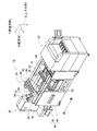
図1に、部品実装機10を示す。部品実装機10は、回路基材12に対する部品の実装作業を実行するための装置である。部品実装機10は、装置本体20、基材搬送保持装置22、部品装着装置24、撮像装置26,28、部品供給装置30、ばら部品供給装置32、制御装置(図12参照)34を備えている。なお、回路基材12として、回路基板、三次元構造の基材等が挙げられ、回路基板として、プリント配線板、プリント回路板等が挙げられる。
<Configuration of component mounting machine>
FIG. 1 shows a component mounting machine 10. The component mounting machine 10 is a device for executing component mounting work on the circuit base material 12. The component mounting machine 10 includes a device main body 20, a base material transfer holding device 22, a component mounting device 24, an image pickup device 26, 28, a component supply device 30, a loose component supply device 32, and a control device (see FIG. 12) 34. There is. Examples of the circuit board 12 include a circuit board, a base material having a three-dimensional structure, and the like, and examples of the circuit board include a printed wiring board and a printed circuit board.

装置本体20は、フレーム部40と、そのフレーム部40に上架されたビーム部42とによって構成されている。基材搬送保持装置22は、フレーム部40の前後方向の中央に配設されており、搬送装置50とクランプ装置52とを有している。搬送装置50は、回路基材12を搬送する装置であり、クランプ装置52は、回路基材12を保持する装置である。これにより、基材搬送保持装置22は、回路基材12を搬送するとともに、所定の位置において、回路基材12を固定的に保持する。なお、以下の説明において、回路基材12の搬送方向をX方向と称し、その方向に直角な水平の方向をY方向と称し、鉛直方向をZ方向と称する。つまり、部品実装機10の幅方向は、X方向であり、前後方向は、Y方向である。 The apparatus main body 20 is composed of a frame portion 40 and a beam portion 42 mounted on the frame portion 40. The base material transfer holding device 22 is arranged at the center of the frame portion 40 in the front-rear direction, and has a transfer device 50 and a clamp device 52. The transport device 50 is a device that transports the circuit base material 12, and the clamp device 52 is a device that holds the circuit base material 12. As a result, the base material transport / holding device 22 transports the circuit base material 12 and holds the circuit base material 12 fixedly at a predetermined position. In the following description, the transport direction of the circuit base material 12 is referred to as the X direction, the horizontal direction perpendicular to that direction is referred to as the Y direction, and the vertical direction is referred to as the Z direction. That is, the width direction of the component mounting machine 10 is the X direction, and the front-rear direction is the Y direction.

部品装着装置24は、ビーム部42に配設されており、2台の作業ヘッド60,62と作業ヘッド移動装置64とを有している。各作業ヘッド60,62は、吸着ノズル(図2参照)66を有しており、吸着ノズル66によって部品を保持する。また、作業ヘッド移動装置64は、X方向移動装置68とY方向移動装置70とZ方向移動装置72とを有している。そして、X方向移動装置68とY方向移動装置70とによって、2台の作業ヘッド60,62は、一体的にフレーム部40上の任意の位置に移動させられる。また、各作業ヘッド60,62は、図2に示すように、スライダ74,76に着脱可能に装着されており、Z方向移動装置72は、スライダ74,76を個別に上下方向に移動させる。つまり、作業ヘッド60,62は、Z方向移動装置72によって、個別に上下方向に移動させられる。 The component mounting device 24 is arranged in the beam unit 42, and has two work heads 60 and 62 and a work head moving device 64. Each work head 60, 62 has a suction nozzle (see FIG. 2) 66, and the parts are held by the suction nozzle 66. Further, the work head moving device 64 has an X direction moving device 68, a Y direction moving device 70, and a Z direction moving device 72. Then, the two work heads 60 and 62 are integrally moved to an arbitrary position on the frame portion 40 by the X-direction moving device 68 and the Y-direction moving device 70. Further, as shown in FIG. 2, the work heads 60 and 62 are detachably attached to the sliders 74 and 76, and the Z-direction moving device 72 individually moves the sliders 74 and 76 in the vertical direction. That is, the work heads 60 and 62 are individually moved in the vertical direction by the Z-direction moving device 72.

撮像装置26は、下方を向いた状態でスライダ74に取り付けられており、作業ヘッド60とともに、X方向,Y方向およびZ方向に移動させられる。これにより、撮像装置26は、フレーム部40上の任意の位置を撮像する。撮像装置28は、図1に示すように、フレーム部40上の基材搬送保持装置22と部品供給装置30との間に、上を向いた状態で配設されている。これにより、撮像装置28は、作業ヘッド60,62の吸着ノズル66に保持された部品を撮像する。 The image pickup apparatus 26 is attached to the slider 74 in a downward facing state, and is moved together with the work head 60 in the X direction, the Y direction, and the Z direction. As a result, the image pickup apparatus 26 images an arbitrary position on the frame portion 40. As shown in FIG. 1, the image pickup apparatus 28 is arranged between the substrate transport holding apparatus 22 on the frame portion 40 and the component supply apparatus 30 in a state of facing upward. As a result, the image pickup apparatus 28 images the parts held by the suction nozzles 66 of the work heads 60 and 62.

部品供給装置30は、フレーム部40の前後方向での一方側の端部に配設されている。部品供給装置30は、トレイ型部品供給装置78とフィーダ型部品供給装置(図示省略)とを有している。トレイ型部品供給装置78は、トレイ上に載置された状態の部品を供給する装置である。フィーダ型部品供給装置は、テープフィーダ(図示省略)、スティックフィーダ(図示省略)によって部品を供給する装置である。 The component supply device 30 is arranged at one end of the frame portion 40 in the front-rear direction. The parts supply device 30 includes a tray-type parts supply device 78 and a feeder-type parts supply device (not shown). The tray-type component supply device 78 is a device that supplies components in a state of being placed on the tray. The feeder type parts supply device is a device that supplies parts by a tape feeder (not shown) and a stick feeder (not shown).

ばら部品供給装置32は、フレーム部40の前後方向での他方側の端部に配設されている。ばら部品供給装置32は、ばらばらに散在された状態の複数の部品を整列させて、整列させた状態で部品を供給する装置である。つまり、任意の姿勢の複数の部品を、所定の姿勢に整列させて、所定の姿勢の部品を供給する装置である。以下に、部品供給装置32の構成について詳しく説明する。なお、部品供給装置30および、ばら部品供給装置32によって供給される部品として、電子回路部品,太陽電池の構成部品,パワーモジュールの構成部品等が挙げられる。また、電子回路部品には、リードを有する部品,リードを有さない部品等が有る。 The loose component supply device 32 is arranged at the other end of the frame portion 40 in the front-rear direction. The loose parts supply device 32 is a device that aligns a plurality of parts that are scattered apart and supplies the parts in the aligned state. That is, it is a device that aligns a plurality of parts in an arbitrary posture in a predetermined posture and supplies the parts in the predetermined posture. The configuration of the component supply device 32 will be described in detail below. Examples of the parts supplied by the parts supply device 30 and the loose parts supply device 32 include electronic circuit parts, solar cell components, power module components, and the like. In addition, electronic circuit parts include parts having leads, parts having no leads, and the like.

ばら部品供給装置32は、図3に示すように、本体80と、部品供給ユニット82と、撮像装置84と、部品引渡し装置86とを有している。 As shown in FIG. 3, the loose parts supply device 32 includes a main body 80, a parts supply unit 82, an image pickup device 84, and a parts delivery device 86.

(a)部品供給ユニット
部品供給ユニット82は、部品供給器88と部品散在装置(図4参照)90と部品戻し装置(図5参照)92とを含み、それら部品供給器88と部品散在装置90と部品戻し装置92とが一体的に構成されたものである。部品供給ユニット82は、本体80のベース96に着脱可能に組み付けられており、ばら部品供給装置32では、5台の部品供給ユニット82が、X方向に1列に並んで配設されている。
(A) Parts supply unit The parts supply unit 82 includes a parts supply device 88, a parts scattering device (see FIG. 4) 90, and a parts returning device (see FIG. 5) 92, and the parts supply device 88 and the parts scattering device 90. And the component return device 92 are integrally configured. The parts supply unit 82 is detachably assembled to the base 96 of the main body 80, and in the loose parts supply device 32, five parts supply units 82 are arranged in a row in the X direction.

(i)部品供給器
部品供給器88は、概して直方体の箱形状をなし、図4及び図5に示すように、Y方向に延びるように配設されている。なお、Y方向を部品供給器88の前後方向と記載し、図5での左方向を前方と、図5での右方向を後方と記載する場合がある。つまり、部品供給ユニット82において、部品戻し装置92が配設されている側に向かう方向を、前方と記載し、部品供給器88が配設されている側に向かう方向を、後方と記載する場合がある。
(I) Parts feeder The parts feeder 88 generally has a rectangular parallelepiped box shape, and is arranged so as to extend in the Y direction as shown in FIGS. 4 and 5. The Y direction may be described as the front-rear direction of the component feeder 88, the left direction in FIG. 5 may be described as the front, and the right direction in FIG. 5 may be described as the rear. That is, in the parts supply unit 82, the direction toward the side where the parts return device 92 is arranged is described as the front, and the direction toward the side where the parts supply device 88 is arranged is described as the rear. There is.

部品供給器88は、上面と前面とにおいて開口しており、上面の開口は、部品の投入口97とされ、前面の開口は部品の排出口98とされている。部品供給器88では、投入口97の下方に、傾斜板104が配設されている。傾斜板104は、部品供給器88の後方側の端面から中央方向に向かって、部品供給器88の幅方向(X方向)の全体に配設されており、前方側の端部が下方に位置するように傾斜している。 The component feeder 88 has openings on the upper surface and the front surface, the opening on the upper surface is a component input port 97, and the opening on the front surface is a component discharge port 98. In the parts feeder 88, the inclined plate 104 is arranged below the input port 97. The inclined plate 104 is arranged in the entire width direction (X direction) of the component feeder 88 from the rear end surface of the component feeder 88 toward the center, and the front end is positioned downward. It is tilted to do.

また、傾斜板104の前方側には、図5に示すように、コンベア装置106が配設されている。コンベア装置106は、1対のローラ108,110とコンベアベルト112とを有している。1対のローラ108,110の各々は、部品供給器88の内部において、部品供給器88の幅方向に延びるように配設されており、部品供給器88の幅方向の全体に架け渡されている。また、ローラ108は、傾斜板104の前方側の端部、つまり、傾斜板104の最も下方に位置する端部とクリアランスのある状態で対向している。なお、傾斜板104の前方側の端部とローラ108とのクリアランスは、部品供給器88によって供給される部品より小さくされている。また、ローラ110は、ローラ108の前方側の斜め上方に配設されている。そして、コンベアベルト112が、1対のローラ108,110に巻き掛けられている。なお、コンベアベルト112は、幅広とされており、コンベアベルト112の幅方向の寸法は、部品供給器88の幅方向の内寸より僅かに小さくされている。 Further, as shown in FIG. 5, a conveyor device 106 is arranged on the front side of the inclined plate 104. The conveyor device 106 has a pair of rollers 108, 110 and a conveyor belt 112. Each of the pair of rollers 108 and 110 is arranged inside the component feeder 88 so as to extend in the width direction of the component feeder 88, and is spread over the entire width direction of the component feeder 88. There is. Further, the roller 108 faces the front end of the inclined plate 104, that is, the lowermost end of the inclined plate 104 with a clearance. The clearance between the front end of the inclined plate 104 and the roller 108 is smaller than that of the parts supplied by the parts feeder 88. Further, the roller 110 is arranged diagonally upward on the front side of the roller 108. Then, the conveyor belt 112 is wound around a pair of rollers 108 and 110. The conveyor belt 112 is wide, and the width direction of the conveyor belt 112 is slightly smaller than the inner dimension of the component feeder 88 in the width direction.

また、1対のローラ108,110は軸心周りに回転可能とされており、回転装置114の作動により制御可能に回転する。なお、各ローラ108,110の回転方向は、図5での反時計回りの方向とされている。これにより、コンベアベルト112が、1対のローラ108,110の間において、図5での反時計回りに回転する。つまり、コンベアベルト112による搬送方向は、傾斜板104の前端部から前方に向かって斜め上方とされている。なお、コンベアベルト112の表面、つまり、搬送面には、コンベアベルト112の幅方向に延びるように、複数の突起部115が形成されている。複数の突起部115は、コンベアベルト112の回転方向において一定の間隔で形成されており、その間隔は、部品供給器88によって供給される部品の長さ方向の寸法より長くされている。 Further, the pair of rollers 108 and 110 are rotatable around the axis, and rotate in a controllable manner by the operation of the rotating device 114. The rotation directions of the rollers 108 and 110 are counterclockwise in FIG. As a result, the conveyor belt 112 rotates counterclockwise in FIG. 5 between the pair of rollers 108 and 110. That is, the transport direction by the conveyor belt 112 is obliquely upward from the front end portion of the inclined plate 104 toward the front. A plurality of protrusions 115 are formed on the surface of the conveyor belt 112, that is, on the transport surface so as to extend in the width direction of the conveyor belt 112. The plurality of protrusions 115 are formed at regular intervals in the rotation direction of the conveyor belt 112, and the intervals are longer than the dimension in the length direction of the parts supplied by the parts feeder 88.

また、コンベア装置106のローラ110の前方側の斜め上方には、ブラシ保持部123が配設されている。ブラシ保持部123は、部品供給器88の幅方向に延びるように配設されており、部品供給器88の幅方向の全体に架け渡されている。そして、そのブラシ保持部123の下端部には、コンベア装置106のローラ110に向かって延び出すように、幅広のブラシ124が取り付けられている。なお、ブラシ124の幅方向の寸法は、部品供給器88の幅方向の内寸より僅かに小さくされており、ローラ110に巻き掛けられているコンベアベルト112と、部品供給器88の幅方向の全体に渡って、クリアランスのある状態で対向している。なお、ブラシ124の先端と、ローラ110に巻き掛けられているコンベアベルト112とのクリアランスは、部品供給器88によって供給される部品の厚さ方向の寸法より長く、厚さ方向の寸法の2倍未満とされている。 Further, a brush holding portion 123 is arranged diagonally above the front side of the roller 110 of the conveyor device 106. The brush holding portion 123 is arranged so as to extend in the width direction of the component feeder 88, and extends over the entire width direction of the component feeder 88. A wide brush 124 is attached to the lower end of the brush holding portion 123 so as to extend toward the roller 110 of the conveyor device 106. The width direction of the brush 124 is slightly smaller than the inner dimension of the parts feeder 88 in the width direction, and the conveyor belt 112 wound around the roller 110 and the parts feeder 88 in the width direction They face each other with clearance throughout. The clearance between the tip of the brush 124 and the conveyor belt 112 wound around the roller 110 is longer than the dimension in the thickness direction of the parts supplied by the component feeder 88 and twice the dimension in the thickness direction. It is said to be less than.

また、コンベア装置106のローラ110の前方側の斜め下方には、傾斜板126が配設されている。傾斜板126は、部品供給器88の前方側の端面からローラ110の下方に向かって、部品供給器88の幅方向の全体に配設されており、後方側の端部が下方に位置するように傾斜している。さらに、その傾斜板126の下方にも、傾斜板128が配設されている。傾斜板128は、コンベア装置106の中央部の下方から部品供給器88の排出口98に向かって、部品供給器88の幅方向の全体に配設されており、前方側の端部が下方に位置するように傾斜している。なお、傾斜板128の後方側の端部は、傾斜板126の後方側の端部より後方に位置しており、その傾斜板128の後方側の端部は、上方に向かって直角に屈曲されている。また、傾斜板128の前方側の端部は、概して水平となるように後方に向かって屈曲されている。 Further, an inclined plate 126 is arranged diagonally downward on the front side of the roller 110 of the conveyor device 106. The inclined plate 126 is arranged in the entire width direction of the component feeder 88 from the front end surface of the component feeder 88 toward the lower side of the roller 110 so that the rear end is located downward. It is inclined to. Further, the inclined plate 128 is also arranged below the inclined plate 126. The inclined plate 128 is arranged in the entire width direction of the component feeder 88 from below the central portion of the conveyor device 106 toward the discharge port 98 of the component feeder 88, and the front end is downward. It is tilted to be located. The rear end of the inclined plate 128 is located behind the rear end of the inclined plate 126, and the rear end of the inclined plate 128 is bent at a right angle upward. ing. Further, the front end portion of the inclined plate 128 is bent rearward so as to be generally horizontal.

なお、ベース96には、図4に示すように、1対のサイドフレーム部130が組み付けられている。1対のサイドフレーム部130は、対向した状態で互いに平行且つ、Y方向に延びるように立設されている。そして、1対のサイドフレーム部130の間の距離は、部品供給器88の幅方向の寸法より僅かに大きくされており、1対のサイドフレーム部130の間に、部品供給器88が着脱可能に装着されている。 As shown in FIG. 4, a pair of side frame portions 130 are assembled to the base 96. The pair of side frame portions 130 are erected so as to be parallel to each other and extend in the Y direction while facing each other. The distance between the pair of side frame portions 130 is slightly larger than the widthwise dimension of the component feeder 88, and the component feeder 88 can be attached and detached between the pair of side frame portions 130. It is attached to.

(ii)部品散在装置
部品散在装置90は、部品支持部材150と部品支持部材移動装置152とを含む。部品支持部材150は、ステージ156と1対の側壁部158とによって構成されている。ステージ156は、概して長手形状の板形状をなし、1対のサイドフレーム部130の間に装着された部品供給器88の下方から前方に延び出すように、配設されている。なお、ステージ156の上面は、概して水平とされており、図5に示すように、部品供給器88の傾斜板128の屈曲された前方側の端部と僅かなクリアランスのある状態で配設されている。また、1対の側壁部158は、図4に示すように、ステージ156の長手方向の両側部に立設された状態で固定されており、各側壁部158の上端は、ステージ156の上面より上方に延び出している。
(Ii) Parts Scattering Device The parts scattering device 90 includes a component support member 150 and a component support member moving device 152. The component support member 150 is composed of a stage 156 and a pair of side wall portions 158. The stage 156 has a generally elongated plate shape, and is arranged so as to extend from the lower side to the front side of the component feeder 88 mounted between the pair of side frame portions 130. The upper surface of the stage 156 is generally horizontal, and is arranged with a slight clearance from the bent front end of the inclined plate 128 of the component feeder 88, as shown in FIG. ing. Further, as shown in FIG. 4, the pair of side wall portions 158 are fixed in a state of being erected on both side portions in the longitudinal direction of the stage 156, and the upper end of each side wall portion 158 is from the upper surface of the stage 156. It extends upward.

また、部品支持部材移動装置152は、図5に示すように、ガイドレール160とスライダ162とを含む。ガイドレール160は、部品支持部材150の下方において、ステージ156の長手方向に延びるように配設されている。スライダ162は、ガイドレール160にスライド可能に取り付けられており、電磁モータ(図12参照)166の作動により、任意の位置にスライドする。また、部品支持部材150のステージ156は、連結機構168を介してスライダ162に連結されている。これにより、部品支持部材150は、部品支持部材移動装置152の作動によりY方向に移動し、部品供給器88の下方に格納された格納状態(図6参照)と、部品供給器88の下方から露出した露出状態(図5参照)との間で移動する。 Further, the component support member moving device 152 includes a guide rail 160 and a slider 162 as shown in FIG. The guide rail 160 is arranged below the component support member 150 so as to extend in the longitudinal direction of the stage 156. The slider 162 is slidably attached to the guide rail 160 and slides to an arbitrary position by the operation of the electromagnetic motor (see FIG. 12) 166. Further, the stage 156 of the component support member 150 is connected to the slider 162 via the connecting mechanism 168. As a result, the component support member 150 moves in the Y direction by the operation of the component support member moving device 152, and is stored in the stored state below the component feeder 88 (see FIG. 6) and from below the component feeder 88. Move to and from the exposed exposed state (see FIG. 5).

(iii)部品戻し装置
部品戻し装置92は、図7に示すように、部品回収容器180と容器搖動装置181とを含む。部品回収容器180は、概して箱状をなし、底面が円弧形状とされている。部品回収容器180は、部品支持部材150のステージ156の前方側の端部において搖動可能に保持されており、容器搖動装置181の作動により、揺動する。この際、部品回収容器180は、開口を上方に向けた回収姿勢(図7参照)と、開口を部品支持部材150のステージ156の上面に向けた戻し姿勢(図8参照)との間で搖動する。
(Iii) Parts Returning Device The parts returning device 92 includes a parts collecting container 180 and a container swinging device 181 as shown in FIG. 7. The parts collection container 180 is generally box-shaped and has an arcuate bottom surface. The component collection container 180 is oscillatedly held at the front end of the stage 156 of the component support member 150, and swings by the operation of the container oscillating device 181. At this time, the parts collection container 180 swings between a collection posture with the opening facing upward (see FIG. 7) and a return posture with the opening facing the upper surface of the stage 156 of the parts support member 150 (see FIG. 8). To do.

(b)撮像装置
撮像装置84は、図3に示すように、カメラ290とカメラ移動装置292とを含む。カメラ移動装置292は、ガイドレール296とスライダ298とを含む。ガイドレール296は、部品供給器88の上方において、ばら部品供給装置32の幅方向(X方向)に延びるように、本体80に固定されている。スライダ298は、ガイドレール296にスライド可能に取り付けられており、電磁モータ(図12参照)299の作動により、任意の位置にスライドする。また、カメラ290は、下方を向いた状態でスライダ298に装着されている。
(B) Imaging device The imaging device 84 includes a camera 290 and a camera moving device 292, as shown in FIG. The camera moving device 292 includes a guide rail 296 and a slider 298. The guide rail 296 is fixed to the main body 80 so as to extend in the width direction (X direction) of the loose component supply device 32 above the component supply device 88. The slider 298 is slidably attached to the guide rail 296 and slides to an arbitrary position by the operation of the electromagnetic motor (see FIG. 12) 299. Further, the camera 290 is attached to the slider 298 in a state of facing downward.

(c)部品引渡し装置
部品引渡し装置86は、図3に示すように、部品保持ヘッド移動装置300と部品保持ヘッド302と2台のシャトル装置304とを含む。
(C) Parts delivery device As shown in FIG. 3, the parts delivery device 86 includes a parts holding head moving device 300, a parts holding head 302, and two shuttle devices 304.

部品保持ヘッド移動装置300は、X方向移動装置310とY方向移動装置312とZ方向移動装置314とを含む。Y方向移動装置312は、X方向に延びるように、部品供給ユニット82の上方に配設されたYスライダ316を有しており、Yスライダ316は、電磁モータ(図12参照)319の駆動により、Y方向の任意の位置に移動する。X方向移動装置310は、Yスライダ316の側面に配設されたXスライダ320を有しており、Xスライダ320は、電磁モータ(図12参照)321の駆動により、X方向の任意の位置に移動する。Z方向移動装置314は、Xスライダ320の側面に配設されたZスライダ322を有しており、Zスライダ322は、電磁モータ(図12参照)323の駆動により、Z方向の任意の位置に移動する。 The component holding head moving device 300 includes an X-direction moving device 310, a Y-direction moving device 312, and a Z-direction moving device 314. The Y-direction moving device 312 has a Y slider 316 arranged above the component supply unit 82 so as to extend in the X direction, and the Y slider 316 is driven by an electromagnetic motor (see FIG. 12) 319. , Move to any position in the Y direction. The X-direction moving device 310 has an X-slider 320 arranged on the side surface of the Y-slider 316, and the X-slider 320 is moved to an arbitrary position in the X-direction by driving an electromagnetic motor (see FIG. 12) 321. Moving. The Z direction moving device 314 has a Z slider 322 arranged on the side surface of the X slider 320, and the Z slider 322 is moved to an arbitrary position in the Z direction by driving an electromagnetic motor (see FIG. 12) 323. Moving.

部品保持ヘッド302は、図9に示すように、ヘッド本体330とチャック332と旋回装置334と回転装置335とを含む。ヘッド本体330は、Zスライダ322と一体的に形成されている。チャック332は、図10に示すように、本体部337と1対の爪部338とを含む。1対の爪部338は、本体部337の下面から下方に延び出すように配設されており、互いに接近・離間可能にスライドする。これにより、チャック332は、1対の爪部338を接近させることで、1対の爪部338によって部品を狭持し、1対の爪部338を離間させることで、1対の爪部338の間から部品を離脱する。なお、チャック332は、図9に示すように、ホルダ340の下端部に着脱可能に装着される。 As shown in FIG. 9, the component holding head 302 includes a head main body 330, a chuck 332, a swivel device 334, and a rotary device 335. The head body 330 is integrally formed with the Z slider 322. As shown in FIG. 10, the chuck 332 includes a main body portion 337 and a pair of claw portions 338. The pair of claw portions 338 are arranged so as to extend downward from the lower surface of the main body portion 337, and slide so as to be close to and separated from each other. As a result, the chuck 332 holds the parts by the pair of claws 338 by bringing the pair of claws 338 closer to each other, and separates the pair of claws 338 from each other to separate the pair of claws 338. Remove the part from between. As shown in FIG. 9, the chuck 332 is detachably attached to the lower end portion of the holder 340.

ホルダ340は、支持軸344において屈曲可能とされており、旋回装置334の作動により、ホルダ340が上方向に90度屈曲する。これにより、ホルダ340の下端部に装着されているチャック332は、90度旋回し、旋回位置に位置する。つまり、チャック332は、旋回装置334の作動により、非旋回位置と旋回位置との間で旋回する。また、回転装置335は、チャック332を軸心周りに回転させる。 The holder 340 is bendable on the support shaft 344, and the holder 340 is bent 90 degrees upward by the operation of the swivel device 334. As a result, the chuck 332 mounted on the lower end of the holder 340 turns 90 degrees and is positioned at the turning position. That is, the chuck 332 is swiveled between the non-swivel position and the swivel position by the operation of the swivel device 334. Further, the rotating device 335 rotates the chuck 332 around the axis.

また、2台のシャトル装置304の各々は、図3に示すように、部品キャリヤ388と部品キャリヤ移動装置390とを含み、部品供給ユニット82の前方側に横方向に並んで、本体80に固定されている。部品キャリヤ388には、5個の部品受け部材392が、横方向に一列に並んだ状態で装着されており、各部品受け部材392に、部品が載置される。 Further, as shown in FIG. 3, each of the two shuttle devices 304 includes the component carrier 388 and the component carrier moving device 390, is arranged laterally on the front side of the component supply unit 82, and is fixed to the main body 80. Has been done. Five component receiving members 392 are mounted on the component carrier 388 in a line in the horizontal direction, and the components are placed on the component receiving members 392.

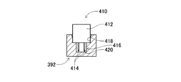
詳しくは、ばら部品供給装置32で供給される部品は、図11に示すように、リードを有する電子回路部品(以下、「リード部品」と略す場合がある)410であり、リード部品410は、直方体形状の部品本体412と、部品本体412の底面から突出する2本のリード414とから構成されている。また、部品受け部材392には、部品受容凹部416が形成されている。部品受容凹部416は、段付き形状の凹部であり、部品受け部材392の上面に開口する本体部受容凹部418と、その本体部受容凹部418の底面に開口するリード受容凹部420とから構成されている。そして、リード部品410は、リード414が下方を向く姿勢で、部品受容凹部416の内部に挿入される。これにより、リード414がリード受容凹部420に挿入されるとともに、部品本体412が本体部受容凹部418に挿入された状態で、リード部品410が部品受容凹部416の内部に載置される。 Specifically, as shown in FIG. 11, the component supplied by the loose component supply device 32 is an electronic circuit component having a lead (hereinafter, may be abbreviated as “lead component”) 410, and the lead component 410 is a lead component 410. It is composed of a rectangular parallelepiped component body 412 and two leads 414 protruding from the bottom surface of the component body 412. Further, the component receiving recess 416 is formed in the component receiving member 392. The component receiving recess 416 is a recess having a stepped shape, and is composed of a main body receiving recess 418 opening on the upper surface of the component receiving member 392 and a lead receiving recess 420 opening on the bottom surface of the main body receiving recess 418. There is. Then, the lead component 410 is inserted into the component receiving recess 416 with the lead 414 facing downward. As a result, the lead component 410 is placed inside the component receiving recess 416 in a state where the lead 414 is inserted into the lead receiving recess 420 and the component main body 412 is inserted into the main body receiving recess 418.

また、部品キャリヤ移動装置390は、図3に示すように、板状の長手部材であり、前後方向に延びるように、部品供給ユニット82の前方側に配設されている。部品キャリヤ移動装置390の上面には、部品キャリヤ388が前後方向にスライド可能に配設されており、電磁モータ(図12参照)430の駆動により、前後方向の任意の位置にスライドする。なお、部品キャリヤ388が、部品供給ユニット82に接近する方向にスライドした際には、部品保持ヘッド移動装置300による部品保持ヘッド302の移動範囲内に位置する部品受取位置までスライドする。一方、部品キャリヤ388が、部品供給ユニット82から離れる方向にスライドした際には、作業ヘッド移動装置64による作業ヘッド60,62の移動範囲内に位置する部品供給位置までスライドする。 Further, as shown in FIG. 3, the component carrier moving device 390 is a plate-shaped longitudinal member, and is arranged on the front side of the component supply unit 82 so as to extend in the front-rear direction. A component carrier 388 is slidably arranged on the upper surface of the component carrier moving device 390 in the front-rear direction, and is slid to an arbitrary position in the front-rear direction by driving an electromagnetic motor (see FIG. 12) 430. When the component carrier 388 slides in the direction approaching the component supply unit 82, it slides to the component receiving position located within the moving range of the component holding head 302 by the component holding head moving device 300. On the other hand, when the component carrier 388 slides away from the component supply unit 82, it slides to the component supply position located within the movement range of the work heads 60 and 62 by the work head moving device 64.

また、制御装置34は、図12に示すように、統括制御装置450と、複数の個別制御装置(図では1つのみ図示されている)452と、画像処理装置454と、記憶装置456とを含む。統括制御装置450は、コンピュータを主体として構成されたものであり、基材搬送保持装置22,部品装着装置24,撮像装置26,撮像装置28,部品供給装置30,ばら部品供給装置32に接続されている。これにより、統括制御装置450は、基材搬送保持装置22,部品装着装置24,撮像装置26,撮像装置28,部品供給装置30,ばら部品供給装置32を統括して制御する。複数の個別制御装置452は、コンピュータを主体として構成されたものであり、基材搬送保持装置22,部品装着装置24,撮像装置26,撮像装置28,部品供給装置30,ばら部品供給装置32に対応して設けられている(図では、ばら部品供給装置32に対応する個別制御装置452のみが図示されている)。ばら部品供給装置32の個別制御装置452は、部品散在装置90,部品戻し装置92,カメラ移動装置292,部品保持ヘッド移動装置300,部品保持ヘッド302,シャトル装置304に接続されている。これにより、ばら部品供給装置32の個別制御装置452は、部品散在装置90,部品戻し装置92,カメラ移動装置292,部品保持ヘッド移動装置300,部品保持ヘッド302,シャトル装置304を制御する。また、画像処理装置454は、撮像装置84に接続されており、撮像装置84により撮像された撮像データを処理する。その画像処理装置454は、ばら部品供給装置32の個別制御装置452に接続されている。これにより、ばら部品供給装置32の個別制御装置452は、撮像装置84により撮像された撮像データを取得する。また、記憶装置456は、各種データを記憶しており、個別制御装置452に接続されている。これにより、個別制御装置452は、記憶装置456から各種データを取得する。 Further, as shown in FIG. 12, the control device 34 includes a central control device 450, a plurality of individual control devices (only one is shown in the figure) 452, an image processing device 454, and a storage device 456. Including. The integrated control device 450 is mainly composed of a computer, and is connected to a base material transport holding device 22, a component mounting device 24, an image pickup device 26, an image pickup device 28, a component supply device 30, and a loose component supply device 32. ing. As a result, the integrated control device 450 collectively controls the base material transfer holding device 22, the component mounting device 24, the image pickup device 26, the image pickup device 28, the component supply device 30, and the loose component supply device 32. The plurality of individual control devices 452 are mainly composed of a computer, and are included in the base material transport holding device 22, the component mounting device 24, the imaging device 26, the imaging device 28, the component supply device 30, and the loose component supply device 32. Correspondingly provided (in the figure, only the individual control device 452 corresponding to the loose component supply device 32 is shown). The individual control device 452 of the loose parts supply device 32 is connected to the parts scattering device 90, the parts returning device 92, the camera moving device 292, the parts holding head moving device 300, the parts holding head 302, and the shuttle device 304. As a result, the individual control device 452 of the loose parts supply device 32 controls the parts scattering device 90, the parts returning device 92, the camera moving device 292, the parts holding head moving device 300, the parts holding head 302, and the shuttle device 304. Further, the image processing device 454 is connected to the image pickup device 84 and processes the image pickup data captured by the image pickup device 84. The image processing device 454 is connected to the individual control device 452 of the loose component supply device 32. As a result, the individual control device 452 of the loose component supply device 32 acquires the image pickup data captured by the image pickup device 84. Further, the storage device 456 stores various data and is connected to the individual control device 452. As a result, the individual control device 452 acquires various data from the storage device 456.

<部品実装機の作動>
部品実装機10は、上述した構成によって、基材搬送保持装置22に保持された回路基材12に対して部品の装着作業が行われる。具体的には、回路基材12が、作業位置まで搬送され、その位置において、クランプ装置52によって固定的に保持される。次に、撮像装置26が、回路基材12の上方に移動し、回路基材12を撮像する。これにより、回路基材12の保持位置の誤差に関する情報が得られる。また、部品供給装置30若しくは、ばら部品供給装置32は、所定の供給位置において、部品を供給する。なお、ばら部品供給装置32による部品の供給に関しては、後で詳しく説明する。そして、作業ヘッド60,62の何れかが、部品の供給位置の上方に移動し、吸着ノズル66によって部品を保持する。続いて、部品を保持した作業ヘッド60,62が、撮像装置28の上方に移動し、撮像装置28によって、吸着ノズル66に保持された部品が撮像される。これにより、部品の保持位置の誤差に関する情報が得られる。そして、部品を保持した作業ヘッド60,62が、回路基材12の上方に移動し、保持している部品を、回路基材12の保持位置の誤差,部品の保持位置の誤差等を補正し、回路基材12上に装着する。
<Operation of component mounting machine>
With the above-described configuration, the component mounting machine 10 performs component mounting work on the circuit base material 12 held by the base material transfer holding device 22. Specifically, the circuit base material 12 is conveyed to a working position, and is fixedly held by the clamp device 52 at that position. Next, the image pickup apparatus 26 moves above the circuit base material 12 and images the circuit base material 12. As a result, information regarding an error in the holding position of the circuit base material 12 can be obtained. Further, the parts supply device 30 or the loose parts supply device 32 supplies parts at a predetermined supply position. The supply of parts by the loose parts supply device 32 will be described in detail later. Then, one of the work heads 60 and 62 moves above the supply position of the component and holds the component by the suction nozzle 66. Subsequently, the work heads 60 and 62 holding the parts move above the image pickup device 28, and the image pickup device 28 images the parts held by the suction nozzle 66. This provides information about the error in the holding position of the component. Then, the work heads 60 and 62 holding the parts move above the circuit base material 12, and the parts being held are corrected for an error in the holding position of the circuit base material 12, an error in the holding position of the parts, and the like. , Mounted on the circuit substrate 12.

<ばら部品供給装置の作動>
(a)ばら部品供給装置によるリード部品の供給
ばら部品供給装置32では、リード部品410が、作業者によって部品供給器88の投入口97から投入され、その投入されたリード部品410が、部品供給ユニット82,部品引渡し装置86の作動により、部品キャリヤ388の部品受け部材392に載置された状態で供給される。詳しくは、作業者は、部品供給器88の上面の投入口97から、リード部品410を投入する。この際、部品支持部材150は、部品支持部材移動装置152の作動により、部品供給器88の下方に移動しており、格納状態とされる(図6参照)。なお、部品支持部材150が格納状態とされている際に、部品支持部材150の前方側の端部に配設された部品回収容器180は、部品供給器88の前方に位置しており、部品回収容器180の開口を上方に向けた姿勢(回収姿勢:図7参照)とされている。
<Operation of loose parts supply device>
(A) Supply of lead parts by the loose parts supply device In the loose parts supply device 32, the lead parts 410 are input by an operator from the input port 97 of the parts feeder 88, and the inserted lead parts 410 are supplied with parts. By operating the unit 82 and the component delivery device 86, the unit 82 is supplied while being mounted on the component receiving member 392 of the component carrier 388. Specifically, the operator inputs the lead component 410 from the input port 97 on the upper surface of the component feeder 88. At this time, the component support member 150 is moved below the component feeder 88 by the operation of the component support member moving device 152, and is brought into the retracted state (see FIG. 6). When the component support member 150 is in the retracted state, the component collection container 180 arranged at the front end of the component support member 150 is located in front of the component feeder 88 and is a component. The posture is such that the opening of the collection container 180 is directed upward (collection posture: see FIG. 7).

部品供給器88の投入口97から投入されたリード部品410は、部品供給器88の傾斜板104の上に落下し、傾斜板104の前方側の下端まで転がり落ちる。この際、傾斜板104の前方側の下端まで転がり落ちたリード部品410は、傾斜板104の前方側の下端と、コンベア装置106の後方側の下端との間に山積される。つまり、傾斜板104の前方側の下端と、コンベア装置106の後方側の下端との間が、リード部品410を収容するための収容部100として機能している。そして、コンベア装置106の回転装置114が作動されることで、コンベア装置106のコンベアベルト112が図6での反時計回りに周回する。これにより、収容部100に山積されたリード部品410が、コンベアベルト112によって前方側の斜め上方に向かって搬送される。 The lead component 410 inserted from the input port 97 of the component feeder 88 falls on the inclined plate 104 of the component feeder 88 and rolls down to the lower end on the front side of the inclined plate 104. At this time, the lead component 410 that has rolled down to the lower end on the front side of the inclined plate 104 is piled up between the lower end on the front side of the inclined plate 104 and the lower end on the rear side of the conveyor device 106. That is, the space between the lower end on the front side of the inclined plate 104 and the lower end on the rear side of the conveyor device 106 functions as an accommodating portion 100 for accommodating the lead component 410. Then, when the rotating device 114 of the conveyor device 106 is operated, the conveyor belt 112 of the conveyor device 106 orbits counterclockwise in FIG. As a result, the lead parts 410 piled up in the accommodating portion 100 are conveyed diagonally upward on the front side by the conveyor belt 112.

そして、コンベアベルト112によって斜め上方に向かって搬送されたリード部品410は、コンベア装置106の前方側の上端とブラシ124との間を通過し、コンベア装置106の前方側の上端とブラシ124との下方に配設された傾斜板126の上に落下する。その傾斜板126の上に落下したリード部品410は、傾斜板126の上を後方に向かって転がり落ち、傾斜板126の下方に配設された傾斜板128に上に落下する。その傾斜板128の上に落下したリード部品410は前方に向かって転がり落ち、部品供給器88の前方側の排出口98から排出される。このように、コンベア装置106の前方側の上端から落下したリード部品410は、一旦、傾斜板126の上に落下し、その後に、傾斜板128に上に落下する。そして、部品供給器88の排出口98からリード部品410が排出される。これにより、リード部品410の落下によるダメージを低減することが可能となる。 Then, the lead component 410 conveyed obliquely upward by the conveyor belt 112 passes between the upper end on the front side of the conveyor device 106 and the brush 124, and the upper end on the front side of the conveyor device 106 and the brush 124. It falls on the inclined plate 126 arranged below. The lead component 410 that has fallen on the inclined plate 126 rolls backward on the inclined plate 126 and falls on the inclined plate 128 arranged below the inclined plate 126. The lead component 410 that has fallen onto the inclined plate 128 rolls forward and is discharged from the discharge port 98 on the front side of the component feeder 88. In this way, the lead component 410 that has fallen from the upper end on the front side of the conveyor device 106 once falls on the inclined plate 126, and then falls on the inclined plate 128. Then, the lead component 410 is discharged from the discharge port 98 of the component feeder 88. This makes it possible to reduce the damage caused by dropping the lead component 410.

また、部品支持部材150は、部品供給器88の排出口98からリード部品410が排出されるタイミングに合わせて、部品支持部材移動装置152の作動により、部品供給器88の下方から前方に向かって移動させられる。これにより、部品供給器88の排出口98から排出されたリード部品410が、部品支持部材150のステージ156の上面に排出される。 Further, the component support member 150 is operated from the lower side to the front side of the component support member 88 by the operation of the component support member moving device 152 at the timing when the lead component 410 is discharged from the discharge port 98 of the component supply device 88. Can be moved. As a result, the lead component 410 discharged from the discharge port 98 of the component feeder 88 is discharged to the upper surface of the stage 156 of the component support member 150.

なお、部品供給器88からステージ156の上に排出されたリード部品410が前方に向かって転がり、ステージ156の前端から転がり落ちた場合には、部品回収容器180に収納される。また、部品供給器88からステージ156の上に排出されたリード部品410が側方に向かって転がった場合には、部品支持部材150の側壁部158によって、ステージ156からのリード部品410の落下が防止される。 When the lead component 410 discharged from the component feeder 88 onto the stage 156 rolls forward and rolls down from the front end of the stage 156, it is stored in the component collection container 180. Further, when the lead component 410 discharged from the component feeder 88 onto the stage 156 rolls sideways, the side wall portion 158 of the component support member 150 causes the lead component 410 to fall from the stage 156. Be prevented.

そして、部品支持部材150が、格納状態から前方に向かって移動させられ、露出状態に至ると、部品支持部材150の移動が停止される。これにより、ステージ156の上面全体にリード部品410が散在される。なお、部品供給器88では、部品支持部材150の移動が停止するタイミングに合わせて、部品供給器88からリード部品410が最後に排出されるように、コンベア装置106の作動が停止される。 Then, the component support member 150 is moved forward from the retracted state, and when the exposed state is reached, the movement of the component support member 150 is stopped. As a result, the lead components 410 are scattered over the entire upper surface of the stage 156. In the component feeder 88, the operation of the conveyor device 106 is stopped so that the lead component 410 is finally discharged from the component feeder 88 at the timing when the movement of the component support member 150 is stopped.

なお、部品供給器88から部品支持部材150のステージ156の上にリード部品410が散在されると、図13に示すように、リード部品410は、概ね3つの姿勢でステージ156の上に散在される。具体的には、リード部品410は、リード414の延び出す面が側方を向き、その2本のリード414が概して水平方向に並んだ状態の姿勢(以下、「第1姿勢」と記載する場合がある)と、リード414の延び出す面が側方を向き、その2本のリード414が概して鉛直方向に並んだ状態の姿勢(以下、「第2姿勢」と記載する場合がある)と、リード414の延び出す面が上方を向いた状態の姿勢(以下、「第3姿勢」と記載する場合がある)との3つの姿勢で、ステージ156の上に散在される。なお、リード部品410を散在される姿勢によって区別する際に、第1姿勢のリード部品410a、第2姿勢のリード部品410b、第1姿勢のリード部品410cと記載する。 When the lead parts 410 are scattered on the stage 156 of the parts support member 150 from the parts feeder 88, the lead parts 410 are scattered on the stage 156 in roughly three postures as shown in FIG. To. Specifically, the lead component 410 is in a posture in which the extending surface of the lead 414 faces sideways and the two leads 414 are generally arranged in the horizontal direction (hereinafter, referred to as "first posture"). The posture in which the extending surface of the lead 414 faces sideways and the two leads 414 are generally arranged in the vertical direction (hereinafter, may be referred to as "second posture"). The leads 414 are scattered on the stage 156 in three postures, that is, a posture in which the extending surface of the lead 414 faces upward (hereinafter, may be referred to as a "third posture"). When the lead parts 410 are distinguished by the scattered postures, they are described as the lead parts 410a in the first posture, the lead parts 410b in the second posture, and the lead parts 410c in the first posture.

リード部品410が、上述したようにステージ156の上に散在されると、撮像装置84のカメラ290が、カメラ移動装置292の作動により、部品支持部材150の上方に移動し、リード部品410を撮像する。そして、カメラ290により撮像された撮像データに基づいて、ピックアップの対象となるリード部品(以下、「ピックアップ対象部品」と略す場合がある)が、パターンマッチングによって特定される。 When the lead component 410 is scattered on the stage 156 as described above, the camera 290 of the image pickup device 84 moves above the component support member 150 by the operation of the camera moving device 292, and images the lead component 410. To do. Then, based on the imaging data captured by the camera 290, the lead component to be picked up (hereinafter, may be abbreviated as “pickup target component”) is specified by pattern matching.

具体的には、カメラ290によるリード部品410の撮像データに基づいて、リード部品410の外形線(アウトライン)が特定され、リード部品410の上面の形状、つまり、リード部品410の上方からの視点における形状が演算される。さらに、撮像データに基づいて、リード部品410の位置も演算される。一方、記憶装置456には、図14に示すように、第1姿勢のリード部品410aの外形線に応じた形状の画像データ(以下、「第1姿勢部品画像データ」と略する場合がある)と、第2姿勢のリード部品410bの外形線に応じた形状の画像データ(以下、「第2姿勢部品画像データ」と略する場合がある)とが記憶されている。 Specifically, the outline of the lead component 410 is specified based on the imaging data of the lead component 410 by the camera 290, and the shape of the upper surface of the lead component 410, that is, the viewpoint from above the lead component 410. The shape is calculated. Further, the position of the lead component 410 is also calculated based on the imaging data. On the other hand, as shown in FIG. 14, the storage device 456 has image data having a shape corresponding to the outline of the lead component 410a in the first posture (hereinafter, may be abbreviated as "first posture component image data"). And the image data of the shape corresponding to the outline of the lead component 410b in the second posture (hereinafter, may be abbreviated as "second posture component image data") are stored.

そして、撮像データに基づいて演算されたリード部品410の上面の形状(以下、「撮像部品形状」と記載する場合がある)が、第1姿勢部品画像データに基づくリード部品410の形状(以下、「第1記憶部品形状」と記載する場合がある)、若しくは、第2姿勢部品画像データに基づくリード部品410の形状(以下、「第2記憶部品形状」と記載する場合がある)と一致するか否かが判断される。そして、撮像部品形状が第1記憶部品形状、若しくは、第2記憶部品形状と一致すると判断された場合に、その撮像部品形状に応じたリード部品410が、ピックアップ対象部品として設定される。つまり、第1姿勢のリード部品410aおよび、第2姿勢のリード部品410bが、ピックアップ対象部品として設定され、第3姿勢のリード部品410cは、ピックアップ対象部品として設定されない。これは、第3姿勢のリード部品410cでは、上面にリード414が配設されており、リード414が邪魔になり、リード部品410をチャック332により適切に保持できないためである。 The shape of the upper surface of the lead component 410 calculated based on the imaged data (hereinafter, may be referred to as “imaged component shape”) is the shape of the lead component 410 based on the first posture component image data (hereinafter, referred to as “imaged component shape”). It may be described as "first storage component shape"), or it matches the shape of the lead component 410 based on the second posture component image data (hereinafter, may be described as "second storage component shape"). Whether or not it is judged. Then, when it is determined that the shape of the image pickup component matches the shape of the first storage component or the shape of the second storage component, the lead component 410 corresponding to the shape of the image pickup component is set as the pickup target component. That is, the lead component 410a in the first posture and the lead component 410b in the second posture are set as the pickup target parts, and the lead component 410c in the third posture is not set as the pickup target component. This is because the lead 414 is arranged on the upper surface of the lead component 410c in the third posture, the lead 414 becomes an obstacle, and the lead component 410 cannot be properly held by the chuck 332.

ただし、第1姿勢のリード部品410aおよび、第2姿勢のリード部品410bであっても、チャック332により適切に保持できない場合がある。具体的に、図13に示すようにリード部品410が散在されている場合について説明する。図13での左側の上方に位置する2個の第1姿勢のリード部品410aの隙間は、ある程度、大きい。このため、それら2個のリード部品410aのうちの一方のリード部品410aをチャック332によりピックアップする際に、チャック332が他方のリード部品410aに干渉しないと想定されるため、適切なピックアップが担保される。一方、図13での右側に位置する2個の第1姿勢のリード部品410aの隙間は、比較的小さい。このため、それら2個のリード部品410aのうちの一方のリード部品410aをチャック332によりピックアップする際に、チャック332が他方のリード部品410aに干渉する虞があり、適切なピックアップを担保することができない。 However, even the lead component 410a in the first posture and the lead component 410b in the second posture may not be properly held by the chuck 332. Specifically, a case where lead parts 410 are scattered as shown in FIG. 13 will be described. The gap between the two lead parts 410a in the first posture located above the left side in FIG. 13 is large to some extent. Therefore, when one of the two lead parts 410a is picked up by the chuck 332, it is assumed that the chuck 332 does not interfere with the other lead part 410a, so that an appropriate pickup is guaranteed. To. On the other hand, the gap between the two lead parts 410a in the first posture located on the right side in FIG. 13 is relatively small. Therefore, when one of the two lead parts 410a is picked up by the chuck 332, the chuck 332 may interfere with the other lead part 410a, and an appropriate pickup can be ensured. Can not.

このため、従来の手法では、ピックアップ対象部品に設定されたリード部品410の部品本体412の外形線から設定距離、離れた個所に、保持不能範囲460が設定されていた。そして、ピックアップ対象部品と設定されたリード部品410の保持不能範囲460に、他のリード部品410等が存在するか否かが判断され、保持不能範囲460に他のリード部品410等がある場合には、ピックアップ対象部品としての設定がキャンセルされる。一方、保持不能範囲460に他のリード部品410等がない場合に、ピックアップ対象部品として設定が維持される。これにより、ピックアップ時にチャック332が他の部材と干渉する虞が無くなり、適切なピックアップを担保することが可能となる。 Therefore, in the conventional method, the non-holdable range 460 is set at a position set distance and away from the outer line of the component main body 412 of the lead component 410 set as the pickup target component. Then, it is determined whether or not another lead component 410 or the like exists in the non-retainable range 460 of the lead component 410 set as the pickup target component, and when there is another lead component 410 or the like in the non-retainable range 460. Is canceled as a pickup target part. On the other hand, when there is no other lead component 410 or the like in the non-holdable range 460, the setting is maintained as a pickup target component. As a result, there is no possibility that the chuck 332 interferes with other members at the time of pickup, and it is possible to secure an appropriate pickup.

しかしながら、リード部品410を撮像するカメラ290は、視野角(画角)が0度でないカメラであるため、撮像時にリード部品410の側面が写り込み、その側面によって、保持不能範囲460に他の部材が存在するか否かを適切に判断できない場合がある。詳しくは、カメラ290では、図15に示すように、視野角が0度でなく、α(>0)とされており、撮像時にカメラ290に入射する主光線470は、カメラ290の光軸472と平行とならない。なお、主光線470は、撮像時にカメラ290のレンズの焦点中心を通る光線である。このため、図に示すように、リード部品410の撮像時に、リード部品410の側面により反射した光線が、カメラ290に入射し、リード部品410の側面が撮像される。ちなみに、テレセントリックレンズ等を使用したカメラでは、視野角が0度であり、主光線と光軸とが平行となるため、リード部品410を撮像した場合に、リード部品410の側面は撮像されない。 However, since the camera 290 that captures the lead component 410 is a camera whose viewing angle (angle of view) is not 0 degrees, the side surface of the lead component 410 is reflected at the time of imaging, and depending on the side surface, other members are included in the unholdable range 460. It may not be possible to properly determine whether or not there is. Specifically, in the camera 290, as shown in FIG. 15, the viewing angle is not 0 degrees but α (> 0), and the main ray 470 incident on the camera 290 at the time of imaging is the optical axis 472 of the camera 290. Not parallel to. The main ray 470 is a ray that passes through the focal center of the lens of the camera 290 at the time of imaging. Therefore, as shown in the figure, when the lead component 410 is imaged, the light rays reflected by the side surface of the lead component 410 are incident on the camera 290, and the side surface of the lead component 410 is imaged. Incidentally, in a camera using a telecentric lens or the like, the viewing angle is 0 degrees and the main ray and the optical axis are parallel to each other. Therefore, when the lead component 410 is imaged, the side surface of the lead component 410 is not imaged.

このように、リード部品410の側面が撮像されると、その撮像データに基づく画像は、図16に示すようになる。この画像において、リード部品410の部品本体412の上面を基準に、保持不能範囲460を記した場合には、点線で示す保持不能範囲460となる。そして、点線で示す保持不能範囲460内に、他のリード部品410は、存在していないため、このリード部品410は、ピックアップ対象部品として設定することが可能である。つまり、部品本体412は、直方体形状であるため、部品本体412の上面を基準とした保持不能範囲460内に、他のリード部品410が存在していない場合には、その部品本体412をチャックにより保持した場合であっても、他のリード部品410と干渉しない。 When the side surface of the lead component 410 is imaged in this way, the image based on the imaged data is shown in FIG. In this image, when the non-retainable range 460 is marked with reference to the upper surface of the component main body 412 of the lead component 410, the non-retainable range 460 is indicated by the dotted line. Since no other lead component 410 exists within the non-retainable range 460 shown by the dotted line, this lead component 410 can be set as a pickup target component. That is, since the component body 412 has a rectangular parallelepiped shape, if no other lead component 410 exists within the non-holdable range 460 with respect to the upper surface of the component body 412, the component body 412 is chucked. Even when it is held, it does not interfere with other lead parts 410.

しかしながら、上述したように、保持不能範囲460は部品本体412の外形線から設定距離、離れた個所に設定される。このため、ピックアップ対象部品の判定に用いられる保持不能範囲460は、部品本体412の上面を基準に設定されず、部品本体412の外形線を基準に設定される。部品本体412の外形線は、部品本体412の上面だけでなく、側面も含まれるため、部品本体412の外形線を基準に、保持不能範囲460を記した場合には、一点鎖線で示す保持不能範囲460となる。そして、一点鎖線で示す保持不能範囲460内に、他のリード部品410は、存在している。このため、部品本体412の外形線を基準に設定された保持不能範囲460に基づいて判定されたリード部品410は、ピックアップ対象部品としての設定がキャンセルされる。つまり、実際はピックアップ可能な部品であるにも関わらず、ピックアップ対象部品として設定されず、ステージ156に残存される。このように、ピックアップ可能な部品がステージ156に残存されていては、部品のピックアップ効率が低下する。 However, as described above, the non-holdable range 460 is set at a position separated from the outer line of the component main body 412 by a set distance. Therefore, the non-holdable range 460 used for determining the pickup target component is not set with reference to the upper surface of the component body 412, but is set with reference to the outer line of the component body 412. Since the outline of the component body 412 includes not only the upper surface of the component body 412 but also the side surface, when the non-retainable range 460 is described with reference to the outline of the component body 412, it cannot be held as indicated by the alternate long and short dash line. The range is 460. Then, the other lead component 410 exists within the unholdable range 460 indicated by the alternate long and short dash line. Therefore, the lead component 410 determined based on the unholdable range 460 set based on the outer line of the component body 412 is canceled as a pickup target component. That is, although it is actually a component that can be picked up, it is not set as a component to be picked up and remains on the stage 156. As described above, if the pickable parts remain on the stage 156, the pick-up efficiency of the parts is lowered.

このようなことに鑑みて、ばら部品供給装置32では、リード部品410の撮像時に画像に映り込む側面を利用して、ピックアップ対象部品の判定を行っている。詳しくは、リード部品410の撮像データに基づいて、判定対象部品の側面の上下方向の長さが演算される。この演算される側面の上下方向の長さ(以下、「演算側面長さ」と記載する場合がある)Lは、図17に示すように、リード部品410の側面の上縁と下縁との間の長さとされている。そして、演算側面長さLが、推定側面長さと一致するか否かが判断される。なお、推定側面長さは、後に詳しく説明するが、リード部品410の側面が他の部材により遮られることなく、撮像された場合に画像に映り込むと推定される側面の上下方向の長さとされている。 In view of this, the loose component supply device 32 determines the component to be picked up by using the side surface reflected in the image when the lead component 410 is imaged. Specifically, the vertical length of the side surface of the determination target component is calculated based on the imaging data of the lead component 410. As shown in FIG. 17, the length L of the calculated side surface in the vertical direction (hereinafter, may be referred to as “calculated side surface length”) is the upper edge and the lower edge of the side surface of the lead component 410. It is said to be the length between. Then, it is determined whether or not the calculated side surface length L matches the estimated side surface length. Although the estimated side surface length will be described in detail later, the estimated side surface length is defined as the vertical length of the side surface estimated to be reflected in the image when the side surface of the lead component 410 is not blocked by other members. ing.

このため、演算側面長さLが推定側面長さと一致する場合には、図17に示すように、判定の対象となるリード部品410の側面は、他のリード部品410により遮られておらず、判定対象のリード部品410と他のリード部品410との間には、ある程度、隙間が存在する。つまり、演算側面長さLが推定側面長さと一致するリード部品410であれば、ピックアップ時に他の部材と干渉することなく、適切にピックアップすることが可能である。そこで、演算側面長さLが推定側面長さと一致するリード部品410は、ピックアップ対象部品としての設定が維持される。 Therefore, when the calculated side surface length L matches the estimated side surface length, as shown in FIG. 17, the side surface of the lead component 410 to be determined is not blocked by the other lead component 410. There is a gap to some extent between the lead component 410 to be determined and the other lead component 410. That is, if the lead component 410 whose calculated side surface length L matches the estimated side surface length, it can be appropriately picked up without interfering with other members at the time of picking up. Therefore, the lead component 410 whose calculated side surface length L matches the estimated side surface length is maintained as a pickup target component.

一方、図18に示すように、判定の対象となるリード部品410と他のリード部品410との間が非常に狭い場合には、判定対象のリード部品410の側面が、他のリード部品410により遮られて、演算側面長さLが短くなり、演算側面長さLが推定側面長さと一致しない。このため、演算側面長さLが推定側面長さと一致しないリード部品410では、ピックアップ時に他の部材と干渉する虞があり、適切なピックアップを担保することができない。そこで、演算側面長さLが推定側面長さと一致しないリード部品410は、ピックアップ対象部品としての設定がキャンセルされる。 On the other hand, as shown in FIG. 18, when the distance between the lead component 410 to be determined and the other lead component 410 is very narrow, the side surface of the lead component 410 to be determined is affected by the other lead component 410. Being blocked, the calculated side length L becomes shorter, and the calculated side length L does not match the estimated side length. Therefore, the lead component 410 whose calculated side surface length L does not match the estimated side surface length may interfere with other members at the time of pickup, and an appropriate pickup cannot be guaranteed. Therefore, the setting of the lead component 410 whose calculated side surface length L does not match the estimated side surface length as a pickup target component is canceled.

このように、リード部品410の撮像時に画像に映り込む側面を利用して、ピックアップ対象部品の判定を行うことで、ピックアップ可能な部品を、適切にピックアップ対象部品として設定することが可能となる。詳しくは、図16に示すリード部品410の配置と、図17に示すリード部品410の配置とは同じである。そして、従来の手法(保持不能範囲460を利用した手法)では、図16に示す状況のリード部品410は、ピックアップ対象部品として設定されないが、本発明の手法(画像に映り込む側面を利用した手法)では、図17に示す状況のリード部品410が、ピックアップ対象部品として設定される。これにより、適切にピックアップ対象部品を設定することが可能となり、ピックアップ不能な部品としてステージ156に残存する部品の数を少なくし、部品のピックアップ効率を向上させることが可能となる。 In this way, by determining the pickup target component by using the side surface reflected in the image when the lead component 410 is imaged, it is possible to appropriately set the pickup target component as the pickup target component. Specifically, the arrangement of the lead component 410 shown in FIG. 16 and the arrangement of the lead component 410 shown in FIG. 17 are the same. Then, in the conventional method (method using the non-retainable range 460), the lead component 410 in the situation shown in FIG. 16 is not set as the pickup target component, but the method of the present invention (method using the aspect reflected in the image). ), The lead component 410 in the situation shown in FIG. 17 is set as a pickup target component. As a result, it becomes possible to appropriately set the parts to be picked up, reduce the number of parts remaining on the stage 156 as non-pickable parts, and improve the pick-up efficiency of the parts.

また、リード部品410の撮像時に画像に映り込む側面を利用して、ピックアップ対象部品の判定を行うことで、ステージ156の上に散在されたリード部品410が重なっている場合であっても、ピックアップ対象部品の判定を適切に行うことが可能となる。詳しくは、図13の右側の下方には、重なった状態で散在されたリード部品410が記されている。このように、重なった状態のリード部品410では、リード部品410の上に積層されたリード部品が、ピックアップ予定位置より上方に位置するため、適切にピックアップできない虞がある。このため、このようなリード部品410は、ピックアップ対象部品として設定するべきでない。 Further, by determining the pickup target component by using the side surface reflected in the image when the lead component 410 is imaged, the pickup is picked up even when the lead components 410 scattered on the stage 156 overlap. It becomes possible to appropriately determine the target component. Specifically, the lead parts 410 scattered in an overlapping state are shown in the lower right part of FIG. As described above, in the lead component 410 in the overlapped state, the lead component laminated on the lead component 410 is located above the planned pickup position, so that the lead component 410 may not be properly picked up. Therefore, such a lead component 410 should not be set as a pickup target component.

しかしながら、パターンマッチングによる判定において、リード部品410の撮像による画像では、リード部品410がピックアップ予定位置より僅かに上方に位置するため、リード部品410の外形線が僅かに小さくなるが、外形線の形状は略同じであるため、ピックアップ対象部品として設定される場合がある。一方、リード部品410の撮像による画像では、カメラ290の光軸と主光線とのズレにより生じる視差の影響で、撮像されるリード部品410の高さに応じて、側面の大きさが異なる。 However, in the determination by pattern matching, in the image obtained by imaging the lead component 410, the lead component 410 is located slightly above the planned pickup position, so that the outer line of the lead component 410 is slightly smaller, but the shape of the outer line. Are almost the same, so they may be set as pickup target parts. On the other hand, in the image taken by the lead component 410, the size of the side surface differs depending on the height of the lead component 410 to be imaged due to the influence of the parallax caused by the deviation between the optical axis of the camera 290 and the main ray.

具体的には、図19に示すように、カメラ290では、焦点476を通過する主光線470と、カメラ290の光軸472とはズレている。そして、リード部品410の側面で反射し、カメラ290に入射する主光線470により得られる画像では、リード部品410が上方に位置するほど、リード部品410の側面の画像は大きくなる。図では、上方に位置するリード部品410の側面の画像寸法(S)は、下方に位置するリード部品410の側面の画像寸法(S)より大きい。これは、撮像位置が上方に移動するほど、主光線470と光軸472とのなす角度が大きくなるためである。このように、撮像位置が上方に移動するほど、リード部品410の側面の画像寸法が大きくなる場合には、リード部品410の撮像データに基づいて演算されたリード部品410の側面の長さ、つまり、演算側面長さLも長くなる。このため、リード部品410がピックアップ予定位置より上方に位置している場合には、演算側面長さLが推定側面長さと異なる。つまり、演算側面長さLが推定側面長さと異なる場合に、ピックアップ対象部品としての設定をキャンセルすることで、重なった状態のリード部品410を、ピックアップ対象部品から除外することが可能となる。Specifically, as shown in FIG. 19, in the camera 290, the main ray 470 passing through the focal point 476 and the optical axis 472 of the camera 290 are deviated from each other. Then, in the image obtained by the main ray 470 reflected on the side surface of the lead component 410 and incident on the camera 290, the image of the side surface of the lead component 410 becomes larger as the lead component 410 is located upward. In the figure, the image dimension (S 2 ) of the side surface of the lead component 410 located above is larger than the image dimension (S 1 ) of the side surface of the lead component 410 located below. This is because the angle formed by the main ray 470 and the optical axis 472 increases as the imaging position moves upward. In this way, when the image size of the side surface of the lead component 410 increases as the imaging position moves upward, the length of the side surface of the lead component 410 calculated based on the imaging data of the lead component 410, that is, , The calculation side length L also becomes long. Therefore, when the lead component 410 is located above the planned pickup position, the calculated side surface length L is different from the estimated side surface length. That is, when the calculated side surface length L is different from the estimated side surface length, the lead component 410 in the overlapped state can be excluded from the pickup target component by canceling the setting as the pickup target component.

また、ばら部品供給装置32では、推定側面長さが、カメラ290の光軸と主光線とのズレにより生じる視差に基づいて設定されている。具体的には、図20に示すように、光軸472から離れるほど、主光線470の傾きは、大きくなる。このため、リード部品410の側面で反射し、カメラ290に入射する主光線470により得られる画像では、リード部品410が光軸472から離れるほど、リード部品410の側面の画像は大きくなる。図では、光軸472から遠くに位置するリード部品410の側面の画像寸法(S)は、光軸472の近くに位置するリード部品410の側面の画像寸法(S)より大きい。つまり、撮像対象のリード部品410のステージ156上での位置に応じて、推定側面長さを変更する必要がある。Further, in the loose component supply device 32, the estimated side surface length is set based on the parallax caused by the deviation between the optical axis of the camera 290 and the main ray. Specifically, as shown in FIG. 20, the inclination of the main ray 470 increases as the distance from the optical axis 472 increases. Therefore, in the image obtained by the main ray 470 reflected on the side surface of the lead component 410 and incident on the camera 290, the image of the side surface of the lead component 410 becomes larger as the lead component 410 is separated from the optical axis 472. In the figure, the image dimension (S 4 ) of the side surface of the lead component 410 located far from the optical axis 472 is larger than the image dimension (S 3 ) of the side surface of the lead component 410 located near the optical axis 472. That is, it is necessary to change the estimated side surface length according to the position of the lead component 410 to be imaged on the stage 156.

このようなことに鑑みて、図21に示す測定用のプレート480を用いて、視差により生じる位置ズレが演算される。具体的には、プレート480には、N行×M列で複数の黒丸印482が記されている。ただし、プレート480の中央の箇所にのみ、白丸印484が記されている。そして、ばら部品供給装置32による部品供給が開始される前に、前準備として、白丸印484がカメラ290の光軸472と一致するように、プレート480がステージ156の上面に載置され、そのプレート480がカメラ290により撮像される。次に、そのプレート480をステージ156の上面から10mm上昇させた状態で、カメラ290により撮像する。続いて、プレート480をステージ156の上面から20mm上昇させた状態で、カメラ290により撮像する。さらに、プレート480をステージ156の上面から30mm上昇させた状態で、カメラ290により撮像する。 In view of this, the positional deviation caused by parallax is calculated using the measurement plate 480 shown in FIG. Specifically, a plurality of black circles 482 are marked on the plate 480 in N rows × M columns. However, the white circle 484 is marked only in the central portion of the plate 480. Then, before the parts supply by the loose parts supply device 32 is started, as a preliminary preparation, the plate 480 is placed on the upper surface of the stage 156 so that the white circle 484 coincides with the optical axis 472 of the camera 290. The plate 480 is imaged by the camera 290. Next, the plate 480 is imaged by the camera 290 with the plate 480 raised by 10 mm from the upper surface of the stage 156. Subsequently, the plate 480 is imaged by the camera 290 with the plate 480 raised by 20 mm from the upper surface of the stage 156. Further, the plate 480 is imaged by the camera 290 in a state where the plate 480 is raised by 30 mm from the upper surface of the stage 156.

このように、撮像位置を上下方向において10mm間隔で移動させて、複数回、カメラ290により撮像することで、図22に示すように、黒丸印482の撮像位置の位置ズレを演算することが可能となる。詳しくは、ステージ156の上面に載置されたプレート480の撮像による所定の黒丸印482の位置は、Xとして演算され、ステージ156の上面から10mm上方に位置するプレート480の撮像による所定の黒丸印482の位置は、Xとして演算される。また、ステージ156の上面から20mm上方に位置するプレート480の撮像による所定の黒丸印482の位置は、Xとして演算され、ステージ156の上面から30mm上方に位置するプレート480の撮像による所定の黒丸印482の位置は、Xとして演算される。なお、黒丸印482の位置ズレは、カメラ290の光軸472と主光線470とのズレによる視差の影響で生じる。In this way, by moving the imaging position in the vertical direction at intervals of 10 mm and imaging with the camera 290 a plurality of times, it is possible to calculate the positional deviation of the imaging position of the black circle 482 as shown in FIG. It becomes. Specifically, the position of the predetermined black circle 482 by imaging the plate 480 placed on the upper surface of the stage 156 is calculated as X 1 , and the predetermined black circle by imaging the plate 480 located 10 mm above the upper surface of the stage 156. The position of mark 482 is calculated as X 2 . The position of a given solid circle 482 by the imaging plate 480 is located from the upper surface of the stage 156 to 20mm above is calculated as X 3, given by the imaging of the plate 480 which is located from the upper surface of the stage 156 to 30mm upward black circle position of the mark 482 is calculated as X 4. The misalignment of the black circle 482 is caused by the parallax caused by the misalignment between the optical axis 472 of the camera 290 and the main ray 470.

そして、黒丸印482の位置ズレとプレート480の撮像位置の高さとの相関関係が演算され、リード部品410の厚み、つまり、第1姿勢、若しくは第2姿勢でステージ156の上に散在されたリード部品410の側面高さに応じて、推定側面長さが演算される。具体的には、黒丸印482の位置ズレ量をLとし、プレート480の撮像位置の高さをHとした場合には、黒丸印482の位置ズレとプレート480の撮像位置の高さとの相関関係は、下記式で示される。
L=f(H)
そして、リード部品410の側面高さをhとした場合に、推定側面長さがf(h)として演算される。なお、黒丸印482は、図21に示すように、N行×M列で複数、記されており、複数の黒丸印482毎に、推定側面長さが演算される。これにより、ステージ156の上に散在されるリード部品410の位置毎に、適切な推定側面長さを演算することが可能となる。そして、このように演算された推定側面長さを用いて、先に説明した手法に従って、ピックアップ対象部品の判定が行われる。これにより、推定側面長さを、適宜、キャリブレーションし、キャリブレーションされた推定側面長さを用いて、ピックアップ対象部品の判定を行うことで、適切なピックアップを担保することが可能となる。なお、推定側面長さは、特定の数値であってもよく、所定の範囲を示す数値であってもよい。
Then, the correlation between the positional deviation of the black circle 482 and the height of the imaging position of the plate 480 is calculated, and the thickness of the lead component 410, that is, the leads scattered on the stage 156 in the first posture or the second posture. The estimated side length is calculated according to the side height of the part 410. Specifically, when the amount of misalignment of the black circle 482 is L and the height of the imaging position of the plate 480 is H, the correlation between the misalignment of the black circle 482 and the height of the imaging position of the plate 480. Is expressed by the following equation.
L = f (H)
Then, when the side surface height of the lead component 410 is h, the estimated side surface length is calculated as f (h). As shown in FIG. 21, a plurality of black circle marks 482 are marked in N rows × M columns, and the estimated side surface length is calculated for each of the plurality of black circle marks 482. This makes it possible to calculate an appropriate estimated side length for each position of the lead components 410 scattered on the stage 156. Then, using the estimated side length calculated in this way, the pickup target component is determined according to the method described above. As a result, the estimated side surface length is calibrated as appropriate, and the pickup target component is determined using the calibrated estimated side surface length, so that appropriate pickup can be ensured. The estimated side length may be a specific numerical value or a numerical value indicating a predetermined range.

そして、上記手法に従ってピックアップ対象部品が設定されると、その設定されたピックアップ対象部品がチャック332により保持される。なお、チャック332によってピックアップ対象部品が保持される際に、チャック332は、非旋回位置に位置している。そして、リード部品410がチャック332によって保持された後に、部品保持ヘッド302が部品キャリヤ388の上方に移動させられる。この際、部品キャリヤ388は、部品キャリヤ移動装置390の作動により、部品受取位置に移動する。また、部品保持ヘッド302が部品キャリヤ388の上方に移動する際に、チャック332は、旋回位置に旋回される。なお、旋回位置のチャック332に保持されたリード部品410のリード414が、鉛直方向での下方を向くように、チャック332は、回転装置335の作動により、回転される。 Then, when the pickup target component is set according to the above method, the set pickup target component is held by the chuck 332. When the pickup target component is held by the chuck 332, the chuck 332 is located in the non-turning position. Then, after the lead component 410 is held by the chuck 332, the component holding head 302 is moved above the component carrier 388. At this time, the component carrier 388 moves to the component receiving position by the operation of the component carrier moving device 390. Further, when the component holding head 302 moves above the component carrier 388, the chuck 332 is swiveled to the swivel position. The chuck 332 is rotated by the operation of the rotating device 335 so that the lead 414 of the lead component 410 held by the chuck 332 in the turning position faces downward in the vertical direction.

部品保持ヘッド302が部品キャリヤ388の上方に移動すると、リード414が鉛直方向での下方を向いた状態のリード部品410が、部品受け部材392の部品受容凹部416内に挿入される。これにより、リード部品410は、図11に示すように、リード414を鉛直方向での下方に向けた状態で、部品受け部材392に載置される。 When the component holding head 302 moves above the component carrier 388, the lead component 410 with the lead 414 facing downward in the vertical direction is inserted into the component receiving recess 416 of the component receiving member 392. As a result, as shown in FIG. 11, the lead component 410 is placed on the component receiving member 392 with the lead 414 facing downward in the vertical direction.

そして、リード部品410が部品受け部材392に載置されると、部品キャリヤ388は、部品キャリヤ移動装置390の作動により、部品供給位置に移動する。部品供給位置に移動した部品キャリヤ388は、作業ヘッド60,62の移動範囲に位置しているため、ばら部品供給装置32では、この位置においてリード部品410が供給される。このように、ばら部品供給装置32では、リード414が下方を向き、リード414が接続された底面と対向する上面が上方を向いた状態で、リード部品410が供給される。このため、作業ヘッド60,62の吸着ノズル66は、適切にリード部品410を保持することが可能となる。 Then, when the lead component 410 is placed on the component receiving member 392, the component carrier 388 moves to the component supply position by the operation of the component carrier moving device 390. Since the component carrier 388 that has moved to the component supply position is located in the movement range of the work heads 60 and 62, the loose component supply device 32 supplies the lead component 410 at this position. As described above, in the loose component supply device 32, the lead component 410 is supplied with the lead 414 facing downward and the upper surface facing the bottom surface to which the lead 414 is connected facing upward. Therefore, the suction nozzles 66 of the work heads 60 and 62 can appropriately hold the lead component 410.

(b)リード部品の回収、及び補給
ばら部品供給装置32では、パターンマッチング及び、撮像されたリード部品410の側面を利用したピックアップ対象部品の判定により、ステージ156の上にピックアップ対象部品が存在すると判定された場合には、ピックアップ対象部品のピックアップが繰り返され、ピックアップされたピックアップ対象部品が部品受け部材392に載置される。そして、部品受け部材392の装着された部品キャリヤ388が部品供給位置に移動されることで、リード部品410の供給が行われる。ただし、ピックアップ対象部品の判定により、ステージ156の上にピックアップ対象部品が存在していないと判定された場合、つまり、ピックアップ可能なリード部品410が全てピックアップされ、ピックアップ不能なリード部品410のみがステージ156の上に残存している場合には、ステージ156の上に残存しているリード部品410が部品回収容器180に回収される。そして、部品回収容器180に回収されたリード部品410が、ステージ156の上に、再度、散在され、リード部品410の姿勢が変化されることで、ステージ156からのリード部品410のピックアップが再開される。
(B) Collection and replenishment of lead parts In the loose parts supply device 32, it is determined that the parts to be picked up exist on the stage 156 by pattern matching and determination of the parts to be picked up using the side surface of the imaged lead parts 410. If it is determined, the pickup target component is repeatedly picked up, and the picked up target component is placed on the component receiving member 392. Then, the component carrier 388 on which the component receiving member 392 is mounted is moved to the component supply position, so that the lead component 410 is supplied. However, when it is determined that the pickup target component does not exist on the stage 156 by the determination of the pickup target component, that is, all the pickable lead components 410 are picked up, and only the non-pickable lead component 410 is staged. If it remains on the 156, the lead component 410 remaining on the stage 156 is collected in the component collection container 180. Then, the lead parts 410 collected in the parts collection container 180 are scattered again on the stage 156, and the posture of the lead parts 410 is changed, so that the pickup of the lead parts 410 from the stage 156 is restarted. To.

具体的には、ピックアップ不能なリード部品410が散在された部品支持部材150が、部品供給器88の下方に向かって移動する。つまり、部品支持部材150が、露出状態(図5参照)から格納状態(図6参照)に向かって移動する。この際、部品支持部材150の前端部に配設されている部品回収容器180は、開口を上方に向けた姿勢、つまり、回収姿勢とされている。このため、部品支持部材150の移動に伴って、部品支持部材150のステージ156上のリード部品410は、部品供給器88の傾斜板128の前方側の端部によって堰き止められる。さらに、部品支持部材150が、図6に示すように、格納状態に至るまで移動させられると、ステージ156上のリード部品410が、部品回収容器180の内部に掻き落とされる。これにより、ステージ156の上に残存しているリード部品410が、部品回収容器180に回収される。 Specifically, the component support member 150 in which the lead components 410 that cannot be picked up are scattered moves downward of the component feeder 88. That is, the component support member 150 moves from the exposed state (see FIG. 5) to the retracted state (see FIG. 6). At this time, the component collection container 180 arranged at the front end portion of the component support member 150 is in a posture in which the opening is directed upward, that is, a collection posture. Therefore, as the component support member 150 moves, the lead component 410 on the stage 156 of the component support member 150 is blocked by the front end of the inclined plate 128 of the component feeder 88. Further, when the component support member 150 is moved to the retracted state as shown in FIG. 6, the lead component 410 on the stage 156 is scraped off inside the component collection container 180. As a result, the lead component 410 remaining on the stage 156 is collected in the component collection container 180.

続いて、部品回収容器180にリード部品410が回収されると、その回収されたリード部品410が、ステージ156の上に散在される。詳しくは、部品回収容器180へのリード部品410の回収が完了した際に、部品支持部材150は、図6に示すように、格納状態とされている。そして、部品支持部材150が、部品支持部材移動装置152の作動により、格納状態から前方に向かって移動させられる。次に、部品支持部材150が格納状態から所定量、前方に向かって移動したタイミングで、部品戻し装置92の容器搖動装置181が作動し、部品回収容器180が搖動する。なお、部品回収容器180が搖動する際においても、部品支持部材150の移動は停止しない。つまり、部品支持部材150が移動しながら、部品回収容器180が搖動する。 Subsequently, when the lead component 410 is collected in the component collection container 180, the collected lead component 410 is scattered on the stage 156. Specifically, when the collection of the lead component 410 into the component collection container 180 is completed, the component support member 150 is in the retracted state as shown in FIG. Then, the component support member 150 is moved forward from the retracted state by the operation of the component support member moving device 152. Next, at the timing when the component support member 150 moves forward by a predetermined amount from the stored state, the container swing device 181 of the component return device 92 operates, and the component recovery container 180 swings. Even when the parts collection container 180 swings, the movement of the parts support member 150 does not stop. That is, the component collection container 180 swings while the component support member 150 moves.

この際、部品回収容器180の姿勢が、部品回収容器180の搖動により、開口を上方に向けた姿勢(回収姿勢)から、開口をステージ156に向けた姿勢(戻し姿勢)に変化する。これにより、部品回収容器180に回収されたリード部品410が、ステージ156の上に散在される。なお、部品支持部材150は、上述したように、部品回収容器180が搖動している際も、移動しており、露出状態に至ると、部品支持部材150の移動が停止する。これにより、部品回収容器180からステージ156の上にリード部品410が散在されることで、リード部品410の姿勢が変更され、ステージ156の上から、再度、リード部品410がピックアップされる。ちなみに、部品回収容器180からステージ156の上にリード部品410が散在された後に、部品回収容器180の姿勢が、開口をステージ156に向けた姿勢(戻し姿勢)から、開口を上方に向けた姿勢(回収姿勢)に戻される。 At this time, the posture of the parts collection container 180 changes from a posture in which the opening is directed upward (collection posture) to a posture in which the opening is directed toward the stage 156 (return posture) due to the swing of the parts collection container 180. As a result, the lead parts 410 collected in the parts collection container 180 are scattered on the stage 156. As described above, the component support member 150 is moving even when the component collection container 180 is in motion, and when the exposed state is reached, the movement of the component support member 150 is stopped. As a result, the lead parts 410 are scattered from the parts collection container 180 onto the stage 156, so that the posture of the lead parts 410 is changed, and the lead parts 410 are picked up again from above the stage 156. By the way, after the lead parts 410 are scattered from the parts collection container 180 onto the stage 156, the posture of the parts collection container 180 changes from the posture in which the opening is directed toward the stage 156 (return posture) to the posture in which the opening is directed upward. Returned to (collection posture).

なお、部品回収容器180からステージ156の上に散在されるリード部品410の数が少ない場合には、部品回収容器180と部品供給器88との両方からリード部品410が、ステージ156の上に補給される。詳しくは、部品支持部材150が、部品供給器88の下方に向かって移動させられる際に、部品供給器88から部品支持部材150のステージ156の上にリード部品410が排出される。なお、部品供給器88からのリード部品410の排出は、上述した手順と同様であるため、説明を省略する。 When the number of lead parts 410 scattered on the stage 156 from the parts collection container 180 is small, the lead parts 410 are replenished on the stage 156 from both the parts collection container 180 and the parts feeder 88. Will be done. Specifically, when the component support member 150 is moved downward of the component feeder 88, the lead component 410 is ejected from the component feeder 88 onto the stage 156 of the component support member 150. Since the discharge of the lead component 410 from the component feeder 88 is the same as the procedure described above, the description thereof will be omitted.

部品供給器88からのリード部品410の排出により、ステージ156の上には、部品供給器88からのリード部品410の排出前にステージ156の上に残存していたリード部品410と、部品供給器88から排出されたリード部品410とが存在する。このため、部品支持部材150が格納状態に至るまで移動すると、部品供給器88から排出されたリード部品410と、部品供給器88からリード部品410が排出される前にステージ156の上に残存していたリード部品410とが、部品回収容器180に回収される。そして、先に説明したように、部品支持部材150が格納状態から移動状態に移動され、その際に、部品回収容器180が搖動される。これにより、ステージ156の上には、ピックアップ不能な部品としてステージ156の上に残存していたリード部品410と、部品供給器88から排出されたリード部品410とが、散在される。これにより、多くのリード部品410がステージ156の上に散在される。 Due to the discharge of the lead component 410 from the component feeder 88, the lead component 410 remaining on the stage 156 before the lead component 410 was ejected from the component feeder 88 and the component feeder were placed on the stage 156. There is a lead component 410 ejected from 88. Therefore, when the component support member 150 moves to the retracted state, the lead component 410 ejected from the component feeder 88 and the lead component 410 remain on the stage 156 before being ejected from the component feeder 88. The lead component 410 and the lead component 410 are collected in the component collection container 180. Then, as described above, the component support member 150 is moved from the stored state to the moving state, and at that time, the component collection container 180 is swayed. As a result, the lead component 410 remaining on the stage 156 as a non-pickable component and the lead component 410 discharged from the component feeder 88 are scattered on the stage 156. As a result, many lead components 410 are scattered on the stage 156.

なお、ばら部品供給装置32の個別制御装置452は、図12に示すように、第1演算部500と、第1判断部502と、作成部504と、第2演算部506と、第3演算部508と、第2判断部510と、制御部512とを有している。第1演算部500は、リード部品410の撮像データに基づいて、演算側面長さLを演算するための機能部である。第1判断部502は、演算側面長さLが推定側面長さと一致するか否かを判断するための機能部である。作成部504は、プレート480を異なる高さで複数回撮像し、それら複数回の撮像に応じた撮像データを作成するための機能部である。第2演算部506は、黒丸印482の位置ズレに基づいて、推定側面長さを演算するための機能部である。第3演算部508は、リード部品410の撮像データに基づいて、パターンマッチングで用いられるリード部品410の上面形状、つまり、リード部品410の外形線を演算するための機能部である。第2判断部510は、演算されたリード部品410の外形線が、記憶装置456に記憶された画像データに基づくリード部品410の外形線と一致するか否かを判断するための機能部である。制御部512は、第1判断部502および第2判断部510により一致すると判断された場合に、チャック332によりピックアップ対象部品を保持するための機能部である。 As shown in FIG. 12, the individual control device 452 of the loose component supply device 32 includes a first calculation unit 500, a first judgment unit 502, a creation unit 504, a second calculation unit 506, and a third calculation unit. It has a unit 508, a second determination unit 510, and a control unit 512. The first calculation unit 500 is a functional unit for calculating the calculation side surface length L based on the imaging data of the lead component 410. The first determination unit 502 is a functional unit for determining whether or not the calculated side surface length L matches the estimated side surface length. The creation unit 504 is a functional unit for imaging the plate 480 a plurality of times at different heights and creating imaging data corresponding to the plurality of imagings. The second calculation unit 506 is a functional unit for calculating the estimated side surface length based on the positional deviation of the black circle 482. The third calculation unit 508 is a functional unit for calculating the upper surface shape of the lead component 410 used in pattern matching, that is, the outer line of the lead component 410, based on the imaging data of the lead component 410. The second determination unit 510 is a functional unit for determining whether or not the calculated outline of the lead component 410 matches the outline of the lead component 410 based on the image data stored in the storage device 456. .. The control unit 512 is a functional unit for holding the pickup target component by the chuck 332 when it is determined by the first determination unit 502 and the second determination unit 510 that they match.

ちなみに、ばら部品供給装置32は、部品供給システムの一例である。撮像装置84は、撮像装置の一例である。ステージ156は、ステージの一例である。チャック332は、保持具の一例である。個別制御装置452は、制御装置の一例である。黒丸印482は、対象物の一例である。第1演算部500は、第1演算部の一例である。第1判断部502は、第1判断部の一例である。作成部504は、作成部の一例である。第2演算部506は、第2演算部の一例である。第3演算部508は、第3演算部の一例である。第2判断部510は、第2判断部の一例である。制御部512は、制御部の一例である。演算側面長さLは、指標値の一例である。推定側面長さは、設定値の一例である。 By the way, the loose component supply device 32 is an example of a component supply system. The image pickup device 84 is an example of an image pickup device. Stage 156 is an example of a stage. The chuck 332 is an example of a holder. The individual control device 452 is an example of the control device. The black circle 482 is an example of an object. The first calculation unit 500 is an example of the first calculation unit. The first determination unit 502 is an example of the first determination unit. The creation unit 504 is an example of the creation unit. The second calculation unit 506 is an example of the second calculation unit. The third calculation unit 508 is an example of the third calculation unit. The second determination unit 510 is an example of the second determination unit. The control unit 512 is an example of the control unit. The calculated side length L is an example of an index value. The estimated side length is an example of the set value.

なお、本発明は、上記実施例に限定されるものではなく、当業者の知識に基づいて種々の変更、改良を施した種々の態様で実施することが可能である。具体的には、例えば、上記実施例では、リード部品410の側面の大きさを指標する指標値として、側面の長さが採用されているが、側面の面積,側面の形状等を採用することが可能である。 The present invention is not limited to the above examples, and can be carried out in various embodiments with various modifications and improvements based on the knowledge of those skilled in the art. Specifically, for example, in the above embodiment, the length of the side surface is adopted as an index value for indexing the size of the side surface of the lead component 410, but the area of the side surface, the shape of the side surface, and the like are adopted. Is possible.

また、上記実施例では、推定側面長さがプレート480の撮像により演算されているが、カメラ290の視野角等に基づいて、推定側面長さを予め演算しておいて、その演算された推定側面長さを記憶装置456に記憶させておいてもよい。これにより、個別制御装置452による演算の負担を軽減することが可能となる。 Further, in the above embodiment, the estimated side surface length is calculated by imaging the plate 480, but the estimated side surface length is calculated in advance based on the viewing angle of the camera 290 or the like, and the calculated estimation is performed. The side length may be stored in the storage device 456. This makes it possible to reduce the burden of calculation by the individual control device 452.

また、上記実施例では、リードを有する部品に本発明が適用されているが、種々の種類の部品に本発明を適用することが可能である。具体的には、例えば、太陽電池の構成部品,パワーモジュールの構成部品,リードを有さない電子回路部品等に、本発明を適用することが可能である。また、部品を保持する保持具として、チャック332だけでなく、吸着ノズル等、種々の保持具を採用することが可能である。 Further, in the above embodiment, the present invention is applied to a part having a lead, but the present invention can be applied to various kinds of parts. Specifically, the present invention can be applied to, for example, a component of a solar cell, a component of a power module, an electronic circuit component having no lead, and the like. Further, as a holder for holding the parts, not only the chuck 332 but also various holders such as a suction nozzle can be adopted.

32:ばら部品供給装置(部品供給システム) 84:撮像装置 156:ステージ 332:チャック(保持具) 452:個別制御装置(制御装置) 482:黒丸印(対象物) 500:第1演算部 502:第1判断部 504:作成部 506:第2演算部 508:第3演算部 510:第2判断部 512:制御部 32: Bulk parts supply device (parts supply system) 84: Imaging device 156: Stage 332: Chuck (holder) 452: Individual control device (control device) 482: Black circle (object) 500: First calculation unit 502: 1st judgment unit 504: Creation unit 506: 2nd calculation unit 508: 3rd calculation unit 510: 2nd judgment unit 512: Control unit

Claims (4)

ステージの上に散在された状態で部品を供給する部品供給システムであって、
当該部品供給システムが、
前記ステージに散在された部品を保持する保持具と、
前記保持具による保持対象の部品である対象部品を撮像する撮像装置と、
制御装置と
を備え、
前記制御装置が、
前記撮像装置による前記対象部品の撮像データに基づいて、前記対象部品の側面の大きさを指標する指標値を演算する第1演算部と、
前記第1演算部により演算された前記指標値が設定値と一致するか否かを判断する第1判断部と、
前記第1判断部により前記指標値が前記設定値と一致すると判断された場合に、前記対象部品を前記保持具により保持するように、前記保持具の作動を制御する制御部と
を有することを特徴とする部品供給システム。
It is a parts supply system that supplies parts in a scattered state on the stage.
The parts supply system
A holder for holding the parts scattered on the stage and
An imaging device that captures an image of a target component that is a component to be held by the holder, and
Equipped with a control device
The control device
A first calculation unit that calculates an index value that indexes the size of the side surface of the target component based on the imaging data of the target component by the imaging device.
A first determination unit that determines whether or not the index value calculated by the first calculation unit matches the set value, and
When the first determination unit determines that the index value matches the set value, it has a control unit that controls the operation of the holder so that the target part is held by the holder. Characterized parts supply system.
前記設定値が、
前記ステージ上での前記対象部品の位置における主光線と、前記撮像装置の光軸とのズレにより生じる視差に基づいて設定されたことを特徴とする請求項1に記載の部品供給システム。
The set value is
The component supply system according to claim 1, wherein the component supply system is set based on the parallax caused by the deviation between the main ray at the position of the target component on the stage and the optical axis of the image pickup apparatus.
前記制御装置が、
前記撮像装置によって任意の対象物を異なる高さで複数回撮像し、それら複数回の撮像に応じた複数の撮像データを作成する作成部と、
前記作成部により作成された複数の撮像データの画像における前記対象物の位置ズレに基づいて、前記設定値を演算する第2演算部と
を有することを特徴とする請求項1または請求項2に記載の部品供給システム。
The control device
A creation unit that uses the imaging device to image an arbitrary object a plurality of times at different heights and creates a plurality of imaging data corresponding to the multiple imagings.
The first or second aspect of claim 1 is characterized by having a second calculation unit that calculates the set value based on the positional deviation of the object in the images of a plurality of captured data created by the creation unit. Described parts supply system.
前記制御装置が、
前記撮像装置による前記対象部品の撮像データに基づいて、前記対象部品の上面の形状を演算する第3演算部と、
前記第3演算部により演算された前記対象部品の上面の形状が、予め設定された形状と一致するか否かを判断する第2判断部と
を有し、
前記制御部が、
前記第1判断部により前記指標値が前記設定値と一致すると判断されるとともに、前記第2判断部により前記対象部品の上面の形状が前記予め設定された形状と一致すると判断された場合に、前記保持具の作動を制御することを特徴とする請求項1ないし請求項3のいずれか1つに記載の部品供給システム。
The control device
A third calculation unit that calculates the shape of the upper surface of the target component based on the imaging data of the target component by the imaging device.
It has a second determination unit for determining whether or not the shape of the upper surface of the target component calculated by the third calculation unit matches the preset shape.
The control unit
When the first determination unit determines that the index value matches the set value, and the second determination unit determines that the shape of the upper surface of the target component matches the preset shape. The component supply system according to any one of claims 1 to 3, wherein the operation of the holder is controlled.
JP2018540545A 2016-09-22 2016-09-22 Parts supply system Active JP6754437B2 (en)

Applications Claiming Priority (1)

Application Number Priority Date Filing Date Title
PCT/JP2016/077919 WO2018055713A1 (en) 2016-09-22 2016-09-22 Component supply system

Publications (2)

Publication Number Publication Date
JPWO2018055713A1 JPWO2018055713A1 (en) 2019-06-27
JP6754437B2 true JP6754437B2 (en) 2020-09-09

Family

ID=61690292

Family Applications (1)

Application Number Title Priority Date Filing Date
JP2018540545A Active JP6754437B2 (en) 2016-09-22 2016-09-22 Parts supply system

Country Status (5)

Country Link
US (1) US11122721B2 (en)
EP (1) EP3518645B1 (en)
JP (1) JP6754437B2 (en)
CN (1) CN109716878B (en)
WO (1) WO2018055713A1 (en)

Families Citing this family (5)

* Cited by examiner, † Cited by third party
Publication number Priority date Publication date Assignee Title
CN109196970B (en) * 2016-05-31 2020-11-20 株式会社富士 Component supply system
CN114287176B (en) * 2019-08-30 2024-03-12 株式会社富士 Working machine
CN110913682A (en) * 2019-11-29 2020-03-24 深圳市智微智能软件开发有限公司 SMT (surface Mount technology) reloading method and system
US20220394893A1 (en) * 2019-12-16 2022-12-08 Fuji Corporation Component mounter
EP4322105A1 (en) * 2021-04-06 2024-02-14 Fuji Corporation Storage device and method for updating image determination process stored in storage device

Family Cites Families (15)

* Cited by examiner, † Cited by third party
Publication number Priority date Publication date Assignee Title
JPH0233670A (en) * 1988-07-25 1990-02-02 Matsushita Electric Ind Co Ltd Recognizing method for electronic parts
US6056108A (en) * 1997-11-17 2000-05-02 Adept Technology, Inc. Impulse-based, flexible parts feeder
JP4688377B2 (en) * 2000-09-26 2011-05-25 パナソニック株式会社 Component mounting method
JP2003148914A (en) * 2001-11-08 2003-05-21 Fanuc Ltd Position detector and taking-out device using position detection
KR101398205B1 (en) * 2008-09-18 2014-05-21 삼성테크윈 주식회사 Apparatus for recognizing and treating information of electron parts
JP5837065B2 (en) 2011-06-29 2015-12-24 三菱電機株式会社 Parts supply device
JP5600705B2 (en) * 2012-05-10 2014-10-01 ヤマハ発動機株式会社 Component mounting equipment
JP6212330B2 (en) * 2013-08-29 2017-10-11 富士機械製造株式会社 Parts tray
US9949417B2 (en) * 2013-12-27 2018-04-17 Fuji Machine Mfg. Co., Ltd. Component supply system
CN106465572B (en) * 2014-06-03 2019-10-22 株式会社富士 Bulk component feedway and element fixing apparatus
JPWO2016046897A1 (en) * 2014-09-23 2017-06-29 富士機械製造株式会社 Parts supply system
JP6470935B2 (en) * 2014-09-29 2019-02-13 Juki株式会社 Electronic component mounting equipment
CN111731835B (en) * 2014-11-06 2022-05-24 株式会社富士 Component supply device
EP3258762B1 (en) * 2015-02-12 2019-12-04 FUJI Corporation Component supply device
JP6524250B2 (en) * 2015-10-15 2019-06-05 ヤマハ発動機株式会社 Component mounting device

Also Published As

Publication number Publication date
WO2018055713A1 (en) 2018-03-29
EP3518645A4 (en) 2019-10-16
US20190357396A1 (en) 2019-11-21
EP3518645A1 (en) 2019-07-31
US11122721B2 (en) 2021-09-14
JPWO2018055713A1 (en) 2019-06-27
CN109716878A (en) 2019-05-03
EP3518645B1 (en) 2023-02-22
CN109716878B (en) 2021-02-09

Similar Documents

Publication Publication Date Title
JP6754437B2 (en) Parts supply system
US10264719B2 (en) Component supply device
JP6845938B2 (en) Parts supply system
US10555447B2 (en) Component supply device that supplies components from a scattered state and mounting machine that mounts the component
JP6778261B2 (en) Parts supply equipment
JP6921234B2 (en) Parts supply device and parts supply method
JP6803408B2 (en) Work machine
WO2017051446A1 (en) Part supply system
JP7168709B2 (en) pickup device
JP6764985B2 (en) Parts holding device and suction nozzle determination method
JP6875512B2 (en) Parts supply equipment
JP6805266B2 (en) Parts supply system
JP6846543B2 (en) Parts supply equipment
JP6837075B2 (en) Work machine
JP7260286B2 (en) Work machine and placement method
US11490553B2 (en) Component mounting system and component grasping method
JP7034122B2 (en) Parts supply equipment and parts mounting machine
JP7014854B2 (en) Picking device for scattered parts and picking method for scattered parts
JP6759066B2 (en) Parts supply system
JP7339346B2 (en) Part holding device

Legal Events

Date Code Title Description
A621 Written request for application examination

Free format text: JAPANESE INTERMEDIATE CODE: A621

Effective date: 20190723

TRDD Decision of grant or rejection written
A01 Written decision to grant a patent or to grant a registration (utility model)

Free format text: JAPANESE INTERMEDIATE CODE: A01

Effective date: 20200804

A61 First payment of annual fees (during grant procedure)

Free format text: JAPANESE INTERMEDIATE CODE: A61

Effective date: 20200821

R150 Certificate of patent or registration of utility model

Ref document number: 6754437

Country of ref document: JP

Free format text: JAPANESE INTERMEDIATE CODE: R150

R250 Receipt of annual fees

Free format text: JAPANESE INTERMEDIATE CODE: R250