WO2019069438A1 - Substrate work system - Google Patents
Substrate work system Download PDFInfo
- Publication number
- WO2019069438A1 WO2019069438A1 PCT/JP2017/036410 JP2017036410W WO2019069438A1 WO 2019069438 A1 WO2019069438 A1 WO 2019069438A1 JP 2017036410 W JP2017036410 W JP 2017036410W WO 2019069438 A1 WO2019069438 A1 WO 2019069438A1
- Authority
- WO
- WIPO (PCT)
- Prior art keywords
- rails
- substrate
- unit
- distance
- cut
- Prior art date
Links
Images


Classifications
-
- H—ELECTRICITY
- H05—ELECTRIC TECHNIQUES NOT OTHERWISE PROVIDED FOR
- H05K—PRINTED CIRCUITS; CASINGS OR CONSTRUCTIONAL DETAILS OF ELECTRIC APPARATUS; MANUFACTURE OF ASSEMBLAGES OF ELECTRICAL COMPONENTS
- H05K13/00—Apparatus or processes specially adapted for manufacturing or adjusting assemblages of electric components
- H05K13/0061—Tools for holding the circuit boards during processing; handling transport of printed circuit boards
- H05K13/0069—Holders for printed circuit boards
-
- H—ELECTRICITY
- H05—ELECTRIC TECHNIQUES NOT OTHERWISE PROVIDED FOR
- H05K—PRINTED CIRCUITS; CASINGS OR CONSTRUCTIONAL DETAILS OF ELECTRIC APPARATUS; MANUFACTURE OF ASSEMBLAGES OF ELECTRICAL COMPONENTS
- H05K13/00—Apparatus or processes specially adapted for manufacturing or adjusting assemblages of electric components
- H05K13/0061—Tools for holding the circuit boards during processing; handling transport of printed circuit boards
-
- G—PHYSICS
- G05—CONTROLLING; REGULATING
- G05B—CONTROL OR REGULATING SYSTEMS IN GENERAL; FUNCTIONAL ELEMENTS OF SUCH SYSTEMS; MONITORING OR TESTING ARRANGEMENTS FOR SUCH SYSTEMS OR ELEMENTS
- G05B19/00—Programme-control systems
- G05B19/02—Programme-control systems electric
- G05B19/418—Total factory control, i.e. centrally controlling a plurality of machines, e.g. direct or distributed numerical control [DNC], flexible manufacturing systems [FMS], integrated manufacturing systems [IMS], computer integrated manufacturing [CIM]
- G05B19/4189—Total factory control, i.e. centrally controlling a plurality of machines, e.g. direct or distributed numerical control [DNC], flexible manufacturing systems [FMS], integrated manufacturing systems [IMS], computer integrated manufacturing [CIM] characterised by the transport system
-
- H—ELECTRICITY
- H05—ELECTRIC TECHNIQUES NOT OTHERWISE PROVIDED FOR
- H05K—PRINTED CIRCUITS; CASINGS OR CONSTRUCTIONAL DETAILS OF ELECTRIC APPARATUS; MANUFACTURE OF ASSEMBLAGES OF ELECTRICAL COMPONENTS
- H05K13/00—Apparatus or processes specially adapted for manufacturing or adjusting assemblages of electric components
- H05K13/04—Mounting of components, e.g. of leadless components
- H05K13/0473—Cutting and clinching the terminal ends of the leads after they are fitted on a circuit board
-
- H—ELECTRICITY
- H05—ELECTRIC TECHNIQUES NOT OTHERWISE PROVIDED FOR
- H05K—PRINTED CIRCUITS; CASINGS OR CONSTRUCTIONAL DETAILS OF ELECTRIC APPARATUS; MANUFACTURE OF ASSEMBLAGES OF ELECTRICAL COMPONENTS
- H05K13/00—Apparatus or processes specially adapted for manufacturing or adjusting assemblages of electric components
- H05K13/08—Monitoring manufacture of assemblages
- H05K13/0882—Control systems for mounting machines or assembly lines, e.g. centralized control, remote links, programming of apparatus and processes as such
-
- G—PHYSICS
- G05—CONTROLLING; REGULATING
- G05B—CONTROL OR REGULATING SYSTEMS IN GENERAL; FUNCTIONAL ELEMENTS OF SUCH SYSTEMS; MONITORING OR TESTING ARRANGEMENTS FOR SUCH SYSTEMS OR ELEMENTS
- G05B2219/00—Program-control systems
- G05B2219/30—Nc systems
- G05B2219/45—Nc applications
- G05B2219/45026—Circuit board, pcb
-
- G—PHYSICS
- G05—CONTROLLING; REGULATING
- G05B—CONTROL OR REGULATING SYSTEMS IN GENERAL; FUNCTIONAL ELEMENTS OF SUCH SYSTEMS; MONITORING OR TESTING ARRANGEMENTS FOR SUCH SYSTEMS OR ELEMENTS
- G05B2219/00—Program-control systems
- G05B2219/30—Nc systems
- G05B2219/45—Nc applications
- G05B2219/45054—Handling, conveyor
Definitions
- the present invention relates to a substrate handling system that carries out an operation from the lower surface side of a substrate held by a transport holding device toward the substrate.
- the conveyance / holding device has a pair of rails for supporting a substrate, as described in the following patent documents; There is a transport holding device capable of changing the distance between the rails, which is the distance between the pair of rails.
- a transport holding device capable of changing the distance between rails
- the distance between rails is changed when work is performed from the lower surface side of the substrate held by the transport holding device toward the substrate. Then, there is a possibility that the working device which performs the work and the conveyance holding device may interfere with each other.
- the present invention has been made in view of such circumstances, and an object of the present invention is to prevent interference between a working device and a conveyance holding device.
- the present specification includes a pair of rails for supporting a substrate and a changing mechanism for changing the distance between the pair of rails, and the supporting mechanism is supported by the pair of rails.
- a carrying and holding device for carrying the substrate and holding the substrate at a working position; a working device for performing work toward the substrate from the lower surface side of the substrate held by the carrying and holding device;
- An acquisition unit including a moving device to be moved and a control device, the control device acquiring an inter-rail distance which is a distance between the pair of rails, and based on the inter-rail distance acquired by the acquisition unit
- An operation control unit for controlling the operation of the moving device is disclosed.
- the operation of the moving device that moves the working device is controlled based on the distance between the rails. This makes it possible to appropriately prevent interference between the work device and the transport holding device.
- FIG. 1 shows a component mounter 10.
- the component mounter 10 is a device for performing the mounting operation of components on the circuit substrate 12.
- the component mounter 10 includes an apparatus body 20, a component mounting device 22, a mark camera 24, a part camera 26, a component supply device 28, a loose component supply device 30, a substrate conveyance and holding device 32, and a cut and clinch unit (see FIG. 3). 34, a unit moving device (see FIG. 3) 36 and a control device (see FIG. 7) 38.
- a circuit board, a base material of a three-dimensional structure, etc. are mentioned as circuit base material 12
- a printed wiring board, a printed circuit board, etc. are mentioned as a circuit board.
- the apparatus body 20 is constituted by a frame portion 40 and a beam portion 42 mounted on the frame portion 40.
- the width direction of the device body 20 is referred to as the X direction
- the front-rear direction of the device body 20 is referred to as the Y direction
- the vertical direction is referred to as the Z direction.
- the component mounting device 22 is disposed in the beam unit 42 and has two working heads 60 and 62 and a working head moving device 64. As shown in FIG. 2, suction nozzles 66 are provided on the lower end surfaces of the work heads 60 and 62, and the suction nozzles 66 suction and hold components. Further, the working head moving device 64 has an X direction moving device 68, a Y direction moving device 70, and a Z direction moving device 72. The two working heads 60 and 62 are integrally moved to an arbitrary position on the frame portion 40 by the X-direction moving device 68 and the Y-direction moving device 70.
- the working heads 60 and 62 are detachably mounted on the sliders 74 and 76, and the Z-direction moving device 72 moves the sliders 74 and 76 in the vertical direction separately. In other words, the work heads 60 and 62 are individually moved in the vertical direction by the Z-direction moving device 72.
- the mark camera 24 is attached to the slider 74 in a state of facing downward. Thereby, the mark camera 24 is moved in the X direction, the Y direction, and the Z direction together with the working head 60 to pick up an arbitrary position on the frame unit 40.
- the parts camera 26 is disposed between the parts supply device 28 on the frame 40 and the base material conveyance and holding device 32 so as to face upward. Thus, the part camera 26 picks up an image of the part held by the suction nozzle 66 of the working head 60, 62.
- the component supply device 28 is disposed at one end of the frame portion 40 in the front-rear direction.
- the component supply device 28 has a tray type component supply device 86 and a feeder type component supply device (see FIG. 7) 88.
- the tray-type component supply device 86 is a device for supplying components in a state of being placed on the tray.
- the feeder type component supply device 88 is a device that supplies components by a tape feeder and a stick feeder (not shown).
- the bulk parts supply device 30 is disposed at the other end of the frame portion 40 in the front-rear direction.
- the loose parts supply device 30 is a device for aligning a plurality of parts in a loosely scattered state and supplying the parts in an aligned state. That is, it is an apparatus which aligns a plurality of parts of an arbitrary posture to a predetermined posture and supplies the components of the predetermined posture.
- components supplied by the component supply device 28 and the bulk component supply device 30 include electronic circuit components, components of a solar cell, components of a power module, and the like. Further, there are electronic circuit parts including parts having leads, parts not having leads, and the like.
- the base material conveyance and holding device 32 is disposed at the center of the frame portion 40 in the front-rear direction, and includes a conveyance device 100 and a clamp device 102 as shown in FIG.
- the transfer apparatus 100 is an apparatus for transferring the circuit substrate 12 and has a pair of guide rails 106 and 108.
- the pair of guide rails 106 and 108 are disposed to extend in the X direction and are parallel to each other.
- the first conveyor belt 110 is wound so as to extend in the X direction on one end side in the X direction of each of the guide rails 106 and 108, and the second conveyor belt 112 is connected to the other end side. It is wound to extend in the direction. Then, the first conveyor belt 110 orbits clockwise in FIG. 3 by driving the electromagnetic motor 114, and the second conveyor belt 112 orbits in the same direction as the first conveyor belt 110 by driving the electromagnetic motor 116. Do.
- the circuit substrate 12 supported by the first conveyor belt 110 of the pair of guide rails 106 and 108 is carried into the mounter 10 and is moved to the second conveyor belt 112 of the pair of guide rails 106 and 108.
- the supported circuit base 12 is carried out of the mounter 10. Therefore, the side on which the first conveyor belt 110 is disposed is referred to as the upstream side, and the side on which the second conveyor belt 112 is disposed is referred to as the downstream side.
- the first conveyor belt 110 and the second conveyor belt 112 are separated in the X direction by a distance longer than the length dimension of the circuit substrate 12, and between the first conveyor belt 110 and the second conveyor belt 112.
- the clamp device 102 is disposed on the
- a shuttle 118 is disposed at an end of the guide rail 108 on which the first conveyor belt 110 is disposed.
- the shuttle 118 is disposed slidably along the guide rail 108, and the circuit substrate 12 carried in by the first conveyor belt 110 is moved by the shuttle 118 sliding from the upstream side toward the downstream side, It is conveyed to the second conveyor belt 112 via the clamp device 102.
- the clamp device 102 is disposed between the first conveyor belt 110 and the second conveyor belt 112 as described above.
- the clamp device 102 clamps the circuit substrate 12 conveyed between the first conveyor belt 110 and the second conveyor belt 112.
- the position where the circuit base 12 is clamped by the clamp device 102 is the working position for the circuit base 12.
- the circuit substrate 12 is carried into the component mounting machine 10 by the first conveyor belt 110, and the circuit substrate 12 carried in is carried by the shuttle 118 with the first conveyor belt 110. It is conveyed between the second conveyor belt 112 and the like.
- the circuit substrate 12 is clamped by the clamp device 102, and an operation is performed on the circuit substrate 12.
- the clamp of the clamp device 102 is released, and the circuit substrate 12 is conveyed by the shuttle 118 onto the second conveyor belt 112.
- the circuit base 12 is carried out of the mounter 10 by the second conveyor belt 112.
- the base material transport and holding device 32 carries in the circuit base 12 to the component mounter 10, clamps the circuit base 12 at the work position, and carries out the circuit base 12 from the component mounter 10. .
- the base material conveyance holding apparatus 32 has the change mechanism 120 which changes the distance between the guide rails 106 and 108 (hereinafter referred to as "distance between the rails"), and changes the distance between the rails.
- distance between the rails changes the distance between the guide rails.
- the guide rail 108 is slidably held parallel to the guide rail 106 by the change mechanism 120. Then, the guide rail 108 slides by the drive of the electromagnetic motor 122 to change the distance between the rails.
- the substrate transport and holding device 32 can transport the circuit substrates 12 of various sizes.
- the electromagnetic motor 122 is provided with an encoder, and the distance between the rails is changed to an arbitrary distance by performing feedback control based on the detected value by the encoder.
- a cut and clinch unit 34 and a unit moving device 36 are disposed inside the base material conveyance and holding device 32.
- the unit moving device 36 is fixed to the upper surface of the bottom plate constituting the housing 128 of the base material transfer and holding device 32, and the cut and clinch unit 34 is moved to an arbitrary position by the operation of the unit moving device 36.
- the cut and clinch unit 34 moves below the circuit substrate 12 which is transported and held by the substrate transport and holding device 32.
- the cut and clinch unit 34 has a pair of slide bodies 130, as shown in FIG.
- the pair of slide bodies 130 is slidably supported by slide rails 132 arranged to extend in the X direction. Then, as the slide body 130 slides by the drive of the electromagnetic motor (see FIG. 7), the distance between the pair of slide bodies 130 is controllably changed.
- each of the pair of slide bodies 130 includes a fixed portion 136 and a movable portion 138, and is slidably held by the slide rail 132 at the fixed portion 136. Further, the movable portion 138 is held slidably by the fixed portion 136 in the X direction. Then, the movable portion 138 slides in a controllable manner in the X direction with respect to the fixed portion 136 by the drive of the electromagnetic motor (see FIG. 7) 140.
- the upper end portion of the fixing portion 136 is tapered, and the first insertion hole 150 is formed so as to penetrate the upper end portion in the vertical direction. Further, an opening edge to the upper end surface of the first insertion hole 150 is a fixed blade 152.
- the upper end portion of the movable portion 138 is also tapered, and an L-shaped bent portion 154 is formed at the upper end portion. The bent portion 154 extends above the upper end surface of the fixed portion 136.
- the first insertion hole 150 opened at the upper end surface of the fixing portion 136 is covered by the bending portion 154
- the second insertion hole 156 is opposed to the first insertion hole 150 at the bending portion 154. Is formed.
- the opening edge of the second insertion hole 156 to the lower end surface of the bending portion 154 is a movable blade 158.
- the unit moving apparatus 36 has the X direction moving apparatus 160, the Y direction moving apparatus 162, the Z direction moving apparatus 164, and the autorotation apparatus 166, as shown in FIG.
- the X-direction moving device 160 includes slide rails 170 and 171 and an X-slider 172.
- the slide rails 170 and 171 are disposed to extend in the X direction, and the X slider 172 is slidably held by the slide rails 170 and 171. Then, the X slider 172 moves in the X direction by driving of the electromagnetic motor (see FIG. 7) 174.
- the Y-direction moving device 162 includes a slide rail 176 and a Y-slider 178.
- the slide rail 176 is disposed on the X slider 172 so as to extend in the Y direction, and the Y slider 178 is slidably held by the slide rail 176. Then, the Y slider 178 moves in the Y direction by driving of the electromagnetic motor (see FIG. 7) 180.
- the Z direction moving device 164 includes a slide rail 182 and a Z slider 184.
- the slide rail 182 is disposed on the Y slider 178 so as to extend in the Z direction, and the Z slider 184 is slidably held by the slide rail 182. Then, the Z-slider 184 moves in the Z direction by driving of the electromagnetic motor (see FIG. 7) 186.
- the rotation device 166 has a generally disk-shaped rotary table 188.
- the rotary table 188 is supported by the Z-slider 184 so as to be rotatable about its axis, and is rotated by the drive of an electromagnetic motor (see FIG. 7) 189.
- the cut and clinch unit 34 is disposed on the rotary table 188. With such a structure, the cut and clinch unit 34 is moved to an arbitrary position by the X-direction moving device 160, the Y-direction moving device 162, and the Z-direction moving device 164, and rotated by an autorotation device 166 at an arbitrary angle. Do. As a result, the cut and clinch unit 34 can be positioned at any position below the circuit substrate 12 held by the clamp device 102 of the substrate conveyance and holding device 32.
- the control device 38 includes a controller 190, a plurality of drive circuits 192, and an image processing device 196.
- the plurality of drive circuits 192 includes the working heads 60 and 62, the working head moving device 64, the tray type component supplying device 86, the feeder type component supplying device 88, the bulk component supplying device 30, the conveying device 100, the clamp device 102, and an electromagnetic motor It is connected to 134, 140, 174, 180, 186 and 189.
- the controller 190 includes a CPU, a ROM, a RAM, and the like, is mainly composed of a computer, and is connected to a plurality of drive circuits 192.
- the controller 190 controls the operation of the component mounting device 22, the component supply device 28, and the like.
- the controller 190 is also connected to the image processing apparatus 196.
- the image processing device 196 processes image data obtained by the mark camera 24 and the part camera 26.
- the controller 190 obtains various information from the image data.
- (B) Operation of Component Mounter In the component mounter 10, the component mounting operation is performed on the circuit substrate 12 held by the substrate conveyance and holding device 32 according to the above-described configuration.
- the component mounter 10 is capable of mounting various components on the circuit substrate 12, but the case of mounting the lead component (see FIG. 5) 200 on the circuit substrate 12 will be described below.
- the circuit substrate 12 is transported by the transport device 100 to the work position, and is held fixed by the clamp device 102 at that position.
- the mark camera 24 moves above the circuit substrate 12 and images the circuit substrate 12.
- the component supply device 28 or the bulk component supply device 30 supplies the lead component 200 at a predetermined supply position.
- either of the working heads 60 and 62 moves above the supply position of the component, and the suction nozzle 66 sucks and holds the component body portion (see FIG. 5) 202 of the lead component 200.
- the working heads 60 and 62 holding the lead component 200 move above the parts camera 26, and the part camera 26 captures an image of the lead component 200 held by the suction nozzle 66.
- the working heads 60 and 62 holding the lead component 200 move to the upper side of the circuit base 12 to correct an error in the holding position of the circuit base 12 and an error in the holding position of the component.
- the lead (see FIG. 5) 204 of the lead component 200 suctioned and held by the suction nozzle 66 is inserted into the through hole 206 (see FIG. 5) formed in the circuit substrate 12.
- the cut and clinch unit 34 is moved below the through hole 206.
- the distance between the second insertion holes 156 of the movable portions 138 of the pair of slide bodies 130 is between the two through holes 206 formed in the circuit substrate 12.
- the distance between the pair of slide bodies 130 is changed to be the same as the distance.
- the X direction moving device 160 and the Y direction moving device 162 the coordinates of the second insertion hole 156 of the slide body 130 in the XY direction and the coordinates of the through hole 206 of the circuit substrate 12 in the XY direction
- the cut and clinch unit 34 moves so as to coincide.
- the cut and clinch unit 34 moves in the X and Y directions, whereby the second insertion hole 156 of the slide body 130 and the through hole 206 of the circuit substrate 12 overlap in the vertical direction.
- the upper surface of the movable portion 138 is in contact with the lower surface of the circuit substrate 12 or positioned slightly below the lower surface of the circuit substrate 12 by the operation of the Z direction moving device 164. ,To rise.
- the Z direction moving device 164 controls the operations of the X-direction moving device 160, the Y-direction moving device 162, and the Z-direction moving device 164, the second insertion hole 156 of the slide body 130 and the through hole 206 of the circuit substrate 12 are obtained.
- the cut and clinch unit 34 is disposed below the through hole 206 of the circuit substrate 12 in a state where the
- the tip of the lead 204 of the lead component 200 sucked and held by the suction nozzle 66 is inserted into the through hole 206 of the circuit substrate 12
- the tip of the lead 204 is cut and clinched as shown in FIG.
- the second insertion hole 156 of the movable portion 138 of the unit 34 is inserted into the first insertion hole 150 of the fixed portion 136.
- the movable part 138 slides by the operation of the electromagnetic motor 140.
- the lead 204 is cut by the fixed blade 152 of the first insertion hole 150 and the movable blade 158 of the second insertion hole 156. Then, the new tip of the lead 204 due to the cutting bends as the movable portion 138 slides. Thus, the lead component 200 is attached to the circuit base 12 in a state in which the lead 204 is prevented from coming off the through hole 206.
- the lead 204 is inserted into the through hole 206 in a state where the through hole 206 of the circuit substrate 12 and the second insertion hole 156 of the cut and clinch unit 34 overlap in the vertical direction. Ru. Then, the lead 204 is cut and bent by the cut and clinch unit 34, and the lead component 200 is attached to the circuit base 12.
- the cut and clinch unit 34 moves such that the through hole 206 of the circuit substrate 12 and the second insertion hole 156 of the cut and clinch unit 34 overlap in the vertical direction, the position of the through hole 206 is determined. Thus, the operation of the unit moving device 36 is controlled.
- the coordinates in the XY direction of the through hole 206 into which the lead part 200 is to be inserted are stored in the control device 38 as a mounting program. Then, the coordinates of the through hole 206 in the XY direction are corrected based on an error of the holding position of the circuit substrate 12 or the like. The corrected coordinates of the through hole 206 become the planned insertion position of the lead 204. Then, the operation of the unit moving device 36 is controlled so that the planned insertion position coincides with the coordinate in the XY direction of the second insertion hole 156 of the cut and clinch unit 34.
- the component mounting machine 10 it is possible to change the inter-rail distance in the base material conveyance and holding device 32, various sizes It is possible to transport the circuit substrate 12 and to perform the mounting operation on the circuit substrates 12 of various sizes.
- the movable range of the cut-and-clinch unit 34 by the unit moving device 36 may protrude outside between the pair of guide rails 106 and 108 of the substrate transport holding device 32 as the distance between the rails is changed. . In such a case, there is a possibility that the cut and clinch unit 34 interferes with the guide rail 108 of the base material conveyance and holding device 32, the wall surface constituting the housing 128, and the like.
- the unit moving device 36 has the pair of guide rails below the pair of guide rails 106 and 108. It is arrange
- the cut and clinch unit 34 moves across the entire area under the circuit base 12 supported by the guide rails 106 and 108 with the longest inter-rail distance L, and is inserted into the through hole 206 of the circuit base 12.
- the lead 204 can be cut and bent.
- the slide rails 170 of the X-direction moving device 160 constituting the unit moving device 36 are located between the pair of guide rails 106 and 108, while the slide rail 171 is of the pair of guide rails 106 and 108. Located outside between. And the end by the side of slide rail 171 of X slider 172 of X direction movement device 160 is also located outside between a pair of guide rails 106 and 108. Thus, the end on the slide rail 171 side of the slide rail 176 of the Y-direction moving device 162 constituting the unit moving device 36 is also located outside between the pair of guide rails 106 and 108.
- the cut and clinch unit 34 may interfere with the base material transport holding device 32 such as the guide rail 108 (see FIG. See the dotted line in 9).
- the operation of the unit moving device 36 is controlled based on the distance between the rails at the time of mounting operation, and the interference between the cut and clinch unit 34 and the substrate transport holding device 32. Is prevented.
- the controller 190 calculates the distance between the rails at the timing when production starts or the like.
- the inter-rail distance is calculated based on the output value of the electromagnetic motor 122 of the change mechanism 120 that slides the guide rail 108, that is, the encoder provided in the electromagnetic motor 122.
- the controller 190 moves the second insertion hole 156 when moving the cut and clinch unit 34 while avoiding the interference between the cut and clinch unit 34 and the base material conveyance and holding device 32 based on the distance between the rails.
- a range (hereinafter referred to as “insertion hole movement range”) is calculated.
- the insertion hole moving range is a range when the cut and clinch unit 34 is moved by the X direction moving device 160 and the Y direction moving device 162, and is indicated by coordinates in the XY direction.
- the insertion hole movement range is not limited to the distance between the rails, and the outer size of the cut and clinch unit 34, the inner size of the base material transport and holding device 32, the clearance between the base material transport and hold device 32 and the cut and clinch unit 34, etc. Is also calculated in consideration of Then, the operation of the unit moving device 36 is controlled so that the cut and clinch unit 34 does not move beyond the insertion hole movement range when the lead component 200 is mounted.
- the coordinate in the XY direction of the through hole 206 to be inserted into the lead part 200 is stored in the control device 38 as a mounting program, and the coordinate in the XY direction is the circuit substrate 12 It corrects based on the error etc. of the holding position of. Then, the unit moving device is arranged such that the corrected coordinates (hereinafter referred to as “corrected planned insertion coordinates”) and the coordinates in the XY direction of the second insertion hole 156 of the cut and clinch unit 34 coincide with each other. The operation of 36 is controlled.
- the corrected planned insertion coordinate is usually the insertion hole It is located inside the movement range.
- the corrected planned insertion coordinates may be located outside the insertion hole movement range.
- the coordinates of the through hole 206 as a control program are corrected based on the holding position of the circuit substrate 12, etc. At this time, if the coordinates of the through hole 206 are largely corrected, the corrected planned insertion coordinates May be located outside the insertion hole movement range.
- the controller 190 determines whether the corrected planned insertion coordinates are located within the insertion hole movement range. Then, when it is determined that the corrected planned insertion coordinates are positioned within the insertion hole movement range, the unit is moved so that the second insertion hole 156 of the cut and clinch unit 34 moves to the corrected planned insertion coordinates. The operation of the transfer device 36 is controlled.
- the operation of the unit moving device 36 is not controlled, that is, the cut and clinch unit 34 does not move, and the parts
- An error screen is displayed on the display panel (see FIG. 1) 210 of the mounting machine 10. Since there is a possibility that the base material conveyance and holding device 32 and the cut and clinch unit 34 interfere with each other on the error screen, a comment indicating that the mounting operation is interrupted is displayed. As described above, by controlling the operation of the unit moving device 36 based on the distance between the rails, it is possible to prevent the interference between the base material conveyance and holding device 32 and the cut and clinch unit 34.
- the controller 190 of the control device 38 includes an acquisition unit 220 and an operation control unit 222 as shown in FIG. 7, and the operation control unit 222 includes a determination unit 224.
- the acquisition unit 220 is a functional unit that acquires the distance between the rails.
- the determination unit 224 is a functional unit that calculates the insertion hole movement range based on the inter-rail distance and determines whether the corrected planned insertion coordinates are located inside the insertion hole movement range. That is, the determination unit 224 is a functional unit that determines whether or not the base material conveyance and holding device 32 and the cut and clinch unit 34 interfere with each other when controlling the operation of the unit moving device 36.
- the operation control unit 222 is a unit that moves the second insertion hole 156 of the cut and clinch unit 34 to the corrected planned insertion coordinates when the corrected planned insertion coordinates are located inside the insertion hole movement range. It is a functional unit that controls the operation of the moving device 36. In addition, the operation control unit 222 is a functional unit that displays an error screen on the display panel without moving the cut and clinch unit 34 when the corrected planned insertion coordinates are located outside the insertion hole movement range. .
- the component mounting machine 10 is an example of a board-to-board operation system.
- the substrate conveyance and holding device 32 is an example of a conveyance and holding device.
- the cut and clinch unit 34 is an example of a working device.
- the unit moving device 36 is an example of a moving device.
- the control device 38 is an example of a control device.
- the guide rails 106 and 108 are an example of the rails.
- the change mechanism 120 is an example of a change mechanism.
- the acquisition unit 220 is an example of an acquisition unit.
- the operation control unit 222 is an example of the operation control unit.
- the determination unit 224 is an example of a determination unit.
- the inter-rail distance is calculated based on the output value of the electromagnetic motor 122 of the change mechanism 120, but the guide rail 108 is imaged by the mark camera 24 and The inter-rail distance may be calculated based on the obtained imaging data.
- the inter-rail distance may be calculated based on the size or the like of the circuit base 12.
- this invention is applied to the cut and clinch unit 34, if it is an apparatus which works from the lower surface side with respect to the circuit base material 12 hold
- the present invention can be applied to various working devices. Specifically, for example, the present invention may be applied to a working device that applies a viscous fluid such as solder to the lead 204 of the lead component 200 inserted into the through hole 206 of the circuit substrate 12. In addition, the present invention may be applied to a working device that performs a working operation such as a screw tightening operation from the lower surface side of the circuit substrate 12.
- the operation of the unit moving device 36 is controlled based on the distance between the rails at the time of mounting work, but the unit movement based on the distance between the rails at the time of operation operation check, maintenance, etc.
- the operation of device 36 may be controlled. Specifically, for example, when the operator operates the unit moving device 36 by a button operation or the like, before the second insertion hole 156 of the cut and clinch unit 34 goes out of the insertion hole movement range, A controller 190 may deactivate the unit mover 36.
- the insertion hole movement range is calculated based on the distance between the rails, and whether or not the base material conveyance and holding device 32 interferes with the cut and clinch unit 34 using the insertion hole movement range Is determined, but may be determined by other methods. Specifically, for example, based on the distance between the rails, the position of a member that may interfere with the cut and clinch unit 34 such as the guide rail 108 is calculated, and based on the position, the base material transport holding device 32 and the cut Interference with the and clinch unit 34 may be determined.
Abstract
Provided is a substrate work system comprising: a conveying and holding device having a pair of rails for supporting a substrate, and a change mechanism for changing the distance between the pair of rails, the conveying and holding device conveying the substrate supported on the pair of rails and holding the substrate at a work position; a work device for executing work on the substrate from the lower surface side of the substrate held by the conveying and holding device; a moving device for moving the work device; and a control device, wherein the control device includes an acquiring unit for acquiring the inter-rail distance between the pair of rails, and an operation control unit for controlling the operation of the moving device on the basis of the inter-rail distance acquired by the acquiring unit.
Description
本発明は、搬送保持装置により保持された基板の下面側から、その基板に向かって作業を実行する対基板作業システムに関するものである。
BACKGROUND OF THE INVENTION Field of the Invention The present invention relates to a substrate handling system that carries out an operation from the lower surface side of a substrate held by a transport holding device toward the substrate.
搬送保持装置により保持された基板に対して作業を行う対基板作業システムでは、下記特許文献に記載されているように、搬送保持装置が、基板を支持する1対のレールを有し、それら1対のレールの間の距離であるレール間距離を変更することが可能な搬送保持装置がある。
In a substrate-to-substrate operation system for performing operations on a substrate held by a conveyance / holding device, the conveyance / holding device has a pair of rails for supporting a substrate, as described in the following patent documents; There is a transport holding device capable of changing the distance between the rails, which is the distance between the pair of rails.
レール間距離を変更可能な搬送保持装置を備える対基板作業システムにおいて、搬送保持装置に保持された基板の下面側から、その基板に向かって作業が実行される場合に、レール間距離が変更されると、その作業を行う作業装置と、搬送保持装置とが干渉する虞がある。本発明は、そのような実情に鑑みてなされたものであり、本発明の課題は、作業装置と搬送保持装置との干渉を防止することである。
In a substrate-to-substrate operation system provided with a transport holding device capable of changing the distance between rails, the distance between rails is changed when work is performed from the lower surface side of the substrate held by the transport holding device toward the substrate. Then, there is a possibility that the working device which performs the work and the conveyance holding device may interfere with each other. The present invention has been made in view of such circumstances, and an object of the present invention is to prevent interference between a working device and a conveyance holding device.
上記課題を解決するために、本明細書は、基板を支持する1対のレールと、前記1対のレールの間の距離を変更する変更機構とを有し、前記1対のレールに支持された基板を搬送し、その基板を作業位置において保持する搬送保持装置と、前記搬送保持装置により保持された基板の下面側から、その基板に向かって作業を実行する作業装置と、前記作業装置を移動させる移動装置と、制御装置とを備え、前記制御装置が、前記1対のレールの間の距離であるレール間距離を取得する取得部と、前記取得部により取得されたレール間距離に基づいて、前記移動装置の作動を制御する作動制御部とを有する対基板作業システムを開示する。
In order to solve the above problems, the present specification includes a pair of rails for supporting a substrate and a changing mechanism for changing the distance between the pair of rails, and the supporting mechanism is supported by the pair of rails. A carrying and holding device for carrying the substrate and holding the substrate at a working position; a working device for performing work toward the substrate from the lower surface side of the substrate held by the carrying and holding device; An acquisition unit including a moving device to be moved and a control device, the control device acquiring an inter-rail distance which is a distance between the pair of rails, and based on the inter-rail distance acquired by the acquisition unit An operation control unit for controlling the operation of the moving device is disclosed.
本開示によれば、レール間距離に基づいて、作業装置を移動させる移動装置の作動が制御される。これにより、作業装置と搬送保持装置との干渉を適切に防止することが可能となる。
According to the present disclosure, the operation of the moving device that moves the working device is controlled based on the distance between the rails. This makes it possible to appropriately prevent interference between the work device and the transport holding device.
以下、本発明を実施するための形態として、本発明の実施例を、図を参照しつつ詳しく説明する。
Hereinafter, as a mode for carrying out the present invention, an embodiment of the present invention will be described in detail with reference to the drawings.
(A)部品実装機の構成
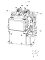
図1に、部品実装機10を示す。部品実装機10は、回路基材12に対する部品の実装作業を実行するための装置である。部品実装機10は、装置本体20、部品装着装置22、マークカメラ24、パーツカメラ26、部品供給装置28、ばら部品供給装置30、基材搬送保持装置32、カットアンドクリンチユニット(図3参照)34、ユニット移動装置(図3参照)36、制御装置(図7参照)38を備えている。なお、回路基材12として、回路基板、三次元構造の基材等が挙げられ、回路基板として、プリント配線板、プリント回路板等が挙げられる。 (A) Configuration of Component Mounter FIG. 1 shows acomponent mounter 10. The component mounter 10 is a device for performing the mounting operation of components on the circuit substrate 12. The component mounter 10 includes an apparatus body 20, a component mounting device 22, a mark camera 24, a part camera 26, a component supply device 28, a loose component supply device 30, a substrate conveyance and holding device 32, and a cut and clinch unit (see FIG. 3). 34, a unit moving device (see FIG. 3) 36 and a control device (see FIG. 7) 38. In addition, a circuit board, a base material of a three-dimensional structure, etc. are mentioned as circuit base material 12, A printed wiring board, a printed circuit board, etc. are mentioned as a circuit board.
図1に、部品実装機10を示す。部品実装機10は、回路基材12に対する部品の実装作業を実行するための装置である。部品実装機10は、装置本体20、部品装着装置22、マークカメラ24、パーツカメラ26、部品供給装置28、ばら部品供給装置30、基材搬送保持装置32、カットアンドクリンチユニット(図3参照)34、ユニット移動装置(図3参照)36、制御装置(図7参照)38を備えている。なお、回路基材12として、回路基板、三次元構造の基材等が挙げられ、回路基板として、プリント配線板、プリント回路板等が挙げられる。 (A) Configuration of Component Mounter FIG. 1 shows a
装置本体20は、フレーム部40と、そのフレーム部40に上架されたビーム部42とによって構成されている。なお、以下の説明において、装置本体20の幅方向をX方向と称し、装置本体20の前後方向をY方向と称し、鉛直方向をZ方向と称する。
The apparatus body 20 is constituted by a frame portion 40 and a beam portion 42 mounted on the frame portion 40. In the following description, the width direction of the device body 20 is referred to as the X direction, the front-rear direction of the device body 20 is referred to as the Y direction, and the vertical direction is referred to as the Z direction.
部品装着装置22は、ビーム部42に配設されており、2台の作業ヘッド60,62と作業ヘッド移動装置64とを有している。各作業ヘッド60,62の下端面には、図2に示すように、吸着ノズル66が設けられており、その吸着ノズル66によって部品を吸着保持する。また、作業ヘッド移動装置64は、X方向移動装置68とY方向移動装置70とZ方向移動装置72とを有している。そして、X方向移動装置68とY方向移動装置70とによって、2台の作業ヘッド60,62は、一体的にフレーム部40上の任意の位置に移動させられる。また、各作業ヘッド60,62は、スライダ74,76に着脱可能に装着されており、Z方向移動装置72は、スライダ74,76を個別に上下方向に移動させる。つまり、作業ヘッド60,62は、Z方向移動装置72によって、個別に上下方向に移動させられる。
The component mounting device 22 is disposed in the beam unit 42 and has two working heads 60 and 62 and a working head moving device 64. As shown in FIG. 2, suction nozzles 66 are provided on the lower end surfaces of the work heads 60 and 62, and the suction nozzles 66 suction and hold components. Further, the working head moving device 64 has an X direction moving device 68, a Y direction moving device 70, and a Z direction moving device 72. The two working heads 60 and 62 are integrally moved to an arbitrary position on the frame portion 40 by the X-direction moving device 68 and the Y-direction moving device 70. The working heads 60 and 62 are detachably mounted on the sliders 74 and 76, and the Z-direction moving device 72 moves the sliders 74 and 76 in the vertical direction separately. In other words, the work heads 60 and 62 are individually moved in the vertical direction by the Z-direction moving device 72.
また、マークカメラ24は、図2に示すように、下方を向いた状態でスライダ74に取り付けられている。これにより、マークカメラ24は、作業ヘッド60とともに、X方向,Y方向およびZ方向に移動させられ、フレーム部40上の任意の位置を撮像する。パーツカメラ26は、図1に示すように、フレーム部40上の部品供給装置28と基材搬送保持装置32との間に、上を向いた状態で配設されている。これにより、パーツカメラ26は、作業ヘッド60,62の吸着ノズル66に保持された部品を撮像する。
Further, as shown in FIG. 2, the mark camera 24 is attached to the slider 74 in a state of facing downward. Thereby, the mark camera 24 is moved in the X direction, the Y direction, and the Z direction together with the working head 60 to pick up an arbitrary position on the frame unit 40. As shown in FIG. 1, the parts camera 26 is disposed between the parts supply device 28 on the frame 40 and the base material conveyance and holding device 32 so as to face upward. Thus, the part camera 26 picks up an image of the part held by the suction nozzle 66 of the working head 60, 62.
部品供給装置28は、フレーム部40の前後方向での一方側の端部に配設されている。部品供給装置28は、トレイ型部品供給装置86とフィーダ型部品供給装置(図7参照)88とを有している。トレイ型部品供給装置86は、トレイ上に載置された状態の部品を供給する装置である。フィーダ型部品供給装置88は、テープフィーダ、スティックフィーダ(図示省略)によって部品を供給する装置である。
The component supply device 28 is disposed at one end of the frame portion 40 in the front-rear direction. The component supply device 28 has a tray type component supply device 86 and a feeder type component supply device (see FIG. 7) 88. The tray-type component supply device 86 is a device for supplying components in a state of being placed on the tray. The feeder type component supply device 88 is a device that supplies components by a tape feeder and a stick feeder (not shown).
ばら部品供給装置30は、フレーム部40の前後方向での他方側の端部に配設されている。ばら部品供給装置30は、ばらばらに散在された状態の複数の部品を整列させて、整列させた状態で部品を供給する装置である。つまり、任意の姿勢の複数の部品を、所定の姿勢に整列させて、所定の姿勢の部品を供給する装置である。
The bulk parts supply device 30 is disposed at the other end of the frame portion 40 in the front-rear direction. The loose parts supply device 30 is a device for aligning a plurality of parts in a loosely scattered state and supplying the parts in an aligned state. That is, it is an apparatus which aligns a plurality of parts of an arbitrary posture to a predetermined posture and supplies the components of the predetermined posture.
なお、部品供給装置28および、ばら部品供給装置30によって供給される部品として、電子回路部品,太陽電池の構成部品,パワーモジュールの構成部品等が挙げられる。また、電子回路部品には、リードを有する部品,リードを有さない部品等が有る。
Examples of components supplied by the component supply device 28 and the bulk component supply device 30 include electronic circuit components, components of a solar cell, components of a power module, and the like. Further, there are electronic circuit parts including parts having leads, parts not having leads, and the like.
基材搬送保持装置32は、フレーム部40の前後方向の中央に配設されており、図3に示すように、搬送装置100とクランプ装置102とを有している。搬送装置100は、回路基材12を搬送する装置であり、1対のガイドレール106,108を有している。1対のガイドレール106,108は、X方向に延びるように配設されており、互いに平行とされている。
The base material conveyance and holding device 32 is disposed at the center of the frame portion 40 in the front-rear direction, and includes a conveyance device 100 and a clamp device 102 as shown in FIG. The transfer apparatus 100 is an apparatus for transferring the circuit substrate 12 and has a pair of guide rails 106 and 108. The pair of guide rails 106 and 108 are disposed to extend in the X direction and are parallel to each other.
各ガイドレール106,108のX方向における一端部側には、第1コンベアベルト110が、X方向に延びるように巻き掛けられており、他端部側には、第2コンベアベルト112が、X方向に延びるように巻き掛けられている。そして、第1コンベアベルト110は、電磁モータ114の駆動により、図3での時計回りに周回し、第2コンベアベルト112は、電磁モータ116の駆動により、第1コンベアベルト110と同じ方向に周回する。
The first conveyor belt 110 is wound so as to extend in the X direction on one end side in the X direction of each of the guide rails 106 and 108, and the second conveyor belt 112 is connected to the other end side. It is wound to extend in the direction. Then, the first conveyor belt 110 orbits clockwise in FIG. 3 by driving the electromagnetic motor 114, and the second conveyor belt 112 orbits in the same direction as the first conveyor belt 110 by driving the electromagnetic motor 116. Do.
これにより、1対のガイドレール106,108の第1コンベアベルト110に支持された回路基材12が、部品実装機10に搬入され、1対のガイドレール106,108の第2コンベアベルト112に支持された回路基材12が、部品実装機10から搬出される。このため、第1コンベアベルト110が配設されている側を上流側と記載し、第2コンベアベルト112が配設されている側を下流側と記載する。なお、第1コンベアベルト110と第2コンベアベルト112とは、回路基材12の長さ寸法より長い距離、X方向において離間しており、第1コンベアベルト110と第2コンベアベルト112との間に、クランプ装置102が配設されている。
As a result, the circuit substrate 12 supported by the first conveyor belt 110 of the pair of guide rails 106 and 108 is carried into the mounter 10 and is moved to the second conveyor belt 112 of the pair of guide rails 106 and 108. The supported circuit base 12 is carried out of the mounter 10. Therefore, the side on which the first conveyor belt 110 is disposed is referred to as the upstream side, and the side on which the second conveyor belt 112 is disposed is referred to as the downstream side. The first conveyor belt 110 and the second conveyor belt 112 are separated in the X direction by a distance longer than the length dimension of the circuit substrate 12, and between the first conveyor belt 110 and the second conveyor belt 112. The clamp device 102 is disposed on the
また、ガイドレール108の第1コンベアベルト110が配設されている側の端部には、シャトル118が配設されている。シャトル118は、ガイドレール108に沿ってスライド可能に配設されており、シャトル118が上流側から下流側に向かってスライドすることで、第1コンベアベルト110により搬入された回路基材12が、クランプ装置102を経由して、第2コンベアベルト112まで搬送される。
Further, a shuttle 118 is disposed at an end of the guide rail 108 on which the first conveyor belt 110 is disposed. The shuttle 118 is disposed slidably along the guide rail 108, and the circuit substrate 12 carried in by the first conveyor belt 110 is moved by the shuttle 118 sliding from the upstream side toward the downstream side, It is conveyed to the second conveyor belt 112 via the clamp device 102.
また、クランプ装置102は、上述したように、第1コンベアベルト110と第2コンベアベルト112との間に配設されている。そして、クランプ装置102は、第1コンベアベルト110と第2コンベアベルト112との間に搬送されてきた回路基材12をクランプする。なお、回路基材12がクランプ装置102によりクランプされる位置が、回路基材12に対する作業位置となる。
In addition, the clamp device 102 is disposed between the first conveyor belt 110 and the second conveyor belt 112 as described above. The clamp device 102 clamps the circuit substrate 12 conveyed between the first conveyor belt 110 and the second conveyor belt 112. The position where the circuit base 12 is clamped by the clamp device 102 is the working position for the circuit base 12.
つまり、基材搬送保持装置32では、回路基材12が、第1コンベアベルト110により部品実装機10に搬入され、その搬入された回路基材12が、シャトル118により、第1コンベアベルト110と第2コンベアベルト112との間に搬送される。次に、第1コンベアベルト110と第2コンベアベルト112との間において、回路基材12は、クランプ装置102によりクランプされ、回路基材12に対する作業が行われる。続いて、回路基材12に対する作業が終了すると、クランプ装置102のクランプが解除され、回路基材12が、シャトル118により第2コンベアベルト112の上まで搬送される。そして、回路基材12は、第2コンベアベルト112によって部品実装機10から搬出される。このように、基材搬送保持装置32は、回路基材12の部品実装機10への搬入、作業位置での回路基材12のクランプ、回路基材12の部品実装機10からの搬出を行う。
That is, in the substrate transport holding device 32, the circuit substrate 12 is carried into the component mounting machine 10 by the first conveyor belt 110, and the circuit substrate 12 carried in is carried by the shuttle 118 with the first conveyor belt 110. It is conveyed between the second conveyor belt 112 and the like. Next, between the first conveyor belt 110 and the second conveyor belt 112, the circuit substrate 12 is clamped by the clamp device 102, and an operation is performed on the circuit substrate 12. Subsequently, when the operation on the circuit substrate 12 is completed, the clamp of the clamp device 102 is released, and the circuit substrate 12 is conveyed by the shuttle 118 onto the second conveyor belt 112. Then, the circuit base 12 is carried out of the mounter 10 by the second conveyor belt 112. As described above, the base material transport and holding device 32 carries in the circuit base 12 to the component mounter 10, clamps the circuit base 12 at the work position, and carries out the circuit base 12 from the component mounter 10. .
なお、基材搬送保持装置32は、ガイドレール106,108の間の距離(以下、「レール間距離」と記載する)を変更する変更機構120を有しており、レール間距離を変更することで、種々のサイズの回路基材12を搬送することが可能とされている。詳しくは、ガイドレール108は、変更機構120により、ガイドレール106に対して平行な状態でスライド可能に保持されている。そして、ガイドレール108が、電磁モータ122の駆動によりスライドすることで、レール間距離が変更される。これにより、基材搬送保持装置32は、種々のサイズの回路基材12を搬送することが可能とされている。なお、電磁モータ122には、エンコーダが設けられており、エンコーダによる検出値に基づくフィードバック制御が実行されることで、レール間距離が任意の距離に変更される。
In addition, the base material conveyance holding apparatus 32 has the change mechanism 120 which changes the distance between the guide rails 106 and 108 (hereinafter referred to as "distance between the rails"), and changes the distance between the rails. Thus, it is possible to transport circuit substrates 12 of various sizes. Specifically, the guide rail 108 is slidably held parallel to the guide rail 106 by the change mechanism 120. Then, the guide rail 108 slides by the drive of the electromagnetic motor 122 to change the distance between the rails. Thus, the substrate transport and holding device 32 can transport the circuit substrates 12 of various sizes. The electromagnetic motor 122 is provided with an encoder, and the distance between the rails is changed to an arbitrary distance by performing feedback control based on the detected value by the encoder.
また、基材搬送保持装置32の内部に、カットアンドクリンチユニット34とユニット移動装置36とが配設されている。ユニット移動装置36は、基材搬送保持装置32のハウジング128を構成する底板の上面に固定されており、ユニット移動装置36の作動により、カットアンドクリンチユニット34が任意の位置に移動する。なお、カットアンドクリンチユニット34は、基材搬送保持装置32により搬送、及び保持される回路基材12より下方において移動する。
Further, a cut and clinch unit 34 and a unit moving device 36 are disposed inside the base material conveyance and holding device 32. The unit moving device 36 is fixed to the upper surface of the bottom plate constituting the housing 128 of the base material transfer and holding device 32, and the cut and clinch unit 34 is moved to an arbitrary position by the operation of the unit moving device 36. The cut and clinch unit 34 moves below the circuit substrate 12 which is transported and held by the substrate transport and holding device 32.
詳しくは、カットアンドクリンチユニット34は、図4に示すように、1対のスライド体130を有している。1対のスライド体130は、X方向に延びるように配設されたスライドレール132によって、スライド可能に支持されている。そして、スライド体130が、電磁モータ(図7参照)134の駆動により、スライドすることで、1対のスライド体130の間の距離が制御可能に変更される。
Specifically, the cut and clinch unit 34 has a pair of slide bodies 130, as shown in FIG. The pair of slide bodies 130 is slidably supported by slide rails 132 arranged to extend in the X direction. Then, as the slide body 130 slides by the drive of the electromagnetic motor (see FIG. 7), the distance between the pair of slide bodies 130 is controllably changed.
また、1対のスライド体130の各々は、固定部136と可動部138とを含み、固定部136において、スライドレール132にスライド可能に保持されている。また、可動部138は固定部136によってX方向にスライド可能に保持されている。そして、可動部138は、電磁モータ(図7参照)140の駆動により、固定部136に対してX方向に制御可能にスライドする。
Further, each of the pair of slide bodies 130 includes a fixed portion 136 and a movable portion 138, and is slidably held by the slide rail 132 at the fixed portion 136. Further, the movable portion 138 is held slidably by the fixed portion 136 in the X direction. Then, the movable portion 138 slides in a controllable manner in the X direction with respect to the fixed portion 136 by the drive of the electromagnetic motor (see FIG. 7) 140.
また、固定部136の上端部は、図5に示すように、先細形状とされており、その上端部を上下方向に貫通するように、第1挿入穴150が形成されている。また、第1挿入穴150の上端面への開口縁は、固定刃152とされている。一方、可動部138の上端部も、先細形状とされており、その上端部には、L字型に屈曲された屈曲部154が形成されている。屈曲部154は、固定部136の上端面の上方に延び出している。また、固定部136の上端面に開口する第1挿入穴150は、屈曲部154によって覆われているが、屈曲部154には、第1挿入穴150と対向するように、第2挿入穴156が形成されている。なお、第2挿入穴156の屈曲部154の下端面への開口縁は、可動刃158とされている。
Further, as shown in FIG. 5, the upper end portion of the fixing portion 136 is tapered, and the first insertion hole 150 is formed so as to penetrate the upper end portion in the vertical direction. Further, an opening edge to the upper end surface of the first insertion hole 150 is a fixed blade 152. On the other hand, the upper end portion of the movable portion 138 is also tapered, and an L-shaped bent portion 154 is formed at the upper end portion. The bent portion 154 extends above the upper end surface of the fixed portion 136. Further, although the first insertion hole 150 opened at the upper end surface of the fixing portion 136 is covered by the bending portion 154, the second insertion hole 156 is opposed to the first insertion hole 150 at the bending portion 154. Is formed. The opening edge of the second insertion hole 156 to the lower end surface of the bending portion 154 is a movable blade 158.
また、ユニット移動装置36は、図6に示すように、X方向移動装置160とY方向移動装置162とZ方向移動装置164と自転装置166とを有している。X方向移動装置160は、スライドレール170,171とXスライダ172とを含む。スライドレール170,171は、X方向に延びるように配設されており、Xスライダ172は、スライドレール170,171にスライド可能に保持されている。そして、Xスライダ172は、電磁モータ(図7参照)174の駆動により、X方向に移動する。
Moreover, the unit moving apparatus 36 has the X direction moving apparatus 160, the Y direction moving apparatus 162, the Z direction moving apparatus 164, and the autorotation apparatus 166, as shown in FIG. The X-direction moving device 160 includes slide rails 170 and 171 and an X-slider 172. The slide rails 170 and 171 are disposed to extend in the X direction, and the X slider 172 is slidably held by the slide rails 170 and 171. Then, the X slider 172 moves in the X direction by driving of the electromagnetic motor (see FIG. 7) 174.
Y方向移動装置162は、スライドレール176とYスライダ178とを含む。スライドレール176は、Y方向に延びるようにXスライダ172に配設されており、Yスライダ178は、スライドレール176にスライド可能に保持されている。そして、Yスライダ178は、電磁モータ(図7参照)180の駆動により、Y方向に移動する。Z方向移動装置164は、スライドレール182とZスライダ184とを含む。スライドレール182は、Z方向に延びるようにYスライダ178に配設されており、Zスライダ184は、スライドレール182にスライド可能に保持されている。そして、Zスライダ184は、電磁モータ(図7参照)186の駆動により、Z方向に移動する。
The Y-direction moving device 162 includes a slide rail 176 and a Y-slider 178. The slide rail 176 is disposed on the X slider 172 so as to extend in the Y direction, and the Y slider 178 is slidably held by the slide rail 176. Then, the Y slider 178 moves in the Y direction by driving of the electromagnetic motor (see FIG. 7) 180. The Z direction moving device 164 includes a slide rail 182 and a Z slider 184. The slide rail 182 is disposed on the Y slider 178 so as to extend in the Z direction, and the Z slider 184 is slidably held by the slide rail 182. Then, the Z-slider 184 moves in the Z direction by driving of the electromagnetic motor (see FIG. 7) 186.
また、自転装置166は、概して円盤状の回転テーブル188を有している。回転テーブル188は、それの軸心を中心に回転可能にZスライダ184に支持されており、電磁モータ(図7参照)189の駆動により、回転する。そして、回転テーブル188の上に、カットアンドクリンチユニット34が配設されている。このような構造により、カットアンドクリンチユニット34は、X方向移動装置160、Y方向移動装置162、Z方向移動装置164によって、任意の位置に移動するとともに、自転装置166によって、任意の角度に自転する。これにより、カットアンドクリンチユニット34を、基材搬送保持装置32のクランプ装置102によって保持された回路基材12の下方において、任意の位置に位置決めすることが可能となる。
In addition, the rotation device 166 has a generally disk-shaped rotary table 188. The rotary table 188 is supported by the Z-slider 184 so as to be rotatable about its axis, and is rotated by the drive of an electromagnetic motor (see FIG. 7) 189. The cut and clinch unit 34 is disposed on the rotary table 188. With such a structure, the cut and clinch unit 34 is moved to an arbitrary position by the X-direction moving device 160, the Y-direction moving device 162, and the Z-direction moving device 164, and rotated by an autorotation device 166 at an arbitrary angle. Do. As a result, the cut and clinch unit 34 can be positioned at any position below the circuit substrate 12 held by the clamp device 102 of the substrate conveyance and holding device 32.
また、制御装置38は、図7に示すように、コントローラ190、複数の駆動回路192、画像処理装置196を備えている。複数の駆動回路192は、上記作業ヘッド60,62、作業ヘッド移動装置64、トレイ型部品供給装置86、フィーダ型部品供給装置88、ばら部品供給装置30、搬送装置100、クランプ装置102、電磁モータ134,140,174,180,186,189に接続されている。コントローラ190は、CPU,ROM,RAM等を備え、コンピュータを主体とするものであり、複数の駆動回路192に接続されている。これにより、部品装着装置22、部品供給装置28等の作動が、コントローラ190によって制御される。また、コントローラ190は、画像処理装置196にも接続されている。画像処理装置196は、マークカメラ24およびパーツカメラ26によって得られた画像データを処理するものであり、コントローラ190は、画像データから各種情報を取得する。
Further, as shown in FIG. 7, the control device 38 includes a controller 190, a plurality of drive circuits 192, and an image processing device 196. The plurality of drive circuits 192 includes the working heads 60 and 62, the working head moving device 64, the tray type component supplying device 86, the feeder type component supplying device 88, the bulk component supplying device 30, the conveying device 100, the clamp device 102, and an electromagnetic motor It is connected to 134, 140, 174, 180, 186 and 189. The controller 190 includes a CPU, a ROM, a RAM, and the like, is mainly composed of a computer, and is connected to a plurality of drive circuits 192. Thus, the controller 190 controls the operation of the component mounting device 22, the component supply device 28, and the like. The controller 190 is also connected to the image processing apparatus 196. The image processing device 196 processes image data obtained by the mark camera 24 and the part camera 26. The controller 190 obtains various information from the image data.
(B)部品実装機の作動
部品実装機10では、上述した構成によって、基材搬送保持装置32に保持された回路基材12に対して部品の装着作業が行われる。部品実装機10は、種々の部品を回路基材12に装着することが可能であるが、リード部品(図5参照)200を回路基材12に装着する場合について、以下に説明する。 (B) Operation of Component Mounter In thecomponent mounter 10, the component mounting operation is performed on the circuit substrate 12 held by the substrate conveyance and holding device 32 according to the above-described configuration. The component mounter 10 is capable of mounting various components on the circuit substrate 12, but the case of mounting the lead component (see FIG. 5) 200 on the circuit substrate 12 will be described below.
部品実装機10では、上述した構成によって、基材搬送保持装置32に保持された回路基材12に対して部品の装着作業が行われる。部品実装機10は、種々の部品を回路基材12に装着することが可能であるが、リード部品(図5参照)200を回路基材12に装着する場合について、以下に説明する。 (B) Operation of Component Mounter In the
具体的には、回路基材12が、搬送装置100により作業位置まで搬送され、その位置において、クランプ装置102によって固定的に保持される。次に、マークカメラ24が、回路基材12の上方に移動し、回路基材12を撮像する。これにより、回路基材12の保持位置等に関する情報が得られる。また、部品供給装置28若しくは、ばら部品供給装置30が、所定の供給位置において、リード部品200を供給する。そして、作業ヘッド60,62の何れかが、部品の供給位置の上方に移動し、吸着ノズル66によって、リード部品200の部品本体部(図5参照)202を吸着保持する。
Specifically, the circuit substrate 12 is transported by the transport device 100 to the work position, and is held fixed by the clamp device 102 at that position. Next, the mark camera 24 moves above the circuit substrate 12 and images the circuit substrate 12. Thereby, the information regarding the holding position of the circuit base 12 etc. is obtained. Further, the component supply device 28 or the bulk component supply device 30 supplies the lead component 200 at a predetermined supply position. Then, either of the working heads 60 and 62 moves above the supply position of the component, and the suction nozzle 66 sucks and holds the component body portion (see FIG. 5) 202 of the lead component 200.
続いて、リード部品200を保持した作業ヘッド60,62が、パーツカメラ26の上方に移動し、パーツカメラ26によって、吸着ノズル66に保持されたリード部品200が撮像される。これにより、部品の保持位置等に関する情報が得られる。続いて、リード部品200を保持した作業ヘッド60,62が、回路基材12の上方に移動し、回路基材12の保持位置の誤差,部品の保持位置の誤差等を補正する。そして、吸着ノズル66により吸着保持されたリード部品200のリード(図5参照)204が、回路基材12に形成された貫通穴(図5参照)206に挿入される。この際、その貫通穴206の下方には、カットアンドクリンチユニット34が移動している。
Subsequently, the working heads 60 and 62 holding the lead component 200 move above the parts camera 26, and the part camera 26 captures an image of the lead component 200 held by the suction nozzle 66. Thus, information on the holding position of the part can be obtained. Subsequently, the working heads 60 and 62 holding the lead component 200 move to the upper side of the circuit base 12 to correct an error in the holding position of the circuit base 12 and an error in the holding position of the component. Then, the lead (see FIG. 5) 204 of the lead component 200 suctioned and held by the suction nozzle 66 is inserted into the through hole 206 (see FIG. 5) formed in the circuit substrate 12. At this time, the cut and clinch unit 34 is moved below the through hole 206.
具体的には、カットアンドクリンチユニット34において、1対のスライド体130の可動部138の第2挿入穴156の間の距離が、回路基材12に形成された2つの貫通穴206の間の距離と同じとなるように、1対のスライド体130の間の距離が変更される。そして、X方向移動装置160及びY方向移動装置162の作動により、スライド体130の第2挿入穴156のXY方向での座標と、回路基材12の貫通穴206のXY方向での座標とが一致するように、カットアンドクリンチユニット34が移動する。これにより、カットアンドクリンチユニット34が、XY方向に沿って移動することで、スライド体130の第2挿入穴156と、回路基材12の貫通穴206とが上下方向に重なる。
Specifically, in the cut and clinch unit 34, the distance between the second insertion holes 156 of the movable portions 138 of the pair of slide bodies 130 is between the two through holes 206 formed in the circuit substrate 12. The distance between the pair of slide bodies 130 is changed to be the same as the distance. Then, by the operation of the X direction moving device 160 and the Y direction moving device 162, the coordinates of the second insertion hole 156 of the slide body 130 in the XY direction and the coordinates of the through hole 206 of the circuit substrate 12 in the XY direction The cut and clinch unit 34 moves so as to coincide. As a result, the cut and clinch unit 34 moves in the X and Y directions, whereby the second insertion hole 156 of the slide body 130 and the through hole 206 of the circuit substrate 12 overlap in the vertical direction.
次に、カットアンドクリンチユニット34は、Z方向移動装置164の作動により、可動部138の上面が回路基材12の下面に接触、若しくは、回路基材12の下面より僅か下方に位置するように、上昇する。このように、X方向移動装置160,Y方向移動装置162,Z方向移動装置164の作動が制御されることで、スライド体130の第2挿入穴156と、回路基材12の貫通穴206とが重なった状態で、カットアンドクリンチユニット34が回路基材12の貫通穴206の下方に配置される。
Next, in the cut and clinch unit 34, the upper surface of the movable portion 138 is in contact with the lower surface of the circuit substrate 12 or positioned slightly below the lower surface of the circuit substrate 12 by the operation of the Z direction moving device 164. ,To rise. Thus, by controlling the operations of the X-direction moving device 160, the Y-direction moving device 162, and the Z-direction moving device 164, the second insertion hole 156 of the slide body 130 and the through hole 206 of the circuit substrate 12 are obtained. The cut and clinch unit 34 is disposed below the through hole 206 of the circuit substrate 12 in a state where the
そして、吸着ノズル66により吸着保持されたリード部品200のリード204が、回路基材12の貫通穴206に挿入されると、そのリード204の先端部は、図5に示すように、カットアンドクリンチユニット34の可動部138の第2挿入穴156を経て、固定部136の第1挿入穴150に挿入される。次に、リード204の先端部が、固定部136の第1挿入穴150に挿入されると、可動部138が電磁モータ140の作動によりスライドする。
Then, when the lead 204 of the lead component 200 sucked and held by the suction nozzle 66 is inserted into the through hole 206 of the circuit substrate 12, the tip of the lead 204 is cut and clinched as shown in FIG. The second insertion hole 156 of the movable portion 138 of the unit 34 is inserted into the first insertion hole 150 of the fixed portion 136. Next, when the tip of the lead 204 is inserted into the first insertion hole 150 of the fixed part 136, the movable part 138 slides by the operation of the electromagnetic motor 140.
これにより、リード204が、第1挿入穴150の固定刃152と第2挿入穴156の可動刃158とによって切断される。そして、切断によるリード204の新たな先端部は、可動部138のスライドに伴って屈曲する。これにより、リード204の貫通穴206からの抜けが防止された状態で、リード部品200が回路基材12に装着される。
Thereby, the lead 204 is cut by the fixed blade 152 of the first insertion hole 150 and the movable blade 158 of the second insertion hole 156. Then, the new tip of the lead 204 due to the cutting bends as the movable portion 138 slides. Thus, the lead component 200 is attached to the circuit base 12 in a state in which the lead 204 is prevented from coming off the through hole 206.
このように、部品実装機10では、回路基材12の貫通穴206と、カットアンドクリンチユニット34の第2挿入穴156とが上下方向で重なった状態で、貫通穴206にリード204が挿入される。そして、カットアンドクリンチユニット34によって、リード204が切断及び屈曲され、リード部品200が回路基材12に装着される。なお、回路基材12の貫通穴206と、カットアンドクリンチユニット34の第2挿入穴156とが上下方向で重なるように、カットアンドクリンチユニット34が移動する際に、貫通穴206の位置に基づいて、ユニット移動装置36の作動が制御される。
Thus, in the component mounting machine 10, the lead 204 is inserted into the through hole 206 in a state where the through hole 206 of the circuit substrate 12 and the second insertion hole 156 of the cut and clinch unit 34 overlap in the vertical direction. Ru. Then, the lead 204 is cut and bent by the cut and clinch unit 34, and the lead component 200 is attached to the circuit base 12. When the cut and clinch unit 34 moves such that the through hole 206 of the circuit substrate 12 and the second insertion hole 156 of the cut and clinch unit 34 overlap in the vertical direction, the position of the through hole 206 is determined. Thus, the operation of the unit moving device 36 is controlled.
詳しくは、リード部品200の挿入予定の貫通穴206のXY方向での座標が、装着プログラムとして制御装置38に記憶されている。そして、そのXY方向での貫通穴206の座標が、回路基材12の保持位置の誤差等に基づいて補正される。その補正された貫通穴206の座標が、リード204の挿入予定位置となる。そして、その挿入予定位置と、カットアンドクリンチユニット34の第2挿入穴156のXY方向での座標とが一致するように、ユニット移動装置36の作動が制御される。これにより、回路基材12の貫通穴206と、カットアンドクリンチユニット34の第2挿入穴156とが上下方向で重なり、リード204が第2挿入穴156に挿入されることで、リード204が適切に切断及び屈曲される。
Specifically, the coordinates in the XY direction of the through hole 206 into which the lead part 200 is to be inserted are stored in the control device 38 as a mounting program. Then, the coordinates of the through hole 206 in the XY direction are corrected based on an error of the holding position of the circuit substrate 12 or the like. The corrected coordinates of the through hole 206 become the planned insertion position of the lead 204. Then, the operation of the unit moving device 36 is controlled so that the planned insertion position coincides with the coordinate in the XY direction of the second insertion hole 156 of the cut and clinch unit 34. As a result, the through hole 206 of the circuit substrate 12 and the second insertion hole 156 of the cut and clinch unit 34 overlap in the vertical direction, and the lead 204 is inserted into the second insertion hole 156, whereby the lead 204 is appropriate. Cut and bent.
(C)レール間距離変更時のユニット移動装置の制御
また、部品実装機10では、基材搬送保持装置32において、上述したように、レール間距離を変更することが可能であり、種々のサイズの回路基材12を搬送し、種々のサイズの回路基材12に対して装着作業を行うことが可能である。ただし、ユニット移動装置36によるカットアンドクリンチユニット34の可動範囲が、レール間距離の変更に伴って、基材搬送保持装置32の1対のガイドレール106,108の間の外側にはみ出る場合がある。このような場合に、カットアンドクリンチユニット34が、基材搬送保持装置32のガイドレール108,ハウジング128を構成する壁面等に干渉する虞がある。 (C) Control of unit moving device when changing inter-rail distance Further, in thecomponent mounting machine 10, as described above, it is possible to change the inter-rail distance in the base material conveyance and holding device 32, various sizes It is possible to transport the circuit substrate 12 and to perform the mounting operation on the circuit substrates 12 of various sizes. However, the movable range of the cut-and-clinch unit 34 by the unit moving device 36 may protrude outside between the pair of guide rails 106 and 108 of the substrate transport holding device 32 as the distance between the rails is changed. . In such a case, there is a possibility that the cut and clinch unit 34 interferes with the guide rail 108 of the base material conveyance and holding device 32, the wall surface constituting the housing 128, and the like.
また、部品実装機10では、基材搬送保持装置32において、上述したように、レール間距離を変更することが可能であり、種々のサイズの回路基材12を搬送し、種々のサイズの回路基材12に対して装着作業を行うことが可能である。ただし、ユニット移動装置36によるカットアンドクリンチユニット34の可動範囲が、レール間距離の変更に伴って、基材搬送保持装置32の1対のガイドレール106,108の間の外側にはみ出る場合がある。このような場合に、カットアンドクリンチユニット34が、基材搬送保持装置32のガイドレール108,ハウジング128を構成する壁面等に干渉する虞がある。 (C) Control of unit moving device when changing inter-rail distance Further, in the
詳しくは、1対のガイドレール106,108が最も離間している状態において、図8に示すように、ユニット移動装置36は、1対のガイドレール106,108の下方において、1対のガイドレール106,108の間に位置するように、配置されている。つまり、レール間距離Lが最も長い状態において、ユニット移動装置36は、1対のガイドレール106,108の間のXY座標の範囲内に位置するように、配置されている。これにより、レール間距離Lが最も長い状態のガイドレール106,108に支持される回路基材12の下方の全域で、カットアンドクリンチユニット34が移動し、回路基材12の貫通穴206に挿入されたリード204を切断・屈曲できる。
Specifically, in the state where the pair of guide rails 106 and 108 are most separated, as shown in FIG. 8, the unit moving device 36 has the pair of guide rails below the pair of guide rails 106 and 108. It is arrange | positioned so that it may be located between 106,108. That is, in the state in which the distance L between the rails is the longest, the unit moving device 36 is disposed so as to be located within the range of XY coordinates between the pair of guide rails 106 and 108. As a result, the cut and clinch unit 34 moves across the entire area under the circuit base 12 supported by the guide rails 106 and 108 with the longest inter-rail distance L, and is inserted into the through hole 206 of the circuit base 12. The lead 204 can be cut and bent.
ただし、図9に示すように、レール間距離Lが短くされると、ユニット移動装置36の一部が、1対のガイドレール106,108の間の外側に位置する。詳しくは、ユニット移動装置36を構成するX方向移動装置160のスライドレール170は、1対のガイドレール106,108の間に位置するが、スライドレール171は、1対のガイドレール106,108の間の外側に位置する。そして、X方向移動装置160のXスライダ172のスライドレール171側の端部も、1対のガイドレール106,108の間の外側に位置する。これにより、ユニット移動装置36を構成するY方向移動装置162のスライドレール176のスライドレール171側の端部も、1対のガイドレール106,108の間の外側に位置する。
However, as shown in FIG. 9, when the distance L between the rails is shortened, a part of the unit moving device 36 is located outside between the pair of guide rails 106 and 108. Specifically, the slide rails 170 of the X-direction moving device 160 constituting the unit moving device 36 are located between the pair of guide rails 106 and 108, while the slide rail 171 is of the pair of guide rails 106 and 108. Located outside between. And the end by the side of slide rail 171 of X slider 172 of X direction movement device 160 is also located outside between a pair of guide rails 106 and 108. Thus, the end on the slide rail 171 side of the slide rail 176 of the Y-direction moving device 162 constituting the unit moving device 36 is also located outside between the pair of guide rails 106 and 108.
このため、カットアンドクリンチユニット34がY方向移動装置162によりスライドレール171に近づく方向に移動すると、カットアンドクリンチユニット34がガイドレール108等の基材搬送保持装置32と干渉する虞がある(図9の点線参照)。このようなことに鑑みて、部品実装機10では、装着作業時に、レール間距離に基づいて、ユニット移動装置36の作動が制御され、カットアンドクリンチユニット34と基材搬送保持装置32との干渉が防止される。
For this reason, when the cut and clinch unit 34 is moved in the direction approaching the slide rail 171 by the Y direction moving device 162, the cut and clinch unit 34 may interfere with the base material transport holding device 32 such as the guide rail 108 (see FIG. See the dotted line in 9). In view of such a thing, in the component mounting machine 10, the operation of the unit moving device 36 is controlled based on the distance between the rails at the time of mounting operation, and the interference between the cut and clinch unit 34 and the substrate transport holding device 32. Is prevented.
具体的には、回路基材12の種類の変更に伴ってレール間距離が変更された際,生産開始時などのタイミングで、コントローラ190がレール間距離を演算する。なお、レール間距離は、ガイドレール108をスライドさせる変更機構120の電磁モータ122の出力値、つまり、電磁モータ122に設けられたエンコーダに基づいて、演算される。そして、コントローラ190は、レール間距離に基づいて、カットアンドクリンチユニット34と基材搬送保持装置32との干渉を避けて、カットアンドクリンチユニット34を移動させた際の第2挿入穴156の移動範囲(以下、「挿入穴移動範囲」と記載する)を演算する。
Specifically, when the distance between the rails is changed in accordance with the change of the type of the circuit substrate 12, the controller 190 calculates the distance between the rails at the timing when production starts or the like. The inter-rail distance is calculated based on the output value of the electromagnetic motor 122 of the change mechanism 120 that slides the guide rail 108, that is, the encoder provided in the electromagnetic motor 122. Then, the controller 190 moves the second insertion hole 156 when moving the cut and clinch unit 34 while avoiding the interference between the cut and clinch unit 34 and the base material conveyance and holding device 32 based on the distance between the rails. A range (hereinafter referred to as “insertion hole movement range”) is calculated.
なお、挿入穴移動範囲は、X方向移動装置160及びY方向移動装置162によるカットアンドクリンチユニット34の移動時の範囲であり、XY方向での座標により示される。また、挿入穴移動範囲は、レール間距離だけでなく、カットアンドクリンチユニット34の外寸,基材搬送保持装置32の内寸,基材搬送保持装置32とカットアンドクリンチユニット34とのクリアランスなども考慮して演算される。そして、リード部品200の装着作業時に、挿入穴移動範囲を超えてカットアンドクリンチユニット34が移動しないように、ユニット移動装置36の作動が制御される。
The insertion hole moving range is a range when the cut and clinch unit 34 is moved by the X direction moving device 160 and the Y direction moving device 162, and is indicated by coordinates in the XY direction. In addition, the insertion hole movement range is not limited to the distance between the rails, and the outer size of the cut and clinch unit 34, the inner size of the base material transport and holding device 32, the clearance between the base material transport and hold device 32 and the cut and clinch unit 34, etc. Is also calculated in consideration of Then, the operation of the unit moving device 36 is controlled so that the cut and clinch unit 34 does not move beyond the insertion hole movement range when the lead component 200 is mounted.
詳しくは、上述したように、リード部品200の挿入予定の貫通穴206のXY方向での座標が、装着プログラムとして制御装置38に記憶されており、そのXY方向での座標が、回路基材12の保持位置の誤差等に基づいて補正される。そして、その補正された座標(以下、「補正済挿入予定座標」と記載する)と、カットアンドクリンチユニット34の第2挿入穴156のXY方向での座標とが一致するように、ユニット移動装置36の作動が制御される。
Specifically, as described above, the coordinate in the XY direction of the through hole 206 to be inserted into the lead part 200 is stored in the control device 38 as a mounting program, and the coordinate in the XY direction is the circuit substrate 12 It corrects based on the error etc. of the holding position of. Then, the unit moving device is arranged such that the corrected coordinates (hereinafter referred to as “corrected planned insertion coordinates”) and the coordinates in the XY direction of the second insertion hole 156 of the cut and clinch unit 34 coincide with each other. The operation of 36 is controlled.
なお、制御プログラムとして、制御装置38に記憶されている貫通穴206のXY方向での座標は、回路基材12のサイズに応じて設定されているため、通常、補正済挿入予定座標は挿入穴移動範囲の内部に位置する。ただし、貫通穴206のXY方向での座標が、制御プログラムとして入力される際に、間違った値が入力される場合がある。このような場合には、補正済挿入予定座標が挿入穴移動範囲の外部に位置する虞がある。また、制御プログラムとしての貫通穴206の座標は、回路基材12の保持位置等に基づいて補正されるが、この際、貫通穴206の座標が大幅に補正されると、補正済挿入予定座標が挿入穴移動範囲の外部に位置する虞がある。
In addition, since the coordinate in the XY direction of the through hole 206 stored in the control device 38 as the control program is set according to the size of the circuit substrate 12, the corrected planned insertion coordinate is usually the insertion hole It is located inside the movement range. However, when the coordinate in the XY direction of the through hole 206 is input as a control program, an incorrect value may be input. In such a case, the corrected planned insertion coordinates may be located outside the insertion hole movement range. Further, the coordinates of the through hole 206 as a control program are corrected based on the holding position of the circuit substrate 12, etc. At this time, if the coordinates of the through hole 206 are largely corrected, the corrected planned insertion coordinates May be located outside the insertion hole movement range.
このように、補正済挿入予定座標が挿入穴移動範囲の外部に位置する場合に、カットアンドクリンチユニット34の第2挿入穴156を補正済挿入予定座標に移動させると、基材搬送保持装置32とカットアンドクリンチユニット34とが干渉する。一方、補正済挿入予定座標が挿入穴移動範囲の内部に位置する場合に、カットアンドクリンチユニット34の第2挿入穴156を補正済挿入予定座標に移動させても、基材搬送保持装置32とカットアンドクリンチユニット34とは干渉しない。
As described above, when the second insertion hole 156 of the cut-and-clinch unit 34 is moved to the corrected planned insertion coordinates when the corrected planned insertion coordinates are positioned outside the insertion hole movement range, the base material conveyance and holding device 32 And the cut and clinch unit 34 interfere with each other. On the other hand, even if the second insertion hole 156 of the cut and clinch unit 34 is moved to the corrected planned insertion coordinate when the corrected planned insertion coordinate is positioned inside the insertion hole movement range, It does not interfere with the cut and clinch unit 34.
そこで、ユニット移動装置36の作動が制御される前に、補正済挿入予定座標が挿入穴移動範囲の内部に位置しているか否かが、コントローラ190によって判断される。そして、補正済挿入予定座標が挿入穴移動範囲の内部に位置していると判断された場合に、カットアンドクリンチユニット34の第2挿入穴156が補正済挿入予定座標に移動するように、ユニット移動装置36の作動が制御される。
Therefore, before the operation of the unit moving device 36 is controlled, the controller 190 determines whether the corrected planned insertion coordinates are located within the insertion hole movement range. Then, when it is determined that the corrected planned insertion coordinates are positioned within the insertion hole movement range, the unit is moved so that the second insertion hole 156 of the cut and clinch unit 34 moves to the corrected planned insertion coordinates. The operation of the transfer device 36 is controlled.
一方、補正済挿入予定座標が挿入穴移動範囲の外部に位置していると判断された場合に、ユニット移動装置36の作動は制御されず、つまり、カットアンドクリンチユニット34は移動せず、部品実装機10の表示パネル(図1参照)210にエラー画面が表示される。なお、エラー画面には、基材搬送保持装置32とカットアンドクリンチユニット34とが干渉する虞があるため、装着作業を中断している旨のコメントが表示される。このように、レール間距離に基づいて、ユニット移動装置36の作動を制御することで、基材搬送保持装置32とカットアンドクリンチユニット34との干渉を防止することが可能となる。
On the other hand, when it is determined that the corrected planned insertion coordinates are located outside the insertion hole movement range, the operation of the unit moving device 36 is not controlled, that is, the cut and clinch unit 34 does not move, and the parts An error screen is displayed on the display panel (see FIG. 1) 210 of the mounting machine 10. Since there is a possibility that the base material conveyance and holding device 32 and the cut and clinch unit 34 interfere with each other on the error screen, a comment indicating that the mounting operation is interrupted is displayed. As described above, by controlling the operation of the unit moving device 36 based on the distance between the rails, it is possible to prevent the interference between the base material conveyance and holding device 32 and the cut and clinch unit 34.
なお、制御装置38のコントローラ190は、図7に示すように、取得部220と作動制御部222とを有しており、作動制御部222は、判断部224を含む。取得部220は、レール間距離を取得する機能部である。判断部224は、レール間距離に基づいて、挿入穴移動範囲を演算し、補正済挿入予定座標が挿入穴移動範囲の内部に位置しているか否かを判断する機能部である。つまり、判断部224は、ユニット移動装置36の作動制御時に、基材搬送保持装置32とカットアンドクリンチユニット34とが干渉するか否かを判断する機能部である。作動制御部222は、補正済挿入予定座標が挿入穴移動範囲の内部に位置している場合に、カットアンドクリンチユニット34の第2挿入穴156が補正済挿入予定座標に移動するように、ユニット移動装置36の作動を制御する機能部である。また、作動制御部222は、補正済挿入予定座標が挿入穴移動範囲の外部に位置している場合に、カットアンドクリンチユニット34を移動させず、エラー画面を表示パネルに表示する機能部である。
The controller 190 of the control device 38 includes an acquisition unit 220 and an operation control unit 222 as shown in FIG. 7, and the operation control unit 222 includes a determination unit 224. The acquisition unit 220 is a functional unit that acquires the distance between the rails. The determination unit 224 is a functional unit that calculates the insertion hole movement range based on the inter-rail distance and determines whether the corrected planned insertion coordinates are located inside the insertion hole movement range. That is, the determination unit 224 is a functional unit that determines whether or not the base material conveyance and holding device 32 and the cut and clinch unit 34 interfere with each other when controlling the operation of the unit moving device 36. The operation control unit 222 is a unit that moves the second insertion hole 156 of the cut and clinch unit 34 to the corrected planned insertion coordinates when the corrected planned insertion coordinates are located inside the insertion hole movement range. It is a functional unit that controls the operation of the moving device 36. In addition, the operation control unit 222 is a functional unit that displays an error screen on the display panel without moving the cut and clinch unit 34 when the corrected planned insertion coordinates are located outside the insertion hole movement range. .
ちなみに、部品実装機10は、対基板作業システムの一例である。基材搬送保持装置32は、搬送保持装置の一例である。カットアンドクリンチユニット34は、作業装置の一例である。ユニット移動装置36は、移動装置の一例である。制御装置38は、制御装置の一例である。ガイドレール106,108は、レールの一例である。変更機構120は、変更機構の一例である。取得部220は、取得部の一例である。作動制御部222は、作動制御部の一例である。判断部224は、判断部の一例である。
Incidentally, the component mounting machine 10 is an example of a board-to-board operation system. The substrate conveyance and holding device 32 is an example of a conveyance and holding device. The cut and clinch unit 34 is an example of a working device. The unit moving device 36 is an example of a moving device. The control device 38 is an example of a control device. The guide rails 106 and 108 are an example of the rails. The change mechanism 120 is an example of a change mechanism. The acquisition unit 220 is an example of an acquisition unit. The operation control unit 222 is an example of the operation control unit. The determination unit 224 is an example of a determination unit.
なお、本発明は、上記実施例に限定されるものではなく、当業者の知識に基づいて種々の変更、改良を施した種々の態様で実施することが可能である。具体的には、例えば、上記実施例では、変更機構120の電磁モータ122の出力値に基づいて、レール間距離が演算されているが、ガイドレール108をマークカメラ24により撮像し、その撮像により得られる撮像データに基づいて、レール間距離が演算されてもよい。また、作業予定の回路基材12のサイズ等が制御プログラムとして入力されている場合には、回路基材12のサイズ等に基づいて、レール間距離が演算されてもよい。
The present invention is not limited to the above-described embodiments, and can be implemented in various modes in which various changes and improvements are made based on the knowledge of those skilled in the art. Specifically, for example, in the above embodiment, the inter-rail distance is calculated based on the output value of the electromagnetic motor 122 of the change mechanism 120, but the guide rail 108 is imaged by the mark camera 24 and The inter-rail distance may be calculated based on the obtained imaging data. In addition, when the size or the like of the circuit base 12 scheduled to be worked is input as a control program, the inter-rail distance may be calculated based on the size or the like of the circuit base 12.
また、上記実施例では、カットアンドクリンチユニット34に本発明が適用されているが、基材搬送保持装置32に保持された回路基材12に対して、下面側から作業を行う装置であれば、種々の作業装置に本発明を適用することが可能である。具体的には、例えば、回路基材12の貫通穴206に挿入されたリード部品200のリード204に、はんだ等の粘性流体を塗布する作業装置に、本発明を適用してもよい。また、回路基材12の下面側からのネジ締め作業等の工作作業を行う作業装置に本発明を適用してもよい。
Moreover, in the said Example, although this invention is applied to the cut and clinch unit 34, if it is an apparatus which works from the lower surface side with respect to the circuit base material 12 hold | maintained at the base-material conveyance holding apparatus 32. The present invention can be applied to various working devices. Specifically, for example, the present invention may be applied to a working device that applies a viscous fluid such as solder to the lead 204 of the lead component 200 inserted into the through hole 206 of the circuit substrate 12. In addition, the present invention may be applied to a working device that performs a working operation such as a screw tightening operation from the lower surface side of the circuit substrate 12.
また、上記実施例では、装着作業時に、レール間距離に基づいて、ユニット移動装置36の作動が制御されているが、作動動作確認時,メンテナンス時等に、レール間距離に基づいて、ユニット移動装置36の作動が制御されてもよい。具体的には、例えば、作業者がボタン操作等により、ユニット移動装置36を作動させている際に、カットアンドクリンチユニット34の第2挿入穴156が挿入穴移動範囲の外部に出る前に、コントローラ190が、ユニット移動装置36の作動を停止させてもよい。
Further, in the above embodiment, the operation of the unit moving device 36 is controlled based on the distance between the rails at the time of mounting work, but the unit movement based on the distance between the rails at the time of operation operation check, maintenance, etc. The operation of device 36 may be controlled. Specifically, for example, when the operator operates the unit moving device 36 by a button operation or the like, before the second insertion hole 156 of the cut and clinch unit 34 goes out of the insertion hole movement range, A controller 190 may deactivate the unit mover 36.
また、上記実施例では、レール間距離に基づいて挿入穴移動範囲が演算され、その挿入穴移動範囲を利用して、基材搬送保持装置32とカットアンドクリンチユニット34とが干渉するか否かが判断されているが、他の手法により、判断されてもよい。具体的には、例えば、レール間距離に基づいてガイドレール108などのカットアンドクリンチユニット34と干渉する虞のある部材の位置を演算し、その位置に基づいて、基材搬送保持装置32とカットアンドクリンチユニット34との干渉が判断されてもよい。
In the above embodiment, the insertion hole movement range is calculated based on the distance between the rails, and whether or not the base material conveyance and holding device 32 interferes with the cut and clinch unit 34 using the insertion hole movement range Is determined, but may be determined by other methods. Specifically, for example, based on the distance between the rails, the position of a member that may interfere with the cut and clinch unit 34 such as the guide rail 108 is calculated, and based on the position, the base material transport holding device 32 and the cut Interference with the and clinch unit 34 may be determined.
10:部品実装機(対基板作業システム) 32:基材搬送保持装置(搬送保持装置) 34:カットアンドクリンチユニット(作業装置) 36:ユニット移動装置(移動装置) 38:制御装置 106:ガイドレー(レール) 108:ガイドレール(レール) 120:変更機構 220:取得部 222:作動制御部 224:判断部
10: Component mounting machine (substrate-to-board operation system) 32: Base material conveyance and holding device (conveyance holding device) 34: Cut and clinch unit (working device) 36: Unit moving device (moving device) 38: Control device 106: Guideley (Rail) 108: Guide rail (rail) 120: Change mechanism 220: Acquisition unit 222: Operation control unit 224: Determination unit
Claims (3)
- 基板を支持する1対のレールと、前記1対のレールの間の距離を変更する変更機構とを有し、前記1対のレールに支持された基板を搬送し、その基板を作業位置において保持する搬送保持装置と、
前記搬送保持装置により保持された基板の下面側から、その基板に向かって作業を実行する作業装置と、
前記作業装置を移動させる移動装置と、
制御装置と
を備え、
前記制御装置が、
前記1対のレールの間の距離であるレール間距離を取得する取得部と、
前記取得部により取得されたレール間距離に基づいて、前記移動装置の作動を制御する作動制御部と
を有する対基板作業システム。 A pair of rails for supporting the substrate, and a changing mechanism for changing the distance between the pair of rails, transport the substrate supported by the pair of rails, and hold the substrate in the working position Transport holding device,
A working device for performing work toward the substrate from the lower surface side of the substrate held by the transport holding device;
A moving device for moving the work device;
Equipped with a controller and
The controller
An acquisition unit configured to acquire an inter-rail distance which is a distance between the pair of rails;
An operation control unit that controls an operation of the moving device based on the distance between the rails acquired by the acquisition unit. - 前記作動制御部が、
前記作業装置が前記搬送保持装置と干渉しないように、前記レール間距離に基づいて、前記移動装置の作動を制御する請求項1に記載の対基板作業システム。 The operation control unit
The substrate-to-board operation system according to claim 1, wherein the operation of the moving device is controlled based on the distance between the rails such that the operation device does not interfere with the transport and holding device. - 前記作動制御部が、
予め設定された設定位置に前記作業装置を移動させた場合に、前記作業装置が前記搬送保持装置と干渉するか否かを、前記レール間距離に基づいて判断する判断部を有し、
前記作業装置が前記搬送保持装置と干渉しないと判断された場合に、前記作業装置を前記設定位置に移動させるように、前記移動装置の作動を制御し、
前記作業装置が前記搬送保持装置と干渉すると判断された場合に、その旨を報知する請求項1または請求項2に記載の対基板作業システム。 The operation control unit
And a determination unit that determines whether the work device interferes with the transport holding device based on the distance between the rails when the work device is moved to a preset setting position,
The operation of the moving device is controlled to move the working device to the set position when it is determined that the working device does not interfere with the transport holding device.
The substrate-to-board operation system according to claim 1 or 2, wherein when it is determined that the work device interferes with the transport holding device, the fact is notified.
Priority Applications (5)
| Application Number | Priority Date | Filing Date | Title |
|---|---|---|---|
| CN201780095460.9A CN111165085B (en) | 2017-10-06 | 2017-10-06 | Substrate processing system |
| JP2019546492A JP6963021B2 (en) | 2017-10-06 | 2017-10-06 | Board work system |
| PCT/JP2017/036410 WO2019069438A1 (en) | 2017-10-06 | 2017-10-06 | Substrate work system |
| US16/646,617 US11382246B2 (en) | 2017-10-06 | 2017-10-06 | Substrate work system under adjustable rail spacing distance |
| EP17927938.5A EP3694302B1 (en) | 2017-10-06 | 2017-10-06 | Substrate work system |
Applications Claiming Priority (1)
| Application Number | Priority Date | Filing Date | Title |
|---|---|---|---|
| PCT/JP2017/036410 WO2019069438A1 (en) | 2017-10-06 | 2017-10-06 | Substrate work system |
Publications (1)
| Publication Number | Publication Date |
|---|---|
| WO2019069438A1 true WO2019069438A1 (en) | 2019-04-11 |
Family
ID=65994243
Family Applications (1)
| Application Number | Title | Priority Date | Filing Date |
|---|---|---|---|
| PCT/JP2017/036410 WO2019069438A1 (en) | 2017-10-06 | 2017-10-06 | Substrate work system |
Country Status (5)
| Country | Link |
|---|---|
| US (1) | US11382246B2 (en) |
| EP (1) | EP3694302B1 (en) |
| JP (1) | JP6963021B2 (en) |
| CN (1) | CN111165085B (en) |
| WO (1) | WO2019069438A1 (en) |
Families Citing this family (1)
| Publication number | Priority date | Publication date | Assignee | Title |
|---|---|---|---|---|
| JP7213433B2 (en) | 2018-04-18 | 2023-01-27 | パナソニックIpマネジメント株式会社 | Component mounting system and tape chip collection device |
Citations (6)
| Publication number | Priority date | Publication date | Assignee | Title |
|---|---|---|---|---|
| JPS6377191A (en) * | 1986-09-19 | 1988-04-07 | パイオニア株式会社 | Electronic componrnt attaching apparatus |
| JPH09219599A (en) * | 1996-02-13 | 1997-08-19 | Matsushita Electric Ind Co Ltd | Electronic parts mounting method and mounting machine |
| JP2000174499A (en) | 1998-12-03 | 2000-06-23 | Fujitsu Ltd | Electronic component mounting system |
| JP2008004856A (en) * | 2006-06-26 | 2008-01-10 | Matsushita Electric Ind Co Ltd | Member supporting method |
| JP2009094160A (en) * | 2007-10-04 | 2009-04-30 | Panasonic Corp | Part mounting device, control method and program |
| US20090295053A1 (en) * | 2008-05-30 | 2009-12-03 | Production Solutions, Inc. | Adjustable support tooling apparatus |
Family Cites Families (13)
| Publication number | Priority date | Publication date | Assignee | Title |
|---|---|---|---|---|
| JP2000165017A (en) * | 1998-11-25 | 2000-06-16 | Taiyo Yuden Co Ltd | Method and apparatus for machining ceramic green sheet |
| DE60038292T2 (en) * | 1999-05-21 | 2009-03-12 | Matsushita Electric Industrial Co., Ltd., Kadoma-shi | DEVICE AND METHOD FOR TRANSPORTING / HOLDING FLAT ELEMENTS |
| JP2002118398A (en) * | 2000-10-05 | 2002-04-19 | Fuji Mach Mfg Co Ltd | Method for detecting position of printed circuit board |
| JP4425855B2 (en) * | 2003-01-17 | 2010-03-03 | 富士機械製造株式会社 | Circuit board working machine and component supply method therefor |
| JP4570643B2 (en) * | 2006-05-25 | 2010-10-27 | 豊田スチールセンター株式会社 | Plate width measuring system and plate width measuring method |
| JP5003350B2 (en) * | 2007-08-23 | 2012-08-15 | パナソニック株式会社 | Electronic component mounting apparatus and electronic component mounting method |
| US8523161B2 (en) * | 2010-08-05 | 2013-09-03 | Hiwin Mikrosystem Corp. | Clamping mechanism automatically adaptable to change of thickness of printed circuit board |
| US10111370B2 (en) * | 2013-07-23 | 2018-10-23 | Fuji Corporation | Work machine |
| EP3088128B1 (en) * | 2013-12-27 | 2019-08-07 | FUJI Corporation | Component supply system |
| JP6285275B2 (en) * | 2014-04-30 | 2018-02-28 | 株式会社Screenホールディングス | Substrate processing apparatus and substrate processing method |
| TW201603483A (en) * | 2014-07-04 | 2016-01-16 | 晶越微波積體電路製造股份有限公司 | Production method for thermistor embedded crystal oscillator substrate |
| JP6678178B2 (en) * | 2015-09-04 | 2020-04-08 | 株式会社Fuji | Work machine |
| WO2018146880A1 (en) * | 2017-02-09 | 2018-08-16 | ボンドテック株式会社 | Component mounting system, resin shaping device, component mounting method, and resin shaping method |
-
2017
- 2017-10-06 JP JP2019546492A patent/JP6963021B2/en active Active
- 2017-10-06 CN CN201780095460.9A patent/CN111165085B/en active Active
- 2017-10-06 EP EP17927938.5A patent/EP3694302B1/en active Active
- 2017-10-06 US US16/646,617 patent/US11382246B2/en active Active
- 2017-10-06 WO PCT/JP2017/036410 patent/WO2019069438A1/en unknown
Patent Citations (6)
| Publication number | Priority date | Publication date | Assignee | Title |
|---|---|---|---|---|
| JPS6377191A (en) * | 1986-09-19 | 1988-04-07 | パイオニア株式会社 | Electronic componrnt attaching apparatus |
| JPH09219599A (en) * | 1996-02-13 | 1997-08-19 | Matsushita Electric Ind Co Ltd | Electronic parts mounting method and mounting machine |
| JP2000174499A (en) | 1998-12-03 | 2000-06-23 | Fujitsu Ltd | Electronic component mounting system |
| JP2008004856A (en) * | 2006-06-26 | 2008-01-10 | Matsushita Electric Ind Co Ltd | Member supporting method |
| JP2009094160A (en) * | 2007-10-04 | 2009-04-30 | Panasonic Corp | Part mounting device, control method and program |
| US20090295053A1 (en) * | 2008-05-30 | 2009-12-03 | Production Solutions, Inc. | Adjustable support tooling apparatus |
Also Published As
| Publication number | Publication date |
|---|---|
| CN111165085B (en) | 2021-08-24 |
| EP3694302A1 (en) | 2020-08-12 |
| EP3694302A4 (en) | 2020-10-14 |
| JPWO2019069438A1 (en) | 2019-12-26 |
| US20200229330A1 (en) | 2020-07-16 |
| CN111165085A (en) | 2020-05-15 |
| EP3694302B1 (en) | 2023-09-20 |
| US11382246B2 (en) | 2022-07-05 |
| JP6963021B2 (en) | 2021-11-05 |
Similar Documents
| Publication | Publication Date | Title |
|---|---|---|
| WO2017068682A1 (en) | System for performing work on substrate and insertion method | |
| CN108029231B (en) | Substrate processing machine and recognition method | |
| JP6219838B2 (en) | Component mounter | |
| WO2017060974A1 (en) | Cutting/bending device and cutting device | |
| JP6648132B2 (en) | Board work machine and recognition method | |
| CN114271043B (en) | Component Mounting Machine | |
| WO2019069438A1 (en) | Substrate work system | |
| JP7242920B2 (en) | Cutting/bending device | |
| US10959361B2 (en) | Substrate working machine | |
| JP6678178B2 (en) | Work machine | |
| CN108353533B (en) | Bending device | |
| WO2018142492A1 (en) | Coordinate data generation device and coordinate data generation method | |
| JP6654978B2 (en) | Board work machine | |
| JP6726310B2 (en) | Component mounter | |
| JP2017092175A (en) | Component mounter, component suction method | |
| CN107926151B (en) | Required precision setting device | |
| JP6016683B2 (en) | Method for detecting height of mounting head in electronic component mounting apparatus and electronic component mounting apparatus | |
| JPWO2020021657A1 (en) | Surface mounter | |
| JP2004319943A (en) | Component mounting device and component mounting method | |
| JPWO2018016025A1 (en) | Board work machine | |
| WO2015033403A1 (en) | Mounting line | |
| JPWO2017006439A1 (en) | Component mounting equipment | |
| JP2023016498A (en) | Board working device and board working method | |
| JP2019161143A (en) | Position confirmation method, position adjustment method, position confirmation device, and position adjustment device | |
| JP2022118841A (en) | Work machine and interference avoiding method |
Legal Events
| Date | Code | Title | Description |
|---|---|---|---|
| 121 | Ep: the epo has been informed by wipo that ep was designated in this application |
Ref document number: 17927938 Country of ref document: EP Kind code of ref document: A1 |
|
| ENP | Entry into the national phase |
Ref document number: 2019546492 Country of ref document: JP Kind code of ref document: A |
|
| NENP | Non-entry into the national phase |
Ref country code: DE |
|
| ENP | Entry into the national phase |
Ref document number: 2017927938 Country of ref document: EP Effective date: 20200506 |