WO2019235352A1 - Structure de poussée de couvercle - Google Patents
Structure de poussée de couvercle Download PDFInfo
- Publication number
- WO2019235352A1 WO2019235352A1 PCT/JP2019/021526 JP2019021526W WO2019235352A1 WO 2019235352 A1 WO2019235352 A1 WO 2019235352A1 JP 2019021526 W JP2019021526 W JP 2019021526W WO 2019235352 A1 WO2019235352 A1 WO 2019235352A1
- Authority
- WO
- WIPO (PCT)
- Prior art keywords
- lid
- urging
- link
- spring body
- housing
- Prior art date
Links
- 230000001105 regulatory effect Effects 0.000 claims description 8
- 239000000945 filler Substances 0.000 claims description 5
- 239000000446 fuel Substances 0.000 claims description 3
- 238000003780 insertion Methods 0.000 claims description 2
- 230000037431 insertion Effects 0.000 claims description 2
- 230000000052 comparative effect Effects 0.000 description 9
- 238000010586 diagram Methods 0.000 description 6
- 230000000149 penetrating effect Effects 0.000 description 6
- 238000004804 winding Methods 0.000 description 6
- 238000013461 design Methods 0.000 description 4
- 238000000034 method Methods 0.000 description 4
- 230000002159 abnormal effect Effects 0.000 description 3
- 239000002783 friction material Substances 0.000 description 3
- 238000012360 testing method Methods 0.000 description 3
- 230000001771 impaired effect Effects 0.000 description 2
- 239000011347 resin Substances 0.000 description 2
- 229920005989 resin Polymers 0.000 description 2
- 125000002066 L-histidyl group Chemical group [H]N1C([H])=NC(C([H])([H])[C@](C(=O)[*])([H])N([H])[H])=C1[H] 0.000 description 1
- 206010044565 Tremor Diseases 0.000 description 1
- 230000002238 attenuated effect Effects 0.000 description 1
- 230000008878 coupling Effects 0.000 description 1
- 238000010168 coupling process Methods 0.000 description 1
- 238000005859 coupling reaction Methods 0.000 description 1
- 230000007613 environmental effect Effects 0.000 description 1
- 239000002828 fuel tank Substances 0.000 description 1
- 238000010348 incorporation Methods 0.000 description 1
- 238000002347 injection Methods 0.000 description 1
- 239000007924 injection Substances 0.000 description 1
- 239000000463 material Substances 0.000 description 1
- 239000000203 mixture Substances 0.000 description 1
- 239000007779 soft material Substances 0.000 description 1
Images


Classifications
-
- E—FIXED CONSTRUCTIONS
- E05—LOCKS; KEYS; WINDOW OR DOOR FITTINGS; SAFES
- E05B—LOCKS; ACCESSORIES THEREFOR; HANDCUFFS
- E05B83/00—Vehicle locks specially adapted for particular types of wing or vehicle
- E05B83/28—Locks for glove compartments, console boxes, fuel inlet covers or the like
- E05B83/34—Locks for glove compartments, console boxes, fuel inlet covers or the like for fuel inlet covers essentially flush with the vehicle surface
-
- B—PERFORMING OPERATIONS; TRANSPORTING
- B60—VEHICLES IN GENERAL
- B60K—ARRANGEMENT OR MOUNTING OF PROPULSION UNITS OR OF TRANSMISSIONS IN VEHICLES; ARRANGEMENT OR MOUNTING OF PLURAL DIVERSE PRIME-MOVERS IN VEHICLES; AUXILIARY DRIVES FOR VEHICLES; INSTRUMENTATION OR DASHBOARDS FOR VEHICLES; ARRANGEMENTS IN CONNECTION WITH COOLING, AIR INTAKE, GAS EXHAUST OR FUEL SUPPLY OF PROPULSION UNITS IN VEHICLES
- B60K1/00—Arrangement or mounting of electrical propulsion units
- B60K1/04—Arrangement or mounting of electrical propulsion units of the electric storage means for propulsion
-
- B—PERFORMING OPERATIONS; TRANSPORTING
- B60—VEHICLES IN GENERAL
- B60K—ARRANGEMENT OR MOUNTING OF PROPULSION UNITS OR OF TRANSMISSIONS IN VEHICLES; ARRANGEMENT OR MOUNTING OF PLURAL DIVERSE PRIME-MOVERS IN VEHICLES; AUXILIARY DRIVES FOR VEHICLES; INSTRUMENTATION OR DASHBOARDS FOR VEHICLES; ARRANGEMENTS IN CONNECTION WITH COOLING, AIR INTAKE, GAS EXHAUST OR FUEL SUPPLY OF PROPULSION UNITS IN VEHICLES
- B60K15/00—Arrangement in connection with fuel supply of combustion engines or other fuel consuming energy converters, e.g. fuel cells; Mounting or construction of fuel tanks
- B60K15/03—Fuel tanks
- B60K15/04—Tank inlets
- B60K15/05—Inlet covers
-
- B—PERFORMING OPERATIONS; TRANSPORTING
- B60—VEHICLES IN GENERAL
- B60L—PROPULSION OF ELECTRICALLY-PROPELLED VEHICLES; SUPPLYING ELECTRIC POWER FOR AUXILIARY EQUIPMENT OF ELECTRICALLY-PROPELLED VEHICLES; ELECTRODYNAMIC BRAKE SYSTEMS FOR VEHICLES IN GENERAL; MAGNETIC SUSPENSION OR LEVITATION FOR VEHICLES; MONITORING OPERATING VARIABLES OF ELECTRICALLY-PROPELLED VEHICLES; ELECTRIC SAFETY DEVICES FOR ELECTRICALLY-PROPELLED VEHICLES
- B60L53/00—Methods of charging batteries, specially adapted for electric vehicles; Charging stations or on-board charging equipment therefor; Exchange of energy storage elements in electric vehicles
- B60L53/10—Methods of charging batteries, specially adapted for electric vehicles; Charging stations or on-board charging equipment therefor; Exchange of energy storage elements in electric vehicles characterised by the energy transfer between the charging station and the vehicle
- B60L53/14—Conductive energy transfer
- B60L53/16—Connectors, e.g. plugs or sockets, specially adapted for charging electric vehicles
-
- F—MECHANICAL ENGINEERING; LIGHTING; HEATING; WEAPONS; BLASTING
- F16—ENGINEERING ELEMENTS AND UNITS; GENERAL MEASURES FOR PRODUCING AND MAINTAINING EFFECTIVE FUNCTIONING OF MACHINES OR INSTALLATIONS; THERMAL INSULATION IN GENERAL
- F16C—SHAFTS; FLEXIBLE SHAFTS; ELEMENTS OR CRANKSHAFT MECHANISMS; ROTARY BODIES OTHER THAN GEARING ELEMENTS; BEARINGS
- F16C11/00—Pivots; Pivotal connections
- F16C11/04—Pivotal connections
-
- F—MECHANICAL ENGINEERING; LIGHTING; HEATING; WEAPONS; BLASTING
- F16—ENGINEERING ELEMENTS AND UNITS; GENERAL MEASURES FOR PRODUCING AND MAINTAINING EFFECTIVE FUNCTIONING OF MACHINES OR INSTALLATIONS; THERMAL INSULATION IN GENERAL
- F16F—SPRINGS; SHOCK-ABSORBERS; MEANS FOR DAMPING VIBRATION
- F16F1/00—Springs
- F16F1/02—Springs made of steel or other material having low internal friction; Wound, torsion, leaf, cup, ring or the like springs, the material of the spring not being relevant
- F16F1/04—Wound springs
-
- B—PERFORMING OPERATIONS; TRANSPORTING
- B60—VEHICLES IN GENERAL
- B60K—ARRANGEMENT OR MOUNTING OF PROPULSION UNITS OR OF TRANSMISSIONS IN VEHICLES; ARRANGEMENT OR MOUNTING OF PLURAL DIVERSE PRIME-MOVERS IN VEHICLES; AUXILIARY DRIVES FOR VEHICLES; INSTRUMENTATION OR DASHBOARDS FOR VEHICLES; ARRANGEMENTS IN CONNECTION WITH COOLING, AIR INTAKE, GAS EXHAUST OR FUEL SUPPLY OF PROPULSION UNITS IN VEHICLES
- B60K15/00—Arrangement in connection with fuel supply of combustion engines or other fuel consuming energy converters, e.g. fuel cells; Mounting or construction of fuel tanks
- B60K15/03—Fuel tanks
- B60K15/04—Tank inlets
- B60K15/05—Inlet covers
- B60K2015/0515—Arrangements for closing or opening of inlet cover
- B60K2015/053—Arrangements for closing or opening of inlet cover with hinged connection to the vehicle body
-
- Y—GENERAL TAGGING OF NEW TECHNOLOGICAL DEVELOPMENTS; GENERAL TAGGING OF CROSS-SECTIONAL TECHNOLOGIES SPANNING OVER SEVERAL SECTIONS OF THE IPC; TECHNICAL SUBJECTS COVERED BY FORMER USPC CROSS-REFERENCE ART COLLECTIONS [XRACs] AND DIGESTS
- Y02—TECHNOLOGIES OR APPLICATIONS FOR MITIGATION OR ADAPTATION AGAINST CLIMATE CHANGE
- Y02T—CLIMATE CHANGE MITIGATION TECHNOLOGIES RELATED TO TRANSPORTATION
- Y02T10/00—Road transport of goods or passengers
- Y02T10/60—Other road transportation technologies with climate change mitigation effect
- Y02T10/70—Energy storage systems for electromobility, e.g. batteries
-
- Y—GENERAL TAGGING OF NEW TECHNOLOGICAL DEVELOPMENTS; GENERAL TAGGING OF CROSS-SECTIONAL TECHNOLOGIES SPANNING OVER SEVERAL SECTIONS OF THE IPC; TECHNICAL SUBJECTS COVERED BY FORMER USPC CROSS-REFERENCE ART COLLECTIONS [XRACs] AND DIGESTS
- Y02—TECHNOLOGIES OR APPLICATIONS FOR MITIGATION OR ADAPTATION AGAINST CLIMATE CHANGE
- Y02T—CLIMATE CHANGE MITIGATION TECHNOLOGIES RELATED TO TRANSPORTATION
- Y02T10/00—Road transport of goods or passengers
- Y02T10/60—Other road transportation technologies with climate change mitigation effect
- Y02T10/7072—Electromobility specific charging systems or methods for batteries, ultracapacitors, supercapacitors or double-layer capacitors
-
- Y—GENERAL TAGGING OF NEW TECHNOLOGICAL DEVELOPMENTS; GENERAL TAGGING OF CROSS-SECTIONAL TECHNOLOGIES SPANNING OVER SEVERAL SECTIONS OF THE IPC; TECHNICAL SUBJECTS COVERED BY FORMER USPC CROSS-REFERENCE ART COLLECTIONS [XRACs] AND DIGESTS
- Y02—TECHNOLOGIES OR APPLICATIONS FOR MITIGATION OR ADAPTATION AGAINST CLIMATE CHANGE
- Y02T—CLIMATE CHANGE MITIGATION TECHNOLOGIES RELATED TO TRANSPORTATION
- Y02T90/00—Enabling technologies or technologies with a potential or indirect contribution to GHG emissions mitigation
- Y02T90/10—Technologies relating to charging of electric vehicles
- Y02T90/14—Plug-in electric vehicles
Definitions
- the present invention relates to a lid biasing structure.
- FIG. 14 shows a vehicle lid device disclosed in the prior application (Patent Document 1) of the present applicant.
- the lid device 7 shown in FIG. 1 includes a housing 1 that defines an oil filler space, a closed position that is rotatably supported by a link member with respect to the housing 1, and a second position that is in the middle of opening from the closed position.
- the lid 2 that can be switched to the fully open position, and the lid 2 is urged in the closing direction at the closed position, and when the lid 2 is rotated from the closing direction to the second position, the urging direction in the second position
- a biasing member 6 that can be switched from the second position to the fully open position by a biasing force.
- the link member is constituted by the first link 4A and the second link 4B to restrict the pivot trajectory of the lid in a compact manner, or the urging member between the links 4A and 4B. 6 is applied so that the lid 2 does not rattle due to the urging force in the closed position and the fully open position, or when the lid is unlocked in the closed position, the push lifter 16 slightly resists the urging force.
- the lid can be turned and operated with a hand or the like.
- the lid urging structure when the lid is operated to rotate against the urging force from the fully open position to the second position in the lid closing operation, the urging direction of the spring body as the urging member is reversed, Since it is simultaneously rotated by the urging force from the second position to the closed position, it strongly collides with the push lifter, and the lid tends to flutter or generate abnormal noise. This is a serious problem because a predetermined torque is ensured as the torque of the spring body so that the lid does not flutter inadvertently at the closed position.
- the lid in the lid biasing structure B, the lid is switched from the closed position to the first position in the middle of opening from the closed position, the second position in the opening direction, and the fully opened position.
- the first position is a position where the lid momentarily stops when the lid is rotated from the second position by the biasing force, or the lid is rotated from the closed position to the opening direction against the biasing force. When this is done, the operating force is instantaneously unnecessary.
- the lid opening angle is as small as about 10 degrees.
- the lid in the operation of closing the lid, the lid is rotated from the second position to the first position by the urging force, stopped momentarily at the first position, and then rotated again to the closed position by the urging force.
- the lid opening angle at the first position is as small as about 10 degrees, the lid hits the push lifter at a high speed, and noise is likely to be generated, and the high-class feeling is also impaired.
- the rotational speed of the lid is attenuated by utilizing the frictional resistance of the friction material, which is an elastic member or a soft material.
- the friction material is not stable because the mechanical properties of the friction material change depending on the wear of the surface generating the frictional force and the environmental temperature.
- the object of the present invention is to solve the above-mentioned problems, improve the feeling of lid opening / closing operation compared to the prior art, and to make a flap or noise when closing the lid without depending on the frictional force.
- the purpose is to make it difficult to occur. Other purposes will be clarified in the description below.
- the present invention provides a housing in which an oil filler port or an electric charging port is disposed inside an opening, a closed position in which the housing is rotatably supported by a link member, and the housing is closed.
- the lid is switched to the first position in the middle of opening, the second position in the opening direction, and the fully opened position, and the lid is urged in the closing direction at the closed position, and the closing direction (this closing direction and Is either the closed position, the vicinity of the first position between the closed position and the first position, or the first position (hereinafter, the same) to the second position when the rotation operation is performed against the biasing force.
- bias biasing structure that allows switching from a second position to a fully open position by a biasing force
- biasing member is disposed between the link member and the housing.
- Each spring is composed of multiple spring bodies The balance causes the lid to rotate from the closed position to the first position or the vicinity of the first position against the urging force and the lid to rotate from the first position or from the vicinity of the first position to the closed position. It is characterized by adjusting the biasing force to bias as much as possible.
- the lid biasing structure of the present invention is switched by rotating from a closed position where the lid closes the opening of the housing, a first position in the middle of opening from the closed position, a second position in the opening direction, and a fully opened position. It is done.
- FIG. 13 shows a structure A using two spring bodies 6 and 7 as a product of the present invention, a structure B using a single spring body 6 as a comparative product, a structure using a single spring body 7 or a spring body 7A.
- the lid urging structure A is an invention as in the embodiment.
- the lid urging structures B, C, and C1 are comparative products that differ from the embodiment in that the lid urging structures B, C, and C1 are configured by a single spring body.
- the lid is switched from the closed position to the second position in the middle of opening and the fully opened position.
- the lid is operated to rotate against the urging force from the fully opened position to the second position in the lid closing operation, the urging direction of the spring body is reversed, and the lid is attached from the second position to the closed position. Since it is rotated all at once by the force, it strongly collides with the push lifter 16 of Patent Document 1. This point becomes a serious problem when a predetermined torque is ensured as the torque of the spring body so that the lid does not flutter carelessly at the closed position (Problem 1 of the present invention).
- the lid is switched to the closed position, the first position being opened from the closed position, the second position in the opening direction, and the fully opened position.
- the second position is the same as the structure C or C1
- the lid opening angles when the urging direction of the spring body is reversed the lid is operated from the fully open position to the closing direction against the urging force.
- This is the lid position when the biasing direction of the spring body is reversed and this time it is rotated in the closing direction by the biasing force.
- the lid opening angle is about 50 degrees.
- the first position is a position where the lid momentarily stops when the lid is rotated from the second position by the biasing force, or the lid rotates from the closed position to the opening direction against the biasing force. This is a position at which no operating force is required when a dynamic operation is performed.
- the lid opening angle is about 25 degrees for the structure A, and the lid opening angle is about 10 degrees for the structure B.
- the lid opening angle at the first position is largely corrected to about 25 degrees, so that such a problem can be solved or alleviated, and flapping and hitting sound are reduced. This increases the sense of quality and is effective in preventing finger pinching.
- the lid is closed from the first position to the first position or the vicinity of the first position” and “the lid is closed from the first position or the vicinity of the first position” are specified, that is, other than the “first position”.
- the reason for adding “near the first position” is as follows.
- FIG. 13 for example, in the lid closing operation, when the lid is rotated from the second position to the first position (the lid opening angle is about 25 degrees) by the biasing force of the spring body, the lid is instantaneously moved at the first position.
- the lid opening angle is about 20 degrees and the urging force is again applied in the closing direction.
- the time lag associated with the reversal of the energizing direction is taken into consideration.
- the present invention described above may be embodied as in the following aspects.
- the link member includes a first link and a second link, one end of which is pivotally supported on the back side of the lid, and the other end of which is pivotally supported on the inside of the housing, and the spring body includes the first link and the second link.
- the first spring body is disposed between housings, and the second spring body is disposed between the second link and the housing side.
- the lid urging structure includes a first spring body disposed between the first link and the housing, and a second spring body disposed between the second link and the housing. As can be inferred from FIG.
- the lid opening angle at the first position can be set larger than when the first and second spring bodies are used alone. It is the composition which becomes.
- the lid opening angle at the first position can be set larger as compared with the configuration in which each spring body is used alone, as can be seen from FIG. Therefore, for example, in the lid closing operation, it becomes easy to alleviate the impact at the time of closing in proportion to the distance from the first position to the closing position or the rotation angle, and improve the sense of quality by reducing the conventional flapping and hitting sound. it can.
- (C) A structure provided in the housing and having a base that pivotally supports the first link and the second link and restricts a corresponding end side of the spring body. According to this aspect, it is possible to favorably maintain the handleability of the lid, the ease of incorporation into the housing, and the appearance characteristics by pivotally supporting each link between the lid and the base and arranging the spring body.
- the first link is connected to the upper plate portion that is pivotally supported by the lid, an intermediate plate portion that is coupled to the upper plate portion and pivotally supported to the base, and is coupled to the intermediate plate portion in the width direction.
- a first spring body disposed between an inner wall of the base provided to face the arm portion and the arm portion.
- the second link includes a plate body pivotally supported by the lid and the base, a pair of leg portions projecting from the lower side of the plate body with a space therebetween, and a rear side of the leg portion.
- the second spring body is disposed on the inner surface side of the base, and one end of the second spring body is regulated to fit into the groove portion of the one leg portion, and the other end is formed on the base. It is the structure by which insertion restriction is carried out to the fitting hole which was provided and penetrated in the vertical direction.
- each link is simple and the position of one end of each spring body is regulated to the corresponding link, and the other end is regulated to the corresponding part of the base, so that the assembly is performed.
- the spring body is a coil spring.
- This coil spring includes a torsion spring having a winding portion. According to this aspect, the use of a simple and versatile coil spring as the spring body can be carried out at a reduced cost.
- the magnitude of the urging force for urging to rotate from the position or the vicinity of the first position to the closed position can be set optimally, so that the feeling of the lid opening / closing operation can be improved.
- (A) is a schematic diagram showing the lid in the closed position
- (b) is a schematic diagram showing in the fully open position of the lid. It is the lid reverse view seen from the lid back side in the closed position of the said lid.
- (A) And (b) is the front view and right end view which show the state of the lid of FIG. 2 upside down. It is a model operation diagram for demonstrating the motion of the said lid.
- (A) And (b) is a principal part enlarged view which shows typically the lid urging
- (A) And (b) is a principal part enlarged view which shows typically the lid urging
- FIG. 1 is a configuration diagram of the comparative product 1 using only the first spring body
- (b) is a configuration diagram of the comparative product 2 using only the second spring body. is there. It is a graph which shows the relationship of the lid front end operating force (N) and the lid opening angle (deg) of the said Example goods and the comparison goods 1 and 2.
- FIG. It is sectional drawing which shows the lid urging
- FIGS. 5A and 5B and FIGS. 6A and 6B are schematically illustrated due to restrictions on drawing.
- the lid urging structure includes a substantially container-shaped housing 1 having an upper opening that defines an oil filler port, and a link member for the housing 1.
- a lid 2 that is connected and supported by the 1 link 4 and the second link 5 to close the opening of the housing 1, a first position that is in the middle of opening from the closed position, a second position that is further in the opening direction, and a fully open position.
- the lid 2 is urged in the closing direction at the closed position, and when the lid 2 is rotated against the urging force from the closing direction to the second position, the urging direction is reversed and is applied from the second position to the fully opened position.
- a plurality of spring bodies 6 and 7 which are urging members that can be switched by urging force are provided.
- the lid 2 is rotatably supported by the base 3 provided in the housing 1 via the first link 4 and the second link 5.
- the first spring body 6 is disposed between the first link 4 and the base 3
- the second spring body 7 is disposed between the second link 5 and the base 3.
- the lid 2 is locked at the closed position shown in FIG. 1A by lock means 18 mounted on the outer periphery of the housing 1.
- the lock means 18 is unlocked via an opener in the vehicle compartment.
- the push lifter 17 slightly opens from the closed position against the urging force of the first spring body 6 and the like (shown in FIG. 13).
- the lid opening angle is about 6 degrees.
- the housing 1, the lid 2 (the lid body 20 and the support body 25), the base 3, the first link 4, and the second link 5 are resin injection molded bodies, respectively. However, these materials may be other than resin.
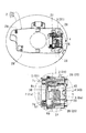
- the housing 1 has a flange portion 11 protruding to the upper and inner periphery of the cylindrical portion 10.
- the cylindrical portion 10 includes a through-hole 13 provided in the bottom wall, a recess 14 provided in the inner periphery and capable of receiving the base 3, and a recess formed by lowering the upper left and right sides of the recess 14. 15, a recessed portion 16 formed at a lower position in the inner periphery and facing the concave portion 14, a lock means 18 assembled to the outer periphery and locking the lid 2 in the closed position, and the lid 2 slightly from the closed position. And a push lifter 17 for lifting.
- the flange portion 11 is provided with a plurality of protrusions 12a and arc-shaped ribs 12b for receiving the lid 2 as shown in FIG.
- a connecting pipe extending to the fuel tank (not shown) is connected to the through hole 13.
- the fueling fuel nozzle is refueled in a state where the fueling nozzle is inserted into the through hole 13 and the connecting pipe from the fueling port that is the upper opening of the cylindrical part 10.
- the concave portion 14 is communicated with the concave portion 15 on the upper side, and is provided on the opposing inner side surfaces and extends vertically, and the projecting portion 14a that protrudes from the upper side and the clamping projection that projects the rear side to position the base 3 14b, and an attachment hole 14c provided between the inner surface and the clamping protrusion 14b and penetrating outward.
- the hollow portion 15 is a place where the base end side of the lid 2 escapes when the lid 2 is rotated to the fully open position as inferred from FIG.
- the recess 16 is provided with a through-hole 16a for projecting the push 17a of the push lifter 17 from the outside to the inside.
- the push lifter 17 is disclosed in Japanese Patent Application Laid-Open No. 2015-105062. When the lid 2 is opened, the push 17a is protruded, the lid 2 is pushed up a little and lifted, and the lid tip side is grasped with a finger or the like. To be able to.
- a through hole (not shown) through which the lock member 18a of the lock means 18 protrudes from the outside to the inside is provided near the recess 16.
- the lock means 18 is mounted on the outer periphery of the housing 1 and can lock the lid 2 in a closed state when the lock member 18a protrudes from the through hole, and can switch the lid 2 to an open state when the lock member 18 sinks from the through hole. It becomes.
- the housing 1 is held with respect to the mounting frame 9 mounted inside the opening of the outer panel 8 of the vehicle body with the lid 2 assembled as shown in FIG.
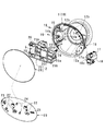
- the lid 2 includes a lid 20 and a support 25.
- the lid 20 has a disk shape that fits in the opening of the outer panel 8 as shown in FIG.
- a plurality of positioning projections 21, 24, coupling engaging pieces 22, 23, and the like are provided on the back surface of the lid 20.
- the support body 25 is formed on the pair of arm portions 26 on the rear side. Each arm portion 26 is slightly thicker in the vertical direction as it goes from the front-rear middle to the end side.
- a shaft hole 26a and a shaft hole 26b are provided in the front and rear of the opposing inner surface of each arm portion 26 and are provided on the same coaxial line.
- a recess 25 a for positioning the protrusion 21 an engaged portion 25 b that engages with each engaging piece 22, and an engaged portion that engages with each engaging piece 23 25d, ribs 25c for positioning the protrusions 24, and the like are provided.
- the support body 25 is formed of a protrusion 21 and a recess 25a, each engagement piece 22 and an engaged portion 25b, each engagement piece 23 and an engaged portion 25d, and each protrusion 24 and a rib 25c. Mounted by engagement.
- the engagement piece 28 has a locking hole 28a penetrating in the front-rear direction, and the lock member 18a is engaged with the locking hole 28a to lock the lid 2 in the closed position.
- the regulating piece 29 regulates inadvertent swinging of the lid 2 by contacting the corresponding inner surface of the housing 1 at the closed position of the lid 2.
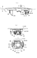
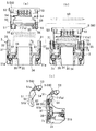
- the base 3 has a block shape that fits in the recess 14 and has a rear wall 30 that forms a design surface as shown in FIGS. 8 to 10C and side walls 31 and 31 connected to both sides of the rear wall 30. And both side walls 31 located on the upper side of the rear wall 30 and inner side walls 33, 33 projecting at an interval 32.
- the both side walls 31 are the highest on the rear wall 30 side, the front side disposed in the back of the recess 14 is low, and the vertical groove 37 provided at the raised portion on the rear wall 30 side, and the upper side of the vertical groove 37 And a through hole 35 for inserting and supporting the shaft 59, a mounting hole 31a provided on the front end face, and the like.
- Both inner side walls 33 have a shaft hole 36 penetrating on the coaxial line, and a wall portion 34 extending downward with a space from the side wall 31.
- One of the wall portions 34 extends long to the same position as the lower surface of the side wall 31, but the other is cut short.
- One wall portion 34 is provided with a fitting hole 38 for fitting the other end 6 c of the first spring body 6.
- a fitting hole 39 penetrating in the vertical direction for fitting the other end 7 c of the second spring body 7 is provided at a location close to the rear wall 30. (See FIGS. 10A to 10C).
- the above base 3 is pushed into the recess 14 so that the groove portions 37 on both sides fit into the protrusions 14a. Then, the base 3 is positioned in a state where the front lower corner portion of each side wall 31 is sandwiched between the inner surface of the recess and the restricting projection 14b, and is attached to the recess 14 by the engagement of the protrusion 14a and the groove 37. Is done. Thereafter, the base 3 is designed not to be inadvertently detached from the recess 4 by screwing a stopper 19 such as a set screw from the outside of the housing 1 into the attachment hole 31a through the attachment hole 14c. However, such a stopper 19 may be omitted.
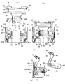
- the first link 4 and the second link 5 support the lid 2 or the support 24 so as to be rotatable with respect to the base 3.
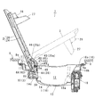
- the first link 4 is connected to the substantially rectangular upper plate part 40 and the lower side of the upper plate part 40 as shown in FIG. 8 and FIGS.
- a narrow middle plate portion 41 and an arm portion 42 connected to the middle plate portion 41 and extending substantially horizontally are provided.
- the upper plate portion 40 is provided with a shaft portion 43 protruding on the same axis on both side surfaces and a small protrusion 47 protruding below the shaft portion 43.
- the middle plate portion 40 is provided with a shaft portion 44 protruding on the same axis on both lower side surfaces.
- the arm portion 42 extends substantially at right angles from one side of the middle plate portion 40, and has a hook-like portion 45 provided on the inner surface side, and a fitting hole 46 penetrating in the distal end width direction.
- the first link 4 described above is rotatably supported by the base 3 by fitting both shaft portions 44 into corresponding shaft holes 36 on the base side.
- the first spring body 6 is assembled between the first link 4 and the base 3.
- the first spring body 6 is a coil spring, and one end 6b of the winding portion 6a is restricted from fitting in the fitting hole 46 on the arm portion side, and the other end 6c of the winding portion 6a expresses a biasing force.
- the fitting is restricted in the fitting hole 38 on the base side.
- each shaft portion 43 on the upper side with respect to the support 25 is fitted and connected to the shaft hole 26a so as to be rotatable.
- the small protrusion 47 reduces frictional resistance by, for example, slidably contacting the opposing portion of the base 3 in the process in which the first link 4 rotates around the shaft portion 44 fitted in the base-side shaft hole 36. Makes it easy to absorb rattling.
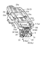
- the second link 5 protrudes from the plate body 50 having a substantially rectangular shape in a side view and a predetermined distance below the plate body 50. And a pair of legs 51.
- the plate body 50 has a flat surface (design surface) formed on the outer side of the lid 2 at the fully open position of the lid 2, and a large number of inner surfaces on the opposite side on the upper side.
- a rib is provided and a cavity is formed on the lower side. In the cavity, shaft portions 54 for holding the springs are provided on both inner side surfaces so as to protrude on the coaxial line.
- the plate body 50 is provided with shaft portions 53, 53 protruding on the coaxial line on both upper side surfaces, a shaft hole 55 penetrating on the coaxial line on both lower sides, and the back side of each leg portion. And a longitudinal groove 56. Further, the outer surfaces of the plate body 50 and the leg portion 51 are formed to be flush with each other, and include a small protrusion 51 a provided in a portion between the shaft portion 53 and the shaft hole 55, and a portion including the periphery of the shaft hole 55. And a small protrusion 51b.
- Each of the small protrusions 51a and 51b is in a process of rotating with the shaft 59 inserted into the base-side shaft hole 55 from the shaft hole 55 as a fulcrum, for example, by sliding the small link 51a, 51b against the opposing portion of the base 3 To make it easier to absorb rattling.
- the lower side of the plate body 50 and the leg portions 51 are disposed between the side walls 31 with respect to the base 3, and the respective shaft holes 55 are disposed so as to overlap the corresponding shaft holes 35. .
- the shaft 59 is inserted into the shaft hole 35 and the shaft hole 55 on one side and the shaft hole 55 and the shaft hole 35 on the other side as shown in FIG. 59 is supported rotatably with 59 as a fulcrum.
- the second spring body 7 is assembled between the second link 5 and the base 3.
- the second spring body 7 is a coil spring, and in a state in which the winding portion 7a is fitted and held on the shaft portions 54 on both sides, the one end 7b of the winding portion is fitted to the groove portion 56 of one leg portion.
- the other end 7c of the winding portion is regulated to be fitted into the base-side fitting hole 39 while exerting an urging force.
- both shaft portions 53 are fitted and connected to the support body 25 so as to be rotatable in corresponding shaft holes 26b of the support body.
- the lid biasing structure (reference numeral A in FIG. 13) according to the above-described invention is urged in the closing direction so that the lid 2 does not rattle at the closed position where the upper opening of the housing 1 is blocked. In this state, it is locked by the locking means 18.
- the lid 2 is pushed slightly in the opening direction against the urging force of the spring bodies 6 and 7 by the push 17a of the push lifter (in FIG. 13, the lid opening angle is slightly increased). About 6 degrees).
- the user picks the lid 2 with his / her hand or the like and rotates the lid 2 against the urging force in the opening direction.
- the spring stress is momentarily weakened because the lid 2 is momentarily biased in the opening direction. This is different from conventional ones.
- the lid opening angle at the fully opened position is about 118 degrees, and the urging is performed in the opening direction so as not to rattle at the fully opened position.
- the lid urging structure A is strongly urged in the lid opening direction at the fully opened position as compared with the comparative lid urging structure B using only the second spring body 6 as the urging member. Bound is reduced.
- the first position is a dead point of the first spring body 6 when the lid opening angle is 10 degrees.
- the lid opening angle is 48 degrees, which is a dead point of the second spring body 7.
- the lid opening angle at the first position is about 25 degrees due to the balance of the spring bodies 6 and 7 as compared with the comparative product B which is at the first position when the lid opening angle is about 10 degrees. It is getting bigger. For this reason, in the closing operation of the lid 2, the lid 2 is rotated in the closing direction by the urging force from the second position, then instantaneously stopped at the first position, and then again rotated in the closing direction by the urging force. In this process, if the lid opening angle at the first position is as small as about 10 degrees as in the comparative product of the bias urging structure B, it will easily hit the push lifter 16 at a high speed, making it unusable and impairing luxury. It is.
- the lid opening angle at the first position is largely corrected to about 25 degrees, such a problem can be solved or alleviated. Can be reduced, and a sense of quality is increased, which is also effective in preventing finger pinching.
- both link members 4 and 5 are similar to the two link members of Patent Document 1, and the original opening / closing locus of the first link 4 is changed by the second link 5 as the opening / closing locus of the lid 2.
- the lid 2 is controlled so as not to interfere with the outer panel 8 during opening and closing.
- the lid 2 is in the fully open position via the first and second links 4, 5 as shown in FIG. 6B, and the upper side of the first link 4 is connected to the plate body 50 of the second link 5.
- the base end side edge portion of the lid 2 is in contact with the middle plate portion 40 of the first link 4. Thereby, the lid 2 is stably held at the fully opened position opened at 118 degrees.
- the first link 4 is sandwiched between the lid 2 and the second link 5 and thus is difficult to see, and the second link 5 is located on the space side of the housing 1.
- the flat design surface is arranged, and the design surface is substantially the same surface (continuous surface) as the rear wall 30 of the base 3 integrally incorporated in the housing 1 and the corresponding portion of the lid 2. It is excellent in appearance.
- the lid biasing structure of the present invention can be variously modified except for the requirements specified in the claims.
- the housing 1 the configuration in which the fuel filler opening is arranged inside the opening is shown, but the configuration in which the electric charging port is arranged inside the opening may be used.
- the lid 2 the support body 24 is attached to the lid body 20, but a portion corresponding to the support body 24 may be formed integrally with the lid body 20.
- the base 3 for example, a base corresponding portion may be formed integrally with the housing.
- the first and second links 4 and 5 may have a structure in which one end side is pivotally supported on the back side of the lid and the other end side is pivotally supported by the housing or the base. Is not limited to this form and can be designed arbitrarily.
- Housing (10 is a cylindrical part) 2 .. lid (lids 20 and 25 are supports) 3 ....
- Base (30 is the main body, 31 is the outer wall, 33 is the inner wall) 4 ⁇ First link (link member: 40 is upper plate portion, 42 is arm portion) 5...
- Second link (link member: 50 is a plate, 51 is a leg, and 56 is a groove) 6...
- First spring body (biasing member: 6b is one end, 6c is the other end) 7...
- Outer panel 9 ...
- Lock means 34 ... Wall 36 ... Shaft hole 38 ...
Abstract
Structure de poussée de couvercle selon la présente invention comprenant : un boîtier ; un couvercle qui est supporté pivotant sur le boîtier par l'intermédiaire d'un élément de liaison et qui alterne entre une position fermée dans laquelle le couvercle ferme une ouverture dans le boîtier, une première position au milieu de l'ouverture à partir de la position fermée, une seconde position située plus loin dans une direction d'ouverture, et une position complètement ouverte ; et un élément de poussée qui pousse le couvercle dans une direction de fermeture dans la position fermée et, lorsque le couvercle est pivoté de la direction de fermeture vers la seconde position en surmontant la force de poussée et, par conséquent, la direction de poussée est inversée, permet le passage de la seconde position à la position complètement ouverte par la force de poussée. L'élément de poussée est composé d'une pluralité de ressorts disposés entre l'élément de liaison et le boîtier. La force d'actionnement pour faire pivoter le couvercle de la position fermée à la première position ou à une position proche de la première position en surmontant la force de poussée et la force de poussée qui pousse le couvercle de telle sorte que le couvercle pivote de la première position ou une position proche de la première position vers la position fermée sont ajustées au moyen de l'équilibre entre les ressorts.
Priority Applications (4)
| Application Number | Priority Date | Filing Date | Title |
|---|---|---|---|
| KR1020207034233A KR102420814B1 (ko) | 2018-06-05 | 2019-05-30 | 리드 탄지 구조 |
| DE112019001824.8T DE112019001824T5 (de) | 2018-06-05 | 2019-05-30 | Vorgespannte Deckelstruktur |
| US17/047,235 US11976501B2 (en) | 2018-06-05 | 2019-05-30 | Lid urging structure |
| CN201980028276.1A CN112088104B (zh) | 2018-06-05 | 2019-05-30 | 盖加载构造 |
Applications Claiming Priority (2)
| Application Number | Priority Date | Filing Date | Title |
|---|---|---|---|
| JP2018-107393 | 2018-06-05 | ||
| JP2018107393A JP6926031B2 (ja) | 2018-06-05 | 2018-06-05 | リッド付勢構造 |
Publications (1)
| Publication Number | Publication Date |
|---|---|
| WO2019235352A1 true WO2019235352A1 (fr) | 2019-12-12 |
Family
ID=68770307
Family Applications (1)
| Application Number | Title | Priority Date | Filing Date |
|---|---|---|---|
| PCT/JP2019/021526 WO2019235352A1 (fr) | 2018-06-05 | 2019-05-30 | Structure de poussée de couvercle |
Country Status (6)
| Country | Link |
|---|---|
| US (1) | US11976501B2 (fr) |
| JP (1) | JP6926031B2 (fr) |
| KR (1) | KR102420814B1 (fr) |
| CN (1) | CN112088104B (fr) |
| DE (1) | DE112019001824T5 (fr) |
| WO (1) | WO2019235352A1 (fr) |
Families Citing this family (2)
| Publication number | Priority date | Publication date | Assignee | Title |
|---|---|---|---|---|
| DE102018125209A1 (de) * | 2018-10-11 | 2020-04-16 | Bayerische Motoren Werke Aktiengesellschaft | Tank- oder Ladeklappenanordnung |
| DE102021112936A1 (de) * | 2021-05-19 | 2022-11-24 | Lisa Dräxlmaier GmbH | VORRICHTUNG ZUM ÖFFNEN UND VERSCHLIEßEN EINER LADEDOSE |
Citations (4)
| Publication number | Priority date | Publication date | Assignee | Title |
|---|---|---|---|---|
| JP2005343367A (ja) * | 2004-06-04 | 2005-12-15 | Nissan Motor Co Ltd | フューエルリッドの取付構造 |
| JP2014121985A (ja) * | 2012-12-21 | 2014-07-03 | Mitsubishi Motors Corp | リッド装置 |
| JP2017047827A (ja) * | 2015-09-03 | 2017-03-09 | 株式会社ニフコ | 車両のリッド装置 |
| JP2018047717A (ja) * | 2016-09-20 | 2018-03-29 | トヨタ自動車株式会社 | 蓋開閉構造 |
Family Cites Families (6)
| Publication number | Priority date | Publication date | Assignee | Title |
|---|---|---|---|---|
| JP2001065215A (ja) * | 1999-08-31 | 2001-03-13 | Jidosha Denki Kogyo Co Ltd | フューエルフィラーリッドオープナーアクチュエータ |
| EP1314605B1 (fr) * | 2001-11-26 | 2005-01-26 | Toyoda Gosei Co., Ltd. | Dispositif capuchon |
| JP3952289B2 (ja) * | 2002-09-04 | 2007-08-01 | 株式会社ニフコ | 蓋体のロック機構及び開閉装置 |
| FR2845645B1 (fr) * | 2002-10-14 | 2004-12-03 | Neyr Plastiques Holding | Trappe a carburant |
| JP3959074B2 (ja) * | 2004-05-11 | 2007-08-15 | 本田技研工業株式会社 | 車両のフュエルフィラーリッド構造 |
| JP6180992B2 (ja) * | 2014-04-25 | 2017-08-16 | 株式会社ニフコ | リッド装置 |
-
2018
- 2018-06-05 JP JP2018107393A patent/JP6926031B2/ja active Active
-
2019
- 2019-05-30 DE DE112019001824.8T patent/DE112019001824T5/de active Pending
- 2019-05-30 CN CN201980028276.1A patent/CN112088104B/zh active Active
- 2019-05-30 WO PCT/JP2019/021526 patent/WO2019235352A1/fr active Application Filing
- 2019-05-30 US US17/047,235 patent/US11976501B2/en active Active
- 2019-05-30 KR KR1020207034233A patent/KR102420814B1/ko active IP Right Grant
Patent Citations (4)
| Publication number | Priority date | Publication date | Assignee | Title |
|---|---|---|---|---|
| JP2005343367A (ja) * | 2004-06-04 | 2005-12-15 | Nissan Motor Co Ltd | フューエルリッドの取付構造 |
| JP2014121985A (ja) * | 2012-12-21 | 2014-07-03 | Mitsubishi Motors Corp | リッド装置 |
| JP2017047827A (ja) * | 2015-09-03 | 2017-03-09 | 株式会社ニフコ | 車両のリッド装置 |
| JP2018047717A (ja) * | 2016-09-20 | 2018-03-29 | トヨタ自動車株式会社 | 蓋開閉構造 |
Also Published As
| Publication number | Publication date |
|---|---|
| KR102420814B1 (ko) | 2022-07-13 |
| US20210164272A1 (en) | 2021-06-03 |
| JP6926031B2 (ja) | 2021-08-25 |
| CN112088104A (zh) | 2020-12-15 |
| US11976501B2 (en) | 2024-05-07 |
| JP2019209834A (ja) | 2019-12-12 |
| CN112088104B (zh) | 2024-02-09 |
| DE112019001824T5 (de) | 2020-12-24 |
| KR20210003235A (ko) | 2021-01-11 |
Similar Documents
| Publication | Publication Date | Title |
|---|---|---|
| WO2017038833A1 (fr) | Dispositif de capot de véhicule | |
| JP5950382B2 (ja) | ドアハンドル装置 | |
| WO2019235352A1 (fr) | Structure de poussée de couvercle | |
| WO2018216564A1 (fr) | Dispositif pour portes | |
| JP2003205956A (ja) | 蓋用開放装置 | |
| WO2006085461A1 (fr) | Dispositif d'ouverture et de fermeture de porte | |
| JP6709760B2 (ja) | 車両のリッド装置 | |
| JP5755041B2 (ja) | 蓋開閉機構及び収納装置 | |
| JP6709827B2 (ja) | 車両のリッド装置 | |
| JP2019209834A5 (fr) | ||
| JP5756360B2 (ja) | ロック装置 | |
| KR101866305B1 (ko) | 차량용 콘솔 암레스트의 힌지 유닛 | |
| JP6708094B2 (ja) | フィラーリッド構造体 | |
| KR20090093811A (ko) | 좌우 여닫이식 덮개의 연동기구 | |
| JP5613479B2 (ja) | 給油口フラップ開閉装置 | |
| JP7368153B2 (ja) | フラップ開閉機構 | |
| JP5224290B2 (ja) | 扉のハンドル装置 | |
| JP3533954B2 (ja) | 車両用グローブボックス構造 | |
| KR20190016732A (ko) | 콘솔 암레스트의 힌지 구조 | |
| JP4147346B2 (ja) | 可動体の開閉装置 | |
| JP2752052B2 (ja) | 開閉扉用ロック装置及び被係止具 | |
| JP3732208B1 (ja) | 扉開閉機構 | |
| JP2014065397A (ja) | 収容構造体装置 | |
| JP5633333B2 (ja) | 車両用ドアインサイドハンドル | |
| JP5544543B2 (ja) | 扉のハンドル装置 |
Legal Events
| Date | Code | Title | Description |
|---|---|---|---|
| 121 | Ep: the epo has been informed by wipo that ep was designated in this application |
Ref document number: 19815417 Country of ref document: EP Kind code of ref document: A1 |
|
| ENP | Entry into the national phase |
Ref document number: 20207034233 Country of ref document: KR Kind code of ref document: A |
|
| 122 | Ep: pct application non-entry in european phase |
Ref document number: 19815417 Country of ref document: EP Kind code of ref document: A1 |