WO2019225458A1 - 端子付き電線 - Google Patents
端子付き電線 Download PDFInfo
- Publication number
- WO2019225458A1 WO2019225458A1 PCT/JP2019/019451 JP2019019451W WO2019225458A1 WO 2019225458 A1 WO2019225458 A1 WO 2019225458A1 JP 2019019451 W JP2019019451 W JP 2019019451W WO 2019225458 A1 WO2019225458 A1 WO 2019225458A1
- Authority
- WO
- WIPO (PCT)
- Prior art keywords
- pair
- single core
- core wire
- wire
- barrel
- Prior art date
- Legal status (The legal status is an assumption and is not a legal conclusion. Google has not performed a legal analysis and makes no representation as to the accuracy of the status listed.)
- Ceased
Links
Images

Classifications
-
- H—ELECTRICITY
- H01—ELECTRIC ELEMENTS
- H01R—ELECTRICALLY-CONDUCTIVE CONNECTIONS; STRUCTURAL ASSOCIATIONS OF A PLURALITY OF MUTUALLY-INSULATED ELECTRICAL CONNECTING ELEMENTS; COUPLING DEVICES; CURRENT COLLECTORS
- H01R4/00—Electrically-conductive connections between two or more conductive members in direct contact, i.e. touching one another; Means for effecting or maintaining such contact; Electrically-conductive connections having two or more spaced connecting locations for conductors and using contact members penetrating insulation
- H01R4/10—Electrically-conductive connections between two or more conductive members in direct contact, i.e. touching one another; Means for effecting or maintaining such contact; Electrically-conductive connections having two or more spaced connecting locations for conductors and using contact members penetrating insulation effected solely by twisting, wrapping, bending, crimping, or other permanent deformation
- H01R4/18—Electrically-conductive connections between two or more conductive members in direct contact, i.e. touching one another; Means for effecting or maintaining such contact; Electrically-conductive connections having two or more spaced connecting locations for conductors and using contact members penetrating insulation effected solely by twisting, wrapping, bending, crimping, or other permanent deformation by crimping
- H01R4/183—Electrically-conductive connections between two or more conductive members in direct contact, i.e. touching one another; Means for effecting or maintaining such contact; Electrically-conductive connections having two or more spaced connecting locations for conductors and using contact members penetrating insulation effected solely by twisting, wrapping, bending, crimping, or other permanent deformation by crimping for cylindrical elongated bodies, e.g. cables having circular cross-section
- H01R4/184—Electrically-conductive connections between two or more conductive members in direct contact, i.e. touching one another; Means for effecting or maintaining such contact; Electrically-conductive connections having two or more spaced connecting locations for conductors and using contact members penetrating insulation effected solely by twisting, wrapping, bending, crimping, or other permanent deformation by crimping for cylindrical elongated bodies, e.g. cables having circular cross-section comprising a U-shaped wire-receiving portion
- H01R4/185—Electrically-conductive connections between two or more conductive members in direct contact, i.e. touching one another; Means for effecting or maintaining such contact; Electrically-conductive connections having two or more spaced connecting locations for conductors and using contact members penetrating insulation effected solely by twisting, wrapping, bending, crimping, or other permanent deformation by crimping for cylindrical elongated bodies, e.g. cables having circular cross-section comprising a U-shaped wire-receiving portion combined with a U-shaped insulation-receiving portion
-
- H—ELECTRICITY
- H01—ELECTRIC ELEMENTS
- H01R—ELECTRICALLY-CONDUCTIVE CONNECTIONS; STRUCTURAL ASSOCIATIONS OF A PLURALITY OF MUTUALLY-INSULATED ELECTRICAL CONNECTING ELEMENTS; COUPLING DEVICES; CURRENT COLLECTORS
- H01R13/00—Details of coupling devices of the kinds covered by groups H01R12/70 or H01R24/00 - H01R33/00
- H01R13/02—Contact members
- H01R13/10—Sockets for co-operation with pins or blades
- H01R13/11—Resilient sockets
- H01R13/114—Resilient sockets co-operating with pins or blades having a square transverse section
-
- H—ELECTRICITY
- H01—ELECTRIC ELEMENTS
- H01R—ELECTRICALLY-CONDUCTIVE CONNECTIONS; STRUCTURAL ASSOCIATIONS OF A PLURALITY OF MUTUALLY-INSULATED ELECTRICAL CONNECTING ELEMENTS; COUPLING DEVICES; CURRENT COLLECTORS
- H01R43/00—Apparatus or processes specially adapted for manufacturing, assembling, maintaining, or repairing of line connectors or current collectors or for joining electric conductors
- H01R43/04—Apparatus or processes specially adapted for manufacturing, assembling, maintaining, or repairing of line connectors or current collectors or for joining electric conductors for forming connections by deformation, e.g. crimping tool
- H01R43/048—Crimping apparatus or processes
Definitions
- the technology disclosed in this specification relates to an electric wire with a terminal in which a terminal is crimped to a single core wire.
- the female terminal includes a wire barrel that is crimped to a core wire made of a plurality of metal wires, and an insulation barrel that is crimped to an insulating coating that covers the outer periphery of the core wire.
- the tip of the wire barrel enters between the plurality of metal wires in a state where the wire barrel is crimped to the core wire.
- the contact surface where a pair of wire barrels mutually contact is formed in the part near the front-end
- the frictional force generated on the contact surface prevents the pair of wire barrels from opening. This is particularly effective when expansion at a high temperature and contraction at a low temperature are repeated as in a place where the temperature change is relatively large.
- the tip of the wire barrel is less likely to enter the single core wire. This is because, unlike the case where the core wire is composed of a plurality of metal strands, the single core wire has no gap into which the tip of the wire barrel enters. For this reason, a contact surface where the pair of wire barrels are in contact with each other is not formed in the portion near the tip of the pair of wire barrels, or even if a contact surface is formed, a sufficient frictional force is generated. May not have the area.
- the pair of wire barrels when used in a place where the temperature change is relatively large, at a high temperature, the pair of wire barrels expand in a direction in which they approach each other. On the other hand, at a low temperature, the pair of wire barrels contract in a direction away from each other. Then, since the contact surface is not originally formed or does not have a sufficient area even when the contact surface is formed, the pair of wire barrels has a form in which the pair of wire barrels are crimped to the single core wire by friction force. There is a risk that it cannot be held. As a result, there is a problem that the contact pressure between the single core wire and the wire barrel is reduced, and the contact resistance is increased.
- the technology disclosed in this specification has been completed based on the above-described circumstances, and an object thereof is to provide a terminal that suppresses a decrease in contact pressure between a single core wire and a wire barrel.
- the electric wire with a terminal disclosed in the present specification is an electric wire with a terminal including a metal single core wire and a terminal to be crimped to the single core wire, and the single core wire is placed on the terminal. And a pair of barrel portions that protrude upward from both side edges of the bottom plate portion and are crimped to the single core wire, the pair of barrel portions from both side edges of the bottom plate portion. A pair of side wall portions protruding upward, and a pair of folded pieces folded downward from the upper ends of the pair of side wall portions, each of the pair of folded pieces contacting the single core wire from above. A first contact portion; a second contact portion where the pair of folded pieces contact each other at a position above the first contact portion; and a third contact portion which contacts the inner surfaces of the pair of side wall portions. ing.
- the shape in which the pair of barrel portions are pressure-bonded to the single core wire can be maintained by the frictional force generated at the second contact portion. Further, since the pair of barrel portions has a pair of side wall portions protruding upward and a pair of folded pieces folded downward, the direction of expansion or contraction of the pair of barrel portions due to temperature change is the vertical direction. It has become. For this reason, even if there exists a temperature change, it is suppressed that a pair of barrel parts expand or contract in the direction which approaches or spaces apart.
- the pair of barrel portions are prevented from expanding or contracting in the direction in which the area of the second contact portion is reduced, so that the shape in which the pair of barrel portions are crimped to the single core wire can be maintained.
- the pair of folded pieces and the pair of side wall portions are in contact with each other at the third contact portion, the pair of folded pieces and the pair of side wall portions are heated by the frictional force generated at the third contact portion. Expansion or contraction due to the change is suppressed. Thereby, a shape by which a pair of barrel part was crimped
- the shape in which the pair of barrel portions are crimped to the single core wire can be maintained, so that the contact pressure of the barrel portion to the single core wire is maintained, and the contact resistance between the barrel portion and the single core wire is increased. Can be suppressed.
- the width dimension W of the bottom plate part in a direction orthogonal to the axial direction of the single core wire placed on the bottom plate part is set to be four times the thickness dimension T of the pair of side wall parts. Also good.
- the up-down direction which comprises a barrel part in the range of the width dimension W of a bottom-plate part is crimped
- a maximum of four metal plates having a thickness dimension T extending in the width direction are arranged in the width direction.
- the width dimension W of the bottom plate portion in a direction orthogonal to the axial direction of the single core wire placed on the bottom plate portion is the same as the thickness dimension T of the pair of side wall portions, which is 6 times greater, Or it is good also as a structure set small.
- the pair of folded pieces are folded back upward from lower ends of the pair of first folded pieces, and a pair of first folded pieces folded downward from the upper ends of the pair of side wall parts. It is good also as a structure provided with a pair of 2nd folding piece located between a part and said pair of 1st folding piece.
- the width dimension W of a baseplate part is within the range, a maximum of six metal plates having a thickness dimension T extending in the vertical direction constituting the barrel portion are arranged in the width direction. Accordingly, the pair of side wall portions, the pair of first folded pieces, and the pair of second folded pieces are compressed with a strong force in a direction orthogonal to the axial direction of the single core wire placed on the bottom plate portion, and the second The frictional force generated at the contact portion and the third contact portion can be increased. As a result, since the pair of barrel portions can hold the shape crimped to the single core wire, the contact pressure of the barrel portion to the single core wire is maintained, and the contact resistance between the barrel portion and the single core wire is increased. Can be suppressed.
- the terminal-attached electric wire disclosed in the present specification, it is possible to suppress a decrease in contact pressure between the single core wire and the barrel portion.
- the electric wire 10 with a terminal of this embodiment is provided with the single core electric wire 12 and the terminal 14 crimped
- the single-core electric wire 12 includes a single-core wire 16 made of a copper alloy and an insulating coating portion 18 that covers the single-core wire 16. Exposed.
- the single core wire 16 is a core wire having a very small diameter (for example, a cross-sectional area of about 0.05 square millimeters).
- the terminal 14 is a female terminal, which is formed by pressing and bending a copper alloy sheet metal, and is a box-like shape into which a mating male terminal (not shown) is fitted.
- a connecting portion 26 that connects the two.
- the crimping portion 23 protrudes upward from both end edges of the bottom plate portion 22, and is disposed behind the pair of wire barrel portions (barrel portions) 24 to which the distal end portion of the single core wire 16 is crimped, and the wire barrel portion 24, and is covered with insulation. It is comprised from a pair of insulation barrel part 25 with which the part 18 is crimped
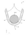
- the pair of wire barrel portions 24 is an open barrel type, and includes a pair of side wall portions 28 protruding upward from both side edges of the bottom plate portion 22 as shown in FIG.
- the pair of side wall portions 28 are folded downward from the upper ends by a crimping machine, and the pair of folded pieces formed thereby.
- the single core wire 16 is pressed by 30 from above.
- the pair of side wall portions 28 are displaced inward by a crimping machine, and the single core wire 16 is pressed from both sides by the pair of side wall portions 28.
- the ratio S2 / S1 between the cross-sectional area S1 of the single core wire 16 before crimping and the cross-sectional area S2 of the single core wire 16 after compression is about 0.8 to 0.9.
- the tip edges 32 of the pair of folded pieces 30 are in contact with the single core wire 16 from above and serve as the first contact portion 34.
- the mutually opposing surfaces of the pair of folded pieces 30 are in contact with each other and serve as the second contact portion 36.
- the second contact portion 36 is also formed to extend in the vertical direction.
- the surface of the pair of folded pieces 30 on the side opposite to the surface on the second contact portion 36 side is in contact with the inner surface of the opposing side wall portion 28 to form a third contact portion 38.
- the third contact portion 38 is located closer to the distal end portions of the pair of folded pieces 30 (that is, closer to the distal edge 32 of the pair of folded pieces 30).
- the pair of folded pieces 30 are accommodated between the pair of side wall portions 28, and the width dimension W1 in the left-right direction of the bottom plate portion 22 is a pair. It is about 4 times the thickness dimension T1 of the side wall part 28 of this.
- the width of the terminal 14 is increased. An increase in the dimension in the direction is suppressed.
- the terminal-attached electric wire 10 When the terminal-attached electric wire 10 is placed in a high temperature environment, the single core wire 16 is thermally expanded, and thereby the pair of wire barrel portions 24 are pushed upward. However, the folded pieces 30 of the pair of wire barrel portions 24 are in contact with each other by the second contact portion 36, and the pair of folded pieces 30 are respectively connected to the pair of side wall portions 28 by the third contact portion 38. In contact. For this reason, the upward displacement of the pair of wire barrel portions 24 is suppressed by the frictional force generated in the second contact portion 36 and the third contact portion 38.
- the second contact portion 36 is formed long in the vertical direction as described above, the friction generated in the second contact portion 36 as compared with the conventional configuration in which only the tip end portion of the barrel contacts.
- the power is growing.
- the pair of wire barrel portions 24 is suppressed from being pushed up due to the thermal expansion of the single core wire 16.
- the thermally expanded single core wire 16 contracts and the pair of wire barrel portions 24 tends to be displaced downward, but in the second contact portion 36 and the third contact portion 38.
- the downward displacement of the pair of wire barrel portions 24 is restricted by the generated frictional force.
- the direction in which the pair of wire barrel portions 24 are displaced is the vertical direction. It is suppressed that 24 expand
- a pair of wire barrel portions (barrel portions) are generated by the frictional force generated at the second contact portion 36.
- 24 can hold the shape crimped to the single core wire 16.
- a pair of wire barrel part (barrel part) 24 has a pair of side wall part 28 which protrudes upwards, and a pair of folding
- the direction of expansion or contraction due to the temperature change is the vertical direction.
- the portion 28 is prevented from expanding or contracting due to a temperature change. Thereby, a pair of wire barrel parts (barrel part) 24 can hold
- FIG. As described above, since the pair of wire barrel portions (barrel portions) 24 can hold the shape crimped to the single core wire 16, the contact pressure of the wire barrel portions (barrel portions) 24 to the single core wire 16 is maintained. An increase in contact resistance between the wire barrel portion (barrel portion) 24 and the single core wire 16 can be suppressed.
- the wire barrel portion (barrel portion) 24 is within the range of the width dimension W ⁇ b> 1 of the bottom plate portion 22 by being crimped to the single core wire 16 so that the pair of folded pieces 30 are accommodated between the pair of side wall portions 28.
- a maximum of four metal plates having a thickness dimension T1 extending in the vertical direction are arranged in the width direction.
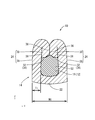
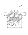
- the terminal-attached electric wire 10A of the present embodiment will be described with reference to FIG.
- the single core wire 16 when the single core wire 16 is crimped to the pair of wire barrel portions 24, the pair of side wall portions 28 are configured to bend down once.
- the single core wire 16 is a pair of wires.
- the pair of side wall portions 28A When pressure-bonded to the barrel portion 24A, the pair of side wall portions 28A is folded once downward, and further, the tip thereof is folded once upward.
- Other configurations are the same as those of the first embodiment.
- the pair of side wall portions 28A are folded downward from the upper end, thereby forming the pair of first folded pieces 40. Further, when the tips of the pair of first folded pieces 40 are pressed against the single core wire 16, the tips of the pair of first folded pieces 40 do not enter the single core wire, and the tips of the pair of first folded pieces 40 are single core wire.
- the front ends of the pair of first folded pieces 40 are folded upward by the reaction force when pressed against 16, thereby forming a pair of second folded pieces 42.
- the pair of second folded pieces 42 are folded upward via a pair of folded base end portions 44 connected to the lower ends of the pair of first folded pieces 40, and the pair of side wall portions 28 and the pair of first folded pieces. 40.
- the folded base end portions 44 of the pair of second folded pieces 42 are the first contact portions 34A that contact the single core wire 16 from above. Moreover, the mutually opposing surface of a pair of 1st folding
- the third contact portion 38 ⁇ / b> A is located near the tip of the second folded piece 42 (that is, the upper end side of the pair of second folded pieces 42).
- a portion of the pair of second folded pieces 42 that contacts the pair of first folded pieces 40 is a fourth contact portion 46.
- the pair of first folded pieces 40 and the pair of second folded pieces 42 are accommodated between the pair of side wall portions 28A, and the bottom plate portion 22A.
- the width dimension W2 in the left-right direction is about six times the thickness dimension T2 of the pair of side wall portions 28A. In this way, the pair of side wall portions 28, the two first folded pieces 40, and the two second folded pieces 42 are pressure-bonded so as to be aligned within the range of the width dimension W2 of the bottom plate portion 22A.
- the pair of side wall portions 28, the pair of first folded pieces 40, and the pair of second folded pieces 42 are compressed with a strong force, and the frictional force generated in the second contact portion 36A and the third contact portion 38A.
- the pair of wire barrel portions 24 ⁇ / b> A can hold the shape crimped to the single core wire 16, so that the contact pressure of the wire barrel portion 24 to the single core wire 16 is maintained, and the wire barrel portion 24 and the single core wire 16 are maintained. The increase in contact resistance between the two can be suppressed.
- the pair of first folded pieces 40 and the pair of second folded pieces 42 are crimped to the single core wire 16 between the pair of side wall portions 28.
- the width dimension W2 of the bottom plate portion 22 up to six metal plates having a thickness T2 extending in the vertical direction constituting the barrel portion are arranged in the width direction.
- the terminal 14 is a female terminal, but may be applied to a male terminal.
- the single core wire 16 has a very thin diameter, but may be applied to a general diameter (for example, a cross-sectional area of about 0.5 parallel millimeters).
- the single-core electric wire 12 has the insulating coating portion 18, but may be a bare electric wire that does not have the insulating coating portion 18.
- Terminal 16 Single core wire 22, 22A: Bottom plate portion 24, 24A: Wire barrel portion (barrel portion) 28, 28A: Side wall portion 30: Folded piece 32: Tip edge 34, 34A: First contact portion 36, 36A: Second contact portion 38, 38A: Third contact portion 40: First folded piece 42: Second folded piece 44: Folded base end W1: Width dimension T1: Thickness dimension W2: Width dimension T2: Thickness dimension
Landscapes
- Engineering & Computer Science (AREA)
- Manufacturing & Machinery (AREA)
- Connections Effected By Soldering, Adhesion, Or Permanent Deformation (AREA)
Priority Applications (2)
| Application Number | Priority Date | Filing Date | Title |
|---|---|---|---|
| CN201980033860.6A CN112154572A (zh) | 2018-05-23 | 2019-05-16 | 带端子电线 |
| US17/054,223 US20210159613A1 (en) | 2018-05-23 | 2019-05-16 | Wire with terminal |
Applications Claiming Priority (2)
| Application Number | Priority Date | Filing Date | Title |
|---|---|---|---|
| JP2018098480A JP2019204653A (ja) | 2018-05-23 | 2018-05-23 | 端子付き電線 |
| JP2018-098480 | 2018-05-23 |
Publications (1)
| Publication Number | Publication Date |
|---|---|
| WO2019225458A1 true WO2019225458A1 (ja) | 2019-11-28 |
Family
ID=68616668
Family Applications (1)
| Application Number | Title | Priority Date | Filing Date |
|---|---|---|---|
| PCT/JP2019/019451 Ceased WO2019225458A1 (ja) | 2018-05-23 | 2019-05-16 | 端子付き電線 |
Country Status (4)
| Country | Link |
|---|---|
| US (1) | US20210159613A1 (enExample) |
| JP (1) | JP2019204653A (enExample) |
| CN (1) | CN112154572A (enExample) |
| WO (1) | WO2019225458A1 (enExample) |
Cited By (1)
| Publication number | Priority date | Publication date | Assignee | Title |
|---|---|---|---|---|
| JP2021132021A (ja) * | 2020-02-21 | 2021-09-09 | 株式会社デルタプラス | 圧着接続端子 |
Families Citing this family (2)
| Publication number | Priority date | Publication date | Assignee | Title |
|---|---|---|---|---|
| JP2024016973A (ja) * | 2022-07-27 | 2024-02-08 | 住友電装株式会社 | 端子金具 |
| JP7504336B1 (ja) | 2023-11-24 | 2024-06-24 | ユニオンマシナリ株式会社 | 接続端子による導体圧着構造 |
Citations (2)
| Publication number | Priority date | Publication date | Assignee | Title |
|---|---|---|---|---|
| JPS55166074U (enExample) * | 1980-05-19 | 1980-11-29 | ||
| DE202015008963U1 (de) * | 2014-12-04 | 2016-04-28 | Gebauer & Griller Kabelwerke Ges.M.B.H. | Kabel-Kontaktstück-System zur elektrischen Verbindung eines Kabels mit einem Kontaktstück |
Family Cites Families (17)
| Publication number | Priority date | Publication date | Assignee | Title |
|---|---|---|---|---|
| GB1382811A (en) * | 1971-01-11 | 1975-02-05 | Post Office | Clips |
| JPS5138085A (ja) * | 1974-09-27 | 1976-03-30 | Yazaki Corp | Tanshikanagu |
| US4142771A (en) * | 1974-10-16 | 1979-03-06 | Amp Incorporated | Crimp-type terminal |
| JPS521489A (en) * | 1975-06-24 | 1977-01-07 | Yazaki Corp | Press-attached terminal for aluminium wire |
| JPS55120080U (enExample) * | 1979-02-16 | 1980-08-25 | ||
| JP5103137B2 (ja) * | 2007-11-01 | 2012-12-19 | 株式会社オートネットワーク技術研究所 | 圧着端子、端子付電線及びその製造方法 |
| JP4922897B2 (ja) * | 2007-11-02 | 2012-04-25 | 株式会社オートネットワーク技術研究所 | 圧着端子、端子付電線及びその製造方法 |
| JP2009123622A (ja) * | 2007-11-16 | 2009-06-04 | Yazaki Corp | アルミ電線用圧着端子 |
| JP5707735B2 (ja) * | 2009-07-24 | 2015-04-30 | 住友電装株式会社 | 端子金具付き電線及び端子金具付き電線の製造方法 |
| JP5695987B2 (ja) * | 2011-07-01 | 2015-04-08 | 矢崎総業株式会社 | 単芯電線及び単芯電線の端子圧着構造 |
| JP5904355B2 (ja) * | 2011-08-02 | 2016-04-13 | 矢崎総業株式会社 | 単芯電線の端子圧着構造 |
| JP5902414B2 (ja) * | 2011-08-08 | 2016-04-13 | 矢崎総業株式会社 | 端子圧着電線の製造方法 |
| JP5682547B2 (ja) * | 2011-12-12 | 2015-03-11 | 株式会社オートネットワーク技術研究所 | 端子金具 |
| JP6225313B2 (ja) * | 2016-03-04 | 2017-11-08 | 株式会社デルタプラス | 圧着接続端子及びその製造方法 |
| JP6786312B2 (ja) * | 2016-09-05 | 2020-11-18 | 矢崎総業株式会社 | 圧着端子 |
| JP6434950B2 (ja) * | 2016-10-13 | 2018-12-05 | 矢崎総業株式会社 | 端子圧着装置 |
| CN107946782B (zh) * | 2016-10-13 | 2020-07-28 | 矢崎总业株式会社 | 带端子的电线、带端子的电线的制造方法和端子压接装置 |
-
2018
- 2018-05-23 JP JP2018098480A patent/JP2019204653A/ja active Pending
-
2019
- 2019-05-16 US US17/054,223 patent/US20210159613A1/en not_active Abandoned
- 2019-05-16 WO PCT/JP2019/019451 patent/WO2019225458A1/ja not_active Ceased
- 2019-05-16 CN CN201980033860.6A patent/CN112154572A/zh active Pending
Patent Citations (2)
| Publication number | Priority date | Publication date | Assignee | Title |
|---|---|---|---|---|
| JPS55166074U (enExample) * | 1980-05-19 | 1980-11-29 | ||
| DE202015008963U1 (de) * | 2014-12-04 | 2016-04-28 | Gebauer & Griller Kabelwerke Ges.M.B.H. | Kabel-Kontaktstück-System zur elektrischen Verbindung eines Kabels mit einem Kontaktstück |
Cited By (1)
| Publication number | Priority date | Publication date | Assignee | Title |
|---|---|---|---|---|
| JP2021132021A (ja) * | 2020-02-21 | 2021-09-09 | 株式会社デルタプラス | 圧着接続端子 |
Also Published As
| Publication number | Publication date |
|---|---|
| US20210159613A1 (en) | 2021-05-27 |
| JP2019204653A (ja) | 2019-11-28 |
| CN112154572A (zh) | 2020-12-29 |
Similar Documents
| Publication | Publication Date | Title |
|---|---|---|
| JP5815352B2 (ja) | 雌端子 | |
| JP5058082B2 (ja) | 端子金具及び端子付き電線 | |
| JPH10233251A (ja) | 一体構成の接触ばね | |
| US7458864B2 (en) | Electrical plug connector having an internal leaf spring | |
| WO2019225458A1 (ja) | 端子付き電線 | |
| JP2010040404A (ja) | 端子金具及びワイヤーハーネス | |
| CN101322288B (zh) | 阴连接器端子和阴连接器 | |
| WO2010117019A1 (ja) | 圧着端子、圧着端子の圧着構造、および圧着端子の圧着方法 | |
| WO2012018050A1 (ja) | 圧着端子 | |
| JP6799942B2 (ja) | 端子付き電線 | |
| JP5403788B2 (ja) | 圧着バレルの圧着構造、圧着端子及び圧着装置 | |
| JP2017220392A (ja) | 端子付き電線 | |
| JP5099225B2 (ja) | 端子金具及び端子金具付き電線 | |
| JP2015138585A (ja) | 端子圧着構造及び端子圧着方法 | |
| JP6074336B2 (ja) | アルミニウム電線の接続構造 | |
| WO2014073287A1 (ja) | 雄端子 | |
| JP2010010000A (ja) | 端子金具及び端子付き電線 | |
| JP2010080189A (ja) | 端子金具及び端子金具付き電線 | |
| JP2010010001A (ja) | 端子金具及び端子付き電線 | |
| JP7215933B2 (ja) | 接続端子 | |
| JP2010073442A (ja) | 端子金具および端子金具付き電線 | |
| JP5316914B2 (ja) | 端子金具及び端子付き電線 | |
| JP2019114516A (ja) | 端子付き電線 | |
| JP5650381B2 (ja) | 圧着端子 | |
| JP2017079169A (ja) | 端子付き電線の製造方法、圧着冶具、および端子付き電線 |
Legal Events
| Date | Code | Title | Description |
|---|---|---|---|
| 121 | Ep: the epo has been informed by wipo that ep was designated in this application |
Ref document number: 19808260 Country of ref document: EP Kind code of ref document: A1 |
|
| NENP | Non-entry into the national phase |
Ref country code: DE |
|
| 122 | Ep: pct application non-entry in european phase |
Ref document number: 19808260 Country of ref document: EP Kind code of ref document: A1 |