WO2019220923A1 - 冷凍サイクル装置 - Google Patents
冷凍サイクル装置 Download PDFInfo
- Publication number
- WO2019220923A1 WO2019220923A1 PCT/JP2019/017772 JP2019017772W WO2019220923A1 WO 2019220923 A1 WO2019220923 A1 WO 2019220923A1 JP 2019017772 W JP2019017772 W JP 2019017772W WO 2019220923 A1 WO2019220923 A1 WO 2019220923A1
- Authority
- WO
- WIPO (PCT)
- Prior art keywords
- refrigerant
- refrigeration cycle
- pressure
- decompression device
- compressor housing
- Prior art date
- Legal status (The legal status is an assumption and is not a legal conclusion. Google has not performed a legal analysis and makes no representation as to the accuracy of the status listed.)
- Ceased
Links
Images


Classifications
-
- F—MECHANICAL ENGINEERING; LIGHTING; HEATING; WEAPONS; BLASTING
- F25—REFRIGERATION OR COOLING; COMBINED HEATING AND REFRIGERATION SYSTEMS; HEAT PUMP SYSTEMS; MANUFACTURE OR STORAGE OF ICE; LIQUEFACTION SOLIDIFICATION OF GASES
- F25B—REFRIGERATION MACHINES, PLANTS OR SYSTEMS; COMBINED HEATING AND REFRIGERATION SYSTEMS; HEAT PUMP SYSTEMS
- F25B41/00—Fluid-circulation arrangements
- F25B41/30—Expansion means; Dispositions thereof
-
- F—MECHANICAL ENGINEERING; LIGHTING; HEATING; WEAPONS; BLASTING
- F04—POSITIVE - DISPLACEMENT MACHINES FOR LIQUIDS; PUMPS FOR LIQUIDS OR ELASTIC FLUIDS
- F04C—ROTARY-PISTON, OR OSCILLATING-PISTON, POSITIVE-DISPLACEMENT MACHINES FOR LIQUIDS; ROTARY-PISTON, OR OSCILLATING-PISTON, POSITIVE-DISPLACEMENT PUMPS
- F04C29/00—Component parts, details or accessories of pumps or pumping installations, not provided for in groups F04C18/00 - F04C28/00
- F04C29/12—Arrangements for admission or discharge of the working fluid, e.g. constructional features of the inlet or outlet
-
- F—MECHANICAL ENGINEERING; LIGHTING; HEATING; WEAPONS; BLASTING
- F25—REFRIGERATION OR COOLING; COMBINED HEATING AND REFRIGERATION SYSTEMS; HEAT PUMP SYSTEMS; MANUFACTURE OR STORAGE OF ICE; LIQUEFACTION SOLIDIFICATION OF GASES
- F25B—REFRIGERATION MACHINES, PLANTS OR SYSTEMS; COMBINED HEATING AND REFRIGERATION SYSTEMS; HEAT PUMP SYSTEMS
- F25B1/00—Compression machines, plants or systems with non-reversible cycle
-
- F—MECHANICAL ENGINEERING; LIGHTING; HEATING; WEAPONS; BLASTING
- F25—REFRIGERATION OR COOLING; COMBINED HEATING AND REFRIGERATION SYSTEMS; HEAT PUMP SYSTEMS; MANUFACTURE OR STORAGE OF ICE; LIQUEFACTION SOLIDIFICATION OF GASES
- F25B—REFRIGERATION MACHINES, PLANTS OR SYSTEMS; COMBINED HEATING AND REFRIGERATION SYSTEMS; HEAT PUMP SYSTEMS
- F25B41/00—Fluid-circulation arrangements
Definitions
- the present disclosure relates to a vapor compression refrigeration cycle apparatus.
- a refrigeration cycle including a compressor, an evaporator, a condenser, a capillary tube, and a blower are installed on a support provided inside the casing.
- a refrigeration cycle including a compressor, an evaporator, a condenser, a capillary tube, and a blower are installed on a support provided inside the casing.
- this Patent Document 1 does not describe any connection mode of the compressor, the evaporator, and the condenser in the refrigeration cycle, the compressor, the evaporator, and the condenser are each connected by a refrigerant pipe in consideration of the drawings. It is understood that it has been.
- a compressor, an evaporator, and a condenser are sequentially connected by a refrigerant pipe. It acts on the refrigerant piping which is long and difficult to ensure durability. In particular, stress due to pressure pulsation or mechanical vibration accompanying the operation of the compressor tends to concentrate on the refrigerant piping connected to the compressor. When stress acts on the refrigerant pipe connected to the compressor in this way, deterioration over time due to fatigue failure or the like is difficult to avoid, and the durability of the entire refrigeration cycle apparatus is reduced.
- An object of this indication is to provide the refrigerating-cycle apparatus which can ensure durability.
- a vapor compression refrigeration cycle apparatus includes: A compressor that compresses and discharges the refrigerant; A radiator that dissipates the refrigerant discharged from the compressor; A decompression device that decompresses the refrigerant that has passed through the radiator; An evaporator that evaporates the refrigerant decompressed by the decompression device,
- the radiator has a high-pressure introduction part for introducing the refrigerant discharged from the compressor into the inside,
- the evaporator has a low pressure outlet for leading the refrigerant that has passed through the compressor to the compressor side
- the compressor includes a compression mechanism portion that compresses the refrigerant, and a compressor housing that houses the compression mechanism portion.
- the compressor housing is provided with a refrigerant discharge portion that is directly connected so that the high-pressure introduction portion is not exposed to the outside, and a refrigerant suction portion that is directly connected so that the low-pressure outlet portion is not exposed to the outside.
- the stress caused by the pressure pulsation and mechanical vibration of the compressor is large and durable, such as the radiator and the evaporator among the cycle components. Acts directly on the equipment it has. For this reason, durability of a refrigerating cycle device can be secured compared with the conventional structure where a compressor, a radiator, and an evaporator are connected via refrigerant piping.
- the refrigerant pipe is exposed to the outside, so heat loss due to heat exchange with the surrounding environment is inevitable.
- the high pressure introduction portion of the radiator is directly connected to the refrigerant discharge portion of the compressor housing so as not to be exposed to the outside, and the low pressure outlet portion of the evaporator is not exposed to the outside. It is directly connected to the refrigerant suction part of the compressor housing. According to this, heat loss due to heat exchange with the surrounding environment can be suppressed.
- FIG. 2 is a sectional view taken along the line II-II in FIG. It is a typical side view of the refrigerating cycle device seen from the direction shown by arrow III in FIG. It is explanatory drawing for demonstrating an example of the connection method of the heat radiator with respect to a compressor housing.
- FIG. 5 is a VV cross-sectional view of FIG. 1. It is the typical side view of the refrigerating-cycle apparatus seen from the direction shown by the arrow VI of FIG. It is explanatory drawing for demonstrating the flow etc. of the refrigerant
- FIG. 9 is a sectional view taken along line IX-IX in FIG. 8.
- FIG. 9 is a sectional view taken along line XX in FIG. 8.
- FIG. 12 is a sectional view taken along line XII-XII in FIG.
- FIG. 14 is a cross-sectional view taken along the line XIV-XIV in FIG. 13.
- FIG. 14 is a sectional view taken along line XV-XV in FIG. 13. It is a schematic diagram of the refrigeration cycle apparatus which concerns on 5th Embodiment.
- FIG. It is XVII-XVII sectional drawing of FIG. It is a schematic diagram of the refrigeration cycle apparatus which concerns on 6th Embodiment. It is XIX-XIX sectional drawing of FIG. It is a schematic diagram of the refrigeration cycle apparatus according to the seventh embodiment. It is XXI-XXI sectional drawing of FIG. It is a schematic diagram of the refrigeration cycle apparatus according to the eighth embodiment.
- the seat air conditioner is an air conditioner that is disposed inside the seat and air-conditions the vicinity of the seat.
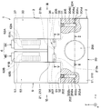
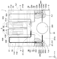
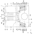
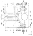
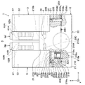
- the refrigeration cycle apparatus 1 of the present embodiment has a horizontal structure in which the compressor 2, the radiator 3, the decompression device 4, the evaporator 5, and the blower 6 are arranged side by side in a horizontal direction orthogonal to the z direction.
- x, y, and z indicate three directions orthogonal to each other.
- the x direction is one direction parallel to the horizontal direction when the vehicle is mounted
- the y direction is parallel to the horizontal direction and orthogonal to the x direction
- the z direction is orthogonal to the horizontal direction (that is, vertical) Direction).
- the compressor 2 is composed of a fluid pump that sucks refrigerant and compresses and discharges the sucked refrigerant.
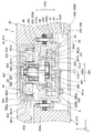
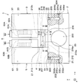
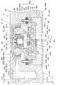
- the compressor 2 has a compressor housing 20 that houses a compression mechanism section 24 and an electric motor 25 described later.
- the compressor housing 20 has a convex three-dimensional shape with a substantially central portion in the x direction protruding in the y direction. Inside the compressor housing 20, an accommodation space 200 for accommodating a later-described compression mechanism portion 24 and an electric motor 25 is formed at a substantially central portion in the x direction.
- the compressor housing 20 is formed with a suction flow path 202 for introducing a refrigerant into the accommodation space 200 and a discharge flow path 204 for leading the refrigerant from the accommodation space 200.
- the suction flow path 202 and the discharge flow path 204 are formed at portions facing each other across the accommodation space 200 in the compressor housing 20.
- the suction flow path 202 is a flow path that communicates with the accommodation space 200 inside the compressor housing 20.
- the suction flow path 202 is configured by a flow path bent in an L shape formed by a through hole 202a extending in the x direction and a bottomed hole 202b extending in the y direction.
- the through hole 202a extending in the x direction forming the suction flow path 202 has an opening 202c that opens to the outside closed by a columnar blocking member 202d.
- a refrigerant suction portion 203 that is directly connected so that a low pressure outlet 52 of the evaporator 5 described later is not exposed to the outside.
- the refrigerant suction part 203 is provided to introduce the refrigerant into the suction flow path 202.
- the refrigerant suction portion 203 is an opening that opens at the end of the bottomed hole 202b that forms the suction flow path 202, and has a size that allows a low-pressure outlet 52 of the evaporator 5 to be described later to be fitted therein. ing.
- directly connected means a state in which the members are directly connected without being separated from each other, and can be understood as a state in which the members are connected to each other without passing through the refrigerant pipe.
- the discharge flow path 204 is a flow path communicating with the accommodation space 200 inside the compressor housing 20.
- the discharge flow path 204 is a flow path bent in an L shape formed by a through hole 204a extending in the x direction and a bottomed hole 204b extending in the y direction.
- an opening 204c that opens to the outside is closed by a columnar closing member 204d.
- a refrigerant discharge portion 205 that is directly connected so that a high-pressure introduction portion 31 of the radiator 3 to be described later is not exposed to the outside is provided at the end of the discharge flow passage 204 on the downstream side of the refrigerant flow.
- the refrigerant discharge unit 205 is provided to lead the refrigerant flowing through the discharge flow path 204 to the outside of the compressor housing 20.
- the refrigerant discharge part 205 is an opening that opens at the end of the bottomed hole 204b that forms the discharge flow path 204, and has a size that allows the high-pressure introduction part 31 of the radiator 3 to be described later to be fitted therein. ing.
- the compressor housing 20 is a sealed container configured by a plurality of metal members being combined in an airtight manner.
- the compressor housing 20 includes a main housing part 21 in which a suction flow path 202 and a discharge flow path 204 are formed, a plate-shaped sub housing part 22 that closes an opening formed in the main housing part 21, and An internal housing portion 23 is included.
- the main housing portion 21 is formed with a bottomed cylindrical hole for forming the above-described accommodation space 200 at a substantially central portion in the x direction.
- the main housing portion 21 includes a bottom wall portion 211 that forms the bottom surface of the housing space 200, a side wall portion 212 that forms the side surface of the housing space 200, and a bulging portion 213 that protrudes in the y direction at the side wall portion 212. .
- the bottom wall portion 211, the side wall portion 212, and the bulging portion 213 are configured as an integral structure.
- the suction channel 202 and the discharge channel 204 are formed in the side wall portion 212.
- a step portion 212a is formed so that the cross-sectional area gradually increases from the bottom wall portion 211 toward the opening side.
- the step portion 212 a is formed over the entire inner periphery of the side wall portion 212.
- the bulging portion 213 protrudes in the y direction from a portion that forms the accommodation space 200 in the side wall portion 212.
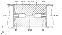
- the bulging portion 213 is a portion of the compressor housing 20 that overlaps a part of the radiator 3 and a part of the evaporator 5 in the x direction.
- the bulging portion 213 is formed with a through hole 213a penetrating along the x direction.
- the through hole 213a has a small cross-sectional area at a substantially central portion in the x direction so that the decompression action of the refrigerant is exhibited.
- the decompression device 4 is configured by a part of the through hole 213 a provided in the bulging portion 213. The details of the decompression device 4 will be described later.
- the bulging portion 213 is formed with an intermediate introduction portion 206 that is directly connected to a portion facing the radiator 3 so that a high-voltage outlet portion 32 of the radiator 3 to be described later is not exposed to the outside.
- the intermediate introduction unit 206 is provided to guide the refrigerant that has passed through the radiator 3 to the decompression device 4.
- the intermediate introduction part 206 is an opening part opened to one end side of the through hole 213a, and has a size capable of fitting a high voltage lead-out part 32 of the radiator 3 described later.
- the bulging portion 213 is formed with an intermediate lead-out portion 207 that is directly connected to a portion facing the evaporator 5 so that a low-pressure introduction portion 51 of the evaporator 5 described later is not exposed to the outside.
- the intermediate deriving unit 207 is provided to guide the refrigerant that has passed through the decompression device 4 to the evaporator 5.
- the intermediate lead-out portion 207 is an opening that opens to the other end side of the through hole 213a, and has a size that allows a low-pressure introduction portion 51 of the evaporator 5 to be described later to be fitted therein.
- the storage space 200, the suction flow path 202, and the discharge flow path 204 constitute a refrigerant flow path from the refrigerant suction section 203 to the refrigerant discharge section 205 via the compression mechanism section 24.
- the through hole 213a constitutes a refrigerant flow path from the intermediate introduction part 206 to the intermediate lead-out part 207 via the decompression device 4.
- the sub-housing portion 22 is composed of a plate-like member having a size capable of airtightly closing the opening of the main housing portion 21.
- the compressor housing 20 is formed with an accommodation space 200 for accommodating the compression mechanism portion 24 and the electric motor 25 by the airtight combination of the main housing portion 21 and the sub housing portion 22.
- a seal member made of a gasket, an O-ring, or the like is disposed between the main housing portion 21 and the sub housing portion 22.
- the main housing portion 21 and the sub housing portion 22 constitute an outer shell forming portion.
- the inner housing portion 23 functions as a support member that supports the compression mechanism portion 24 and the electric motor 25 in the compressor housing 20.
- the inner housing portion 23 includes a cylindrical tubular portion 231 through which the main shaft 26 is inserted, and an annular flange portion 232 that is continuous with the tubular portion 231 and extends radially outward of the main shaft 26. .
- the cylindrical portion 231 and the flange portion 232 are configured as an integral structure.
- the direction extending along the axis CLm of the main shaft 26 is defined as the axial direction DRa
- the direction orthogonal to the axial direction DRa is defined as the radial direction DRr.
- the cylindrical portion 231 is formed with an insertion hole 231a through which the main shaft 26 is inserted.
- the insertion hole 231a is a through hole penetrating in the axial direction DRa.
- the insertion hole 231a is provided with an inner protrusion 231b for restricting the position of the first bearing portion 263 and the second bearing portion 264 that support the main shaft 26 in the axial direction DRa.
- the cylindrical portion 231 includes a first cylindrical portion 233 protruding from the compression mechanism portion 24 side toward the bottom wall portion 211 of the main housing portion 21, and a second protruding from the electric motor 25 side toward the sub housing portion 22.
- a cylindrical portion 234 is included.
- the first tube portion 233 is a support portion that supports the electric motor 25.
- the second cylinder portion 234 is a support portion that supports the compression mechanism portion 24.
- the flange portion 232 protrudes outward in the radial direction DRr from the tubular portion 231 so as to face the end surface of the step portion 212a of the main housing portion 21.
- the flange portion 232 has a plurality of through holes 232a through which the fastening bolts 27 are inserted with respect to the outer portion thereof. Further, the flange portion 232 is formed with a groove 232 b into which the rotation prevention pin P is fitted at a portion facing the orbiting scroll 242.
- the internal housing portion 23 configured as described above is connected to the main housing portion 21 via the buffer member 28.
- the inner housing part 23 is connected to the main housing part 21 by the fastening bolts 27 with the buffer member 28 interposed between the flange part 232 and the end surface of the step part 212a of the main housing part 21. ing.
- the buffer member 28 is formed of an elastic body that blocks communication between the suction space 200A and the discharge space 200B and can attenuate vibrations of the compression mechanism 24 and the electric motor 25.
- the elastic body has an annular shape having a size capable of covering the end surface of the step portion 212a.
- the elastic body is made of, for example, a rubber material having excellent gas barrier properties and heat resistance.
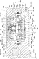
- the electric motor 25 is a so-called outer rotor motor. That is, the electric motor 25 includes a stator 251 that generates a rotating magnetic field, and a rotor 252 that rotates outside the stator 251 by the rotating magnetic field generated by the stator 251.
- the stator 251 includes a cylindrical stator core 251a formed of a metal magnetic material, and a stator coil 251b wound around the stator core 251a.
- the stator 251 is fixed to the outside of the first tube portion 233 of the inner housing portion 23 by a fixing method such as press fitting.
- the rotor 252 includes a cylindrical rotor main body portion 252a, an end plate portion 252b that closes one opening of the rotor main body portion 252a, and a plurality of magnets 252c embedded inside the rotor main body portion 252a.
- a plurality of magnets 252c are embedded in the rotor body 252a at predetermined intervals in the circumferential direction.
- a through hole for receiving the motor side end portion 261 of the main shaft 26 is formed in a substantially central portion.
- the electric motor side end 261 is an end closer to the electric motor 25 than the compression mechanism 24 in the main shaft 26.
- the rotor 252 is coupled to the main shaft 26 by a coupling mechanism 29 in a state where a minute gap is formed between the magnet 252c and the stator core 251a.
- the connection mechanism 29 between the rotor 252 and the main shaft 26 is configured by a screw groove 291 formed in the motor-side end 261, a connection bolt 292 screwed into the screw groove 291, and the like.
- the main shaft 26 is a transmission member that transmits the rotational power of the electric motor 25 to the compression mechanism 24.
- the main shaft 26 has an electric motor side end portion 261 provided with the above-described coupling mechanism 29 and a compression side end portion 262 which is an end portion on the opposite side of the electric motor side end portion 261 in the axial direction DRa.
- the motor-side end portion 261 of the main shaft 26 is configured to be exposed to the outside from the insertion hole 231a when the main shaft 26 is inserted into the insertion hole 231a of the cylindrical portion 231. That is, the dimension of the axial direction DRa is set so that the motor-side end 261 is exposed to the outside of the insertion hole 231a when the main shaft 26 is inserted into the insertion hole 231a of the cylindrical portion 231.
- the main shaft 26 is rotatably supported by the first bearing portion 263 and the second bearing portion 264.
- the 1st bearing part 263 supports the site
- the 2nd bearing part 264 supports the site
- Each of the first bearing portion 263 and the second bearing portion 264 is installed inside the cylindrical portion 231 of the inner housing portion 23.
- the first bearing portion 263 is disposed so as to overlap the stator 251 in the radial direction DRr. That is, the 1st bearing part 263 is installed inside the site
- FIG. Thereby, the compressor 2 has a small physique in the axial direction DRa.
- An eccentric shaft portion 265 that is eccentric with respect to the axial center CLm of the main shaft 26 is connected to the compression side end portion 262 of the main shaft 26.
- the eccentric shaft portion 265 has a shaft center CLs that is offset from the shaft center CLm of the main shaft 26 in the radial direction DRr of the main shaft 26.
- the eccentric shaft portion 265 is connected to the compression mechanism portion 24 via the third bearing portion 266.
- the outer peripheral side of the eccentric shaft portion 265 is connected to the orbiting scroll 242 of the compression mechanism portion 24 via the third bearing portion 266.
- the third bearing portion 266 is fixed inside a boss portion 242c of the orbiting scroll 242 described later by means such as press fitting.
- the eccentric shaft portion 265 when the eccentric shaft portion 265 is connected to the main shaft 26, the centrifugal force of the eccentric shaft portion 265, the third bearing portion 266, and the orbiting scroll 242 acts on the main shaft 26. For this reason, the eccentric shaft portion 265 is provided with a weight balance 267 for suppressing the centrifugal force acting on the main shaft 26.
- the compression mechanism unit 24 is a scroll that compresses the refrigerant sucked from the outside of the orbiting scroll 242 by rotating the orbiting scroll 242 with respect to the fixed scroll 241 while the fixed tooth portion 241b and the orbiting tooth portion 242b are engaged with each other. It consists of a compression mechanism part of the mold.
- the fixed scroll 241 has a fixed substrate portion 241a fixed inside the second cylindrical portion 234 of the inner housing portion 23, and a spiral fixed tooth portion 241b protruding from the fixed substrate portion 241a.
- a refrigerant discharge port 241c that discharges the refrigerant compressed by the compression mechanism unit 24 is formed at a substantially central portion of the fixed substrate unit 241a.
- the fixed substrate portion 241 a is provided with a reed valve 241 d for preventing the refrigerant from flowing backward from the refrigerant discharge port 241 c to the compression mechanism portion 24.
- the orbiting scroll 242 has a spiral substrate portion 242a disposed facing the surface of the fixed substrate portion 241a on which the fixed tooth portion 241b is formed, and a spiral shape protruding from the orbiting substrate portion 242a toward the fixed substrate portion 241a.
- a swivel tooth portion 242b is provided.
- a boss portion 242c that receives the eccentric shaft portion 265 and the third bearing portion 266 is formed at a substantially central portion of the turning substrate portion 242a.
- a circular pin receiving hole H constituting a rotation prevention mechanism of the turning scroll 242 is formed in the turning substrate portion 242a together with the rotation prevention pin P.
- a compression chamber for compressing the refrigerant is formed between the fixed tooth portion 241 b and the orbiting tooth portion 242 b by meshing the fixed tooth portion 241 b and the orbiting tooth portion 242 b.
- a refrigerant introduction space for introducing a refrigerant into the compression chamber is formed outside the orbiting scroll 242.
- the compressor 2 configured in this way, for example, after connecting an assembly in which the compression mechanism portion 24 and the electric motor 25 are assembled to the internal housing portion 23 to the main housing portion 21, opens the opening of the main housing portion 21. It is obtained by closing with the sub housing part 22.
- the heat radiator 3 is a heat exchanger that dissipates the high-pressure refrigerant discharged from the compressor 2 by heat exchange with air supplied by a first air blower 6A of the air blower 6 described later.
- the radiator 3 is installed directly with respect to the compressor housing 20.
- the radiator 3 is provided with a high-pressure introduction part 31 for introducing the refrigerant discharged from the compressor 2 into the interior.
- the high-pressure introducing portion 31 is configured by a tubular member that protrudes toward the compressor housing 20 along the y direction.
- the radiator 3 is provided with a high-pressure derivation unit 32 for deriving the refrigerant that has passed through the radiator 3 to the decompression device 4 side.
- the high pressure lead-out part 32 is configured by a cylindrical member that protrudes toward the compressor housing 20 along the x direction.
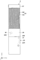
- the radiator 3 is connected to the heat exchange core portion 33 composed of a plurality of tubes 34 and fins 35, and the longitudinal ends of the plurality of tubes 34.
- the heat exchanger includes a first high-pressure tank 36 and a second high-pressure tank 37.
- the radiator 3 is configured such that the refrigerant flowing into a part of the heat exchange core portion 33 from the first high pressure tank 36 flows into the first high pressure tank 36 via the second high pressure tank 37 and the remaining portion of the heat exchange core portion 33. Has been.
- the radiator 3 configured as described above is installed with respect to the main housing portion 21 so that the first high-pressure tank 36 is in contact with both the side wall portion 212 and the bulging portion 213 of the main housing portion 21.
- a high pressure introducing portion 31 is provided at a portion of the first high pressure tank 36 that faces the refrigerant discharge portion 205 of the compressor housing 20.
- a high pressure outlet 32 is provided at a portion of the first high pressure tank 36 that faces the intermediate inlet 206 of the compressor housing 20.
- the radiator 3 is rotated around the high-pressure deriving unit 32 in a state where the high-pressure deriving unit 32 is fitted to the intermediate introducing unit 206, and the high-pressure introducing unit 31 is fitted to the refrigerant discharge unit 205.
- the compressor housing 20 can be connected.
- the decompression device 4 decompresses the refrigerant that has passed through the radiator 3.
- the decompression device 4 of the present embodiment is formed inside the compressor housing 20.
- the decompression device 4 according to the present embodiment is configured by a fixed throttle formed in a through hole 213 a provided in the bulging portion 213 of the compressor housing 20.
- the intermediate introduction portion 206 and the intermediate lead-out portion 207 in the through hole 213 a there is a reduction portion 213 b having a smaller cross-sectional area than the intermediate introduction portion 206 and the intermediate lead-out portion 207. Is formed.
- the fixed aperture constituting the decompression device 4 is configured by a reduced portion 213b of the through hole 213a.
- the evaporator 5 is a heat exchanger that evaporates the low-pressure refrigerant decompressed by the decompression device 4 by heat exchange with air supplied by a second air blower 6B of the blower 6 described later.
- the evaporator 5 is installed directly with respect to the compressor housing 20 similarly to the radiator 3.
- the radiator 3 and the evaporator 5 of this embodiment are installed with respect to the compressor housing 20 so as to face each other via the bulging portion 213 of the compressor housing 20.
- the evaporator 5 is provided with a low-pressure introduction part 51 for introducing the refrigerant decompressed by the decompression device 4 into the interior.
- the low-pressure introduction part 51 is configured by a cylindrical member that protrudes toward the compressor housing 20 along the y direction.
- the evaporator 5 is provided with a low-pressure deriving unit 52 for deriving the refrigerant that has passed through the evaporator 5 to the compressor 2 side.
- the low pressure lead-out portion 52 is configured by a tubular member that protrudes toward the compressor housing 20 along the x direction.
- the evaporator 5 includes a heat exchange core portion 53 composed of a plurality of tubes 54 and fins 55, and a first end connected to the longitudinal ends of the plurality of tubes 54.
- the heat exchanger includes a first low pressure tank 56 and a second low pressure tank 57.
- the evaporator 5 is configured such that the refrigerant that has flowed into the heat exchange core portion 53 from the first low pressure tank 56 flows into the first low pressure tank 56 via the second low pressure tank 57 and the remainder of the heat exchange core portion 53. Has been.
- the evaporator 5 configured as described above is installed with respect to the main housing portion 21 so that the first low-pressure tank 56 is in contact with both the side wall portion 212 and the bulging portion 213 of the main housing portion 21.
- a low pressure introduction part 51 is provided in a portion of the first low pressure tank 56 that faces the intermediate outlet part 207 of the compressor housing 20.
- a low pressure outlet 52 is provided at a portion of the first low pressure tank 56 that faces the refrigerant suction portion 203 of the compressor housing 20.
- the evaporator 5 and the compressor housing 20 can be connected by a method similar to the method of connecting the radiator 3 and the compressor housing 20. That is, the evaporator 5 rotates around the low-pressure introduction part 51 in a state where the low-pressure introduction part 51 is fitted to the intermediate lead-out part 207 and fits the low-pressure lead-out part 52 to the refrigerant suction part 203. It can be connected to the housing 20.
- the blower 6 supplies air to the radiator 3 and the evaporator 5. As shown in FIG. 1, the blower 6 is disposed between the radiator 3 and the evaporator 5.
- the blower 6 includes a first blower 6 ⁇ / b> A that supplies air to the radiator 3 and a second blower 6 ⁇ / b> B that supplies air to the evaporator 5.
- the first air blower 6A includes a warm air case 61A through which warm air heated by the radiator 3 circulates, a warm air fan 62A accommodated in the warm air case 61A, and a fan motor 63A that drives the warm air fan 62A.
- the hot air case 61A is connected to a hot air blowing duct that blows hot air near the seat or a hot air exhaust duct that exhausts hot air to a space other than the vicinity of the seat.
- the second air blower 6B includes a cold air case 61B through which the cold air cooled by the evaporator 5 flows, a cold air fan 62B accommodated in the cold air case 61B, and a fan motor 63B that drives the cold air fan 62B.
- the cold air case 61B is connected to a cold air outlet duct that blows out cold air in the vicinity of the seat or a cold air exhaust duct that exhausts the cold air to a space other than the vicinity of the seat.
- the operation of the refrigeration cycle apparatus 1 of the present embodiment will be described with reference to FIG.
- power is supplied from a battery mounted on the vehicle to the stator 251 of the electric motor 25 and the fan motors 63A and 63B of the blower 6.
- the refrigerant circulates in the cycle of the refrigeration cycle apparatus 1 by driving the compression mechanism unit 24 by the electric motor 25.
- the hot air fan 62A and the cold air fan 62B are driven by the fan motors 63A and 63B, so that an airflow passing through the radiator 3 and an airflow passing through the evaporator 5 are generated.
- the refrigerant discharged from the compression mechanism portion 24 into the discharge space 200B flows into the radiator 3 via the discharge flow path 204 and the refrigerant discharge portion 205 as shown by an arrow Fc1 in FIG.
- the refrigerant flowing into the radiator 3 is in the order of the first high pressure tank 36 ⁇ the heat exchange core portion 33 ⁇ the second high pressure tank 37 ⁇ the heat exchange core portion 33 ⁇ the first high pressure tank 36. After flowing, it flows into the decompression device 4 side through the intermediate introduction part 206.
- the refrigerant that has flowed into the radiator 3 passes through the heat exchange core portion 33, the refrigerant exchanges heat with the air supplied by the first air blowing portion 6 ⁇ / b> A to radiate heat.
- the air supplied by the first blower 6A is heated by the refrigerant flowing through the radiator 3 and then blown into a desired space, as indicated by an arrow Fa1 in FIG.
- the refrigerant that has flowed into the decompression device 4 is decompressed when passing through the reduced portion 213b of the through hole 213a constituting the fixed throttle.
- the refrigerant decompressed by the decompression device 4 flows into the evaporator 5 through the intermediate outlet 207.
- the refrigerant flowing into the evaporator 5 is in the order of the first low pressure tank 56 ⁇ the heat exchange core portion 53 ⁇ the second low pressure tank 57 ⁇ the heat exchange core portion 53 ⁇ the first low pressure tank 56.
- the refrigerant flows into the compressor 2 through the refrigerant suction portion 203.
- the refrigerant flowing into the evaporator 5 evaporates by exchanging heat with the air supplied by the second blower 6B when passing through the heat exchange core 53.
- the air supplied by the second blower 6B is cooled by the endothermic action at the time of evaporation of the refrigerant flowing through the evaporator 5, and then blown into a desired space.
- the refrigerant sucked into the compressor 2 flows into the accommodation space 200 (specifically, the suction space 200A) through the suction flow path 202 as indicated by an arrow Fc4 in FIG. Thereafter, the refrigerant in the suction space 200 ⁇ / b> A is sucked into the compression mechanism unit 24, and the sucked refrigerant is compressed by the compression mechanism unit 24.
- the refrigeration cycle apparatus 1 described above includes a refrigerant discharge unit 205 that is directly connected to the compressor housing 20 so that the high-pressure introduction part 31 of the radiator 3 is not exposed to the outside, and a low-pressure derivation part 52 of the evaporator 5.
- a refrigerant suction portion 203 that is directly connected so as not to be exposed to the outside is provided.
- the pressure pulsation of the compressor 2 and the stress due to mechanical vibration cause the radiator 3 and the evaporator 5 in the cycle constituent devices. It acts directly on such a large and durable device. For this reason, the durability of the refrigeration cycle apparatus 1 can be ensured as compared with the conventional structure in which the compressor 2, the radiator 3, and the evaporator 5 are connected via the refrigerant pipe.
- the refrigeration cycle apparatus 1 can be simplified and downsized.
- the pressure loss of the refrigerant in the cycle increases as the refrigerant flow path becomes longer, and decreases as the refrigerant flow path becomes shorter. For this reason, if it is set as the structure where the heat radiator 3 and the evaporator 5 are directly connected to the compressor housing 20, compared with the conventional structure where the compressor 2, the heat radiator 3, and the evaporator 5 are connected via refrigerant
- the compressor 2 the radiator 3, and the evaporator 5 are connected via the refrigerant pipe
- the refrigerant pipe is exposed to the outside, so heat loss due to heat exchange with the surrounding environment is inevitable.
- the high pressure introduction part 31 of the radiator 3 is directly connected to the refrigerant discharge part 205 so as not to be exposed to the outside, and the low pressure derivation part 52 of the evaporator 5 is exposed to the outside. It is directly connected to the refrigerant suction part 203 so as not to occur. According to this, heat loss due to heat exchange with the surrounding environment can be suppressed.
- the decompression device 4 is provided inside the compressor housing 20.
- the compressor housing 20 is directly connected so that the high pressure lead-out portion 32 of the radiator 3 is directly connected so as not to be exposed to the outside, and the low pressure introduction portion 51 of the evaporator 5 is not exposed to the outside.
- An intermediate derivation unit 207 is provided.
- the refrigeration cycle apparatus 1 is compared with the conventional structure in which the radiator 3, the decompression device 4, and the evaporator 5 are connected via the refrigerant pipe. It is possible to ensure durability.
- the refrigeration cycle apparatus 1 can be simplified as compared with the case where a separate decompression device 4 is installed outside the compressor housing 20. Can do.
- the refrigeration cycle apparatus 1 has a structure in which a portion of the compressor housing 20 constituting the decompression device 4 is directly connected to the radiator 3 and the evaporator 5.
- the refrigeration cycle apparatus 1 is simplified and miniaturized. Can be achieved.
- the decompression device 4 of the present embodiment is configured by a fixed throttle formed in a through hole 213 a inside the compressor housing 20. If the decompression device 4 is configured with a fixed throttle formed in the compressor housing 20 as described above, the number of parts is reduced as compared with a configuration in which the decompression device 4 includes a variable throttle mechanism, and thus the refrigeration cycle apparatus 1 Can be simplified and downsized.
- the compression mechanism unit 24 of the compressor 2 is configured by a scroll type compression mechanism unit. Since the scroll-type compression mechanism section does not require a movable member that moves in the axial direction DRa unlike the reciprocating-type compression mechanism section, the physique of the axial direction DRa can be reduced in size as the compression mechanism section 24 as a whole. For this reason, if a scroll type compression mechanism part is employ
- the compressor 2 of the present embodiment is configured such that the compression mechanism portion 24 and the electric motor 25 are supported by the inner housing portion 23 accommodated in the main housing portion 21 and the sub housing portion 22 that form the outer shell.
- the internal housing portion 23 is connected to the main housing portion 21 via a buffer member 28 for attenuating vibrations of the compression mechanism portion 24 and the electric motor 25.
- the vibration generated in the compression mechanism portion 24 and the electric motor 25 is attenuated by the buffer member 28, so that the vibration of the compression mechanism portion 24 and the electric motor 25 occurs in the main housing portion 21 and the sub housing portion 22 of the compressor housing 20. It becomes difficult to be transmitted.
- the vibration applied to the main housing portion 21 in which the refrigerant discharge portion 205 and the refrigerant suction portion 203 are formed is suppressed, thereby suppressing the stress applied to the connecting portion between the compressor housing 20, the radiator 3 and the evaporator 5. Can do. This greatly contributes to improving the durability of the refrigeration cycle apparatus 1.
- the sub housing is attached to the main housing portion 21. It is obtained by connecting the parts 22. According to this, if the compression mechanism part 24, the electric motor 25, and the internal housing part 23 are unitized, the assembling property at the time of manufacture of the compressor 2 can be improved.
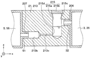
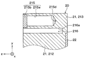
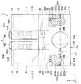
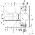
- the high-pressure side reservoir 215 is provided to store excess liquid refrigerant in the cycle. As shown in FIG. 8, the high-pressure side reservoir 215 is provided for the bulging portion 213 of the main housing portion 21 in the compressor housing 20. More specifically, the high-pressure side reservoir 215 is provided between the intermediate introduction part 206 and the reduction part 213 b constituting the decompression device 4 in the through hole 213 a formed in the bulging part 213. That is, the high-pressure side reservoir 215 is provided on the upstream side of the refrigerant flow with respect to the reduced portion 213b in the through hole 213a.
- the high-pressure side reservoir 215 includes a bottomed hole 215a extending in the vertical direction (that is, the z direction) and a closing plate 215b that closes the opening of the bottomed hole 215a. ing.
- the bottomed hole 215a is formed with an upstream opening 215c through which the refrigerant from the intermediate introduction section 206 flows and a downstream opening 215d through which the refrigerant stored inside flows out to the reduction section 213b, which is the decompression device 4.
- the downstream opening 215d is formed on the lower side in the vertical direction than the upstream opening 215c so that the liquid refrigerant stored in the high-pressure reservoir 215 flows toward the reducing portion 213b.
- the decompression device 4 and the high-pressure side storage portion 215 are formed inside the compressor housing 20, the refrigerant flowing through the decompression device 4 or the liquid refrigerant stored in the high-pressure side storage portion 215 and the compression mechanism portion 24 are sucked. Heat exchange with the refrigerant and the refrigerant discharged from the compression mechanism 24. In particular, when the liquid refrigerant stored in the high-pressure side storage unit 215 and the refrigerant discharged from the compression mechanism unit 24 exchange heat, there is a concern that the liquid refrigerant stored in the high-pressure side storage unit 215 evaporates.
- a heat exchange suppression unit 216 is provided for the compressor housing 20.
- the heat exchange suppression unit 216 includes an intermediate deriving unit from the intermediate introduction unit 206 through the refrigerant flow path extending from the refrigerant suction unit 203 to the refrigerant discharge unit 205 via the compression mechanism unit 24 and the decompression device 4.
- the groove 216 a is provided between the refrigerant flow path reaching 207.
- the groove 216a is formed in a slit shape.
- the refrigeration cycle apparatus 1 of the present embodiment described above has the same configuration as that of the first embodiment. For this reason, the refrigerating cycle apparatus 1 of this embodiment can obtain the effect produced from the same configuration as that of the first embodiment, similarly to the first embodiment. The same applies to the following embodiments.
- the refrigeration cycle apparatus 1 of the present embodiment is provided with a high-pressure side reservoir 215 that can store liquid refrigerant in the compressor housing 20.
- a high-pressure side reservoir 215 that can store liquid refrigerant in the compressor housing 20.
- the high-pressure side reservoir 215 is formed with an upstream opening 215c that allows the refrigerant from the intermediate introduction portion 206 to flow therein, and a downstream opening 215d that allows the refrigerant stored therein to flow out to the decompression device 4 side.
- the downstream opening 215d is formed on the lower side in the vertical direction than the upstream opening 215c.
- the liquid refrigerant stored in the high-pressure side storage unit 215 easily flows to the decompression device 4 side. That is, a liquid refrigerant with a small enthalpy tends to flow on the decompression device 4 side. As a result, the difference in enthalpy before and after the evaporator 5 can be secured, and the heat absorption capability of the evaporator 5 can be improved.
- the “vertical direction” means a direction perpendicular to the horizontal plane, and can be interpreted to mean a direction in which gravity acts.
- the compressor housing 20 the refrigerant flow from the refrigerant suction part 203 to the refrigerant discharge part 205 via the compression mechanism part 24 and the refrigerant flow from the intermediate introduction part 206 to the intermediate lead-out part 207 via the decompression device 4.
- a heat exchange suppression unit 216 is provided for thermally dividing the path.
- the downstream opening 215d of the high-pressure side reservoir 215 is formed on the lower side in the vertical direction than the upstream opening 215c is described, but the present invention is not limited to this.
- the high-pressure side reservoir 215 may be formed at a position where the downstream opening 215d is equivalent to the upstream opening 215c in the vertical direction.
- the refrigeration cycle apparatus 1 may have a configuration in which the heat exchange suppression unit 216 in the compressor housing 20 is omitted.
- the refrigeration cycle apparatus 1 may have a configuration in which the high-pressure side reservoir 215 in the compressor housing 20 is omitted.
- the heat exchange suppression unit 216 may be formed of a thermal buffer made of a material having a higher thermal resistance than the compressor housing 20.
- the high-pressure side reservoir 215 is provided in the compressor housing 20 of the refrigeration cycle apparatus 1 having a horizontal structure
- the configuration in which the high pressure side reservoir 215 is provided in the compressor housing 20 is a refrigeration cycle apparatus having a vertical structure in which the radiator 3, the decompression device 4, the evaporator 5, and the blower 6 are installed above the compressor 2. 1 is also applicable.
- the high-pressure side storage unit 215 may include a bottomed hole 215a extending in the vertical direction (that is, the z direction) so that the liquid refrigerant can be stored.
- the present embodiment is different from the first embodiment in that the decompression device 4 is disposed outside the compressor housing 20.
- portions different from those in the first embodiment will be mainly described, and description of portions similar to those in the first embodiment may be omitted.
- the compressor housing 20 of the present embodiment has a rectangular parallelepiped outer shape in which a substantially central portion in the x direction does not protrude in the y direction. That is, the compressor housing 20 of the present embodiment is not provided with a configuration corresponding to the bulging portion 213 in the first embodiment.
- the decompression device 4 of the present embodiment is disposed outside the compressor housing 20. Specifically, the decompression device 4 is disposed between the radiator 3 and the evaporator 5 so as to be sandwiched between the first high-pressure tank 36 of the radiator 3 and the first low-pressure tank 56 of the evaporator 5. Yes.
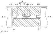
- the decompression device 4 includes a valve main body 41 constituting an outer shell, and a throttle mechanism portion 42 provided inside the valve main body 41.
- the valve body 41 is composed of a metal block body.
- the valve body 41 is formed with a through hole 411 penetrating along the x direction. Inside the through hole 411, a throttle mechanism portion 42 that exerts a pressure reducing action of the refrigerant is disposed.
- the throttle mechanism section 42 is configured by a cylindrical orifice 421 in which a throttle channel 421a is formed.
- the valve main body 41 is formed with a valve introduction portion 412 that is directly connected to a portion facing the radiator 3 so that the high-pressure outlet portion 32 of the radiator 3 is not exposed to the outside.
- the valve introduction part 412 is an opening that opens to one end side of the through hole 411 of the valve main body 41, and has a size that allows the high pressure lead-out part 32 of the radiator 3 to be fitted therein.
- the valve main body 41 is formed with a valve lead-out portion 413 that is directly connected to a portion facing the evaporator 5 so that the low-pressure introduction portion 51 of the evaporator 5 is not exposed to the outside.
- the valve lead-out portion 413 is an opening that opens to the other end side of the through hole 411 of the valve body 41 and has a size that allows the low-pressure introduction portion 51 of the evaporator 5 to be fitted therein.
- the refrigeration cycle apparatus 1 of the present embodiment has a structure in which a decompression device 4 provided outside the compressor housing 20 is directly connected to the radiator 3 and the evaporator 5. According to this, since the number of parts is reduced as compared with the conventional structure in which the radiator 3, the decompression device 4, and the evaporator 5 are connected via the refrigerant pipe, the refrigeration cycle apparatus 1 is simplified and downsized. be able to.
- FIGS. (Fourth embodiment) Next, a fourth embodiment will be described with reference to FIGS.
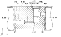
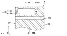
- the present embodiment is different from the third embodiment in that a high-pressure side reservoir 415 is provided in the valve body 41 of the decompression device 4.
- a high-pressure side reservoir 415 is provided in the valve body 41 of the decompression device 4.
- portions different from the third embodiment will be mainly described, and description of portions similar to the third embodiment may be omitted.
- the valve main body 41 has a reduction portion 414 having a smaller cross-sectional area than the valve introduction portion 412 and the valve lead-out portion 413 between the valve introduction portion 412 and the valve lead-out portion 413 in the through hole 411. Is provided.
- the reduction unit 414 functions as a throttle mechanism unit that exerts a decompression action of the refrigerant.
- valve main body 41 is provided with a high-pressure side storage section 415 for storing a liquid refrigerant that is excessive in the cycle.
- the high-pressure side reservoir 415 is provided between the valve introduction part 412 and the reduction part 414 constituting the throttle mechanism part 42 in the through hole 411 formed in the valve main body 41.
- the high-pressure side reservoir 415 is provided on the upstream side of the refrigerant flow with respect to the reduced portion 414 in the through hole 411.
- the high-pressure side reservoir 415 includes a bottomed hole 415a extending in the z direction and a closing plate 415b that closes the opening of the bottomed hole 415a.
- the bottomed hole 415a has an upstream opening 415c through which the refrigerant from the valve introduction portion 412 flows, and a downstream opening 415d through which the refrigerant stored inside flows out to the reducing portion 414 constituting the throttle mechanism. Is formed.
- the high-pressure side reservoir 415 has a downstream opening 415d on the lower side in the vertical direction (that is, the z direction) than the upstream opening 415c so that the liquid refrigerant stored in the high-pressure reservoir 415 flows toward the reducing portion 414. Is formed.
- the heat reducing unit 416 is provided between the decompression device 4 configured in this manner and the compressor housing 20.
- the heat exchange suppression unit 416 includes a valve introduction unit via a refrigerant flow path from the refrigerant suction unit 203 to the refrigerant discharge unit 205 via the compression mechanism unit 24 and a reduction unit 414 which is a throttle mechanism unit. It is comprised by the space
- the through hole 411 formed in the valve body 41 constitutes a refrigerant flow path from the valve introduction part 412 to the valve lead-out part 413 via the reduction part 414.
- the refrigeration cycle apparatus 1 of the present embodiment described above has the same configuration as that of the third embodiment. For this reason, the refrigeration cycle apparatus 1 of the present embodiment can obtain the operational effects produced from the configuration common to the third embodiment, similarly to the third embodiment.
- a high-pressure side storage unit 415 capable of storing liquid refrigerant is provided between the valve introduction unit 412 and the reduction unit 414 functioning as the decompression device 4 in the through hole 411 of the valve body 41. ing.
- the liquid refrigerant which becomes the excess in a cycle can be temporarily stored in the high pressure side storage part 215. Sometimes a shortage of refrigerant in the cycle can be avoided.
- the high-pressure side storage section 415 has an upstream opening 415c that allows the refrigerant from the valve introduction section 412 to flow therein, and the downstream that discharges the refrigerant stored therein to the reduction section 414 that is the throttle mechanism section 42.
- a side opening 415d is formed.
- the downstream opening 415d is formed on the lower side in the vertical direction than the upstream opening 415c.
- the liquid refrigerant stored in the high-pressure side storage unit 415 easily flows to the reduction unit 414 side. That is, a liquid refrigerant having a small enthalpy is likely to flow on the reducing portion 414 side. As a result, the difference in enthalpy before and after the evaporator 5 can be secured, and the heat absorption capability of the evaporator 5 can be improved.
- a refrigerant flow path from the refrigerant suction part 203 to the refrigerant discharge part 205 and a refrigerant flow path from the valve introduction part 412 to the valve lead-out part 413 are thermally connected.
- a heat exchange suppressing unit 416 for dividing is provided. According to this, unnecessary heat exchange between the refrigerant flowing through the reduction unit 414 and the liquid refrigerant stored in the high-pressure side storage unit 415 and the refrigerant sucked into the compression mechanism unit 24 and the refrigerant discharged from the compression mechanism unit 24 is performed. Can be suppressed.
- the refrigeration cycle apparatus 1 may have a configuration in which the heat exchange suppression unit 216 is omitted.
- the refrigeration cycle apparatus 1 may have a configuration in which the high-pressure side reservoir 415 in the valve body 41 is omitted.
- the heat exchange suppression unit 416 may be formed of a thermal buffer made of a material having a higher thermal resistance than the valve body 41 and the compressor housing 20.
- the throttle mechanism unit 42 is configured by the reduction unit 414 formed in the valve body 41
- the present invention is not limited to this.
- the aperture mechanism unit 42 may be configured by the orifice 421 described in the third embodiment, for example.
- the high-pressure side reservoir 415 is provided in the valve main body 41 of the refrigeration cycle apparatus 1 having a horizontal structure, but is not limited thereto.
- the configuration in which the valve main body 41 is provided with the high-pressure side reservoir 415 is a refrigeration cycle apparatus 1 having a vertical structure in which the radiator 3, the decompression device 4, the evaporator 5, and the blower 6 are installed above the compressor 2. It is applicable to.
- the high-pressure side reservoir 415 may include a bottomed hole 415a extending in the vertical direction (that is, the z direction) so that the liquid refrigerant can be stored.
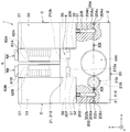
- the low-pressure side reservoir 217 is provided to store excess liquid refrigerant in the cycle.
- the low-pressure side reservoir 217 is provided for a portion of the compressor housing 20 that constitutes the suction flow path 202. More specifically, the low-pressure side reservoir 217 is provided between the refrigerant suction part 203 and the accommodation space 200 in the compressor housing 20.
- the low-pressure side reservoir 417 includes a bottomed hole 217a extending in the z direction and a closing plate 217b that closes the opening of the bottomed hole 217a.
- the bottomed hole 217a is formed with an upstream opening 217c through which the refrigerant from the refrigerant suction portion 203 flows and a downstream opening 217d through which the refrigerant stored inside flows out to the storage space 200 side.
- the downstream opening 217d is formed at a position closer to the closing plate 217b than the bottom surface of the bottomed hole 217a in the vertical direction so that the liquid refrigerant stored inside does not easily flow to the accommodation space 200 side.
- the upstream opening 217c is formed at a position equivalent to the downstream opening 217d in the vertical direction.
- a low-pressure side storage unit 217 capable of storing a liquid refrigerant is provided in an intake passage 202 formed in the compressor housing 20. If the low pressure side reservoir 417 is provided in the suction flow path 202 in this way, the low pressure side reservoir 217 can temporarily store excess liquid refrigerant in the cycle. Insufficient amount of refrigerant in the cycle can be avoided.
- the low-pressure side reservoir 217 has a structure in which the liquid refrigerant stored in the low-pressure side reservoir 217 does not easily flow to the accommodation space 200 side. According to this, it can suppress that a liquid refrigerant is compressed by the compression mechanism part 24 (namely, liquid back).
- the example in which the configuration in which the low-pressure side reservoir 217 is provided in the compressor housing 20 is applied to the configuration based on the refrigeration cycle apparatus 1 of the first embodiment has been described. It is not limited. The configuration in which the low pressure side reservoir 217 is provided in the compressor housing 20 can also be applied to the refrigeration cycle apparatus 1 of the embodiments other than the first embodiment.
- a storage space 218 for storing the low-pressure side storage section 219 is formed at a site constituting the suction flow path 202.
- the storage space 218 is formed by a bottomed hole 218a formed in the compressor housing 20 and a closing member 218b that closes the bottomed hole 218a.
- the bottomed hole 218a extends along the vertical direction.
- the low pressure side reservoir 219 is configured separately from the compressor housing 20.
- the low-pressure side reservoir 219 is formed of a bottomed cylindrical member capable of storing liquid refrigerant.
- the low-pressure side storage section 219 includes a bottomed cylindrical storage section 219 a and a connection section 219 b for connecting the storage section 219 a to the compressor housing 20.
- the reservoir 219a has an upper surface that is open, and the opening constitutes an upstream opening 219c through which the refrigerant from the refrigerant suction portion 203 flows. Further, a downstream opening 219e is formed with respect to the side wall 219d of the reservoir 219a to allow the refrigerant stored inside the reservoir 219a to flow out to the storage space 200 side. The downstream opening 219e is formed at a position closer to the upstream opening 219c than the bottom wall 219f of the reservoir 219a.
- the low-pressure side storage unit 219 is arranged in the storage space 218 so that the gas refrigerant sucked into the compression mechanism unit 24 flows between the bottomed hole 218a which is a wall surface forming the storage space 218. Specifically, in the low-pressure side reservoir 219, the reservoir 219a is separated from the bottomed hole 218a so that a refrigerant channel 218c through which a gas refrigerant flows is formed between the reservoir 219a and the bottomed hole 218a. ing.
- the refrigeration cycle apparatus 1 of the present embodiment has the same configuration as that of the fifth embodiment, and the effects obtained from the configuration common to the fifth embodiment can be obtained similarly to the fifth embodiment.
- the refrigeration cycle apparatus 1 of the present embodiment has a structure in which a low-temperature refrigerant sucked into the compression mechanism portion 24 flows between the low-pressure side storage portion 219 and the wall surface forming the storage space 218 inside the compressor housing 20. ing.
- This makes it difficult for the heat of the compressor housing 20 to be transmitted to the liquid refrigerant stored in the low-pressure side storage unit 219. That is, evaporation of the liquid refrigerant stored in the low-pressure side storage unit 219 can be suppressed by the heat of the compressor housing 20. Thereby, it is possible to avoid a shortage of the refrigerant amount in the cycle at the time of cycle load fluctuation.
- the refrigeration cycle apparatus 1 has a vertical structure in which a radiator 3, a decompression device 4, an evaporator 5, and a blower 6 are installed above a compressor 2. That is, in the refrigeration cycle apparatus 1 of the present embodiment, the radiator 3, the decompression device 4, the evaporator 5, and the blower 6 are arranged so as to overlap with the compressor 2 in the vertical direction (that is, the z direction).
- a cylindrical storage space 218 extending in the vertical direction (that is, the z direction) with respect to the compressor housing 20 is formed. Is done.
- a storage portion 219a extending in the vertical direction is stored.
- the refrigeration cycle apparatus 1 of the present embodiment has the same configuration as that of the sixth embodiment, and the effects obtained from the configuration common to the sixth embodiment can be obtained similarly to the seventh embodiment.
- the present embodiment is different from the first embodiment in that the decompression device 4 is configured by a capillary tube 43.
- the decompression device 4 is configured by a capillary tube 43.
- portions different from those in the first embodiment will be mainly described, and description of portions similar to those in the first embodiment may be omitted.
- the decompression device 4 includes a capillary tube 43.
- the capillary tube 43 is an elongated pipe that is disposed outside the compressor housing 20 and exhibits a pressure reducing action.
- the capillary tube 43 is provided with an upstream side connection portion 431 for directly connecting the high pressure outlet portion 32 of the radiator 3 so as not to be exposed to the outside at one end portion on the upstream side of the refrigerant flow.
- the capillary tube 43 is provided with a downstream connecting portion 432 for directly connecting the low pressure introduction portion 51 of the evaporator 5 so as not to be exposed to the outside at one end portion on the downstream side of the refrigerant flow.
- the high pressure outlet 32 of the radiator 3 is directly connected to one end of the capillary tube 43 that constitutes the decompression device 4 so as not to be exposed to the outside.
- the low-pressure introduction part 51 of the evaporator 5 is directly connected to the other end of the capillary tube 43 constituting the decompression device 4 so as not to be exposed to the outside. In this way, when the capillary tube 43 constituting the decompression device 4 is directly connected to the radiator 3 and the evaporator 5, the radiator 3, the decompression device 4, and the evaporator 5 are connected via the refrigerant pipe. Compared to, the number of parts is reduced. For this reason, simplification and size reduction of the refrigeration cycle apparatus 1 can be achieved.
- the specific arrangement form of the compressor 2, the radiator 3, the decompression device 4, the evaporator 5, and the blower 6 is exemplified, but the present invention is not limited to this.
- the arrangement form of the compressor 2, the radiator 3, the decompression device 4, and the evaporator 5 may be an arrangement form other than the above-described arrangement form.
- the example in which the internal housing portion 23 of the compressor 2 is connected to the main housing portion 21 via the buffer member 28 for damping the vibration of the compression mechanism portion 24 and the electric motor 25 has been described. It is not limited to.
- the compressor 2 may be configured such that the inner housing portion 23 is connected to the main housing portion 21 without the buffer member 28 interposed therebetween.
- the compression mechanism unit 24 of the compressor 2 is configured by a scroll-type compression mechanism unit, but the present invention is not limited to this.
- the compression mechanism unit 24 may be constituted by, for example, a reciprocating type compression mechanism unit or a rolling piston type compression mechanism unit.
- the electric motor 25 of the compressor 2 is configured by the outer rotor motor has been described, but the present invention is not limited to this.
- the electric motor 25 may be composed of, for example, an inner rotor motor.
- the compressor 2 is configured by an electric compressor in which the electric motor 25 drives the compression mechanism unit 24 has been described, but the present invention is not limited to this.
- the compressor 2 may be comprised by what drives the compression mechanism part 24 using an internal combustion engine, for example.
- the radiator 3 is configured by the heat exchanger including the plurality of tubes 34, the fins 35, the first high-pressure tank 36, and the second high-pressure tank 37 has been described, but is not limited thereto.
- the radiator 3 may be configured by, for example, a tankless heat exchanger including a tube bent in a serpentine shape and a plate fin.
- the decompression device 4 may be constituted by, for example, a variable throttle type expansion valve capable of changing the throttle opening.
- the example in which the evaporator 5 is configured by the heat exchanger including the plurality of tubes 54, the fins 55, the first low-pressure tank 56, and the second low-pressure tank 57 has been described, but is not limited thereto.
- the evaporator 5 may be composed of, for example, a tankless heat exchanger including a tube bent in a serpentine shape and a plate fin.
- blower 6 may be configured such that the hot air fan 62A and the cold air fan 62B are driven by a single fan motor.
- the refrigeration cycle apparatus 1 of the present disclosure is not limited to an air conditioner mounted on a vehicle, but can be widely applied to, for example, an indoor air conditioner such as a house, and a device temperature controller.
- the refrigeration cycle apparatus includes a refrigerant discharge portion in which a high pressure introduction portion of a radiator is directly connected to a compressor housing, and a low pressure of an evaporator.
- a refrigerant suction part to which the outlet part is directly connected is provided.
- the compressor housing of the refrigeration cycle apparatus is provided with a low-pressure side reservoir that can store liquid refrigerant in an intake passage extending from the refrigerant intake to the compression mechanism.
- the radiator and evaporator are connected directly to the compressor housing (that is, a pipe-less structure), the refrigerant charge amount in the cycle is reduced due to the absence of refrigerant piping, and the cycle is subject to fluctuations in the cycle load. There is a concern that the amount of refrigerant will be insufficient.
- the liquid refrigerant that is excessive in the cycle can be temporarily stored in the low pressure side reservoir, so that when the cycle load fluctuates, Insufficient amount of refrigerant in the cycle can be avoided.
- the compressor housing of the refrigeration cycle apparatus has a storage space for storing the low-pressure side storage section in the suction flow path.
- the low-pressure side storage part is comprised with a bottomed cylindrical member, and is arrange
- the temperature of the compressor housing is likely to be increased by receiving heat from the refrigerant compressed by the compression mechanism. For this reason, if the low-pressure side reservoir is simply provided for the compressor housing, the liquid refrigerant stored in the low-pressure side reservoir may evaporate due to the heat of the compressor housing.
- the refrigerant is stored in the low-pressure side reservoir. It becomes difficult for the heat of the compressor housing to be transferred to the liquid refrigerant. That is, the evaporation of the liquid refrigerant stored in the low-pressure side storage unit due to the heat of the compressor housing can be suppressed. Thereby, since the liquid refrigerant is appropriately stored in the low-pressure side storage section, it is possible to avoid a shortage of the refrigerant amount in the cycle when the load of the cycle changes.
- the radiator of the refrigeration cycle apparatus has a high-pressure derivation unit for deriving the refrigerant that has passed through the refrigeration cycle apparatus to the decompression device side.
- the evaporator has a low pressure introduction part for introducing the refrigerant decompressed by the decompression device.
- the decompression device is provided inside the compressor housing.
- the compressor housing is provided with an intermediate introduction portion that guides the refrigerant that has passed through the radiator to the decompression device and an intermediate lead-out portion that guides the refrigerant that has passed through the decompression device to the evaporator.
- the high pressure lead-out part is directly connected to the intermediate introduction part so as not to be exposed to the outside.
- the low pressure introduction part is directly connected to the intermediate lead-out part so as not to be exposed to the outside.
- the decompression device is provided inside the compressor housing in this way, the refrigeration cycle apparatus can be simplified compared to the case where a separate decompression device is installed outside the compressor housing.
- the refrigeration cycle apparatus of the present disclosure has a structure in which a portion of the compressor housing that constitutes the decompression device is directly connected to the radiator and the evaporator.
- the refrigeration cycle apparatus can be simplified and downsized. .
- the decompression device of the refrigeration cycle apparatus is composed of a fixed throttle formed in a through hole inside the compressor housing. If the decompression device is configured with a fixed throttle formed in the compressor housing in this way, the number of parts is reduced compared to the case where the decompression device is configured to include a variable throttle mechanism, and thus the refrigeration cycle apparatus is simplified In addition, the size can be reduced.
- the refrigerant flow path from the refrigerant suction portion to the refrigerant discharge portion via the compression mechanism portion and the intermediate introduction portion to the intermediate lead-out portion via the decompression device are provided.
- a heat exchange suppression unit is provided for thermally dividing the refrigerant flow path that reaches.
- the decompression device is simply formed inside the compressor housing, unnecessary heat exchange may occur between the refrigerant flowing through the decompression device and the refrigerant sucked into the compression mechanism and the refrigerant discharged from the compression mechanism. Is done.
- a heat exchange suppression unit for thermally dividing the refrigerant flow path from the refrigerant suction section to the refrigerant discharge section and the refrigerant flow path from the intermediate introduction section to the intermediate discharge section with respect to the compressor housing. If it is set as the structure provided, the unnecessary heat exchange mentioned above can be suppressed.
- high-pressure side storage capable of storing liquid refrigerant between the intermediate introduction part and the decompression device in the refrigerant flow path from the intermediate introduction part to the intermediate outlet part.
- the liquid refrigerant that is excessive in the cycle can be temporarily stored in the high pressure side reservoir, so that the cycle can be changed when the cycle load changes. It is possible to avoid a shortage of the refrigerant amount inside.
- the high-pressure side reservoir of the refrigeration cycle apparatus has an upstream opening that allows the refrigerant from the intermediate introduction portion to flow therein, and a downstream side that causes the refrigerant stored therein to flow out to the decompression device side.
- An opening is formed.
- the downstream opening is formed on the lower side in the vertical direction than the upstream opening.
- the liquid refrigerant stored in the high-pressure side storage section can easily flow to the decompression mechanism side. That is, a liquid refrigerant having a small enthalpy easily flows to the decompression device side. As a result, the difference in enthalpy before and after the evaporator can be secured, and the heat absorption capability of the evaporator can be improved.
- the “vertical direction” means a direction perpendicular to the horizontal plane, and can be interpreted to mean a direction in which gravity acts.
- the radiator of the refrigeration cycle apparatus has a high-pressure deriving unit for deriving the refrigerant that has passed through the radiator to the decompression device side.
- the evaporator has a low pressure introduction part for introducing the refrigerant decompressed by the decompression device.
- the decompression device is disposed outside the compressor housing, and includes a valve body that forms an outer shell, and a throttle mechanism that is provided inside the valve body.
- the valve body is provided with a valve introduction part that guides the refrigerant that has passed through the radiator to the throttle mechanism part, and a valve lead-out part that guides the refrigerant that has passed through the throttle mechanism part to the evaporator.
- the high pressure lead-out portion is directly connected to the valve introduction portion so as not to be exposed to the outside.
- the low-pressure introduction part is directly connected to the valve lead-out part so as not to be exposed to the outside.
- the refrigeration cycle apparatus includes a refrigerant flow path extending from the refrigerant suction section to the refrigerant discharge section and a refrigerant flow path extending from the valve introduction section to the valve discharge section between the valve body and the compressor housing.
- a heat exchange suppression unit for thermally dividing is provided.
- the refrigerant flow path from the refrigerant suction section to the refrigerant discharge section and the refrigerant flow path from the intermediate introduction section to the intermediate outlet section are thermally separated. If it is set as the structure which provides a heat exchange suppression part, the unnecessary heat exchange mentioned above can be suppressed.
- liquid refrigerant that is excessive in the cycle is placed between the valve introduction part and the throttle mechanism part in the refrigerant flow path from the intermediate introduction part to the intermediate lead-out part in the valve body of the refrigeration cycle apparatus.
- a high-pressure side reservoir for storing is formed.
- the liquid refrigerant that is excessive in the cycle can be temporarily stored in the high-pressure side reservoir, so that the cycle time can be changed when the load of the cycle changes. Insufficient amount of refrigerant can be avoided.
- the high-pressure side storage section of the refrigeration cycle apparatus includes an upstream opening that allows the refrigerant from the valve introduction section to flow therein, and a downstream side that discharges the refrigerant stored therein to the throttle mechanism section.
- An opening is formed.
- the downstream opening is formed on the lower side in the vertical direction than the upstream opening.
- the liquid refrigerant stored in the high-pressure side storage section can easily flow to the decompression mechanism side. That is, a liquid refrigerant having a small enthalpy easily flows to the decompression device side. As a result, the difference in enthalpy before and after the evaporator can be secured, and the heat absorption capability of the evaporator can be improved.
- the radiator of the refrigeration cycle apparatus has a high-pressure derivation unit for deriving the refrigerant that has passed through the refrigeration cycle apparatus to the decompression device side.
- the evaporator has a low pressure introduction part for introducing the refrigerant decompressed by the decompression device.
- the decompression device is composed of a capillary tube that is disposed outside the compressor housing and exerts a decompression action.
- the high-pressure outlet is directly connected to one end of the capillary tube so as not to be exposed to the outside.
- the low pressure introduction part is directly connected to the other end of the capillary tube so as not to be exposed to the outside.
- the refrigeration cycle apparatus can be simplified and downsized.
- the compressor housing of the refrigeration cycle apparatus includes an outer shell forming portion that forms an outer shell, and a support member that supports the compression mechanism portion.
- the outer shell forming part is provided with at least a refrigerant discharge part and a refrigerant suction part.
- the support member is connected with the outer shell formation part via the buffer member for attenuating the vibration of a compression mechanism part.
- the vibration generated in the compression mechanism part is attenuated by the buffer member, so that the vibration of the compression mechanism part is hardly transmitted to the outer shell forming part of the compressor housing.
- the vibration of the outer shell forming portion is suppressed, the stress applied to the connecting portion of the compressor housing, the radiator and the evaporator can be suppressed, so that the durability of the refrigeration cycle apparatus can be ensured.
Landscapes
- Engineering & Computer Science (AREA)
- Mechanical Engineering (AREA)
- General Engineering & Computer Science (AREA)
- Physics & Mathematics (AREA)
- Thermal Sciences (AREA)
- Applications Or Details Of Rotary Compressors (AREA)
- Compressor (AREA)
Applications Claiming Priority (2)
| Application Number | Priority Date | Filing Date | Title |
|---|---|---|---|
| JP2018-093091 | 2018-05-14 | ||
| JP2018093091A JP7099042B2 (ja) | 2018-05-14 | 2018-05-14 | 冷凍サイクル装置 |
Publications (1)
| Publication Number | Publication Date |
|---|---|
| WO2019220923A1 true WO2019220923A1 (ja) | 2019-11-21 |
Family
ID=68539925
Family Applications (1)
| Application Number | Title | Priority Date | Filing Date |
|---|---|---|---|
| PCT/JP2019/017772 Ceased WO2019220923A1 (ja) | 2018-05-14 | 2019-04-25 | 冷凍サイクル装置 |
Country Status (2)
| Country | Link |
|---|---|
| JP (1) | JP7099042B2 (enExample) |
| WO (1) | WO2019220923A1 (enExample) |
Cited By (10)
| Publication number | Priority date | Publication date | Assignee | Title |
|---|---|---|---|---|
| WO2022202306A1 (ja) * | 2021-03-25 | 2022-09-29 | 株式会社デンソー | 冷凍サイクル装置 |
| EP4166866A1 (en) * | 2021-10-15 | 2023-04-19 | Hamilton Sundstrand Corporation | Integrated supplemental cooling unit |
| WO2023188888A1 (ja) * | 2022-03-30 | 2023-10-05 | 株式会社豊田自動織機 | 移動体用空調装置 |
| WO2023188887A1 (ja) * | 2022-03-30 | 2023-10-05 | 株式会社豊田自動織機 | 移動体用ヒートポンプ装置 |
| WO2023188883A1 (ja) * | 2022-03-30 | 2023-10-05 | 株式会社豊田自動織機 | 移動体用ヒートポンプ装置 |
| WO2023188884A1 (ja) * | 2022-03-30 | 2023-10-05 | 株式会社豊田自動織機 | 移動体用ヒートポンプ装置 |
| WO2023188882A1 (ja) * | 2022-03-30 | 2023-10-05 | 株式会社豊田自動織機 | 移動体用ヒートポンプ装置 |
| DE102022213574A1 (de) * | 2022-10-10 | 2024-04-11 | Vertiv Srl | Wärmepumpe mit schwingungsbeeinflussungseinrichtung |
| WO2024085066A1 (ja) * | 2022-10-21 | 2024-04-25 | 株式会社デンソー | 電動圧縮機 |
| EP4631753A1 (de) * | 2024-04-09 | 2025-10-15 | OET GmbH | Klimatisierungssystem für ein fahrzeug |
Citations (9)
| Publication number | Priority date | Publication date | Assignee | Title |
|---|---|---|---|---|
| JPS539934Y2 (enExample) * | 1973-08-06 | 1978-03-16 | ||
| JPS57167376U (enExample) * | 1981-04-15 | 1982-10-21 | ||
| JPH0554025B2 (enExample) * | 1984-11-22 | 1993-08-11 | Hitachi Ltd | |
| JPH07151399A (ja) * | 1993-11-30 | 1995-06-13 | Sanyo Electric Co Ltd | 冷媒回路 |
| JPH08108739A (ja) * | 1994-10-07 | 1996-04-30 | Nippondenso Co Ltd | 車両用空気調和装置 |
| JPH11277167A (ja) * | 1998-03-25 | 1999-10-12 | Showa Alum Corp | ロールボンドパネル及びその製造方法 |
| JP2013203099A (ja) * | 2012-03-27 | 2013-10-07 | Panasonic Corp | 車両用空調装置および圧縮装置 |
| JP2014035176A (ja) * | 2012-08-10 | 2014-02-24 | Calsonic Kansei Corp | 熱交換器の固定構造 |
| JP2014152703A (ja) * | 2013-02-08 | 2014-08-25 | Kobe Steel Ltd | 圧縮装置 |
Family Cites Families (1)
| Publication number | Priority date | Publication date | Assignee | Title |
|---|---|---|---|---|
| JP5034512B2 (ja) | 2007-01-23 | 2012-09-26 | パナソニック株式会社 | 一体型空気調和機 |
-
2018
- 2018-05-14 JP JP2018093091A patent/JP7099042B2/ja active Active
-
2019
- 2019-04-25 WO PCT/JP2019/017772 patent/WO2019220923A1/ja not_active Ceased
Patent Citations (9)
| Publication number | Priority date | Publication date | Assignee | Title |
|---|---|---|---|---|
| JPS539934Y2 (enExample) * | 1973-08-06 | 1978-03-16 | ||
| JPS57167376U (enExample) * | 1981-04-15 | 1982-10-21 | ||
| JPH0554025B2 (enExample) * | 1984-11-22 | 1993-08-11 | Hitachi Ltd | |
| JPH07151399A (ja) * | 1993-11-30 | 1995-06-13 | Sanyo Electric Co Ltd | 冷媒回路 |
| JPH08108739A (ja) * | 1994-10-07 | 1996-04-30 | Nippondenso Co Ltd | 車両用空気調和装置 |
| JPH11277167A (ja) * | 1998-03-25 | 1999-10-12 | Showa Alum Corp | ロールボンドパネル及びその製造方法 |
| JP2013203099A (ja) * | 2012-03-27 | 2013-10-07 | Panasonic Corp | 車両用空調装置および圧縮装置 |
| JP2014035176A (ja) * | 2012-08-10 | 2014-02-24 | Calsonic Kansei Corp | 熱交換器の固定構造 |
| JP2014152703A (ja) * | 2013-02-08 | 2014-08-25 | Kobe Steel Ltd | 圧縮装置 |
Cited By (11)
| Publication number | Priority date | Publication date | Assignee | Title |
|---|---|---|---|---|
| WO2022202306A1 (ja) * | 2021-03-25 | 2022-09-29 | 株式会社デンソー | 冷凍サイクル装置 |
| EP4166866A1 (en) * | 2021-10-15 | 2023-04-19 | Hamilton Sundstrand Corporation | Integrated supplemental cooling unit |
| WO2023188888A1 (ja) * | 2022-03-30 | 2023-10-05 | 株式会社豊田自動織機 | 移動体用空調装置 |
| WO2023188887A1 (ja) * | 2022-03-30 | 2023-10-05 | 株式会社豊田自動織機 | 移動体用ヒートポンプ装置 |
| WO2023188883A1 (ja) * | 2022-03-30 | 2023-10-05 | 株式会社豊田自動織機 | 移動体用ヒートポンプ装置 |
| WO2023188884A1 (ja) * | 2022-03-30 | 2023-10-05 | 株式会社豊田自動織機 | 移動体用ヒートポンプ装置 |
| WO2023188882A1 (ja) * | 2022-03-30 | 2023-10-05 | 株式会社豊田自動織機 | 移動体用ヒートポンプ装置 |
| DE102022213574A1 (de) * | 2022-10-10 | 2024-04-11 | Vertiv Srl | Wärmepumpe mit schwingungsbeeinflussungseinrichtung |
| DE102022213574B4 (de) | 2022-10-10 | 2025-03-13 | Vertiv Srl | Wärmepumpe mit schwingungsbeeinflussungseinrichtung |
| WO2024085066A1 (ja) * | 2022-10-21 | 2024-04-25 | 株式会社デンソー | 電動圧縮機 |
| EP4631753A1 (de) * | 2024-04-09 | 2025-10-15 | OET GmbH | Klimatisierungssystem für ein fahrzeug |
Also Published As
| Publication number | Publication date |
|---|---|
| JP2019199975A (ja) | 2019-11-21 |
| JP7099042B2 (ja) | 2022-07-12 |
Similar Documents
| Publication | Publication Date | Title |
|---|---|---|
| WO2019220923A1 (ja) | 冷凍サイクル装置 | |
| KR100944147B1 (ko) | 증기 분사 시스템을 가진 스크롤 압축기 | |
| US11506201B2 (en) | Scroll compressor having intermediate pressure chamber to supply fluid to compression chambers via two supply passages and two injection ports to limit reduction in compression efficiency | |
| KR102443952B1 (ko) | 전동 압축기 | |
| CN105864049A (zh) | 密闭型压缩机 | |
| JP2008169816A (ja) | 圧縮機 | |
| WO2016206054A1 (zh) | 旋转压缩机及具有其的冷冻循环装置 | |
| WO2022153364A1 (ja) | ロータリー型ヒートポンプおよびこれが搭載されたエアコンおよび自動車 | |
| JP2007224809A (ja) | 電動圧縮機 | |
| JP6204867B2 (ja) | 電動圧縮機 | |
| WO2012090345A1 (ja) | 冷媒圧縮機 | |
| CN110382963A (zh) | 冷冻装置 | |
| US12338807B2 (en) | Reciprocating compressor | |
| JP6271246B2 (ja) | シリンダ回転型圧縮機 | |
| WO2006106753A1 (ja) | スクロール型流体機械 | |
| CN205315275U (zh) | 密闭型压缩机 | |
| WO2020059096A1 (ja) | ロータリコンプレッサおよび冷凍サイクル装置 | |
| WO2019220924A1 (ja) | 電動圧縮機 | |
| JP2023060670A (ja) | 軸封構造、圧縮機および冷凍装置 | |
| JP7260804B2 (ja) | 冷媒導入管を有する圧縮機 | |
| JP6772934B2 (ja) | 電動圧縮機 | |
| JP7206929B2 (ja) | 電動圧縮機 | |
| JP2013253541A (ja) | 二段圧縮機 | |
| JP4606272B2 (ja) | 冷却システムの電動圧縮機 | |
| JP2023006134A (ja) | 均油座を有する圧縮機 |
Legal Events
| Date | Code | Title | Description |
|---|---|---|---|
| 121 | Ep: the epo has been informed by wipo that ep was designated in this application |
Ref document number: 19803418 Country of ref document: EP Kind code of ref document: A1 |
|
| NENP | Non-entry into the national phase |
Ref country code: DE |
|
| 122 | Ep: pct application non-entry in european phase |
Ref document number: 19803418 Country of ref document: EP Kind code of ref document: A1 |