WO2019220716A1 - Dispositif d'attaque de charge - Google Patents
Dispositif d'attaque de charge Download PDFInfo
- Publication number
- WO2019220716A1 WO2019220716A1 PCT/JP2019/005219 JP2019005219W WO2019220716A1 WO 2019220716 A1 WO2019220716 A1 WO 2019220716A1 JP 2019005219 W JP2019005219 W JP 2019005219W WO 2019220716 A1 WO2019220716 A1 WO 2019220716A1
- Authority
- WO
- WIPO (PCT)
- Prior art keywords
- circuit
- voltage
- diagnosis
- current
- current detection
- Prior art date
Links
Images


Classifications
-
- G—PHYSICS
- G01—MEASURING; TESTING
- G01R—MEASURING ELECTRIC VARIABLES; MEASURING MAGNETIC VARIABLES
- G01R31/00—Arrangements for testing electric properties; Arrangements for locating electric faults; Arrangements for electrical testing characterised by what is being tested not provided for elsewhere
- G01R31/50—Testing of electric apparatus, lines, cables or components for short-circuits, continuity, leakage current or incorrect line connections
-
- G—PHYSICS
- G01—MEASURING; TESTING
- G01R—MEASURING ELECTRIC VARIABLES; MEASURING MAGNETIC VARIABLES
- G01R31/00—Arrangements for testing electric properties; Arrangements for locating electric faults; Arrangements for electrical testing characterised by what is being tested not provided for elsewhere
- G01R31/40—Testing power supplies
-
- B—PERFORMING OPERATIONS; TRANSPORTING
- B60—VEHICLES IN GENERAL
- B60W—CONJOINT CONTROL OF VEHICLE SUB-UNITS OF DIFFERENT TYPE OR DIFFERENT FUNCTION; CONTROL SYSTEMS SPECIALLY ADAPTED FOR HYBRID VEHICLES; ROAD VEHICLE DRIVE CONTROL SYSTEMS FOR PURPOSES NOT RELATED TO THE CONTROL OF A PARTICULAR SUB-UNIT
- B60W20/00—Control systems specially adapted for hybrid vehicles
- B60W20/50—Control strategies for responding to system failures, e.g. for fault diagnosis, failsafe operation or limp mode
-
- B—PERFORMING OPERATIONS; TRANSPORTING
- B60—VEHICLES IN GENERAL
- B60W—CONJOINT CONTROL OF VEHICLE SUB-UNITS OF DIFFERENT TYPE OR DIFFERENT FUNCTION; CONTROL SYSTEMS SPECIALLY ADAPTED FOR HYBRID VEHICLES; ROAD VEHICLE DRIVE CONTROL SYSTEMS FOR PURPOSES NOT RELATED TO THE CONTROL OF A PARTICULAR SUB-UNIT
- B60W50/00—Details of control systems for road vehicle drive control not related to the control of a particular sub-unit, e.g. process diagnostic or vehicle driver interfaces
- B60W50/02—Ensuring safety in case of control system failures, e.g. by diagnosing, circumventing or fixing failures
- B60W50/0205—Diagnosing or detecting failures; Failure detection models
-
- H—ELECTRICITY
- H02—GENERATION; CONVERSION OR DISTRIBUTION OF ELECTRIC POWER
- H02H—EMERGENCY PROTECTIVE CIRCUIT ARRANGEMENTS
- H02H3/00—Emergency protective circuit arrangements for automatic disconnection directly responsive to an undesired change from normal electric working condition with or without subsequent reconnection ; integrated protection
-
- H—ELECTRICITY
- H02—GENERATION; CONVERSION OR DISTRIBUTION OF ELECTRIC POWER
- H02M—APPARATUS FOR CONVERSION BETWEEN AC AND AC, BETWEEN AC AND DC, OR BETWEEN DC AND DC, AND FOR USE WITH MAINS OR SIMILAR POWER SUPPLY SYSTEMS; CONVERSION OF DC OR AC INPUT POWER INTO SURGE OUTPUT POWER; CONTROL OR REGULATION THEREOF
- H02M1/00—Details of apparatus for conversion
- H02M1/32—Means for protecting converters other than automatic disconnection
-
- H—ELECTRICITY
- H02—GENERATION; CONVERSION OR DISTRIBUTION OF ELECTRIC POWER
- H02M—APPARATUS FOR CONVERSION BETWEEN AC AND AC, BETWEEN AC AND DC, OR BETWEEN DC AND DC, AND FOR USE WITH MAINS OR SIMILAR POWER SUPPLY SYSTEMS; CONVERSION OF DC OR AC INPUT POWER INTO SURGE OUTPUT POWER; CONTROL OR REGULATION THEREOF
- H02M3/00—Conversion of dc power input into dc power output
- H02M3/02—Conversion of dc power input into dc power output without intermediate conversion into ac
- H02M3/04—Conversion of dc power input into dc power output without intermediate conversion into ac by static converters
- H02M3/10—Conversion of dc power input into dc power output without intermediate conversion into ac by static converters using discharge tubes with control electrode or semiconductor devices with control electrode
- H02M3/145—Conversion of dc power input into dc power output without intermediate conversion into ac by static converters using discharge tubes with control electrode or semiconductor devices with control electrode using devices of a triode or transistor type requiring continuous application of a control signal
- H02M3/155—Conversion of dc power input into dc power output without intermediate conversion into ac by static converters using discharge tubes with control electrode or semiconductor devices with control electrode using devices of a triode or transistor type requiring continuous application of a control signal using semiconductor devices only
- H02M3/156—Conversion of dc power input into dc power output without intermediate conversion into ac by static converters using discharge tubes with control electrode or semiconductor devices with control electrode using devices of a triode or transistor type requiring continuous application of a control signal using semiconductor devices only with automatic control of output voltage or current, e.g. switching regulators
- H02M3/158—Conversion of dc power input into dc power output without intermediate conversion into ac by static converters using discharge tubes with control electrode or semiconductor devices with control electrode using devices of a triode or transistor type requiring continuous application of a control signal using semiconductor devices only with automatic control of output voltage or current, e.g. switching regulators including plural semiconductor devices as final control devices for a single load
- H02M3/1588—Conversion of dc power input into dc power output without intermediate conversion into ac by static converters using discharge tubes with control electrode or semiconductor devices with control electrode using devices of a triode or transistor type requiring continuous application of a control signal using semiconductor devices only with automatic control of output voltage or current, e.g. switching regulators including plural semiconductor devices as final control devices for a single load comprising at least one synchronous rectifier element
-
- H—ELECTRICITY
- H02—GENERATION; CONVERSION OR DISTRIBUTION OF ELECTRIC POWER
- H02P—CONTROL OR REGULATION OF ELECTRIC MOTORS, ELECTRIC GENERATORS OR DYNAMO-ELECTRIC CONVERTERS; CONTROLLING TRANSFORMERS, REACTORS OR CHOKE COILS
- H02P29/00—Arrangements for regulating or controlling electric motors, appropriate for both AC and DC motors
- H02P29/02—Providing protection against overload without automatic interruption of supply
- H02P29/024—Detecting a fault condition, e.g. short circuit, locked rotor, open circuit or loss of load
-
- H—ELECTRICITY
- H02—GENERATION; CONVERSION OR DISTRIBUTION OF ELECTRIC POWER
- H02P—CONTROL OR REGULATION OF ELECTRIC MOTORS, ELECTRIC GENERATORS OR DYNAMO-ELECTRIC CONVERTERS; CONTROLLING TRANSFORMERS, REACTORS OR CHOKE COILS
- H02P7/00—Arrangements for regulating or controlling the speed or torque of electric DC motors
- H02P7/06—Arrangements for regulating or controlling the speed or torque of electric DC motors for regulating or controlling an individual dc dynamo-electric motor by varying field or armature current
- H02P7/18—Arrangements for regulating or controlling the speed or torque of electric DC motors for regulating or controlling an individual dc dynamo-electric motor by varying field or armature current by master control with auxiliary power
- H02P7/24—Arrangements for regulating or controlling the speed or torque of electric DC motors for regulating or controlling an individual dc dynamo-electric motor by varying field or armature current by master control with auxiliary power using discharge tubes or semiconductor devices
- H02P7/28—Arrangements for regulating or controlling the speed or torque of electric DC motors for regulating or controlling an individual dc dynamo-electric motor by varying field or armature current by master control with auxiliary power using discharge tubes or semiconductor devices using semiconductor devices
- H02P7/285—Arrangements for regulating or controlling the speed or torque of electric DC motors for regulating or controlling an individual dc dynamo-electric motor by varying field or armature current by master control with auxiliary power using discharge tubes or semiconductor devices using semiconductor devices controlling armature supply only
- H02P7/29—Arrangements for regulating or controlling the speed or torque of electric DC motors for regulating or controlling an individual dc dynamo-electric motor by varying field or armature current by master control with auxiliary power using discharge tubes or semiconductor devices using semiconductor devices controlling armature supply only using pulse modulation
-
- B—PERFORMING OPERATIONS; TRANSPORTING
- B60—VEHICLES IN GENERAL
- B60W—CONJOINT CONTROL OF VEHICLE SUB-UNITS OF DIFFERENT TYPE OR DIFFERENT FUNCTION; CONTROL SYSTEMS SPECIALLY ADAPTED FOR HYBRID VEHICLES; ROAD VEHICLE DRIVE CONTROL SYSTEMS FOR PURPOSES NOT RELATED TO THE CONTROL OF A PARTICULAR SUB-UNIT
- B60W50/00—Details of control systems for road vehicle drive control not related to the control of a particular sub-unit, e.g. process diagnostic or vehicle driver interfaces
- B60W50/02—Ensuring safety in case of control system failures, e.g. by diagnosing, circumventing or fixing failures
- B60W50/0205—Diagnosing or detecting failures; Failure detection models
- B60W2050/021—Means for detecting failure or malfunction
-
- Y—GENERAL TAGGING OF NEW TECHNOLOGICAL DEVELOPMENTS; GENERAL TAGGING OF CROSS-SECTIONAL TECHNOLOGIES SPANNING OVER SEVERAL SECTIONS OF THE IPC; TECHNICAL SUBJECTS COVERED BY FORMER USPC CROSS-REFERENCE ART COLLECTIONS [XRACs] AND DIGESTS
- Y02—TECHNOLOGIES OR APPLICATIONS FOR MITIGATION OR ADAPTATION AGAINST CLIMATE CHANGE
- Y02B—CLIMATE CHANGE MITIGATION TECHNOLOGIES RELATED TO BUILDINGS, e.g. HOUSING, HOUSE APPLIANCES OR RELATED END-USER APPLICATIONS
- Y02B70/00—Technologies for an efficient end-user side electric power management and consumption
- Y02B70/10—Technologies improving the efficiency by using switched-mode power supplies [SMPS], i.e. efficient power electronics conversion e.g. power factor correction or reduction of losses in power supplies or efficient standby modes
Definitions
- the present invention relates to a load driving device including a synchronous rectification circuit.
- the current flowing through the synchronous rectifier circuit may be less than the accuracy of current detection, and in this case, there is a risk of erroneous detection as a disconnection.
- the drive side switching element is turned on / off while the return side switching element is in the OFF state, and the presence / absence of the output voltage pulse is detected to determine the disconnection.
- the synchronous rectification operation is stopped for a fixed time every fixed period, pulse driving is performed with a fixed duty by the driving switching element during the stop period, and the output terminal of the driving switching element is connected. It is described that the disconnection is determined depending on whether or not a pulse voltage signal is output.
- a load driving device includes a synchronous rectification circuit having a driving side switching element and a return side switching element, a driver control circuit for controlling the synchronous rectification circuit, and a voltage monitor for monitoring a voltage at an output terminal of the synchronous rectification circuit.
- the driver control circuit when receiving a diagnostic command, controls so that both the return-side switching elements are turned OFF when the drive-side switching elements are switched from ON to OFF, and the voltage monitor circuit Detects a normal state when the voltage to be monitored is within a predetermined voltage range during a period in which both the drive side switching element and the return side switching element are OFF.
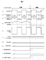
- the driver control circuit 108 turns on / off the high-side FET 102 and the low-side FET 103 by controlling the respective gate voltages in accordance with the input PWM command.
- the current detection circuit 109 detects the current flowing through the synchronous rectification circuit 104 and inputs the detection result to the diagnosis necessity determination circuit 110.
- the diagnosis necessity determination circuit 110 compares the duty ratio of the PWM control input from the microcomputer or the like and the current detection result of the current detection circuit 109 with a threshold value, and ORs the disconnection diagnosis result A based on the comparison result.
- a diagnostic command is output to the driver control circuit 108 to the gate 112.
- the driver control circuit 108 detects that the diagnosis command has become H (High)
- the driver control circuit 108 shifts to a diagnosis mode, which will be described later, and outputs a diagnosis signal H to the voltage monitor circuit 111 during the diagnosis mode.
- the diagnosis necessity determination circuit 110 when the duty ratio is higher than the duty ratio threshold, the state of the synchronous rectifier circuit output terminal 105 is based only on the current detection result of the current detection circuit 109 shown in FIG. The determination is made by the diagnosis necessity determination circuit 110. Therefore, the diagnosis necessity determination circuit 110 always sets the diagnosis command shown in FIG.
- the diagnosis necessity determination circuit 110 When the current detection result of the current detection circuit 109 is larger than the current threshold, the diagnosis necessity determination circuit 110 outputs L as the disconnection diagnosis result A as shown in FIG. 2 (i). On the other hand, if the current detection result of the current detection circuit 109 is smaller than the current threshold at time t1, the disconnection diagnosis result A shown in FIG. As a result, as shown in FIG. 2 (k), the OR gate 112 outputs the disconnection diagnosis result C as H in the disconnection state.
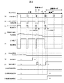
- FIG. 3 is a timing chart showing an example of the operation when the duty ratio is low in this embodiment. Specifically, this is an example when the duty ratio is equal to or less than the duty ratio threshold.
- the diagnosis necessity determination circuit 110 is shown when the current detection result of the current detection circuit 109 shown in FIG. 3D is equal to or less than the current threshold and the duty ratio shown in FIG. 3F is equal to or less than the duty ratio threshold. As shown in 3 (g), the diagnosis command is set to H. In other cases, the diagnosis necessity determination circuit 110 outputs a diagnosis command as L to the driver control circuit 108 as shown in FIG.
- the voltage of the synchronous rectifier circuit output terminal 105 during the diagnosis mode rises to the power supply voltage VB to which the load 106 is connected.
- the voltage monitor circuit 111 compares the voltage of the synchronous rectifier circuit output terminal 105 during the diagnosis mode with a voltage threshold value. Then, as shown in FIG. 3E, the state where the voltage of the synchronous rectifier circuit output terminal 105 is higher than the voltage threshold value continues for a predetermined filter time T, that is, the voltage monitor circuit 111 is connected to the synchronous rectifier circuit output terminal.
- the voltage monitor circuit 111 detects a normal state
- the voltage monitor circuit 111 transmits a signal indicating a normal state (L of the disconnection diagnosis result B) to the driver control circuit 108
- the driver control circuit 108 indicates a signal indicating a normal operation
- L the ON / OFF operation of the high-side FET 102 that is the return-side switching element and the low-side FET 103 that is the drive-side switching element
- the diagnostic mode shifts to the timing at which the low-side FET 103, which is the driving side switching element, switches from ON to OFF.
- both the high-side FET 102 and the low-side FET 103 are in the OFF state.
- a reflux current flows through the body diode of the high-side FET 102.
- the resistance increases compared to the normal drive in which the high-side FET 102 is turned on during the return, the longer the return current flows through the diode, the more heat is generated, which affects the behavior of the load 106. There is a risk.
- the filter time T is set to prevent misdiagnosis due to noise and the like, and the diagnosis is performed more reliably.
- the voltage monitor circuit 111 is normal when the output voltage exceeds the voltage threshold without providing the filter time T. It is also possible to detect the state. In this case, the detection of the normal state is completed in a very short period, and the increase in heat generation and the influence on the behavior of the load 106 can be minimized.
- the driver control circuit 108 shifts to the diagnostic mode at the Fall edge t4 of the PWM command shown in FIG. 3A, and turns off both the high-side FET 102 and the low-side FET 103. To do.
- the voltage of the synchronous rectifier circuit output terminal 105 in the diagnosis mode maintains the voltage value when the low-side FET 103 immediately before the shift to the diagnosis mode is ON. Therefore, as shown in FIG. It becomes a potential.
- the diagnostic mode is shifted to the timing when the low-side FET 103 which is the driving side switching element is switched from ON to OFF. This is because if the diagnosis is performed by turning off both FETs at the timing when the high-side FET 102 is switched from ON to OFF, the voltage at the synchronous rectifier circuit output terminal 105 is in the normal state and the disconnection state. This is because both become voltages close to the power supply voltage VB, making it difficult to distinguish between normal and disconnected. In order to avoid such a situation, in this embodiment, the diagnosis is performed when the low-side FET 103 is switched from ON to OFF so that the power supply voltage VB is obtained in the normal state, and the GND is established in the case of the disconnection. Diagnosis is performed at the timing that can be set to voltage, making it easy to distinguish between disconnection and normal.
- the disconnection diagnosis during the diagnosis mode performed with both the high-side FET 102 and the low-side FET 103 turned off is based on the voltage value of the synchronous rectifier circuit output terminal 105 and the disconnection state of the synchronous rectifier circuit output terminal 105. Since the normal state is determined, it does not depend on the magnitude of the current flowing through the synchronous rectifier circuit 104. For this reason, the current flowing through the synchronous rectifier circuit 104 is less than the accuracy of the current detection circuit 109, and there is a possibility that the disconnection may be erroneously detected only by the current detection result, at the time of driving at a low duty or a low power supply voltage. However, it is possible to reliably detect disconnection.
- the diagnosis command is set to L, and then the current detection result is equal to or less than the current threshold for a certain period, and the duty ratio is equal to or less than the duty ratio threshold. If it continues, the diagnosis command may be set to H again to shift to the diagnosis mode. By doing so, the diagnosis frequency can be adjusted as necessary, and the increase in heat generation and the influence on the behavior of the load 106 can be further reduced.
- the input of the diagnosis necessity determination circuit 110 is the duty ratio and the current detection result. This is because the transition to the diagnosis mode is performed only under the condition that the current flowing through the synchronous rectification circuit 104 becomes small.
- the diagnosis necessity determination circuit 110 receives, as an input, the power supply voltage VB of the synchronous rectification circuit 104 instead of the duty ratio as a reference for determining the magnitude of the current that should flow through the synchronous rectification circuit 104.
- the diagnosis command may be output when the power supply voltage VB of the synchronous rectifier circuit 104 is equal to or lower than a predetermined voltage threshold.
- the diagnosis necessity determination circuit 110 receives the power supply voltage VB of the synchronous rectification circuit 104 as an input instead of the duty ratio as a reference for determining the magnitude of the current that should flow through the synchronous rectification circuit 104.
- a diagnosis command may be output.
- the diagnosis necessity determination circuit 110 uses the duty ratio and the power supply voltage VB of the synchronous rectifier circuit 104 instead of the duty ratio as a reference for determining the magnitude of the current that should flow through the synchronous rectifier circuit 104.
- the product of the current detection result from the current detection circuit 109 is equal to or less than a predetermined current, and the duty ratio of the input synchronous rectification circuit 104 and the input power supply voltage VB of the synchronous rectification circuit 104
- a diagnostic command may be output when is less than or equal to a predetermined product.
- the diagnosis necessity determination circuit 110 may use only one of the diagnosis command output determination criteria as a current detection result, a duty ratio, a power supply voltage VB, or a product of the duty ratio and the power supply voltage VB.
- the diagnosis command can be output as H every fixed period or every fixed time of the PWM command without providing the above-described determination criterion regarding the current value flowing through the synchronous rectifier circuit 104.
- FIG. 4 is a circuit configuration diagram in the second embodiment. This embodiment is different from the first embodiment in the configuration of the load 401.
- symbol is attached
- the synchronous rectifier circuit 104 has a high side configuration in which the load 401 is connected to GND, the high side FET 102 operates as a driving side switching element, and the low side FET 103 operates as a return side switching element.
- Other configurations are the same as those of the first embodiment, and in the following description, the description will focus on parts different from the first embodiment.
- FIG. 5 is a timing chart showing an example of the operation of this embodiment. Since the synchronous rectifier circuit 104 has a high-side configuration, in normal control, when the PWM command shown in FIG. 5A is H, the high-side FET 102 shown in FIG. 5B is turned ON, and FIG. The low-side FET 103 shown in FIG. When the PWM command shown in FIG. 5A is L, the high-side FET 102 shown in FIG. 5B is turned off and the low-side FET 103 shown in FIG. 5C is turned on. In the present embodiment, the conditions regarding the voltage of the synchronous rectifier circuit output terminal 105 for the voltage monitor circuit 111 to determine whether the synchronous rectifier circuit output terminal 105 is normal or disconnected are different from those of the first embodiment.
- the driver control circuit 108 shifts to the diagnostic mode at the Fall edge t4 of the PWM command shown in FIG. 5A, and turns off both the high-side FET 102 and the low-side FET 103. To do.
- the voltage at the synchronous rectifier circuit output terminal 105 in the diagnostic mode maintains the voltage value when the high-side FET 102 immediately before shifting to the diagnostic mode is ON, as shown in FIG. It becomes the power supply voltage VB.
- the voltage monitor circuit 111 determines that the state of the synchronous rectifier circuit output terminal 105 is disconnected when the voltage of the synchronous rectifier circuit output terminal 105 is equal to or higher than the voltage threshold, and the disconnection diagnosis result shown in FIG. Output B as H.
- the OR gate 112 outputs the disconnection diagnosis result C as H in the disconnection state.
- the PWM command generation circuit 601 receives the current detection result, the collect signal, and the current command value, and generates a PWM command so that the current flowing through the synchronous rectification circuit 104 is equal to the current command value. That is, the PWM command generation circuit 601 is equal to the current command value based on the current detection result from the current detection circuit 109 when the collect signal is L (indicating that the current detection result is accurate). The PWM command is generated so that Also, the PWM command generation circuit 601 ignores the current detection result from the current detection circuit 109 when the collect signal is H (indicating that the current detection result is inaccurate) and Based on the current value before becomes H, the PWM command is generated so as to be equal to the current command value.
- the current detection circuit 109 detects the cycle including the diagnosis mode period from the in-diagnosis signal shown in FIG. 7 (j) and outputs the collect signal shown in FIG. To notify the PWM command generation circuit 601 that the current detection result is inaccurate.
- the diagnosis mode period is included in the second period, the third period, the fifth period, and the sixth period, and the respective average current values are output.
- the collect signal shown in FIG. Although the period during which the sixth period average is output is not shown in FIG. 7, the collect signal is also H for this period.
- the diagnosis necessity determination circuit 110 compares the current detection result shown in FIG. 7 (e) with the current threshold value, and outputs a diagnosis command shown in FIG. 7 (i) to the driver control circuit 108. In response to this, the driver control circuit 108 outputs a diagnostic signal shown in FIG. 7J to the voltage monitor circuit 111 and the current detection circuit 109. At the filter time T starting from time t6, the collect signal shown in FIG. On the other hand, since the detected value of the output voltage by the voltage monitor circuit 111 shown in FIG. 7G is H, the disconnection diagnosis result B shown in FIG.
- the collect signal shown in FIG. On the other hand, since the detected value of the output voltage by the voltage monitor circuit 111 is L, the disconnection diagnosis result B shown in FIG. 7 (l) is H, and disconnection is detected.
- the PWM command is generated based on the erroneous current detection result. Can be avoided.
- the current detection result is the average value of the previous PWM cycle.
- the current of the synchronous rectifier circuit 104 is output as the current detection result in real time as in the first and second embodiments, a diagnosis is in progress.
- the signal can also be handled as an collect signal.
- FIG. 8 is a circuit diagram of the fourth embodiment. This embodiment differs from the first embodiment in the configuration of the diagnostic current generation circuit 801. In addition, about the structure which is common in 1st Example, the same code
- a diagnostic signal is input from the driver control circuit 108 to the diagnostic current generation circuit 801.
- the diagnostic current generation circuit 801 is connected to the synchronous rectification circuit output terminal 105.
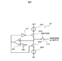
- FIG. 9 is a circuit configuration diagram of the diagnostic current generation circuit 801.
- the diagnostic current generation circuit 801 is activated by being connected to the synchronous rectifier circuit output terminal 105 by the switch C901 when the diagnostic signal is H, that is, in the diagnostic mode.
- the synchronous rectifier circuit output terminal 105 is connected to the current source A 904 and the current source B 905 via the switch A 902 and the switch B 903, respectively.
- the comparator 906 compares the voltage of the synchronous rectifier circuit output terminal 105 with the voltage Vbias, and outputs H when the synchronous rectifier circuit output terminal 105 is higher than Vbias and outputs L when the voltage is lower.
- the output of the comparator 906 is directly input to the switch A 902 via the inverter 907 and to the switch B 903.
- the switch A902 When the output of the comparator 906 is H, that is, when the synchronous rectifier circuit output terminal 105 is higher than Vbias, the switch A902 is turned OFF and the switch B903 is turned ON, and the output of the comparator 906 is L, that is, the synchronous rectifier circuit output terminal 105. Is lower than Vbias, the switch A902 is turned on and the switch B903 is turned off.
- the current source A904 flows the diagnostic current toward the synchronous rectifier circuit output terminal 105 and charges the terminal capacitor 107 while the switch A902 is ON and the switch C901 is ON. Further, the current source B905 draws the diagnostic current from the synchronous rectifier circuit output terminal 105 and draws the charge of the terminal capacitor 107 while the switch B903 is ON and the switch C901 is ON. Thus, the diagnostic current generation circuit 801 charges and discharges the terminal capacitor 107 with the diagnostic current during the diagnostic mode, and controls the voltage of the synchronous rectifier circuit output terminal 105 to Vbias.
- FIG. 10 is a timing chart showing an example of the operation of this embodiment.
- the connection state of the synchronous rectifier circuit output terminal 105 is normal, at times t10 and t11, as described above, when the diagnostic current is set sufficiently small, the voltage of the synchronous rectifier circuit output terminal 105 during the diagnostic mode is As shown in FIG. 10 (f), the voltage becomes higher than Vbias, and the diagnostic current shown in FIG. 10 (e) is drawn from the synchronous rectifier circuit output terminal 105, but the synchronous rectifier circuit output terminal shown in FIG. 10 (f). The voltage 105 rises to near the power supply voltage VB.
- the voltage of the synchronous rectifier circuit output terminal 105 is GND as shown in FIG. 10 (f) at time t12 immediately after shifting to the diagnostic mode.
- the diagnostic current shown in FIG. 10 (e) flows into the synchronous rectifier circuit output terminal 105, and the voltage at the synchronous rectifier circuit output terminal 105 is raised to Vbias as shown in FIG. 10 (f).
- the diagnosis current shown in FIG. 10 (f) When the voltage at the synchronous rectifier circuit output terminal 105 reaches Vbias, the diagnosis current shown in FIG.
- the voltage monitor circuit 111 detects that the voltage at the synchronous rectifier circuit output terminal 105 has remained below the voltage threshold during the filter time during the diagnosis mode, and determines that the state of the synchronous rectifier circuit output terminal 105 is broken. Then, the disconnection diagnosis result B shown in FIG. As a result, as shown in FIG. 10 (l), the OR gate 112 outputs the disconnection diagnosis result C as H in the disconnection state.
- the diagnosis current generator circuit 801 controls the voltage of the synchronous rectifier circuit output terminal 105 during the diagnosis mode, thereby enabling more stable diagnosis. For example, if the voltage of the synchronous rectifier circuit output terminal 105 becomes equal to or higher than the voltage threshold due to disturbance noise despite the disconnection state, the diagnostic current is drawn and the voltage of the synchronous rectifier circuit output terminal 105 is reduced within the filter time. , It can prevent an erroneous normal state determination.
- the case where the synchronous rectifier circuit output terminal 105 is about to be disconnected and the resistance between the synchronous rectifier circuit output terminal 105 and the power supply voltage VB of the load 106 becomes a high resistance is defined as a disconnected state.
- the resistance value between the synchronous rectifier circuit output terminal 105 to be detected as a disconnection state and the power supply of the load 106 is R, and the diagnostic current to be drawn is I
- the voltage at the synchronous rectifier circuit output terminal 105 is VB-I. XR.
- the low side configuration in which the load 106 is connected to the power supply voltage VB has been described as an example, but a high side configuration may be used.
- a high side configuration may be used.
- the high-side configuration it is possible to detect a stable diagnosis and a state of disconnection.
- the value of Vbias at this time needs to be set between the voltage threshold and the power supply voltage VB.
- FIG. 11 is a circuit configuration diagram of the fifth embodiment.
- the present embodiment is different from the first embodiment in the configuration of an engine valve timing control system (hereinafter referred to as VTC: Valve Timing Control System) 1101, a failure determination circuit 1102, and a warning light 1103.
- VTC Valve Timing Control System
- a failure determination circuit 1102 a failure determination circuit 1102
- the load driving device 101 is mounted on an automobile and controls the VTC 1101 by driving a solenoid valve incorporated in the VTC 1101.
- VTC1101 plays the role of continuously changing the valve timing of the engine according to the engine speed, temperature, load, and other operating conditions. As a result, the optimal valve timing can be obtained in the entire operating range. In addition to reducing air pollutants in the exhaust gas emitted, fuel consumption and engine output / performance are improved.
- the failure determination circuit 1102 When the disconnection diagnosis result C is H, the failure determination circuit 1102 turns on the warning lamp 1103 to notify the user of the disconnection of the VTC 1101. At this time, the failure determination circuit 1102 determines that the VTC 1101 is definitely disconnected only when, for example, H in the disconnection diagnosis result C is detected continuously for a certain period, and turns on the warning lamp 1103. For example, a more reliable warning can be implemented.
- the disconnection diagnosis performed by turning off both the high-side FET 102 and the low-side FET 103 during the diagnosis mode is applied to the VTC 1101, so that the entire operation range from the high duty ratio to the low duty ratio is applied.
- the disconnection diagnosis can be carried out reliably while suppressing the influence on the operation of the VTC 1101. It is possible to reduce the increase of air pollutants in the exhaust gas and the deterioration of fuel consumption and engine output / performance.
- the load driving device 101 includes a synchronous rectification circuit 104 having a driving side switching element (high side FET 102 or low side FET 103) and a return side switching element (low side FET 103 or high side FET 102), and a driver for controlling the synchronous rectification circuit 104.
- a control circuit 108, and a voltage monitor circuit 111 that monitors the voltage at the output terminal of the synchronous rectifier circuit 104.
- the return-side switching element is also controlled to be turned off, and the voltage monitor circuit 111 detects that the monitored voltage is within a predetermined voltage range during the period in which both the drive-side switching element and the return-side switching element are turned off.
- Check normal state To. it is possible to detect in a short time whether the output side of the synchronous rectifier circuit is disconnected or in a normal state during driving with a low load current.
- the present invention is not limited to the above-described embodiments, and other forms conceivable within the scope of the technical idea of the present invention are also included in the scope of the present invention as long as the characteristics of the present invention are not impaired. . Moreover, it is good also as a structure which combined the above-mentioned Example.
Landscapes
- Engineering & Computer Science (AREA)
- Power Engineering (AREA)
- Automation & Control Theory (AREA)
- Mechanical Engineering (AREA)
- Transportation (AREA)
- Physics & Mathematics (AREA)
- General Physics & Mathematics (AREA)
- General Health & Medical Sciences (AREA)
- Biomedical Technology (AREA)
- Human Computer Interaction (AREA)
- Health & Medical Sciences (AREA)
- Rectifiers (AREA)
- Dc-Dc Converters (AREA)
- Testing Of Short-Circuits, Discontinuities, Leakage, Or Incorrect Line Connections (AREA)
- Emergency Protection Circuit Devices (AREA)
Abstract
Dans les procédés antérieurs, au moins un cycle de temps de diagnostic était nécessaire afin de détecter des impulsions, et un problème a été présenté selon lequel le temps de diagnostic était long. Le dispositif d'attaque de charge comprend un élément de commutation côté attaque, un circuit redresseur de synchronisation ayant un élément de commutation côté reflux, un circuit de commande d'élément d'attaque pour commander le circuit redresseur de synchronisation, et un circuit de surveillance de tension pour surveiller si la tension d'une borne de sortie du circuit redresseur de synchronisation est à l'intérieur d'une plage de tension prescrite ou non. Lorsqu'une instruction de diagnostic est reçue, le circuit de commande d'élément d'attaque effectue une commande de telle sorte que, lorsque l'élément de commutation côté attaque est commuté d'ACTIVÉ à DÉSACTIVÉ, l'élément de commutation côté reflux est également DÉSACTIVÉ. Dans une période au cours de laquelle l'élément de commutation côté attaque et l'élément de commutation côté reflux sont tous les deux DÉSACTIVÉS, le circuit de surveillance de tension détecte un état normal lorsque la tension qui est surveillée est à un niveau normal.
Priority Applications (4)
| Application Number | Priority Date | Filing Date | Title |
|---|---|---|---|
| US17/054,973 US11635472B2 (en) | 2018-05-16 | 2019-02-14 | Load driving device |
| DE112019001982.1T DE112019001982T5 (de) | 2018-05-16 | 2019-02-14 | Lastansteuervorrichtung |
| JP2020518981A JP6989697B2 (ja) | 2018-05-16 | 2019-02-14 | 負荷駆動装置 |
| CN201980027609.9A CN112074749B (zh) | 2018-05-16 | 2019-02-14 | 负载驱动装置 |
Applications Claiming Priority (2)
| Application Number | Priority Date | Filing Date | Title |
|---|---|---|---|
| JP2018-094299 | 2018-05-16 | ||
| JP2018094299 | 2018-05-16 |
Publications (1)
| Publication Number | Publication Date |
|---|---|
| WO2019220716A1 true WO2019220716A1 (fr) | 2019-11-21 |
Family
ID=68540040
Family Applications (1)
| Application Number | Title | Priority Date | Filing Date |
|---|---|---|---|
| PCT/JP2019/005219 WO2019220716A1 (fr) | 2018-05-16 | 2019-02-14 | Dispositif d'attaque de charge |
Country Status (5)
| Country | Link |
|---|---|
| US (1) | US11635472B2 (fr) |
| JP (1) | JP6989697B2 (fr) |
| CN (1) | CN112074749B (fr) |
| DE (1) | DE112019001982T5 (fr) |
| WO (1) | WO2019220716A1 (fr) |
Cited By (2)
| Publication number | Priority date | Publication date | Assignee | Title |
|---|---|---|---|---|
| WO2022113471A1 (fr) * | 2020-11-26 | 2022-06-02 | 日立Astemo株式会社 | Dispositif de pilotage de charge et procédé de diagnostic de dispositif de pilotage de charge |
| JP2023019873A (ja) * | 2021-07-30 | 2023-02-09 | パナソニックIpマネジメント株式会社 | 負荷短絡検知方法及び負荷短絡検知装置 |
Families Citing this family (1)
| Publication number | Priority date | Publication date | Assignee | Title |
|---|---|---|---|---|
| JP2022056767A (ja) * | 2020-09-30 | 2022-04-11 | 日立Astemo株式会社 | 電磁弁駆動装置 |
Citations (7)
| Publication number | Priority date | Publication date | Assignee | Title |
|---|---|---|---|---|
| JPH0875811A (ja) * | 1994-09-09 | 1996-03-22 | Tokimec Inc | 断線検知回路 |
| JP2011053175A (ja) * | 2009-09-04 | 2011-03-17 | Toyota Motor Corp | 断線検知装置 |
| JP2012143048A (ja) * | 2010-12-28 | 2012-07-26 | Denso Corp | 断線検出回路 |
| JP2012222855A (ja) * | 2011-04-04 | 2012-11-12 | Denso Corp | モータ駆動装置 |
| JP2013236483A (ja) * | 2012-05-09 | 2013-11-21 | Denso Corp | 断線検出回路 |
| US20140340095A1 (en) * | 2012-02-17 | 2014-11-20 | Allison Transmission, Inc. | High voltage cable detection using rotating machine in hybrid vehicles |
| JP2014239571A (ja) * | 2013-06-06 | 2014-12-18 | 株式会社デンソー | 監視回路 |
Family Cites Families (8)
| Publication number | Priority date | Publication date | Assignee | Title |
|---|---|---|---|---|
| JP2656532B2 (ja) * | 1988-03-11 | 1997-09-24 | 株式会社日立製作所 | 電路状態検出装置およびそれを用いた電気装置 |
| JP2002010474A (ja) * | 2000-06-20 | 2002-01-11 | Fujitsu General Ltd | 電源保護装置 |
| JP2007014056A (ja) * | 2005-06-28 | 2007-01-18 | Tamura Seisakusho Co Ltd | 同期整流回路 |
| JP2009168533A (ja) * | 2008-01-11 | 2009-07-30 | Mitsubishi Heavy Ind Ltd | 計測または制御手段における信号状態の診断装置 |
| US8981598B2 (en) * | 2008-07-02 | 2015-03-17 | Powermat Technologies Ltd. | Energy efficient inductive power transmission system and method |
| JP5203859B2 (ja) * | 2008-09-01 | 2013-06-05 | 日立オートモティブシステムズ株式会社 | 電磁負荷回路の故障診断装置 |
| JP6365330B2 (ja) * | 2015-02-03 | 2018-08-01 | 株式会社デンソー | 異常検出回路 |
| JP6878156B2 (ja) * | 2016-07-01 | 2021-05-26 | ローム株式会社 | Dc/dcコンバータ、同期整流コントローラ、電源アダプタおよび電子機器 |
-
2019
- 2019-02-14 US US17/054,973 patent/US11635472B2/en active Active
- 2019-02-14 DE DE112019001982.1T patent/DE112019001982T5/de active Pending
- 2019-02-14 CN CN201980027609.9A patent/CN112074749B/zh active Active
- 2019-02-14 JP JP2020518981A patent/JP6989697B2/ja active Active
- 2019-02-14 WO PCT/JP2019/005219 patent/WO2019220716A1/fr active Application Filing
Patent Citations (7)
| Publication number | Priority date | Publication date | Assignee | Title |
|---|---|---|---|---|
| JPH0875811A (ja) * | 1994-09-09 | 1996-03-22 | Tokimec Inc | 断線検知回路 |
| JP2011053175A (ja) * | 2009-09-04 | 2011-03-17 | Toyota Motor Corp | 断線検知装置 |
| JP2012143048A (ja) * | 2010-12-28 | 2012-07-26 | Denso Corp | 断線検出回路 |
| JP2012222855A (ja) * | 2011-04-04 | 2012-11-12 | Denso Corp | モータ駆動装置 |
| US20140340095A1 (en) * | 2012-02-17 | 2014-11-20 | Allison Transmission, Inc. | High voltage cable detection using rotating machine in hybrid vehicles |
| JP2013236483A (ja) * | 2012-05-09 | 2013-11-21 | Denso Corp | 断線検出回路 |
| JP2014239571A (ja) * | 2013-06-06 | 2014-12-18 | 株式会社デンソー | 監視回路 |
Cited By (3)
| Publication number | Priority date | Publication date | Assignee | Title |
|---|---|---|---|---|
| WO2022113471A1 (fr) * | 2020-11-26 | 2022-06-02 | 日立Astemo株式会社 | Dispositif de pilotage de charge et procédé de diagnostic de dispositif de pilotage de charge |
| JP2023019873A (ja) * | 2021-07-30 | 2023-02-09 | パナソニックIpマネジメント株式会社 | 負荷短絡検知方法及び負荷短絡検知装置 |
| JP7261989B2 (ja) | 2021-07-30 | 2023-04-21 | パナソニックIpマネジメント株式会社 | 負荷短絡検知方法及び負荷短絡検知装置 |
Also Published As
| Publication number | Publication date |
|---|---|
| JP6989697B2 (ja) | 2022-01-05 |
| US11635472B2 (en) | 2023-04-25 |
| CN112074749B (zh) | 2023-06-13 |
| DE112019001982T5 (de) | 2021-04-15 |
| US20210218360A1 (en) | 2021-07-15 |
| CN112074749A (zh) | 2020-12-11 |
| JPWO2019220716A1 (ja) | 2021-03-18 |
Similar Documents
| Publication | Publication Date | Title |
|---|---|---|
| US8625249B2 (en) | Control apparatus for electromagnetic inductive load | |
| WO2019220716A1 (fr) | Dispositif d'attaque de charge | |
| JP5776607B2 (ja) | 誘導性負荷駆動装置 | |
| US8487576B2 (en) | Load drive control device and load drive control method | |
| JP4906433B2 (ja) | 車載制御装置 | |
| JP2008022152A (ja) | 電力供給制御装置 | |
| JP2001298988A (ja) | モータ駆動装置 | |
| US9622304B2 (en) | Load driving circuit | |
| CN110045222B (zh) | 一种风扇驱动级的故障诊断方法 | |
| JP4360310B2 (ja) | 駆動装置 | |
| JP5099041B2 (ja) | 燃料ポンプ制御装置 | |
| JP2008029060A (ja) | 半導体装置 | |
| JP2000184582A (ja) | ソレノイド駆動装置 | |
| JP2008228371A (ja) | 車両用電動モータの駆動制御装置 | |
| JP4474782B2 (ja) | 電気負荷駆動装置 | |
| EP3709334A1 (fr) | Dispositif de commande de bobine de contacteur magnétique électronique | |
| JP5857870B2 (ja) | 断線検出回路 | |
| WO2022219965A1 (fr) | Dispositif d'attaque de charge et procédé de commande d'un dispositif de commande électronique | |
| JP2003219631A (ja) | 電圧駆動型半導体素子の異常検出方法 | |
| US20220239295A1 (en) | Load Drive Device and Control Method of Load Drive Device | |
| JP6084151B2 (ja) | Dc−dcコンバータ | |
| WO2023286667A1 (fr) | Dispositif d'excitation de charge inductive, et dispositif de détection de rupture de fil pour circuit d'excitation de charge inductive | |
| JP2002345291A (ja) | 電磁作動器駆動装置 | |
| WO2022270020A1 (fr) | Dispositif de commande électronique et procédé de commande de dispositif de commande électronique | |
| JP2005039946A (ja) | 自励発振式負荷駆動装置 |
Legal Events
| Date | Code | Title | Description |
|---|---|---|---|
| 121 | Ep: the epo has been informed by wipo that ep was designated in this application |
Ref document number: 19803340 Country of ref document: EP Kind code of ref document: A1 |
|
| ENP | Entry into the national phase |
Ref document number: 2020518981 Country of ref document: JP Kind code of ref document: A |
|
| 122 | Ep: pct application non-entry in european phase |
Ref document number: 19803340 Country of ref document: EP Kind code of ref document: A1 |