WO2019208792A1 - 電池 - Google Patents
電池 Download PDFInfo
- Publication number
- WO2019208792A1 WO2019208792A1 PCT/JP2019/018001 JP2019018001W WO2019208792A1 WO 2019208792 A1 WO2019208792 A1 WO 2019208792A1 JP 2019018001 W JP2019018001 W JP 2019018001W WO 2019208792 A1 WO2019208792 A1 WO 2019208792A1
- Authority
- WO
- WIPO (PCT)
- Prior art keywords
- positive electrode
- current collector
- negative electrode
- electrode current
- active material
- Prior art date
Links
- 239000007774 positive electrode material Substances 0.000 claims abstract description 91
- 239000011230 binding agent Substances 0.000 claims abstract description 84
- 238000002844 melting Methods 0.000 claims abstract description 49
- 230000008018 melting Effects 0.000 claims abstract description 49
- 239000006258 conductive agent Substances 0.000 claims abstract description 40
- YCKRFDGAMUMZLT-UHFFFAOYSA-N Fluorine atom Chemical compound [F] YCKRFDGAMUMZLT-UHFFFAOYSA-N 0.000 claims abstract description 36
- 239000011737 fluorine Substances 0.000 claims abstract description 36
- 229910052731 fluorine Inorganic materials 0.000 claims abstract description 36
- 239000007773 negative electrode material Substances 0.000 claims abstract description 34
- 239000002245 particle Substances 0.000 claims abstract description 22
- 239000002033 PVDF binder Substances 0.000 claims description 71
- 229920002981 polyvinylidene fluoride Polymers 0.000 claims description 71
- 239000000463 material Substances 0.000 claims description 63
- 230000002093 peripheral effect Effects 0.000 claims description 59
- 239000008151 electrolyte solution Substances 0.000 claims description 22
- 239000010954 inorganic particle Substances 0.000 claims description 16
- 239000011245 gel electrolyte Substances 0.000 claims description 9
- CPLXHLVBOLITMK-UHFFFAOYSA-N magnesium oxide Inorganic materials [Mg]=O CPLXHLVBOLITMK-UHFFFAOYSA-N 0.000 claims description 8
- GWEVSGVZZGPLCZ-UHFFFAOYSA-N Titan oxide Chemical compound O=[Ti]=O GWEVSGVZZGPLCZ-UHFFFAOYSA-N 0.000 claims description 7
- 229910044991 metal oxide Inorganic materials 0.000 claims description 7
- 150000004706 metal oxides Chemical class 0.000 claims description 7
- VYPSYNLAJGMNEJ-UHFFFAOYSA-N Silicium dioxide Chemical compound O=[Si]=O VYPSYNLAJGMNEJ-UHFFFAOYSA-N 0.000 claims description 6
- 239000000395 magnesium oxide Substances 0.000 claims description 5
- 229910001593 boehmite Inorganic materials 0.000 claims description 2
- FAHBNUUHRFUEAI-UHFFFAOYSA-M hydroxidooxidoaluminium Chemical compound O[Al]=O FAHBNUUHRFUEAI-UHFFFAOYSA-M 0.000 claims description 2
- AXZKOIWUVFPNLO-UHFFFAOYSA-N magnesium;oxygen(2-) Chemical compound [O-2].[Mg+2] AXZKOIWUVFPNLO-UHFFFAOYSA-N 0.000 claims description 2
- TWNQGVIAIRXVLR-UHFFFAOYSA-N oxo(oxoalumanyloxy)alumane Chemical compound O=[Al]O[Al]=O TWNQGVIAIRXVLR-UHFFFAOYSA-N 0.000 claims description 2
- SIWVEOZUMHYXCS-UHFFFAOYSA-N oxo(oxoyttriooxy)yttrium Chemical compound O=[Y]O[Y]=O SIWVEOZUMHYXCS-UHFFFAOYSA-N 0.000 claims description 2
- RVTZCBVAJQQJTK-UHFFFAOYSA-N oxygen(2-);zirconium(4+) Chemical compound [O-2].[O-2].[Zr+4] RVTZCBVAJQQJTK-UHFFFAOYSA-N 0.000 claims description 2
- 229910052814 silicon oxide Inorganic materials 0.000 claims description 2
- OGIDPMRJRNCKJF-UHFFFAOYSA-N titanium oxide Inorganic materials [Ti]=O OGIDPMRJRNCKJF-UHFFFAOYSA-N 0.000 claims description 2
- 229910001928 zirconium oxide Inorganic materials 0.000 claims description 2
- XLOMVQKBTHCTTD-UHFFFAOYSA-N Zinc monoxide Chemical compound [Zn]=O XLOMVQKBTHCTTD-UHFFFAOYSA-N 0.000 claims 2
- 239000011787 zinc oxide Substances 0.000 claims 1
- 239000010410 layer Substances 0.000 description 135
- 230000000052 comparative effect Effects 0.000 description 68
- 208000027418 Wounds and injury Diseases 0.000 description 58
- 239000000203 mixture Substances 0.000 description 49
- -1 polypropylene Polymers 0.000 description 47
- 229920005989 resin Polymers 0.000 description 35
- 239000011347 resin Substances 0.000 description 35
- 239000003792 electrolyte Substances 0.000 description 32
- 239000011888 foil Substances 0.000 description 32
- 229910052744 lithium Inorganic materials 0.000 description 32
- WHXSMMKQMYFTQS-UHFFFAOYSA-N Lithium Chemical compound [Li] WHXSMMKQMYFTQS-UHFFFAOYSA-N 0.000 description 30
- 229920001577 copolymer Polymers 0.000 description 26
- PXHVJJICTQNCMI-UHFFFAOYSA-N Nickel Chemical compound [Ni] PXHVJJICTQNCMI-UHFFFAOYSA-N 0.000 description 25
- 238000004804 winding Methods 0.000 description 24
- 239000002131 composite material Substances 0.000 description 23
- 229910052751 metal Inorganic materials 0.000 description 22
- 150000001875 compounds Chemical class 0.000 description 21
- 239000004698 Polyethylene Substances 0.000 description 20
- 239000002184 metal Substances 0.000 description 20
- 229920000573 polyethylene Polymers 0.000 description 20
- 229910052782 aluminium Inorganic materials 0.000 description 18
- XAGFODPZIPBFFR-UHFFFAOYSA-N aluminium Chemical compound [Al] XAGFODPZIPBFFR-UHFFFAOYSA-N 0.000 description 18
- 238000002156 mixing Methods 0.000 description 18
- XEEYBQQBJWHFJM-UHFFFAOYSA-N Iron Chemical compound [Fe] XEEYBQQBJWHFJM-UHFFFAOYSA-N 0.000 description 17
- 238000000034 method Methods 0.000 description 17
- 239000002002 slurry Substances 0.000 description 17
- 229910012851 LiCoO 2 Inorganic materials 0.000 description 16
- 239000006229 carbon black Substances 0.000 description 16
- CKFRRHLHAJZIIN-UHFFFAOYSA-N cobalt lithium Chemical compound [Li].[Co] CKFRRHLHAJZIIN-UHFFFAOYSA-N 0.000 description 16
- 239000002904 solvent Substances 0.000 description 16
- 230000000694 effects Effects 0.000 description 14
- 230000004048 modification Effects 0.000 description 14
- 238000012986 modification Methods 0.000 description 14
- 238000009782 nail-penetration test Methods 0.000 description 14
- SECXISVLQFMRJM-UHFFFAOYSA-N N-Methylpyrrolidone Chemical compound CN1CCCC1=O SECXISVLQFMRJM-UHFFFAOYSA-N 0.000 description 13
- 239000002344 surface layer Substances 0.000 description 13
- 239000004743 Polypropylene Substances 0.000 description 12
- 229920001155 polypropylene Polymers 0.000 description 12
- 230000001681 protective effect Effects 0.000 description 12
- 239000011135 tin Substances 0.000 description 12
- RYGMFSIKBFXOCR-UHFFFAOYSA-N Copper Chemical compound [Cu] RYGMFSIKBFXOCR-UHFFFAOYSA-N 0.000 description 11
- ATJFFYVFTNAWJD-UHFFFAOYSA-N Tin Chemical compound [Sn] ATJFFYVFTNAWJD-UHFFFAOYSA-N 0.000 description 11
- 238000011156 evaluation Methods 0.000 description 11
- 230000008961 swelling Effects 0.000 description 11
- 229910052718 tin Inorganic materials 0.000 description 11
- 239000010936 titanium Substances 0.000 description 11
- BQCIDUSAKPWEOX-UHFFFAOYSA-N 1,1-Difluoroethene Chemical compound FC(F)=C BQCIDUSAKPWEOX-UHFFFAOYSA-N 0.000 description 10
- RTAQQCXQSZGOHL-UHFFFAOYSA-N Titanium Chemical compound [Ti] RTAQQCXQSZGOHL-UHFFFAOYSA-N 0.000 description 10
- 239000010949 copper Substances 0.000 description 10
- OKTJSMMVPCPJKN-UHFFFAOYSA-N Carbon Chemical compound [C] OKTJSMMVPCPJKN-UHFFFAOYSA-N 0.000 description 9
- 229910052802 copper Inorganic materials 0.000 description 9
- 229910052759 nickel Inorganic materials 0.000 description 9
- 229920001343 polytetrafluoroethylene Polymers 0.000 description 9
- 239000004810 polytetrafluoroethylene Substances 0.000 description 9
- 238000002360 preparation method Methods 0.000 description 9
- 238000003860 storage Methods 0.000 description 9
- 229910052719 titanium Inorganic materials 0.000 description 9
- KMTRUDSVKNLOMY-UHFFFAOYSA-N Ethylene carbonate Chemical compound O=C1OCCO1 KMTRUDSVKNLOMY-UHFFFAOYSA-N 0.000 description 8
- 238000010438 heat treatment Methods 0.000 description 8
- 229910052742 iron Inorganic materials 0.000 description 8
- 238000004519 manufacturing process Methods 0.000 description 8
- 229920000642 polymer Polymers 0.000 description 8
- RUOJZAUFBMNUDX-UHFFFAOYSA-N propylene carbonate Chemical compound CC1COC(=O)O1 RUOJZAUFBMNUDX-UHFFFAOYSA-N 0.000 description 8
- 238000007789 sealing Methods 0.000 description 8
- XUIMIQQOPSSXEZ-UHFFFAOYSA-N Silicon Chemical compound [Si] XUIMIQQOPSSXEZ-UHFFFAOYSA-N 0.000 description 7
- HCHKCACWOHOZIP-UHFFFAOYSA-N Zinc Chemical compound [Zn] HCHKCACWOHOZIP-UHFFFAOYSA-N 0.000 description 7
- 239000011651 chromium Substances 0.000 description 7
- 229910017052 cobalt Inorganic materials 0.000 description 7
- 239000010941 cobalt Substances 0.000 description 7
- GUTLYIVDDKVIGB-UHFFFAOYSA-N cobalt atom Chemical compound [Co] GUTLYIVDDKVIGB-UHFFFAOYSA-N 0.000 description 7
- 239000000470 constituent Substances 0.000 description 7
- 238000007599 discharging Methods 0.000 description 7
- 239000011883 electrode binding agent Substances 0.000 description 7
- 239000011777 magnesium Substances 0.000 description 7
- 239000011572 manganese Substances 0.000 description 7
- 229910052710 silicon Inorganic materials 0.000 description 7
- 239000010703 silicon Substances 0.000 description 7
- 239000011701 zinc Substances 0.000 description 7
- 229910052725 zinc Inorganic materials 0.000 description 7
- ZOXJGFHDIHLPTG-UHFFFAOYSA-N Boron Chemical compound [B] ZOXJGFHDIHLPTG-UHFFFAOYSA-N 0.000 description 6
- VYZAMTAEIAYCRO-UHFFFAOYSA-N Chromium Chemical compound [Cr] VYZAMTAEIAYCRO-UHFFFAOYSA-N 0.000 description 6
- FYYHWMGAXLPEAU-UHFFFAOYSA-N Magnesium Chemical compound [Mg] FYYHWMGAXLPEAU-UHFFFAOYSA-N 0.000 description 6
- 229910052796 boron Inorganic materials 0.000 description 6
- 239000011575 calcium Substances 0.000 description 6
- 239000003575 carbonaceous material Substances 0.000 description 6
- 229910052804 chromium Inorganic materials 0.000 description 6
- 239000005001 laminate film Substances 0.000 description 6
- 229910052749 magnesium Inorganic materials 0.000 description 6
- 230000007246 mechanism Effects 0.000 description 6
- 229920002239 polyacrylonitrile Polymers 0.000 description 6
- 230000008569 process Effects 0.000 description 6
- 235000002639 sodium chloride Nutrition 0.000 description 6
- OYPRJOBELJOOCE-UHFFFAOYSA-N Calcium Chemical compound [Ca] OYPRJOBELJOOCE-UHFFFAOYSA-N 0.000 description 5
- ZOKXTWBITQBERF-UHFFFAOYSA-N Molybdenum Chemical compound [Mo] ZOKXTWBITQBERF-UHFFFAOYSA-N 0.000 description 5
- 229910045601 alloy Inorganic materials 0.000 description 5
- 239000000956 alloy Substances 0.000 description 5
- PNEYBMLMFCGWSK-UHFFFAOYSA-N aluminium oxide Inorganic materials [O-2].[O-2].[O-2].[Al+3].[Al+3] PNEYBMLMFCGWSK-UHFFFAOYSA-N 0.000 description 5
- 229910052791 calcium Inorganic materials 0.000 description 5
- 238000006243 chemical reaction Methods 0.000 description 5
- 239000011248 coating agent Substances 0.000 description 5
- 238000000576 coating method Methods 0.000 description 5
- IEJIGPNLZYLLBP-UHFFFAOYSA-N dimethyl carbonate Chemical compound COC(=O)OC IEJIGPNLZYLLBP-UHFFFAOYSA-N 0.000 description 5
- 239000000835 fiber Substances 0.000 description 5
- WPBNNNQJVZRUHP-UHFFFAOYSA-L manganese(2+);methyl n-[[2-(methoxycarbonylcarbamothioylamino)phenyl]carbamothioyl]carbamate;n-[2-(sulfidocarbothioylamino)ethyl]carbamodithioate Chemical compound [Mn+2].[S-]C(=S)NCCNC([S-])=S.COC(=O)NC(=S)NC1=CC=CC=C1NC(=S)NC(=O)OC WPBNNNQJVZRUHP-UHFFFAOYSA-L 0.000 description 5
- 229910052750 molybdenum Inorganic materials 0.000 description 5
- 239000011733 molybdenum Substances 0.000 description 5
- 239000011255 nonaqueous electrolyte Substances 0.000 description 5
- 229910052760 oxygen Inorganic materials 0.000 description 5
- 239000005022 packaging material Substances 0.000 description 5
- 229910052712 strontium Inorganic materials 0.000 description 5
- CIOAGBVUUVVLOB-UHFFFAOYSA-N strontium atom Chemical compound [Sr] CIOAGBVUUVVLOB-UHFFFAOYSA-N 0.000 description 5
- 239000000126 substance Substances 0.000 description 5
- 238000012360 testing method Methods 0.000 description 5
- WFKWXMTUELFFGS-UHFFFAOYSA-N tungsten Chemical compound [W] WFKWXMTUELFFGS-UHFFFAOYSA-N 0.000 description 5
- 229910052721 tungsten Inorganic materials 0.000 description 5
- 239000010937 tungsten Substances 0.000 description 5
- 229910052720 vanadium Inorganic materials 0.000 description 5
- 229920002134 Carboxymethyl cellulose Polymers 0.000 description 4
- OIFBSDVPJOWBCH-UHFFFAOYSA-N Diethyl carbonate Chemical compound CCOC(=O)OCC OIFBSDVPJOWBCH-UHFFFAOYSA-N 0.000 description 4
- 229910013870 LiPF 6 Inorganic materials 0.000 description 4
- HBBGRARXTFLTSG-UHFFFAOYSA-N Lithium ion Chemical compound [Li+] HBBGRARXTFLTSG-UHFFFAOYSA-N 0.000 description 4
- PPBRXRYQALVLMV-UHFFFAOYSA-N Styrene Chemical compound C=CC1=CC=CC=C1 PPBRXRYQALVLMV-UHFFFAOYSA-N 0.000 description 4
- 239000004760 aramid Substances 0.000 description 4
- 239000012298 atmosphere Substances 0.000 description 4
- 238000005336 cracking Methods 0.000 description 4
- 230000007423 decrease Effects 0.000 description 4
- 230000020169 heat generation Effects 0.000 description 4
- HCDGVLDPFQMKDK-UHFFFAOYSA-N hexafluoropropylene Chemical group FC(F)=C(F)C(F)(F)F HCDGVLDPFQMKDK-UHFFFAOYSA-N 0.000 description 4
- 229910001416 lithium ion Inorganic materials 0.000 description 4
- 239000012046 mixed solvent Substances 0.000 description 4
- 229920005672 polyolefin resin Polymers 0.000 description 4
- 239000011241 protective layer Substances 0.000 description 4
- 150000003839 salts Chemical class 0.000 description 4
- 229920003048 styrene butadiene rubber Polymers 0.000 description 4
- GPPXJZIENCGNKB-UHFFFAOYSA-N vanadium Chemical compound [V]#[V] GPPXJZIENCGNKB-UHFFFAOYSA-N 0.000 description 4
- WEVYAHXRMPXWCK-UHFFFAOYSA-N Acetonitrile Chemical compound CC#N WEVYAHXRMPXWCK-UHFFFAOYSA-N 0.000 description 3
- ZMXDDKWLCZADIW-UHFFFAOYSA-N N,N-Dimethylformamide Chemical compound CN(C)C=O ZMXDDKWLCZADIW-UHFFFAOYSA-N 0.000 description 3
- KDLHZDBZIXYQEI-UHFFFAOYSA-N Palladium Chemical compound [Pd] KDLHZDBZIXYQEI-UHFFFAOYSA-N 0.000 description 3
- 239000004372 Polyvinyl alcohol Substances 0.000 description 3
- BQCADISMDOOEFD-UHFFFAOYSA-N Silver Chemical compound [Ag] BQCADISMDOOEFD-UHFFFAOYSA-N 0.000 description 3
- 229920003235 aromatic polyamide Polymers 0.000 description 3
- QVGXLLKOCUKJST-UHFFFAOYSA-N atomic oxygen Chemical compound [O] QVGXLLKOCUKJST-UHFFFAOYSA-N 0.000 description 3
- 229910052797 bismuth Inorganic materials 0.000 description 3
- JCXGWMGPZLAOME-UHFFFAOYSA-N bismuth atom Chemical compound [Bi] JCXGWMGPZLAOME-UHFFFAOYSA-N 0.000 description 3
- 239000006182 cathode active material Substances 0.000 description 3
- 229920001971 elastomer Polymers 0.000 description 3
- 239000007789 gas Substances 0.000 description 3
- 229910052732 germanium Inorganic materials 0.000 description 3
- GNPVGFCGXDBREM-UHFFFAOYSA-N germanium atom Chemical compound [Ge] GNPVGFCGXDBREM-UHFFFAOYSA-N 0.000 description 3
- 229910002804 graphite Inorganic materials 0.000 description 3
- 239000010439 graphite Substances 0.000 description 3
- 150000004678 hydrides Chemical class 0.000 description 3
- 230000006872 improvement Effects 0.000 description 3
- 229910052738 indium Inorganic materials 0.000 description 3
- APFVFJFRJDLVQX-UHFFFAOYSA-N indium atom Chemical compound [In] APFVFJFRJDLVQX-UHFFFAOYSA-N 0.000 description 3
- 208000014674 injury Diseases 0.000 description 3
- 239000011159 matrix material Substances 0.000 description 3
- 229910052752 metalloid Inorganic materials 0.000 description 3
- 239000000178 monomer Substances 0.000 description 3
- 229910021470 non-graphitizable carbon Inorganic materials 0.000 description 3
- 239000004745 nonwoven fabric Substances 0.000 description 3
- 229920001778 nylon Polymers 0.000 description 3
- 230000003647 oxidation Effects 0.000 description 3
- 238000007254 oxidation reaction Methods 0.000 description 3
- 239000001301 oxygen Substances 0.000 description 3
- BASFCYQUMIYNBI-UHFFFAOYSA-N platinum Chemical compound [Pt] BASFCYQUMIYNBI-UHFFFAOYSA-N 0.000 description 3
- 229920002451 polyvinyl alcohol Polymers 0.000 description 3
- 239000005060 rubber Substances 0.000 description 3
- 229910052709 silver Inorganic materials 0.000 description 3
- 239000004332 silver Substances 0.000 description 3
- 239000010935 stainless steel Substances 0.000 description 3
- 229910001220 stainless steel Inorganic materials 0.000 description 3
- 230000008733 trauma Effects 0.000 description 3
- 239000013585 weight reducing agent Substances 0.000 description 3
- VAYTZRYEBVHVLE-UHFFFAOYSA-N 1,3-dioxol-2-one Chemical compound O=C1OC=CO1 VAYTZRYEBVHVLE-UHFFFAOYSA-N 0.000 description 2
- CRMJLJFDPNJIQA-UHFFFAOYSA-N 2,4-difluoro-1-methoxybenzene Chemical compound COC1=CC=C(F)C=C1F CRMJLJFDPNJIQA-UHFFFAOYSA-N 0.000 description 2
- YEJRWHAVMIAJKC-UHFFFAOYSA-N 4-Butyrolactone Chemical compound O=C1CCCO1 YEJRWHAVMIAJKC-UHFFFAOYSA-N 0.000 description 2
- 239000004925 Acrylic resin Substances 0.000 description 2
- 229920000178 Acrylic resin Polymers 0.000 description 2
- 229910018072 Al 2 O 3 Inorganic materials 0.000 description 2
- 229920000049 Carbon (fiber) Polymers 0.000 description 2
- XTHFKEDIFFGKHM-UHFFFAOYSA-N Dimethoxyethane Chemical compound COCCOC XTHFKEDIFFGKHM-UHFFFAOYSA-N 0.000 description 2
- IAZDPXIOMUYVGZ-UHFFFAOYSA-N Dimethylsulphoxide Chemical compound CS(C)=O IAZDPXIOMUYVGZ-UHFFFAOYSA-N 0.000 description 2
- UQSXHKLRYXJYBZ-UHFFFAOYSA-N Iron oxide Chemical compound [Fe]=O UQSXHKLRYXJYBZ-UHFFFAOYSA-N 0.000 description 2
- PWHULOQIROXLJO-UHFFFAOYSA-N Manganese Chemical compound [Mn] PWHULOQIROXLJO-UHFFFAOYSA-N 0.000 description 2
- 239000004677 Nylon Substances 0.000 description 2
- 229910019142 PO4 Inorganic materials 0.000 description 2
- 229920003171 Poly (ethylene oxide) Polymers 0.000 description 2
- 239000004962 Polyamide-imide Substances 0.000 description 2
- OFOBLEOULBTSOW-UHFFFAOYSA-N Propanedioic acid Natural products OC(=O)CC(O)=O OFOBLEOULBTSOW-UHFFFAOYSA-N 0.000 description 2
- FAPWRFPIFSIZLT-UHFFFAOYSA-M Sodium chloride Chemical compound [Na+].[Cl-] FAPWRFPIFSIZLT-UHFFFAOYSA-M 0.000 description 2
- WYURNTSHIVDZCO-UHFFFAOYSA-N Tetrahydrofuran Chemical compound C1CCOC1 WYURNTSHIVDZCO-UHFFFAOYSA-N 0.000 description 2
- QCWXUUIWCKQGHC-UHFFFAOYSA-N Zirconium Chemical compound [Zr] QCWXUUIWCKQGHC-UHFFFAOYSA-N 0.000 description 2
- MCMNRKCIXSYSNV-UHFFFAOYSA-N Zirconium dioxide Chemical compound O=[Zr]=O MCMNRKCIXSYSNV-UHFFFAOYSA-N 0.000 description 2
- 239000011149 active material Substances 0.000 description 2
- 239000000654 additive Substances 0.000 description 2
- 239000002313 adhesive film Substances 0.000 description 2
- 239000012790 adhesive layer Substances 0.000 description 2
- 229910052787 antimony Inorganic materials 0.000 description 2
- WATWJIUSRGPENY-UHFFFAOYSA-N antimony atom Chemical compound [Sb] WATWJIUSRGPENY-UHFFFAOYSA-N 0.000 description 2
- 239000004917 carbon fiber Substances 0.000 description 2
- 239000002041 carbon nanotube Substances 0.000 description 2
- 229910021393 carbon nanotube Inorganic materials 0.000 description 2
- 239000001768 carboxy methyl cellulose Substances 0.000 description 2
- 235000010948 carboxy methyl cellulose Nutrition 0.000 description 2
- 150000001732 carboxylic acid derivatives Chemical class 0.000 description 2
- 239000008112 carboxymethyl-cellulose Substances 0.000 description 2
- 230000008859 change Effects 0.000 description 2
- UUAGAQFQZIEFAH-UHFFFAOYSA-N chlorotrifluoroethylene Chemical group FC(F)=C(F)Cl UUAGAQFQZIEFAH-UHFFFAOYSA-N 0.000 description 2
- 239000000571 coke Substances 0.000 description 2
- 238000004040 coloring Methods 0.000 description 2
- 230000006835 compression Effects 0.000 description 2
- 238000007906 compression Methods 0.000 description 2
- 238000000748 compression moulding Methods 0.000 description 2
- 239000011889 copper foil Substances 0.000 description 2
- 150000005676 cyclic carbonates Chemical class 0.000 description 2
- 239000002612 dispersion medium Substances 0.000 description 2
- 239000011808 electrode reactant Substances 0.000 description 2
- 229920000840 ethylene tetrafluoroethylene copolymer Polymers 0.000 description 2
- 230000004927 fusion Effects 0.000 description 2
- GAEKPEKOJKCEMS-UHFFFAOYSA-N gamma-valerolactone Chemical compound CC1CCC(=O)O1 GAEKPEKOJKCEMS-UHFFFAOYSA-N 0.000 description 2
- 230000009477 glass transition Effects 0.000 description 2
- 229910021469 graphitizable carbon Inorganic materials 0.000 description 2
- 229920001519 homopolymer Polymers 0.000 description 2
- 150000002500 ions Chemical class 0.000 description 2
- AMXOYNBUYSYVKV-UHFFFAOYSA-M lithium bromide Chemical compound [Li+].[Br-] AMXOYNBUYSYVKV-UHFFFAOYSA-M 0.000 description 2
- KWGKDLIKAYFUFQ-UHFFFAOYSA-M lithium chloride Chemical compound [Li+].[Cl-] KWGKDLIKAYFUFQ-UHFFFAOYSA-M 0.000 description 2
- 229910003002 lithium salt Inorganic materials 0.000 description 2
- 159000000002 lithium salts Chemical class 0.000 description 2
- VZCYOOQTPOCHFL-UPHRSURJSA-N maleic acid Chemical compound OC(=O)\C=C/C(O)=O VZCYOOQTPOCHFL-UPHRSURJSA-N 0.000 description 2
- 239000011976 maleic acid Substances 0.000 description 2
- 229910052748 manganese Inorganic materials 0.000 description 2
- 238000005259 measurement Methods 0.000 description 2
- 239000007769 metal material Substances 0.000 description 2
- 229910052976 metal sulfide Inorganic materials 0.000 description 2
- 239000010955 niobium Substances 0.000 description 2
- 150000004767 nitrides Chemical class 0.000 description 2
- 229920006284 nylon film Polymers 0.000 description 2
- 239000010450 olivine Substances 0.000 description 2
- 229910052609 olivine Inorganic materials 0.000 description 2
- 229920000620 organic polymer Polymers 0.000 description 2
- 239000003960 organic solvent Substances 0.000 description 2
- 230000035515 penetration Effects 0.000 description 2
- 235000021317 phosphate Nutrition 0.000 description 2
- 229920002312 polyamide-imide Polymers 0.000 description 2
- 229920000139 polyethylene terephthalate Polymers 0.000 description 2
- 239000005020 polyethylene terephthalate Substances 0.000 description 2
- 229920006254 polymer film Polymers 0.000 description 2
- 239000002861 polymer material Substances 0.000 description 2
- 239000002952 polymeric resin Substances 0.000 description 2
- 229920000098 polyolefin Polymers 0.000 description 2
- 239000011118 polyvinyl acetate Substances 0.000 description 2
- 229920002689 polyvinyl acetate Polymers 0.000 description 2
- 239000002243 precursor Substances 0.000 description 2
- 238000003825 pressing Methods 0.000 description 2
- 239000000377 silicon dioxide Substances 0.000 description 2
- 239000011780 sodium chloride Substances 0.000 description 2
- 239000000243 solution Substances 0.000 description 2
- 239000000758 substrate Substances 0.000 description 2
- 230000001629 suppression Effects 0.000 description 2
- 229920003002 synthetic resin Polymers 0.000 description 2
- BFKJFAAPBSQJPD-UHFFFAOYSA-N tetrafluoroethene Chemical group FC(F)=C(F)F BFKJFAAPBSQJPD-UHFFFAOYSA-N 0.000 description 2
- VZCYOOQTPOCHFL-UHFFFAOYSA-N trans-butenedioic acid Natural products OC(=O)C=CC(O)=O VZCYOOQTPOCHFL-UHFFFAOYSA-N 0.000 description 2
- 229910052723 transition metal Inorganic materials 0.000 description 2
- XLYOFNOQVPJJNP-UHFFFAOYSA-N water Substances O XLYOFNOQVPJJNP-UHFFFAOYSA-N 0.000 description 2
- 230000004580 weight loss Effects 0.000 description 2
- 238000003466 welding Methods 0.000 description 2
- 229910052726 zirconium Inorganic materials 0.000 description 2
- LNAZSHAWQACDHT-XIYTZBAFSA-N (2r,3r,4s,5r,6s)-4,5-dimethoxy-2-(methoxymethyl)-3-[(2s,3r,4s,5r,6r)-3,4,5-trimethoxy-6-(methoxymethyl)oxan-2-yl]oxy-6-[(2r,3r,4s,5r,6r)-4,5,6-trimethoxy-2-(methoxymethyl)oxan-3-yl]oxyoxane Chemical compound CO[C@@H]1[C@@H](OC)[C@H](OC)[C@@H](COC)O[C@H]1O[C@H]1[C@H](OC)[C@@H](OC)[C@H](O[C@H]2[C@@H]([C@@H](OC)[C@H](OC)O[C@@H]2COC)OC)O[C@@H]1COC LNAZSHAWQACDHT-XIYTZBAFSA-N 0.000 description 1
- ZZXUZKXVROWEIF-UHFFFAOYSA-N 1,2-butylene carbonate Chemical compound CCC1COC(=O)O1 ZZXUZKXVROWEIF-UHFFFAOYSA-N 0.000 description 1
- WNXJIVFYUVYPPR-UHFFFAOYSA-N 1,3-dioxolane Chemical compound C1COCO1 WNXJIVFYUVYPPR-UHFFFAOYSA-N 0.000 description 1
- QKPVEISEHYYHRH-UHFFFAOYSA-N 2-methoxyacetonitrile Chemical compound COCC#N QKPVEISEHYYHRH-UHFFFAOYSA-N 0.000 description 1
- JWUJQDFVADABEY-UHFFFAOYSA-N 2-methyltetrahydrofuran Chemical compound CC1CCCO1 JWUJQDFVADABEY-UHFFFAOYSA-N 0.000 description 1
- VWIIJDNADIEEDB-UHFFFAOYSA-N 3-methyl-1,3-oxazolidin-2-one Chemical compound CN1CCOC1=O VWIIJDNADIEEDB-UHFFFAOYSA-N 0.000 description 1
- SBUOHGKIOVRDKY-UHFFFAOYSA-N 4-methyl-1,3-dioxolane Chemical compound CC1COCO1 SBUOHGKIOVRDKY-UHFFFAOYSA-N 0.000 description 1
- FEIQOMCWGDNMHM-UHFFFAOYSA-N 5-phenylpenta-2,4-dienoic acid Chemical compound OC(=O)C=CC=CC1=CC=CC=C1 FEIQOMCWGDNMHM-UHFFFAOYSA-N 0.000 description 1
- PIGFYZPCRLYGLF-UHFFFAOYSA-N Aluminum nitride Chemical compound [Al]#N PIGFYZPCRLYGLF-UHFFFAOYSA-N 0.000 description 1
- PZNSFCLAULLKQX-UHFFFAOYSA-N Boron nitride Chemical compound N#B PZNSFCLAULLKQX-UHFFFAOYSA-N 0.000 description 1
- 229910018871 CoO 2 Inorganic materials 0.000 description 1
- VGGSQFUCUMXWEO-UHFFFAOYSA-N Ethene Chemical compound C=C VGGSQFUCUMXWEO-UHFFFAOYSA-N 0.000 description 1
- 239000001856 Ethyl cellulose Substances 0.000 description 1
- ZZSNKZQZMQGXPY-UHFFFAOYSA-N Ethyl cellulose Chemical compound CCOCC1OC(OC)C(OCC)C(OCC)C1OC1C(O)C(O)C(OC)C(CO)O1 ZZSNKZQZMQGXPY-UHFFFAOYSA-N 0.000 description 1
- 239000005977 Ethylene Substances 0.000 description 1
- 229920000181 Ethylene propylene rubber Polymers 0.000 description 1
- GYHNNYVSQQEPJS-UHFFFAOYSA-N Gallium Chemical compound [Ga] GYHNNYVSQQEPJS-UHFFFAOYSA-N 0.000 description 1
- UFHFLCQGNIYNRP-UHFFFAOYSA-N Hydrogen Chemical compound [H][H] UFHFLCQGNIYNRP-UHFFFAOYSA-N 0.000 description 1
- 229920000663 Hydroxyethyl cellulose Polymers 0.000 description 1
- 239000004354 Hydroxyethyl cellulose Substances 0.000 description 1
- 229910010238 LiAlCl 4 Inorganic materials 0.000 description 1
- 229910015015 LiAsF 6 Inorganic materials 0.000 description 1
- 229910015044 LiB Inorganic materials 0.000 description 1
- 229910013063 LiBF 4 Inorganic materials 0.000 description 1
- 229910013684 LiClO 4 Inorganic materials 0.000 description 1
- 229910013528 LiN(SO2 CF3)2 Inorganic materials 0.000 description 1
- 229910012416 LiNi0.50Co0.20Mn0.30O2 Inorganic materials 0.000 description 1
- CERQOIWHTDAKMF-UHFFFAOYSA-N Methacrylic acid Chemical compound CC(=C)C(O)=O CERQOIWHTDAKMF-UHFFFAOYSA-N 0.000 description 1
- RJUFJBKOKNCXHH-UHFFFAOYSA-N Methyl propionate Chemical compound CCC(=O)OC RJUFJBKOKNCXHH-UHFFFAOYSA-N 0.000 description 1
- 229920000459 Nitrile rubber Polymers 0.000 description 1
- MXRIRQGCELJRSN-UHFFFAOYSA-N O.O.O.[Al] Chemical compound O.O.O.[Al] MXRIRQGCELJRSN-UHFFFAOYSA-N 0.000 description 1
- 229920002845 Poly(methacrylic acid) Polymers 0.000 description 1
- 239000004952 Polyamide Substances 0.000 description 1
- 239000004695 Polyether sulfone Substances 0.000 description 1
- 239000004697 Polyetherimide Substances 0.000 description 1
- 239000004642 Polyimide Substances 0.000 description 1
- 239000004721 Polyphenylene oxide Substances 0.000 description 1
- 239000004734 Polyphenylene sulfide Substances 0.000 description 1
- 239000004793 Polystyrene Substances 0.000 description 1
- XBDQKXXYIPTUBI-UHFFFAOYSA-M Propionate Chemical compound CCC([O-])=O XBDQKXXYIPTUBI-UHFFFAOYSA-M 0.000 description 1
- 229910000676 Si alloy Inorganic materials 0.000 description 1
- 229910052581 Si3N4 Inorganic materials 0.000 description 1
- 229910004298 SiO 2 Inorganic materials 0.000 description 1
- 229910001128 Sn alloy Inorganic materials 0.000 description 1
- 229920002125 Sokalan® Polymers 0.000 description 1
- 229910010413 TiO 2 Inorganic materials 0.000 description 1
- NRTOMJZYCJJWKI-UHFFFAOYSA-N Titanium nitride Chemical compound [Ti]#N NRTOMJZYCJJWKI-UHFFFAOYSA-N 0.000 description 1
- 229910021536 Zeolite Inorganic materials 0.000 description 1
- FDLZQPXZHIFURF-UHFFFAOYSA-N [O-2].[Ti+4].[Li+] Chemical compound [O-2].[Ti+4].[Li+] FDLZQPXZHIFURF-UHFFFAOYSA-N 0.000 description 1
- 238000010521 absorption reaction Methods 0.000 description 1
- 230000004308 accommodation Effects 0.000 description 1
- KXKVLQRXCPHEJC-UHFFFAOYSA-N acetic acid trimethyl ester Natural products COC(C)=O KXKVLQRXCPHEJC-UHFFFAOYSA-N 0.000 description 1
- XECAHXYUAAWDEL-UHFFFAOYSA-N acrylonitrile butadiene styrene Chemical compound C=CC=C.C=CC#N.C=CC1=CC=CC=C1 XECAHXYUAAWDEL-UHFFFAOYSA-N 0.000 description 1
- 239000004676 acrylonitrile butadiene styrene Substances 0.000 description 1
- 229920000122 acrylonitrile butadiene styrene Polymers 0.000 description 1
- 230000000996 additive effect Effects 0.000 description 1
- 239000000853 adhesive Substances 0.000 description 1
- 230000001070 adhesive effect Effects 0.000 description 1
- BTGRAWJCKBQKAO-UHFFFAOYSA-N adiponitrile Chemical compound N#CCCCCC#N BTGRAWJCKBQKAO-UHFFFAOYSA-N 0.000 description 1
- HSFWRNGVRCDJHI-UHFFFAOYSA-N alpha-acetylene Natural products C#C HSFWRNGVRCDJHI-UHFFFAOYSA-N 0.000 description 1
- 229910000323 aluminium silicate Inorganic materials 0.000 description 1
- 239000006183 anode active material Substances 0.000 description 1
- 239000003125 aqueous solvent Substances 0.000 description 1
- 229920006231 aramid fiber Polymers 0.000 description 1
- 229910021383 artificial graphite Inorganic materials 0.000 description 1
- 239000010426 asphalt Substances 0.000 description 1
- 229910052788 barium Inorganic materials 0.000 description 1
- DSAJWYNOEDNPEQ-UHFFFAOYSA-N barium atom Chemical compound [Ba] DSAJWYNOEDNPEQ-UHFFFAOYSA-N 0.000 description 1
- TZCXTZWJZNENPQ-UHFFFAOYSA-L barium sulfate Chemical compound [Ba+2].[O-]S([O-])(=O)=O TZCXTZWJZNENPQ-UHFFFAOYSA-L 0.000 description 1
- 230000003796 beauty Effects 0.000 description 1
- 230000015572 biosynthetic process Effects 0.000 description 1
- INAHAJYZKVIDIZ-UHFFFAOYSA-N boron carbide Chemical compound B12B3B4C32B41 INAHAJYZKVIDIZ-UHFFFAOYSA-N 0.000 description 1
- 229910052793 cadmium Inorganic materials 0.000 description 1
- BDOSMKKIYDKNTQ-UHFFFAOYSA-N cadmium atom Chemical compound [Cd] BDOSMKKIYDKNTQ-UHFFFAOYSA-N 0.000 description 1
- 229910052799 carbon Inorganic materials 0.000 description 1
- 239000005539 carbonized material Substances 0.000 description 1
- 229920002678 cellulose Polymers 0.000 description 1
- 239000001913 cellulose Substances 0.000 description 1
- 238000005119 centrifugation Methods 0.000 description 1
- 150000005678 chain carbonates Chemical class 0.000 description 1
- 229910052798 chalcogen Inorganic materials 0.000 description 1
- 238000002485 combustion reaction Methods 0.000 description 1
- 229920001940 conductive polymer Polymers 0.000 description 1
- 239000004020 conductor Substances 0.000 description 1
- 239000013078 crystal Substances 0.000 description 1
- 238000005520 cutting process Methods 0.000 description 1
- 238000010586 diagram Methods 0.000 description 1
- 238000010790 dilution Methods 0.000 description 1
- 239000012895 dilution Substances 0.000 description 1
- HNPSIPDUKPIQMN-UHFFFAOYSA-N dioxosilane;oxo(oxoalumanyloxy)alumane Chemical compound O=[Si]=O.O=[Al]O[Al]=O HNPSIPDUKPIQMN-UHFFFAOYSA-N 0.000 description 1
- 238000001035 drying Methods 0.000 description 1
- 238000010292 electrical insulation Methods 0.000 description 1
- 238000003411 electrode reaction Methods 0.000 description 1
- 229920001249 ethyl cellulose Polymers 0.000 description 1
- 235000019325 ethyl cellulose Nutrition 0.000 description 1
- JBTWLSYIZRCDFO-UHFFFAOYSA-N ethyl methyl carbonate Chemical compound CCOC(=O)OC JBTWLSYIZRCDFO-UHFFFAOYSA-N 0.000 description 1
- 239000000374 eutectic mixture Substances 0.000 description 1
- 230000005496 eutectics Effects 0.000 description 1
- 238000001704 evaporation Methods 0.000 description 1
- 238000000605 extraction Methods 0.000 description 1
- 238000010304 firing Methods 0.000 description 1
- 239000005021 flexible packaging material Substances 0.000 description 1
- 239000012530 fluid Substances 0.000 description 1
- 229920001973 fluoroelastomer Polymers 0.000 description 1
- 239000007849 furan resin Substances 0.000 description 1
- 229910052733 gallium Inorganic materials 0.000 description 1
- 239000003365 glass fiber Substances 0.000 description 1
- ZTOMUSMDRMJOTH-UHFFFAOYSA-N glutaronitrile Chemical compound N#CCCCC#N ZTOMUSMDRMJOTH-UHFFFAOYSA-N 0.000 description 1
- 229910052735 hafnium Inorganic materials 0.000 description 1
- VBJZVLUMGGDVMO-UHFFFAOYSA-N hafnium atom Chemical compound [Hf] VBJZVLUMGGDVMO-UHFFFAOYSA-N 0.000 description 1
- 229910052736 halogen Inorganic materials 0.000 description 1
- 229920001903 high density polyethylene Polymers 0.000 description 1
- 239000004700 high-density polyethylene Substances 0.000 description 1
- BHEPBYXIRTUNPN-UHFFFAOYSA-N hydridophosphorus(.) (triplet) Chemical compound [PH] BHEPBYXIRTUNPN-UHFFFAOYSA-N 0.000 description 1
- 229910052739 hydrogen Inorganic materials 0.000 description 1
- 239000001257 hydrogen Substances 0.000 description 1
- 235000019447 hydroxyethyl cellulose Nutrition 0.000 description 1
- 238000003384 imaging method Methods 0.000 description 1
- YAMHXTCMCPHKLN-UHFFFAOYSA-N imidazolidin-2-one Chemical compound O=C1NCCN1 YAMHXTCMCPHKLN-UHFFFAOYSA-N 0.000 description 1
- 150000002484 inorganic compounds Chemical class 0.000 description 1
- 229910010272 inorganic material Inorganic materials 0.000 description 1
- 229910052500 inorganic mineral Inorganic materials 0.000 description 1
- 238000003780 insertion Methods 0.000 description 1
- 230000037431 insertion Effects 0.000 description 1
- 239000011810 insulating material Substances 0.000 description 1
- 238000009830 intercalation Methods 0.000 description 1
- 230000002687 intercalation Effects 0.000 description 1
- 229910000765 intermetallic Inorganic materials 0.000 description 1
- 230000010220 ion permeability Effects 0.000 description 1
- 239000003273 ketjen black Substances 0.000 description 1
- 238000004898 kneading Methods 0.000 description 1
- 238000010030 laminating Methods 0.000 description 1
- 239000011244 liquid electrolyte Substances 0.000 description 1
- DEUISMFZZMAAOJ-UHFFFAOYSA-N lithium dihydrogen borate oxalic acid Chemical compound B([O-])(O)O.C(C(=O)O)(=O)O.C(C(=O)O)(=O)O.[Li+] DEUISMFZZMAAOJ-UHFFFAOYSA-N 0.000 description 1
- FUJCRWPEOMXPAD-UHFFFAOYSA-N lithium oxide Chemical compound [Li+].[Li+].[O-2] FUJCRWPEOMXPAD-UHFFFAOYSA-N 0.000 description 1
- 229910001947 lithium oxide Inorganic materials 0.000 description 1
- GLNWILHOFOBOFD-UHFFFAOYSA-N lithium sulfide Chemical compound [Li+].[Li+].[S-2] GLNWILHOFOBOFD-UHFFFAOYSA-N 0.000 description 1
- 229920001684 low density polyethylene Polymers 0.000 description 1
- 239000004702 low-density polyethylene Substances 0.000 description 1
- 239000012528 membrane Substances 0.000 description 1
- VNWKTOKETHGBQD-UHFFFAOYSA-N methane Chemical compound C VNWKTOKETHGBQD-UHFFFAOYSA-N 0.000 description 1
- 229920000609 methyl cellulose Polymers 0.000 description 1
- 229940017219 methyl propionate Drugs 0.000 description 1
- KKQAVHGECIBFRQ-UHFFFAOYSA-N methyl propyl carbonate Chemical compound CCCOC(=O)OC KKQAVHGECIBFRQ-UHFFFAOYSA-N 0.000 description 1
- 239000001923 methylcellulose Substances 0.000 description 1
- 235000010981 methylcellulose Nutrition 0.000 description 1
- PQIOSYKVBBWRRI-UHFFFAOYSA-N methylphosphonyl difluoride Chemical group CP(F)(F)=O PQIOSYKVBBWRRI-UHFFFAOYSA-N 0.000 description 1
- 235000010755 mineral Nutrition 0.000 description 1
- 239000011707 mineral Substances 0.000 description 1
- 229910000476 molybdenum oxide Inorganic materials 0.000 description 1
- 239000011331 needle coke Substances 0.000 description 1
- 229910052758 niobium Inorganic materials 0.000 description 1
- GUCVJGMIXFAOAE-UHFFFAOYSA-N niobium atom Chemical compound [Nb] GUCVJGMIXFAOAE-UHFFFAOYSA-N 0.000 description 1
- MCSAJNNLRCFZED-UHFFFAOYSA-N nitroethane Chemical compound CC[N+]([O-])=O MCSAJNNLRCFZED-UHFFFAOYSA-N 0.000 description 1
- 229910052757 nitrogen Inorganic materials 0.000 description 1
- LYGJENNIWJXYER-UHFFFAOYSA-N nitromethane Chemical compound C[N+]([O-])=O LYGJENNIWJXYER-UHFFFAOYSA-N 0.000 description 1
- 230000001590 oxidative effect Effects 0.000 description 1
- PQQKPALAQIIWST-UHFFFAOYSA-N oxomolybdenum Chemical compound [Mo]=O PQQKPALAQIIWST-UHFFFAOYSA-N 0.000 description 1
- 229910052763 palladium Inorganic materials 0.000 description 1
- 230000000737 periodic effect Effects 0.000 description 1
- 239000002006 petroleum coke Substances 0.000 description 1
- 239000005011 phenolic resin Substances 0.000 description 1
- NBIIXXVUZAFLBC-UHFFFAOYSA-K phosphate Chemical compound [O-]P([O-])([O-])=O NBIIXXVUZAFLBC-UHFFFAOYSA-K 0.000 description 1
- 239000010452 phosphate Substances 0.000 description 1
- 150000003013 phosphoric acid derivatives Chemical class 0.000 description 1
- 239000006253 pitch coke Substances 0.000 description 1
- 229910052697 platinum Inorganic materials 0.000 description 1
- 229920003229 poly(methyl methacrylate) Polymers 0.000 description 1
- 229920002627 poly(phosphazenes) Polymers 0.000 description 1
- 229920002492 poly(sulfone) Polymers 0.000 description 1
- 229920005569 poly(vinylidene fluoride-co-hexafluoropropylene) Polymers 0.000 description 1
- 229920001197 polyacetylene Polymers 0.000 description 1
- 239000004584 polyacrylic acid Substances 0.000 description 1
- 229920002647 polyamide Polymers 0.000 description 1
- 229920000767 polyaniline Polymers 0.000 description 1
- 239000004417 polycarbonate Substances 0.000 description 1
- 229920000515 polycarbonate Polymers 0.000 description 1
- 229920000728 polyester Polymers 0.000 description 1
- 229920001225 polyester resin Polymers 0.000 description 1
- 239000004645 polyester resin Substances 0.000 description 1
- 229920000570 polyether Polymers 0.000 description 1
- 229920006393 polyether sulfone Polymers 0.000 description 1
- 229920001601 polyetherimide Polymers 0.000 description 1
- 229920001721 polyimide Polymers 0.000 description 1
- 239000004926 polymethyl methacrylate Substances 0.000 description 1
- 229920001955 polyphenylene ether Polymers 0.000 description 1
- 229920000069 polyphenylene sulfide Polymers 0.000 description 1
- 229920001451 polypropylene glycol Polymers 0.000 description 1
- 229920000128 polypyrrole Polymers 0.000 description 1
- 229920001296 polysiloxane Polymers 0.000 description 1
- 229920002223 polystyrene Polymers 0.000 description 1
- 239000011148 porous material Substances 0.000 description 1
- 239000002244 precipitate Substances 0.000 description 1
- 230000002265 prevention Effects 0.000 description 1
- KUKFKAPJCRZILJ-UHFFFAOYSA-N prop-2-enenitrile;prop-2-enoic acid Chemical compound C=CC#N.OC(=O)C=C KUKFKAPJCRZILJ-UHFFFAOYSA-N 0.000 description 1
- 239000002296 pyrolytic carbon Substances 0.000 description 1
- 230000009257 reactivity Effects 0.000 description 1
- 229910001925 ruthenium oxide Inorganic materials 0.000 description 1
- WOCIAKWEIIZHES-UHFFFAOYSA-N ruthenium(iv) oxide Chemical compound O=[Ru]=O WOCIAKWEIIZHES-UHFFFAOYSA-N 0.000 description 1
- VSZWPYCFIRKVQL-UHFFFAOYSA-N selanylidenegallium;selenium Chemical compound [Se].[Se]=[Ga].[Se]=[Ga] VSZWPYCFIRKVQL-UHFFFAOYSA-N 0.000 description 1
- 150000004760 silicates Chemical class 0.000 description 1
- HBMJWWWQQXIZIP-UHFFFAOYSA-N silicon carbide Chemical compound [Si+]#[C-] HBMJWWWQQXIZIP-UHFFFAOYSA-N 0.000 description 1
- 150000003377 silicon compounds Chemical class 0.000 description 1
- HQVNEWCFYHHQES-UHFFFAOYSA-N silicon nitride Chemical compound N12[Si]34N5[Si]62N3[Si]51N64 HQVNEWCFYHHQES-UHFFFAOYSA-N 0.000 description 1
- 239000006104 solid solution Substances 0.000 description 1
- 239000012453 solvate Substances 0.000 description 1
- 229910052596 spinel Inorganic materials 0.000 description 1
- 239000011029 spinel Substances 0.000 description 1
- VEALVRVVWBQVSL-UHFFFAOYSA-N strontium titanate Chemical compound [Sr+2].[O-][Ti]([O-])=O VEALVRVVWBQVSL-UHFFFAOYSA-N 0.000 description 1
- HXJUTPCZVOIRIF-UHFFFAOYSA-N sulfolane Chemical compound O=S1(=O)CCCC1 HXJUTPCZVOIRIF-UHFFFAOYSA-N 0.000 description 1
- 239000006228 supernatant Substances 0.000 description 1
- 229920003051 synthetic elastomer Polymers 0.000 description 1
- 239000005061 synthetic rubber Substances 0.000 description 1
- JBQYATWDVHIOAR-UHFFFAOYSA-N tellanylidenegermanium Chemical compound [Te]=[Ge] JBQYATWDVHIOAR-UHFFFAOYSA-N 0.000 description 1
- YLQBMQCUIZJEEH-UHFFFAOYSA-N tetrahydrofuran Natural products C=1C=COC=1 YLQBMQCUIZJEEH-UHFFFAOYSA-N 0.000 description 1
- 239000002562 thickening agent Substances 0.000 description 1
- 150000003606 tin compounds Chemical class 0.000 description 1
- 230000009466 transformation Effects 0.000 description 1
- RIUWBIIVUYSTCN-UHFFFAOYSA-N trilithium borate Chemical compound [Li+].[Li+].[Li+].[O-]B([O-])[O-] RIUWBIIVUYSTCN-UHFFFAOYSA-N 0.000 description 1
- WVLBCYQITXONBZ-UHFFFAOYSA-N trimethyl phosphate Chemical compound COP(=O)(OC)OC WVLBCYQITXONBZ-UHFFFAOYSA-N 0.000 description 1
- LEONUFNNVUYDNQ-UHFFFAOYSA-N vanadium atom Chemical compound [V] LEONUFNNVUYDNQ-UHFFFAOYSA-N 0.000 description 1
- 229920005609 vinylidenefluoride/hexafluoropropylene copolymer Polymers 0.000 description 1
- 238000005406 washing Methods 0.000 description 1
- 229910052727 yttrium Inorganic materials 0.000 description 1
- VWQVUPCCIRVNHF-UHFFFAOYSA-N yttrium atom Chemical compound [Y] VWQVUPCCIRVNHF-UHFFFAOYSA-N 0.000 description 1
- RUDFQVOCFDJEEF-UHFFFAOYSA-N yttrium(III) oxide Inorganic materials [O-2].[O-2].[O-2].[Y+3].[Y+3] RUDFQVOCFDJEEF-UHFFFAOYSA-N 0.000 description 1
- 239000010457 zeolite Substances 0.000 description 1
Images


Classifications
-
- H—ELECTRICITY
- H01—ELECTRIC ELEMENTS
- H01M—PROCESSES OR MEANS, e.g. BATTERIES, FOR THE DIRECT CONVERSION OF CHEMICAL ENERGY INTO ELECTRICAL ENERGY
- H01M4/00—Electrodes
- H01M4/02—Electrodes composed of, or comprising, active material
- H01M4/62—Selection of inactive substances as ingredients for active masses, e.g. binders, fillers
- H01M4/621—Binders
- H01M4/622—Binders being polymers
- H01M4/623—Binders being polymers fluorinated polymers
-
- H—ELECTRICITY
- H01—ELECTRIC ELEMENTS
- H01M—PROCESSES OR MEANS, e.g. BATTERIES, FOR THE DIRECT CONVERSION OF CHEMICAL ENERGY INTO ELECTRICAL ENERGY
- H01M4/00—Electrodes
- H01M4/02—Electrodes composed of, or comprising, active material
- H01M4/64—Carriers or collectors
- H01M4/66—Selection of materials
- H01M4/661—Metal or alloys, e.g. alloy coatings
-
- H—ELECTRICITY
- H01—ELECTRIC ELEMENTS
- H01M—PROCESSES OR MEANS, e.g. BATTERIES, FOR THE DIRECT CONVERSION OF CHEMICAL ENERGY INTO ELECTRICAL ENERGY
- H01M10/00—Secondary cells; Manufacture thereof
- H01M10/05—Accumulators with non-aqueous electrolyte
- H01M10/052—Li-accumulators
- H01M10/0525—Rocking-chair batteries, i.e. batteries with lithium insertion or intercalation in both electrodes; Lithium-ion batteries
-
- H—ELECTRICITY
- H01—ELECTRIC ELEMENTS
- H01M—PROCESSES OR MEANS, e.g. BATTERIES, FOR THE DIRECT CONVERSION OF CHEMICAL ENERGY INTO ELECTRICAL ENERGY
- H01M10/00—Secondary cells; Manufacture thereof
- H01M10/05—Accumulators with non-aqueous electrolyte
- H01M10/056—Accumulators with non-aqueous electrolyte characterised by the materials used as electrolytes, e.g. mixed inorganic/organic electrolytes
- H01M10/0564—Accumulators with non-aqueous electrolyte characterised by the materials used as electrolytes, e.g. mixed inorganic/organic electrolytes the electrolyte being constituted of organic materials only
- H01M10/0565—Polymeric materials, e.g. gel-type or solid-type
-
- H—ELECTRICITY
- H01—ELECTRIC ELEMENTS
- H01M—PROCESSES OR MEANS, e.g. BATTERIES, FOR THE DIRECT CONVERSION OF CHEMICAL ENERGY INTO ELECTRICAL ENERGY
- H01M10/00—Secondary cells; Manufacture thereof
- H01M10/05—Accumulators with non-aqueous electrolyte
- H01M10/058—Construction or manufacture
- H01M10/0587—Construction or manufacture of accumulators having only wound construction elements, i.e. wound positive electrodes, wound negative electrodes and wound separators
-
- H—ELECTRICITY
- H01—ELECTRIC ELEMENTS
- H01M—PROCESSES OR MEANS, e.g. BATTERIES, FOR THE DIRECT CONVERSION OF CHEMICAL ENERGY INTO ELECTRICAL ENERGY
- H01M4/00—Electrodes
- H01M4/02—Electrodes composed of, or comprising, active material
- H01M4/13—Electrodes for accumulators with non-aqueous electrolyte, e.g. for lithium-accumulators; Processes of manufacture thereof
- H01M4/131—Electrodes based on mixed oxides or hydroxides, or on mixtures of oxides or hydroxides, e.g. LiCoOx
-
- H—ELECTRICITY
- H01—ELECTRIC ELEMENTS
- H01M—PROCESSES OR MEANS, e.g. BATTERIES, FOR THE DIRECT CONVERSION OF CHEMICAL ENERGY INTO ELECTRICAL ENERGY
- H01M4/00—Electrodes
- H01M4/02—Electrodes composed of, or comprising, active material
- H01M4/36—Selection of substances as active materials, active masses, active liquids
- H01M4/48—Selection of substances as active materials, active masses, active liquids of inorganic oxides or hydroxides
- H01M4/52—Selection of substances as active materials, active masses, active liquids of inorganic oxides or hydroxides of nickel, cobalt or iron
- H01M4/525—Selection of substances as active materials, active masses, active liquids of inorganic oxides or hydroxides of nickel, cobalt or iron of mixed oxides or hydroxides containing iron, cobalt or nickel for inserting or intercalating light metals, e.g. LiNiO2, LiCoO2 or LiCoOxFy
-
- H—ELECTRICITY
- H01—ELECTRIC ELEMENTS
- H01M—PROCESSES OR MEANS, e.g. BATTERIES, FOR THE DIRECT CONVERSION OF CHEMICAL ENERGY INTO ELECTRICAL ENERGY
- H01M4/00—Electrodes
- H01M4/02—Electrodes composed of, or comprising, active material
- H01M4/62—Selection of inactive substances as ingredients for active masses, e.g. binders, fillers
- H01M4/624—Electric conductive fillers
- H01M4/625—Carbon or graphite
-
- H—ELECTRICITY
- H01—ELECTRIC ELEMENTS
- H01M—PROCESSES OR MEANS, e.g. BATTERIES, FOR THE DIRECT CONVERSION OF CHEMICAL ENERGY INTO ELECTRICAL ENERGY
- H01M50/00—Constructional details or processes of manufacture of the non-active parts of electrochemical cells other than fuel cells, e.g. hybrid cells
- H01M50/10—Primary casings; Jackets or wrappings
- H01M50/102—Primary casings; Jackets or wrappings characterised by their shape or physical structure
- H01M50/105—Pouches or flexible bags
-
- H—ELECTRICITY
- H01—ELECTRIC ELEMENTS
- H01M—PROCESSES OR MEANS, e.g. BATTERIES, FOR THE DIRECT CONVERSION OF CHEMICAL ENERGY INTO ELECTRICAL ENERGY
- H01M50/00—Constructional details or processes of manufacture of the non-active parts of electrochemical cells other than fuel cells, e.g. hybrid cells
- H01M50/40—Separators; Membranes; Diaphragms; Spacing elements inside cells
- H01M50/409—Separators, membranes or diaphragms characterised by the material
- H01M50/411—Organic material
- H01M50/414—Synthetic resins, e.g. thermoplastics or thermosetting resins
- H01M50/417—Polyolefins
-
- H—ELECTRICITY
- H01—ELECTRIC ELEMENTS
- H01M—PROCESSES OR MEANS, e.g. BATTERIES, FOR THE DIRECT CONVERSION OF CHEMICAL ENERGY INTO ELECTRICAL ENERGY
- H01M50/00—Constructional details or processes of manufacture of the non-active parts of electrochemical cells other than fuel cells, e.g. hybrid cells
- H01M50/40—Separators; Membranes; Diaphragms; Spacing elements inside cells
- H01M50/409—Separators, membranes or diaphragms characterised by the material
- H01M50/411—Organic material
- H01M50/414—Synthetic resins, e.g. thermoplastics or thermosetting resins
- H01M50/426—Fluorocarbon polymers
-
- H—ELECTRICITY
- H01—ELECTRIC ELEMENTS
- H01M—PROCESSES OR MEANS, e.g. BATTERIES, FOR THE DIRECT CONVERSION OF CHEMICAL ENERGY INTO ELECTRICAL ENERGY
- H01M50/00—Constructional details or processes of manufacture of the non-active parts of electrochemical cells other than fuel cells, e.g. hybrid cells
- H01M50/40—Separators; Membranes; Diaphragms; Spacing elements inside cells
- H01M50/409—Separators, membranes or diaphragms characterised by the material
- H01M50/431—Inorganic material
-
- H—ELECTRICITY
- H01—ELECTRIC ELEMENTS
- H01M—PROCESSES OR MEANS, e.g. BATTERIES, FOR THE DIRECT CONVERSION OF CHEMICAL ENERGY INTO ELECTRICAL ENERGY
- H01M50/00—Constructional details or processes of manufacture of the non-active parts of electrochemical cells other than fuel cells, e.g. hybrid cells
- H01M50/40—Separators; Membranes; Diaphragms; Spacing elements inside cells
- H01M50/409—Separators, membranes or diaphragms characterised by the material
- H01M50/446—Composite material consisting of a mixture of organic and inorganic materials
-
- H—ELECTRICITY
- H01—ELECTRIC ELEMENTS
- H01M—PROCESSES OR MEANS, e.g. BATTERIES, FOR THE DIRECT CONVERSION OF CHEMICAL ENERGY INTO ELECTRICAL ENERGY
- H01M50/00—Constructional details or processes of manufacture of the non-active parts of electrochemical cells other than fuel cells, e.g. hybrid cells
- H01M50/40—Separators; Membranes; Diaphragms; Spacing elements inside cells
- H01M50/409—Separators, membranes or diaphragms characterised by the material
- H01M50/449—Separators, membranes or diaphragms characterised by the material having a layered structure
- H01M50/451—Separators, membranes or diaphragms characterised by the material having a layered structure comprising layers of only organic material and layers containing inorganic material
-
- H—ELECTRICITY
- H01—ELECTRIC ELEMENTS
- H01M—PROCESSES OR MEANS, e.g. BATTERIES, FOR THE DIRECT CONVERSION OF CHEMICAL ENERGY INTO ELECTRICAL ENERGY
- H01M50/00—Constructional details or processes of manufacture of the non-active parts of electrochemical cells other than fuel cells, e.g. hybrid cells
- H01M50/40—Separators; Membranes; Diaphragms; Spacing elements inside cells
- H01M50/409—Separators, membranes or diaphragms characterised by the material
- H01M50/449—Separators, membranes or diaphragms characterised by the material having a layered structure
- H01M50/457—Separators, membranes or diaphragms characterised by the material having a layered structure comprising three or more layers
-
- H—ELECTRICITY
- H01—ELECTRIC ELEMENTS
- H01M—PROCESSES OR MEANS, e.g. BATTERIES, FOR THE DIRECT CONVERSION OF CHEMICAL ENERGY INTO ELECTRICAL ENERGY
- H01M50/00—Constructional details or processes of manufacture of the non-active parts of electrochemical cells other than fuel cells, e.g. hybrid cells
- H01M50/40—Separators; Membranes; Diaphragms; Spacing elements inside cells
- H01M50/46—Separators, membranes or diaphragms characterised by their combination with electrodes
- H01M50/461—Separators, membranes or diaphragms characterised by their combination with electrodes with adhesive layers between electrodes and separators
-
- H—ELECTRICITY
- H01—ELECTRIC ELEMENTS
- H01M—PROCESSES OR MEANS, e.g. BATTERIES, FOR THE DIRECT CONVERSION OF CHEMICAL ENERGY INTO ELECTRICAL ENERGY
- H01M4/00—Electrodes
- H01M4/02—Electrodes composed of, or comprising, active material
- H01M2004/026—Electrodes composed of, or comprising, active material characterised by the polarity
- H01M2004/028—Positive electrodes
-
- H—ELECTRICITY
- H01—ELECTRIC ELEMENTS
- H01M—PROCESSES OR MEANS, e.g. BATTERIES, FOR THE DIRECT CONVERSION OF CHEMICAL ENERGY INTO ELECTRICAL ENERGY
- H01M2300/00—Electrolytes
- H01M2300/0085—Immobilising or gelification of electrolyte
-
- H—ELECTRICITY
- H01—ELECTRIC ELEMENTS
- H01M—PROCESSES OR MEANS, e.g. BATTERIES, FOR THE DIRECT CONVERSION OF CHEMICAL ENERGY INTO ELECTRICAL ENERGY
- H01M50/00—Constructional details or processes of manufacture of the non-active parts of electrochemical cells other than fuel cells, e.g. hybrid cells
- H01M50/10—Primary casings; Jackets or wrappings
-
- Y—GENERAL TAGGING OF NEW TECHNOLOGICAL DEVELOPMENTS; GENERAL TAGGING OF CROSS-SECTIONAL TECHNOLOGIES SPANNING OVER SEVERAL SECTIONS OF THE IPC; TECHNICAL SUBJECTS COVERED BY FORMER USPC CROSS-REFERENCE ART COLLECTIONS [XRACs] AND DIGESTS
- Y02—TECHNOLOGIES OR APPLICATIONS FOR MITIGATION OR ADAPTATION AGAINST CLIMATE CHANGE
- Y02E—REDUCTION OF GREENHOUSE GAS [GHG] EMISSIONS, RELATED TO ENERGY GENERATION, TRANSMISSION OR DISTRIBUTION
- Y02E60/00—Enabling technologies; Technologies with a potential or indirect contribution to GHG emissions mitigation
- Y02E60/10—Energy storage using batteries
-
- Y—GENERAL TAGGING OF NEW TECHNOLOGICAL DEVELOPMENTS; GENERAL TAGGING OF CROSS-SECTIONAL TECHNOLOGIES SPANNING OVER SEVERAL SECTIONS OF THE IPC; TECHNICAL SUBJECTS COVERED BY FORMER USPC CROSS-REFERENCE ART COLLECTIONS [XRACs] AND DIGESTS
- Y02—TECHNOLOGIES OR APPLICATIONS FOR MITIGATION OR ADAPTATION AGAINST CLIMATE CHANGE
- Y02P—CLIMATE CHANGE MITIGATION TECHNOLOGIES IN THE PRODUCTION OR PROCESSING OF GOODS
- Y02P70/00—Climate change mitigation technologies in the production process for final industrial or consumer products
- Y02P70/50—Manufacturing or production processes characterised by the final manufactured product
Definitions
- the present invention relates to a battery.
- Patent Documents 1 to 3 by using polyvinylidene fluoride (PVdF) having a melting point of 165 ° C. or lower as a positive electrode binder, a coating material having a stable porous structure while having a high porosity. Techniques for realizing layers have been proposed.
- PVdF polyvinylidene fluoride
- An object of the present invention is to provide a battery capable of improving safety.
- the present invention includes a positive electrode current collector and a positive electrode active material layer provided on the positive electrode current collector, and includes a positive electrode current collector exposed portion where the positive electrode current collector is exposed.
- a negative electrode having a negative electrode current collector exposed portion where the negative electrode current collector is exposed, and a negative electrode current collector and a negative electrode current collector provided between the positive electrode and the negative electrode
- a positive electrode current collector exposed portion comprising: a separator provided on the intermediate electrode; and an intermediate layer provided between at least one of the positive electrode and the separator and between the negative electrode and the separator and including at least one of a fluororesin and particles.
- the positive electrode, the negative electrode, and the separator are laminated so that the exposed portion of the negative electrode current collector is opposed to the separator, and the positive electrode active material layer includes a fluorine-based binder having a melting point of 166 ° C. or less, and a conductive agent. Including in the positive electrode active material layer.
- the safety of the battery can be improved.
- the effect described here is not necessarily limited, The effect described in this invention or an effect different from them may be sufficient.
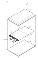
- FIG. 1 is an exploded perspective view of a nonaqueous electrolyte secondary battery according to a first embodiment of the present invention.
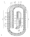
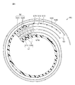
- FIG. 2 is a cross-sectional view taken along line II-II in FIG. It is sectional drawing to which a part of FIG. 2 was expanded. It is sectional drawing of the nonaqueous electrolyte secondary battery which concerns on the 2nd Embodiment of this invention. It is sectional drawing which cut
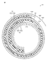
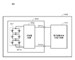
- FIG. 8 is a block diagram of an electronic device as an application example. 1 is a cross-sectional view of a wound electrode body having a normal structure 1. FIG.
- Embodiments of the present invention will be described in the following order. 1 First Embodiment (Example of Laminated Film Type Battery) 2 Second Embodiment (Example of Cylindrical Battery) 3 Third Embodiment (Example of Battery Pack and Electronic Device)
- a nonaqueous electrolyte secondary battery (hereinafter simply referred to as “battery”) 10 is a so-called laminate film type battery, and includes a positive electrode lead 11 and a negative electrode lead 12.
- the flat wound electrode body 20 to which is attached is housed inside the film-shaped exterior member 30 and can be reduced in size, weight, and thickness.
- the battery 10 is, for example, a so-called lithium ion secondary battery in which the capacity of the negative electrode is represented by a capacity component due to insertion and extraction of lithium (Li) that is an electrode reactant.
- the positive electrode lead 11 and the negative electrode lead 12 are led out from the inside of the exterior member 30 to the outside, for example, in the same direction.
- the positive electrode lead 11 and the negative electrode lead 12 are made of a metal material such as aluminum (Al), copper (Cu), nickel (Ni), or stainless steel, respectively, and each have a thin plate shape or a mesh shape.
- the exterior material 30 is made of, for example, a flexible laminate film.
- the packaging material 30 has a configuration in which, for example, a heat-sealing resin layer, a metal layer, and a surface protective layer are sequentially laminated.
- the surface on the heat sealing resin layer side is a surface on the side where the wound electrode body 20 is accommodated.
- the material for the heat-sealing resin layer include polypropylene (PP) and polyethylene (PE).
- the material for the metal layer include aluminum.
- Examples of the material for the surface protective layer include nylon (Ny).
- the exterior member 30 is made of a rectangular aluminum laminated film in which, for example, a nylon film, an aluminum foil, and a polyethylene film are bonded together in this order.
- the exterior material 30 is disposed so that the heat-sealing resin layer side and the wound electrode body 20 face each other, and the outer edge portions are in close contact with each other by fusion or an adhesive.
- An adhesion film 31 is inserted between the outer packaging material 30 and the positive electrode lead 11 and the negative electrode lead 12 to prevent intrusion of outside air.
- the adhesion film 31 is made of a material having adhesion to the positive electrode lead 11 and the negative electrode lead 12, for example, a polyolefin resin such as polyethylene, polypropylene, modified polyethylene, or modified polypropylene.
- the exterior material 30 may be made of a laminated film having another structure, a polymer film such as polypropylene, or a metal film instead of the above-described laminated film.
- a laminate film in which an aluminum film is used as a core and a polymer film is laminated on one or both sides thereof may be used.
- a coloring material is included in at least 1 layer chosen from the thing further provided with a colored layer and / or a heat-fusion resin layer and a surface protective layer.
- a thing may be used.
- the adhesive layer may include a coloring material.
- the wound electrode body 20 as a battery element is formed by laminating a strip-like positive electrode 21 and a strip-like negative electrode 22 via a strip-like separator 23 and an electrolyte layer 24, The outermost peripheral part is protected by a protective tape (not shown).
- a protective tape not shown
- FIG. 2 in order to facilitate understanding of the winding structure of the wound electrode body 20, the illustration of the electrolyte layer 24 is omitted and a gap is provided between the constituent members of the wound electrode body 20. ing.
- the positive electrode 21, the negative electrode 22, the separator 23, and the electrolyte layer 24 constituting the wound electrode body 20 will be described in order.
- the positive electrode 21 includes a positive electrode current collector 21A and a positive electrode active material layer 21B provided on both surfaces of the positive electrode current collector 21A.
- the positive electrode current collector 21A is made of, for example, a metal foil such as an aluminum foil, a nickel foil, or a stainless steel foil.
- the positive electrode active material layer 21B includes, for example, a positive electrode active material capable of inserting and extracting lithium as an electrode reactant, a binder, and a conductive agent.
- lithium-containing compounds such as lithium oxide, lithium phosphorous oxide, lithium sulfide, or an intercalation compound containing lithium are suitable. You may mix and use the above.
- a lithium-containing compound containing lithium, a transition metal element, and oxygen (O) is preferable.
- lithium-containing compounds include lithium composite oxides having a layered rock salt type structure shown in Formula (A), lithium composite phosphates having an olivine type structure shown in Formula (B), and the like. Can be mentioned.
- the lithium-containing compound is more preferably one containing at least one member selected from the group consisting of cobalt (Co), nickel, manganese (Mn), and iron (Fe) as a transition metal element.
- Examples of such a lithium-containing compound include a lithium composite oxide having a layered rock salt type structure represented by the formula (C), formula (D), or formula (E), and a spinel type compound represented by the formula (F). Examples thereof include a lithium composite oxide having a structure, or a lithium composite phosphate having an olivine structure shown in the formula (G).
- LiNi 0.50 Co 0.20 Mn 0.30 O 2 Li a CoO 2 (A ⁇ 1), Li b NiO 2 (b ⁇ 1), Li c1 Ni c2 Co 1-c2 O 2 (c1 ⁇ 1, 0 ⁇ c2 ⁇ 1), Li d Mn 2 O 4 (d ⁇ 1) or Li e FePO 4 (e ⁇ 1) and the like.
- M1 represents at least one element selected from Groups 2 to 15 excluding nickel and manganese.
- X represents at least one of Group 16 and Group 17 elements other than oxygen.
- P, q, y, z are 0 ⁇ p ⁇ 1.5, 0 ⁇ q ⁇ 1.0, 0 ⁇ r ⁇ 1.0, ⁇ 0.10 ⁇ y ⁇ 0.20, 0 ⁇ (The value is within the range of z ⁇ 0.2.)
- M2 represents at least one element selected from Group 2 to Group 15.
- a and b are 0 ⁇ a ⁇ 2.0 and 0.5 ⁇ b ⁇ 2.0. It is a value within the range.
- M3 is cobalt, magnesium (Mg), aluminum, boron (B), titanium (Ti), vanadium (V), chromium (Cr), iron, copper, zinc (Zn), It represents at least one member selected from the group consisting of zirconium (Zr), molybdenum (Mo), tin (Sn), calcium (Ca), strontium (Sr), and tungsten (W), f, g, h, j, and k.
- M4 is at least one selected from the group consisting of cobalt, manganese, magnesium, aluminum, boron, titanium, vanadium, chromium, iron, copper, zinc, molybdenum, tin, calcium, strontium, and tungsten.
- M, n, p and q are 0.8 ⁇ m ⁇ 1.2, 0.005 ⁇ n ⁇ 0.5, ⁇ 0.1 ⁇ p ⁇ 0.2, 0 ⁇ q ⁇ 0. (The value is within a range of 1.
- the composition of lithium varies depending on the state of charge and discharge, and the value of m represents a value in a fully discharged state.
- M5 is at least one selected from the group consisting of nickel, manganese, magnesium, aluminum, boron, titanium, vanadium, chromium, iron, copper, zinc, molybdenum, tin, calcium, strontium, and tungsten.
- Represents one, r, s, t and u are 0.8 ⁇ r ⁇ 1.2, 0 ⁇ s ⁇ 0.5, ⁇ 0.1 ⁇ t ⁇ 0.2, 0 ⁇ u ⁇ 0.1 (Note that the composition of lithium varies depending on the state of charge and discharge, and the value of r represents the value in a fully discharged state.)
- M6 is at least one selected from the group consisting of cobalt, nickel, magnesium, aluminum, boron, titanium, vanadium, chromium, iron, copper, zinc, molybdenum, tin, calcium, strontium, and tungsten.
- V, w, x, and y are 0.9 ⁇ v ⁇ 1.1, 0 ⁇ w ⁇ 0.6, 3.7 ⁇ x ⁇ 4.1, and 0 ⁇ y ⁇ 0.1. (Note that the lithium composition varies depending on the state of charge and discharge, and the value of v represents a value in a fully discharged state.)
- Li z M7PO 4 (G) (In the formula (G), M7 is composed of cobalt, manganese, iron, nickel, magnesium, aluminum, boron, titanium, vanadium, niobium (Nb), copper, zinc, molybdenum, calcium, strontium, tungsten and zirconium. Represents at least one member of the group, z is a value in the range of 0.9 ⁇ z ⁇ 1.1, wherein the composition of lithium varies depending on the state of charge and discharge, and the value of z is a fully discharged state Represents the value at.)
- examples of the positive electrode active material capable of inserting and extracting lithium include inorganic compounds containing no lithium, such as MnO 2 , V 2 O 5 , V 6 O 13 , NiS, and MoS.
- the positive electrode active material capable of inserting and extracting lithium may be other than the above.
- the positive electrode active material illustrated above may be mixed 2 or more types by arbitrary combinations.
- the binder includes a fluorine-based binder having a melting point of 166 ° C. or lower.
- the melting point of the fluorine-based binder is 166 ° C. or less, the affinity between the fluorine-based binder and the positive electrode active material particles is improved, and the positive electrode active material particles can be satisfactorily coated with the fluorine-based binder.
- the reaction between the particles and the electrolytic solution can be suppressed. Therefore, swelling of the battery 10 due to gas generation can be suppressed.
- the thermal stability of the positive electrode 21 can be improved by coating the positive electrode active material particles well with a fluorine-based binder, the safety of the battery 10 (for example, short-circuit safety evaluated by a nail penetration test) It is also possible to improve the heating system safety evaluated by the heating test.
- fusing point of a fluorine-type binder is not specifically limited, For example, it is 150 degreeC or more.
- the melting point of the above fluorine-based binder is measured, for example, as follows. First, the positive electrode 21 is taken out from the battery 10, washed with dimethyl carbonate (DMC) and dried, and then the positive electrode current collector 21A is removed and heated and stirred in an appropriate dispersion medium (for example, N-methylpyrrolidone). Then, the binder is dissolved in the dispersion medium. Thereafter, the positive electrode active material is removed by centrifugation, the supernatant is filtered, and then evaporated to dryness or reprecipitated in water, whereby the binder can be taken out.
- DMC dimethyl carbonate
- an appropriate dispersion medium for example, N-methylpyrrolidone
- DSC differential scanning calorimeter, for example, Rigaku Co., Ltd. Rigaku Thermo plus DSC8230
- the temperature at which the polymer becomes fluid by heating and heating is defined as the melting point.
- the fluorine-based binder is, for example, polyvinylidene fluoride (PVdF).
- PVdF polyvinylidene fluoride
- the polyvinylidene fluoride it is preferable to use a homopolymer containing a vinylidene fluoride (VdF) as a monomer.
- the polyvinylidene fluoride it is possible to use a copolymer (copolymer) containing vinylidene fluoride (VdF) as a monomer.
- polyvinylidene fluoride which is a copolymer, easily swells and dissolves in an electrolytic solution. Since the binding force is weak, the characteristics of the positive electrode 21 may be deteriorated.
- polyvinylidene fluoride one obtained by modifying a part of the terminal or the like with a carboxylic acid such as maleic acid may be used.
- carboxylic acid such as maleic acid
- PTFE polytetrafluoroethylene
- binder synthetic rubber (fluoro rubber) may be used instead of the fluorine-based binder.
- the content of the fluorine-based binder in the positive electrode active material layer 21B is 0.5% by mass or more and 2.8% by mass or less, preferably 0.7% by mass or more and 2.8% by mass or less.
- the content of the fluorine-based binder is less than 0.5% by mass, the binding between the positive electrode active material particles and the binding between the positive electrode active material particles and the positive electrode current collector 21A become insufficient.
- the positive electrode active material layer 21B may fall off from the positive electrode current collector 21A.
- the coating of the positive electrode active material particles with the fluorine-based binder becomes insufficient, and it becomes difficult to suppress the swelling of the battery 10, and the safety of the battery 10 may be reduced.
- the content of the fluorine-based binder exceeds 2.8% by mass, the flexibility of the positive electrode active material layer 21B decreases, and when the positive electrode 21 is wound in a flat shape, the positive electrode active material layer 21B is cracked. May occur.
- the content of the above-mentioned fluorine-based binder is measured, for example, as follows. First, the positive electrode 21 is taken out from the battery 10, washed with DMC, and dried. Next, using a differential thermal balance apparatus (TG-DTA, for example, Rigaku Thermo plus TG8120 manufactured by Rigaku Co., Ltd.), a sample of several to several tens of mg is 600 in an air atmosphere at a heating rate of 1 to 5 ° C./min. The content of the fluorine-based binder in the positive electrode active material layer 21B is obtained from the weight reduction amount at that time.
- TG-DTA differential thermal balance apparatus
- the amount of weight loss due to the binder is determined by isolating the binder as described in the method for measuring the melting point of the binder, and performing TG-DTA measurement of the binder alone in an air atmosphere. It can be confirmed by examining how many degrees Celsius burns.
- the conductive agent examples include carbon materials such as graphite, carbon fiber, carbon black, ketjen black, and carbon nanotube. One of these may be used alone, or two or more may be mixed. May be used. In addition to the carbon material, a metal material or a conductive polymer material may be used as long as it is a conductive material.
- the content of the conductive agent in the positive electrode active material layer 21B is preferably 0.3% by mass or more and 2.8% by mass or less, and more preferably 0.5% by mass or more and 2.8% by mass or less. .
- the content of the conductive agent is 0.3% by mass or more, the gas absorption ability by the conductive agent is improved, and the swelling of the battery 10 can be further suppressed.
- flexibility of the positive electrode active material layer 21B can be improved, and when the positive electrode 21 is wound flatly, it can suppress that a crack generate
- the content of the conductive agent is 2.8% by mass or less, the amount of the binder adsorbed on the conductive agent is suppressed, and when the positive electrode 21 is wound in a flat shape, the positive electrode active material 21A is activated by the positive electrode active material 21A. It is possible to suppress the material layer 21B from falling off. In addition, by suppressing the amount of the binder adsorbed on the conductive agent, it is possible to suppress insufficient coverage of the positive electrode active material particles with the binder. Therefore, it can suppress that the safety
- the content of the conductive agent is measured, for example, as follows. First, the positive electrode 21 is taken out from the battery 10, washed with DMC, and dried. Next, using a differential thermal balance apparatus (TG-DTA, for example, Rigaku Thermo plus TG8120 manufactured by Rigaku Co., Ltd.), a sample of several to several tens of mg is 600 in an air atmosphere at a heating rate of 1 to 5 ° C./min. Heat to ° C. And the content of a conductive agent is calculated
- TG-DTA differential thermal balance apparatus
- the amount of weight loss due to the binder is determined by isolating the binder as described in the method for measuring the melting point of the binder, and performing TG-DTA measurement of the binder alone in an air atmosphere. It can be confirmed by examining how many degrees Celsius burns.
- the negative electrode 22 has a structure in which a negative electrode active material layer 22B is provided on one surface or both surfaces of a negative electrode current collector 22A, and the negative electrode active material layer 22B and the positive electrode active material layer 21B are arranged to face each other. Yes. Although not shown, the negative electrode active material layer 22B may be provided only on one surface of the negative electrode current collector 22A.
- the negative electrode current collector 22A is made of, for example, a metal foil such as a copper foil, a nickel foil, or a stainless steel foil.
- the negative electrode active material layer 22B includes one or more negative electrode active materials capable of inserting and extracting lithium.
- the negative electrode active material layer 22B may further include additives such as a binder and a conductive agent as necessary.
- the electrochemical equivalent of the negative electrode 22 or the negative electrode active material is larger than the electrochemical equivalent of the positive electrode 21.
- lithium metal does not precipitate on the negative electrode 22 during charging. It is preferable.
- Negative electrode active material examples include carbon materials such as non-graphitizable carbon, graphitizable carbon, graphite, pyrolytic carbons, cokes, glassy carbons, organic polymer compound fired bodies, carbon fibers, and activated carbon. Is mentioned.
- examples of the coke include pitch coke, needle coke, and petroleum coke.
- An organic polymer compound fired body is a carbonized material obtained by firing a polymer material such as a phenol resin or a furan resin at an appropriate temperature, and part of it is non-graphitizable carbon or graphitizable carbon.
- These carbon materials are preferable because the change in crystal structure that occurs during charge and discharge is very small, a high charge and discharge capacity can be obtained, and good cycle characteristics can be obtained.
- graphite is preferable because it has a high electrochemical equivalent and can provide a high energy density.
- non-graphitizable carbon is preferable because excellent cycle characteristics can be obtained.
- a battery having a low charge / discharge potential specifically, a battery having a charge / discharge potential close to that of lithium metal is preferable because a high energy density of the battery 10 can be easily realized.
- a material containing at least one of a metal element and a metalloid element as a constituent element for example, an alloy, a compound, or a mixture
- a high energy density can be obtained by using such a material.
- the use with a carbon material is more preferable because a high energy density can be obtained and excellent cycle characteristics can be obtained.
- alloys include those containing one or more metal elements and one or more metalloid elements in addition to those composed of two or more metal elements.
- the nonmetallic element may be included.
- Examples of such a negative electrode active material include a metal element or a metalloid element capable of forming an alloy with lithium.
- a metal element or a metalloid element capable of forming an alloy with lithium.
- magnesium, boron, aluminum, titanium, gallium (Ga), indium (In), silicon (Si), germanium (Ge), tin, lead (Pb), bismuth (Bi), cadmium (Cd), Silver (Ag), zinc, hafnium (Hf), zirconium, yttrium (Y), palladium (Pd), or platinum (Pt) can be used. These may be crystalline or amorphous.
- the negative electrode active material those containing a 4B group metal element or semi-metal element in the short-period type periodic table as a constituent element are preferable, and more preferable are those containing at least one of silicon and tin as a constituent element. This is because silicon and tin have a large ability to occlude and release lithium, and a high energy density can be obtained.
- Examples of such a negative electrode active material include a simple substance, an alloy or a compound of silicon, a simple substance, an alloy or a compound of tin, or a material having one or more phases thereof at least in part.
- Examples of the silicon alloy include, as the second constituent element other than silicon, tin, nickel, copper, iron, cobalt, manganese, zinc, indium, silver, titanium, germanium, bismuth, antimony (Sb), and chromium.
- the thing containing at least 1 sort (s) of a group is mentioned.
- As an alloy of tin for example, as a second constituent element other than tin, among the group consisting of silicon, nickel, copper, iron, cobalt, manganese, zinc, indium, silver, titanium, germanium, bismuth, antimony and chromium The thing containing at least 1 sort (s) of these is mentioned.
- tin compound or silicon compound examples include those containing oxygen or carbon, and may contain the second constituent element described above in addition to tin or silicon.
- Examples of other negative electrode active materials include metal oxides or polymer compounds that can occlude and release lithium.
- Examples of the metal oxide include lithium titanium oxide containing titanium and lithium such as lithium titanate (Li 4 Ti 5 O 12 ), iron oxide, ruthenium oxide, or molybdenum oxide.
- Examples of the polymer compound include polyacetylene, polyaniline, polypyrrole, and the like.
- Binder for example, at least one selected from resin materials such as polyvinylidene fluoride, polytetrafluoroethylene, polyacrylonitrile, styrene butadiene rubber and carboxymethyl cellulose, and copolymers mainly composed of these resin materials is used. It is done.
- the same carbon material as that of the positive electrode active material layer 21B can be used.
- the separator 23 separates the positive electrode 21 and the negative electrode 22 and allows lithium ions to pass through while preventing a short circuit of current due to contact between the two electrodes.
- the separator 23 is made of, for example, a porous film made of a resin such as polytetrafluoroethylene, polypropylene, or polyethylene, and may have a structure in which two or more kinds of these porous films are laminated.
- a porous film made of polyolefin is preferable because it has an excellent short-circuit prevention effect and can improve the safety of the battery 10 due to a shutdown effect.
- polyethylene is preferable as a material constituting the separator 23 because it can obtain a shutdown effect within a range of 100 ° C.
- the porous film may have a structure of three or more layers in which a polypropylene layer, a polyethylene layer, and a polypropylene layer are sequentially laminated.
- the positive electrode active material layer 21B is not provided on the inner side surface of the outer peripheral side end portion of the positive electrode 21, but the positive electrode current collector exposed portion 21C 1 in which the inner side surface of the positive electrode current collector 21A is exposed is provided. Further, on the outer surface of the outer peripheral side end portion of the positive electrode 21, not the cathode active material layer 21B is provided, the cathode current collector exposed portion 21D 1 is provided with an outer surface of the cathode current collector 21A is exposed.
- the length of the positive electrode current collector exposed portion 21D 1 in the winding direction is, for example, about one cycle longer than the length of the positive electrode current collector exposed portion 21C 1 in the winding direction.
- the step portion at the boundary between the positive electrode current collector exposed portion 21C 1 and the positive electrode active material layer 21B and the positive electrode current collector exposed portion 21C 1 are covered with the protective tape 25A 1 . Further, the step portion at the boundary between the positive electrode current collector exposed portion 21D 1 and the positive electrode active material layer 21B and the positive electrode current collector exposed portion 21D 1 are covered with the protective tape 25B 1 .
- the positive electrode active material layer 21 ⁇ / b > B is not provided on the inner side surface of the inner peripheral side end of the positive electrode 21, but the positive electrode current collector exposed portion 21 ⁇ / b > C 2 where the inner side surface of the positive electrode current collector 21 ⁇ / b > A is exposed is provided. Further, on the outer surface of the inner peripheral end of the positive electrode 21, not the cathode active material layer 21B is provided, the cathode current collector exposed portion 21D 2 in which the outer surface is exposed cathode current collector 21A is provided .
- the lengths of the positive electrode current collector exposed portions 21C 2 and 21D 2 in the winding direction are, for example, substantially the same.
- the positive electrode lead 11 to the cathode current collector exposed portion 21C 2 are connected.
- the step portion at the boundary between the positive electrode current collector exposed portion 21C 2 and the positive electrode active material layer 21B and the positive electrode current collector exposed portion 21C 2 are covered with the protective tape 25A 2 .
- the step portion at the boundary between the positive electrode current collector exposed portion 21D 2 and the positive electrode active material layer 21B and the positive electrode current collector exposed portion 21D 2 are covered with the protective tape 25B 2 .
- the negative electrode active material layer 22 ⁇ / b> B is not provided on the inner side surface of the outer peripheral side end of the negative electrode 22, but the negative electrode current collector exposed portion 22 ⁇ / b> C 1 where the inner side surface of the negative electrode current collector 22 ⁇ / b> A is exposed is provided. Further, on the outer surface of the outer peripheral side end portion of the anode 22, not the anode active material layer 22B is provided, the negative electrode current collector exposed portion 22D 1 in which the outer surface is exposed in the anode current collector 22A.
- the lengths of the negative electrode current collector exposed portions 22C 1 and 22D 1 in the winding direction are, for example, substantially the same.
- the length of the negative electrode current collector exposed portion 22C 2 in the winding direction is, for example, approximately one turn longer than the length of the negative electrode current collector exposed portion 22D 2 in the winding direction.
- the negative electrode current collector exposed portion 22D 2 anode lead 12 is connected.
- a protective tape 26A is provided at a portion of the negative electrode current collector exposed portion 22C 2 that faces the tip on the inner peripheral side of the positive electrode current collector 21A. Further, a protective tape 26B is provided in a portion of the negative electrode current collector exposed portion 22D 2 that faces the tip on the inner peripheral side of the positive electrode current collector 21A. Note that the protective tapes 25A 1 , 25A 2 , 25B 1 , 25B 2 , 26A, and 26B are provided as necessary and need not be provided.
- a first facing portion is configured.
- a positive electrode current collector exposed portion 21D 1 provided at the outer peripheral side end portion of the positive electrode 21 and a negative electrode current collector exposed portion 22C 1 provided at the outer peripheral side end portion of the negative electrode 22 are interposed via the separator 23. It constitutes a second opposing portion that faces each other.
- a positive electrode current collector exposed portion 21C 2 provided at the inner peripheral side end portion of the positive electrode 21 and a negative electrode current collector exposed portion 22D 2 provided at the inner peripheral side end portion of the negative electrode 22 are interposed via the separator 23. It constitutes a third facing portion that faces each other.
- a fourth facing portion that faces each other is formed.
- the first to fourth facing portions are preferably provided at least in the central portion of the flat surface 20S in the winding direction from the viewpoint of improving safety.
- the first to fourth facing portions are preferably provided across at least one flat surface 20S in the winding direction from the viewpoint of further improving safety, and at least two flat portions in the winding direction. More preferably, it is provided over the surface 20S.
- the length of the first to fourth facing portions in the winding direction is preferably 1/4 or more, more preferably more than the length of the flat surface 20S in the winding direction. More preferably, it is provided over a range of half or more, particularly preferably one or more.
- the lengths of the first to fourth opposing portions in the winding direction are preferably 2 turns or less, more preferably 1 turn or less, and even more preferably 1 turn or less from the viewpoint of suppressing a decrease in energy density. It is provided over a range.
- the electrolyte layer 24 is an example of an intermediate layer, and includes a non-aqueous electrolyte and a fluororesin as a polymer compound that serves as a holding body that holds the non-aqueous electrolyte. It is swollen. The content ratio of the fluororesin can be adjusted as appropriate.
- the electrolyte layer 24 is preferably a gel electrolyte layer. This is because when the electrolyte layer 24 is a gel electrolyte layer, high ion conductivity can be obtained, and leakage of the battery 10 can be particularly suppressed.
- the electrolytic solution includes a solvent and an electrolyte salt dissolved in the solvent.
- the electrolytic solution may contain a known additive in order to improve battery characteristics.
- cyclic carbonate such as ethylene carbonate or propylene carbonate
- the solvent in addition to these cyclic carbonates, it is preferable to use a mixture of chain carbonates such as diethyl carbonate, dimethyl carbonate, ethylmethyl carbonate or methylpropyl carbonate. This is because high ionic conductivity can be obtained.
- the solvent preferably further contains 2,4-difluoroanisole or vinylene carbonate. This is because 2,4-difluoroanisole can improve discharge capacity, and vinylene carbonate can improve cycle characteristics. Therefore, it is preferable to use a mixture of these because the discharge capacity and cycle characteristics can be improved.
- examples of the solvent include butylene carbonate, ⁇ -butyrolactone, ⁇ -valerolactone, 1,2-dimethoxyethane, tetrahydrofuran, 2-methyltetrahydrofuran, 1,3-dioxolane, 4-methyl-1,3- Dioxolane, methyl acetate, methyl propionate, acetonitrile, glutaronitrile, adiponitrile, methoxyacetonitrile, 3-methoxypropironitrile, N, N-dimethylformamide, N-methylpyrrolidinone, N-methyloxazolidinone, N, N-dimethyl Examples include imidazolidinone, nitromethane, nitroethane, sulfolane, dimethyl sulfoxide, and trimethyl phosphate.
- a compound obtained by substituting at least a part of hydrogen in these non-aqueous solvents with fluorine may be preferable because the reversibility of the electrode reaction may be improved depending on the type of electrode to be combined.
- lithium salt As electrolyte salt, lithium salt is mentioned, for example, 1 type may be used independently, and 2 or more types may be mixed and used for it.
- Lithium salts include LiPF 6 , LiBF 4 , LiAsF 6 , LiClO 4 , LiB (C 6 H 5 ) 4 , LiCH 3 SO 3 , LiCF 3 SO 3 , LiN (SO 2 CF 3 ) 2 , LiC (SO 2 CF 3 ) 3 , LiAlCl 4 , LiSiF 6 , LiCl, difluoro [oxolato-O, O ′] lithium borate, lithium bisoxalate borate, or LiBr.
- LiPF 6 is preferable because it can obtain high ion conductivity and can improve cycle characteristics.
- the fluororesin as the polymer compound includes, for example, at least one of polyvinylidene fluoride, a copolymer of vinylidene fluoride and hexafluoropropylene, polytetrafluoroethylene, and polyhexafluoropropylene.
- polyvinylidene fluoride a copolymer of vinylidene fluoride and hexafluoropropylene
- polytetrafluoroethylene polytetrafluoroethylene
- polyhexafluoropropylene polyhexafluoropropylene.
- the open circuit voltage (that is, the battery voltage) in the fully charged state per pair of the positive electrode 21 and the negative electrode 22 may be less than 4.25V, preferably 4.25V or more. It may be designed to be preferably 4.3V, and even more preferably 4.4V or more. By increasing the battery voltage, a high energy density can be obtained.
- the upper limit value of the open circuit voltage in the fully charged state per pair of positive electrode 21 and negative electrode 22 is preferably 6.00 V or less, more preferably 4.60 V or less, and even more preferably 4.50 V or less.
- the positive electrode 21 is produced as follows. First, for example, a positive electrode active material, a conductive agent, and a binder are mixed to prepare a positive electrode mixture, and the positive electrode mixture is dispersed in a solvent such as N-methyl-2-pyrrolidone (NMP) to form a paste. A positive electrode mixture slurry is prepared. Next, this positive electrode mixture slurry is applied to the positive electrode current collector 21 ⁇ / b> A, the solvent is dried, and the positive electrode active material layer 21 ⁇ / b> B is formed by compression molding with a roll press or the like, thereby forming the positive electrode 21.
- NMP N-methyl-2-pyrrolidone
- the negative electrode 22 is produced as follows. First, for example, a negative electrode active material and a binder are mixed to prepare a negative electrode mixture, and this negative electrode mixture is dispersed in a solvent such as N-methyl-2-pyrrolidone to prepare a paste-like negative electrode mixture slurry. To do. Next, the negative electrode mixture slurry is applied to the negative electrode current collector 22A, the solvent is dried, and the negative electrode active material layer 22B is formed by compression molding with a roll press or the like, thereby producing the negative electrode 22.
- a solvent such as N-methyl-2-pyrrolidone
- the electrolyte layer 24 is produced as follows. First, an electrolyte solution containing a matrix polymer, an electrolytic solution, and a dilution solvent is prepared. Next, this electrolyte solution is uniformly applied and impregnated on each of the positive electrode 21 and the negative electrode 22 obtained as described above. Thereafter, the electrolyte layer 24 is formed by evaporating and removing the diluted solvent.
- the wound electrode body 20 is manufactured as follows. First, the positive electrode lead 11 is attached to the end of the positive electrode current collector 21A by welding, and the negative electrode lead 12 is attached to the end of the negative electrode current collector 22A by welding. Next, the positive electrode 21 and the negative electrode 22 on which the electrolyte layer 24 is formed are laminated through a separator 23 to form a laminated body, and then the laminated body is wound in the longitudinal direction, and the protective tape 25 is attached to the outermost peripheral portion.
- the wound electrode body 20 is formed by bonding.
- the wound electrode body 20 is sealed with the exterior material 30 as follows. First, for example, the wound electrode body 20 is sandwiched between flexible packaging materials 30, and the outer edges of the packaging material 30 are brought into close contact with each other by thermal fusion or the like and sealed. At that time, an adhesive film 31 is inserted between the positive electrode lead 11 and the negative electrode lead 12 and the exterior material 30. The adhesion film 31 may be attached in advance to each of the positive electrode lead 11 and the negative electrode lead 12. Further, the exterior member 30 may be embossed in advance to form a concave portion as an accommodation space for accommodating the wound electrode body 20. Thus, the battery 10 in which the wound electrode body 20 is accommodated by the exterior material 30 is obtained.
- the battery 10 is molded by heat pressing as necessary. More specifically, the battery 10 is heated at a temperature higher than normal temperature while being pressurized. Next, if necessary, a pressure plate or the like is pressed against the main surface of the battery 10 to press the battery 10 uniaxially.
- the battery 10 according to the first embodiment can improve the safety of the battery 10 by including both of the following configurations (A) and (B). Further, swelling of the battery 10 due to gas generation can be suppressed. Moreover, when the positive electrode 21 is wound in a flat shape, it is possible to suppress the positive electrode active material layer 21B from falling off the positive electrode current collector 21A and to suppress the occurrence of cracks in the positive electrode active material layer 21B. it can.
- reaction leading to thermal runaway is considered to explode when a certain temperature is exceeded.
- Reaction suppression is mainly a mechanism for improving the safety of the positive electrode, but if it is placed in a slightly severe situation, the reaction proceeds at a stretch and leads to thermal runaway.
- Exceeding or not exceeding a certain temperature is the applied energy, that is, in this case, Joule heat generated by a short circuit. Therefore, by suppressing the Joule heat generation, it became possible to simultaneously cope with the “situation in which reaction is unlikely to occur” and “suppression of applied energy”, which were performed at the same time as the effect of adding each effect independently. This is presumed to be the mechanism that led to a significant improvement.
- the battery 40 according to the second embodiment of the present invention is a so-called cylindrical type, and a pair of belt-like batteries inside a substantially hollow cylindrical battery can (exterior material) 41.
- the positive electrode 51 and the strip-shaped negative electrode 52 have the wound electrode body 20 wound after being laminated via the separator 53.
- the battery can 41 is made of nickel-plated iron or aluminum, and has one end closed and the other end open.
- an electrolytic solution as a liquid electrolyte is injected and impregnated in the positive electrode 51, the negative electrode 52, and the separator 53.
- a pair of insulating plates 42 and 43 are respectively disposed perpendicular to the winding peripheral surface so as to sandwich the winding electrode body 50.
- the electrolytic solution is the same as the electrolytic solution in the first embodiment.
- a battery cover 44, a safety valve mechanism 45 and a heat sensitive resistance element (Positive Temperature Coefficient; PTC element) 46 provided inside the battery cover 44 are interposed via a sealing gasket 47. It is attached by caulking. Thereby, the inside of the battery can 41 is sealed.
- the battery lid 44 is made of the same material as the battery can 41, for example.
- the safety valve mechanism 45 is electrically connected to the battery lid 44, and when the internal pressure of the battery exceeds a certain level due to an internal short circuit or external heating, the disk plate 15A is reversed and wound with the battery lid 44. The electrical connection with the rotating electrode body 50 is cut off.
- the sealing gasket 47 is made of, for example, an insulating material, and the surface thereof is coated with asphalt.
- a center pin 54 is inserted in the center of the wound electrode body 50.
- a positive electrode lead 55 made of aluminum or the like is connected to the positive electrode 51 of the spirally wound electrode body 50, and a negative electrode lead 56 made of nickel or the like is connected to the negative electrode 52.
- the positive electrode lead 55 is electrically connected to the battery lid 44 by being welded to the safety valve mechanism 45, and the negative electrode lead 56 is welded and electrically connected to the battery can 41.
- the positive electrode 51 includes a positive electrode current collector 51A and positive electrode active material layers 51B provided on both surfaces of the positive electrode current collector 51A.
- the negative electrode 52 includes a negative electrode current collector 52A and a negative electrode active material layer 52B provided on both surfaces of the negative electrode current collector 52A.
- the configurations of the positive electrode current collector 51A, the positive electrode active material layer 51B, the negative electrode current collector 52A, and the negative electrode active material layer 52B are respectively the positive electrode current collector 21A, the positive electrode active material layer 21B, and the negative electrode current collector in the first embodiment. This is the same as 22A and the negative electrode active material layer 22B.
- the positive electrode active material layer 51B is not provided on the inner side surface of the outer peripheral side end portion of the positive electrode 51, but the positive electrode current collector exposed portion 51C in which the inner side surface of the positive electrode current collector 51A is exposed is provided. Further, the positive electrode active material layer 51B is not provided on the outer side surface of the outer peripheral side end portion of the positive electrode 51, and the positive electrode current collector exposed portion 51D is provided in which the outer side surface of the positive electrode current collector 51A is exposed.
- the length of the positive electrode current collector exposed portion 51D in the winding direction is, for example, approximately one turn longer than the length of the positive electrode current collector exposed portion 51C in the winding direction.
- the step portion at the boundary between the positive electrode current collector exposed portion 51C and the positive electrode active material layer 51B is covered with a protective tape 57A. Further, the step portion at the boundary between the positive electrode current collector exposed portion 51D and the positive electrode active material layer 51B is covered with the protective tape 57B.
- a negative electrode active material layer 52B is not provided on the inner side surface of the outer peripheral side end portion of the negative electrode 52, and a negative electrode current collector exposed portion 52C in which the inner side surface of the negative electrode current collector 52A is exposed is provided.
- the negative electrode active material layer 52B is not provided on the outer surface of the outer peripheral side end of the negative electrode 52, and a negative electrode current collector exposed portion 52D in which the outer surface of the negative electrode current collector 52A is exposed is provided.
- the lengths of the negative electrode current collector exposed portions 52C and 52D in the winding direction are substantially the same, for example.
- a positive electrode current collector exposed portion 51D provided at the outer peripheral end portion of the positive electrode 51 and a negative electrode current collector exposed portion 52C provided at the outer peripheral end portion of the negative electrode 52 constitute a facing portion facing each other through the separator 53. is doing.
- the facing portion on the outer peripheral portion of the wound electrode body 50 it is possible to form a low-resistance short circuit in a trauma test such as a nail penetration test. Therefore, Joule heat generation at the time of a short circuit can be suppressed, and safety can be improved.
- the length of the facing portion in the winding direction is preferably 1/4 or more, more preferably half or more, particularly preferably 1 or more.
- the length of the facing portion in the winding direction is preferably provided over a range of two or less, more preferably one and a half or less, from the viewpoint of suppressing a decrease in energy density.
- the separator 53 has a configuration including a base material and a surface layer provided on one or both surfaces of the base material.
- the surface layer is an example of an intermediate layer, and includes inorganic particles having electrical insulation, and a resin material that binds the inorganic particles to the surface of the base material and binds the inorganic particles to each other.
- the surface layer is preferably provided on the surface facing the positive electrode 51. Since the separator 53 includes the above-described surface layer, adhesion between the positive electrode active material layer 21 ⁇ / b> B containing a fluorine-based binder having a melting point of 166 ° C. or less and the separator 53 can be increased, so that swelling of the battery 40 is suppressed. In addition, the safety of the battery 40 can be improved.
- the resin material contained in the surface layer may have, for example, a three-dimensional network structure in which the fibrils are fibrillated and the fibrils are continuously connected to each other.
- the inorganic particles can be maintained in a dispersed state without being connected to each other by being supported on the resin material having the three-dimensional network structure.
- the resin material may be bound to the surface of the base material or the inorganic particles without being fibrillated. In this case, higher binding properties can be obtained.
- the base material is a porous layer having porosity. More specifically, the base material is a porous film composed of an insulating film having a large ion permeability and a predetermined mechanical strength, and the electrolytic solution is held in the pores of the base material. It is preferable that the base material has a predetermined mechanical strength as a main part of the separator, while having a high resistance to an electrolytic solution, a low reactivity, and a property of being difficult to expand.
- the resin material constituting the base material it is preferable to use, for example, a polyolefin resin such as polypropylene or polyethylene, an acrylic resin, a styrene resin, a polyester resin, or a nylon resin.
- polyethylene such as low density polyethylene, high density polyethylene, linear polyethylene or the like, or a low molecular weight wax component thereof, or a polyolefin resin such as polypropylene is suitable because it has an appropriate melting temperature and is easily available.
- a material including a porous film made of a polyolefin resin is excellent in separability between the positive electrode 21 and the negative electrode 22 and can further reduce a decrease in internal short circuit.
- a non-woven fabric may be used as the base material.
- fibers constituting the nonwoven fabric aramid fibers, glass fibers, polyolefin fibers, polyethylene terephthalate (PET) fibers, nylon fibers, or the like can be used. Moreover, it is good also as a nonwoven fabric by mixing these 2 or more types of fibers.
- the inorganic particles include, for example, at least one of metal oxide, metal nitride, metal carbide, metal sulfide, and the like.
- Metal oxides are aluminum oxide (alumina, Al 2 O 3 ), boehmite (hydrated aluminum oxide), magnesium oxide (magnesia, MgO), titanium oxide (titania, TiO 2 ), zirconium oxide (zirconia, ZrO 2 ). , Silicon oxide (silica, SiO 2 ), yttrium oxide (yttria, Y 2 O 3 ) and the like.
- the metal nitride preferably contains at least one of silicon nitride (Si 3 N 4 ), aluminum nitride (AlN), boron nitride (BN), titanium nitride (TiN), and the like.
- the metal carbide preferably includes at least one of silicon carbide (SiC) and boron carbide (B 4 C).
- the metal sulfide preferably contains barium sulfate (BaSO 4 ) and the like.
- zeolite M 2 / n O ⁇ Al 2 O 3 ⁇ xSiO 2 ⁇ yH 2 O
- M represents a metal element
- x ⁇ 2, y ⁇ 0 porous aluminosilicates such as layered silicates, titanates
- It may contain at least one of minerals such as barium (BaTiO 3 ) and strontium titanate (SrTiO 3 ).
- the inorganic particles have oxidation resistance and heat resistance, and the surface layer on the side facing the positive electrode containing the inorganic particles has strong resistance to an oxidizing environment in the vicinity of the positive electrode during charging.
- the shape of the inorganic particles is not particularly limited, and any of spherical shape, plate shape, fiber shape, cubic shape, random shape, and the like can be used.
- the resin material constituting the surface layer examples include fluorine-containing resins such as polyvinylidene fluoride and polytetrafluoroethylene, fluorine-containing rubbers such as vinylidene fluoride-tetrafluoroethylene copolymer and ethylene-tetrafluoroethylene copolymer, and styrene.
- fluorine-containing resins such as polyvinylidene fluoride and polytetrafluoroethylene
- fluorine-containing rubbers such as vinylidene fluoride-tetrafluoroethylene copolymer and ethylene-tetrafluoroethylene copolymer
- styrene examples include polystyrene.
- resin materials may be used alone or in combination of two or more.
- fluorine resins such as polyvinylidene fluoride are preferable from the viewpoint of oxidation resistance and flexibility, and aramid or polyamideimide is preferably included from the viewpoint of heat resistance.
- the particle size of the inorganic particles is preferably in the range of 1 nm to 10 ⁇ m. If it is smaller than 1 nm, it is difficult to obtain, and even if it can be obtained, it is not worth the cost. On the other hand, if it is larger than 10 ⁇ m, the distance between the electrodes becomes large, and a sufficient amount of active material cannot be obtained in a limited space, resulting in a low battery capacity.
- a slurry composed of a matrix resin, a solvent and an inorganic substance is applied on a base material (porous membrane), and is passed through a poor solvent of the matrix resin and a solvate bath of the above solvent.
- a method of separating and then drying can be used.
- the inorganic particles described above may be contained in a porous film as a base material.
- the surface layer may be composed only of a resin material without containing inorganic particles.
- a fluororesin is used as the resin material. Even if the surface layer does not contain inorganic particles, the adhesion between the separator 53 and the positive electrode active material layer 51B containing a fluorine-based binder having a melting point of 166 ° C. or less is acceptable if the surface layer contains a fluororesin. Therefore, the safety of the battery 40 can be improved.
- Fluorine resins include melting point and glass transition temperature of fluorine-containing resins such as polyvinylidene fluoride and polytetrafluoroethylene, fluorine-containing rubbers such as vinylidene fluoride-tetrafluoroethylene copolymer and ethylene-tetrafluoroethylene copolymer. And a resin having at least one of 180 ° C. and higher heat resistance. These resin materials may be used alone or in combination of two or more.
- the present invention is applied to a cylindrical battery having a metal can as an exterior material.
- the present invention is applied to a laminated film battery, particularly a laminated film battery having a flat shape. It is preferable to do. This is due to the following reason. That is, in the case of a cylindrical battery, since the exterior material is a metal can, the battery is unlikely to swell. Moreover, since the wound electrode body has a cylindrical shape, the electrode is less likely to crack when the wound electrode body is wound. On the other hand, in a laminate film type battery, since the exterior material is a laminate film, the battery is likely to swell. Further, since the wound electrode body has a flat shape, the electrode is likely to be cracked when the wound electrode body is wound.
- FIG. 8 shows an example of the configuration of a battery pack 300 and an electronic device 400 as application examples.
- the electronic device 400 includes an electronic circuit 401 of the electronic device body and a battery pack 300.
- the battery pack 300 is electrically connected to the electronic circuit 401 via the positive terminal 331a and the negative terminal 331b.
- the electronic device 400 has a configuration in which the battery pack 300 is detachable by a user.
- the configuration of the electronic device 400 is not limited to this, and the battery pack 300 is built in the electronic device 400 so that the user cannot remove the battery pack 300 from the electronic device 400. May be.
- the positive terminal 331a and the negative terminal 331b of the battery pack 300 are connected to the positive terminal and the negative terminal of a charger (not shown), respectively.
- the positive terminal 331a and the negative terminal 331b of the battery pack 300 are connected to the positive terminal and the negative terminal of the electronic circuit 401, respectively.
- the electronic device 400 for example, a notebook personal computer, a tablet computer, a mobile phone (for example, a smartphone), a portable information terminal (Personal Digital Assistant: PDA), a display device (LCD, EL display, electronic paper, etc.), imaging Devices (eg, digital still cameras, digital video cameras, etc.), audio devices (eg, portable audio players), game devices, cordless phones, electronic books, electronic dictionaries, radios, headphones, navigation systems, memory cards, pacemakers, hearing aids, Electric tools, electric shavers, refrigerators, air conditioners, TVs, stereos, water heaters, microwave ovens, dishwashers, washing machines, dryers, lighting equipment, toys, medical equipment, robots, road conditioners, traffic lights, etc. It is, but not such limited thereto.
- the electronic circuit 401 includes, for example, a CPU, a peripheral logic unit, an interface unit, a storage unit, and the like, and controls the entire electronic device 400.
- the battery pack 300 includes an assembled battery 301 and a charge / discharge circuit 302.
- the battery pack 300 may further include an exterior material (not shown) that houses the assembled battery 301 and the charge / discharge circuit 302 as necessary.
- the assembled battery 301 is configured by connecting a plurality of secondary batteries 301a in series and / or in parallel.
- the plurality of secondary batteries 301a are connected, for example, in n parallel m series (n and m are positive integers).
- FIG. 8 shows an example in which six secondary batteries 301a are connected in two parallel three series (2P3S).
- the secondary battery 301a the battery according to the first or second embodiment described above is used.
- the battery pack 300 includes the assembled battery 301 including a plurality of secondary batteries 301 a
- the battery pack 300 includes a single secondary battery 301 a instead of the assembled battery 301. It may be adopted.
- the charging / discharging circuit 302 is a control unit that controls charging / discharging of the assembled battery 301. Specifically, during charging, the charging / discharging circuit 302 controls charging of the assembled battery 301. On the other hand, at the time of discharging (that is, when the electronic device 400 is used), the charging / discharging circuit 302 controls the discharging of the electronic device 400.
- the exterior material for example, a case made of metal, polymer resin, or a composite material thereof can be used.
- the composite material include a laminate in which a metal layer and a polymer resin layer are laminated.
- the spirally wound electrode body 20 includes a first opposing portion in which the positive electrode current collector exposed portion 21C 1 and the negative electrode current collector exposed portion 22D 1 face each other via the separator 23, and a positive electrode current collector.
- the configuration of the wound electrode body 20 is limited to this. It is not something.
- the wound electrode body 20 may include only the second facing portion as shown in FIG.
- the negative electrode active material layer 22B is not provided on the inner side surface of the outer peripheral side end portion of the negative electrode 22, but the negative electrode current collector exposed portion 22C 1 in which the inner side surface of the negative electrode current collector 22A is exposed is provided.
- the negative electrode active material layer 22B is provided on the outer surface of the outer peripheral side end portion of the negative electrode 22, and the outer surface of the negative electrode current collector 22A is not substantially exposed.
- the spirally wound electrode body 20 may include only the first facing portion.
- the wound electrode body 50 includes a positive electrode current collector exposed portion 51 ⁇ / b> D provided on the outer surface of the positive electrode 51 and a negative electrode current collector exposed portion 52 ⁇ / b> C provided on the inner surface of the negative electrode 52.
- the wound electrode body 50 includes a positive electrode current collector exposed portion 51 ⁇ / b> C provided on the inner surface of the positive electrode 51 and a negative electrode current collector exposed portion 52 ⁇ / b> D provided on the outer surface of the negative electrode 52.
- the positive electrode active material layer 51B may be provided on the outer surface of the outer peripheral side end of the positive electrode 51, and the outer surface of the positive electrode current collector 51A may be substantially unexposed.
- the opposing portion where the positive electrode current collector exposed portion and the negative electrode current collector exposed portion face each other with the separator 23 interposed therebetween is both the inner peripheral side end portion and the outer peripheral side end portion of the wound electrode body 20.
- it may be provided at either one of the inner peripheral side end and the outer peripheral side end of the spirally wound electrode body 20.
- the facing portions are provided at both the inner peripheral end and the outer peripheral end of the wound electrode body 20 as in the first embodiment. .
- the facing portion is provided on either the inner peripheral side end portion or the outer peripheral side end portion of the wound electrode body 20, from the viewpoint of improving safety, the facing portion is disposed on the outer periphery of the wound electrode body 20. It is preferable to provide at the side end. Further, the positions where the facing portions are provided are not limited to the inner peripheral side and outer peripheral side ends of the wound electrode body 20, but positions other than the inner peripheral side end and outer peripheral side ends, for example, the wound electrode body 20 You may make it provide in the middle peripheral part.
- the positive electrode active material layers 21 ⁇ / b> B and 51 ⁇ / b> B may contain a binder other than the fluorine-based binder as necessary.
- a binder other than the fluorine-based binder as necessary.
- resin materials such as polyacrylonitrile (PAN), styrene butadiene rubber (SBR), and carboxymethyl cellulose (CMC), and copolymers mainly composed of these resin materials. May be included.
- the positive electrode active material layers 21B and 51B may contain a fluorine-based binder other than polyvinylidene fluoride as necessary.
- a fluorine-based binder other than polyvinylidene fluoride as necessary.
- at least one of polytetrafluoroethylene (PTFE) and a VdF copolymer (copolymer) containing VdF as one of the monomers may be included.
- VdF copolymer examples include vinylidene fluoride (VdF) and at least one selected from the group consisting of hexafluoropropylene (HFP), chlorotrifluoroethylene (CTFE), tetrafluoroethylene (TFE), and the like. These copolymers can be used. More specifically, PVdF-HFP copolymer, PVdF-CTFE copolymer, PVdF-TFE copolymer, PVdF-HFP-CTFE copolymer, PVdF-HFP-TFE copolymer, PVdF-CTFE-TFE.
- VdF vinylidene fluoride
- HFP hexafluoropropylene
- CTFE chlorotrifluoroethylene
- TFE tetrafluoroethylene
- At least one selected from the group consisting of a copolymer, a PVdF-HFP-CTFE-TFE copolymer, and the like can be used.
- a copolymer one obtained by modifying a part of its terminal or the like with a carboxylic acid such as maleic acid may be used.
- the battery 10 according to the first embodiment may include the separator 53 according to the second embodiment instead of the separator 23 and may include an electrolytic solution instead of the electrolyte layer 24. Also in this case, the same effect as the battery according to the first embodiment can be obtained.
- the battery 40 according to the second embodiment may include the separator 23 and the electrolyte layer 24 in the first embodiment instead of the separator 53 and the electrolytic solution.
- the electrolyte layer 24 provided between the positive electrode 21 and the separator 23 may further include particles.
- the particles are the same as the particles used for the separator 53 in the second embodiment.
- the electrolyte layer 24 provided between the negative electrode 22 and the separator 23 may further include particles.
- the electrolyte layer 24 provided between the positive electrode 21 and the separator 23 may include a resin other than a fluororesin and particles.
- the particles are the same as the particles used for the separator 53 in the second embodiment.
- the electrolyte layer 24 provided between the negative electrode 22 and the separator 23 may contain a resin other than a fluororesin and particles.
- the electrolyte layer 24 provided between the positive electrode 21 and the separator 23 and the electrolyte layer 24 provided between the negative electrode 22 and the separator 23 may or may not contain a fluororesin.
- the electrolyte layer 24 provided between the negative electrode 22 and the separator 23 includes, for example, polyacrylonitrile, polyvinylidene fluoride, a copolymer of vinylidene fluoride and hexafluoropropylene, polytetrafluoro, as a polymer compound.
- it preferably contains at least one of polyacrylonitrile, polyvinylidene fluoride, polyhexafluoropropylene, and polyethylene oxide.
- the foil foil structures 1 and 2 and the normal structure 1 refer to the outer peripheral structure of the wound electrode body shown below.
- Foil foil structure 1 Structure of the first and second opposing portions described in the first embodiment (see FIG. 2)
- Foil foil structure 2 Structure of the second facing portion described in the first modification (see FIG. 6)
- Normal structure 1 As shown in FIG. 9, the cylindrical wound electrode body 20 ⁇ / b> A does not include a facing portion where the positive electrode current collector exposed portion and the negative electrode current collector exposed portion face each other on the outer peripheral portion.
- Example 1-1-A (Production process of positive electrode) A positive electrode was produced as follows. 99.2% by mass of lithium cobalt composite oxide (LiCoO 2 ) as a positive electrode active material, 0.5% by mass of polyvinylidene fluoride (PVdF (a homopolymer of vinylidene fluoride)) having a melting point of 155 ° C. as a binder, and a conductive agent As a positive electrode mixture by mixing with 0.3% by mass of carbon nanotubes as follows, this positive electrode mixture is dispersed in an organic solvent (N-methyl-2-pyrrolidone: NMP) to obtain a paste-like positive electrode mixture A slurry was obtained. Subsequently, the positive electrode mixture slurry was applied to the positive electrode current collector (aluminum foil) using a coating apparatus and then dried to form a positive electrode active material layer. Finally, the positive electrode active material layer was compression molded using a press.
- LiCoO 2 lithium cobalt composite oxide
- PVdF poly
- a negative electrode was produced as follows. First, 96 mass% of artificial graphite powder as a negative electrode active material, By mixing 1% by mass of styrene butadiene rubber (SBR) as the first binder, 2% by mass of polyvinylidene fluoride (PVdF) as the second binder, and 1% by mass of carboxymethyl cellulose (CMC) as the thickener. After preparing the negative electrode mixture, the negative electrode mixture was dispersed in a solvent to obtain a paste-like negative electrode mixture slurry. Subsequently, the negative electrode mixture slurry was applied to the negative electrode current collector (copper foil) using a coating apparatus and then dried. Finally, the negative electrode active material layer was compression molded using a press.
- SBR styrene butadiene rubber
- PVdF polyvinylidene fluoride
- CMC carboxymethyl cellulose
- LiPF 6 lithium hexafluorophosphate
- a laminate type battery was produced as follows. First, after cutting (slit) the positive electrode and the negative electrode to a predetermined size, an aluminum positive electrode lead was welded to the positive electrode current collector, and a copper negative electrode lead was welded to the negative electrode current collector. Subsequently, the positive electrode and the negative electrode were brought into close contact with each other through a separator in which a fluororesin (vinylidene fluoride-hexafluoropropylene copolymer (VDF-HFP copolymer)) was coated on both surfaces of a microporous polyethylene film. After that, a flat wound electrode body was manufactured by winding in the longitudinal direction and attaching a protective tape to the outermost periphery.
- VDF-HFP copolymer a fluororesin
- the application positions of the positive electrode mixture slurry and the negative electrode mixture slurry are set so that the foil foil structure 1 (see FIG. 2) is formed on the outer peripheral portion of the wound electrode body. It was adjusted.
- this wound electrode body was loaded between the outer packaging materials, and three sides of the outer packaging material were heat-sealed so that one side had an opening without being heat-sealed.
- the exterior material a moisture-proof aluminum laminate film in which a 25 ⁇ m-thick nylon film, a 40 ⁇ m-thick aluminum foil, and a 30 ⁇ m-thick polypropylene film were laminated in order from the outermost layer was used.
- the laminate type battery is designed so that the amount of the positive electrode active material and the amount of the negative electrode active material are adjusted, and the open circuit voltage (that is, the battery voltage) at the time of full charge is 4.40V.
- Example 1-2-A Adjusting the application positions of the positive electrode mixture slurry and the negative electrode mixture slurry in the positive electrode preparation step and the negative electrode preparation step so that the foil foil structure 2 (see FIG. 6) is formed on the outer peripheral portion of the wound electrode body.
- a laminated battery was obtained in the same manner as Example 1-1-A except for the above.
- Example 1-3-3-A A laminated battery was obtained in the same manner as in Example 1-1-A except that a separator holding alumina on both sides of a microporous polyethylene film was used.
- Example 1-4-4-A A laminate type battery was obtained in the same manner as Example 1-2-A, except that a separator holding alumina on both sides of a microporous polyethylene film was used.
- Example 1-5-A A laminate type as in Example 1-1-A, except that a microporous polyethylene film is used as a separator, a gel electrolyte layer is formed on the positive electrode and the negative electrode, and no electrolyte is injected. A battery was obtained.
- LiPF 6 lithium hexafluorophosphate
- PVdF polyvinylidene fluoride
- DMC dimethyl carbonate
- Example 1-6-A A laminate type as in Example 1-2-A, except that a microporous polyethylene film is used as a separator, a gel electrolyte layer is formed on the positive electrode and the negative electrode, and no electrolytic solution is injected. A battery was obtained. The gel electrolyte layer was formed in the same manner as in Example 1-5-A.
- Examples 1-7-A, 1-8-A, 1-9-A 98.8% by mass of lithium cobalt composite oxide (LiCoO 2 ) as a positive electrode active material, 0.7% by mass of polyvinylidene fluoride (PVdF) having a melting point of 155 ° C. as a binder, and 0.5% by mass of carbon black as a conductive agent
- PVdF polyvinylidene fluoride
- Example 1-10-A, 1-11-A 97.1% by mass of lithium cobalt composite oxide (LiCoO 2 ) as a positive electrode active material, 1.4% by mass of polyvinylidene fluoride (PVdF) having a melting point of 155 ° C. as a binder, and 1.5% by mass of carbon black as a conductive agent
- PVdF polyvinylidene fluoride
- Example 1-12-A, 1-13-A, 1-14-A, 1-15-A, 1-16-A, 1-17-A 94.4% by mass of lithium cobalt composite oxide (LiCoO 2 ) as a positive electrode active material, 2.8% by mass of polyvinylidene fluoride (PVdF) having a melting point of 155 ° C. as a binder, and 2.8% by mass of carbon black as a conductive agent
- PVdF polyvinylidene fluoride
- Comparative Examples 1-1-B, 1-2-B, 1-3-B A laminate type battery was obtained in the same manner as Comparative Examples 1-1-A, 1-4-A, and 1-7-A except that a microporous polyethylene film was used as the separator.
- Laminated batteries were obtained in the same manner as in Examples 1-1-A to 1-17-A, except that polyvinylidene fluoride (PVdF) having a melting point of 166 ° C. was used as the binder.
- PVdF polyvinylidene fluoride
- Laminated batteries were obtained in the same manner as in Examples 1-1-A to 1-17-A, except that polyvinylidene fluoride (PVdF) having a melting point of 172 ° C. was used as the binder.
- PVdF polyvinylidene fluoride
- Tables 1A and 1B show Examples 1-1-A to 1-17-A, Comparative Examples 1-1-A to 1-111-A, Comparative Examples 1-1-B to 1-13-B, Comparative Examples The constitution and evaluation results of the laminate type batteries 1-1-C to 1-17-C are shown.
- Tables 2A and 2B show Examples 2-1-A to 2-17-A, Comparative Examples 2-1-A to 2-11-A, Comparative Examples 2-1-B to 2-13-B, and Comparative Examples The structure and evaluation results of the 2-1-C to 2-17-C laminated batteries are shown.
- Tables 3A and 3B show Comparative Examples 3-1-A to 3-17-A, Comparative Examples 3-1-B to 3-11-B, Comparative Examples 3-1-C to 3-13-C, and Comparative Examples The structure and evaluation results of the laminate type batteries 3-1-D to 3-17-D are shown.
- Tables 1A to 3B show the following. Examples 1-1-A to 1-17-A, Comparative Examples 1-1-A to 1-11-A, Examples 2-1-A to 2-17-A, Comparative Examples 2-1-A to When the evaluation results of 2-11-A, Comparative Examples 3-1A to 3-17-A, and Comparative Examples 3-1B to 3-11-B are compared, the melting point of the positive electrode binder is 166 ° C. or lower. In the laminate type battery, the high temperature storage swelling rate is 10% or less. Moreover, when it has the foil foil structure 1 or the foil foil structure 2 in which the positive electrode current collector exposed portion and the negative electrode current collector exposed portion face each other through the separator on the outer peripheral portion of the wound electrode body, No thermal runaway.
- the high temperature storage swell ratio is remarkably high at 20% or more. Further, even if the outer peripheral portion of the wound electrode body has the foil foil structure 1 or the foil foil structure 2 in which the positive electrode current collector exposed portion and the negative electrode current collector exposed portion face each other through a separator, the nail penetration at 40 ° C. The test has led to thermal runaway.
- the positive electrode binder preferably has a melting point of 166 ° C. or less, and the positive electrode current collector is disposed on the outer periphery of the wound electrode body via a separator. It can be seen that it is desirable to have the foil foil structure 1 or the foil foil structure 2 in which the body and the negative electrode current collector face each other.
- the content of the conductive agent is 0.3% by mass or more and 2.8% by mass or less
- a fluororesin-containing layer (a fluororesin coat layer, a gel electrolyte layer) between the positive electrode and the separator ), Metal oxide particles or both
- a laminate type battery having a structure in which a positive electrode current collector and a negative electrode current collector are opposed to each other with a separator on the outer periphery of a wound electrode body.
- the swelling rate is 10% or less, it does not lead to thermal runaway in the 40 ° C nail penetration test, there is no positive electrode cracking during assembly, Not also seen falling out of the positive electrode active material layer at the time of the slit.
- Examples 2-1-A to 2-17-A, Comparative examples 2-1-A to 2-11-A, Comparative examples 2-1-B to 2-13-B, Comparative examples 2-1-C to Regarding the evaluation results of the 2-17-C laminated battery Examples 1-1-A to 1-17-A, Comparative Examples 1-1-A to 1-111-A, and Comparative Examples 1-1-B The same can be said with respect to the evaluation results of ⁇ 1-13-B and Comparative Examples 1-1-C to 1-17-C.
- Comparative Examples 3-1A to 3-17-A, Comparative Examples 3-1B to 3-11-B, Comparative Examples 3-1 to C to 3-13-C, Comparative Examples 3-1 to D From the evaluation result of the 3-17-D laminated battery, when the melting point of the positive electrode binder is 172 ° C., all of the above configurations (a), (b), (c), and (d) are included. Regardless of whether or not, a failure occurs in at least one of the following items: high temperature storage blistering rate, 40 ° C. nail penetration test, positive electrode cracking, and positive electrode active material layer omission, or the battery has not been completed.
Landscapes
- Chemical & Material Sciences (AREA)
- Chemical Kinetics & Catalysis (AREA)
- Electrochemistry (AREA)
- General Chemical & Material Sciences (AREA)
- Engineering & Computer Science (AREA)
- Materials Engineering (AREA)
- Inorganic Chemistry (AREA)
- Manufacturing & Machinery (AREA)
- Physics & Mathematics (AREA)
- Condensed Matter Physics & Semiconductors (AREA)
- Dispersion Chemistry (AREA)
- General Physics & Mathematics (AREA)
- Composite Materials (AREA)
- Secondary Cells (AREA)
- Battery Electrode And Active Subsutance (AREA)
- Sealing Battery Cases Or Jackets (AREA)
- Connection Of Batteries Or Terminals (AREA)
Abstract
電池は、正極集電体と、正極集電体上に設けられた正極活物質層とを備え、正極集電体が露出した正極集電体露出部を有する正極と、負極集電体と、負極集電体上に設けられた負極活物質層とを備え、負極集電体が露出した負極集電体露出部を有する負極と、正極と負極の間に設けられたセパレータと、正極とセパレータの間、および負極とセパレータの間の少なくとも一方に設けられ、フッ素樹脂および粒子のうちの少なくとも1種を含む中間層とを備え、正極集電体露出部および負極集電体露出部がセパレータを介して対向するように、正極、負極およびセパレータが積層されており、正極活物質層が、融点が166℃以下であるフッ素系バインダーと、導電剤とを含み、正極活物質層中におけるフッ素系バインダーの含有量が、0.5質量%以上2.8質量%以下であり、正極活物質層中における導電剤の含有量が、0.3質量%以上2.8質量%以下である。
Description
本発明は、電池に関する。
近年、電池特性を向上するために、電極のバインダーとして低融点バインダーを用いる技術が検討されている。例えば、特許文献1~3では、正極のバインダーとして、融点が165℃以下のポリフッ化ビニリデン(PVdF)を使用することによって、高い空孔率を有しながらも、安定な多孔構造の塗工物層を実現する技術が提案されている。
しかしながら、特許文献1~3の電池では、安全性が十分ではないため、さらなる安全性の向上が望まれる。
本発明の目的は、安全性を向上することができる電池を提供することにある。
上述の課題を解決するために、本発明は、正極集電体と、正極集電体上に設けられた正極活物質層とを備え、正極集電体が露出した正極集電体露出部を有する正極と、負極集電体と、負極集電体上に設けられた負極活物質層とを備え、負極集電体が露出した負極集電体露出部を有する負極と、正極と負極の間に設けられたセパレータと、正極とセパレータの間、および負極とセパレータの間の少なくとも一方に設けられ、フッ素樹脂および粒子のうちの少なくとも1種を含む中間層とを備え、正極集電体露出部および負極集電体露出部がセパレータを介して対向するように、正極、負極およびセパレータが積層されており、正極活物質層が、融点が166℃以下であるフッ素系バインダーと、導電剤とを含み、正極活物質層中におけるフッ素系バインダーの含有量が、0.5質量%以上2.8質量%以下であり、正極活物質層中における導電剤の含有量が、0.3質量%以上2.8質量%以下である電池である。
本発明によれば、電池の安全性を向上することができる。なお、ここに記載された効果は必ずしも限定されるものではなく、本発明中に記載されたいずれかの効果またはそれらと異質な効果であってもよい。
本発明の実施形態について以下の順序で説明する。
1 第1の実施形態(ラミネートフィルム型電池の例)
2 第2の実施形態(円筒型電池の例)
3 第3の実施形態(電池パックおよび電子機器の例)
1 第1の実施形態(ラミネートフィルム型電池の例)
2 第2の実施形態(円筒型電池の例)
3 第3の実施形態(電池パックおよび電子機器の例)
<1 第1の実施形態>
[電池の構成]
図1に示すように、本発明の第1の実施形態に係る非水電解質二次電池(以下単に「電池」という。)10は、いわゆるラミネートフィルム型電池であり、正極リード11および負極リード12が取り付けられた扁平状の巻回電極体20をフィルム状の外装材30の内部に収容したものであり、小型化、軽量化および薄型化が可能となっている。電池10は、例えば、負極の容量が、電極反応物質であるリチウム(Li)の吸蔵および放出による容量成分により表されるいわゆるリチウムイオン二次電池である。
[電池の構成]
図1に示すように、本発明の第1の実施形態に係る非水電解質二次電池(以下単に「電池」という。)10は、いわゆるラミネートフィルム型電池であり、正極リード11および負極リード12が取り付けられた扁平状の巻回電極体20をフィルム状の外装材30の内部に収容したものであり、小型化、軽量化および薄型化が可能となっている。電池10は、例えば、負極の容量が、電極反応物質であるリチウム(Li)の吸蔵および放出による容量成分により表されるいわゆるリチウムイオン二次電池である。
正極リード11および負極リード12は、それぞれ、外装材30の内部から外部に向かい例えば同一方向に導出されている。正極リード11および負極リード12は、例えば、アルミニウム(Al)、銅(Cu)、ニッケル(Ni)またはステンレス等の金属材料によりそれぞれ構成されており、それぞれ薄板状または網目状とされている。
外装材30は、例えば、柔軟性を有するラミネートフィルムからなる。外装材30は、例えば、熱融着樹脂層、金属層、表面保護層を順次積層した構成を有する。なお、熱融着樹脂層側の面が、巻回電極体20を収容する側の面となる。この熱融着樹脂層の材料としては、例えばポリプロピレン(PP)、ポリエチレン(PE)が挙げられる。金属層の材料としては、例えばアルミニウムが挙げられる。表面保護層の材料としては、例えばナイロン(Ny)が挙げられる。具体的には例えば、外装材30は、例えば、ナイロンフィルム、アルミニウム箔およびポリエチレンフィルムをこの順に貼り合わせた矩形状のアルミラミネートフィルムにより構成されている。外装材30は、例えば、熱融着樹脂層側と巻回電極体20とが対向するように配設され、各外縁部が融着または接着剤により互いに密着されている。外装材30と正極リード11および負極リード12との間には、外気の侵入を防止するための密着フィルム31が挿入されている。密着フィルム31は、正極リード11および負極リード12に対して密着性を有する材料、例えば、ポリエチレン、ポリプロピレン、変性ポリエチレンまたは変性ポリプロピレン等のポリオレフィン樹脂により構成されている。
なお、外装材30は、上述したラミネートフィルムに代えて、他の構造を有するラミネートフィルム、ポリプロピレン等の高分子フィルムまたは金属フィルムにより構成するようにしてもよい。あるいは、アルミニウム製フィルムを心材として、その片面または両面に高分子フィルムを積層したラミネートフィルムを用いてもよい。
また、外装材30としては、外観の美しさの点から、有色層をさらに備えるもの、および/または、熱融着樹脂層および表面保護層のうちから選ばれる少なくとも一種の層に着色材を含むものを用いてもよい。熱融着樹脂層と金属層との間、および表面保護層と金属層との間の少なくとも一方に接着層が設けられている場合には、その接着層が着色材を含むようにしてもよい。
図2、図3に示すように、電池素子としての巻回電極体20は、帯状の正極21と帯状の負極22とを、帯状のセパレータ23および電解質層24を介して積層し、扁平状かつ渦巻状に巻回したものであり、最外周部は保護テープ(図示せず)により保護されている。なお、図2では、巻回電極体20の巻回構造の理解を容易とするために、電解質層24の図示を省略すると共に、巻回電極体20の各構成部材間に隙間を設けて示している。
以下、巻回電極体20を構成する正極21、負極22、セパレータ23および電解質層24について順次説明する。
(正極)
正極21は、正極集電体21Aと、正極集電体21Aの両面に設けられた正極活物質層21Bとを備える。正極集電体21Aは、例えば、アルミニウム箔、ニッケル箔またはステンレス箔等の金属箔により構成されている。正極活物質層21Bは、例えば、電極反応物質であるリチウムを吸蔵および放出することが可能な正極活物質と、バインダーと、導電剤とを含む。
正極21は、正極集電体21Aと、正極集電体21Aの両面に設けられた正極活物質層21Bとを備える。正極集電体21Aは、例えば、アルミニウム箔、ニッケル箔またはステンレス箔等の金属箔により構成されている。正極活物質層21Bは、例えば、電極反応物質であるリチウムを吸蔵および放出することが可能な正極活物質と、バインダーと、導電剤とを含む。
(正極活物質)
リチウムを吸蔵および放出することが可能な正極活物質としては、例えば、リチウム酸化物、リチウムリン酸化物、リチウム硫化物またはリチウムを含む層間化合物等のリチウム含有化合物が適当であり、これらの2種以上を混合して用いてもよい。エネルギー密度を高くするには、リチウムと遷移金属元素と酸素(O)とを含むリチウム含有化合物が好ましい。このようなリチウム含有化合物としては、例えば、式(A)に示した層状岩塩型の構造を有するリチウム複合酸化物、式(B)に示したオリビン型の構造を有するリチウム複合リン酸塩等が挙げられる。リチウム含有化合物としては、遷移金属元素として、コバルト(Co)、ニッケル、マンガン(Mn)および鉄(Fe)からなる群のうちの少なくとも1種を含むものであればより好ましい。このようなリチウム含有化合物としては、例えば、式(C)、式(D)もしくは式(E)に示した層状岩塩型の構造を有するリチウム複合酸化物、式(F)に示したスピネル型の構造を有するリチウム複合酸化物、または式(G)に示したオリビン型の構造を有するリチウム複合リン酸塩等が挙げられ、具体的には、LiNi0.50Co0.20Mn0.30O2、LiaCoO2(a≒1)、LibNiO2(b≒1)、Lic1Nic2Co1-c2O2(c1≒1,0<c2<1)、LidMn2O4(d≒1)またはLieFePO4(e≒1)等がある。
リチウムを吸蔵および放出することが可能な正極活物質としては、例えば、リチウム酸化物、リチウムリン酸化物、リチウム硫化物またはリチウムを含む層間化合物等のリチウム含有化合物が適当であり、これらの2種以上を混合して用いてもよい。エネルギー密度を高くするには、リチウムと遷移金属元素と酸素(O)とを含むリチウム含有化合物が好ましい。このようなリチウム含有化合物としては、例えば、式(A)に示した層状岩塩型の構造を有するリチウム複合酸化物、式(B)に示したオリビン型の構造を有するリチウム複合リン酸塩等が挙げられる。リチウム含有化合物としては、遷移金属元素として、コバルト(Co)、ニッケル、マンガン(Mn)および鉄(Fe)からなる群のうちの少なくとも1種を含むものであればより好ましい。このようなリチウム含有化合物としては、例えば、式(C)、式(D)もしくは式(E)に示した層状岩塩型の構造を有するリチウム複合酸化物、式(F)に示したスピネル型の構造を有するリチウム複合酸化物、または式(G)に示したオリビン型の構造を有するリチウム複合リン酸塩等が挙げられ、具体的には、LiNi0.50Co0.20Mn0.30O2、LiaCoO2(a≒1)、LibNiO2(b≒1)、Lic1Nic2Co1-c2O2(c1≒1,0<c2<1)、LidMn2O4(d≒1)またはLieFePO4(e≒1)等がある。
LipNi(1-q-r)MnqM1rO(2-y)Xz ・・・(A)
(但し、式(A)中、M1は、ニッケル、マンガンを除く2族~15族から選ばれる元素のうち少なくとも一種を示す。Xは、酸素以外の16族元素および17族元素のうち少なくとも1種を示す。p、q、y、zは、0≦p≦1.5、0≦q≦1.0、0≦r≦1.0、-0.10≦y≦0.20、0≦z≦0.2の範囲内の値である。)
(但し、式(A)中、M1は、ニッケル、マンガンを除く2族~15族から選ばれる元素のうち少なくとも一種を示す。Xは、酸素以外の16族元素および17族元素のうち少なくとも1種を示す。p、q、y、zは、0≦p≦1.5、0≦q≦1.0、0≦r≦1.0、-0.10≦y≦0.20、0≦z≦0.2の範囲内の値である。)
LiaM2bPO4 ・・・(B)
(但し、式(B)中、M2は、2族~15族から選ばれる元素のうち少なくとも一種を示す。a、bは、0≦a≦2.0、0.5≦b≦2.0の範囲内の値である。)
(但し、式(B)中、M2は、2族~15族から選ばれる元素のうち少なくとも一種を示す。a、bは、0≦a≦2.0、0.5≦b≦2.0の範囲内の値である。)
LifMn(1-g-h)NigM3hO(2-j)Fk ・・・(C)
(但し、式(C)中、M3は、コバルト、マグネシウム(Mg)、アルミニウム、ホウ素(B)、チタン(Ti)、バナジウム(V)、クロム(Cr)、鉄、銅、亜鉛(Zn)、ジルコニウム(Zr)、モリブデン(Mo)、スズ(Sn)、カルシウム(Ca)、ストロンチウム(Sr)およびタングステン(W)からなる群のうちの少なくとも1種を表す。f、g、h、jおよびkは、0.8≦f≦1.2、0<g<0.5、0≦h≦0.5、g+h<1、-0.1≦j≦0.2、0≦k≦0.1の範囲内の値である。なお、リチウムの組成は充放電の状態によって異なり、fの値は完全放電状態における値を表している。)
(但し、式(C)中、M3は、コバルト、マグネシウム(Mg)、アルミニウム、ホウ素(B)、チタン(Ti)、バナジウム(V)、クロム(Cr)、鉄、銅、亜鉛(Zn)、ジルコニウム(Zr)、モリブデン(Mo)、スズ(Sn)、カルシウム(Ca)、ストロンチウム(Sr)およびタングステン(W)からなる群のうちの少なくとも1種を表す。f、g、h、jおよびkは、0.8≦f≦1.2、0<g<0.5、0≦h≦0.5、g+h<1、-0.1≦j≦0.2、0≦k≦0.1の範囲内の値である。なお、リチウムの組成は充放電の状態によって異なり、fの値は完全放電状態における値を表している。)
LimNi(1-n)M4nO(2-p)Fq ・・・(D)
(但し、式(D)中、M4は、コバルト、マンガン、マグネシウム、アルミニウム、ホウ素、チタン、バナジウム、クロム、鉄、銅、亜鉛、モリブデン、スズ、カルシウム、ストロンチウムおよびタングステンからなる群のうちの少なくとも1種を表す。m、n、pおよびqは、0.8≦m≦1.2、0.005≦n≦0.5、-0.1≦p≦0.2、0≦q≦0.1の範囲内の値である。なお、リチウムの組成は充放電の状態によって異なり、mの値は完全放電状態における値を表している。)
(但し、式(D)中、M4は、コバルト、マンガン、マグネシウム、アルミニウム、ホウ素、チタン、バナジウム、クロム、鉄、銅、亜鉛、モリブデン、スズ、カルシウム、ストロンチウムおよびタングステンからなる群のうちの少なくとも1種を表す。m、n、pおよびqは、0.8≦m≦1.2、0.005≦n≦0.5、-0.1≦p≦0.2、0≦q≦0.1の範囲内の値である。なお、リチウムの組成は充放電の状態によって異なり、mの値は完全放電状態における値を表している。)
LirCo(1-s)M5sO(2-t)Fu ・・・(E)
(但し、式(E)中、M5は、ニッケル、マンガン、マグネシウム、アルミニウム、ホウ素、チタン、バナジウム、クロム、鉄、銅、亜鉛、モリブデン、スズ、カルシウム、ストロンチウムおよびタングステンからなる群のうちの少なくとも1種を表す。r、s、tおよびuは、0.8≦r≦1.2、0≦s<0.5、-0.1≦t≦0.2、0≦u≦0.1の範囲内の値である。なお、リチウムの組成は充放電の状態によって異なり、rの値は完全放電状態における値を表している。)
(但し、式(E)中、M5は、ニッケル、マンガン、マグネシウム、アルミニウム、ホウ素、チタン、バナジウム、クロム、鉄、銅、亜鉛、モリブデン、スズ、カルシウム、ストロンチウムおよびタングステンからなる群のうちの少なくとも1種を表す。r、s、tおよびuは、0.8≦r≦1.2、0≦s<0.5、-0.1≦t≦0.2、0≦u≦0.1の範囲内の値である。なお、リチウムの組成は充放電の状態によって異なり、rの値は完全放電状態における値を表している。)
LivMn2-wM6wOxFy ・・・(F)
(但し、式(F)中、M6は、コバルト、ニッケル、マグネシウム、アルミニウム、ホウ素、チタン、バナジウム、クロム、鉄、銅、亜鉛、モリブデン、スズ、カルシウム、ストロンチウムおよびタングステンからなる群のうちの少なくとも1種を表す。v、w、xおよびyは、0.9≦v≦1.1、0≦w≦0.6、3.7≦x≦4.1、0≦y≦0.1の範囲内の値である。なお、リチウムの組成は充放電の状態によって異なり、vの値は完全放電状態における値を表している。)
(但し、式(F)中、M6は、コバルト、ニッケル、マグネシウム、アルミニウム、ホウ素、チタン、バナジウム、クロム、鉄、銅、亜鉛、モリブデン、スズ、カルシウム、ストロンチウムおよびタングステンからなる群のうちの少なくとも1種を表す。v、w、xおよびyは、0.9≦v≦1.1、0≦w≦0.6、3.7≦x≦4.1、0≦y≦0.1の範囲内の値である。なお、リチウムの組成は充放電の状態によって異なり、vの値は完全放電状態における値を表している。)
LizM7PO4 ・・・(G)
(但し、式(G)中、M7は、コバルト、マンガン、鉄、ニッケル、マグネシウム、アルミニウム、ホウ素、チタン、バナジウム、ニオブ(Nb)、銅、亜鉛、モリブデン、カルシウム、ストロンチウム、タングステンおよびジルコニウムからなる群のうちの少なくとも1種を表す。zは、0.9≦z≦1.1の範囲内の値である。なお、リチウムの組成は充放電の状態によって異なり、zの値は完全放電状態における値を表している。)
(但し、式(G)中、M7は、コバルト、マンガン、鉄、ニッケル、マグネシウム、アルミニウム、ホウ素、チタン、バナジウム、ニオブ(Nb)、銅、亜鉛、モリブデン、カルシウム、ストロンチウム、タングステンおよびジルコニウムからなる群のうちの少なくとも1種を表す。zは、0.9≦z≦1.1の範囲内の値である。なお、リチウムの組成は充放電の状態によって異なり、zの値は完全放電状態における値を表している。)
リチウムを吸蔵および放出することが可能な正極活物質としては、これらの他にも、MnO2、V2O5、V6O13、NiS、MoS等のリチウムを含まない無機化合物も挙げられる。
リチウムを吸蔵および放出することが可能な正極活物質は、上記以外のものであってもよい。また、上記で例示した正極活物質は、任意の組み合わせで2種以上混合されてもよい。
(バインダー)
バインダーは、融点が166℃以下であるフッ素系バインダーを含む。フッ素系バインダーの融点が166℃以下であると、フッ素系バインダーと正極活物質粒子との親和性が向上し、フッ素系バインダーにより正極活物質粒子を良好に被覆することができるため、正極活物質粒子と電解液との反応を抑制することができる。したがって、ガス発生による電池10の膨れを抑制することができる。また、フッ素系バインダーにより正極活物質粒子を良好に被覆することで、正極21の熱安定性を向上することができるため、電池10の安全性(例えば釘刺し試験により評価される短絡系安全性や、加熱試験により評価される加熱系安全性)を向上することもできる。フッ素系バインダーの融点の下限値は特に限定されるものではないが、例えば150℃以上である。
バインダーは、融点が166℃以下であるフッ素系バインダーを含む。フッ素系バインダーの融点が166℃以下であると、フッ素系バインダーと正極活物質粒子との親和性が向上し、フッ素系バインダーにより正極活物質粒子を良好に被覆することができるため、正極活物質粒子と電解液との反応を抑制することができる。したがって、ガス発生による電池10の膨れを抑制することができる。また、フッ素系バインダーにより正極活物質粒子を良好に被覆することで、正極21の熱安定性を向上することができるため、電池10の安全性(例えば釘刺し試験により評価される短絡系安全性や、加熱試験により評価される加熱系安全性)を向上することもできる。フッ素系バインダーの融点の下限値は特に限定されるものではないが、例えば150℃以上である。
上記のフッ素系バインダーの融点は、例えば次のようにして測定される。まず、電池10から正極21を取り出し、ジメチルカーボネート(DMC)で洗浄、乾燥させたのち、正極集電体21Aを取り除き、適切な分散媒(例えばN-メチルピロリドン等)中で加熱、撹拌することで、バインダーを分散媒中に溶解させる。その後、遠心分離によって正極活物質を取り除き、上澄み液を濾過したのち、蒸発乾固または水中で再沈殿することで、バインダーを取り出すことができる。
次に、DSC(示差走査熱量計 例えば株式会社リガク製 Rigaku Thermo plus DSC8230)により数~数十mgのサンプルを1~10℃/minの昇温速度で加温していき、最大吸熱量を示した温度をフッ素系バインダーの融点とする。本発明では、加熱、加温により高分子が流動性を示すようになる温度を融点と定義する。
フッ素系バインダーは、例えば、ポリフッ化ビニリデン(PVdF)である。ポリフッ化ビニリデンとしては、フッ化ビニリデン(VdF)を単量体として含む単独重合体(ホモポリマー)を用いることが好ましい。ポリフッ化ビニリデンとして、フッ化ビニリデン(VdF)を単量体として含む共重合体(コポリマー)を用いることも可能であるが、共重合体であるポリフッ化ビニリデンは、電解液に膨潤および溶解しやすく、結着力が弱いため、正極21の特性が低下する虞がある。ポリフッ化ビニリデンとしては、その末端等の一部をマレイン酸等のカルボン酸で変性したものを用いてもよい。なお、フッ素系バインダーとして、ポリテトラフルオロエチレン(PTFE)を用いてもよい。また、バインダーとして、フッ素系バインダーに代えて、合成ゴム(フッ素ゴム)を用いてもよい。
正極活物質層21B中におけるフッ素系バインダーの含有量が、0.5質量%以上2.8質量%以下、好ましくは0.7質量%以上2.8質量%以下である。フッ素系バインダーの含有量が0.5質量%未満であると、正極活物質粒子同士の結着、および正極活物質粒子と正極集電体21Aとの結着が不十分になり、正極21を扁平状に巻回したときに、正極集電体21Aから正極活物質層21Bが脱落する虞がある。また、フッ素系バインダーによる正極活物質粒子の被覆が不十分になり、電池10の膨れを抑制することが困難となると共に、電池10の安全性が低下する虞もある。一方、フッ素系バインダーの含有量が2.8質量%を超えると、正極活物質層21Bの柔軟性が低下し、正極21を扁平状に巻回したときに、正極活物質層21Bに割れが発生する虞がある。
上記のフッ素系バインダーの含有量は、例えば次のようにして測定される。まず、電池10から正極21を取り出し、DMCで洗浄、乾燥させる。次に、数~数十mgのサンプルを示差熱天秤装置(TG-DTA 例えば株式会社リガク製Rigaku Thermo plus TG8120)を用い、1~5℃/minの昇温速度で、空気雰囲気下にて600℃まで加熱し、その際の重量減少量から、正極活物質層21B中におけるフッ素系バインダーの含有量を求める。なお、バインダーに起因する重量減少量であるか否かは、上述のバインダーの融点の測定方法で説明したようにしてバインダーを単離し、バインダーのみのTG-DTA測定を空気雰囲気下で行い、バインダーが何℃で燃焼するかを調べることにより確認可能である。
(導電剤)
導電剤としては、例えば、黒鉛、炭素繊維、カーボンブラック、ケッチェンブラックまたはカーボンナノチューブ等の炭素材料が挙げられ、これらのうちの1種を単独で用いてもよいし、2種以上を混合して用いてもよい。また、炭素材料の他にも、導電性を有する材料であれば金属材料または導電性高分子材料等を用いるようにしてもよい。
導電剤としては、例えば、黒鉛、炭素繊維、カーボンブラック、ケッチェンブラックまたはカーボンナノチューブ等の炭素材料が挙げられ、これらのうちの1種を単独で用いてもよいし、2種以上を混合して用いてもよい。また、炭素材料の他にも、導電性を有する材料であれば金属材料または導電性高分子材料等を用いるようにしてもよい。
正極活物質層21B中における導電剤の含有量が、0.3質量%以上2.8質量%以下であることが好ましく、0.5質量%以上2.8質量%以下であることがより好ましい。導電剤の含有量が0.3質量%以上であると、導電剤によるガス吸収能力が向上し、電池10の膨れを更に抑制できる。また、正極活物質層21Bの柔軟性を向上し、正極21を扁平状に巻回したときに、正極活物質層21Bに割れが発生することを抑制することができる。一方、導電剤の含有量が2.8質量%以下であると、導電剤に吸着するバインダーの量を抑制し、正極21を扁平状に巻回したときに、正極集電体21Aから正極活物質層21Bが脱落することを抑制することができる。また、導電剤に吸着するバインダーの量の抑制により、バインダーによる正極活物質粒子の被覆が不十分となることを抑制することができる。したがって、電池10の安全性が低下することを抑制することができる。
上記の導電剤の含有量は、例えば次のようにして測定される。まず、電池10から正極21を取り出し、DMCで洗浄、乾燥させる。次に、数~数十mgのサンプルを示差熱天秤装置(TG-DTA 例えば株式会社リガク製Rigaku Thermo plus TG8120)を用い、1~5℃/minの昇温速度で、空気雰囲気下にて600℃まで加熱する。そして、その際の重量減少量からバインダーの燃焼反応に起因する重量減少量を引くことで、導電剤の含有量を求める。なお、バインダーに起因する重量減少量であるか否かは、上述のバインダーの融点の測定方法で説明したようにしてバインダーを単離し、バインダーのみのTG-DTA測定を空気雰囲気下で行い、バインダーが何℃で燃焼するかを調べることにより確認可能である。
(負極)
負極22は、負極集電体22Aの片面または両面に負極活物質層22Bが設けられた構造を有しており、負極活物質層22Bと正極活物質層21Bとが対向するように配置されている。なお、図示はしないが、負極集電体22Aの片面のみに負極活物質層22Bを設けるようにしてもよい。負極集電体22Aは、例えば、銅箔、ニッケル箔またはステンレス箔等の金属箔により構成されている。
負極22は、負極集電体22Aの片面または両面に負極活物質層22Bが設けられた構造を有しており、負極活物質層22Bと正極活物質層21Bとが対向するように配置されている。なお、図示はしないが、負極集電体22Aの片面のみに負極活物質層22Bを設けるようにしてもよい。負極集電体22Aは、例えば、銅箔、ニッケル箔またはステンレス箔等の金属箔により構成されている。
負極活物質層22Bは、リチウムを吸蔵および放出することが可能な1種または2種以上の負極活物質を含む。負極活物質層22Bは、必要に応じてバインダーや導電剤等の添加剤をさらに含んでいてもよい。
なお、この電池10では、負極22または負極活物質の電気化学当量が、正極21の電気化学当量よりも大きくなっており、理論上、充電の途中において負極22にリチウム金属が析出しないようになっていることが好ましい。
(負極活物質)
負極活物質としては、例えば、難黒鉛化性炭素、易黒鉛化性炭素、黒鉛、熱分解炭素類、コークス類、ガラス状炭素類、有機高分子化合物焼成体、炭素繊維または活性炭等の炭素材料が挙げられる。このうち、コークス類には、ピッチコークス、ニードルコークスまたは石油コークス等がある。有機高分子化合物焼成体というのは、フェノール樹脂やフラン樹脂等の高分子材料を適当な温度で焼成して炭素化したものをいい、一部には難黒鉛化性炭素または易黒鉛化性炭素に分類されるものもある。これら炭素材料は、充放電時に生じる結晶構造の変化が非常に少なく、高い充放電容量を得ることができると共に、良好なサイクル特性を得ることができるので好ましい。特に黒鉛は、電気化学当量が大きく、高いエネルギー密度を得ることができ好ましい。また、難黒鉛化性炭素は、優れたサイクル特性が得られるので好ましい。更にまた、充放電電位が低いもの、具体的には充放電電位がリチウム金属に近いものが、電池10の高エネルギー密度化を容易に実現することができるので好ましい。
負極活物質としては、例えば、難黒鉛化性炭素、易黒鉛化性炭素、黒鉛、熱分解炭素類、コークス類、ガラス状炭素類、有機高分子化合物焼成体、炭素繊維または活性炭等の炭素材料が挙げられる。このうち、コークス類には、ピッチコークス、ニードルコークスまたは石油コークス等がある。有機高分子化合物焼成体というのは、フェノール樹脂やフラン樹脂等の高分子材料を適当な温度で焼成して炭素化したものをいい、一部には難黒鉛化性炭素または易黒鉛化性炭素に分類されるものもある。これら炭素材料は、充放電時に生じる結晶構造の変化が非常に少なく、高い充放電容量を得ることができると共に、良好なサイクル特性を得ることができるので好ましい。特に黒鉛は、電気化学当量が大きく、高いエネルギー密度を得ることができ好ましい。また、難黒鉛化性炭素は、優れたサイクル特性が得られるので好ましい。更にまた、充放電電位が低いもの、具体的には充放電電位がリチウム金属に近いものが、電池10の高エネルギー密度化を容易に実現することができるので好ましい。
また、高容量化が可能な他の負極活物質としては、金属元素および半金属元素のうちの少なくとも1種を構成元素(例えば、合金、化合物または混合物)として含む材料も挙げられる。このような材料を用いれば、高いエネルギー密度を得ることができるからである。特に、炭素材料と共に用いるようにすれば、高エネルギー密度を得ることができると共に、優れたサイクル特性を得ることができるのでより好ましい。なお、本発明において、合金には2種以上の金属元素からなるものに加えて、1種以上の金属元素と1種以上の半金属元素とを含むものも含める。また、非金属元素を含んでいてもよい。その組織には固溶体、共晶(共融混合物)、金属間化合物またはそれらのうちの2種以上が共存するものがある。
このような負極活物質としては、例えば、リチウムと合金を形成することが可能な金属元素または半金属元素が挙げられる。具体的には、マグネシウム、ホウ素、アルミニウム、チタン、ガリウム(Ga)、インジウム(In)、ケイ素(Si)、ゲルマニウム(Ge)、スズ、鉛(Pb)、ビスマス(Bi)、カドミウム(Cd)、銀(Ag)、亜鉛、ハフニウム(Hf)、ジルコニウム、イットリウム(Y)、パラジウム(Pd)または白金(Pt)が挙げられる。これらは結晶質のものでもアモルファスのものでもよい。
負極活物質としては、短周期型周期表における4B族の金属元素または半金属元素を構成元素として含むものが好ましく、より好ましいのはケイ素およびスズの少なくとも一方を構成元素として含むものである。ケイ素およびスズは、リチウムを吸蔵および放出する能力が大きく、高いエネルギー密度を得ることができるからである。このような負極活物質としては、例えば、ケイ素の単体、合金または化合物や、スズの単体、合金または化合物や、それらの1種または2種以上の相を少なくとも一部に有する材料が挙げられる。
ケイ素の合金としては、例えば、ケイ素以外の第2の構成元素として、スズ、ニッケル、銅、鉄、コバルト、マンガン、亜鉛、インジウム、銀、チタン、ゲルマニウム、ビスマス、アンチモン(Sb)およびクロムからなる群のうちの少なくとも1種を含むものが挙げられる。スズの合金としては、例えば、スズ以外の第2の構成元素として、ケイ素、ニッケル、銅、鉄、コバルト、マンガン、亜鉛、インジウム、銀、チタン、ゲルマニウム、ビスマス、アンチモンおよびクロムからなる群のうちの少なくとも1種を含むものが挙げられる。
スズの化合物またはケイ素の化合物としては、例えば、酸素または炭素を含むものが挙げられ、スズまたはケイ素に加えて、上述した第2の構成元素を含んでいてもよい。
その他の負極活物質としては、例えば、リチウムを吸蔵および放出することが可能な金属酸化物または高分子化合物等も挙げられる。金属酸化物としては、例えば、チタン酸リチウム(Li4Ti5O12)等のチタンとリチウムとを含むリチウムチタン酸化物、酸化鉄、酸化ルテニウムまたは酸化モリブデン等が挙げられる。高分子化合物としては、例えば、ポリアセチレン、ポリアニリンまたはポリピロール等が挙げられる。
(結着剤)
バインダーとしては、例えば、ポリフッ化ビニリデン、ポリテトラフルオロエチレン、ポリアクリロニトリル、スチレンブタジエンゴムおよびカルボキシメチルセルロース等の樹脂材料、ならびにこれら樹脂材料を主体とする共重合体等から選択される少なくとも1種が用いられる。
バインダーとしては、例えば、ポリフッ化ビニリデン、ポリテトラフルオロエチレン、ポリアクリロニトリル、スチレンブタジエンゴムおよびカルボキシメチルセルロース等の樹脂材料、ならびにこれら樹脂材料を主体とする共重合体等から選択される少なくとも1種が用いられる。
(導電剤)
導電剤としては、正極活物質層21Bと同様の炭素材料等を用いることができる。
導電剤としては、正極活物質層21Bと同様の炭素材料等を用いることができる。
(セパレータ)
セパレータ23は、正極21と負極22とを隔離し、両極の接触による電流の短絡を防止しつつ、リチウムイオンを通過させるものである。セパレータ23は、例えば、ポリテトラフルオロエチレン、ポリプロピレンあるいはポリエチレン等の樹脂製の多孔質膜によって構成されており、これらの2種以上の多孔質膜を積層した構造とされていてもよい。中でも、ポリオレフィン製の多孔質膜は短絡防止効果に優れ、かつシャットダウン効果による電池10の安全性向上を図ることができるので好ましい。特にポリエチレンは、100℃以上160℃以下の範囲内においてシャットダウン効果を得ることができ、かつ電気化学的安定性にも優れているので、セパレータ23を構成する材料として好ましい。他にも、化学的安定性を備えた樹脂を、ポリエチレンあるいはポリプロピレンと共重合またはブレンド化した材料を用いることができる。あるいは、多孔質膜は、ポリプロピレン層と、ポリエチレン層と、ポリプロピレン層とを順次に積層した3層以上の構造を有していてもよい。
セパレータ23は、正極21と負極22とを隔離し、両極の接触による電流の短絡を防止しつつ、リチウムイオンを通過させるものである。セパレータ23は、例えば、ポリテトラフルオロエチレン、ポリプロピレンあるいはポリエチレン等の樹脂製の多孔質膜によって構成されており、これらの2種以上の多孔質膜を積層した構造とされていてもよい。中でも、ポリオレフィン製の多孔質膜は短絡防止効果に優れ、かつシャットダウン効果による電池10の安全性向上を図ることができるので好ましい。特にポリエチレンは、100℃以上160℃以下の範囲内においてシャットダウン効果を得ることができ、かつ電気化学的安定性にも優れているので、セパレータ23を構成する材料として好ましい。他にも、化学的安定性を備えた樹脂を、ポリエチレンあるいはポリプロピレンと共重合またはブレンド化した材料を用いることができる。あるいは、多孔質膜は、ポリプロピレン層と、ポリエチレン層と、ポリプロピレン層とを順次に積層した3層以上の構造を有していてもよい。
(集電体露出部)
正極21の外周側端部の内側面には、正極活物質層21Bが設けられず、正極集電体21Aの内側面が露出した正極集電体露出部21C1が設けられている。また、正極21の外周側端部の外側面には、正極活物質層21Bが設けられず、正極集電体21Aの外側面が露出した正極集電体露出部21D1が設けられている。巻回方向における正極集電体露出部21D1の長さは、例えば、巻回方向における正極集電体露出部21C1の長さよりも約1周長い。
正極21の外周側端部の内側面には、正極活物質層21Bが設けられず、正極集電体21Aの内側面が露出した正極集電体露出部21C1が設けられている。また、正極21の外周側端部の外側面には、正極活物質層21Bが設けられず、正極集電体21Aの外側面が露出した正極集電体露出部21D1が設けられている。巻回方向における正極集電体露出部21D1の長さは、例えば、巻回方向における正極集電体露出部21C1の長さよりも約1周長い。
正極集電体露出部21C1および正極活物質層21Bの境界にある段差部と、正極集電体露出部21C1とは、保護テープ25A1により覆われている。また、正極集電体露出部21D1および正極活物質層21Bの境界にある段差部と、正極集電体露出部21D1とは、保護テープ25B1により覆われている。
正極21の内周側端部の内側面には、正極活物質層21Bが設けられず、正極集電体21Aの内側面が露出した正極集電体露出部21C2が設けられている。また、正極21の内周側端部の外側面には、正極活物質層21Bが設けられず、正極集電体21Aの外側面が露出した正極集電体露出部21D2が設けられている。巻回方向における正極集電体露出部21C2、21D2の長さは、例えば、ほぼ同一である。正極集電体露出部21C2には正極リード11が接続されている。
正極集電体露出部21C2および正極活物質層21Bの境界にある段差部と、正極集電体露出部21C2とは、保護テープ25A2により覆われている。また、正極集電体露出部21D2および正極活物質層21Bの境界にある段差部と、正極集電体露出部21D2とは、保護テープ25B2により覆われている。
負極22の外周側端部の内側面には、負極活物質層22Bが設けられず、負極集電体22Aの内側面が露出した負極集電体露出部22C1が設けられている。また、負極22の外周側端部の外側面には、負極活物質層22Bが設けられず、負極集電体22Aの外側面が露出した負極集電体露出部22D1が設けられている。巻回方向における負極集電体露出部22C1、22D1の長さは、例えば、ほぼ同一である。
負極22の内周側端部の内側面には、負極活物質層22Bが設けられず、負極集電体22Aの内側面が露出した負極集電体露出部22C2が設けられている。また、負極22の内周側端部の外側面には、負極活物質層22Bが設けられず、負極集電体22Aの外側面が露出した負極集電体露出部22D2が設けられている。巻回方向における負極集電体露出部22C2の長さは、例えば、巻回方向における負極集電体露出部22D2の長さよりも約1周長い。負極集電体露出部22D2には負極リード12が接続されている。
負極集電体露出部22C2のうち、正極集電体21Aの内周側の先端に対向する部分には保護テープ26Aが設けられている。また、負極集電体露出部22D2のうち、正極集電体21Aの内周側の先端に対向する部分には保護テープ26Bが設けられている。なお、保護テープ25A1、25A2、25B1、25B2、26A、26Bは必要に応じて設けられるものであって、設けなくてもよい。
正極21の外周側端部に設けられた正極集電体露出部21C1と、負極22の外周側端部に設けられた負極集電体露出部22D1とが、セパレータ23を介して対向する第1の対向部を構成している。また、正極21の外周側端部に設けられた正極集電体露出部21D1と、負極22の外周側端部に設けられた負極集電体露出部22C1とが、セパレータ23を介して対向する第2の対向部を構成している。このように巻回電極体20の外周部に第1、第2の対向部を設けることで、釘刺し試験等の外傷試験において低抵抗の短絡を形成することができる。したがって、短絡時のジュール発熱量を抑制し、安全性を向上することができる。
正極21の内周側端部に設けられた正極集電体露出部21C2と、負極22の内周側端部に設けられた負極集電体露出部22D2とが、セパレータ23を介して対向する第3の対向部を構成している。また、正極21の内周側端部に設けられた正極集電体露出部21D2と、負極22の内周側端部に設けられた負極集電体露出部22C2とが、セパレータ23を介して対向する第4の対向部を構成している。このように巻回電極体20の内周部に第3、第4の対向部を設けることで、釘刺し試験等の外傷試験において低抵抗の短絡を形成することができる。したがって、短絡時のジュール発熱量を抑制し、安全性を向上することができる。
第1~第4の対向部は、安全性の向上の観点から、少なくとも巻回方向におけるフラット面20Sの中心部に設けられていることが好ましい。また、第1~第4の対向部は、安全性のさらなる向上の観点から、巻回方向に少なくとも1つのフラット面20Sに渡って設けられていることが好ましく、巻回方向に少なくとも2つのフラット面20Sに渡って設けられていることがより好ましい。
巻回方向における第1~第4の対向部の長さは、安全性の向上の観点からすると、好ましくは1/4周以上、より好ましくは巻回方向におけるフラット面20Sの長さ以上、さらにより好ましくは半周以上、特に好ましくは1周以上の範囲に渡って設けられていている。巻回方向における第1~第4の対向部の長さは、エネルギー密度の低下を抑制する観点からすると、好ましくは2周以下、より好ましくは1周半以下、さらにより好ましくは1周以下の範囲に渡って設けられている。
(電解質層)
電解質層24は、中間層の一例であって、非水電解液と、この非水電解液を保持する保持体となる、高分子化合物としてフッ素樹脂とを含み、フッ素樹脂は非水電解液により膨潤されている。フッ素樹脂の含有比率は適宜調整可能である。電解質層24がフッ素樹脂を含むことで、融点が166℃以下であるフッ素系バインダーを含む正極活物質層21Bと、セパレータ23との密着性を高めることができる。電解質層24が、ゲル状の電解質層であることが好ましい。電解質層24がゲル状の電解質層であると、高いイオン伝導率を得ることができると共に、電池10の漏液を特に抑制することができるからである。
電解質層24は、中間層の一例であって、非水電解液と、この非水電解液を保持する保持体となる、高分子化合物としてフッ素樹脂とを含み、フッ素樹脂は非水電解液により膨潤されている。フッ素樹脂の含有比率は適宜調整可能である。電解質層24がフッ素樹脂を含むことで、融点が166℃以下であるフッ素系バインダーを含む正極活物質層21Bと、セパレータ23との密着性を高めることができる。電解質層24が、ゲル状の電解質層であることが好ましい。電解質層24がゲル状の電解質層であると、高いイオン伝導率を得ることができると共に、電池10の漏液を特に抑制することができるからである。
電解液は、溶媒と、この溶媒に溶解された電解質塩とを含む。電解液が、電池特性を向上するために、公知の添加剤を含んでいてもよい。
溶媒としては、炭酸エチレンあるいは炭酸プロピレン等の環状の炭酸エステルを用いることができ、炭酸エチレンおよび炭酸プロピレンのうちの一方、特に両方を混合して用いることが好ましい。サイクル特性を向上させることができるからである。
溶媒としては、また、これらの環状の炭酸エステルに加えて、炭酸ジエチル、炭酸ジメチル、炭酸エチルメチルあるいは炭酸メチルプロピル等の鎖状の炭酸エステルを混合して用いることが好ましい。高いイオン伝導性を得ることができるからである。
溶媒としては、さらにまた、2,4-ジフルオロアニソールあるいは炭酸ビニレンを含むこと好ましい。2,4-ジフルオロアニソールは放電容量を向上させることができ、また、炭酸ビニレンはサイクル特性を向上させることができるからである。よって、これらを混合して用いれば、放電容量およびサイクル特性を向上させることができるので好ましい。
これらの他にも、溶媒としては、炭酸ブチレン、γ-ブチロラクトン、γ-バレロラクトン、1,2-ジメトキシエタン、テトラヒドロフラン、2-メチルテトラヒドロフラン、1,3-ジオキソラン、4-メチル-1,3-ジオキソラン、酢酸メチル、プロピオン酸メチル、アセトニトリル、グルタロニトリル、アジポニトリル、メトキシアセトニトリル、3-メトキシプロピロニトリル、N,N-ジメチルフォルムアミド、N-メチルピロリジノン、N-メチルオキサゾリジノン、N,N-ジメチルイミダゾリジノン、ニトロメタン、ニトロエタン、スルホラン、ジメチルスルフォキシドあるいはリン酸トリメチル等が挙げられる。
なお、これらの非水溶媒の少なくとも一部の水素をフッ素で置換した化合物は、組み合わせる電極の種類によっては、電極反応の可逆性を向上させることができる場合があるので、好ましい場合もある。
電解質塩としては、例えばリチウム塩が挙げられ、1種を単独で用いてもよく、2種以上を混合して用いてもよい。リチウム塩としては、LiPF6、LiBF4、LiAsF6、LiClO4、LiB(C6H5)4、LiCH3SO3、LiCF3SO3、LiN(SO2CF3)2、LiC(SO2CF3)3、LiAlCl4、LiSiF6、LiCl、ジフルオロ[オキソラト-O,O']ホウ酸リチウム、リチウムビスオキサレートボレート、あるいはLiBr等が挙げられる。中でも、LiPF6は高いイオン伝導性を得ることができると共に、サイクル特性を向上させることができるので好ましい。
高分子化合物としてのフッ素樹脂は、例えば、ポリフッ化ビニリデン、フッ化ビニリデンとヘキサフルオロプロピレンとの共重合体、ポリテトラフルオロエチレンおよびポリヘキサフルオロプロピレンのうちの少なくとも1種を含む。特に電気化学的な安定性の点から、ポリフッ化ビニリデンおよびポリヘキサフルオロプロピレンのうちの少なくとも1種を含むことが好ましい。
[電池電圧]
第1の実施形態に係る電池10では、一対の正極21および負極22当たりの完全充電状態における開回路電圧(すなわち電池電圧)は、4.25V未満でもよいが、好ましくは4.25V以上、より好ましくは4.3V、更により好ましくは4.4V以上になるように設計されていてもよい。電池電圧を高くすることにより、高いエネルギー密度を得ることができる。一対の正極21および負極22当たりの完全充電状態における開回路電圧の上限値は、好ましくは6.00V以下、より好ましくは4.60V以下、さらにより好ましくは4.50V以下である。
第1の実施形態に係る電池10では、一対の正極21および負極22当たりの完全充電状態における開回路電圧(すなわち電池電圧)は、4.25V未満でもよいが、好ましくは4.25V以上、より好ましくは4.3V、更により好ましくは4.4V以上になるように設計されていてもよい。電池電圧を高くすることにより、高いエネルギー密度を得ることができる。一対の正極21および負極22当たりの完全充電状態における開回路電圧の上限値は、好ましくは6.00V以下、より好ましくは4.60V以下、さらにより好ましくは4.50V以下である。
[電池の動作]
上述の構成を有する電池10では、充電を行うと、例えば、正極活物質層21Bからリチウムイオンが放出され、電解液を介して負極活物質層22Bに吸蔵される。また、放電を行うと、例えば、負極活物質層22Bからリチウムイオンが放出され、電解液を介して正極活物質層21Bに吸蔵される。
上述の構成を有する電池10では、充電を行うと、例えば、正極活物質層21Bからリチウムイオンが放出され、電解液を介して負極活物質層22Bに吸蔵される。また、放電を行うと、例えば、負極活物質層22Bからリチウムイオンが放出され、電解液を介して正極活物質層21Bに吸蔵される。
[電池の製造方法]
次に、本発明の第1の実施形態に係る電池10の製造方法の一例について説明する。
次に、本発明の第1の実施形態に係る電池10の製造方法の一例について説明する。
(正極の作製工程)
正極21を次にようにして作製する。まず、例えば、正極活物質と、導電剤と、バインダーとを混合して正極合剤を調製し、この正極合剤をN-メチル-2-ピロリドン(NMP)等の溶剤に分散させてペースト状の正極合剤スラリーを作製する。次に、この正極合剤スラリーを正極集電体21Aに塗布し溶剤を乾燥させ、ロールプレス機等により圧縮成型することにより正極活物質層21Bを形成し、正極21を形成する。
正極21を次にようにして作製する。まず、例えば、正極活物質と、導電剤と、バインダーとを混合して正極合剤を調製し、この正極合剤をN-メチル-2-ピロリドン(NMP)等の溶剤に分散させてペースト状の正極合剤スラリーを作製する。次に、この正極合剤スラリーを正極集電体21Aに塗布し溶剤を乾燥させ、ロールプレス機等により圧縮成型することにより正極活物質層21Bを形成し、正極21を形成する。
(負極の作製工程)
負極22を次にようにして作製する。まず、例えば、負極活物質と、バインダーとを混合して負極合剤を調製し、この負極合剤をN-メチル-2-ピロリドン等の溶剤に分散させてペースト状の負極合剤スラリーを作製する。次に、この負極合剤スラリーを負極集電体22Aに塗布し溶剤を乾燥させ、ロールプレス機等により圧縮成型することにより負極活物質層22Bを形成し、負極22を作製する。
負極22を次にようにして作製する。まず、例えば、負極活物質と、バインダーとを混合して負極合剤を調製し、この負極合剤をN-メチル-2-ピロリドン等の溶剤に分散させてペースト状の負極合剤スラリーを作製する。次に、この負極合剤スラリーを負極集電体22Aに塗布し溶剤を乾燥させ、ロールプレス機等により圧縮成型することにより負極活物質層22Bを形成し、負極22を作製する。
(電解質層の形成工程)
電解質層24を次にようにして作製する。まず、マトリックス高分子と、電解液と、希釈溶剤とを含む電解質溶液を調製する。次に、この電解質溶液を、上述のようにして得られた正極21および負極22のそれぞれに均一に塗布して含浸させる。その後、希釈溶剤を気化させて除去することにより、電解質層24を形成する。
電解質層24を次にようにして作製する。まず、マトリックス高分子と、電解液と、希釈溶剤とを含む電解質溶液を調製する。次に、この電解質溶液を、上述のようにして得られた正極21および負極22のそれぞれに均一に塗布して含浸させる。その後、希釈溶剤を気化させて除去することにより、電解質層24を形成する。
(巻回工程)
巻回電極体20を次にようにして作製する。まず、正極集電体21Aの端部に正極リード11を溶接により取り付けると共に、負極集電体22Aの端部に負極リード12を溶接により取り付ける。次に、電解質層24が形成された正極21と負極22とをセパレータ23を介して積層し積層体としたのち、この積層体をその長手方向に巻回して、最外周部に保護テープ25を接着して巻回電極体20を形成する。
巻回電極体20を次にようにして作製する。まず、正極集電体21Aの端部に正極リード11を溶接により取り付けると共に、負極集電体22Aの端部に負極リード12を溶接により取り付ける。次に、電解質層24が形成された正極21と負極22とをセパレータ23を介して積層し積層体としたのち、この積層体をその長手方向に巻回して、最外周部に保護テープ25を接着して巻回電極体20を形成する。
(封止工程)
外装材30により巻回電極体20を次のようにして封止する。まず、例えば、柔軟性を有する外装材30の間に巻回電極体20を挟み込み、外装材30の外縁部同士を熱融着等により密着させて封止する。その際、正極リード11および負極リード12と外装材30との間には密着フィルム31を挿入する。なお、正極リード11、負極リード12にそれぞれ密着フィルム31を予め取り付けておいてもよい。また、外装材30に予めエンボス成型を施し、巻回電極体20を収容する収容空間としての凹部を形成しておいてもよい。以上により、外装材30により巻回電極体20が収容された電池10が得られる。
外装材30により巻回電極体20を次のようにして封止する。まず、例えば、柔軟性を有する外装材30の間に巻回電極体20を挟み込み、外装材30の外縁部同士を熱融着等により密着させて封止する。その際、正極リード11および負極リード12と外装材30との間には密着フィルム31を挿入する。なお、正極リード11、負極リード12にそれぞれ密着フィルム31を予め取り付けておいてもよい。また、外装材30に予めエンボス成型を施し、巻回電極体20を収容する収容空間としての凹部を形成しておいてもよい。以上により、外装材30により巻回電極体20が収容された電池10が得られる。
(プレス工程)
次に、必要に応じて、ヒートプレスにより電池10を成型する。より具体的には、電池10を加圧しながら、常温より高い温度で加熱する。次に、必要に応じて、電池10の主面に加圧板等を押しつけて、電池10を一軸加圧する。
次に、必要に応じて、ヒートプレスにより電池10を成型する。より具体的には、電池10を加圧しながら、常温より高い温度で加熱する。次に、必要に応じて、電池10の主面に加圧板等を押しつけて、電池10を一軸加圧する。
[効果]
第1の実施形態に係る電池10は、以下の構成(A)、(B)の両方を備えることで、電池10の安全性を向上することができる。また、ガス発生による電池10の膨れを抑制することができる。また、正極21を扁平状に巻回したときに、正極集電体21Aから正極活物質層21Bが脱落することを抑制し、かつ正極活物質層21Bに割れが発生することも抑制することができる。
構成(A):電池10が、正極21とセパレータ23との間、および負極22とセパレータ23との間に設けられ、フッ素樹脂を含む電解質層24と、融点が166℃以下であるフッ素系バインダーと導電剤とを含み、フッ素系バインダーの含有量が0.5質量%以上2.8質量%以下であり、導電剤の含有量が0.3質量%以上2.8質量%以下である正極活物質層21Bとを備える。
構成(B):正極集電体露出部21C1、21D1および負極集電体露出部22C1、22D1がセパレータ23を介して対向するように、正極21、負極22およびセパレータ23が巻回されている。
上記の安全性の向上に関する効果は、上記構成(A)、(B)をそれぞれ単独で採用した場合には予測できない効果である。すなわち、上記構成(A)、(B)が機能的または作用的に関連して得られる効果である。
上記効果の発現は、以下の理由によるものと推測される。熱暴走に至る反応はある温度を超えると爆発的に進むと考えられる。正極の安全性向上のメカニズムが主として反応抑制であるが、少し過酷な状況下におかれると反応は一気に進み、熱暴走に至る。ある温度を超える、超えないは与えられるエネルギーつまり、この場合、短絡により生じるジュール発熱である。そこで、ジュール発熱を抑制することで、「反応が生じにくい状況」、「与えられるエネルギーの抑制」を同時に対応することが可能となり、各々を単独で行った効果を足した効果よりも同時におこなったことが著しい向上に至ったメカニズムと推定される。
<2 第2の実施形態>
図4に示すように、本発明の第2の実施形態に係る電池40は、いわゆる円筒型といわれるものであり、ほぼ中空円柱状の電池缶(外装材)41の内部に、一対の帯状の正極51と帯状の負極52とがセパレータ53を介して積層後、巻回された巻回電極体20を有している。電池缶41は、ニッケルのめっきがされた鉄またはアルミニウム等により構成されており、一端部が閉鎖され他端部が開放されている。電池缶41の内部には、液状の電解質としての電解液が注入され、正極51、負極52およびセパレータ53に含浸されている。また、巻回電極体50を挟むように巻回周面に対して垂直に一対の絶縁板42、43がそれぞれ配置されている。電解液は、第1の実施形態における電解液と同様である。
図4に示すように、本発明の第2の実施形態に係る電池40は、いわゆる円筒型といわれるものであり、ほぼ中空円柱状の電池缶(外装材)41の内部に、一対の帯状の正極51と帯状の負極52とがセパレータ53を介して積層後、巻回された巻回電極体20を有している。電池缶41は、ニッケルのめっきがされた鉄またはアルミニウム等により構成されており、一端部が閉鎖され他端部が開放されている。電池缶41の内部には、液状の電解質としての電解液が注入され、正極51、負極52およびセパレータ53に含浸されている。また、巻回電極体50を挟むように巻回周面に対して垂直に一対の絶縁板42、43がそれぞれ配置されている。電解液は、第1の実施形態における電解液と同様である。
電池缶41の開放端部には、電池蓋44と、この電池蓋44の内側に設けられた安全弁機構45および熱感抵抗素子(Positive Temperature Coefficient;PTC素子)46とが、封口ガスケット47を介してかしめられることにより取り付けられている。これにより、電池缶41の内部は密閉されている。電池蓋44は、例えば、電池缶41と同様の材料により構成されている。安全弁機構45は、電池蓋44と電気的に接続されており、内部短絡あるいは外部からの加熱等により電池の内圧が一定以上となった場合に、ディスク板15Aが反転して電池蓋44と巻回電極体50との電気的接続を切断するようになっている。封口ガスケット47は、例えば、絶縁材料により構成されており、表面にはアスファルトが塗布されている。
巻回電極体50の中心には、例えばセンターピン54が挿入されている。巻回電極体50の正極51にはアルミニウム等よりなる正極リード55が接続されており、負極52にはニッケル等よりなる負極リード56が接続されている。正極リード55は安全弁機構45に溶接されることにより電池蓋44と電気的に接続されており、負極リード56は電池缶41に溶接され電気的に接続されている。
図5に示すように、正極51は、正極集電体51Aと、正極集電体51Aの両面に設けられた正極活物質層51Bとを備える。負極52は、負極集電体52Aと、負極集電体52Aの両面に設けられた負極活物質層52Bとを備える。正極集電体51A、正極活物質層51B、負極集電体52Aおよび負極活物質層52Bの構成はそれぞれ、第1の実施形態における正極集電体21A、正極活物質層21B、負極集電体22Aおよび負極活物質層22Bと同様である。
正極51の外周側端部の内側面には、正極活物質層51Bが設けられず、正極集電体51Aの内側面が露出した正極集電体露出部51Cが設けられている。また、正極51の外周側端部の外側面には、正極活物質層51Bが設けられず、正極集電体51Aの外側面が露出した正極集電体露出部51Dが設けられている。巻回方向における正極集電体露出部51Dの長さは、例えば、巻回方向における正極集電体露出部51Cの長さよりも約1周長い。
正極集電体露出部51Cおよび正極活物質層51Bの境界にある段差部は、保護テープ57Aにより覆われている。また、正極集電体露出部51Dおよび正極活物質層51Bの境界にある段差部は、保護テープ57Bにより覆われている。
負極52の外周側端部の内側面には、負極活物質層52Bが設けられず、負極集電体52Aの内側面が露出した負極集電体露出部52Cが設けられている。また、負極52の外周側端部の外側面には、負極活物質層52Bが設けられず、負極集電体52Aの外側面が露出した負極集電体露出部52Dが設けられている。巻回方向における負極集電体露出部52C、52Dの長さは、例えば、ほぼ同一である。
正極51の外周端部に設けられた正極集電体露出部51Dと、負極52の外周端部に設けられた負極集電体露出部52Cとが、セパレータ53を介して対向する対向部を構成している。このように巻回電極体50の外周部に対向部を設けることで、釘刺し試験等の外傷試験において低抵抗の短絡を形成することができる。したがって、短絡時のジュール発熱量を抑制し、安全性を向上することができる。
巻回方向における対向部の長さは、安全性の向上の観点からすると、好ましくは1/4周以上、より好ましくは半周以上、特に好ましくは1周以上の範囲に渡って設けられていている。巻回方向における対向部の長さは、エネルギー密度の低下を抑制する観点からすると、好ましくは2周以下、より好ましくは1周半以下の範囲に渡って設けられている。
セパレータ53は、基材と、基材の片面または両面に設けられた表面層を備える構成を有する。表面層は、中間層の一例であり、電気的な絶縁性を有する無機粒子と、無機粒子を基材の表面に結着すると共に、無機粒子同士を結着する樹脂材料とを含む。なお、片面にのみ表面層を設ける場合には、表面層は正極51に対向する側の面に設けられることが好ましい。セパレータ53が上記の表面層を備えることで、融点が166℃以下であるフッ素系バインダーを含む正極活物質層21Bと、セパレータ53との密着性を高めることができるので、電池40の膨れを抑制し、かつ電池40の安全性を向上することもできる。
表面層に含まれる樹脂材料は、例えば、フィブリル化し、フィブリルが相互連続的に繋がった三次元的なネットワーク構造を有していてもよい。無機粒子は、この三次元的なネットワーク構造を有する樹脂材料に担持されることにより、互いに連結することなく分散状態を保つことができる。また、樹脂材料はフィブリル化せずに基材の表面や無機粒子同士を結着してもよい。この場合、より高い結着性を得ることができる。上述のように基材の片面または両面に表面層を設けることで、耐酸化性、耐熱性および機械強度を基材に付与することができる。
基材は、多孔性を有する多孔質層である。基材は、より具体的には、イオン透過度が大きく、所定の機械的強度を有する絶縁性の膜から構成される多孔質膜であり、基材の空孔に電解液が保持される。基材は、セパレータの主要部として所定の機械的強度を有する一方で、電解液に対する耐性が高く、反応性が低く、膨張しにくいという特性を要することが好ましい。
基材を構成する樹脂材料は、例えばポリプロピレン若しくはポリエチレン等のポリオレフィン樹脂、アクリル樹脂、スチレン樹脂、ポリエステル樹脂またはナイロン樹脂等を用いることが好ましい。特に、低密度ポリエチレン、高密度ポリエチレン、線状ポリエチレン等のポリエチレン、若しくはそれらの低分子量ワックス分、またはポリプロピレン等のポリオレフィン樹脂は溶融温度が適当であり、入手が容易なので好適に用いられる。また、これら2種以上の多孔質膜を積層した構造、もしくは、2種以上の樹脂材料を溶融混練して形成した多孔質膜としてもよい。ポリオレフィン樹脂からなる多孔質膜を含むものは、正極21と負極22との分離性に優れ、内部短絡の低下をいっそう低減することができる。
基材としては、不織布を用いてもよい。不織布を構成する繊維としては、アラミド繊維、ガラス繊維、ポリオレフィン繊維、ポリエチレンテレフタレート(PET)繊維、またはナイロン繊維等を用いることができる。また、これら2種以上の繊維を混合して不織布としてもよい。
無機粒子は、例えば、金属酸化物、金属窒化物、金属炭化物および金属硫化物等のうちの少なくとも1種を含む。金属酸化物は、酸化アルミニウム(アルミナ、Al2O3)、ベーマイト(水和アルミニウム酸化物)、酸化マグネシウム(マグネシア、MgO)、酸化チタン(チタニア、TiO2)、酸化ジルコニウム(ジルコニア、ZrO2)、酸化ケイ素(シリカ、SiO2)および酸化イットリウム(イットリア、Y2O3)等のうちの少なくとも1種を含むことが好ましい。金属窒化物は、窒化ケイ素(Si3N4)、窒化アルミニウム(AlN)、窒化硼素(BN)および窒化チタン(TiN)等のうちの少なくとも1種を含むことが好ましい。金属炭化物は、炭化ケイ素(SiC)および炭化ホウ素(B4C)等のうちの少なくとも1種を含むことが好ましい。金属硫化物は、硫酸バリウム(BaSO4)等を含むことが好ましい。また、ゼオライト(M2/nO・Al2O3・xSiO2・yH2O、Mは金属元素、x≧2、y≧0)等の多孔質アルミノケイ酸塩、層状ケイ酸塩、チタン酸バリウム(BaTiO3)およびチタン酸ストロンチウム(SrTiO3)等の鉱物のうちの少なくとも1種を含んでいてもよい。中でも、アルミナ、チタニア(特にルチル型構造を有するもの)、シリカおよびマグネシア等のうちの少なくとも1種を含むことが好ましく、アルミナを含むことがより好ましい。無機粒子は耐酸化性および耐熱性を備えており、無機粒子を含有する正極対向側面の表面層は、充電時の正極近傍における酸化環境に対しても強い耐性を有する。無機粒子の形状は特に限定されるものではなく、球状、板状、繊維状、キュービック状およびランダム形状等のいずれも用いることができる。
表面層を構成する樹脂材料としては、ポリフッ化ビニリデン、ポリテトラフルオロエチレン等の含フッ素樹脂、フッ化ビニリデン-テトラフルオロエチレン共重合体、エチレン-テトラフルオロエチレン共重合体等の含フッ素ゴム、スチレン-ブタジエン共重合体またはその水素化物、アクリロニトリル-ブタジエン共重合体またはその水素化物、アクリロニトリル-ブタジエン-スチレン共重合体またはその水素化物、メタクリル酸エステル-アクリル酸エステル共重合体、スチレン-アクリル酸エステル共重合体、アクリロニトリル-アクリル酸エステル共重合体、エチレンプロピレンラバー、ポリビニルアルコール、ポリ酢酸ビニル等のゴム類、エチルセルロース、メチルセルロース、ヒドロキシエチルセルロース、カルボキシメチルセルロース等のセルロース誘導体、ポリフェニレンエーテル、ポリスルホン、ポリエーテルスルホン、ポリフェニレンスルフィド、ポリエーテルイミド、ポリイミド、全芳香族ポリアミド(アラミド)等のポリアミド、ポリアミドイミド、ポリアクリロニトリル、ポリビニルアルコール、ポリエーテル、アクリル酸樹脂またはポリエステル等の融点およびガラス転移温度の少なくとも一方が180℃以上の高い耐熱性を有する樹脂等が挙げられる。これら樹脂材料は、単独で用いてもよいし、2種以上を混合して用いてもよい。中でも、耐酸化性および柔軟性の観点からは、ポリフッ化ビニリデン等のフッ素系樹脂が好ましく、耐熱性の観点からは、アラミドまたはポリアミドイミドを含むことが好ましい。
無機粒子の粒径は、1nm~10μmの範囲内であることが好ましい。1nmより小さいと、入手が困難であり、また入手できたとしてもコスト的に見合わない。一方、10μmより大きいと電極間距離が大きくなり、限られたスペースで活物質充填量が十分得られず電池容量が低くなる。
表面層の形成方法としては、例えば、マトリックス樹脂、溶媒および無機物からなるスラリーを基材(多孔質膜)上に塗布し、マトリックス樹脂の貧溶媒且つ上記溶媒の親溶媒浴中を通過させて相分離させ、その後、乾燥させる方法を用いることができる。
なお、上述した無機粒子は、基材としての多孔質膜に含有されていてもよい。
表面層が無機粒子を含まず、樹脂材料のみにより構成されていてもよい。この場合、樹脂材料としては、フッ素樹脂が用いられる。表面層が無機粒子を含まない場合であっても、表面層がフッ素樹脂を含んでいれば、融点が166℃以下であるフッ素系バインダーを含む正極活物質層51Bと、セパレータ53との密着性を高めることができるので、電池40の安全性を向上することができる。
フッ素樹脂としては、ポリフッ化ビニリデン、ポリテトラフルオロエチレン等の含フッ素樹脂、フッ化ビニリデン-テトラフルオロエチレン共重合体、エチレン-テトラフルオロエチレン共重合体等の含フッ素ゴム等の融点およびガラス転移温度の少なくとも一方が180℃以上の高い耐熱性を有する樹脂等が挙げられる。これら樹脂材料は、単独で用いてもよいし、2種以上を混合して用いてもよい。
第2の実施形態では、外装材として金属缶を備える円筒型電池に対して本発明を適用した例について説明したが、本発明はラミネートフィルム型電池、特に扁平形状を有するラミネートフィルム型電池に適用することが好ましい。これは以下の理由による。すなわち、円筒型電池の場合には、外装材が金属缶であるため、電池に膨れが発生し難い。また、巻回電極体が円筒形状を有するため、巻回電極体の巻回時に電極に割れが発生することも少ない。これに対して、ラミネートフィルム型電池では、外装材がラミネートフィルムであるため、電池に膨れが発生しやすい。また、巻回電極体が扁平形状であるため、巻回電極体の巻回時に電極に割れが発生しやすい。
<3 第3の実施形態>
第3の実施形態では、上述の第1または第2の実施形態に係る電池を備える電池パックおよび電子機器について説明する。
第3の実施形態では、上述の第1または第2の実施形態に係る電池を備える電池パックおよび電子機器について説明する。
図8は、応用例としての電池パック300および電子機器400の構成の一例を示す。電子機器400は、電子機器本体の電子回路401と、電池パック300とを備える。電池パック300は、正極端子331aおよび負極端子331bを介して電子回路401に対して電気的に接続されている。電子機器400は、例えば、ユーザにより電池パック300を着脱自在な構成を有している。なお、電子機器400の構成はこれに限定されるものではなく、ユーザにより電池パック300を電子機器400から取り外しできないように、電池パック300が電子機器400内に内蔵されている構成を有していてもよい。
電池パック300の充電時には、電池パック300の正極端子331a、負極端子331bがそれぞれ、充電器(図示せず)の正極端子、負極端子に接続される。一方、電池パック300の放電時(電子機器400の使用時)には、電池パック300の正極端子331a、負極端子331bがそれぞれ、電子回路401の正極端子、負極端子に接続される。
電子機器400としては、例えば、ノート型パーソナルコンピュータ、タブレット型コンピュータ、携帯電話(例えばスマートフォン等)、携帯情報端末(Personal Digital Assistants:PDA)、表示装置(LCD、ELディスプレイ、電子ペーパ等)、撮像装置(例えばデジタルスチルカメラ、デジタルビデオカメラ等)、オーディオ機器(例えばポータブルオーディオプレイヤー)、ゲーム機器、コードレスフォン子機、電子書籍、電子辞書、ラジオ、ヘッドホン、ナビゲーションシステム、メモリーカード、ペースメーカー、補聴器、電動工具、電気シェーバー、冷蔵庫、エアコン、テレビ、ステレオ、温水器、電子レンジ、食器洗い器、洗濯機、乾燥器、照明機器、玩具、医療機器、ロボット、ロードコンディショナー、信号機等が挙げられるが、これに限定されるものでなない。
(電子回路)
電子回路401は、例えば、CPU、周辺ロジック部、インターフェース部および記憶部等を備え、電子機器400の全体を制御する。
電子回路401は、例えば、CPU、周辺ロジック部、インターフェース部および記憶部等を備え、電子機器400の全体を制御する。
(電池パック)
電池パック300は、組電池301と、充放電回路302とを備える。電池パック300が、必用に応じて組電池301および充放電回路302を収容する外装材(図示せず)をさらに備えるようにしてもよい。
電池パック300は、組電池301と、充放電回路302とを備える。電池パック300が、必用に応じて組電池301および充放電回路302を収容する外装材(図示せず)をさらに備えるようにしてもよい。
組電池301は、複数の二次電池301aを直列および/または並列に接続して構成されている。複数の二次電池301aは、例えばn並列m直列(n、mは正の整数)に接続される。なお、図8では、6つの二次電池301aが2並列3直列(2P3S)に接続された例が示されている。二次電池301aとしては、上述の第1または第2の実施形態に係る電池が用いられる。
ここでは、電池パック300が、複数の二次電池301aにより構成される組電池301を備える場合について説明するが、電池パック300が、組電池301に代えて1つの二次電池301aを備える構成を採用してもよい。
充放電回路302は、組電池301の充放電を制御する制御部である。具体的には、充電時には、充放電回路302は、組電池301に対する充電を制御する。一方、放電時(すなわち電子機器400の使用時)には、充放電回路302は、電子機器400に対する放電を制御する。
外装材としては、例えば、金属、高分子樹脂またはこれらの複合材料等より構成されるケースを用いることができる。複合材料としては、例えば、金属層と高分子樹脂層とが積層された積層体が挙げられる。
<4 変形例>
以上、本発明の実施形態について具体的に説明したが、本発明は、上述の実施形態に限定されるものではなく、本発明の技術的思想に基づく各種の変形が可能である。
以上、本発明の実施形態について具体的に説明したが、本発明は、上述の実施形態に限定されるものではなく、本発明の技術的思想に基づく各種の変形が可能である。
例えば、上述の実施形態において挙げた構成、方法、工程、形状、材料および数値等はあくまでも例に過ぎず、必要に応じてこれと異なる構成、方法、工程、形状、材料および数値等を用いてもよい。また、化合物等の化学式は代表的なものであって、同じ化合物の一般名称であれば、記載された価数等に限定されない。
また、上述の実施形態の構成、方法、工程、形状、材料および数値等は、本発明の主旨を逸脱しない限り、互いに組み合わせることが可能である。
(変形例1)
第1の実施形態では、巻回電極体20が、正極集電体露出部21C1と負極集電体露出部22D1とがセパレータ23を介して対向する第1の対向部、および正極集電体露出部21D1と負極集電体露出部22C1とがセパレータ23を介して対向する第2の対向部の両方を備える場合について説明したが、巻回電極体20の構成はこれに限定されるものではない。例えば、巻回電極体20が、図6に示すように、第2の対向部のみを備えるようにしてもよい。この場合、負極22の外周側端部の内側面には、負極活物質層22Bが設けられず、負極集電体22Aの内側面が露出した負極集電体露出部22C1が設けられているのに対して、負極22の外周側端部の外側面には、負極活物質層22Bが設けられ、負極集電体22Aの外側面がほぼ露出しない構成となる。なお、図示はしないが、巻回電極体20が、第1の対向部のみを備えるようにしてもよい。
第1の実施形態では、巻回電極体20が、正極集電体露出部21C1と負極集電体露出部22D1とがセパレータ23を介して対向する第1の対向部、および正極集電体露出部21D1と負極集電体露出部22C1とがセパレータ23を介して対向する第2の対向部の両方を備える場合について説明したが、巻回電極体20の構成はこれに限定されるものではない。例えば、巻回電極体20が、図6に示すように、第2の対向部のみを備えるようにしてもよい。この場合、負極22の外周側端部の内側面には、負極活物質層22Bが設けられず、負極集電体22Aの内側面が露出した負極集電体露出部22C1が設けられているのに対して、負極22の外周側端部の外側面には、負極活物質層22Bが設けられ、負極集電体22Aの外側面がほぼ露出しない構成となる。なお、図示はしないが、巻回電極体20が、第1の対向部のみを備えるようにしてもよい。
(変形例2)
第2の実施形態では、巻回電極体50が、正極51の外側面に設けられた正極集電体露出部51Dと、負極52の内側面に設けられた負極集電体露出部52Cとが、セパレータ53を介して対向する対向部を構成する場合について説明したが、巻回電極体50の構成はこれに限定されるではない。例えば、図7に示すように、巻回電極体50が、正極51の内側面に設けられた正極集電体露出部51Cと、負極52の外側面に設けられた負極集電体露出部52Dとが、セパレータ53を介して対向する対向部を構成するようにしてもよい。この場合、正極51の外周側端部の外側面には、正極活物質層51Bが設けられ、正極集電体51Aの外側面がほぼ露出しない構成としてもよい。
第2の実施形態では、巻回電極体50が、正極51の外側面に設けられた正極集電体露出部51Dと、負極52の内側面に設けられた負極集電体露出部52Cとが、セパレータ53を介して対向する対向部を構成する場合について説明したが、巻回電極体50の構成はこれに限定されるではない。例えば、図7に示すように、巻回電極体50が、正極51の内側面に設けられた正極集電体露出部51Cと、負極52の外側面に設けられた負極集電体露出部52Dとが、セパレータ53を介して対向する対向部を構成するようにしてもよい。この場合、正極51の外周側端部の外側面には、正極活物質層51Bが設けられ、正極集電体51Aの外側面がほぼ露出しない構成としてもよい。
(変形例3)
第1の実施形態では、セパレータ23を介して正極集電体露出部および負極集電体露出部が対向する対向部が、巻回電極体20の内周側端部および外周側端部の両方に設けられている場合について説明したが、巻回電極体20の内周側端部および外周側端部のうちのいずれか一方に設けられていてもよい。但し、安全性の向上の観点からすると、第1の実施形態におけるように、対向部が、巻回電極体20の内周側端部および外周側端部の両方に設けられていることが好ましい。
第1の実施形態では、セパレータ23を介して正極集電体露出部および負極集電体露出部が対向する対向部が、巻回電極体20の内周側端部および外周側端部の両方に設けられている場合について説明したが、巻回電極体20の内周側端部および外周側端部のうちのいずれか一方に設けられていてもよい。但し、安全性の向上の観点からすると、第1の実施形態におけるように、対向部が、巻回電極体20の内周側端部および外周側端部の両方に設けられていることが好ましい。
対向部を巻回電極体20の内周側端部および外周側端部のうちのいずれか一方に設ける場合には、安全性の向上の観点からすると、対向部を巻回電極体20の外周側端部に設けることが好ましい。また、対向部を設ける位置は、巻回電極体20の内周側および外周側端部に限られるものではなく、内周側端部および外周側端部以外の位置、例えば巻回電極体20の中周部に設けるようにしてもよい。
(変形例4)
正極活物質層21B、51Bが、必要に応じて、フッ素系バインダー以外のバインダーを含んでいてもよい。例えば、フッ素系バインダー以外に、ポリアクリロニトリル(PAN)、スチレンブタジエンゴム(SBR)およびカルボキシメチルセルロース(CMC)等の樹脂材料、ならびにこれら樹脂材料を主体とする共重合体等から選択される少なくとも1種を含んでいてもよい。
正極活物質層21B、51Bが、必要に応じて、フッ素系バインダー以外のバインダーを含んでいてもよい。例えば、フッ素系バインダー以外に、ポリアクリロニトリル(PAN)、スチレンブタジエンゴム(SBR)およびカルボキシメチルセルロース(CMC)等の樹脂材料、ならびにこれら樹脂材料を主体とする共重合体等から選択される少なくとも1種を含んでいてもよい。
正極活物質層21B、51Bが、必要に応じて、ポリフッ化ビニリデン以外のフッ素系バインダーを含んでいてもよい。例えば、ポリフッ化ビニリデン以外に、ポリテトラフルオロエチレン(PTFE)、およびVdFを単量体の一種として含むVdF系共重合体(コポリマー)のうちの少なくとも1種を含んでいてもよい。
VdF系共重合体としては、例えば、フッ化ビニリデン(VdF)と、ヘキサフルオロプロピレン(HFP)、クロロトリフロロエチレン(CTFE)およびテトラフルオロエチレン(TFE)等からなる群より選ばれる少なくとも1種との共重合体を用いることができる。より具体的には、PVdF-HFP共重合体、PVdF-CTFE共重合体、PVdF-TFE共重合体、PVdF-HFP-CTFE共重合体、PVdF-HFP-TFE共重合体、PVdF-CTFE-TFE共重合体およびPVdF-HFP-CTFE-TFE共重合体等からなる群より選ばれる少なくとも1種を用いることができる。VdF系共重合体としては、その末端等の一部をマレイン酸等のカルボン酸で変性したものを用いてもよい。
(変形例5)
第1の実施形態に係る電池10が、セパレータ23に代えて第2の実施形態におけるセパレータ53を備えると共に、電解質層24に代えて電解液を備えるようにしてもよい。この場合にも、第1の実施形態に係る電池と同様の効果を得ることができる。
第1の実施形態に係る電池10が、セパレータ23に代えて第2の実施形態におけるセパレータ53を備えると共に、電解質層24に代えて電解液を備えるようにしてもよい。この場合にも、第1の実施形態に係る電池と同様の効果を得ることができる。
(変形例6)
第2の実施形態に係る電池40が、セパレータ53および電解液に代えて、第1の実施形態におけるセパレータ23および電解質層24を備えるようにしてもよい。
第2の実施形態に係る電池40が、セパレータ53および電解液に代えて、第1の実施形態におけるセパレータ23および電解質層24を備えるようにしてもよい。
(変形例7)
第1の実施形態に係る電池10において、正極21とセパレータ23との間に設けられた電解質層24が、粒子をさらに含んでいてもよい。粒子は、第2の実施形態においてセパレータ53に用いた粒子と同様である。また、同様に、負極22とセパレータ23との間に設けられた電解質層24が、粒子をさらに含んでいてもよい。
第1の実施形態に係る電池10において、正極21とセパレータ23との間に設けられた電解質層24が、粒子をさらに含んでいてもよい。粒子は、第2の実施形態においてセパレータ53に用いた粒子と同様である。また、同様に、負極22とセパレータ23との間に設けられた電解質層24が、粒子をさらに含んでいてもよい。
(変形例8)
第1の実施形態に係る電池10において、正極21とセパレータ23との間に設けられた電解質層24が、フッ素樹脂以外の樹脂と、粒子とを含んでいてもよい。粒子は、第2の実施形態においてセパレータ53に用いた粒子と同様である。また、同様に、負極22とセパレータ23との間に設けられた電解質層24が、フッ素樹脂以外の樹脂と、粒子とを含んでいてもよい。
第1の実施形態に係る電池10において、正極21とセパレータ23との間に設けられた電解質層24が、フッ素樹脂以外の樹脂と、粒子とを含んでいてもよい。粒子は、第2の実施形態においてセパレータ53に用いた粒子と同様である。また、同様に、負極22とセパレータ23との間に設けられた電解質層24が、フッ素樹脂以外の樹脂と、粒子とを含んでいてもよい。
(変形例9)
第1の実施形態では、正極21とセパレータ23との間に設けられた電解質層24と、負極22とセパレータ23との間に設けられた電解質層24とのいずれもフッ素樹脂を含む場合について説明したが、負極22とセパレータ23との間に設けられた電解質層24はフッ素樹脂を含んでいてもよいし、含んでいなくてもよい。この場合、負極22とセパレータ23との間に設けられた電解質層24は、例えば、高分子化合物として、ポリアクリロニトリル、ポリフッ化ビニリデン、フッ化ビニリデンとヘキサフルオロプロピレンとの共重合体、ポリテトラフルオロエチレン、ポリヘキサフルオロプロピレン、ポリエチレンオキサイド、ポリプロピレンオキサイド、ポリフォスファゼン、ポリシロキサン、ポリ酢酸ビニル、ポリビニルアルコール、ポリメタクリル酸メチル、ポリアクリル酸、ポリメタクリル酸、スチレン-ブタジエンゴム、ニトリル-ブタジエンゴム、ポリスチレンおよびポリカーボネートのうちの少なくとも1種を含む。特に電気化学的な安定性の点から、ポリアクリロニトリル、ポリフッ化ビニリデン、ポリヘキサフルオロプロピレンおよびポリエチレンオキサイドのうちの少なくとも1種を含むことが好ましい。
第1の実施形態では、正極21とセパレータ23との間に設けられた電解質層24と、負極22とセパレータ23との間に設けられた電解質層24とのいずれもフッ素樹脂を含む場合について説明したが、負極22とセパレータ23との間に設けられた電解質層24はフッ素樹脂を含んでいてもよいし、含んでいなくてもよい。この場合、負極22とセパレータ23との間に設けられた電解質層24は、例えば、高分子化合物として、ポリアクリロニトリル、ポリフッ化ビニリデン、フッ化ビニリデンとヘキサフルオロプロピレンとの共重合体、ポリテトラフルオロエチレン、ポリヘキサフルオロプロピレン、ポリエチレンオキサイド、ポリプロピレンオキサイド、ポリフォスファゼン、ポリシロキサン、ポリ酢酸ビニル、ポリビニルアルコール、ポリメタクリル酸メチル、ポリアクリル酸、ポリメタクリル酸、スチレン-ブタジエンゴム、ニトリル-ブタジエンゴム、ポリスチレンおよびポリカーボネートのうちの少なくとも1種を含む。特に電気化学的な安定性の点から、ポリアクリロニトリル、ポリフッ化ビニリデン、ポリヘキサフルオロプロピレンおよびポリエチレンオキサイドのうちの少なくとも1種を含むことが好ましい。
(変形例10)
第1、第2の実施形態では、扁平形状および円筒形状を有する電池に本発明を適用した例について説明したが、本発明は角型形状、湾曲形状または屈曲形状を有する電池に対しても適用可能である。また、本発明はフレキシブル電池にも適用可能である。
第1、第2の実施形態では、扁平形状および円筒形状を有する電池に本発明を適用した例について説明したが、本発明は角型形状、湾曲形状または屈曲形状を有する電池に対しても適用可能である。また、本発明はフレキシブル電池にも適用可能である。
以下、実施例により本発明を具体的に説明するが、本発明はこれらの実施例のみに限定されるものではない。
以下の実施例および比較例において、箔箔構造1、2および通常構造1とは、以下に示す、巻回電極体の外周部構造のことをいう。
箔箔構造1:第1の実施形態にて説明した第1、第2の対向部の構造(図2参照)
箔箔構造2:変形例1にて説明した第2の対向部の構造(図6参照)
通常構造1:図9に示すように、円柱形状の巻回電極体20Aが外周部に正極集電体露出部と負極集電体露出部とが対向する対向部を備えていない構造
箔箔構造1:第1の実施形態にて説明した第1、第2の対向部の構造(図2参照)
箔箔構造2:変形例1にて説明した第2の対向部の構造(図6参照)
通常構造1:図9に示すように、円柱形状の巻回電極体20Aが外周部に正極集電体露出部と負極集電体露出部とが対向する対向部を備えていない構造
(実施例1-1-A)
(正極の作製工程)
正極を次のようにして作製した。正極活物質としてリチウムコバルト複合酸化物(LiCoO2)99.2質量%と、バインダーとして融点が155℃のポリフッ化ビニリデン(PVdF(フッ化ビニリデンのホモポリマー))0.5質量%と、導電剤としてカーボンナノチューブ0.3質量%とを混合することにより正極合剤としたのち、この正極合剤を有機溶剤(N-メチル-2-ピロリドン:NMP)に分散させて、ペースト状の正極合剤スラリーとした。続いて、コーティング装置を用いて正極集電体(アルミニウム箔)に正極合剤スラリーを塗布してから乾燥させて、正極活物質層を形成した。最後に、プレス機を用いて正極活物質層を圧縮成型した。
(負極の作製工程)
負極を次のようにして作製した。まず、負極活物質として人造黒鉛粉末96質量%と、
第1のバインダーとしてスチレンブタジエンラバー(SBR)1質量%と、第2のバインダーとしてポリフッ化ビニリデン(PVdF)2質量%と、増粘剤としてカルボキシメチルセルロース(CMC)1質量%とを混合することにより負極合剤としたのち、この負極合剤を溶剤に分散させて、ペースト状の負極合剤スラリーとした。続いて、コーティング装置を用いて負極集電体(銅箔)に負極合剤スラリーを塗布してから乾燥させた。最後に、プレス機を用いて負極活物質層を圧縮成型した。
負極を次のようにして作製した。まず、負極活物質として人造黒鉛粉末96質量%と、
第1のバインダーとしてスチレンブタジエンラバー(SBR)1質量%と、第2のバインダーとしてポリフッ化ビニリデン(PVdF)2質量%と、増粘剤としてカルボキシメチルセルロース(CMC)1質量%とを混合することにより負極合剤としたのち、この負極合剤を溶剤に分散させて、ペースト状の負極合剤スラリーとした。続いて、コーティング装置を用いて負極集電体(銅箔)に負極合剤スラリーを塗布してから乾燥させた。最後に、プレス機を用いて負極活物質層を圧縮成型した。
(電解液の調製工程)
電解液を次のようにして調製した。まず、炭酸エチレン(EC)と炭酸プロピレン(PC)と炭酸ジエチル(DEC)とを、質量比でEC:PC:DEC=15:15:70となるようにして混合して混合溶媒を調製した。続いて、この混合溶媒に、電解質塩として六フッ化リン酸リチウム(LiPF6)を1mol/lとなるように溶解させて電解液を調製した。
電解液を次のようにして調製した。まず、炭酸エチレン(EC)と炭酸プロピレン(PC)と炭酸ジエチル(DEC)とを、質量比でEC:PC:DEC=15:15:70となるようにして混合して混合溶媒を調製した。続いて、この混合溶媒に、電解質塩として六フッ化リン酸リチウム(LiPF6)を1mol/lとなるように溶解させて電解液を調製した。
(ラミネート型電池の作製工程)
ラミネート型電池を次のようにして作製した。まず、正極および負極を所定サイズに切断(スリット)したのち、正極集電体にアルミニウム製の正極リードを溶接すると共に、負極集電体に銅製の負極リードを溶接した。続いて、正極および負極を、微多孔性のポリエチレンフィルムの両面にフッ素樹脂(フッ化ビニリデン-ヘキサフルオロプロピレン共重合体(VDF-HFP共重合体))がコートされたセパレータを介して密着させたのち、長手方向に巻回して、最外周部に保護テープを貼り付けることにより、扁平形状の巻回電極体を作製した。なお、巻回電極体の外周部に箔箔構造1(図2参照)が形成されるように、正極の作製工程および負極の作製工程において、正極合剤スラリーおよび負極合剤スラリーの塗布位置を調整した。
ラミネート型電池を次のようにして作製した。まず、正極および負極を所定サイズに切断(スリット)したのち、正極集電体にアルミニウム製の正極リードを溶接すると共に、負極集電体に銅製の負極リードを溶接した。続いて、正極および負極を、微多孔性のポリエチレンフィルムの両面にフッ素樹脂(フッ化ビニリデン-ヘキサフルオロプロピレン共重合体(VDF-HFP共重合体))がコートされたセパレータを介して密着させたのち、長手方向に巻回して、最外周部に保護テープを貼り付けることにより、扁平形状の巻回電極体を作製した。なお、巻回電極体の外周部に箔箔構造1(図2参照)が形成されるように、正極の作製工程および負極の作製工程において、正極合剤スラリーおよび負極合剤スラリーの塗布位置を調整した。
次に、この巻回電極体を外装材の間に装填し、外装材の3辺を熱融着し、一辺は熱融着せずに開口を有するようにした。外装材としては、最外層から順に25μm厚のナイロンフィルムと、40μm厚のアルミニウム箔と、30μm厚のポリプロピレンフィルムとが積層された防湿性のアルミラミネートフィルムを用いた。
その後、電解液を外装材の開口から注入し、外装材の残りの1辺を減圧下において熱融着し、巻回電極体を密封した。これにより、目的とするラミネート型電池が得られた。なお、このラミネート型電池は、正極活物質量と負極活物質量とを調整し、完全充電時における開回路電圧(すなわち電池電圧)が4.40Vになるように設計されたものである。
(実施例1-2-A)
巻回電極体の外周部に箔箔構造2(図6参照)が形成されるように、正極の作製工程および負極の作製工程において正極合剤スラリーおよび負極合剤スラリーの塗布位置を調整すること以外は実施例1-1-Aと同様にしてラミネート型電池を得た。
巻回電極体の外周部に箔箔構造2(図6参照)が形成されるように、正極の作製工程および負極の作製工程において正極合剤スラリーおよび負極合剤スラリーの塗布位置を調整すること以外は実施例1-1-Aと同様にしてラミネート型電池を得た。
(実施例1-3-A)
微多孔性のポリエチレンフィルムの両面にアルミナが保持されたセパレータを用いること以外は実施例1-1-Aと同様にしてラミネート型電池を得た。
微多孔性のポリエチレンフィルムの両面にアルミナが保持されたセパレータを用いること以外は実施例1-1-Aと同様にしてラミネート型電池を得た。
(実施例1-4-A)
微多孔性のポリエチレンフィルムの両面にアルミナが保持されたセパレータを用いること以外は実施例1-2-Aと同様にしてラミネート型電池を得た。
微多孔性のポリエチレンフィルムの両面にアルミナが保持されたセパレータを用いること以外は実施例1-2-Aと同様にしてラミネート型電池を得た。
(実施例1-5-A)
セパレータとして微多孔性のポリエチレンフィルムを用い、正極、負極上にゲル状電解質層を形成させたものを用い、電解液を注液しないこと以外は実施例1-1-Aと同様にしてラミネート型電池を得た。
セパレータとして微多孔性のポリエチレンフィルムを用い、正極、負極上にゲル状電解質層を形成させたものを用い、電解液を注液しないこと以外は実施例1-1-Aと同様にしてラミネート型電池を得た。
なお、ゲル状電解質層は、次のようにして形成した。まず、炭酸エチレン(EC)と炭酸プロピレン(PC)とを、質量比でEC:PC=50:50となるようにして混合して混合溶媒を調製した。続いて、この混合溶媒に、電解質塩として六フッ化リン酸リチウム(LiPF6)を1mol/lとなるように溶解させて電解液を調製した。
次に、調製した電解液と、電解質用高分子化合物としてポリフッ化ビニリデン(PVdF)と、有機溶剤としてジメチルカーボネート(DMC)とを含む前駆溶液を調製したのち、その前駆溶液を正極および負極に塗布し、ゲル状の電解質層を形成した。
(実施例1-6-A)
セパレータとして微多孔性のポリエチレンフィルムを用い、正極、負極上にゲル状電解質層を形成させたものを用い、電解液を注液しないこと以外は実施例1-2-Aと同様にしてラミネート型電池を得た。なお、ゲル状電解質層は実施例1-5-Aと同様にして行った。
セパレータとして微多孔性のポリエチレンフィルムを用い、正極、負極上にゲル状電解質層を形成させたものを用い、電解液を注液しないこと以外は実施例1-2-Aと同様にしてラミネート型電池を得た。なお、ゲル状電解質層は実施例1-5-Aと同様にして行った。
(実施例1-7-A、1-8-A、1-9-A)
正極活物質としてリチウムコバルト複合酸化物(LiCoO2)98.8質量%と、バインダーとして融点が155℃のポリフッ化ビニリデン(PVdF)0.7質量%と、導電剤としてカーボンブラック0.5質量%とを混合することにより正極合剤とすること以外は実施例1-1-A、1-3-A、1-5-Aと同様にしてラミネート型電池を得た。
正極活物質としてリチウムコバルト複合酸化物(LiCoO2)98.8質量%と、バインダーとして融点が155℃のポリフッ化ビニリデン(PVdF)0.7質量%と、導電剤としてカーボンブラック0.5質量%とを混合することにより正極合剤とすること以外は実施例1-1-A、1-3-A、1-5-Aと同様にしてラミネート型電池を得た。
(実施例1-10-A、1-11-A)
正極活物質としてリチウムコバルト複合酸化物(LiCoO2)97.1質量%と、バインダーとして融点が155℃のポリフッ化ビニリデン(PVdF)1.4質量%と、導電剤としてカーボンブラック1.5質量%とを混合することにより正極合剤とすること以外は実施例1-1-A、1-5-Aと同様にしてラミネート型電池を得た。
正極活物質としてリチウムコバルト複合酸化物(LiCoO2)97.1質量%と、バインダーとして融点が155℃のポリフッ化ビニリデン(PVdF)1.4質量%と、導電剤としてカーボンブラック1.5質量%とを混合することにより正極合剤とすること以外は実施例1-1-A、1-5-Aと同様にしてラミネート型電池を得た。
(実施例1-12-A、1-13-A、1-14-A、1-15-A、1-16-A,1-17-A)
正極活物質としてリチウムコバルト複合酸化物(LiCoO2)94.4質量%と、バインダーとして融点が155℃のポリフッ化ビニリデン(PVdF)2.8質量%と、導電剤としてカーボンブラック2.8質量%とを混合することにより正極合剤とすること以外は実施例1-1-A、1-2-A、1-3-A、1-4-A、1-5-A、1-6-Aと同様にしてラミネート型電池を得た。
正極活物質としてリチウムコバルト複合酸化物(LiCoO2)94.4質量%と、バインダーとして融点が155℃のポリフッ化ビニリデン(PVdF)2.8質量%と、導電剤としてカーボンブラック2.8質量%とを混合することにより正極合剤とすること以外は実施例1-1-A、1-2-A、1-3-A、1-4-A、1-5-A、1-6-Aと同様にしてラミネート型電池を得た。
(比較例1-1-A、1-2-A、1-3-A)
巻回電極体の外周部に通常構造1(図9参照)が形成されるように、正極の作製工程および負極の作製工程において正極合剤スラリーおよび負極合剤スラリーの塗布位置を調整すること以外は実施例1-1-A、1-3-A、1-5-Aと同様にしてラミネート型電池を得た。
巻回電極体の外周部に通常構造1(図9参照)が形成されるように、正極の作製工程および負極の作製工程において正極合剤スラリーおよび負極合剤スラリーの塗布位置を調整すること以外は実施例1-1-A、1-3-A、1-5-Aと同様にしてラミネート型電池を得た。
(比較例1-4-A、1-5-A、1-6-A)
正極活物質としてリチウムコバルト複合酸化物(LiCoO2)98.8質量%と、バインダーとして融点が155℃のポリフッ化ビニリデン(PVdF)0.7質量%と、導電剤としてカーボンブラック0.5質量%とを混合することにより正極合剤とすること以外は比較例1-1-A、1-2-A、1-3-Aと同様にしてラミネート型電池を得た。
正極活物質としてリチウムコバルト複合酸化物(LiCoO2)98.8質量%と、バインダーとして融点が155℃のポリフッ化ビニリデン(PVdF)0.7質量%と、導電剤としてカーボンブラック0.5質量%とを混合することにより正極合剤とすること以外は比較例1-1-A、1-2-A、1-3-Aと同様にしてラミネート型電池を得た。
(比較例1-7-A、1-8-A)
正極活物質としてリチウムコバルト複合酸化物(LiCoO2)97.1質量%と、バインダーとして融点が155℃のポリフッ化ビニリデン(PVdF)1.4質量%と、導電剤としてカーボンブラック1.5質量%とを混合することにより正極合剤とすること以外は比較例1-1-A、1-3-Aと同様にしてラミネート型電池を得た。
正極活物質としてリチウムコバルト複合酸化物(LiCoO2)97.1質量%と、バインダーとして融点が155℃のポリフッ化ビニリデン(PVdF)1.4質量%と、導電剤としてカーボンブラック1.5質量%とを混合することにより正極合剤とすること以外は比較例1-1-A、1-3-Aと同様にしてラミネート型電池を得た。
(比較例1-9-A、1-10-A、1-11-A)
正極活物質としてリチウムコバルト複合酸化物(LiCoO2)94.4質量%と、バインダーとして融点が155℃のポリフッ化ビニリデン(PVdF)2.8質量%と、導電剤としてカーボンブラック2.8質量%とを混合することにより正極合剤とすること以外は比較例1-1-A、1-2-A、1-3-Aと同様にしてラミネート型電池を得た。
正極活物質としてリチウムコバルト複合酸化物(LiCoO2)94.4質量%と、バインダーとして融点が155℃のポリフッ化ビニリデン(PVdF)2.8質量%と、導電剤としてカーボンブラック2.8質量%とを混合することにより正極合剤とすること以外は比較例1-1-A、1-2-A、1-3-Aと同様にしてラミネート型電池を得た。
(比較例1-1-B、1-2-B、1-3-B)
セパレータとして微多孔性のポリエチレンフィルムを用いた以外は比較例1-1-A、1-4-A、1-7-Aと同様にしてラミネート型電池を得た。
セパレータとして微多孔性のポリエチレンフィルムを用いた以外は比較例1-1-A、1-4-A、1-7-Aと同様にしてラミネート型電池を得た。
(比較例1-4-B、1-5-B、1-6-B)
正極活物質としてリチウムコバルト複合酸化物(LiCoO2)94.3質量%と、バインダーとして融点が155℃のポリフッ化ビニリデン(PVdF)2.8質量%と、導電剤としてカーボンブラック2.9質量%とを混合することにより正極合剤とすること以外は比較例1-1-A、1-2-A、1-3-Aと同様にしてラミネート型電池を得た。
正極活物質としてリチウムコバルト複合酸化物(LiCoO2)94.3質量%と、バインダーとして融点が155℃のポリフッ化ビニリデン(PVdF)2.8質量%と、導電剤としてカーボンブラック2.9質量%とを混合することにより正極合剤とすること以外は比較例1-1-A、1-2-A、1-3-Aと同様にしてラミネート型電池を得た。
(比較例1-7-B、1-8-B)
正極活物質としてリチウムコバルト複合酸化物(LiCoO2)94.2質量%と、バインダーとして融点が155℃のポリフッ化ビニリデン(PVdF)2.8質量%と、導電剤としてカーボンブラック3.0質量%とを混合することにより正極合剤とすること以外は比較例1-1-A、1-2-Aと同様にしてラミネート型電池を得た。
正極活物質としてリチウムコバルト複合酸化物(LiCoO2)94.2質量%と、バインダーとして融点が155℃のポリフッ化ビニリデン(PVdF)2.8質量%と、導電剤としてカーボンブラック3.0質量%とを混合することにより正極合剤とすること以外は比較例1-1-A、1-2-Aと同様にしてラミネート型電池を得た。
(比較例1-9-B、1-10-B、1-11-B、1-12-B)
正極活物質としてリチウムコバルト複合酸化物(LiCoO2)94.1質量%と、バインダーとして融点が155℃のポリフッ化ビニリデン(PVdF)2.9質量%と、導電剤としてカーボンブラック3.0質量%とを混合することにより正極合剤とすること以外は比較例1-1-A、1-2-A、1-1-B、1-3-Aと同様にしてラミネート型電池を得た。
正極活物質としてリチウムコバルト複合酸化物(LiCoO2)94.1質量%と、バインダーとして融点が155℃のポリフッ化ビニリデン(PVdF)2.9質量%と、導電剤としてカーボンブラック3.0質量%とを混合することにより正極合剤とすること以外は比較例1-1-A、1-2-A、1-1-B、1-3-Aと同様にしてラミネート型電池を得た。
(比較例1-13-B)
正極活物質としてリチウムコバルト複合酸化物(LiCoO2)93.5質量%と、バインダーとして融点が155℃のポリフッ化ビニリデン(PVdF)3.5質量%と、導電剤としてカーボンブラック3.0質量%とを混合することにより正極合剤とすること以外は比較例1-3-Aと同様にしてラミネート型電池を得た。
正極活物質としてリチウムコバルト複合酸化物(LiCoO2)93.5質量%と、バインダーとして融点が155℃のポリフッ化ビニリデン(PVdF)3.5質量%と、導電剤としてカーボンブラック3.0質量%とを混合することにより正極合剤とすること以外は比較例1-3-Aと同様にしてラミネート型電池を得た。
(比較例1-1-C、1-2-C)
セパレータとして微多孔性のポリエチレンフィルムを用いた以外は、実施例1-1-A、1-2-Aと同様にしてラミネート型電池を得た。
セパレータとして微多孔性のポリエチレンフィルムを用いた以外は、実施例1-1-A、1-2-Aと同様にしてラミネート型電池を得た。
(比較例1-3-C、1-4-C)
セパレータとして微多孔性のポリエチレンフィルムを用いた以外は、実施例1-7-A、1-10-Aと同様にしてラミネート型電池を得た。
セパレータとして微多孔性のポリエチレンフィルムを用いた以外は、実施例1-7-A、1-10-Aと同様にしてラミネート型電池を得た。
(比較例1-5-C、1-6-C、1-7-C)
巻回電極体の外周部に箔箔構造1(図2参照)が形成されるように、正極の作製工程および負極の作製工程において正極合剤スラリーおよび負極合剤スラリーの塗布位置を調整すること以外は比較例1-4-B、1-5-B、1-6-Bと同様にしてラミネート型電池を得た。
巻回電極体の外周部に箔箔構造1(図2参照)が形成されるように、正極の作製工程および負極の作製工程において正極合剤スラリーおよび負極合剤スラリーの塗布位置を調整すること以外は比較例1-4-B、1-5-B、1-6-Bと同様にしてラミネート型電池を得た。
(比較例1-8-C、1-9-C)
正極活物質としてリチウムコバルト複合酸化物(LiCoO2)94.2質量%と、バインダーとして融点が155℃のポリフッ化ビニリデン(PVdF)2.8質量%と、導電剤としてカーボンブラック3.0質量%とを混合することにより正極合剤とすること以外は実施例1-1-A、1-2-Aと同様にしてラミネート型電池を得た。
正極活物質としてリチウムコバルト複合酸化物(LiCoO2)94.2質量%と、バインダーとして融点が155℃のポリフッ化ビニリデン(PVdF)2.8質量%と、導電剤としてカーボンブラック3.0質量%とを混合することにより正極合剤とすること以外は実施例1-1-A、1-2-Aと同様にしてラミネート型電池を得た。
(比較例1-10-C、1-11-C)
正極活物質としてリチウムコバルト複合酸化物(LiCoO2)94.2質量%と、バインダーとして融点が155℃のポリフッ化ビニリデン(PVdF)2.8質量%と、導電剤としてカーボンブラック3.0質量%とを混合することにより正極合剤とすること以外は実施例1-3-A、1-4-Aと同様にしてラミネート型電池を得た。
正極活物質としてリチウムコバルト複合酸化物(LiCoO2)94.2質量%と、バインダーとして融点が155℃のポリフッ化ビニリデン(PVdF)2.8質量%と、導電剤としてカーボンブラック3.0質量%とを混合することにより正極合剤とすること以外は実施例1-3-A、1-4-Aと同様にしてラミネート型電池を得た。
(比較例1-12-C、1-13-C、1-14-C)
正極活物質としてリチウムコバルト複合酸化物(LiCoO2)94.1質量%と、バインダーとして融点が155℃のポリフッ化ビニリデン(PVdF)2.9質量%と、導電剤としてカーボンブラック3.0質量%とを混合することにより正極合剤とすること以外は比較例1-5-C、1-6-C、1-7-Cと同様にしてラミネート型電池を得た。
正極活物質としてリチウムコバルト複合酸化物(LiCoO2)94.1質量%と、バインダーとして融点が155℃のポリフッ化ビニリデン(PVdF)2.9質量%と、導電剤としてカーボンブラック3.0質量%とを混合することにより正極合剤とすること以外は比較例1-5-C、1-6-C、1-7-Cと同様にしてラミネート型電池を得た。
(比較例1-15-C、1-16-C)
正極活物質としてリチウムコバルト複合酸化物(LiCoO2)94.1質量%と、バインダーとして融点が155℃のポリフッ化ビニリデン(PVdF)2.9質量%と、導電剤としてカーボンブラック3.0質量%とを混合することにより正極合剤とすること以外は実施例1-5-A、1-6-Aと同様にしてラミネート型電池を得た。
正極活物質としてリチウムコバルト複合酸化物(LiCoO2)94.1質量%と、バインダーとして融点が155℃のポリフッ化ビニリデン(PVdF)2.9質量%と、導電剤としてカーボンブラック3.0質量%とを混合することにより正極合剤とすること以外は実施例1-5-A、1-6-Aと同様にしてラミネート型電池を得た。
(比較例1-17-C)
正極活物質としてリチウムコバルト複合酸化物(LiCoO2)93.5質量%と、バインダーとして融点が155℃のポリフッ化ビニリデン(PVdF)3.5質量%と、導電剤としてカーボンブラック3.0質量%とを混合することにより正極合剤とすること以外は実施例1-5-Aと同様にしてラミネート型電池を得た。
正極活物質としてリチウムコバルト複合酸化物(LiCoO2)93.5質量%と、バインダーとして融点が155℃のポリフッ化ビニリデン(PVdF)3.5質量%と、導電剤としてカーボンブラック3.0質量%とを混合することにより正極合剤とすること以外は実施例1-5-Aと同様にしてラミネート型電池を得た。
(実施例2-1-A~2-17-A)
バインダーとして融点が166℃のポリフッ化ビニリデン(PVdF)を用いること以外は実施例1-1-A~1-17-Aと同様にしてラミネート型電池を得た。
バインダーとして融点が166℃のポリフッ化ビニリデン(PVdF)を用いること以外は実施例1-1-A~1-17-Aと同様にしてラミネート型電池を得た。
(比較例2-1-A~2-11-A)
バインダーとして融点が166℃のポリフッ化ビニリデン(PVdF)を用いること以外は比較例1-1-A~1-11-Aと同様にしてラミネート型電池を得た。
バインダーとして融点が166℃のポリフッ化ビニリデン(PVdF)を用いること以外は比較例1-1-A~1-11-Aと同様にしてラミネート型電池を得た。
(比較例2-1-B~2-13-B)
バインダーとして融点が166℃のポリフッ化ビニリデン(PVdF)を用いること以外は比較例1-1-B~1-13-Bと同様にしてラミネート型電池を得た。
バインダーとして融点が166℃のポリフッ化ビニリデン(PVdF)を用いること以外は比較例1-1-B~1-13-Bと同様にしてラミネート型電池を得た。
(比較例2-1-C~2-17-C)
バインダーとして融点が166℃のポリフッ化ビニリデン(PVdF)を用いること以外は比較例1-1-C~1-17-Cと同様にしてラミネート型電池を得た。
バインダーとして融点が166℃のポリフッ化ビニリデン(PVdF)を用いること以外は比較例1-1-C~1-17-Cと同様にしてラミネート型電池を得た。
(比較例3-1-A~3-17-A)
バインダーとして融点が172℃のポリフッ化ビニリデン(PVdF)を用いること以外は実施例1-1-A~1-17-Aと同様にしてラミネート型電池を得た。
バインダーとして融点が172℃のポリフッ化ビニリデン(PVdF)を用いること以外は実施例1-1-A~1-17-Aと同様にしてラミネート型電池を得た。
(比較例3-1-B~3-11-B)
バインダーとして融点が172℃のポリフッ化ビニリデン(PVdF)を用いること以外は比較例1-1-A~1-11-Aと同様にしてラミネート型電池を得た。
バインダーとして融点が172℃のポリフッ化ビニリデン(PVdF)を用いること以外は比較例1-1-A~1-11-Aと同様にしてラミネート型電池を得た。
(比較例3-1-C~3-13-C)
バインダーとして融点が172℃のポリフッ化ビニリデン(PVdF)を用いること以外は比較例1-1-B~1-13-Bと同様にしてラミネート型電池を得た。
バインダーとして融点が172℃のポリフッ化ビニリデン(PVdF)を用いること以外は比較例1-1-B~1-13-Bと同様にしてラミネート型電池を得た。
(比較例3-1-D~3-17-D)
バインダーとして融点が172℃のポリフッ化ビニリデン(PVdF)を用いること以外は比較例1-1-C~1-17-Cと同様にしてラミネート型電池を得た。
バインダーとして融点が172℃のポリフッ化ビニリデン(PVdF)を用いること以外は比較例1-1-C~1-17-Cと同様にしてラミネート型電池を得た。
[評価]
上述のようにして得られた電池について、以下のようにして高温保存膨れ率、釘刺し試験および正極割れの評価を行った。また、上述の電池の作製段階で正極活物質層の脱落を評価した。
上述のようにして得られた電池について、以下のようにして高温保存膨れ率、釘刺し試験および正極割れの評価を行った。また、上述の電池の作製段階で正極活物質層の脱落を評価した。
(高温保存膨れ率)
電池を満充電状態にした後、60℃環境下で1ヶ月保存し、保存前からの膨れ変化率を測定した。
電池を満充電状態にした後、60℃環境下で1ヶ月保存し、保存前からの膨れ変化率を測定した。
(釘刺し試験)
電池電圧が4.40Vになるように電池を満充電にした後、φ2.5mmの釘を電池の中央部を40℃環境下で100mm/secの突き刺し速度で、釘を貫通させ、熱暴走の有無を確認した。
電池電圧が4.40Vになるように電池を満充電にした後、φ2.5mmの釘を電池の中央部を40℃環境下で100mm/secの突き刺し速度で、釘を貫通させ、熱暴走の有無を確認した。
また、上記の釘刺し試験で熱暴走に至らなかった実施例1-1-A~1-17-Aの電池について、以下の釘刺し試験をさらに行った。新たに電池を用意し、充電電圧を0.025V上げる以外は上記と同様にして充電を行ったのち、釘刺し試験を再度実施した。上述の手順を繰り返して、釘刺し試験により電池が熱暴走しない充電電圧の上限値を求めた。
(正極活物質層の脱落)
正極をスリットした段階で、正極集電体上の一部の正極活物質層が正極集電体から剥がれるかどうかを確認した。
正極をスリットした段階で、正極集電体上の一部の正極活物質層が正極集電体から剥がれるかどうかを確認した。
(正極割れ)
完成した電池を解体し、最内周部の正極集電体に孔が生じていないかどうかを確認した。
完成した電池を解体し、最内周部の正極集電体に孔が生じていないかどうかを確認した。
表1A、1Bは、実施例1-1-A~1-17-A、比較例1-1-A~1-11-A、比較例1-1-B~1-13-B、比較例1-1-C~1-17-Cのラミネート型電池の構成および評価結果を示す。


表2A、2Bは、実施例2-1-A~2-17-A、比較例2-1-A~2-11-A、比較例2-1-B~2-13-B、比較例2-1-C~2-17-Cのラミネート型電池の構成および評価結果を示す。


表3A、3Bは、比較例3-1-A~3-17-A、比較例3-1-B~3-11-B、比較例3-1-C~3-13-C、比較例3-1-D~3-17-Dのラミネート型電池の構成および評価結果を示す。


表1A~3Bから以下のことがわかる。
実施例1-1-A~1-17-A、比較例1-1-A~1-11-A、実施例2-1-A~2-17-A、比較例2-1-A~2-11-A、比較例3-1-A~3-17-A、比較例3-1-B~3-11-Bの評価結果を比較すると、正極バインダーの融点が166℃以下であるラミネート型電池では、高温保存膨れ率が10%以下となる。また、巻回電極体の外周部にセパレータを介して正極集電体露出部と負極集電体露出部とが対向する箔箔構造1または箔箔構造2を有する場合、40℃釘刺し試験で熱暴走に至っていない。これに対して、正極バインダーの融点が172℃であるラミネート型電池では、高温保存膨れ率が20%以上と著しく高い。また、巻回電極体の外周部にセパレータを介して正極集電体露出部と負極集電露出部とが対向する箔箔構造1または箔箔構造2を有していても、40℃釘刺し試験で熱暴走に至っている。
実施例1-1-A~1-17-A、比較例1-1-A~1-11-A、実施例2-1-A~2-17-A、比較例2-1-A~2-11-A、比較例3-1-A~3-17-A、比較例3-1-B~3-11-Bの評価結果を比較すると、正極バインダーの融点が166℃以下であるラミネート型電池では、高温保存膨れ率が10%以下となる。また、巻回電極体の外周部にセパレータを介して正極集電体露出部と負極集電体露出部とが対向する箔箔構造1または箔箔構造2を有する場合、40℃釘刺し試験で熱暴走に至っていない。これに対して、正極バインダーの融点が172℃であるラミネート型電池では、高温保存膨れ率が20%以上と著しく高い。また、巻回電極体の外周部にセパレータを介して正極集電体露出部と負極集電露出部とが対向する箔箔構造1または箔箔構造2を有していても、40℃釘刺し試験で熱暴走に至っている。
したがって、高温保存膨れおよび40℃釘刺し安全性の両立という観点から考えると、正極バインダーの融点は、166℃以下であることが好ましく、巻回電極体の外周部にセパレータを介して正極集電体と負極集電体が対向する箔箔構造1または箔箔構造2を有することが望ましいことがわかる。
実施例1-1-A~1-17-A、比較例1-1-A~1-11-A、比較例1-1-B~1-13-B、比較例1-1-C~1-17-Cの評価結果を比較すると、正極バインダーの融点が155℃である場合、(a)正極活物質層中におけるバインダーの含有量が0.5質量%以上2.8質量%以下であり、(b)導電剤の含有量が0.3質量%以上2.8質量%以下であり、(c)正極とセパレータとの間にフッ素樹脂含有層(フッ素樹脂コート層、ゲル状電解質層)、金属酸化物粒子またはその両方を有し、(d)巻回電極体の外周部にセパレータを介して正極集電体と負極集電体が対向する構造を有するラミネート型電池では、高温保存膨れ率が10%以下で、40℃釘刺し試験で熱暴走に至らず、組立時の正極割れもなく、正極スリット時の正極活物質層の脱落も見られない。これに対して、上記の構成(a)、(b)、(c)、(d)のいずれかを有していないラミネート型電池では、高温保存膨れ率、40℃釘刺し試験、正極割れ、および正極活物質層の脱落の少なくとも1つの項目で不具合が生じるか、もしくは電池の完成に至っていない。電池の完成に至っていないのは、巻回時に正極が割れたためである。
実施例2-1-A~2-17-A、比較例2-1-A~2-11-A、比較例2-1-B~2-13-B、比較例2-1-C~2-17-Cのラミネート型電池の評価結果についても、実施例1-1-A~1-17-A、比較例1-1-A~1-11-A、比較例1-1-B~1-13-B、比較例1-1-C~1-17-Cの評価結果に関する上記考察と同様のことが言える。
比較例3-1-A~3-17-A、比較例3-1-B~3-11-B、比較例3-1-C~3-13-C、比較例3-1-D~3-17-Dのラミネート型電池の評価結果より、正極バインダーの融点が172℃である場合、上記の構成(a)、(b)、(c)、(d)の全てを有しているから否かに関わらず、高温保存膨れ率、40℃釘刺し試験、正極割れ、および正極活物質層の脱落の少なくとも1つの項目で不具合が生じるか、もしくは電池の完成に至っていない。
実施例1-1-A~1-17-Aの釘刺し試験の評価結果(上限電圧の評価結果)から、安全性のさらなる向上の観点からすると、電極とセパレータとの間に無機粒子を含む中間層を設ける構成が、電極とセパレータとの間にフッ素樹脂を含む中間層を設ける構成よりも好ましいことがわかる。
10、40 電池
11、55 正極リード
12、56 負極リード
20、50 巻回電極体
21、51 正極
21A、51A 正極集電体
21B、51B 正極活物質層
21C1、21D1、51C、51D 正極集電体露出部
22C1、22D1、52C、52D 負極集電体露出部
22、52 負極
22A、52A 負極集電体
22B、52B 負極活物質層
23、53 セパレータ
24 電解質層
30 外装材
31 密着フィルム
41 電池缶
42、43 絶縁板
44 電池蓋
45 安全弁機構
45A ディスク板
46 熱感抵抗素子
47 ガスケット
54 センターピン
300 電池パック
400 電子機器
11、55 正極リード
12、56 負極リード
20、50 巻回電極体
21、51 正極
21A、51A 正極集電体
21B、51B 正極活物質層
21C1、21D1、51C、51D 正極集電体露出部
22C1、22D1、52C、52D 負極集電体露出部
22、52 負極
22A、52A 負極集電体
22B、52B 負極活物質層
23、53 セパレータ
24 電解質層
30 外装材
31 密着フィルム
41 電池缶
42、43 絶縁板
44 電池蓋
45 安全弁機構
45A ディスク板
46 熱感抵抗素子
47 ガスケット
54 センターピン
300 電池パック
400 電子機器
Claims (11)
- 正極集電体と、前記正極集電体上に設けられた正極活物質層とを備え、前記正極集電体が露出した正極集電体露出部を有する正極と、
負極集電体と、前記負極集電体上に設けられた負極活物質層とを備え、前記負極集電体が露出した負極集電体露出部を有する負極と、
前記正極と前記負極の間に設けられたセパレータと、
前記正極と前記セパレータの間、および前記負極と前記セパレータの間の少なくとも一方に設けられ、フッ素樹脂および粒子のうちの少なくとも1種を含む中間層と
を備え、
前記正極集電体露出部および前記負極集電体露出部が前記セパレータを介して対向するように、前記正極、前記負極および前記セパレータが積層されており、
前記正極活物質層が、融点が166℃以下であるフッ素系バインダーと、導電剤とを含み、
前記正極活物質層中における前記フッ素系バインダーの含有量が、0.5質量%以上2.8質量%以下であり、
前記正極活物質層中における前記導電剤の含有量が、0.3質量%以上2.8質量%以下である電池。 - 前記正極集電体露出部および前記負極集電体露出部がそれぞれ、巻回された前記正極および前記負極の外周側端部に設けられている請求項1に記載の電池。
- 前記正極集電体露出部が、巻回された前記正極の内周側端部および外周側端部に設けられ、
前記負極集電体露出部が、巻回された前記負極の内周側端部および外周側端部に設けられている請求項1に記載の電池。 - 前記フッ素系バインダーが、ポリフッ化ビニリデンである請求項1から3のいずれか1項に記載の電池。
- 前記フッ素樹脂が、電解液を保持している請求項1から4のいずれか1項に記載の電池。
- 前記中間層が、ゲル状電解質層である請求項5に記載の電池。
- 前記粒子が、無機粒子である請求項1に記載の電池。
- 前記無機粒子が、金属酸化物を含む請求項7に記載の電池。
- 前記金属酸化物が、酸化アルミニウム、ベーマイト、酸化マグネシウム、酸化チタン、酸化ジルコニウム、酸化ケイ素、酸化イットリウムおよび酸化亜鉛のうちの少なくとも1種を含む請求項8に記載の電池。
- 前記正極と前記負極と前記セパレータと前記中間層とを収容するフィルム状の外装材をさらに備え、
巻回された前記正極と前記負極と前記セパレータと前記中間層とにより扁平状の巻回電極体が構成されている請求項1から9のいずれか1項に記載の電池。 - 前記巻回電極体が、前記正極集電体露出部および前記負極集電体露出部が前記セパレータを介して対向する対向部を有し、
前記対向部が、前記巻回電極体の少なくとも1つのフラット面に渡って設けられている請求項10に記載の電池。
Priority Applications (3)
| Application Number | Priority Date | Filing Date | Title |
|---|---|---|---|
| CN201980028427.3A CN112042030A (zh) | 2018-04-27 | 2019-04-26 | 电池 |
| JP2020515613A JP6973631B2 (ja) | 2018-04-27 | 2019-04-26 | 電池 |
| US17/078,934 US20210043941A1 (en) | 2018-04-27 | 2020-10-23 | Battery |
Applications Claiming Priority (2)
| Application Number | Priority Date | Filing Date | Title |
|---|---|---|---|
| JP2018087815 | 2018-04-27 | ||
| JP2018-087815 | 2018-04-27 |
Related Child Applications (1)
| Application Number | Title | Priority Date | Filing Date |
|---|---|---|---|
| US17/078,934 Continuation US20210043941A1 (en) | 2018-04-27 | 2020-10-23 | Battery |
Publications (1)
| Publication Number | Publication Date |
|---|---|
| WO2019208792A1 true WO2019208792A1 (ja) | 2019-10-31 |
Family
ID=68295563
Family Applications (1)
| Application Number | Title | Priority Date | Filing Date |
|---|---|---|---|
| PCT/JP2019/018001 WO2019208792A1 (ja) | 2018-04-27 | 2019-04-26 | 電池 |
Country Status (4)
| Country | Link |
|---|---|
| US (1) | US20210043941A1 (ja) |
| JP (1) | JP6973631B2 (ja) |
| CN (1) | CN112042030A (ja) |
| WO (1) | WO2019208792A1 (ja) |
Cited By (1)
| Publication number | Priority date | Publication date | Assignee | Title |
|---|---|---|---|---|
| WO2023127432A1 (ja) * | 2021-12-27 | 2023-07-06 | 株式会社クレハ | 非水電解質二次電池用バインダー、電極合剤、電極、および電池 |
Families Citing this family (3)
| Publication number | Priority date | Publication date | Assignee | Title |
|---|---|---|---|---|
| JP6809313B2 (ja) * | 2017-03-14 | 2021-01-06 | 株式会社村田製作所 | 正極、電池、電池パック、電子機器、電動車両、蓄電装置および電力システム |
| CN109524606B (zh) * | 2018-11-05 | 2022-07-26 | 宁德新能源科技有限公司 | 极片、电芯及电池 |
| WO2022170531A1 (zh) * | 2021-02-09 | 2022-08-18 | 宁德新能源科技有限公司 | 电化学装置和电子装置 |
Citations (5)
| Publication number | Priority date | Publication date | Assignee | Title |
|---|---|---|---|---|
| JP2002270180A (ja) * | 2001-03-08 | 2002-09-20 | Mitsubishi Cable Ind Ltd | 正極活物質組成物およびそれを用いた正極板、ならびにリチウム二次電池 |
| JP2011108619A (ja) * | 2009-11-13 | 2011-06-02 | Samsung Sdi Co Ltd | リチウム2次電池 |
| JP2016134237A (ja) * | 2015-01-16 | 2016-07-25 | トヨタ自動車株式会社 | 非水電解質二次電池の製造方法および非水電解質二次電池 |
| WO2016199384A1 (ja) * | 2015-06-09 | 2016-12-15 | ソニー株式会社 | 電池、電池パック、電子機器、電動車両、蓄電装置及び電力システム |
| JP2018152293A (ja) * | 2017-03-14 | 2018-09-27 | ソニー株式会社 | 正極、電池、電池パック、電子機器、電動車両、蓄電装置および電力システム |
Family Cites Families (9)
| Publication number | Priority date | Publication date | Assignee | Title |
|---|---|---|---|---|
| US20060216609A1 (en) * | 2005-03-23 | 2006-09-28 | Hitachi Maxell, Ltd. | Non-aqueous electrolyte battery and method for producing the same |
| JP2007220452A (ja) * | 2006-02-16 | 2007-08-30 | Matsushita Electric Ind Co Ltd | 非水電解液二次電池用セパレータおよび非水電解液二次電池 |
| JP4183715B2 (ja) * | 2006-03-24 | 2008-11-19 | 日立マクセル株式会社 | 非水電池 |
| EP2908364B1 (en) * | 2012-10-10 | 2018-04-11 | Zeon Corporation | Method for producing positive electrode for secondary battery, secondary battery, and method for producing stack for secondary battery |
| US10074840B2 (en) * | 2012-11-30 | 2018-09-11 | Teijin Limited | Separator for non-aqueous secondary battery and non-aqueous secondary battery |
| KR102283794B1 (ko) * | 2014-11-19 | 2021-07-30 | 삼성에스디아이 주식회사 | 리튬 이차 전지용 양극 및 이를 포함하는 리튬 이차 전지 |
| JP5915806B2 (ja) * | 2015-08-05 | 2016-05-11 | ソニー株式会社 | 二次電池ならびに電池パック、電子機器、電動車両、蓄電装置および電力システム |
| CN107851769B (zh) * | 2015-08-31 | 2021-06-18 | 松下知识产权经营株式会社 | 非水电解质二次电池 |
| JP6840507B2 (ja) * | 2015-12-25 | 2021-03-10 | パナソニック株式会社 | 非水電解質二次電池用正極及び非水電解質二次電池 |
-
2019
- 2019-04-26 CN CN201980028427.3A patent/CN112042030A/zh active Pending
- 2019-04-26 WO PCT/JP2019/018001 patent/WO2019208792A1/ja active Application Filing
- 2019-04-26 JP JP2020515613A patent/JP6973631B2/ja active Active
-
2020
- 2020-10-23 US US17/078,934 patent/US20210043941A1/en active Pending
Patent Citations (5)
| Publication number | Priority date | Publication date | Assignee | Title |
|---|---|---|---|---|
| JP2002270180A (ja) * | 2001-03-08 | 2002-09-20 | Mitsubishi Cable Ind Ltd | 正極活物質組成物およびそれを用いた正極板、ならびにリチウム二次電池 |
| JP2011108619A (ja) * | 2009-11-13 | 2011-06-02 | Samsung Sdi Co Ltd | リチウム2次電池 |
| JP2016134237A (ja) * | 2015-01-16 | 2016-07-25 | トヨタ自動車株式会社 | 非水電解質二次電池の製造方法および非水電解質二次電池 |
| WO2016199384A1 (ja) * | 2015-06-09 | 2016-12-15 | ソニー株式会社 | 電池、電池パック、電子機器、電動車両、蓄電装置及び電力システム |
| JP2018152293A (ja) * | 2017-03-14 | 2018-09-27 | ソニー株式会社 | 正極、電池、電池パック、電子機器、電動車両、蓄電装置および電力システム |
Cited By (1)
| Publication number | Priority date | Publication date | Assignee | Title |
|---|---|---|---|---|
| WO2023127432A1 (ja) * | 2021-12-27 | 2023-07-06 | 株式会社クレハ | 非水電解質二次電池用バインダー、電極合剤、電極、および電池 |
Also Published As
| Publication number | Publication date |
|---|---|
| JPWO2019208792A1 (ja) | 2021-05-13 |
| CN112042030A (zh) | 2020-12-04 |
| JP6973631B2 (ja) | 2021-12-01 |
| US20210043941A1 (en) | 2021-02-11 |
Similar Documents
| Publication | Publication Date | Title |
|---|---|---|
| JP6332483B2 (ja) | セパレータおよび電池 | |
| JP6973631B2 (ja) | 電池 | |
| JP2009187702A (ja) | 非水電解質電池 | |
| US11742490B2 (en) | Positive electrode, battery, battery pack, electronic device, electric motor vehicle, power storage device, and power system | |
| US11398660B2 (en) | Flame retardant separator having asymmetric structure for secondary batteries | |
| WO2020059803A1 (ja) | 二次電池 | |
| US20210210789A1 (en) | Secondary battery | |
| US20080199764A1 (en) | Safer high energy battery | |
| US20210043937A1 (en) | Battery, battery pack, electronic device, electrically driven vehicle, and power storage system | |
| WO2019208806A1 (ja) | 電池 | |
| WO2020059874A1 (ja) | 二次電池 | |
| WO2020059806A1 (ja) | 二次電池 | |
| CN110915039B (zh) | 正极活性物质、正极、电池、电池包、电子设备、电动车辆、蓄电装置及电力系统 | |
| CN113614955A (zh) | 负极活性物质、负极以及二次电池 | |
| US20240047828A1 (en) | Non-aqueous electrolyte secondary battery | |
| JP6992903B2 (ja) | 非水電解質二次電池 | |
| WO2020218019A1 (ja) | 負極活物質、負極および二次電池 | |
| WO2020059802A1 (ja) | 二次電池 | |
| WO2020059873A1 (ja) | 二次電池 | |
| WO2020138317A1 (ja) | 非水電解液および非水電解質二次電池 |
Legal Events
| Date | Code | Title | Description |
|---|---|---|---|
| 121 | Ep: the epo has been informed by wipo that ep was designated in this application |
Ref document number: 19793557 Country of ref document: EP Kind code of ref document: A1 |
|
| ENP | Entry into the national phase |
Ref document number: 2020515613 Country of ref document: JP Kind code of ref document: A |
|
| NENP | Non-entry into the national phase |
Ref country code: DE |
|
| 122 | Ep: pct application non-entry in european phase |
Ref document number: 19793557 Country of ref document: EP Kind code of ref document: A1 |