WO2019198260A1 - Procédé et appareil d'inspection non destructive - Google Patents
Procédé et appareil d'inspection non destructive Download PDFInfo
- Publication number
- WO2019198260A1 WO2019198260A1 PCT/JP2018/038074 JP2018038074W WO2019198260A1 WO 2019198260 A1 WO2019198260 A1 WO 2019198260A1 JP 2018038074 W JP2018038074 W JP 2018038074W WO 2019198260 A1 WO2019198260 A1 WO 2019198260A1
- Authority
- WO
- WIPO (PCT)
- Prior art keywords
- depth
- gamma ray
- target component
- detection
- inspection object
- Prior art date
Links
- 238000007689 inspection Methods 0.000 title claims abstract description 260
- 238000000034 method Methods 0.000 title claims description 45
- 230000005251 gamma ray Effects 0.000 claims abstract description 381
- 238000001514 detection method Methods 0.000 claims abstract description 266
- 238000004364 calculation method Methods 0.000 claims abstract description 13
- 238000013500 data storage Methods 0.000 claims description 50
- 238000011156 evaluation Methods 0.000 claims description 29
- 150000003839 salts Chemical group 0.000 claims description 22
- 230000001066 destructive effect Effects 0.000 claims description 9
- 230000005540 biological transmission Effects 0.000 claims 1
- 230000001678 irradiating effect Effects 0.000 abstract description 2
- 238000001228 spectrum Methods 0.000 description 46
- 239000004567 concrete Substances 0.000 description 37
- 238000002474 experimental method Methods 0.000 description 21
- 238000002834 transmittance Methods 0.000 description 16
- 238000005259 measurement Methods 0.000 description 14
- 239000000463 material Substances 0.000 description 13
- 239000004570 mortar (masonry) Substances 0.000 description 12
- 239000000460 chlorine Substances 0.000 description 10
- 238000012360 testing method Methods 0.000 description 9
- 230000003014 reinforcing effect Effects 0.000 description 8
- 238000012986 modification Methods 0.000 description 6
- 230000004048 modification Effects 0.000 description 6
- 230000003595 spectral effect Effects 0.000 description 6
- 238000001816 cooling Methods 0.000 description 5
- 230000007797 corrosion Effects 0.000 description 5
- 238000005260 corrosion Methods 0.000 description 5
- 230000000694 effects Effects 0.000 description 5
- 229910052732 germanium Inorganic materials 0.000 description 5
- GNPVGFCGXDBREM-UHFFFAOYSA-N germanium atom Chemical compound [Ge] GNPVGFCGXDBREM-UHFFFAOYSA-N 0.000 description 5
- 230000009467 reduction Effects 0.000 description 5
- -1 40 Ca) Chemical compound 0.000 description 4
- 230000001133 acceleration Effects 0.000 description 4
- 230000007423 decrease Effects 0.000 description 4
- 230000006866 deterioration Effects 0.000 description 4
- 238000010586 diagram Methods 0.000 description 4
- 150000002500 ions Chemical class 0.000 description 4
- 230000005855 radiation Effects 0.000 description 4
- 230000008859 change Effects 0.000 description 3
- 239000001257 hydrogen Substances 0.000 description 3
- 229910052739 hydrogen Inorganic materials 0.000 description 3
- VEXZGXHMUGYJMC-UHFFFAOYSA-M Chloride anion Chemical compound [Cl-] VEXZGXHMUGYJMC-UHFFFAOYSA-M 0.000 description 2
- XEEYBQQBJWHFJM-UHFFFAOYSA-N Iron Chemical compound [Fe] XEEYBQQBJWHFJM-UHFFFAOYSA-N 0.000 description 2
- 229910000831 Steel Inorganic materials 0.000 description 2
- 238000004458 analytical method Methods 0.000 description 2
- 239000011575 calcium Substances 0.000 description 2
- 238000011088 calibration curve Methods 0.000 description 2
- 239000002131 composite material Substances 0.000 description 2
- 230000005281 excited state Effects 0.000 description 2
- 239000000284 extract Substances 0.000 description 2
- 239000010959 steel Substances 0.000 description 2
- OYPRJOBELJOOCE-UHFFFAOYSA-N Calcium Chemical compound [Ca] OYPRJOBELJOOCE-UHFFFAOYSA-N 0.000 description 1
- ZAMOUSCENKQFHK-UHFFFAOYSA-N Chlorine atom Chemical compound [Cl] ZAMOUSCENKQFHK-UHFFFAOYSA-N 0.000 description 1
- UFHFLCQGNIYNRP-UHFFFAOYSA-N Hydrogen Chemical compound [H][H] UFHFLCQGNIYNRP-UHFFFAOYSA-N 0.000 description 1
- 239000004698 Polyethylene Substances 0.000 description 1
- XUIMIQQOPSSXEZ-UHFFFAOYSA-N Silicon Chemical compound [Si] XUIMIQQOPSSXEZ-UHFFFAOYSA-N 0.000 description 1
- 229910052790 beryllium Inorganic materials 0.000 description 1
- ATBAMAFKBVZNFJ-UHFFFAOYSA-N beryllium atom Chemical compound [Be] ATBAMAFKBVZNFJ-UHFFFAOYSA-N 0.000 description 1
- 229910052791 calcium Inorganic materials 0.000 description 1
- 239000004568 cement Substances 0.000 description 1
- 239000003638 chemical reducing agent Substances 0.000 description 1
- 239000003795 chemical substances by application Substances 0.000 description 1
- 229910052801 chlorine Inorganic materials 0.000 description 1
- 238000007710 freezing Methods 0.000 description 1
- 230000005283 ground state Effects 0.000 description 1
- 150000002431 hydrogen Chemical class 0.000 description 1
- 229910052742 iron Inorganic materials 0.000 description 1
- 230000001151 other effect Effects 0.000 description 1
- 230000000149 penetrating effect Effects 0.000 description 1
- 230000035515 penetration Effects 0.000 description 1
- 239000012466 permeate Substances 0.000 description 1
- 229920000573 polyethylene Polymers 0.000 description 1
- 238000003918 potentiometric titration Methods 0.000 description 1
- 230000008569 process Effects 0.000 description 1
- 239000004065 semiconductor Substances 0.000 description 1
- 229910052710 silicon Inorganic materials 0.000 description 1
- 239000010703 silicon Substances 0.000 description 1
- 238000004088 simulation Methods 0.000 description 1
- 229910052715 tantalum Inorganic materials 0.000 description 1
- GUVRBAGPIYLISA-UHFFFAOYSA-N tantalum atom Chemical compound [Ta] GUVRBAGPIYLISA-UHFFFAOYSA-N 0.000 description 1
- 230000007704 transition Effects 0.000 description 1
- WFKWXMTUELFFGS-UHFFFAOYSA-N tungsten Chemical compound [W] WFKWXMTUELFFGS-UHFFFAOYSA-N 0.000 description 1
- 229910052721 tungsten Inorganic materials 0.000 description 1
- 239000010937 tungsten Substances 0.000 description 1
- 238000004876 x-ray fluorescence Methods 0.000 description 1
Images


Classifications
-
- G—PHYSICS
- G01—MEASURING; TESTING
- G01N—INVESTIGATING OR ANALYSING MATERIALS BY DETERMINING THEIR CHEMICAL OR PHYSICAL PROPERTIES
- G01N23/00—Investigating or analysing materials by the use of wave or particle radiation, e.g. X-rays or neutrons, not covered by groups G01N3/00 – G01N17/00, G01N21/00 or G01N22/00
- G01N23/22—Investigating or analysing materials by the use of wave or particle radiation, e.g. X-rays or neutrons, not covered by groups G01N3/00 – G01N17/00, G01N21/00 or G01N22/00 by measuring secondary emission from the material
- G01N23/221—Investigating or analysing materials by the use of wave or particle radiation, e.g. X-rays or neutrons, not covered by groups G01N3/00 – G01N17/00, G01N21/00 or G01N22/00 by measuring secondary emission from the material by activation analysis
- G01N23/222—Investigating or analysing materials by the use of wave or particle radiation, e.g. X-rays or neutrons, not covered by groups G01N3/00 – G01N17/00, G01N21/00 or G01N22/00 by measuring secondary emission from the material by activation analysis using neutron activation analysis [NAA]
-
- G—PHYSICS
- G01—MEASURING; TESTING
- G01N—INVESTIGATING OR ANALYSING MATERIALS BY DETERMINING THEIR CHEMICAL OR PHYSICAL PROPERTIES
- G01N33/00—Investigating or analysing materials by specific methods not covered by groups G01N1/00 - G01N31/00
- G01N33/38—Concrete; ceramics; glass; bricks
- G01N33/383—Concrete, cement
-
- G—PHYSICS
- G01—MEASURING; TESTING
- G01N—INVESTIGATING OR ANALYSING MATERIALS BY DETERMINING THEIR CHEMICAL OR PHYSICAL PROPERTIES
- G01N23/00—Investigating or analysing materials by the use of wave or particle radiation, e.g. X-rays or neutrons, not covered by groups G01N3/00 – G01N17/00, G01N21/00 or G01N22/00
- G01N23/02—Investigating or analysing materials by the use of wave or particle radiation, e.g. X-rays or neutrons, not covered by groups G01N3/00 – G01N17/00, G01N21/00 or G01N22/00 by transmitting the radiation through the material
- G01N23/025—Investigating or analysing materials by the use of wave or particle radiation, e.g. X-rays or neutrons, not covered by groups G01N3/00 – G01N17/00, G01N21/00 or G01N22/00 by transmitting the radiation through the material using neutrons
-
- G—PHYSICS
- G01—MEASURING; TESTING
- G01N—INVESTIGATING OR ANALYSING MATERIALS BY DETERMINING THEIR CHEMICAL OR PHYSICAL PROPERTIES
- G01N23/00—Investigating or analysing materials by the use of wave or particle radiation, e.g. X-rays or neutrons, not covered by groups G01N3/00 – G01N17/00, G01N21/00 or G01N22/00
- G01N23/22—Investigating or analysing materials by the use of wave or particle radiation, e.g. X-rays or neutrons, not covered by groups G01N3/00 – G01N17/00, G01N21/00 or G01N22/00 by measuring secondary emission from the material
- G01N23/221—Investigating or analysing materials by the use of wave or particle radiation, e.g. X-rays or neutrons, not covered by groups G01N3/00 – G01N17/00, G01N21/00 or G01N22/00 by measuring secondary emission from the material by activation analysis
-
- G—PHYSICS
- G01—MEASURING; TESTING
- G01T—MEASUREMENT OF NUCLEAR OR X-RADIATION
- G01T1/00—Measuring X-radiation, gamma radiation, corpuscular radiation, or cosmic radiation
- G01T1/16—Measuring radiation intensity
-
- G01V5/22—
-
- G01V5/234—
-
- G—PHYSICS
- G01—MEASURING; TESTING
- G01N—INVESTIGATING OR ANALYSING MATERIALS BY DETERMINING THEIR CHEMICAL OR PHYSICAL PROPERTIES
- G01N2223/00—Investigating materials by wave or particle radiation
- G01N2223/03—Investigating materials by wave or particle radiation by transmission
-
- G—PHYSICS
- G01—MEASURING; TESTING
- G01N—INVESTIGATING OR ANALYSING MATERIALS BY DETERMINING THEIR CHEMICAL OR PHYSICAL PROPERTIES
- G01N2223/00—Investigating materials by wave or particle radiation
- G01N2223/10—Different kinds of radiation or particles
- G01N2223/101—Different kinds of radiation or particles electromagnetic radiation
- G01N2223/1013—Different kinds of radiation or particles electromagnetic radiation gamma
-
- G—PHYSICS
- G01—MEASURING; TESTING
- G01N—INVESTIGATING OR ANALYSING MATERIALS BY DETERMINING THEIR CHEMICAL OR PHYSICAL PROPERTIES
- G01N2223/00—Investigating materials by wave or particle radiation
- G01N2223/10—Different kinds of radiation or particles
- G01N2223/106—Different kinds of radiation or particles neutrons
- G01N2223/1063—Different kinds of radiation or particles neutrons fast
-
- G—PHYSICS
- G01—MEASURING; TESTING
- G01N—INVESTIGATING OR ANALYSING MATERIALS BY DETERMINING THEIR CHEMICAL OR PHYSICAL PROPERTIES
- G01N2223/00—Investigating materials by wave or particle radiation
- G01N2223/10—Different kinds of radiation or particles
- G01N2223/106—Different kinds of radiation or particles neutrons
- G01N2223/1066—Different kinds of radiation or particles neutrons thermal
-
- G—PHYSICS
- G01—MEASURING; TESTING
- G01N—INVESTIGATING OR ANALYSING MATERIALS BY DETERMINING THEIR CHEMICAL OR PHYSICAL PROPERTIES
- G01N2223/00—Investigating materials by wave or particle radiation
- G01N2223/60—Specific applications or type of materials
-
- G—PHYSICS
- G01—MEASURING; TESTING
- G01N—INVESTIGATING OR ANALYSING MATERIALS BY DETERMINING THEIR CHEMICAL OR PHYSICAL PROPERTIES
- G01N2223/00—Investigating materials by wave or particle radiation
- G01N2223/60—Specific applications or type of materials
- G01N2223/652—Specific applications or type of materials impurities, foreign matter, trace amounts
-
- Y—GENERAL TAGGING OF NEW TECHNOLOGICAL DEVELOPMENTS; GENERAL TAGGING OF CROSS-SECTIONAL TECHNOLOGIES SPANNING OVER SEVERAL SECTIONS OF THE IPC; TECHNICAL SUBJECTS COVERED BY FORMER USPC CROSS-REFERENCE ART COLLECTIONS [XRACs] AND DIGESTS
- Y02—TECHNOLOGIES OR APPLICATIONS FOR MITIGATION OR ADAPTATION AGAINST CLIMATE CHANGE
- Y02E—REDUCTION OF GREENHOUSE GAS [GHG] EMISSIONS, RELATED TO ENERGY GENERATION, TRANSMISSION OR DISTRIBUTION
- Y02E30/00—Energy generation of nuclear origin
- Y02E30/30—Nuclear fission reactors
Definitions
- the present invention relates to a nondestructive inspection method and apparatus for nondestructively determining the depth of a position where the target component exists in the inspection target and the concentration of the target component at the depth.
- Salt damage is one of the causes of deterioration of infrastructure structures (referred to as infrastructure structures) such as roads and bridges.
- infrastructure structures such as roads and bridges.
- salt contained in sea breeze from the coast and salt contained in anti-freezing agents sprayed in cold districts and mountainous areas will permeate concrete structures such as infrastructure structures.
- the chloride ion concentration hereinafter referred to as salinity concentration
- the limit value value in the range of 1.2 to 2.5 kg / m 3
- corrosion of the reinforcing bar begins and progresses to the concrete structure. Will deteriorate.
- patent document 1 describes the technique which calculates
- an object of the present invention is to provide a technique capable of detecting the depth of the target component existing in the inspection target without destroying the inspection target, and a technique capable of evaluating the concentration of the target component at the depth. There is to do.
- a neutron beam is incident on the inspection object
- B Among the gamma rays generated by the neutron beam, a specific gamma ray derived from a target component in the inspection object is detected,
- C generating an index value indicating the depth at which the target component exists based on the detection result;
- the intensities of a plurality of types of specific gamma rays having different energies are respectively detected as detection intensities,
- the ratio between the detected intensities of a plurality of types of specific gamma rays is obtained as the index value.
- the nondestructive inspection apparatus detects and identifies a specific gamma ray derived from a target component in the inspection object among the gamma rays generated by the neutron beam incident on the inspection object. And a device for deriving the depth at which the target component exists based on the detection result, A neutron source that irradiates the surface of the inspection object with a neutron beam, A gamma ray detection device for detecting the intensity of a plurality of types of specific gamma rays with different energies as detection intensities, A ratio calculation unit that calculates a ratio between the detected intensities of a plurality of types of specific gamma rays.
- a pulsed neutron beam is incident on the inspection object, (B) detecting a specific gamma ray derived from a target component in the inspection object among the gamma rays generated by the pulsed neutron beam, (C) Based on the detection result, the time point when the specific gamma ray is detected in (B) with respect to the reference time point is specified.
- the nondestructive inspection apparatus detects a specific gamma ray derived from a target component in the inspection object among the gamma rays generated by the pulse neutron beam incident on the inspection object.
- a device for identifying and deriving a depth at which the target component exists based on a result of the detection A neutron source that irradiates the surface of the inspection object with pulsed neutrons;
- a gamma ray detection device for detecting specific gamma rays generated by the incidence of pulsed neutrons on the inspection object;
- a time point specifying unit for specifying a time point when the specific gamma ray is detected with respect to the reference time point.
- a non-destructive inspection method detects a specific gamma ray derived from a target component in an inspection object out of gamma rays generated by the neutron beam incident on the inspection object from a neutron source and A nondestructive inspection method for identifying and obtaining a depth at which a target component exists based on the result of the detection, (A) A gamma ray detection device is prepared.
- the gamma ray detection device includes a gamma ray detector for detecting a specific gamma ray and a gamma ray shielding portion, and the gamma ray shielding portion has a gamma ray passage hole formed therein.
- the gamma ray passage hole has an opening through which gamma rays can enter, and the gamma ray detector is disposed at a position shifted from the opening to the back side in the gamma ray passage hole, and the opening and the gamma ray detector are on a reference straight line.
- the neutron source, the gamma ray detector, and the gamma ray shielding unit are arranged so that the path of the neutron beam emitted from the neutron source and the extended line of the reference line intersect inside the inspection object.
- the nondestructive inspection apparatus detects and identifies a specific gamma ray derived from a target component in the inspection object among the gamma rays generated by the neutron beam incident on the inspection object.
- a nondestructive inspection device for deriving the depth at which the target component exists based on the detection result
- a neutron source that irradiates the surface of the inspection object with a neutron beam
- a gamma ray detection device that detects specific gamma rays generated by the incidence of neutron rays on the inspection object
- the gamma ray detection apparatus includes a gamma ray detector for detecting a specific gamma ray, and a gamma ray shielding unit.
- a gamma ray passage hole is formed in the gamma ray shielding portion, and the gamma ray passage hole has an opening into which the gamma ray can enter, and the gamma ray detection is located at a position shifted from the opening to the back side in the gamma ray passage hole.
- the aperture and the gamma ray detector are located on a reference straight line.
- the present invention it is possible to detect the depth of the target component existing in the inspection target and to evaluate the concentration of the target component at the depth without destroying the inspection target.
- the structure of the nondestructive inspection apparatus by 1st Embodiment of this invention is shown.
- An example of the energy spectrum of the neutron beam emitted from a neutron source is shown.
- the relationship between the count rate R ⁇ (times / second) of specific gamma rays detected by the gamma ray detector in the experiment and the salinity concentration is shown.
- the theoretical calculation value of the transmittance of multiple types of gamma rays for concrete is expressed as a ratio. It is a schematic diagram for demonstrating the principle of the depth detection of the target component by 1st Embodiment. It is a flowchart which shows the nondestructive inspection method by 1st Embodiment.
- FIG. 11B is a view taken along arrow XIII-XIII in FIG.
- FIG. 11A shows a specific example of the shape of the gamma ray shielding portion.
- FIG. 11B is a view taken along arrow XIII-XIII in FIG. 11A and shows another specific example of the shape of the gamma ray shielding portion.
- It is a flowchart which shows the nondestructive inspection method by 3rd Embodiment. It is explanatory drawing which shows the variation of a nondestructive inspection method. It is explanatory drawing which shows another variation of a nondestructive inspection method. It is explanatory drawing which shows another variation of the nondestructive inspection method.
- FIG. 1 shows a configuration of a nondestructive inspection apparatus 10 according to a first embodiment of the present invention.
- the non-destructive inspection apparatus 10 is irradiated with a neutron beam (neutron beam) from the outside of the inspection object 1 to the surface 1 a thereof, and thereby derived from the target component in the inspection object 1 among the gamma rays generated in the inspection object 1.
- a neutron beam neutron beam
- the depth of the target component is the depth from the surface 1a of the inspection target 1.
- the inspection object 1 is a concrete structure including a reinforcing bar inside, and the target component is salt (chlorine).
- the target component is salinity
- the salinity may be, for example, the stable Cl Cl isotope 35 Cl.
- the inspection object 1 and the target component are not limited to the combination of the concrete structure and the salinity. That is, according to the first embodiment, the inspection object 1 is not limited to a concrete structure, and the target component only needs to emit a plurality of types of specific gamma rays by neutron beams incident on the inspection object 1.
- the target component may be calcium (mainly 40 Ca), silicon (mainly 28 Si), or the like. Since hydrogen ( 1 H) emits only one gamma ray, it is inappropriate for the target component in the first embodiment, but in the second and third embodiments described later, hydrogen is the target component. It is good.
- the nondestructive inspection apparatus 10 includes a neutron source 3, a gamma ray detection apparatus 5, a ratio calculation unit 7, a depth data storage unit 9a, a depth detection unit 11, and a concentration data storage unit 9b. Is provided.
- the neutron source 3 irradiates the surface 1 a of the inspection object 1 with a neutron beam and causes the neutron beam to enter the inspection object 1.
- the neutron source 3 may emit a pulsed neutron beam or may emit a neutron beam continuously.
- the neutron source 3 includes an ion source 3a, an acceleration device 3b, a beam adjuster 3c, a target 3d, a container 3e, and a tubular shielding member 3f.
- the ion source 3a generates, for example, hydrogen ions (protons).
- the acceleration device 3b accelerates protons generated by the ion source 3a.
- the proton accelerated by the acceleration device 3b has an energy of, for example, 7 MeV.
- the beam adjuster 3c includes a plurality of magnetic field coils that adjust the direction and spread of the proton beam accelerated by the acceleration device 3b according to the target 3d.
- the proton beam that has passed through the beam adjuster 3c is incident on the target 3d. Thereby, neutrons are generated by the reaction between the proton and the target 3d (for example, beryllium).
- the target 3d is disposed in a container 3e formed of a material that is difficult to transmit neutrons and gamma rays.
- the container 3e has a hole penetrating from the outer surface to the inside of the container 3e.
- a tubular shielding member 3f for neutron emission is attached to this hole.
- the tubular shielding member 3f is formed of a material that does not easily transmit neutrons. Neutrons generated at the target 3d enter the inspection object 1 as neutron beams by passing through the inside of the tubular shielding member 3f.
- Such a neutron source 3 can be made small enough to be loaded on a vehicle such as a truck. Therefore, the above-described nondestructive inspection apparatus 10 can be loaded on a vehicle such as a truck and transported to a place where the inspection object 1 (for example, an infrastructure structure such as a road or a bridge) is present.
- the inspection object 1 for example, an infrastructure structure such as a road or a bridge
- the neutron beam emitted from the neutron source 3 may include thermal neutrons and fast neutrons.
- thermal neutrons indicate neutrons having an energy of around 25 meV and lower than 25 meV at room temperature
- fast neutrons indicate neutrons having sufficiently higher energy (several hundred keV or more) than thermal neutrons.
- the thermal neutron may be a neutron having energy of several tens of meV (for example, 50 meV) or less, and the fast neutron is several hundred. It may be a neutron having an energy of keV (for example, 200 keV) or more.
- thermal neutrons and fast neutrons are called epithermal neutrons, and 0.01 eV or less is called cold neutrons.
- the energy of each neutron emitted from the neutron source 3 has, for example, a distribution of 1 ⁇ 10 ⁇ 3 eV to 1 ⁇ 10 7 eV, but may be set to an appropriate value according to the type of the inspection object 1.
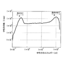
- FIG. 2 shows an example of the energy spectrum of the neutron beam emitted from the neutron source 3 described above.
- the horizontal axis represents neutron energy (kinetic energy)
- the vertical axis represents the number of neutrons passing through the unit cross section (cm 2 ) per unit time (second).
- neutrons having energy in the range A are thermal neutrons
- neutrons having energy in the range B are fast neutrons.
- the neutron beam incident on the inspection object 1 by the neutron source 3 reacts with the target component in the inspection object 1. Thereby, specific gamma rays derived from the target component are generated.
- specific gamma rays derived from the target component are generated.
- a plurality of types of specific gamma rays having different energies are generated from the target component.
- the gamma ray detection device 5 detects the intensities of a plurality of types of specific gamma rays generated by the incidence of neutron rays on the inspection object 1 as detection intensities.
- the gamma ray detection device 5 includes a gamma ray detector 5a and an intensity detector 5b.
- the gamma ray detector 5a detects gamma rays for each energy (each wavelength) of the gamma rays from the inspection object 1, and inputs the detected data to the intensity detector 5b.
- This detection data may be a peak value corresponding to the detected energy of each gamma ray.
- the intensity detector 5b obtains an energy spectrum of gamma rays based on each peak value input from the gamma ray detector 5a. This energy spectrum indicates the number of detections of gamma rays at each energy of gamma rays.
- the detected intensity of gamma rays may be a value proportional to the number of times of detection of gamma rays of the corresponding energy.
- the number of detections may be the number of detections over a predetermined measurement time.
- the predetermined measurement time is a time period from the time when the inspection object 1 is irradiated with the neutron beam to the origin, until a sufficient amount of gamma rays from the neutron beam is detected by the gamma ray detector 5a.
- the predetermined measurement time may be, for example, a time period such as 100 seconds, 200 seconds, or 300 seconds from the origin, but is not limited to these time periods.
- the gamma ray detection intensity may be a count rate R ⁇ described later.
- the gamma ray detector 5a may be, for example, a germanium detector, but is not limited thereto.
- the intensity detector 5b Based on the acquired energy spectrum, the intensity detector 5b obtains the intensities of a plurality of types of specific gamma rays (for example, in the energy spectrum) as detected intensities, and inputs these detected intensities to the ratio calculator 7.
- the intensity detection unit 5b includes the first specific gamma ray and the second specific gamma ray.
- the intensities may be obtained as detection intensities, and these detection intensities may be input to the depth detection unit 11 and the concentration evaluation unit 13.
- gamma rays having energy of 517 keV, 786 keV, 788 keV, 1165 keV, 1951 keV, and 6111 keV are main types of specific gamma rays derived from 35 Cl as the target component.
- the first specific gamma ray may be a gamma ray having an energy of 1951 keV
- the second specific gamma ray may be a gamma ray having an energy of 517 keV.
- the combination of the first specific gamma ray and the second specific gamma ray is not limited to this.
- the depth detection accuracy tends to be higher when the energy difference between the first specific gamma ray and the second specific gamma ray is larger.
- the detection intensity of specific gamma rays having high energy may not be used.
- the ratio calculation unit 7 obtains a ratio between detection intensities of a plurality of types of specific gamma rays input from the intensity detection unit 5b. In the embodiment, the ratio calculation unit 7 calculates the ratio of the detection intensity of the second specific gamma ray to the detection intensity of the first specific gamma ray.
- the depth data storage unit 9a stores depth data representing the relationship between the depth at which the target component exists in the inspection object 1 and the ratio of the detected intensities of a plurality of types of specific gamma rays. This depth data may be obtained in advance, and may be obtained by experiment, for example.
- a plurality of specimens made of the same material as the inspection object 1 are prepared.
- the depth at which the target component is present in the plurality of specimens differs among these specimens.
- the ratio between the detection intensities of a plurality of types of specific gamma rays is obtained using the neutron source 3 and the gamma ray detection device 5 described above.
- the depth data described above is created based on the depth of the target component in each of the plurality of specimens and the ratio of each of the plurality of specimens.
- the depth data created in this way is stored in advance in the depth data storage unit 9a.
- the depth data represents the relationship between the depth at which the target component exists in the inspection target 1 and the ratio of the second specific gamma ray to the first specific gamma ray.
- This condition is a neutron spectrum condition, a distance condition, and an orientation condition.
- the neutron spectrum condition is a condition that the energy spectrum of the neutron beam emitted from the neutron source 3 to the inspection object 1 (the specimen in the above experiment) is a set spectrum.
- the distance condition is a condition that the distance between the surface of the inspection object 1 (the specimen in the above experiment) and the detector 5a is a set distance.
- the orientation condition is the relationship between the orientation of the neutron beam emission port (in FIG. 1, the opening at the tip of the tubular shielding member 3f in FIG.
- the “same conditions” may further include other conditions (for example, measurement time conditions).
- This measurement time condition is a condition that the measurement time is the set time.
- the depth detection unit 11 obtains the depth at which the target component exists based on the depth data stored in the depth data storage unit 9a and the ratio calculated by the ratio calculation unit 7. At this time, the depth detection unit 11 may obtain the depth at which the target component exists by applying the ratio to the depth data. The depth detection unit 11 outputs the obtained depth.
- the output depth may be stored in an appropriate storage medium, displayed on a display, or printed on paper.
- the density data storage unit 9b stores density data representing the relationship between the detected intensity of the selected gamma ray and the density of the target component when either the first specific gamma ray or the second specific gamma ray described above is the selected gamma ray. .
- the density data storage unit 9b stores density data for each depth in the inspection object 1 in association with the depth. This concentration data may be obtained in advance, and may be obtained by experiment, for example.
- the following (1) to (3) are performed.
- a specimen (referred to as a known concentration specimen) that is formed of the same material as the inspection object 1 but has a known concentration of the target component.
- the zero concentration specimen is stacked on the known density specimen without any gap in the thickness direction of both.
- the zero-concentration specimen is a specimen that is formed of the same material as that of the inspection object 1 but whose concentration of the target component is zero.
- Each specimen has, for example, a rectangular parallelepiped shape.
- the neutron beam is emitted from the neutron source 3 so that the neutron beam passes through the zero-concentration specimen and the known-concentration specimen in this order. It is determined by the gamma ray detection device 5.
- the above (1) to (3) are performed for each of a plurality of known concentration specimens having different concentrations of the target component.
- the above-described concentration data is created based on the concentration of the target component in each of the plurality of known concentration specimens and the detected intensity of the selected gamma ray in each of the plurality of known concentration specimens.
- the detection intensity may be obtained by the following equation (A).
- Each symbol in formula (A) is the same as in formula (1) described later.
- Expression (A) is an expression when ⁇ ⁇ in Expression (1) described later is eliminated, that is, when ⁇ ⁇ is set to 1.
- R ⁇ ⁇ (A / t) / I ⁇ ⁇ / ( Ip / 50) (A)
- the distance from the surface where the neutron beam is incident on the zero concentration specimen to the known concentration specimen corresponds to the depth of the inspection object 1 (the depth from the surface 1a). Accordingly, the concentration data obtained as described above for one zero-concentration specimen (that is, the thickness of the specimen) is for one depth in the inspection object 1. Therefore, concentration data is obtained as described above for each of a plurality of zero concentration specimens having different thicknesses. Thereby, density data is obtained for each depth in the inspection object 1.
- a standard gamma ray source for example, 133 Ba or 152 Eu
- a detection efficiency ⁇ ⁇ (described later) is acquired in advance for each depth, and each depth is based on the detection efficiency of the depth. Concentration data may be obtained.
- the detected intensity of the selected gamma ray is obtained by the following equation (1). It should be noted that the density data regarding the depth (the thickness of the zero-concentration specimen) and the selected gamma ray (gamma ray energy) where the experiment was not performed may be obtained by interpolation based on the experimented density data and detection efficiency.
- the depth data storage unit 9a, the concentration data storage unit 9b, and the detection efficiency storage unit 8 described later may be different storage areas in the same storage device such as a semiconductor memory, a hard disk, or a USB memory as shown in FIG. However, it may be a separate storage device.
- the density evaluation unit 13 is based on the depth obtained by the depth detection unit 11, density data corresponding to the depth stored in the density data storage unit 9b, and the input detection intensity of the selected gamma ray. The concentration of the target component at the depth is obtained. At this time, the density evaluation unit 13 applies the detection intensity of the selected gamma ray to the density data corresponding to the depth obtained by the depth detection unit 11 among the density data corresponding to each depth in the density data storage unit 9b. By doing so, you may obtain
- Detection principle of target component depth ⁇ Gamma rays derived from elements> The principle of detecting the depth of the target component according to the first embodiment will be described in detail.
- various elements existing in the inspection object 1 cause a reaction of capturing neutrons to become a composite nucleus in an excited state.
- the composite nucleus immediately transitions from the excited state to the ground state, and at this time, gamma rays are emitted.
- the energy of gamma rays and the intensity of the gamma rays are derived from the element (nucleus) that emits the gamma rays.
- thermal neutrons are captured by the elements, but fast neutrons are not easily captured by the elements. Therefore, the thermal neutron incident on the inspection object 1 has a high probability of reacting with an object component existing in a range close to the surface 1 a in the inspection object 1.
- This range is, for example, a range from the surface 1a to several centimeters when the inspection object 1 is a concrete structure. Therefore, thermal neutrons are used for detection of target components in a range close to the surface 1a.
- the fast neutrons incident on the inspection object 1 hardly react with the target components in the inspection object 1 in the range close to the surface 1a, and are repeatedly scattered in the inspection object 1 to become thermal neutrons.
- fast neutrons become thermal neutrons and have a high probability of reacting with target components existing in a deep range from the surface 1a in the inspection object 1.
- This range is, for example, a range from 10 cm to 30 cm from the surface 1a when the inspection object 1 is a concrete structure. Therefore, thermal neutrons are used for detection of target components in a deep range from the surface 1a.
- Example> A plurality of mortar specimens made of mortar were prepared and tested.
- the concentration of chloride ions as the target component in these mortar specimens (hereinafter, referred to as salt concentration), respectively, 0.3kg / m 3, 0.5kg / m 3, 1kg / m 3, 3kg / m 3, It was 5 kg / m 3 .
- Each mortar specimen has a cubic shape and has a dimension of 40 mm on one side.
- each mortar specimen For each mortar specimen, a neutron beam was incident on the mortar specimen from the neutron source 3 and the energy spectrum of gamma rays generated in the mortar specimen was measured. Each mortar specimen was tested under the same conditions. That is, the conditions include the above-described neutron spectrum conditions, distance conditions, and orientation conditions.
- FIG. 3 shows the relationship between the count rate R ⁇ (times / second), which is the intensity of the specific gamma ray detected by the gamma ray detector 5a in the experiment, and the salinity concentration.
- R ⁇ times / second
- FIG. 3 the measurement result of the specific gamma ray whose energy is 517 keV, 786 keV, 788 keV, 1165 keV, and 1951 keV is shown.
- 786KeV and 788keV so close value, in FIG. 3, to the combined detection intensity of gamma rays of these two energy as one energy 787KeV, it has a counting rate R gamma specific gamma ray.
- A indicates the number of times of detection of specific gamma rays for each energy.
- is epsilon gamma shows a gamma-ray detection efficiency (% / 100), is a value obtained in advance by using a standard gamma ray source.
- the gamma ray detection efficiency is the ratio of the number of gamma rays detected by the gamma ray detector 5a to the amount of gamma rays from the gamma ray source (where the gamma rays are emitted), and is inversely proportional to the energy of the gamma rays. It is a value that is inversely proportional to the distance.
- the gamma ray detection apparatus 5 assumes that the distance between the gamma ray source in the inspection object 1 and the gamma ray detector 5a is a predetermined constant value, and ⁇ for each energy. ⁇ is set (hereinafter, ⁇ ⁇ is also expressed as ⁇ ⁇ S and ⁇ ⁇ d . The same applies to the second embodiment and the third embodiment), and the gamma ray detection device 5 is provided for each type of specific gamma ray. Based on the corresponding ⁇ ⁇ , an integrated value of the count rate R ⁇ over the measurement time is obtained as the detected intensity of the specific gamma ray of the type.
- the gamma ray detection efficiency (that is, the gamma ray detection efficiency used in step S2 described later) related to obtaining the ratio between the detection intensities of a plurality of types of specific gamma rays is the air between the gamma ray source and the gamma ray detector 5a.
- the values are in the state where nothing exists except for.
- the gamma ray detection efficiency relating to obtaining the concentration of the target component is a value corresponding to the material of the inspection object 1 and the specimen. There should be.
- I p is the average current ( ⁇ A) of the proton beam incident on the target 3d at the time of measurement, and 50 indicates that the count rate R ⁇ is normalized at 50 ⁇ A. This numerical value may not be 50 but may be 10 or 100.
- the count rate R ⁇ indicates the intensity of gamma rays.
- the count rate R ⁇ is higher for each salinity concentration as the energy of the specific gamma ray is higher.
- the transmittance means the proportion of gamma rays that can pass through the surface of the mortar specimen or inspection object 1 among the gamma rays generated in the mortar specimen or inspection object 1. That is, in the mortar specimen or inspection object 1, when a predetermined amount of gamma rays pass through the surface out of the total amount of gamma rays generated at a predetermined depth from the surface, the ratio of the predetermined amount to the total amount is the transmittance. Yes (hereinafter the same).
- the detection intensity of each specific gamma ray increases as the salt concentration in the mortar specimen increases.
- the salinity concentration and the detection intensity of the specific gamma ray are in a substantially proportional relationship. Therefore, it can be said that the intensity ratio between a plurality of types of specific gamma rays does not depend on the concentration of the target component (salt).
- the depth of the target component can be obtained as described later by using the difference in transmittance of the plurality of types of specific gamma rays and the difference in the intensity ratio of the types of specific gamma rays.
- FIG. 3 shows that the salinity concentration can be evaluated even when the salinity concentration is as low as 0.3 kg / m 3 . Therefore, since the lower limit value of the salt concentration that causes corrosion of the reinforcing bars in the concrete is about 1.2 to 2.5 kg / m 3 , the concentration evaluation unit 13 determines whether or not there is a concentration of salt that causes corrosion of the reinforcing bars. It can be detected.
- FIG. 4 shows the theoretical calculated values of the transmittance of multiple types of gamma rays for concrete as a ratio.
- the horizontal axis indicates the energy of gamma rays
- the vertical axis indicates the transmittance indicating the proportion of gamma rays that pass through the surface of the gamma rays generated in the concrete. That is, assuming that the transmittance of gamma rays with energy of 2000 keV is 1, the ratio of the transmittance of each gamma ray to this transmittance is shown.
- the energy of each gamma ray is 500 keV and 1250 keV.
- circles are calculated values for gamma rays generated at a depth of 1 cm from the concrete surface, and square marks are calculated values for gamma rays generated at a depth of 5 cm from the concrete surface.
- triangles are calculated values for gamma rays generated at a depth of 10 cm from the concrete surface. As can be seen from FIG. 4, for each depth, the higher the gamma ray energy, the higher the transmittance.
- FIG. 5 is a schematic diagram for explaining the principle of the depth detection of the target component according to the first embodiment.
- FIG. 5 shows a case where specific gamma rays are generated by causing neutrons to react with salt in the concrete by causing neutrons to enter the surface of the concrete as the inspection object 1.
- the ratio between the detected intensities of a plurality of types of specific gamma rays that have passed through the surface is determined. For example, the ratio (A1 ⁇ P1) / (A3 ⁇ P3) of the detection intensity A1 ⁇ P1 to the detection intensity A3 ⁇ P3 is obtained.
- This ratio does not depend on the salinity concentration of the first depth.
- Both A1 and A3 are proportional to the salinity concentration at the first depth, and as a result, in A1 / A3, variations in A1 and A3 due to the salinity concentration cancel each other.
- A1 / A3 does not depend on the first depth.
- the intensity of a neutron beam (thermal neutron) reaching a certain depth is proportional to the depth, and the intensity of gamma rays generated at that depth is the neutron beam reaching the depth (thermal neutron) ), And as a result, in A1 / A3, variations in A1 and A3 due to depth cancel each other. Therefore, in the ratio (A1 ⁇ P1) / (A3 ⁇ P3), A1 / A3 does not change depending on the salinity concentration and the existence depth, and is a value derived from the target component. On the other hand, the transmittances P1 and P3 are not proportional to the first depth, but are values corresponding to the first depth. Therefore, the intensity ratio (A1 ⁇ P1) / (A3 ⁇ P3) is a value corresponding to the first depth.
- the ratio (B1 ⁇ Q1) / (B3 ⁇ Q3) of the detected intensity is a value corresponding to the second depth.
- the detection intensity ratio (C1 ⁇ R1) / (C3 ⁇ R3) is a value corresponding to the third depth.
- the above-mentioned depth data representing the relationship between such a ratio and the depth at which the target component (in this case, salinity) exists is obtained in advance, and based on the ratio of the detected intensity measured during the inspection and the depth data.
- the depth at which the target component exists can be obtained.
- the depth obtained by the depth detection unit 11 described above is a rough value (for example, average depth) of the depth at which salinity exists. Become. Even in this case, it is possible to know a rough value of the depth at which salinity exists from the depth output by the depth detection unit 11. For example, when the depth output from the depth detection unit 11 is close to the position of the reinforcing bar in the concrete structure as the inspection object 1, it can be determined that the reinforcing bar may be corroded by salt. Moreover, about the same test object 1, the secular change of the penetration depth of the salinity in the test object 1 is known by calculating
- prescribed test day interval for example, every month or every year.
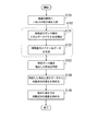
- FIG. 6 is a flowchart showing the nondestructive inspection method according to the first embodiment. This method may be performed using the nondestructive inspection apparatus 10 described above. This method has steps S1 to S5.
- step S1 the surface 1a of the inspection object 1 is irradiated with a neutron beam from the neutron source 3. Thereby, the neutron beam incident on the inspection object 1 reacts with the target component in the inspection object 1, and a plurality of types of specific gamma rays derived from the target component are generated.
- step S2 the gamma ray detection device 5 detects the intensities of a plurality of types of specific gamma rays generated in step S1 as detection intensities.
- Step S2 has steps S21 and S22.
- step S21 gamma rays of each energy are detected by the gamma ray detector 5a.
- step S22 the intensity detector 5b obtains an energy spectrum of gamma rays based on the detection data obtained in step S21 (the peak value corresponding to the detected energy of each gamma ray), and based on this energy spectrum, According to the equation (1), the intensities of a plurality of types of specific gamma rays are respectively detected as detection intensities.
- the gamma-ray detection efficiency epsilon gamma used in step S2 is above the epsilon gammaS.
- step S3 an index value indicating the depth at which the target component exists is generated based on the detection result in step S2. That is, the ratio calculation unit 7 obtains the ratio between the detected intensities of a plurality of types of specific gamma rays detected in step S2 as an index value. In the embodiment, this ratio is a ratio of the detection intensity of the second specific gamma ray to the detection intensity of the first specific gamma ray.
- step S4 based on the ratio obtained in step S3 and the depth data in the depth data storage unit 9a, the depth detection unit 11 obtains the depth at which the target component exists.
- step S5 based on the depth obtained in step S4, the density data for the depth stored in the density data storage unit 9b, and the detected intensity of the selected gamma ray, the density evaluation unit 13 determines the depth. Obtain the concentration of the target component at.
- step S5 is performed as follows. Based on the depth obtained in step S4, the density data for the depth stored in the density data storage unit 9b, and the detected intensity of the selected gamma ray, the density evaluation unit 13 determines the target component at the depth. Determine the concentration of. In this case, the gamma ray detection device 5 (intensity detection unit 5b) obtains the number of detection times A of the selected gamma rays based on the energy spectrum of the gamma rays acquired in step S2, and the number of detection times A and the above equation (A) are obtained.
- the detected intensity of the selected gamma ray is obtained, and this detected intensity is input to the density evaluating unit 13 and used in the density evaluating unit 13 in step S5.
- the detection intensity of the selected gamma ray used at this time may be one newly selected and acquired from the energy spectrum of the gamma ray acquired in step S2.
- step S5 is performed as follows. First, the gamma ray detection efficiency epsilon gamma used in the step S2 and epsilon gammaS, a gamma ray detection efficiency epsilon gamma corresponding to the depth determined in step S4 as epsilon .gamma.d, intensity detection unit 5b, replace epsilon gammaS the epsilon .gamma.d On the basis of the above-described equation (1) and the number of detection times A of the selected gamma ray (for example, acquired by the intensity detection unit 5b based on the energy spectrum of the gamma ray obtained in step S2 or newly selected and acquired).
- the detection intensity of the selected gamma ray is obtained.
- the gamma ray detection efficiency ⁇ ⁇ corresponding to each depth in the inspection object 1 that is, the gamma ray detection efficiency ⁇ ⁇ corresponding to each depth used to acquire density data for each depth). 1 is stored in the detection efficiency storage unit 8 as shown in FIG. 1, and the intensity detection unit 5b detects the detection efficiency data in the detection efficiency storage unit 8 and the depth (depth detection obtained in step S4).
- the density evaluating unit 13 is based on the detected intensity obtained by the intensity detecting unit 5b, the depth obtained in step S4, and the density data regarding the depth stored in the density data storage unit 9b. The concentration of the target component at the depth is obtained.
- the intensities of a plurality of types of specific gamma rays generated by the reaction between the neutron incident on the inspection object 1 and the target component are detected.
- the ratio between the detected intensities of a plurality of types of specific gamma rays is a value corresponding to the depth at which the target component exists. That is, this ratio indicates the depth at which the target component exists. Therefore, by obtaining such a ratio, it is possible to detect the depth at which the target component exists. Therefore, the depth of the target component in the inspection object 1 can be detected nondestructively. For example, it is possible to detect the depth of the position of the target component existing in the test target 1 and evaluate the concentration of the target component at the depth without collecting the core from the concrete structure that is the test target 1.
- the gamma ray detection efficiency at the depth in the concrete where the target component exists ( ⁇ ⁇ in the calculation formula (1) of the counting rate R ⁇ described above) (that is, the concentration data As described above with respect to acquisition, it is possible to derive how much salinity is present in the depth of the position of the target component obtained previously by acquiring detection efficiency data in advance).
- the salt concentration 1 kg / m 3 at which the corrosion of steel inside the concrete shown in the concrete standard specification starts is set as a lower limit, or a concentration lower than 1 kg / m 3 is set as a lower limit, and a high concentration assumed from the lower limit (
- concentration data for example, by obtaining the above-mentioned concentration data for a range up to 10 kg / m 3 (that is, by drawing a calibration curve), the comparison between the data obtained at the actual measurement and the calibration curve (concentration data) can be performed. By doing so, the concentration evaluation can be performed.
- the salt concentration at which corrosion of the steel inside the concrete begins depends on the cement type and the water-concrete ratio, and is in the range of 1.2 to 2.5 kg / m 3 .
- the neutron source 3 may be configured such that the angle formed between the direction in which the proton beam is incident on the target 3d and the direction of the emission port of the neutron beam in the neutron source 3 is 90 degrees.
- the neutron source 3 having this configuration irradiates the inspection object 1 with a neutron beam mainly composed of thermal neutrons, with the fast neutron component of the thermal neutrons and fast neutrons greatly reduced. Thereby, the depth of the target component within a range close to the surface 1a of the inspection object 1 can be obtained with high accuracy.
- a thermal neutron shielding material is installed on the surface 1a of the inspection object 1 even when the speed reduction portion 3g described later is not provided, or even in a configuration provided with the speed reduction portion 3g.
- the neutron source 3 can irradiate the inspection object 1 substantially with only fast neutrons among thermal neutrons and fast neutrons. Thereby, the depth of the target component within a deep range from the surface 1a of the inspection object 1 can be obtained with high accuracy.
- FIG. 7 shows a configuration of a nondestructive inspection apparatus 30 according to the second embodiment of the present invention.
- the configuration of the nondestructive inspection apparatus 30 according to the second embodiment is different from the configuration of the nondestructive inspection apparatus 10 according to the first embodiment in the points described below.
- the second embodiment may not be described below in the same manner as in the first embodiment.
- the inspection object 1 is a concrete structure and the target component is salt, but the inspection target 1 and the target component are not limited to this combination.
- the nondestructive inspection apparatus 20 includes a neutron source 3, a gamma ray detection apparatus 5, a time point specifying unit 15, a depth data storage unit 9c, a depth detection unit 19, a concentration data storage unit 9b, A density evaluation unit 14 is provided.
- the neutron source 3 emits a pulsed neutron beam.
- the pulse width of the proton beam for pulsed neutron emission is, for example, about 0.1 millisecond or smaller than 0.1 millisecond, but this does not interfere with the detection of the depth of the target component. It is not limited to.
- the repetition frequency of the proton beam pulse is, for example, about 100 Hz, but is not limited to this as long as the detection of the depth of the target component is not hindered.
- FIG. 8A is a schematic diagram for explaining the pulse time width of the proton beam and the repetition period (reciprocal of the repetition frequency) in the neutron source 3.
- the horizontal axis indicates time
- the vertical axis indicates the magnitude of the proton beam pulse signal (the synchronization signal described above)
- the repetition period is equal to the repetition period of the proton beam described above.
- This pulse neutron beam is emitted under distance conditions.
- the distance condition is a condition that the distance between the surface 1a of the inspection object 1 (a specimen when depth data described later is obtained) and the emission position of the pulsed neutron beam in the neutron source 3 is set as a set distance.
- This discharge position may be, for example, the surface of the target 3d on the inspection object 1 side.
- release position may be the surface by the side of the test object 1 in the deceleration part 3g.
- the neutron source 3 further includes a speed reducing unit 3g through which neutrons generated in the target 3d pass.
- the speed reducer 3g is formed of a material (for example, polyethylene) that slows the passing fast neutrons and converts them into thermal neutrons. Therefore, some of the neutrons generated in the target 3d pass through the speed reduction unit 3g, and part of them become thermal neutrons and enter the inspection object 1. Therefore, the neutron source 3 inspects thermal neutrons and fast neutrons. The light can enter the object 1.
- the pulsed neutron beam incident on the inspection object 1 by the neutron source 3 reacts with the target component in the inspection object 1. Thereby, gamma rays (specific gamma rays) derived from the target component are generated.
- the gamma ray detection device 5 detects specific gamma rays generated by pulsed neutron rays incident on the inspection object 1. More specifically, the gamma ray detection device 5 detects the energy spectrum of gamma rays at each time point after the time point when the neutron source 3 makes the pulse proton beam incident on the target 3d (that is, the neutron generation time point as the reference time point), Time difference versus spectral data is generated by associating each time point with respect to the reference time point (that is, time difference from the reference time point) and the energy spectrum of the gamma ray detected at the time point.
- the gamma ray detection apparatus 5 includes a gamma ray detector 5a, a data acquisition unit 5c, and an intensity detection unit 5b.
- the gamma ray detector 5a detects the intensity of the gamma ray for each energy (each wavelength) of the gamma ray from the inspection object 1 at each time point. That is, the gamma ray detector 5a detects the energy spectrum of gamma rays at each time point, and outputs the energy spectrum to the data acquisition unit 5c at each time point.
- the data acquisition unit 5c generates the above-described time difference versus spectrum data representing the energy spectrum at each time point based on the energy spectrum input from the gamma ray detector 5a at each time point.
- the energy spectrum at each time point indicates the number of detection times of gamma rays at each energy of the gamma rays detected at that time point.
- each time point when the energy spectrum is detected means a time difference between the neutron generation time point (reference time point) and the gamma ray detection time point.
- the gamma ray detection time point may be a time point when the gamma ray detector 5a detects each gamma ray corresponding to the energy spectrum.
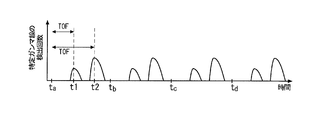
- FIG. 9 shows an outline of an embodiment of time difference versus spectral data generated by the data acquisition unit 5c.
- the horizontal axis represents TOF (Time of Flight), which is the time difference between the time of neutron generation and the time of gamma ray detection
- the vertical axis represents the energy of the detected gamma rays.
- A indicates a region where the number of times the corresponding energy gamma ray is detected at the corresponding time point is approximately 1 ⁇ 10 3 or more
- B indicates that the corresponding energy gamma ray is detected at the corresponding time point.
- the data acquisition unit 5c receives a synchronization signal indicating the proton beam incident time (neutron generation time) from the neutron source 3, and generates the above time difference versus spectral data based on this synchronization signal. For example, the data acquisition unit 5c measures the time with the time when the synchronization signal is received as the time origin, and associates each time with respect to the origin and the energy spectrum detected by the gamma ray detector 5a at the time. Generate time difference versus spectral data.
- the intensity detection unit 5b obtains the detection intensity of the specific gamma ray based on the time difference versus spectrum data acquired / generated by the data acquisition unit 5c.
- the specific gamma ray is a selected gamma ray related to density data to be described later, and the detection intensity is a value proportional to the number of detection times of the specific gamma ray over the predetermined measurement time described in the first embodiment.
- the time point specifying unit 15 specifies the time point when the specific gamma ray is detected based on the time difference versus spectrum data acquired / generated by the gamma ray detection device 5 (data acquisition unit 5c). For example, the time point specifying unit 15 specifies the time point when the energy of the specific gamma ray is detected from the energy spectrum of each time point detected by the gamma ray detector 5a based on the time difference versus spectrum data.
- the time point specifying unit 15 extracts data indicating the number of times the specific gamma ray is detected at each time point from the time difference versus spectrum data, and based on the extracted data, the time point when the specific gamma ray is detected (that is, the specific gamma ray is detected). Time) is specified as the time when the energy of the specific gamma ray is detected.
- the time point specifying unit 15 specifies a specific type of specific gamma rays (hereinafter also referred to as specified gamma rays). It is better to specify the point in time when is detected.
- the depth data storage unit 9c detects the depth at which the target component exists in the inspection target 1, and specific gamma rays (designated gamma rays) derived from the target component when a pulsed neutron beam is incident on the inspection target 1.
- Depth data representing a relationship with a specific time point is stored. This depth data may be obtained by experiment, for example.
- a plurality of specimens made of the same material as the inspection object 1 are prepared.
- the depth at which the target component is present in the plurality of specimens differs among these specimens.
- a pulsed neutron beam is made incident on the surface of the specimen by the neutron source 3 described above, and the energy of a specific gamma ray (designated gamma ray) in the gamma ray energy spectrum at each time point detected by the gamma ray detector 5a.
- the detection time point is specified by the time point specifying unit 15.
- the depth of the target component in one specimen and the detection time point (specific time point) specified for the specimen are set as one set of data. Create depth data.
- the depth data created in this way is stored in advance in the depth data storage unit 9c.
- the above-described experiment for obtaining the depth data and the actual inspection of the inspection object 1 are performed under the above-described distance condition. Further, the above-described experiment for obtaining the depth data and the actual inspection of the inspection object 1 (step S101 described later) are preferably performed under the above-described neutron spectrum conditions and orientation conditions.
- the depth detection unit 19 obtains the depth at which the target component exists based on the depth data stored in the depth data storage unit 9c and the time point specified by the time point specifying unit 15. At this time, the depth detection unit 19 may obtain the depth at which the target component exists by applying the time point to the depth data. The depth detection unit 19 outputs the obtained depth. The output depth may be input to the density evaluation unit 14, stored in an appropriate storage medium, displayed on a display, or printed on paper.
- the depth data for the fast neutron and the thermal neutron is determined in advance as described above.
- the horizontal axis indicates time
- the vertical axis indicates the number of detection times of a specific gamma ray.
- the time t a, t b, t c , t d of FIG. 8B respectively, the time t a of Figure 8A, t b, t c, corresponding to t d.
- the specific gamma ray detection time point (specification) in the extracted data for example, the data in FIG. 8B
- the distance between the emission position of the neutron source 3 and the surface 1a of the inspection object 1 and the pulse width and repetition frequency of the proton beam are set in advance by simulation or experiment so that they can be distinguished from each other.
- the gamma rays by the irradiated fast neutrons are detected at an early time point, and the gamma rays by the irradiated thermal neutrons are detected at a later time point.
- the pulse width of the proton beam in FIG. 8A is large, the waveform width (time width) of the number of detections in FIG. 8B is widened, and the distance between the emission position of the neutron source 3 and the surface 1a of the inspection object 1 is short. 8B, the time point t1 and the time point t2 are close to each other. Considering this, the distance, pulse width, and repetition frequency are set in advance.
- the specific time point is a specific time point within a time range in which the number of times of detection of the specific gamma ray occurs.
- the specific time point may be a time point when the number of times of detection reaches a peak, It may be a start time at which the start of occurrence occurs.
- the depth detector 19 When obtaining both the depth data for fast neutrons and the depth data for thermal neutrons, for example, the depth detector 19 extracts data indicating the number of times of detection of a specific gamma ray at each time point from the above time difference versus spectrum data.
- the two specific time points of the number of detections for example, t1 and t2 in FIG. 8B
- the depth at which the target component exists may be obtained based on the later specific time (t2) of the two specific time points and the depth data for thermal neutrons.
- the neutron source 3 is configured to irradiate the inspection object 1 with thermal neutrons and fast neutrons. In this case, it is possible to detect a target component existing in a range close to and deep from the surface 1a in the inspection target 1.
- the neutron source 3 Of the fast neutrons substantially only fast neutrons are irradiated onto the inspection object 1. In this case, the depth of the target component existing in a deep range from the surface 1a in the inspection object 1 can be detected. In this case, it is not necessary to obtain the depth data for thermal neutrons.
- the concentration data storage unit 9b in the second embodiment is the same as the concentration data storage unit 9b in the first embodiment. That is, the density data storage unit 9b stores density data representing the relationship between the detected intensity of the selected gamma ray and the density of the target component.
- the selected gamma ray may be the above-mentioned designated gamma ray, or may be another type of specific gamma ray.
- the density evaluation unit 14 is based on the depth obtained by the depth detection unit 19, the density data corresponding to the depth stored in the density data storage unit 9b, and the input detection intensity of the selected gamma ray. The concentration of the target component at the depth is obtained.
- the density evaluation unit 14 outputs the obtained density.
- the output density may be stored in an appropriate storage medium, displayed on a display, or printed on paper.
- FIG. 10 is a flowchart showing a nondestructive inspection method according to the second embodiment. This method may be performed using the nondestructive inspection apparatus 20 described above. This method includes steps S101 to S105.
- step S101 the neutron source 3 irradiates the surface 1a of the inspection object 1 with a pulsed neutron beam.
- the pulsed neutron beam incident on the inspection object 1 reacts with the target component in the inspection object 1 to generate specific gamma rays derived from the target component.
- step S102 a specific gamma ray derived from the target component in the inspection object is detected from the gamma rays generated in step S101, and the time point when the specific gamma ray (designated gamma ray) is detected is specified.
- step S102 may include steps S121 and S122.
- step S121 the gamma ray detector 5a detects the gamma ray energy spectrum at each time point.
- step S122 while measuring the time from the time when the above-mentioned synchronization signal is received as the origin, time difference pair spectrum data in which the energy spectrum detected by the gamma ray detector 5a at each measured time is associated with the time is generated. To do.
- step S103 based on the detection result in step S102, the time point specifying unit 15 specifies the time point when the specific gamma ray (designated gamma ray) is detected after the time point when the pulse neutron beam is irradiated in step S101.
- the time point identifying unit 15 may identify the time point when the specific gamma ray is detected.
- step S104 the depth at which the target component exists is obtained by the depth detection unit 19 based on the time point specified in step S103 and the depth data in the depth data storage unit 9c.
- step S105 based on the depth obtained in step S104, the density data regarding the depth stored in the density data storage unit 9b, and the detected intensity of the selected gamma ray, the density evaluation unit 14 determines the depth. Obtain the concentration of the target component at.
- step 105 is performed as follows. First, based on the number of detection times A of the selected gamma ray and the above formula (A), the intensity detector 5b obtains the detected intensity of the selected gamma ray. The number of detections A used at this time is based on the detection result of the selected gamma ray acquired for the inspection object 1 by the neutron source 3 and the gamma ray detection device 5 (for example, newly selected in step S102 or step S102). It is.
- the density evaluation unit 14 is based on the detection intensity of the selected gamma ray obtained by the intensity detection unit 5b, the depth obtained in step S104, and the density data regarding the depth stored in the density data storage unit 9b. Thus, the concentration of the target component at the depth is obtained.
- step S105 is performed as follows. First, with the gamma ray detection efficiency ⁇ ⁇ corresponding to the depth obtained in step S104 as ⁇ ⁇ d , the intensity detection unit 5b determines the selected gamma ray based on the above equation (1) and the number of detections A of the selected gamma ray. Find the detection intensity.
- the number of detections A used at this time is based on the detection result of the selected gamma ray acquired for the inspection object 1 by the neutron source 3 and the gamma ray detection device 5 (for example, newly selected in step S102 or step S102). It is.
- the same detection efficiency data as in the first embodiment is stored in the detection efficiency storage unit 8 as shown in FIG. 7, and the intensity detection unit 5b obtains the detection efficiency data in the detection efficiency storage unit 8 and in step S104.
- the above-mentioned ⁇ ⁇ d is specified, and the above formula (1) is used as described above.
- the concentration evaluation unit 14 detects the selected gamma ray detection intensity obtained by the intensity detection unit 5b, the depth obtained in step S104 (the depth input from the depth detection unit 19), and the concentration data storage unit 9b.
- the concentration of the target component at the depth is obtained based on the concentration data for the depth stored in the table.
- the specific gamma ray generated by the reaction between the neutron incident on the inspection object 1 and the target component is detected, and the point in time when the specific gamma ray is detected is specified.
- the identified time point indicates the depth at which the target component exists. Therefore, the depth at which the target component exists can be detected by obtaining such a time point. Therefore, the depth of the target component in the inspection object 1 can be detected nondestructively. For example, it is possible to detect the depth of the position of the target component existing in the test target 1 and evaluate the concentration of the target component at the depth without collecting the core from the concrete structure that is the test target 1. .
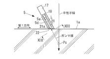
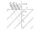
- FIG. 11A is a diagram for explaining the detection principle according to the third embodiment.
- the gamma ray detection device 5 collimates gamma rays to be detected. That is, the gamma ray detection device 5 detects gamma rays that have flew in a direction within a specific range among gamma rays generated at a specific depth in the inspection object 1.
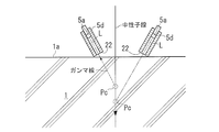
- a neutron beam with a reduced cross-sectional dimension is incident on the inspection object 1, and a position Pc where the reference straight line L of the gamma ray detector 5a and the straight path of the neutron beam intersect (hereinafter also simply referred to as an intersection position Pc).
- a position Pc where the reference straight line L of the gamma ray detector 5a and the straight path of the neutron beam intersect (hereinafter also simply referred to as an intersection position Pc).
- Gamma rays that have been flying along the reference straight line L are selectively incident on the gamma ray detector 5a, and gamma rays flying in other directions are incident on the gamma ray detector 5a. This is blocked by a later-described gamma ray shielding portion 5d.
- intersection position Pc depth
- the intersection position Pc changes by changing the geometric relationship (relationship between position and orientation) between the reference straight line L and the neutron beam path, it is checked whether the target component exists at each intersection position Pc. it can.
- the neutron beam is incident on the inspection object 1 with the cross-sectional dimension of the neutron beam being reduced to the upper limit value or less.
- the upper limit value may be several tens of millimeters or less, for example, 50 millimeters or less or 30 millimeters or less.
- the degree of narrowing the neutron beam may be set in the neutron source 3 according to the required resolution of the crossing position Pc.
- the cross section of the neutron beam is large, the number of times of detection of gamma rays increases, but the resolution of the intersection position Pc decreases. If the cross section of the neutron beam is small, the number of detections of gamma rays decreases, but the resolution of the intersection position Pc increases.
- the cross-sectional shape of the neutron beam may be, for example, a circle or a shape close to a circle, but is not limited thereto, and may be an ellipse or a rectangle.
- the degree of collimating gamma rays (the area of the opening 21a of the gamma ray shielding portion 5d described later) is set according to how much gamma rays are detected from the region (intersection position Pc). If the area of the opening 21a is large, the number of times of detection of gamma rays increases, but the resolution of the intersection position Pc decreases. If the area of the opening 21a is small, the number of detections of gamma rays decreases, but the resolution of the intersection position Pc increases.
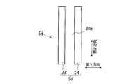
- FIG. 11B is a partially enlarged view of FIG. 11A and shows an example of the shape of the gamma ray detector 5a and the gamma ray shielding unit 5d.
- the gamma ray detector 5a has a detection surface 5a1, and detects gamma rays incident on the detection surface 5a1.
- the area D1 of the detection surface 5a1 is larger than the cross-sectional area D2 of the gamma ray passage hole 21 in the gamma ray shielding portion 5d and larger than the area D3 of the opening 21a. That is, when viewed from the direction of the center line L of the gamma ray passage hole 21, for example, as shown in FIG. 11B, the gamma ray passage hole 21 and the opening 21a are smaller than the detection surface 5a1 and the gamma ray detector 5a and gamma ray.
- a shielding part 5d may be formed.
- FIG. 12 shows a configuration of a nondestructive inspection apparatus 30 according to the third embodiment of the present invention.
- the nondestructive inspection device 30 includes the neutron source 3 and the gamma ray detection device 5 described in the first embodiment or the second embodiment.
- the gamma ray detection apparatus 5 has a configuration described below.
- the gamma ray detection device 5 that is not described below may be the same as in the case of the first embodiment or the second embodiment described above.
- the gamma ray detection device 5 includes a gamma ray detector 5a, an intensity detection unit 5b, and a gamma ray shielding unit 5d.
- the gamma ray detector 5a detects gamma rays for each energy of the gamma rays generated in the inspection object 1 by the incidence of neutron rays, and inputs the detected data to the intensity detector 5b.
- This detection data may be a peak value corresponding to the detected energy of each gamma ray.
- the gamma ray detector 5a may be, for example, a germanium detector, but is not limited thereto.
- the intensity detector 5b obtains an energy spectrum of gamma rays based on each peak value input from the gamma ray detector 5a.
- the intensity detector 5b obtains the intensity of the specific gamma ray as the detected intensity based on this energy spectrum.
- the intensity detector 5b uses the intensity of the specific gamma rays of the type specified in advance as the detection intensity. Ask.
- the intensity detector 5b outputs the obtained detected intensity of the specific gamma ray.
- the output detected intensity may be displayed on a display.
- the gamma ray shielding portion 5d is made of a material having a high shielding ability against gamma rays (for example, lead, tungsten, tantalum, or iron) so as not to substantially pass gamma rays.
- the gamma ray shielding portion 5 d forms a gamma ray passage hole 21.
- the gamma ray passage hole 21 has an opening 21a through which gamma rays can enter.
- a gamma ray detector 5a is arranged at a position shifted from the opening 21a to the back side in the gamma ray passage hole 21.
- the opening 21a and the gamma ray detector 5a are located on the reference straight line L.
- the gamma ray detector 5a substantially detects only gamma rays that have entered from the opening 21a along the reference straight line L.
- the reference straight line L may be the center line of the gamma ray passage hole 21.
- a cooling device 17 (not shown in FIG. 12 but shown in FIGS. 11A and 11B) for cooling the germanium detector 5a is provided.
- the cooling device 17 may be provided outside the gamma ray shielding unit 5d. In this case, the cooling device 17 may cool the germanium detector 5a through the hole 18 provided on the opposite side of the opening 21a in the gamma ray shielding portion 5d.
- the gamma ray shielding part 5d has a front end face 22 in which an opening 21a is formed.
- the reference straight line L may extend obliquely with respect to the distal end surface 22. That is, the tip surface 22 is formed such that the reference straight line L extends obliquely with respect to the tip surface 22.
- 13A and 13B show specific examples of the shape of the gamma ray shielding portion 5d.
- 13A and 13B are both XIII-XIII arrow views of FIG. 11A, but show different specific examples.
- the gamma ray shielding portion 5d is formed so as to surround the entire circumference of the gamma ray passage hole 21.
- the cross-sectional shape of the gamma ray passage hole 21 may be a circle as shown in FIG. 13A or another shape.
- the gamma ray shielding portion 5 d has two shielding blocks 23 and 24 that are formed of the above-described material and that are spaced apart from each other so as not to substantially pass gamma rays. is there.
- the gap 21 extends along the reference straight line L.
- the dimension of the gap 21 in the first direction orthogonal to the reference straight line L is smaller than the dimension of the gap 21 in the second direction orthogonal to both the reference straight line L and the first direction.
- the size of the gap 21 in the first direction is 1/2 or less, 1/3 or less, or 1/5 or less of the size of the gap 21 in the second direction.
- the dimension of the cross section of the neutron beam is set to the above upper limit value or less in at least the first direction out of the first direction and the second direction.
- the gamma ray detector 5a, the intensity detection unit 5b, and the gamma ray shielding unit 5d corresponding to each other may be one set, and the gamma ray detection device 5 may include one set or a plurality of sets. In FIG. 12, two sets are illustrated. Note that the gamma ray shielding unit 5d corresponding to each gamma ray detector 5a in FIG. 12 may have the shape described based on FIG. 13A or 13B.
- the concentration data storage unit 9b in the third embodiment is the same as the concentration data storage unit 9b in the first embodiment. That is, the density data storage unit 9b stores density data representing the relationship between the detected intensity of the selected gamma ray and the density of the target component.
- the density evaluation unit 16 determines the depth based on the depth obtained as described later, the density data corresponding to the depth stored in the density data storage unit 9b, and the input detection intensity of the selected gamma ray. The concentration of the target component is calculated. The density evaluation unit 16 outputs the obtained density.
- the output density may be stored in an appropriate storage medium, displayed on a display, or printed on paper.
- FIG. 14 is a flowchart showing a nondestructive inspection method according to the third embodiment. This method may be performed using the nondestructive inspection apparatus 30 described above. This method includes steps S201 to S205.
- step S201 the neutron source 3 and the gamma ray detection device 5 are arranged so that the path of the neutron beam emitted from the neutron source 3 and the extended line of the reference line L of the gamma ray shielding portion 5d intersect inside the inspection object 1. Place.
- the gamma ray shielding portion 5d and the gamma ray are arranged so that the tip surface 22 of the gamma ray shielding portion 5d faces the surface 1a of the inspection object 1 (for example, the flat tip surface 22 is parallel to the flat surface 1a). You may arrange
- the tip surface 22 may be further brought into contact with the surface 1a, or a slight gap may be placed between the tip surface 22 and the surface 1a.
- the incident neutron beam and the surface 1a of the inspection object 1 do not have to be perpendicular, and the neutron beam may be incident obliquely.
- the arrangement of the gamma ray detector 5a may be changed depending on the angle between the incident neutron beam and the surface 1.
- Step S202 is performed in the arrangement state performed in step S201.
- a neutron beam is incident on the surface 1a of the inspection object 1 by the neutron source 3.
- the gamma ray detector 5a detects gamma rays of each energy generated by the incidence of neutron rays, and inputs the detection data to the intensity detector 5b.
- the neutron beam incident on the surface 1a in step S202 may be a pulsed neutron beam or a temporally continuous neutron beam as in the second embodiment.
- step S203 the intensity detector 5b obtains an energy spectrum of gamma rays based on the detection data obtained in step S202 (the peak value corresponding to the detected energy of each gamma ray), and specifies the energy spectrum based on the energy spectrum.
- the intensity of the gamma ray (that is, the selected gamma ray) is obtained as the detected intensity (for example, according to equation (A)).
- the detected intensity is output from the intensity detector 5b.
- step S204 based on the detected intensity of the specific gamma ray output in step S203, the target component is added to the depth in the inspection target 1 corresponding to the reference straight line L in step S201 (hereinafter also referred to as the corresponding depth). Determine if it exists.
- This corresponding depth is the depth of the intersection position Pc surrounded by a broken-line circle in FIGS. 11A and 12. That is, the corresponding depth is the depth of the position of the intersection between the path of the neutron beam emitted from the neutron source 3 and the extension line of the reference straight line L.
- the intersection position Pc (corresponding depth) can be obtained in step S204 based on the geometric relationship between the neutron source 3 arranged in step S201, the gamma ray detector 5 and the inspection object 1.
- the arithmetic device may obtain the intersection position Pc by detecting the geometric relationship using an appropriate sensor or measuring device and inputting the detection result to an appropriate arithmetic device.
- the person may calculate the intersection position Pc based on the detection result.
- the intersection position Pc thus determined is composed of the corresponding depth and the position in the direction along the surface 1a.
- the said geometric relationship may be a relationship regarding the position and direction of the said path
- the determination in step S204 may be made by a person. For example, the detected intensity of the specific gamma ray output in step S203 is displayed on the display, and when the person looks at the displayed detected intensity and the detected intensity is equal to or higher than the set lower limit value, the corresponding depth is set. It is determined that the target component exists. Note that the corresponding depth obtained by the arithmetic device as described above may be displayed on the display together with the detected intensity.
- step S205 the concentration of the target component at the corresponding depth (intersection position Pc) obtained in step S204 is obtained.
- the density evaluating unit 16 obtains the concentration of the target component at the corresponding depth.
- the corresponding depth to be used at this time is obtained in step S204 as described above, and is input to the concentration evaluation unit 16 and the intensity detection unit 5b by the arithmetic device or when a person operates an appropriate operation unit. Good.
- step 205 is performed as follows. First, based on the above-described equation (A) and the number of detection times A of the selected gamma ray, the intensity detector 5b obtains the detected intensity of the selected gamma ray.
- the number of detections A used at this time is the same as the above-described conditions (including the above-mentioned orientation conditions) when the above-described concentration data is acquired (for example, for the inspection object 1 by the neutron source 3 and the gamma ray detection device 5). This is based on the result of detection of the selected gamma ray acquired in step S202 or newly selected in step S202.
- the density evaluation unit 16 uses the detected intensity of the selected gamma ray obtained by the intensity detection unit 5b, the corresponding depth obtained in step S204, and the density data for the depth stored in the density data storage unit 9b. Based on this, the concentration of the target component at the depth is obtained.
- concentration evaluation may be performed by a person. For example, the detected intensity, the concentration data for each depth, and the corresponding depth are displayed on the display, and the person views the displayed data to determine the concentration of the target component at the corresponding depth. It's okay.
- step S205 is performed as follows. Using the gamma ray detection efficiency ⁇ ⁇ corresponding to the corresponding depth obtained in step S204 as ⁇ ⁇ d , the intensity detection unit 5b detects the selected gamma ray based on the above equation (1) and the number of detection times A of the selected gamma ray. Find strength.
- the number of detections A used at this time is the same as the above-mentioned conditions (including the above-mentioned orientation conditions) when the above-described concentration data is acquired, with respect to the inspection object 1 by the neutron source 3 and the gamma ray detection device 5 (for example, This is based on the detection result of the selected gamma ray acquired in step S202 or newly selected in step S202. Further, the same detection efficiency data as in the case of the first embodiment is stored in the detection efficiency storage unit 8 as shown in FIG. 12, and the intensity detection unit 5b includes the detection efficiency data in the detection efficiency storage unit 8 and step S204. Based on the corresponding depth obtained in step (1), the above-described ⁇ ⁇ d is specified, and the above equation (1) is used as described above.
- the density evaluating unit 16 is based on the detected intensity of the selected gamma ray obtained by the intensity detecting unit 5b, the depth obtained in step S204, and the density data regarding the depth stored in the density data storage unit 9b.
- concentration evaluation may be performed by a person. For example, the detection intensity, the concentration data for each depth, the corresponding depth, and the detection efficiency data are displayed on the display, and a person looks at these displayed data to determine the target component at the corresponding depth. The concentration may be determined.
- a plurality of sets of gamma ray detectors 5a, intensity detection units 5b, and gamma ray shielding units 5d are used. That is, in step S201, as shown in FIG. 15A, a plurality of gamma ray detectors 5a and neutron sources 3 (not shown) are set such that the crossing positions Pc related to the plurality of gamma ray detectors 5a belonging to each of the plurality of sets are different from each other. Place. Thereafter, steps S203 to S205 are performed on the detection data obtained by each gamma ray detector 5a in step S202.
- Step S201 again, the positions of the plurality of gamma ray detectors 5a are shifted in the direction along the surface 1a (for example, the direction of the arrow X in FIG. 15A), S202 to S205 are performed, and steps S201 to S205 are repeated.
- the neutron beam path may be fixed.
- the direction of the reference straight line L of each gamma ray detector 5a with respect to the neutron beam path may be fixed or may be changed.
- step S201 as shown in FIG. 15B, a plurality of gamma rays are set such that the intersection positions Pc related to the plurality of gamma ray detectors 5a belonging to each of the plurality of sets are different from each other.
- a detector 5a and a neutron source 3 (not shown) are arranged.
- steps S203 to S205 are performed on the detection data obtained by each gamma ray detector 5a in step S202.
- the neutron beam path is changed again in Step S201 (for example, the neutron beam path is shifted in the direction of arrow X in FIG.
- Step S202 to S205 are performed again, and steps S201 to S205 are repeated. In this repetition, the positions and orientations of the plurality of gamma ray detectors 5a with respect to the surface 1a may be fixed.
- step S201 in step S201, as shown in FIG. 15C, a plurality of gamma ray detectors 5a and neutron sources 3 (not shown) are arranged such that the crossing positions Pc related to the gamma ray detectors 5a belonging to a plurality of sets are different from each other. ). Thereafter, steps S203 to S205 are performed on the detection data obtained by each gamma ray detector 5a in step S202. As described above, every time Steps S201 to S205 are performed, Step S201 to S205 are performed again by changing the inclination of the reference straight line L of each gamma ray detector 5a with respect to the surface 1a in Step S201 again. repeat. In this repetition, the neutron beam path may be fixed.
- the reference straight line L may be orthogonal to the tip surface 22 as in the example of FIG. 15C. Even in such a case, the shape of the gamma ray shielding portion 5d described above based on FIG. 13A or FIG. 13B may be adopted.
- one set of gamma ray detectors 5a may be used instead of a plurality of sets. In this case, the other points are the same as described above.
- the presence or absence of the target component and its concentration can be inspected over a wide range in the inspection object 1.
- 3rd Embodiment mentioned above may be implemented in combination with 1st Embodiment or 2nd Embodiment, and may be implemented independently from 1st Embodiment and 2nd Embodiment.
- the gamma ray detector 5a Since the gamma ray detector 5a is disposed in the gamma ray passage hole 21 of the gamma ray shielding portion 5d, the gamma ray detector 5a substantially detects only gamma rays from a depth corresponding to the reference straight line L of the gamma ray shielding portion 5d. . Therefore, by changing the direction of the reference line L, the detection intensity of the specific gamma ray is acquired for each direction, and it can be determined that the target component exists at a depth corresponding to the direction of the reference line L where the detection intensity exceeds the set lower limit value. . In this way, the depth of the target component can be specified. In addition, if concentration data for concentration evaluation is acquired in advance by experiments, the concentration can be acquired and evaluated together with the depth of the target component.
- the present invention is not limited to the above-described embodiment, and various changes can be made within the scope of the technical idea of the present invention.
- the effects described above do not necessarily limit the present invention.
- the present invention may exhibit any of the effects shown in the present specification or other effects that can be grasped from the present specification.
- any one of the following modification examples 1 to 3 may be adopted, or two or more of the modification examples 1 to 3 may be arbitrarily combined and employed. In this case, the points not described below may be the same as described above.
- the depth detector 11 may be omitted.
- the person may obtain the depth of the target component based on the ratio and depth data obtained in step S3 described above.
- the ratio and depth data obtained in step S3 is displayed on a display or printed on paper, and a person obtains the depth of the target component by looking at the displayed or printed ratio and depth data. Good.
- the depth detector 19 may be omitted in the second embodiment.
- the person may obtain the depth of the target component based on the time point specified in step S103 and the depth data.
- the time point and depth data specified in step S103 are displayed on the display or printed on paper, and the person obtains the depth of the target component by looking at the time point displayed and printed and the depth data. Good.
- the concentration evaluation unit 13 may be omitted.
- the a depth determined by the above-described step S4 the detection intensity of the selected gamma curve based on the gamma-ray detection efficiency epsilon gamma corresponding to the depth, on the basis of the above-described density data, human, definitive to the depth
- the concentration of the target component may be obtained. That is, each data used in step S5 described above (for example, the detection intensity of the selected gamma ray detected in step S2, the detection efficiency data described above, the depth obtained in step S4, and the density data described above) A person may obtain the concentration of the target component at the depth by looking at these data displayed or printed on the display or printed on paper.
- the concentration evaluation unit 14 may be omitted in the second embodiment.
- the depth determined in the step S104 described above the detection intensity of the selected gamma curve based on the gamma-ray detection efficiency epsilon gamma corresponding to the depth, on the basis of the above-described density data, human, definitive to the depth
- the concentration of the target component may be obtained. That is, each data used in step S105 described above is displayed on a display or printed on paper, and a person may obtain the concentration of the target component at the depth by looking at the displayed or printed data. .
- the neutron source 3 is not limited to a neutron source using an accelerator including a pulse type as long as the neutron source 3 can enter a neutron beam to the inspection object 1.
- the neutron source 3 may be an RI source (such as 252 Cf) that generates neutrons or a DD or DT neutron tube.
- the RI radiation source is disposed at the position of the target 3d, and a container 3e surrounding the RI radiation source is provided, and the tube for the RI radiation source is provided in the container 3e.
- a shielding member 3f is provided.
- the present invention is not limited to the embodiments, examples, and modifications described so far, and can be widely applied without departing from the spirit of the invention.
- the selected gamma ray described above is not limited to the above-described example, and may be a specific gamma ray.
Abstract
Priority Applications (4)
| Application Number | Priority Date | Filing Date | Title |
|---|---|---|---|
| EP18914496.7A EP3779419A4 (fr) | 2018-04-12 | 2018-10-12 | Procédé et appareil d'inspection non destructive |
| JP2020513057A JP7311161B2 (ja) | 2018-04-12 | 2018-10-12 | 非破壊検査方法と装置 |
| US17/066,593 US11841335B2 (en) | 2018-04-12 | 2020-10-09 | Nondestructive inspection method and apparatus comprising a neutron source and a gamma-ray detection device for determining a depth of a target component in an inspection target |
| JP2023072109A JP2023083597A (ja) | 2018-04-12 | 2023-04-26 | 非破壊検査方法と装置 |
Applications Claiming Priority (2)
| Application Number | Priority Date | Filing Date | Title |
|---|---|---|---|
| JP2018-076651 | 2018-04-12 | ||
| JP2018076651 | 2018-04-12 |
Related Child Applications (1)
| Application Number | Title | Priority Date | Filing Date |
|---|---|---|---|
| US17/066,593 Continuation-In-Part US11841335B2 (en) | 2018-04-12 | 2020-10-09 | Nondestructive inspection method and apparatus comprising a neutron source and a gamma-ray detection device for determining a depth of a target component in an inspection target |
Publications (1)
| Publication Number | Publication Date |
|---|---|
| WO2019198260A1 true WO2019198260A1 (fr) | 2019-10-17 |
Family
ID=68163948
Family Applications (1)
| Application Number | Title | Priority Date | Filing Date |
|---|---|---|---|
| PCT/JP2018/038074 WO2019198260A1 (fr) | 2018-04-12 | 2018-10-12 | Procédé et appareil d'inspection non destructive |
Country Status (4)
| Country | Link |
|---|---|
| US (1) | US11841335B2 (fr) |
| EP (1) | EP3779419A4 (fr) |
| JP (2) | JP7311161B2 (fr) |
| WO (1) | WO2019198260A1 (fr) |
Cited By (3)
| Publication number | Priority date | Publication date | Assignee | Title |
|---|---|---|---|---|
| WO2021230201A1 (fr) | 2020-05-13 | 2021-11-18 | 国立研究開発法人理化学研究所 | Dispositif de détection de concentration et procédé de détection de concentration |
| WO2022034520A1 (fr) * | 2020-08-11 | 2022-02-17 | Dynaxion B.V. | Système de détection et procédé d'examen d'un contenu d'un article |
| WO2022250038A1 (fr) * | 2021-05-24 | 2022-12-01 | 株式会社トプコン | Dispositif d'inspection non-destructive et système d'inspection non-destructive |
Families Citing this family (1)
| Publication number | Priority date | Publication date | Assignee | Title |
|---|---|---|---|---|
| US20210231827A1 (en) * | 2018-06-04 | 2021-07-29 | Schlumberger Technology Corporation | Measuring spectral contributions of elements in regions in and about a borehole using a borehole spectroscopy tool |
Citations (10)
| Publication number | Priority date | Publication date | Assignee | Title |
|---|---|---|---|---|
| JPS62282288A (ja) * | 1986-05-30 | 1987-12-08 | Shimizu Constr Co Ltd | コンクリ−ト等の壁体内部に存在するγ線放出核種の深さ方向の分布を測定する方法及び装置 |
| JPH07294652A (ja) * | 1994-02-18 | 1995-11-10 | Westinghouse Electric Corp <We> | 物質表面下のガンマ線放出元素の深さを求める方法及び装置 |
| JPH07301610A (ja) * | 1992-10-08 | 1995-11-14 | Westinghouse Electric Corp <We> | 土壌中の有毒元素の濃度の深さプロフィールを求める方法及び装置 |
| JP2001194324A (ja) * | 2000-01-11 | 2001-07-19 | Non-Destructive Inspection Co Ltd | 中性子による検出物の検出方法並びにこれに用いる検出装置及び試験体 |
| JP2004125570A (ja) | 2002-10-01 | 2004-04-22 | Kajima Corp | 電磁波によるコンクリート中の塩分濃度検査方法及び装置 |
| JP2011085481A (ja) * | 2009-10-15 | 2011-04-28 | Ihi Corp | 非破壊検査方法及びその装置 |
| JP2011085480A (ja) * | 2009-10-15 | 2011-04-28 | Ihi Corp | 非破壊検査方法及びその装置 |
| WO2011108709A1 (fr) * | 2010-03-05 | 2011-09-09 | 株式会社Ihi | Dispositif et procédé d'inspection non destructive |
| US20140346366A1 (en) * | 2013-05-21 | 2014-11-27 | King Fahd University Of Petroleum And Minerals | System and method for measuring chlorine concentration in fly ash cement concret |
| JP2016045124A (ja) * | 2014-08-25 | 2016-04-04 | 国立研究開発法人産業技術総合研究所 | 土壌中放射性物質深度分布推定法 |
Family Cites Families (28)
| Publication number | Priority date | Publication date | Assignee | Title |
|---|---|---|---|---|
| US3025399A (en) * | 1958-10-31 | 1962-03-13 | Gen Electric | Flaw detection |
| US3247381A (en) * | 1960-12-29 | 1966-04-19 | Socony Mobil Oil Co Inc | Method of chlorine logging in a non-ferrous environment |
| US3413471A (en) * | 1962-08-28 | 1968-11-26 | Schlumberger Technology Corp | Chlorine logging methods |
| US3508052A (en) * | 1964-12-18 | 1970-04-21 | Chevron Res | Neutron absorption logging with thermal neutron-capture gamma rays having energies over 2.2 mev. |
| US3733486A (en) * | 1970-12-30 | 1973-05-15 | Texaco Inc | Radiological well logging methods and apparatus for reducing the effect of activation from the detector crystal |
| US3780301A (en) * | 1971-09-20 | 1973-12-18 | Texaco Inc | Pulsed neutron logging systems for detecting gas zones |
| US3780302A (en) * | 1971-09-20 | 1973-12-18 | Texaco Inc | Pulsed neutron logging system |
| US3925659A (en) * | 1973-03-23 | 1975-12-09 | Texaco Inc | Inelastic gamma ray logging system |
| US4020342A (en) * | 1975-12-22 | 1977-04-26 | Texaco Inc. | Earth formation salinity by comparison of inelastic and capture gamma ray spectra |
| US5053620A (en) * | 1989-12-13 | 1991-10-01 | Schlumberger Technology Corporation | Logging apparatus and method for determining concentrations of subsurface formation elements |
| US6825459B2 (en) * | 1999-01-04 | 2004-11-30 | Weatherford/Lamb, Inc. | Dual compensated chlorine logging tool |
| US6518579B1 (en) * | 1999-06-11 | 2003-02-11 | Rensselaer Polytechnic Institute | Non-destructive in-situ method and apparatus for determining radionuclide depth in media |
| US20020150194A1 (en) | 2000-07-27 | 2002-10-17 | Lucian Wielopolski | Method and device for non-invasive soil carbon content and distribution measurements |
| US20030178560A1 (en) * | 2002-03-19 | 2003-09-25 | Odom Richard C. | Apparatus and method for determining density, porosity and fluid saturation of formations penetrated by a borehole |
| US7566869B2 (en) * | 2005-07-26 | 2009-07-28 | Baker Hughes Incorporated | Measurement of water-oil saturation using pulsed neutron instrumentation |
| US8080808B2 (en) * | 2006-07-18 | 2011-12-20 | BOSS Physical Sciences, LLC | Remote detection of explosive substances |
| US7573044B2 (en) * | 2006-07-18 | 2009-08-11 | Bossdev, Inc. | Remote detection of explosive substances |
| US8785864B2 (en) * | 2009-09-22 | 2014-07-22 | Boss Physical Sciences Llc | Organic-scintillator compton gamma ray telescope |
| JP5441629B2 (ja) | 2009-11-13 | 2014-03-12 | 株式会社ディスコ | ウエーハの加工方法 |
| US9304214B2 (en) * | 2010-06-30 | 2016-04-05 | Schlumberger Technology Corporation | Neutron detection using a shielded gamma detector |
| CA2841993A1 (fr) * | 2011-07-20 | 2013-01-24 | Halliburton Energy Services, Inc. | Procede et systeme permettant de determiner une valeur indiquant la saturation en gaz d'une formation |
| MX345317B (es) | 2012-06-01 | 2017-01-23 | Rapiscan Systems Inc | Métodos y sistemas para interrogación de tiempo de vuelo de neutrones para discriminación de material. |
| US9170218B2 (en) * | 2013-12-12 | 2015-10-27 | King Fahd University Of Petroleum And Minerals | Nitrogen detection in bulk samples using a D-D reaction-based portable neutron generator |
| US10161237B2 (en) * | 2014-07-25 | 2018-12-25 | Carbo Ceramics Inc. | Identification of proppant in subterranean fracture zones using a ratio of capture to inelastic gamma rays |
| PL225474B1 (pl) * | 2014-09-07 | 2017-04-28 | Univ Jagielloński | Urządzenie oraz sposób do nieinwazyjnego wykrywania materiałów niebezpiecznych w środowisku wodnym |
| WO2016040062A1 (fr) * | 2014-09-10 | 2016-03-17 | Halliburton Energy Services, Inc. | Techniques d'évaluation de tuyau arrière pour environnements annulaires complexes et désaffectation de puits |
| US10458930B2 (en) * | 2016-04-25 | 2019-10-29 | The United States Of America, As Represented By The Secretary Of Agriculture | Methods and systems for non-invasive measurement of soil chlorine and/or nitrogen content and for detecting sub-surface chlorine or nitrogen-containing objects |
| US10690802B2 (en) * | 2017-07-25 | 2020-06-23 | Schlumberger Technology Corporation | Cement evaluation using neutron tool |
-
2018
- 2018-10-12 WO PCT/JP2018/038074 patent/WO2019198260A1/fr active Application Filing
- 2018-10-12 EP EP18914496.7A patent/EP3779419A4/fr active Pending
- 2018-10-12 JP JP2020513057A patent/JP7311161B2/ja active Active
-
2020
- 2020-10-09 US US17/066,593 patent/US11841335B2/en active Active
-
2023
- 2023-04-26 JP JP2023072109A patent/JP2023083597A/ja active Pending
Patent Citations (10)
| Publication number | Priority date | Publication date | Assignee | Title |
|---|---|---|---|---|
| JPS62282288A (ja) * | 1986-05-30 | 1987-12-08 | Shimizu Constr Co Ltd | コンクリ−ト等の壁体内部に存在するγ線放出核種の深さ方向の分布を測定する方法及び装置 |
| JPH07301610A (ja) * | 1992-10-08 | 1995-11-14 | Westinghouse Electric Corp <We> | 土壌中の有毒元素の濃度の深さプロフィールを求める方法及び装置 |
| JPH07294652A (ja) * | 1994-02-18 | 1995-11-10 | Westinghouse Electric Corp <We> | 物質表面下のガンマ線放出元素の深さを求める方法及び装置 |
| JP2001194324A (ja) * | 2000-01-11 | 2001-07-19 | Non-Destructive Inspection Co Ltd | 中性子による検出物の検出方法並びにこれに用いる検出装置及び試験体 |
| JP2004125570A (ja) | 2002-10-01 | 2004-04-22 | Kajima Corp | 電磁波によるコンクリート中の塩分濃度検査方法及び装置 |
| JP2011085481A (ja) * | 2009-10-15 | 2011-04-28 | Ihi Corp | 非破壊検査方法及びその装置 |
| JP2011085480A (ja) * | 2009-10-15 | 2011-04-28 | Ihi Corp | 非破壊検査方法及びその装置 |
| WO2011108709A1 (fr) * | 2010-03-05 | 2011-09-09 | 株式会社Ihi | Dispositif et procédé d'inspection non destructive |
| US20140346366A1 (en) * | 2013-05-21 | 2014-11-27 | King Fahd University Of Petroleum And Minerals | System and method for measuring chlorine concentration in fly ash cement concret |
| JP2016045124A (ja) * | 2014-08-25 | 2016-04-04 | 国立研究開発法人産業技術総合研究所 | 土壌中放射性物質深度分布推定法 |
Non-Patent Citations (2)
| Title |
|---|
| YAMADA KOUTA, ET AL.: "On Applicability of PGA to nondestructive measurement of Chloride ions concentration in Concrete", PROCEEDINGS OF THE JAPAN CONCRETE INSTITUTE, vol. 30, no. 2, 2008, pages 757 - 762, XP009523762, ISSN: 1347-7560 * |
| YAMADA KOUTA, ET AL.: "Study of Non-destructive Measurement of Chloride Ion Concentration in Concrete using Prompt Gamma-ray Analysis", PROCEEDINGS OF THE JAPAN CONCRETE INSTITUTE, vol. 31, no. 1, July 2009 (2009-07-01), pages 1981 - 1986, XP009523763, ISSN: 1347-7560 * |
Cited By (3)
| Publication number | Priority date | Publication date | Assignee | Title |
|---|---|---|---|---|
| WO2021230201A1 (fr) | 2020-05-13 | 2021-11-18 | 国立研究開発法人理化学研究所 | Dispositif de détection de concentration et procédé de détection de concentration |
| WO2022034520A1 (fr) * | 2020-08-11 | 2022-02-17 | Dynaxion B.V. | Système de détection et procédé d'examen d'un contenu d'un article |
| WO2022250038A1 (fr) * | 2021-05-24 | 2022-12-01 | 株式会社トプコン | Dispositif d'inspection non-destructive et système d'inspection non-destructive |
Also Published As
| Publication number | Publication date |
|---|---|
| JPWO2019198260A1 (ja) | 2021-04-15 |
| EP3779419A4 (fr) | 2021-06-09 |
| JP7311161B2 (ja) | 2023-07-19 |
| EP3779419A1 (fr) | 2021-02-17 |
| US11841335B2 (en) | 2023-12-12 |
| JP2023083597A (ja) | 2023-06-15 |
| US20210033542A1 (en) | 2021-02-04 |
Similar Documents
| Publication | Publication Date | Title |
|---|---|---|
| WO2019198260A1 (fr) | Procédé et appareil d'inspection non destructive | |
| CN100422769C (zh) | 利用核共振荧光成像的自适应材料扫描 | |
| US8680477B2 (en) | Non-destructive inspection method and device | |
| US20090041185A1 (en) | Angled-beam detection system for container inspection | |
| US20120168635A1 (en) | System and Method For Measuring and Analyzing Target Emissions | |
| US10241061B2 (en) | Non-destructive inspection device and method | |
| US20220082514A1 (en) | Nondestructive testing system and nondestructive testing method | |
| US9255899B2 (en) | Non-destructive inspection method and device | |
| JP2017161465A (ja) | 重元素含有物の測定装置及びその測定方法 | |
| JP6441184B2 (ja) | 構造物の検査装置及びその検査方法 | |
| JP6598205B2 (ja) | 非破壊検査方法および装置 | |
| US20230393082A1 (en) | Nondestructive inspecting device, and nondestructive inspecting method | |
| JP7374577B2 (ja) | コンクリートの測定方法、及び、コンクリートの評価方法 | |
| JP2014052205A (ja) | 流動指標値特定方法および流動指標値特定装置 | |
| JP6497701B2 (ja) | 非破壊検査方法およびその装置 | |
| Abdul-Majid et al. | Use of gamma ray back scattering method for inspection of corrosion under insulation | |
| JP7223420B2 (ja) | 温度測定装置、温度測定方法 | |
| JP2023049629A (ja) | 合成床版の非破壊検査装置と非破壊検査方法 | |
| JP6299033B2 (ja) | 非破壊検査方法およびその装置 | |
| Tondon et al. | A Compton scattering technique to determine wood density and locating defects in it | |
| Otsuka et al. | Detection of fine cracks by X-ray technique using contrast medium in concrete | |
| Mariscotti et al. | Gamma-ray imaging for void and corrosion assessment in PT girders | |
| Boldo et al. | Positioning of steel rods inclusions in reinforced concrete simulant by Compton backscattering | |
| Faust | Feasibility of Fast Neutron Analysis (FNA) for Detection of Buried Landmines | |
| Keegan et al. | meaSuRemenT oF TaggeD neuTRon FiSSion aniSoTRoPY |
Legal Events
| Date | Code | Title | Description |
|---|---|---|---|
| 121 | Ep: the epo has been informed by wipo that ep was designated in this application |
Ref document number: 18914496 Country of ref document: EP Kind code of ref document: A1 |
|
| ENP | Entry into the national phase |
Ref document number: 2020513057 Country of ref document: JP Kind code of ref document: A |
|
| NENP | Non-entry into the national phase |
Ref country code: DE |
|
| WWE | Wipo information: entry into national phase |
Ref document number: 2018914496 Country of ref document: EP |
|
| ENP | Entry into the national phase |
Ref document number: 2018914496 Country of ref document: EP Effective date: 20201112 |