WO2019188163A1 - ワイヤハーネス - Google Patents
ワイヤハーネス Download PDFInfo
- Publication number
- WO2019188163A1 WO2019188163A1 PCT/JP2019/009570 JP2019009570W WO2019188163A1 WO 2019188163 A1 WO2019188163 A1 WO 2019188163A1 JP 2019009570 W JP2019009570 W JP 2019009570W WO 2019188163 A1 WO2019188163 A1 WO 2019188163A1
- Authority
- WO
- WIPO (PCT)
- Prior art keywords
- connector
- wire harness
- shield
- terminal
- shield members
- Prior art date
Links
Images

Classifications
-
- H—ELECTRICITY
- H01—ELECTRIC ELEMENTS
- H01B—CABLES; CONDUCTORS; INSULATORS; SELECTION OF MATERIALS FOR THEIR CONDUCTIVE, INSULATING OR DIELECTRIC PROPERTIES
- H01B7/00—Insulated conductors or cables characterised by their form
- H01B7/0045—Cable-harnesses
-
- H—ELECTRICITY
- H01—ELECTRIC ELEMENTS
- H01R—ELECTRICALLY-CONDUCTIVE CONNECTIONS; STRUCTURAL ASSOCIATIONS OF A PLURALITY OF MUTUALLY-INSULATED ELECTRICAL CONNECTING ELEMENTS; COUPLING DEVICES; CURRENT COLLECTORS
- H01R13/00—Details of coupling devices of the kinds covered by groups H01R12/70 or H01R24/00 - H01R33/00
- H01R13/648—Protective earth or shield arrangements on coupling devices, e.g. anti-static shielding
- H01R13/658—High frequency shielding arrangements, e.g. against EMI [Electro-Magnetic Interference] or EMP [Electro-Magnetic Pulse]
- H01R13/6591—Specific features or arrangements of connection of shield to conductive members
- H01R13/65912—Specific features or arrangements of connection of shield to conductive members for shielded multiconductor cable
- H01R13/65918—Specific features or arrangements of connection of shield to conductive members for shielded multiconductor cable wherein each conductor is individually surrounded by shield
-
- H—ELECTRICITY
- H01—ELECTRIC ELEMENTS
- H01R—ELECTRICALLY-CONDUCTIVE CONNECTIONS; STRUCTURAL ASSOCIATIONS OF A PLURALITY OF MUTUALLY-INSULATED ELECTRICAL CONNECTING ELEMENTS; COUPLING DEVICES; CURRENT COLLECTORS
- H01R13/00—Details of coupling devices of the kinds covered by groups H01R12/70 or H01R24/00 - H01R33/00
- H01R13/648—Protective earth or shield arrangements on coupling devices, e.g. anti-static shielding
- H01R13/658—High frequency shielding arrangements, e.g. against EMI [Electro-Magnetic Interference] or EMP [Electro-Magnetic Pulse]
- H01R13/6591—Specific features or arrangements of connection of shield to conductive members
- H01R13/6596—Specific features or arrangements of connection of shield to conductive members the conductive member being a metal grounding panel
-
- H—ELECTRICITY
- H01—ELECTRIC ELEMENTS
- H01R—ELECTRICALLY-CONDUCTIVE CONNECTIONS; STRUCTURAL ASSOCIATIONS OF A PLURALITY OF MUTUALLY-INSULATED ELECTRICAL CONNECTING ELEMENTS; COUPLING DEVICES; CURRENT COLLECTORS
- H01R4/00—Electrically-conductive connections between two or more conductive members in direct contact, i.e. touching one another; Means for effecting or maintaining such contact; Electrically-conductive connections having two or more spaced connecting locations for conductors and using contact members penetrating insulation
- H01R4/10—Electrically-conductive connections between two or more conductive members in direct contact, i.e. touching one another; Means for effecting or maintaining such contact; Electrically-conductive connections having two or more spaced connecting locations for conductors and using contact members penetrating insulation effected solely by twisting, wrapping, bending, crimping, or other permanent deformation
- H01R4/18—Electrically-conductive connections between two or more conductive members in direct contact, i.e. touching one another; Means for effecting or maintaining such contact; Electrically-conductive connections having two or more spaced connecting locations for conductors and using contact members penetrating insulation effected solely by twisting, wrapping, bending, crimping, or other permanent deformation by crimping
-
- H—ELECTRICITY
- H01—ELECTRIC ELEMENTS
- H01R—ELECTRICALLY-CONDUCTIVE CONNECTIONS; STRUCTURAL ASSOCIATIONS OF A PLURALITY OF MUTUALLY-INSULATED ELECTRICAL CONNECTING ELEMENTS; COUPLING DEVICES; CURRENT COLLECTORS
- H01R4/00—Electrically-conductive connections between two or more conductive members in direct contact, i.e. touching one another; Means for effecting or maintaining such contact; Electrically-conductive connections having two or more spaced connecting locations for conductors and using contact members penetrating insulation
- H01R4/58—Electrically-conductive connections between two or more conductive members in direct contact, i.e. touching one another; Means for effecting or maintaining such contact; Electrically-conductive connections having two or more spaced connecting locations for conductors and using contact members penetrating insulation characterised by the form or material of the contacting members
- H01R4/64—Connections between or with conductive parts having primarily a non-electric function, e.g. frame, casing, rail
-
- H—ELECTRICITY
- H05—ELECTRIC TECHNIQUES NOT OTHERWISE PROVIDED FOR
- H05K—PRINTED CIRCUITS; CASINGS OR CONSTRUCTIONAL DETAILS OF ELECTRIC APPARATUS; MANUFACTURE OF ASSEMBLAGES OF ELECTRICAL COMPONENTS
- H05K9/00—Screening of apparatus or components against electric or magnetic fields
- H05K9/0073—Shielding materials
- H05K9/0081—Electromagnetic shielding materials, e.g. EMI, RFI shielding
- H05K9/009—Electromagnetic shielding materials, e.g. EMI, RFI shielding comprising electro-conductive fibres, e.g. metal fibres, carbon fibres, metallised textile fibres, electro-conductive mesh, woven, non-woven mat, fleece, cross-linked
-
- B—PERFORMING OPERATIONS; TRANSPORTING
- B60—VEHICLES IN GENERAL
- B60R—VEHICLES, VEHICLE FITTINGS, OR VEHICLE PARTS, NOT OTHERWISE PROVIDED FOR
- B60R16/00—Electric or fluid circuits specially adapted for vehicles and not otherwise provided for; Arrangement of elements of electric or fluid circuits specially adapted for vehicles and not otherwise provided for
- B60R16/02—Electric or fluid circuits specially adapted for vehicles and not otherwise provided for; Arrangement of elements of electric or fluid circuits specially adapted for vehicles and not otherwise provided for electric constitutive elements
- B60R16/0207—Wire harnesses
- B60R16/0215—Protecting, fastening and routing means therefor
-
- H—ELECTRICITY
- H02—GENERATION; CONVERSION OR DISTRIBUTION OF ELECTRIC POWER
- H02G—INSTALLATION OF ELECTRIC CABLES OR LINES, OR OF COMBINED OPTICAL AND ELECTRIC CABLES OR LINES
- H02G1/00—Methods or apparatus specially adapted for installing, maintaining, repairing or dismantling electric cables or lines
- H02G1/14—Methods or apparatus specially adapted for installing, maintaining, repairing or dismantling electric cables or lines for joining or terminating cables
Definitions
- the present invention relates to a wire harness.
- a portion of the two second electric wires (hereinafter referred to as electric wires) located outside the cylindrical member is covered with a second shield member (hereinafter referred to as a shielding member).
- a connecting portion formed at one end of the shield member is fastened from the outer peripheral side by caulking in a state along the outer peripheral surface of the cylindrical member.
- An object of the present invention is to provide a wire harness in which a plurality of shield members can be easily attached to a cylindrical member.
- the wire harness for achieving the above object comprises a metallic cylindrical member, a plurality of electric wires inserted through the cylindrical member, and a braided wire in which conductive strands are knitted into a cylindrical shape, A plurality of shield members each having a cylindrical portion that covers a portion of the electric wire that is located outside the cylindrical member. It is fixed.
- work of the shield member with respect to a cylindrical member becomes easy.
- the portion where the one end portions of each shield member are gathered is fastened with a band in a state of being along the outer peripheral surface of the tubular member, the gathered portion is stably fastened to the tubular member. be able to.
- the said wire harness WHEREIN It is preferable that the one end part of these shield members is being fixed to the said cylindrical member via the electroconductive terminal member.
- the one end part of each shield member can be fixed to a cylindrical member by fixing the one end part of each shield member to a terminal member, and fixing this terminal member to a cylindrical member. For this reason, compared with the aspect which fixes directly the one end part of each shield member with respect to a cylindrical member by soldering etc., the attachment operation
- the said wire harness WHEREIN It is preferable that the one end part of these shield members is crimped
- the said wire harness WHEREIN The 1st gathering part by which some of these shield members were put together beforehand, and the 2nd gathering part by which other parts other than the said part of these shield members were put together beforehand Are preferably crimped to the terminal member in a bundled state.
- each of the shield members may be crimped to the terminal member in a state in which the first aggregate portion in which a part of the shield members are summarized and the second aggregate portion in which the other portions are aggregated.
- the said wire harness WHEREIN It is preferable that the said terminal member is being fixed to the said cylindrical member via the fastening member. According to this configuration, the terminal member can be easily fixed to the cylindrical member by a simple mode in which the terminal member is fixed to the cylindrical member by the fastening member.
- the said wire harness WHEREIN It is preferable that the seat part to which the said fastening member is fastened is provided in the said cylindrical member. According to this structure, a fastening member can be easily fixed to a cylindrical member by fastening a fastening member to the seat part of a cylindrical member.
- a plurality of shield members can be easily attached to the cylindrical member.
- FIG. 4 is an end view taken along line 4-4 of FIG.
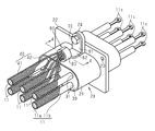
- the wire harness 10 is routed to, for example, a hybrid vehicle or an electric vehicle, and electrically connects one device 91 and a plurality (three in the present embodiment) of devices (not shown). Connecting.
- the wire harness 10 includes a plurality of (six in this embodiment) electric wires 11, a pair of connectors 20 into which both ends of the electric wires 11 are respectively inserted, and some or all of the plurality of electric wires 11. And at least one flexible protective tube 12.
- six electric wires 11 are divided into three protective tubes 12 and are accommodated, for example, two by two.
- the protective tube 12 is a corrugated tube made of, for example, a synthetic resin material.
- the connector 20 corresponds to a cylindrical member according to the present invention.
- each electric wire 11 has a core wire 11a and a cylindrical insulating coating 11b covering the outer periphery of the core wire 11a.
- the core wire 11a is a stranded wire formed by twisting together a plurality of metal strands made of, for example, a copper alloy.
- the insulating coating 11b is made of an electrically insulating synthetic resin material.
- a terminal 11c connected to the device 91 is fixed to the end of the core wire 11a.
- the terminal 11c is not intended to be limited, but may be a so-called round terminal.
- illustration of the protective tube 12 is abbreviate
- the configuration of the connector 20 will be described.
- the axial direction of the connector 20 may be simply referred to as the axial direction.
- the connector 20 is attached to a housing (not shown) of the device 91, and is provided in the central portion in the axial direction of the long cylindrical body 21 and the outer peripheral surface of the body 21.
- the flange 22 is provided.
- the connector 20 is integrally formed of a metal material such as an aluminum alloy.
- the flange 22 is provided with an attachment hole 23 for attachment to the device 91.
- a rectangular columnar support member 30 is inserted into the main body 21.
- the support member 30 is made of an elastic material such as rubber.
- the outer peripheral surface of the support member 30 and the inner peripheral surface of the main body 21 are in close contact with each other. Thereby, the space between the support member 30 and the main body portion 21 is sealed.
- the support member 30 is provided with a plurality of through holes 31 extending in the axial direction.
- six through holes 31 are provided in accordance with the number of electric wires 11.
- the electric wire 11 is inserted through each through hole 31.
- the outer peripheral surface of the electric wire 11 (specifically, the insulating coating 11b) and the inner peripheral surface of the through hole 31 are in close contact. Thereby, the space
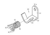
- a terminal member 60 called a so-called open barrel terminal is fixed to the seat portion 24 of the connector 20 via a screw 70.
- the terminal member 60 of the present embodiment is made of a conductive metal material such as an aluminum alloy.
- the terminal member 60 extends in the radial direction of the connector 20, and is bent at the base portion 61 in contact with the seat portion 24, and at the base portion 61 side of the connector 20 at the base portion 61.
- An extending portion 62 extending toward the side away from the flange 22 in the axial direction, and a barrel portion 63 connected to the extending portion 62.
- the base 61 is provided with an insertion hole 61 a through which the screw 70 is inserted.
- the wire harness 10 includes a plurality of shield members 40 each having a cylindrical portion 41 that covers a portion of the electric wire 11 located outside the connector 20.
- the shield member 40 is made of a braided wire in which conductive strands made of an aluminum alloy or the like are knitted into a cylindrical shape.
- the wire harness 10 of the present embodiment includes a number of shield members 40 corresponding to the number of electric wires 11. That is, one electric wire 11 is inserted through the cylindrical portion 41 of one shield member 40.
- An extending portion 42 that extends toward the connector 20 is provided at one end of the cylindrical portion 41 of each shield member 40.
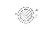
- Three extending portions 42 of the six shield members 40 are preliminarily gathered, and the first collecting portion 51 formed in a half columnar shape and the other three extending portions 42 are preliminarily gathered into a half circle.
- the second aggregated portion 52 formed in a columnar shape is crimped to the barrel portion 63 that forms the cylindrical shape of the terminal member 60 in a state of being attached to each other and gathered into a columnar shape.
- the wire harness 10 includes a cylindrical metal connector 20, a plurality of electric wires 11 inserted through the connector 20, and a braided wire in which conductive strands are knitted into a cylinder.
- a plurality of shield members 40 each having a cylindrical portion 41 that covers a portion of the electric wire 11 located outside the connector 20 are provided.
- the extending portions 42 provided at one end portions of the shield members 40 are fixed to the connector 20 in a state where they are gathered.
- the attaching operation of the shield member 40 to the connector 20 is simplified as compared with the configuration in which the extending portions 42 of the respective shield members 40 are separately fixed to the connector 20. Therefore, the plurality of shield members 40 can be easily attached to the connector 20.
- the extending portion 42 provided at one end of the plurality of shield members 40 is fixed to the connector 20 via the conductive terminal member 60.
- the extended portion 42 of each shield member 40 is fixed to the terminal member 60, and the terminal member 60 is fixed to the connector 20, thereby fixing the extended portion 42 of each shield member 40 to the connector 20. be able to.
- the attaching operation of the shield member 40 to the connector 20 is simplified as compared with the aspect in which the extending portion 42 of each shield member 40 is directly fixed to the connector 20 by soldering or the like.
- the extending portion 42 provided at one end of the plurality of shield members 40 is pressure-bonded to the terminal member 60.
- the extended portion 42 of each shield member 40 is fixed to the terminal member 60 by crimping the extended portion 42 of each shield member 40 together with the terminal member 60. For this reason, the fixing work of the extended portion 42 of each shield member 40 and the terminal member 60 is simplified.
- the second collecting portion 52 in which the portions 42 are gathered together is crimped to the terminal member 60 in a gathered state.
- the terminal member 60 is fixed to the seat portion 24 of the connector 20 via the screw 70. According to such a configuration, the terminal member 60 can be easily fixed to the connector 20 by a simple mode in which the terminal member 60 is fixed to the connector 20 with the screw 70.
- the fixing mode of the terminal member 60 with respect to the connector 20 is not limited to that via the screw 70.
- Other fixing modes such as soldering and welding can also be employed.
- the seat portion 24 can be omitted.
- the terminal member 60 is not limited to the so-called open barrel terminal exemplified in the above embodiment, and may be a closed barrel terminal having a cylindrical barrel portion.
- the extended portion 42 provided at one end portion of each shield member 40 is exemplified as the first aggregated portion 51 or the second aggregated portion 52, but all the shield members 40
- the extending part 42 may be gathered together in advance. Note that the shape in which the extending portions 42 of each shield member 40 are gathered is not limited to a cylindrical shape, and can be changed to any shape such as a prismatic shape.
- each shield member 40 and the terminal member 60 is not limited to crimping
- Other fixing modes such as soldering and welding can be employed.
- -It can also be fastened and fixed by metal caulking etc. in the state where the part where one end part of each shield member 40 was put together was along the outer peripheral surface of connector 20.
- the gathered portions of the shield members 40 can be stably fastened to the connector 20.
- a portion where one end portions of the shield members 40 are gathered with respect to the connector 20 may be directly fixed by soldering or welding.
- a plurality of electric wires 11 may be covered with the cylindrical portion 41 of one shield member 40.
- the cylindrical member is embodied as the connector 20 provided at the end of the electric wire 11, but the cylindrical member according to the present invention is not limited to this, and is provided at the central portion in the length direction of the electric wire 11. It may be embodied as provided.
- the first collecting portion 51 is, for example, a halved cylinder at the distal end portion of the extending portion 42 of the first subset (for example, three shielding members 40) of the plurality of shielding members 40. It may be called the 1st conductive block formed by shape
- the second aggregated portion 52 has a second predetermined shape that can be, for example, a half cylinder, at the distal end portion of the extended portion 42 of the second subset (for example, the remaining three shield members 40) of the plurality of shield members 40. It may be called the 2nd conductive block formed by shape
- a caulking portion formed by combining a plurality of conductive blocks including the first and second conductive blocks (51, 52) and caulked by the barrel portion 63 has a third predetermined shape which may be a columnar shape. Sometimes referred to as a single terminal conductive block or terminal large diameter.
- the plurality of shield members 40 are electrically connected to the main body portion 21 of the connector 20 via the terminal member 60 and the seat portion 24.
- the first predetermined shape of the first conductive block and the second predetermined shape of the second conductive block may be the same, but may be different.
- the third predetermined shape of the single terminal conductive block may be different from the first and second predetermined shapes of the first and second conductive blocks, but may be the same.
- the main body 21 of the connector 20 may be called a connector housing or a connector hood.
- the base 61 and the extension 62 of the terminal member 60 may be referred to as an L-shaped bracket of the terminal member 60.
- the base portion 61 may be referred to as a flat plate-like bent piece that is bent with respect to the extending portion 62.
- a wire harness (10) according to some mounting examples is made of a metal cylindrical connector hood (21) and a plurality of wires (11) inserted through the connector hood (21).
- Each of the electric wires (11) includes a first length portion covered with the connector hood (21) and a second length portion not covered with the connector hood (21).
- the plurality of flexible shield members (40) covering each of the second length portions not present, the plurality of flexible shield members (40), and the connector hood (21) are fixedly connected and electrically Single to connect to A terminal member (60), and one end of each of the plurality of flexible shield members (40) does not cover the outer surface of the corresponding electric wire (11), and is away from the outer surface of the corresponding electric wire (11).
- the one end portions of the plurality of flexible shield members (40) are grouped into a single terminal conductive block, and the single terminal conductive block is the single terminal conductive block.
- One terminal member (60) is fixedly and electrically connected to the connector hood (21).
- the tip portion of the first subset of the first predetermined number of shield members (40) among the plurality of shield members (40) is formed into the first conductive block.
- the tip portion of the second subset consisting of the second predetermined number of shield members (40) of the plurality of shield members (40) is integrated with the second conductive block.
- the single terminal conductive block is a large terminal end portion formed by combining the first conductive block and the second conductive block.
- the single terminal member (60) includes an L-shaped bracket (61, 61) for fixing the single terminal member (60) to the connector hood (21). 62) and a barrel part (63) for caulking the single terminal conductive block.
- the L-shaped brackets (61, 62) of the single terminal member (60) have a flat plate-like extension (in contact with the outer surface of the connector hood (21)). 62) and a flat bent piece (61) which is bent with respect to the flat extension portion (62) and protrudes in a direction orthogonal to the outer surface of the connector hood (21).
Abstract
ワイヤハーネス10は、金属製のコネクタ20と、コネクタ20に挿通された複数本の電線11と、導電性の素線が筒状に編み込まれた編組線からなり、各電線11のうちコネクタ20の外側に位置する部分をそれぞれ覆う筒状部41を有する複数のシールド部材40とを備える。各シールド部材40の一端部に設けられた延設部42が纏められた状態でコネクタ20に固定されている。
Description
本発明は、ワイヤハーネスに関する。
従来、金属製の筒状部材と、筒状部材に挿通された複数本の電線と、導電性の素線が筒状に編み込まれた編組線からなり、複数本の電線のうち筒状部材の外側に位置する部分を覆う金属製のシールド部材とを備えたワイヤハーネスがある(例えば特許文献1参照)。
特許文献1に記載のワイヤハーネスにおいては、2つの第2電線(以下、電線)のうち筒状部材の外側に位置する部分が第2シールド部材(以下、シールド部材)によって覆われている。シールド部材の一端部に形成された接続部が筒状部材の外周面に沿った状態でカシメリングにより外周側から留められている。
こうしたワイヤハーネスにおいては、電線への通電に伴って発生する電磁ノイズが、シールド部材により吸収される。また、電磁ノイズを吸収することによってシールド部材に蓄えられた電荷は、上記接続部から筒状部材を介してグランドに放出される。
ところで、複数のシールド部材の接続部を筒状部材の外周面に対してカシメリングにより外周側から留める場合には、以下の不都合が生じるおそれがある。すなわち、筒状部材の外周面に対して各接続部を沿わせた状態でカシメリングを取り付ける必要がある他、カシメリングを取り付ける際に各接続部が撓むことから、各接続部の取付位置が安定せず、取付作業が煩雑になる。
本発明の目的は、複数のシールド部材を筒状部材に対して容易に取り付けることのできるワイヤハーネスを提供することにある。
上記目的を達成するためのワイヤハーネスは、金属製の筒状部材と、前記筒状部材に挿通された複数本の電線と、導電性の素線が筒状に編み込まれた編組線からなり、前記電線のうち前記筒状部材の外側に位置する部分をそれぞれ覆う筒状部を有する複数のシールド部材と、を備え、前記複数のシールド部材の一端部が纏められた状態で前記筒状部材に固定されている。
この構成によれば、各シールド部材の一端部が別々に筒状部材に固定される構成に比べて、筒状部材に対するシールド部材の取付作業が簡単になる。
また例えば、各シールド部材の一端部が纏められた部分を筒状部材の外周面に沿わせた状態でバンドにより留める場合には、筒状部材に対して当該纏められた部分を安定して留めることができる。
また例えば、各シールド部材の一端部が纏められた部分を筒状部材の外周面に沿わせた状態でバンドにより留める場合には、筒状部材に対して当該纏められた部分を安定して留めることができる。
上記ワイヤハーネスにおいて、前記複数のシールド部材の一端部が導電性の端子部材を介して前記筒状部材に固定されていることが好ましい。
この構成によれば、各シールド部材の一端部を端子部材に固定し、この端子部材を筒状部材に固定することにより、各シールド部材の一端部を筒状部材に固定することができる。このため、はんだ付けなどにより各シールド部材の一端部を筒状部材に対して直接固定する態様に比べて、筒状部材に対するシールド部材の取付作業が簡単になる。
この構成によれば、各シールド部材の一端部を端子部材に固定し、この端子部材を筒状部材に固定することにより、各シールド部材の一端部を筒状部材に固定することができる。このため、はんだ付けなどにより各シールド部材の一端部を筒状部材に対して直接固定する態様に比べて、筒状部材に対するシールド部材の取付作業が簡単になる。
上記ワイヤハーネスにおいて、前記複数のシールド部材の一端部が前記端子部材に圧着されていることが好ましい。
この構成によれば、端子部材と共に各シールド部材の一端部を圧着することにより、各シールド部材の一端部が端子部材に固定される。このため、各シールド部材の一端部と端子部材との固定作業が簡単となる。
この構成によれば、端子部材と共に各シールド部材の一端部を圧着することにより、各シールド部材の一端部が端子部材に固定される。このため、各シールド部材の一端部と端子部材との固定作業が簡単となる。
上記ワイヤハーネスにおいて、前記複数のシールド部材のうちの一部が予め纏められた第1集合部と、前記複数のシールド部材のうちの前記一部以外の他部が予め纏められた第2集合部とが、纏められた状態で前記端子部材に圧着されていることが好ましい。
この構成によれば、各シールド部材のうちの一部が纏められた第1集合部と、他部が纏められた第2集合部とを纏めた状態で端子部材に圧着すれば済むため、各シールド部材の一端部を端子部材に圧着する作業が簡単となる。
上記ワイヤハーネスにおいて、前記端子部材は締結部材を介して前記筒状部材に固定されていることが好ましい。
この構成によれば、締結部材により端子部材を筒状部材に対して固定するといった簡単な態様により、端子部材を筒状部材に対して容易に固定することができる。
この構成によれば、締結部材により端子部材を筒状部材に対して固定するといった簡単な態様により、端子部材を筒状部材に対して容易に固定することができる。
上記ワイヤハーネスにおいて、前記筒状部材には、前記締結部材が締結される座部が設けられていることが好ましい。
この構成によれば、筒状部材の座部に締結部材を締結することにより、筒状部材に締結部材を容易に固定することができる。
この構成によれば、筒状部材の座部に締結部材を締結することにより、筒状部材に締結部材を容易に固定することができる。
本発明のいくつかの態様に従うワイヤハーネスによれば、複数のシールド部材を筒状部材に対して容易に取り付けることができる。
以下、ワイヤハーネスの一実施形態について説明する。
図1に示すように、ワイヤハーネス10は、例えばハイブリッド車や電気自動車に配索されるものであり、1つの機器91と図示しない複数(本実施形態では3つ)の機器とを電気的に接続する。
図1に示すように、ワイヤハーネス10は、例えばハイブリッド車や電気自動車に配索されるものであり、1つの機器91と図示しない複数(本実施形態では3つ)の機器とを電気的に接続する。
ワイヤハーネス10は、複数本(本実施形態では6本)の電線11と、電線11の両端部がそれぞれ挿通された一対のコネクタ20と、複数の電線11のうちのいくつかまたは全てを一括して収容する少なくとも一つの可撓性の保護管12とを備えている。図1の例では、6本の電線11が3本の保護管12に分かれて、例えば2本ずつ、収容されている。保護管12は、例えば合成樹脂材料からなるコルゲートチューブである。なお、コネクタ20が本発明にかかる筒状部材に相当する。
図2に示すように、各電線11は、芯線11aと芯線11aの外周を覆う円筒状の絶縁被覆11bとを有している。芯線11aは、例えば、銅合金からなる複数本の金属素線を撚り合わせて形成される撚り線である。絶縁被覆11bは、電気絶縁性の合成樹脂材料からなる。芯線11aの端部には、機器91に接続される端子11cが固定されている。端子11cは、限定を意図しないが、いわゆる丸端子であり得る。なお、図2では、保護管12の図示を省略している。
<コネクタ20>
次に、コネクタ20の構成について説明する。なお、以降において、コネクタ20の軸線方向を単に軸線方向と称することがある。
次に、コネクタ20の構成について説明する。なお、以降において、コネクタ20の軸線方向を単に軸線方向と称することがある。
図2に示すように、コネクタ20は、機器91の筐体(図示略)に取り付けられるものであり、長円筒状の本体部21及び本体部21の外周面のうち軸線方向における中央部に設けられたフランジ22を有している。コネクタ20は、アルミニウム合金などの金属材料により一体形成されている。フランジ22には、機器91に取り付けるための取付孔23が設けられている。
本体部21の外周面のうちフランジ22よりも電線11の端末側とは反対側の部分、すなわち機器91の筐体の外側に位置する部分には、ねじ孔(図示略)を有する座部24が突設されている。
本体部21の内部には、長方形柱状の支持部材30が挿入されている。支持部材30はゴムなどの弾性材料からなる。支持部材30の外周面と本体部21の内周面とが密着している。これにより、支持部材30と本体部21との間がシールされている。
支持部材30には、軸線方向に延在する複数の貫通孔31が設けられている。本実施形態では、電線11の数に合わせて、6つの貫通孔31が設けられている。
各貫通孔31には、電線11が挿通されている。電線11(詳しくは、絶縁被覆11b)の外周面と貫通孔31の内周面とが密着している。これにより、電線11と支持部材30との間がシールされている。
各貫通孔31には、電線11が挿通されている。電線11(詳しくは、絶縁被覆11b)の外周面と貫通孔31の内周面とが密着している。これにより、電線11と支持部材30との間がシールされている。
<端子部材60>
図2に示すように、コネクタ20の座部24には、ねじ70を介して所謂オープンバレル端子と称される端子部材60が固定されている。本実施形態の端子部材60は、アルミニウム合金などの導電性の金属材料からなる。
図2に示すように、コネクタ20の座部24には、ねじ70を介して所謂オープンバレル端子と称される端子部材60が固定されている。本実施形態の端子部材60は、アルミニウム合金などの導電性の金属材料からなる。
図2及び図3に示すように、端子部材60は、コネクタ20の径方向に延在し、座部24に当接された基部61、基部61におけるコネクタ20の本体部21側にて屈曲され、軸線方向においてフランジ22から離間する側に向けて延在する延在部62、及び延在部62に連結されたバレル部63を有している。
図3に示すように、基部61には、ねじ70が挿通される挿通孔61aが設けられている。
<シールド部材40>
図2~図4に示すように、ワイヤハーネス10は、電線11のうちコネクタ20の外側に位置する部分をそれぞれ覆う筒状部41を有する複数のシールド部材40を備えている。シールド部材40は、アルミニウム合金などからなる導電性の素線が筒状に編み込まれた編組線からなる。本実施形態のワイヤハーネス10は、電線11の数に対応する数のシールド部材40を備えている。すなわち、1つのシールド部材40の筒状部41に1本の電線11が挿通されている。
<シールド部材40>
図2~図4に示すように、ワイヤハーネス10は、電線11のうちコネクタ20の外側に位置する部分をそれぞれ覆う筒状部41を有する複数のシールド部材40を備えている。シールド部材40は、アルミニウム合金などからなる導電性の素線が筒状に編み込まれた編組線からなる。本実施形態のワイヤハーネス10は、電線11の数に対応する数のシールド部材40を備えている。すなわち、1つのシールド部材40の筒状部41に1本の電線11が挿通されている。
各シールド部材40の筒状部41の一端部には、コネクタ20に向けて延びる延設部42が設けられている。
6つのシールド部材40のうちの3つの延設部42が予め纏められ、半割円柱状に形成された第1集合部51と、他の3つの延設部42が予め纏められ、半割円柱状に形成された第2集合部52とが、互いに付き合わされて円柱状に纏められた状態で端子部材60の円筒状をなすバレル部63に圧着されている。
6つのシールド部材40のうちの3つの延設部42が予め纏められ、半割円柱状に形成された第1集合部51と、他の3つの延設部42が予め纏められ、半割円柱状に形成された第2集合部52とが、互いに付き合わされて円柱状に纏められた状態で端子部材60の円筒状をなすバレル部63に圧着されている。
本実施形態の作用及び効果について説明する。
(1)ワイヤハーネス10は、筒状をなす金属製のコネクタ20と、コネクタ20に挿通された複数本の電線11と、導電性の素線が筒状に編み込まれた編組線からなり、各電線11のうちコネクタ20の外側に位置する部分をそれぞれ覆う筒状部41を有する複数のシールド部材40とを備えている。各シールド部材40の一端部に設けられた延設部42が纏められた状態でコネクタ20に固定されている。
(1)ワイヤハーネス10は、筒状をなす金属製のコネクタ20と、コネクタ20に挿通された複数本の電線11と、導電性の素線が筒状に編み込まれた編組線からなり、各電線11のうちコネクタ20の外側に位置する部分をそれぞれ覆う筒状部41を有する複数のシールド部材40とを備えている。各シールド部材40の一端部に設けられた延設部42が纏められた状態でコネクタ20に固定されている。
こうした構成によれば、各シールド部材40の延設部42が別々にコネクタ20に固定される構成に比べて、コネクタ20に対するシールド部材40の取付作業が簡単になる。したがって、複数のシールド部材40をコネクタ20に対して容易に取り付けることができる。
(2)複数のシールド部材40の一端部に設けられた延設部42が導電性の端子部材60を介してコネクタ20に固定されている。
こうした構成によれば、各シールド部材40の延設部42を端子部材60に固定し、端子部材60をコネクタ20に固定することにより、各シールド部材40の延設部42をコネクタ20に固定することができる。このため、はんだ付けなどにより各シールド部材40の延設部42をコネクタ20に対して直接固定する態様に比べて、コネクタ20に対するシールド部材40の取付作業が簡単になる。
こうした構成によれば、各シールド部材40の延設部42を端子部材60に固定し、端子部材60をコネクタ20に固定することにより、各シールド部材40の延設部42をコネクタ20に固定することができる。このため、はんだ付けなどにより各シールド部材40の延設部42をコネクタ20に対して直接固定する態様に比べて、コネクタ20に対するシールド部材40の取付作業が簡単になる。
(3)複数のシールド部材40の一端部に設けられた延設部42が端子部材60に圧着されている。端子部材60と共に各シールド部材40の延設部42をかしめて圧着することにより、各シールド部材40の延設部42が端子部材60に固定される。このため、各シールド部材40の延設部42と端子部材60との固定作業が簡単となる。
(4)複数のシールド部材40のうちの一部の各延設部42が予め纏められた第1集合部51と、複数のシールド部材40のうちの上記一部以外の他部の各延設部42が予め纏められた第2集合部52とが、纏められた状態で端子部材60に圧着されている。
こうした構成によれば、各シールド部材40のうちの一部の延設部42が纏められた第1集合部51と、他部の延設部42が纏められた第2集合部52とを纏めた状態で端子部材60に圧着すれば済むため、各シールド部材40の延設部42を端子部材60に圧着する作業が簡単となる。
(5)端子部材60はねじ70を介してコネクタ20の座部24に固定されている。
こうした構成によれば、ねじ70により端子部材60をコネクタ20に対して固定するといった簡単な態様により、端子部材60をコネクタ20に対して容易に固定することができる。
こうした構成によれば、ねじ70により端子部材60をコネクタ20に対して固定するといった簡単な態様により、端子部材60をコネクタ20に対して容易に固定することができる。
本実施形態は、以下のように変更して実施することができる。本実施形態及び以下の変更例は、技術的に矛盾しない範囲で互いに組み合わせて実施することができるなお、上記実施形態は、以下のように変更してもよい。
・コネクタ20に対する端子部材60の固定態様は、ねじ70を介したものに限定されない。はんだ付けや溶着など他の固定態様を採用することもできる。この場合、座部24を省略することもできる。
・端子部材60は、上記実施形態にて例示した所謂オープンバレル端子に限定されず、円筒状をなすバレル部を有するクローズドバレル端子であってもよい。
・上記実施形態では、各シールド部材40の一端部に設けられた延設部42が予め第1集合部51または第2集合部52として纏められたものについて例示したが、全てのシールド部材40の延設部42が予め1つに纏められているものであってもよい。なお、各シールド部材40の延設部42が纏められた形状は、円柱状をなすものに限定されず、例えば角柱状など任意の形状に変更することができる。
・上記実施形態では、各シールド部材40の一端部に設けられた延設部42が予め第1集合部51または第2集合部52として纏められたものについて例示したが、全てのシールド部材40の延設部42が予め1つに纏められているものであってもよい。なお、各シールド部材40の延設部42が纏められた形状は、円柱状をなすものに限定されず、例えば角柱状など任意の形状に変更することができる。
・各シールド部材40の一端部と端子部材60との固定態様は、圧着に限定されない。はんだ付けや溶着など他の固定態様を採用することができる。
・各シールド部材40の一端部が纏められた部分をコネクタ20の外周面に沿わせた状態で金属製のカシメリングなどにより締結して固定することもできる。この場合には、コネクタ20に対して各シールド部材40の纏められた部分を安定して締結することができる。またこの場合、コネクタ20に対して各シールド部材40の一端部が纏められた部分を、はんだ付けや溶着などにより直接固定してもよい。
・各シールド部材40の一端部が纏められた部分をコネクタ20の外周面に沿わせた状態で金属製のカシメリングなどにより締結して固定することもできる。この場合には、コネクタ20に対して各シールド部材40の纏められた部分を安定して締結することができる。またこの場合、コネクタ20に対して各シールド部材40の一端部が纏められた部分を、はんだ付けや溶着などにより直接固定してもよい。
・複数本の電線11を1つのシールド部材40の筒状部41によって覆うようにしてもよい。
・上記実施形態では、電線11の端部に設けられるコネクタ20として筒状部材を具体化したが、本発明にかかる筒状部材は、これに限らず、電線11の長さ方向の中央部分に設けられるものとして具体化してもよい。
・上記実施形態では、電線11の端部に設けられるコネクタ20として筒状部材を具体化したが、本発明にかかる筒状部材は、これに限らず、電線11の長さ方向の中央部分に設けられるものとして具体化してもよい。
・図3の例において、第1集合部51は、複数のシールド部材40のうちの第1のサブセット(例えば3つのシールド部材40)の延設部42の先端部分を、例えば半割円柱であり得る第1所定形状に成形することによって形成される第1導電性ブロックと呼称することがある。第2集合部52は、複数のシールド部材40のうちの第2のサブセット(例えば残りの3つのシールド部材40)の延設部42の先端部分を、例えば半割円柱であり得る第2所定形状に成形することによって形成される第2導電性ブロックと呼称することがある。第1及び第2導電性ブロック(51,52)を含む複数の導電性ブロックを合体して形成され、バレル部63によってカシメられる被カシメ部は、円柱状であり得る第3の所定形状を有する単一の末端導電性ブロックまたは末端大径部と呼称することがある。この単一の末端導電性ブロックの外面を端子部材60のバレル部63によってカシメることによって、複数のシールド部材40は、端子部材60及び座部24を介して、コネクタ20の本体部21と電気的に接続される。第1導電性ブロックの第1所定形状と第2導電性ブロックの第2所定形状とは同じであり得るが、異なってもよい。単一の末端導電性ブロックの第3所定形状は、第1及び第2導電性ブロックの第1及び第2所定形状と異なり得るが、同じでもよい。
・コネクタ20の本体部21は、コネクタハウジングまたはコネクタフードと呼称することがある。
・端子部材60の基部61と延在部62は、端子部材60のL字状ブラケットと呼称することがある。基部61は、延在部62に対して折り曲げられた平板状の折り曲げ片と呼称することがある。
・端子部材60の基部61と延在部62は、端子部材60のL字状ブラケットと呼称することがある。基部61は、延在部62に対して折り曲げられた平板状の折り曲げ片と呼称することがある。
本開示は以下の実装例を包含する。限定のためでなく理解の補助として実施形態の構成要素の参照符号を付した。
[付記1]いくつかの実装例に従うワイヤハーネス(10)は、金属製で筒状のコネクタフード(21)と、前記コネクタフード(21)に挿通された複数本の電線(11)であって、各電線(11)が、前記コネクタフード(21)に覆われている第1の長さ部分と、前記コネクタフード(21)に覆われていない第2の長さ部分とを含む、前記複数本の電線(11)と、各々が導電性の編組筒である複数の柔軟なシールド部材(40)であって、前記複数の電線(11)の各々において前記コネクタフード(21)に覆われていない前記第2の長さ部分をそれぞれ覆う前記複数の柔軟なシールド部材(40)と、前記複数の柔軟なシールド部材(40)と前記コネクタフード(21)とを固定的に連結しかつ電気的に接続するための単一の端子部材(60)とを備え、前記複数の柔軟なシールド部材(40)の各々の一端部は、対応する電線(11)の外面を覆っておらず、対応する電線(11)の外面から遠ざかるように引き出されており、前記複数の柔軟なシールド部材(40)の複数の前記一端部は、単一の末端導電性ブロックにまとめられており、前記単一の末端導電性ブロックは、前記単一の端子部材(60)によって、前記コネクタフード(21)に固定的にかつ電気的に接続されている。
[付記1]いくつかの実装例に従うワイヤハーネス(10)は、金属製で筒状のコネクタフード(21)と、前記コネクタフード(21)に挿通された複数本の電線(11)であって、各電線(11)が、前記コネクタフード(21)に覆われている第1の長さ部分と、前記コネクタフード(21)に覆われていない第2の長さ部分とを含む、前記複数本の電線(11)と、各々が導電性の編組筒である複数の柔軟なシールド部材(40)であって、前記複数の電線(11)の各々において前記コネクタフード(21)に覆われていない前記第2の長さ部分をそれぞれ覆う前記複数の柔軟なシールド部材(40)と、前記複数の柔軟なシールド部材(40)と前記コネクタフード(21)とを固定的に連結しかつ電気的に接続するための単一の端子部材(60)とを備え、前記複数の柔軟なシールド部材(40)の各々の一端部は、対応する電線(11)の外面を覆っておらず、対応する電線(11)の外面から遠ざかるように引き出されており、前記複数の柔軟なシールド部材(40)の複数の前記一端部は、単一の末端導電性ブロックにまとめられており、前記単一の末端導電性ブロックは、前記単一の端子部材(60)によって、前記コネクタフード(21)に固定的にかつ電気的に接続されている。
[付記2]いくつかの実装例では、前記複数のシールド部材(40)のうちの第1の所定数のシールド部材(40)からなる第1のサブセットの先端部分は、第1導電性ブロックに一体化されており、前記複数のシールド部材(40)のうちの第2の所定数のシールド部材(40)からなる第2のサブセットの先端部分は、第2導電性ブロックに一体化されており、前記単一の末端導電性ブロックは、前記第1導電性ブロックと前記第2導電性ブロックとが合体されて形成される末端大径部である。
[付記3]いくつかの実装例では、前記単一の端子部材(60)は、前記単一の端子部材(60)を前記コネクタフード(21)に固定するためのL字状ブラケット(61,62)と、前記単一の末端導電性ブロックをカシメるためのバレル部(63)とを含むワンピース品である。
[付記4]いくつかの実装例では、前記単一の端子部材(60)のL字状ブラケット(61,62)は、前記コネクタフード(21)の外面に接触する平板状の延在部(62)と、前記平板状の延在部(62)に対して折り曲げられ、前記コネクタフード(21)の前記外面に対して直交する方向に突出する平板状の折り曲げ片(61)とを含む。
本発明がその技術的思想から逸脱しない範囲で他の特有の形態で具体化されてもよいということは当業者にとって明らかであろう。例えば、実施形態(あるいはその1つ又は複数の態様)において説明した部品のうちの一部を省略したり、いくつかの部品を組合せてもよい。本発明の範囲は、添付の請求の範囲を参照して、請求の範囲が権利を与えられる均等物の全範囲と共に確定されるべきである。
10…ワイヤハーネス、11…電線、11a…芯線、11b…絶縁被覆、11c…端子、12…保護管、20…コネクタ(筒状部材)、21…本体部、22…フランジ、23…取付孔、24…座部、30…支持部材、31…貫通孔、40…シールド部材、41…筒状部、42…延設部、51…第1集合部、52…第2集合部、60…端子部材、61…基部、61a…挿通孔、62…延在部、63…バレル部、70…ねじ(締結部材)、91…機器。
Claims (6)
- 金属製の筒状部材と、
前記筒状部材に挿通された複数本の電線と、
導電性の素線が筒状に編み込まれた編組線からなり、前記電線のうち前記筒状部材の外側に位置する部分をそれぞれ覆う筒状部を有する複数のシールド部材と、を備え、
前記複数のシールド部材の一端部が纏められた状態で前記筒状部材に固定されている、
ワイヤハーネス。 - 前記複数のシールド部材の前記一端部が導電性の端子部材を介して前記筒状部材に固定されている、
請求項1に記載のワイヤハーネス。 - 前記複数のシールド部材の前記一端部が前記端子部材に圧着されている、
請求項2に記載のワイヤハーネス。 - 前記複数のシールド部材のうちの一部が予め纏められた第1集合部と、前記複数のシールド部材のうちの前記一部以外の他部が予め纏められた第2集合部とが、纏められた状態で前記端子部材に圧着されている、
請求項3に記載のワイヤハーネス。 - 前記端子部材は締結部材を介して前記筒状部材に固定されている、
請求項2~請求項4のいずれか一項に記載のワイヤハーネス。 - 前記筒状部材には、前記締結部材が締結される座部が設けられている、
請求項5に記載のワイヤハーネス。
Priority Applications (2)
| Application Number | Priority Date | Filing Date | Title |
|---|---|---|---|
| US16/980,777 US11335476B2 (en) | 2018-03-30 | 2019-03-11 | Wire harness |
| CN201980018454.2A CN111837202B (zh) | 2018-03-30 | 2019-03-11 | 线束 |
Applications Claiming Priority (2)
| Application Number | Priority Date | Filing Date | Title |
|---|---|---|---|
| JP2018069922A JP6819641B2 (ja) | 2018-03-30 | 2018-03-30 | ワイヤハーネス |
| JP2018-069922 | 2018-03-30 |
Publications (1)
| Publication Number | Publication Date |
|---|---|
| WO2019188163A1 true WO2019188163A1 (ja) | 2019-10-03 |
Family
ID=68061593
Family Applications (1)
| Application Number | Title | Priority Date | Filing Date |
|---|---|---|---|
| PCT/JP2019/009570 WO2019188163A1 (ja) | 2018-03-30 | 2019-03-11 | ワイヤハーネス |
Country Status (4)
| Country | Link |
|---|---|
| US (1) | US11335476B2 (ja) |
| JP (1) | JP6819641B2 (ja) |
| CN (1) | CN111837202B (ja) |
| WO (1) | WO2019188163A1 (ja) |
Families Citing this family (1)
| Publication number | Priority date | Publication date | Assignee | Title |
|---|---|---|---|---|
| JP2024032240A (ja) * | 2022-08-29 | 2024-03-12 | 住友電装株式会社 | ワイヤハーネス |
Citations (3)
| Publication number | Priority date | Publication date | Assignee | Title |
|---|---|---|---|---|
| JP2004319196A (ja) * | 2003-04-15 | 2004-11-11 | Auto Network Gijutsu Kenkyusho:Kk | シールド接続構造 |
| JP2008041479A (ja) * | 2006-08-08 | 2008-02-21 | Gs Eletech:Kk | 編組シールド被覆電線の保持装置 |
| JP2012234761A (ja) * | 2011-05-09 | 2012-11-29 | Sumitomo Electric Ind Ltd | ケーブルの製造方法およびケーブル |
Family Cites Families (8)
| Publication number | Priority date | Publication date | Assignee | Title |
|---|---|---|---|---|
| JP3346313B2 (ja) * | 1999-01-11 | 2002-11-18 | 住友電装株式会社 | シールド用編み線のアース接続構造 |
| JP2004172476A (ja) * | 2002-11-21 | 2004-06-17 | Auto Network Gijutsu Kenkyusho:Kk | シールド機能を備えた導電路 |
| JP4511988B2 (ja) | 2005-04-27 | 2010-07-28 | 株式会社オートネットワーク技術研究所 | シールド導電路 |
| KR101538806B1 (ko) * | 2009-03-16 | 2015-07-22 | 타이코에이엠피(유) | 차폐용 편조선의 쉘커버 |
| JP5766644B2 (ja) * | 2012-03-26 | 2015-08-19 | 株式会社フジクラ | 編組シールド電線の接続構造及びシールドワイヤハーネスの製造方法 |
| JP5915515B2 (ja) * | 2012-12-25 | 2016-05-11 | 日立金属株式会社 | ワイヤハーネス、及びシールドシェルと編組シールドとの接続構造 |
| EP3518642B1 (en) * | 2016-09-26 | 2022-07-27 | Furukawa Electric Co., Ltd. | Electromagnetic shield structure and wire harness |
| CN211700805U (zh) * | 2020-02-29 | 2020-10-16 | 一汽解放汽车有限公司 | 一种线束屏蔽层搭接装置 |
-
2018
- 2018-03-30 JP JP2018069922A patent/JP6819641B2/ja active Active
-
2019
- 2019-03-11 WO PCT/JP2019/009570 patent/WO2019188163A1/ja active Application Filing
- 2019-03-11 CN CN201980018454.2A patent/CN111837202B/zh active Active
- 2019-03-11 US US16/980,777 patent/US11335476B2/en active Active
Patent Citations (3)
| Publication number | Priority date | Publication date | Assignee | Title |
|---|---|---|---|---|
| JP2004319196A (ja) * | 2003-04-15 | 2004-11-11 | Auto Network Gijutsu Kenkyusho:Kk | シールド接続構造 |
| JP2008041479A (ja) * | 2006-08-08 | 2008-02-21 | Gs Eletech:Kk | 編組シールド被覆電線の保持装置 |
| JP2012234761A (ja) * | 2011-05-09 | 2012-11-29 | Sumitomo Electric Ind Ltd | ケーブルの製造方法およびケーブル |
Also Published As
| Publication number | Publication date |
|---|---|
| US20210012923A1 (en) | 2021-01-14 |
| JP6819641B2 (ja) | 2021-01-27 |
| CN111837202B (zh) | 2022-09-02 |
| JP2019179735A (ja) | 2019-10-17 |
| US11335476B2 (en) | 2022-05-17 |
| CN111837202A (zh) | 2020-10-27 |
Similar Documents
| Publication | Publication Date | Title |
|---|---|---|
| JP3786594B2 (ja) | 電磁波シールド編組 | |
| US10964456B2 (en) | Grommet and wire harness | |
| KR101480660B1 (ko) | 보호구, 보호구의 제조 방법 및 쉴드 도전체 | |
| CN110506375B (zh) | 线束 | |
| WO2019188231A1 (ja) | ワイヤハーネス | |
| JP2017117863A (ja) | シールド導電路 | |
| WO2019188163A1 (ja) | ワイヤハーネス | |
| WO2014148446A1 (ja) | 電線のシールド構造 | |
| CN109644583B (zh) | 电磁屏蔽部件及导电路径 | |
| WO2019188938A1 (ja) | ワイヤハーネス | |
| WO2019216227A1 (ja) | シールド電線の端末構造 | |
| WO2018173784A1 (ja) | 導電線 | |
| JP2012064331A (ja) | ワイヤーハーネス | |
| JP6183248B2 (ja) | 電磁シールド部材およびワイヤハーネス | |
| JP2003109707A (ja) | 簡易電磁波シールド構造およびその組立治具 | |
| JP2018101578A (ja) | 電線 | |
| US20230124892A1 (en) | Wire harness | |
| JP2017120917A (ja) | シールド導電路 | |
| JP6578228B2 (ja) | 編組導体とシールドシェルの接続構造、コネクタ付き電線、及び、編組導体とシールドシェルの接続方法 | |
| JP6784940B2 (ja) | 導電路 | |
| JP6281524B2 (ja) | ワイヤハーネス | |
| JP6628098B2 (ja) | シールド電線のアース処理構造 | |
| JP2015188023A (ja) | 電磁シールド部材 | |
| JP2022137454A (ja) | ワイヤーハーネスおよび接地構造体 | |
| JP2018101579A (ja) | ワイヤハーネス |
Legal Events
| Date | Code | Title | Description |
|---|---|---|---|
| 121 | Ep: the epo has been informed by wipo that ep was designated in this application |
Ref document number: 19774956 Country of ref document: EP Kind code of ref document: A1 |
|
| 122 | Ep: pct application non-entry in european phase |
Ref document number: 19774956 Country of ref document: EP Kind code of ref document: A1 |