WO2019167243A1 - 皮膜及びその形成方法 - Google Patents
皮膜及びその形成方法 Download PDFInfo
- Publication number
- WO2019167243A1 WO2019167243A1 PCT/JP2018/007942 JP2018007942W WO2019167243A1 WO 2019167243 A1 WO2019167243 A1 WO 2019167243A1 JP 2018007942 W JP2018007942 W JP 2018007942W WO 2019167243 A1 WO2019167243 A1 WO 2019167243A1
- Authority
- WO
- WIPO (PCT)
- Prior art keywords
- furnace
- ash
- film
- base layer
- coating
- Prior art date
- Legal status (The legal status is an assumption and is not a legal conclusion. Google has not performed a legal analysis and makes no representation as to the accuracy of the status listed.)
- Ceased
Links
Images





Classifications
-
- B—PERFORMING OPERATIONS; TRANSPORTING
- B05—SPRAYING OR ATOMISING IN GENERAL; APPLYING FLUENT MATERIALS TO SURFACES, IN GENERAL
- B05D—PROCESSES FOR APPLYING FLUENT MATERIALS TO SURFACES, IN GENERAL
- B05D1/00—Processes for applying liquids or other fluent materials
- B05D1/02—Processes for applying liquids or other fluent materials performed by spraying
-
- F—MECHANICAL ENGINEERING; LIGHTING; HEATING; WEAPONS; BLASTING
- F27—FURNACES; KILNS; OVENS; RETORTS
- F27D—DETAILS OR ACCESSORIES OF FURNACES, KILNS, OVENS OR RETORTS, IN SO FAR AS THEY ARE OF KINDS OCCURRING IN MORE THAN ONE KIND OF FURNACE
- F27D1/00—Casings; Linings; Walls; Roofs
- F27D1/0003—Linings or walls
- F27D1/0006—Linings or walls formed from bricks or layers with a particular composition or specific characteristics
-
- B—PERFORMING OPERATIONS; TRANSPORTING
- B05—SPRAYING OR ATOMISING IN GENERAL; APPLYING FLUENT MATERIALS TO SURFACES, IN GENERAL
- B05D—PROCESSES FOR APPLYING FLUENT MATERIALS TO SURFACES, IN GENERAL
- B05D3/00—Pretreatment of surfaces to which liquids or other fluent materials are to be applied; After-treatment of applied coatings, e.g. intermediate treating of an applied coating preparatory to subsequent applications of liquids or other fluent materials
- B05D3/02—Pretreatment of surfaces to which liquids or other fluent materials are to be applied; After-treatment of applied coatings, e.g. intermediate treating of an applied coating preparatory to subsequent applications of liquids or other fluent materials by baking
- B05D3/0254—After-treatment
-
- B—PERFORMING OPERATIONS; TRANSPORTING
- B05—SPRAYING OR ATOMISING IN GENERAL; APPLYING FLUENT MATERIALS TO SURFACES, IN GENERAL
- B05D—PROCESSES FOR APPLYING FLUENT MATERIALS TO SURFACES, IN GENERAL
- B05D5/00—Processes for applying liquids or other fluent materials to surfaces to obtain special surface effects, finishes or structures
-
- C—CHEMISTRY; METALLURGY
- C04—CEMENTS; CONCRETE; ARTIFICIAL STONE; CERAMICS; REFRACTORIES
- C04B—LIME, MAGNESIA; SLAG; CEMENTS; COMPOSITIONS THEREOF, e.g. MORTARS, CONCRETE OR LIKE BUILDING MATERIALS; ARTIFICIAL STONE; CERAMICS; REFRACTORIES; TREATMENT OF NATURAL STONE
- C04B35/00—Shaped ceramic products characterised by their composition; Ceramics compositions; Processing powders of inorganic compounds preparatory to the manufacturing of ceramic products
- C04B35/01—Shaped ceramic products characterised by their composition; Ceramics compositions; Processing powders of inorganic compounds preparatory to the manufacturing of ceramic products based on oxide ceramics
- C04B35/14—Shaped ceramic products characterised by their composition; Ceramics compositions; Processing powders of inorganic compounds preparatory to the manufacturing of ceramic products based on oxide ceramics based on silica
-
- C—CHEMISTRY; METALLURGY
- C04—CEMENTS; CONCRETE; ARTIFICIAL STONE; CERAMICS; REFRACTORIES
- C04B—LIME, MAGNESIA; SLAG; CEMENTS; COMPOSITIONS THEREOF, e.g. MORTARS, CONCRETE OR LIKE BUILDING MATERIALS; ARTIFICIAL STONE; CERAMICS; REFRACTORIES; TREATMENT OF NATURAL STONE
- C04B35/00—Shaped ceramic products characterised by their composition; Ceramics compositions; Processing powders of inorganic compounds preparatory to the manufacturing of ceramic products
- C04B35/622—Forming processes; Processing powders of inorganic compounds preparatory to the manufacturing of ceramic products
- C04B35/62222—Forming processes; Processing powders of inorganic compounds preparatory to the manufacturing of ceramic products obtaining ceramic coatings
-
- C—CHEMISTRY; METALLURGY
- C04—CEMENTS; CONCRETE; ARTIFICIAL STONE; CERAMICS; REFRACTORIES
- C04B—LIME, MAGNESIA; SLAG; CEMENTS; COMPOSITIONS THEREOF, e.g. MORTARS, CONCRETE OR LIKE BUILDING MATERIALS; ARTIFICIAL STONE; CERAMICS; REFRACTORIES; TREATMENT OF NATURAL STONE
- C04B41/00—After-treatment of mortars, concrete, artificial stone or ceramics; Treatment of natural stone
- C04B41/009—After-treatment of mortars, concrete, artificial stone or ceramics; Treatment of natural stone characterised by the material treated
-
- C—CHEMISTRY; METALLURGY
- C04—CEMENTS; CONCRETE; ARTIFICIAL STONE; CERAMICS; REFRACTORIES
- C04B—LIME, MAGNESIA; SLAG; CEMENTS; COMPOSITIONS THEREOF, e.g. MORTARS, CONCRETE OR LIKE BUILDING MATERIALS; ARTIFICIAL STONE; CERAMICS; REFRACTORIES; TREATMENT OF NATURAL STONE
- C04B41/00—After-treatment of mortars, concrete, artificial stone or ceramics; Treatment of natural stone
- C04B41/45—Coating or impregnating, e.g. injection in masonry, partial coating of green or fired ceramics, organic coating compositions for adhering together two concrete elements
- C04B41/52—Multiple coating or impregnating multiple coating or impregnating with the same composition or with compositions only differing in the concentration of the constituents, is classified as single coating or impregnation
-
- C—CHEMISTRY; METALLURGY
- C04—CEMENTS; CONCRETE; ARTIFICIAL STONE; CERAMICS; REFRACTORIES
- C04B—LIME, MAGNESIA; SLAG; CEMENTS; COMPOSITIONS THEREOF, e.g. MORTARS, CONCRETE OR LIKE BUILDING MATERIALS; ARTIFICIAL STONE; CERAMICS; REFRACTORIES; TREATMENT OF NATURAL STONE
- C04B41/00—After-treatment of mortars, concrete, artificial stone or ceramics; Treatment of natural stone
- C04B41/80—After-treatment of mortars, concrete, artificial stone or ceramics; Treatment of natural stone of only ceramics
- C04B41/81—Coating or impregnation
- C04B41/89—Coating or impregnation for obtaining at least two superposed coatings having different compositions
- C04B41/90—Coating or impregnation for obtaining at least two superposed coatings having different compositions at least one coating being a metal
-
- C—CHEMISTRY; METALLURGY
- C10—PETROLEUM, GAS OR COKE INDUSTRIES; TECHNICAL GASES CONTAINING CARBON MONOXIDE; FUELS; LUBRICANTS; PEAT
- C10J—PRODUCTION OF PRODUCER GAS, WATER-GAS, SYNTHESIS GAS FROM SOLID CARBONACEOUS MATERIAL, OR MIXTURES CONTAINING THESE GASES; CARBURETTING AIR OR OTHER GASES
- C10J3/00—Production of combustible gases containing carbon monoxide from solid carbonaceous fuels
- C10J3/72—Other features
- C10J3/74—Construction of shells or jackets
-
- C—CHEMISTRY; METALLURGY
- C23—COATING METALLIC MATERIAL; COATING MATERIAL WITH METALLIC MATERIAL; CHEMICAL SURFACE TREATMENT; DIFFUSION TREATMENT OF METALLIC MATERIAL; COATING BY VACUUM EVAPORATION, BY SPUTTERING, BY ION IMPLANTATION OR BY CHEMICAL VAPOUR DEPOSITION, IN GENERAL; INHIBITING CORROSION OF METALLIC MATERIAL OR INCRUSTATION IN GENERAL
- C23C—COATING METALLIC MATERIAL; COATING MATERIAL WITH METALLIC MATERIAL; SURFACE TREATMENT OF METALLIC MATERIAL BY DIFFUSION INTO THE SURFACE, BY CHEMICAL CONVERSION OR SUBSTITUTION; COATING BY VACUUM EVAPORATION, BY SPUTTERING, BY ION IMPLANTATION OR BY CHEMICAL VAPOUR DEPOSITION, IN GENERAL
- C23C26/00—Coating not provided for in groups C23C2/00 - C23C24/00
-
- C—CHEMISTRY; METALLURGY
- C23—COATING METALLIC MATERIAL; COATING MATERIAL WITH METALLIC MATERIAL; CHEMICAL SURFACE TREATMENT; DIFFUSION TREATMENT OF METALLIC MATERIAL; COATING BY VACUUM EVAPORATION, BY SPUTTERING, BY ION IMPLANTATION OR BY CHEMICAL VAPOUR DEPOSITION, IN GENERAL; INHIBITING CORROSION OF METALLIC MATERIAL OR INCRUSTATION IN GENERAL
- C23C—COATING METALLIC MATERIAL; COATING MATERIAL WITH METALLIC MATERIAL; SURFACE TREATMENT OF METALLIC MATERIAL BY DIFFUSION INTO THE SURFACE, BY CHEMICAL CONVERSION OR SUBSTITUTION; COATING BY VACUUM EVAPORATION, BY SPUTTERING, BY ION IMPLANTATION OR BY CHEMICAL VAPOUR DEPOSITION, IN GENERAL
- C23C28/00—Coating for obtaining at least two superposed coatings either by methods not provided for in a single one of groups C23C2/00 - C23C26/00 or by combinations of methods provided for in subclasses C23C and C25C or C25D
-
- F—MECHANICAL ENGINEERING; LIGHTING; HEATING; WEAPONS; BLASTING
- F22—STEAM GENERATION
- F22B—METHODS OF STEAM GENERATION; STEAM BOILERS
- F22B37/00—Component parts or details of steam boilers
- F22B37/02—Component parts or details of steam boilers applicable to more than one kind or type of steam boiler
- F22B37/10—Water tubes; Accessories therefor
-
- F—MECHANICAL ENGINEERING; LIGHTING; HEATING; WEAPONS; BLASTING
- F28—HEAT EXCHANGE IN GENERAL
- F28F—DETAILS OF HEAT-EXCHANGE AND HEAT-TRANSFER APPARATUS, OF GENERAL APPLICATION
- F28F19/00—Preventing the formation of deposits or corrosion, e.g. by using filters or scrapers
- F28F19/02—Preventing the formation of deposits or corrosion, e.g. by using filters or scrapers by using coatings, e.g. vitreous or enamel coatings
-
- C—CHEMISTRY; METALLURGY
- C04—CEMENTS; CONCRETE; ARTIFICIAL STONE; CERAMICS; REFRACTORIES
- C04B—LIME, MAGNESIA; SLAG; CEMENTS; COMPOSITIONS THEREOF, e.g. MORTARS, CONCRETE OR LIKE BUILDING MATERIALS; ARTIFICIAL STONE; CERAMICS; REFRACTORIES; TREATMENT OF NATURAL STONE
- C04B2235/00—Aspects relating to ceramic starting mixtures or sintered ceramic products
- C04B2235/02—Composition of constituents of the starting material or of secondary phases of the final product
- C04B2235/30—Constituents and secondary phases not being of a fibrous nature
- C04B2235/32—Metal oxides, mixed metal oxides, or oxide-forming salts thereof, e.g. carbonates, nitrates, (oxy)hydroxides, chlorides
-
- C—CHEMISTRY; METALLURGY
- C04—CEMENTS; CONCRETE; ARTIFICIAL STONE; CERAMICS; REFRACTORIES
- C04B—LIME, MAGNESIA; SLAG; CEMENTS; COMPOSITIONS THEREOF, e.g. MORTARS, CONCRETE OR LIKE BUILDING MATERIALS; ARTIFICIAL STONE; CERAMICS; REFRACTORIES; TREATMENT OF NATURAL STONE
- C04B2235/00—Aspects relating to ceramic starting mixtures or sintered ceramic products
- C04B2235/02—Composition of constituents of the starting material or of secondary phases of the final product
- C04B2235/30—Constituents and secondary phases not being of a fibrous nature
- C04B2235/32—Metal oxides, mixed metal oxides, or oxide-forming salts thereof, e.g. carbonates, nitrates, (oxy)hydroxides, chlorides
- C04B2235/3262—Manganese oxides, manganates, rhenium oxides or oxide-forming salts thereof, e.g. MnO
-
- C—CHEMISTRY; METALLURGY
- C04—CEMENTS; CONCRETE; ARTIFICIAL STONE; CERAMICS; REFRACTORIES
- C04B—LIME, MAGNESIA; SLAG; CEMENTS; COMPOSITIONS THEREOF, e.g. MORTARS, CONCRETE OR LIKE BUILDING MATERIALS; ARTIFICIAL STONE; CERAMICS; REFRACTORIES; TREATMENT OF NATURAL STONE
- C04B2235/00—Aspects relating to ceramic starting mixtures or sintered ceramic products
- C04B2235/02—Composition of constituents of the starting material or of secondary phases of the final product
- C04B2235/30—Constituents and secondary phases not being of a fibrous nature
- C04B2235/32—Metal oxides, mixed metal oxides, or oxide-forming salts thereof, e.g. carbonates, nitrates, (oxy)hydroxides, chlorides
- C04B2235/327—Iron group oxides, their mixed metal oxides, or oxide-forming salts thereof
- C04B2235/3272—Iron oxides or oxide forming salts thereof, e.g. hematite, magnetite
-
- C—CHEMISTRY; METALLURGY
- C04—CEMENTS; CONCRETE; ARTIFICIAL STONE; CERAMICS; REFRACTORIES
- C04B—LIME, MAGNESIA; SLAG; CEMENTS; COMPOSITIONS THEREOF, e.g. MORTARS, CONCRETE OR LIKE BUILDING MATERIALS; ARTIFICIAL STONE; CERAMICS; REFRACTORIES; TREATMENT OF NATURAL STONE
- C04B2235/00—Aspects relating to ceramic starting mixtures or sintered ceramic products
- C04B2235/02—Composition of constituents of the starting material or of secondary phases of the final product
- C04B2235/30—Constituents and secondary phases not being of a fibrous nature
- C04B2235/38—Non-oxide ceramic constituents or additives
- C04B2235/3852—Nitrides, e.g. oxynitrides, carbonitrides, oxycarbonitrides, lithium nitride, magnesium nitride
- C04B2235/386—Boron nitrides
-
- C—CHEMISTRY; METALLURGY
- C04—CEMENTS; CONCRETE; ARTIFICIAL STONE; CERAMICS; REFRACTORIES
- C04B—LIME, MAGNESIA; SLAG; CEMENTS; COMPOSITIONS THEREOF, e.g. MORTARS, CONCRETE OR LIKE BUILDING MATERIALS; ARTIFICIAL STONE; CERAMICS; REFRACTORIES; TREATMENT OF NATURAL STONE
- C04B2235/00—Aspects relating to ceramic starting mixtures or sintered ceramic products
- C04B2235/02—Composition of constituents of the starting material or of secondary phases of the final product
- C04B2235/30—Constituents and secondary phases not being of a fibrous nature
- C04B2235/48—Organic compounds becoming part of a ceramic after heat treatment, e.g. carbonising phenol resins
- C04B2235/483—Si-containing organic compounds, e.g. silicone resins, (poly)silanes, (poly)siloxanes or (poly)silazanes
-
- C—CHEMISTRY; METALLURGY
- C10—PETROLEUM, GAS OR COKE INDUSTRIES; TECHNICAL GASES CONTAINING CARBON MONOXIDE; FUELS; LUBRICANTS; PEAT
- C10J—PRODUCTION OF PRODUCER GAS, WATER-GAS, SYNTHESIS GAS FROM SOLID CARBONACEOUS MATERIAL, OR MIXTURES CONTAINING THESE GASES; CARBURETTING AIR OR OTHER GASES
- C10J2200/00—Details of gasification apparatus
Definitions
- the present disclosure relates to a film formed on the surface of a base material of a furnace in order to suppress adhesion of ash to a furnace such as a coal gasification furnace or a pulverized coal burning boiler, and a method for forming the same.
- Ash is generated by combustion and gasification reaction in a coal gasifier and by combustion in a pulverized coal fired boiler.
- Ash which is an incombustible material, adheres and accumulates on the surface of the heat transfer tube and increases the thermal resistance of the entire heat transfer tube, leading to a decrease in heat transfer efficiency.
- the flow path is blocked and the heat transfer tube is damaged due to the fall of a huge ash mass, which causes the plant to stop.
- ash is periodically dropped by using a soot blower that injects steam or air, and in the case of a pulverized coal fired boiler, a thermal shock due to a temperature change due to temporary load fluctuations is also used.
- the first is the modification of ash particles with additives, which is a technology that suppresses the adhesion of ash particles to heat transfer tubes by increasing the ash particle diameter and the ash melting point due to fuel coal additives.
- the second is suppression of ash adhesion by forming a film on the heat transfer tube.
- a technique is provided in which a film for controlling the wettability of the heat transfer tube surface is formed by thermal spraying so as to exhibit hydrophobicity with molten ash particles, and adhesion of ash particles is suppressed (Patent Document 1). reference).
- Patent Documents 2 and 3 There is also provided a technique for removing ash adhering due to a difference in thermal expansion caused by application of ceramic or titanium oxide.
- Patent Documents 4 and 5 There is also provided a technique for applying a gel-like composition to the surface of a heat transfer tube to facilitate removal of attached ash.
- the present disclosure is proposed in view of the above-described circumstances, and suppresses ash adhesion to a heat transfer tube or the like, reduces the running cost, and can cope with the expansion of the coal type and
- An object is to provide a method for forming the same.
- a film according to the present application is a film formed on the surface of a base material of a furnace, and includes a slide containing oxide ceramics and a compound having a layered crystal structure as a top coat. It has a kinetic material layer.
- the film according to the present application may be a single layer composed only of a slidable material layer. That is, the slidable material layer may be formed on the surface of the furnace base material.
- the film according to the present application may have a base layer made of a corrosion-resistant material or a refractory material under the slidable material layer.
- the base material may be made of steel or refractory material.
- the base material may constitute a heat transfer tube or a wall surface of the furnace.
- the furnace according to the present application has a film formed on the surface of the base material of the furnace.
- the coal gasification furnace, pulverized coal burning boiler, combustion apparatus or reaction apparatus according to the present application includes a furnace.
- the method of forming a film according to the present application is a method of forming a film formed on the surface of a base material of a furnace, and as a step of forming a topcoat, oxide ceramics, a compound having a layered crystal structure, and silicone A step of applying a slurry of a slidable material containing, and then baking the slurry to form a film.
- the present disclosure it is possible to reduce the running cost and cope with the expansion of fuel types. As a result, by suppressing the ash adhesion to the furnace, the blockage of the flow path and the breakage of the heat transfer tube are suppressed, and the plant can be stably operated.
- FIG. 2 is a photograph showing test results of slugging conditions in Example 1.
- FIG. 3 is a photograph showing test results of fouling conditions in Example 1.
- FIG. 6 is a photograph showing test results for slugging conditions in Example 2.
- FIG. 6 is a graph showing test results of slugging conditions in Example 2.
- 6 is a photograph showing test results of fouling conditions in Example 2.
- 6 is a graph showing test results of fouling conditions in Example 2.
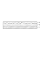
- FIG. 1 is a cross-sectional view showing a film of the present embodiment.
- the film of the present embodiment suppresses ash adhesion to the furnace and facilitates ash dropping.
- the film is composed of a base layer 12 formed on the surface of the base material 11 and a slidable material layer 13 formed as a top coat on the surface of the base layer 12.
- the base material 11 may be a steel material or a refractory material constituting a wall surface, or a carbon steel material or a stainless steel material constituting a heat transfer tube in a furnace such as a coal gasification furnace or a pulverized coal burning boiler.
- the refractory material include high alumina bricks and chromium / magnesia bricks.
- the base layer 12 is formed on the surface of the base material 11 with a predetermined thickness, and a surface having a large roughness is formed to fix the slidable material layer 13.
- the thickness of the base layer 12 may be 200 to 1000 ⁇ m.
- the surface roughness of the base layer 12 may be 1 to 20 ⁇ m in terms of arithmetic average roughness Ra.
- the base layer 12 may be an inorganic material such as metal or ceramics, and suppresses the enhancement of ash adhesion due to a corrosion reaction when the surface of the base material 11 is exposed to ash for a long time.
- the base layer 12 is made of a corrosion-resistant material, so that the corrosion resistance of the furnace can be improved. Examples of the corrosion resistant material include a high chromium alloy.
- the base layer 12 can also improve the fire resistance of a furnace by using a refractory material. Examples of the refractory material include castable refractories.
- the slidable material layer 13 is formed on the surface of the base layer 12 with a predetermined thickness by a slidable material.
- the thickness of the slidable material layer 13 may be 10 to 90 ⁇ m.
- the slidable material layer 13 includes oxide ceramics and a compound having a layered crystal structure. Examples of the oxide ceramics include oxides containing at least one of silicon, aluminum, chromium, manganese, and iron elements.
- the layered crystal structure refers to a crystal structure in which atoms or atomic groups are arranged in a plane to form a sheet structure, and the sheet structure repeats in a direction perpendicular to the plane. Among these, those belonging to the hexagonal system are also called graphite-type crystal structures, and have particularly high symmetry.
- Examples of the compound that can constitute the graphite type crystal structure include graphite, manganese sulfide, graphite fluoride, boron nitride, molybdenum disulfide, and tungsten disulfide.
- the slidable material layer 13 has the effect of lowering the frictional resistance of the surface of the layered crystal structure, so that the ash particles that have collided slip and the ashing ability of the attached ash is improved. Further, due to the durability of the oxide ceramics, the corrosion reaction between the ash and the base layer 12 in a high temperature environment is suppressed.
- Such a coating forms a base layer 12 on the surface of a base material 11 that forms a heat transfer tube and wall surface of a furnace of a coal gasification furnace or a pulverized coal-fired boiler, and is slidable as a top coat on the surface of the base layer 12. It is obtained by forming the material layer 13.
- the base layer 12 may be formed by spraying or applying an inorganic material.
- the slidable material layer 13 may be formed by applying or spraying a slurry of slidable material. When the slidable material contains silicone in addition to the oxide ceramics and the compound having a layered crystal structure, the coating property is improved.
- Silicone is a polymer having a main chain formed by alternately bonding silicon having an organic group and oxygen, and includes silicone resin, silicone rubber, silicone oil, silicone grease, and the like.
- the ratio of the oxide ceramics contained in the slidable material may be 1 to 30% by mass.
- the proportion of the compound having a layered crystal structure contained in the slidable material may be 10 to 30% by mass.
- the proportion of silicone contained in the slidable material may be 10 to 50% by mass.
- the coating may be applied to a furnace of a combustion apparatus or a reaction apparatus in addition to a furnace of a coal gasification furnace or a pulverized coal burning boiler.
- Example 1 a horizontal combustion furnace was used as the furnace, and an ash adhesion test was performed on the film of the present embodiment.
- the temperature inside the furnace in the combustion furnace was simulated, and the state of ash adhering to the probe surface on which the film exposed in the furnace was formed was observed.
- FIG. 2 is a cross-sectional view showing the structure of the combustion furnace used in the ash adhesion test.
- the combustion furnace 100 is configured in a horizontal type in which the combustion chamber 101 extends substantially horizontally along a flow path from the inlet 102 to the outlet 103.
- a plurality of segments are connected to each other by a flange 105 so as to be separable, and constitute a preheating part 121, a combustion part 122, and an ash adhesion part 123 along the flow path.
- the preheating unit 121 LPG and air are supplied from the inlet 102, air and oxygen gas are further supplied in the middle of the flow path, and the LPG burns.
- a throat 104 having a narrow flow path is formed at a portion where the preheating portion 121 transitions to the combustion portion 122.
- the throat 104 is supplied with pulverized coal stored in a tank 131 through a supply path 135 together with carrier gas air by a coal supplier 133.
- the quantity of heat of the supplied pulverized coal is 35 kW.
- the pulverized coal supplied from the throat 104 burns.
- generated by combustion of pulverized coal adheres to the probe 111 and wall surface which were installed in the combustion chamber 101.
- FIG. 2B is a cutaway perspective view showing the configuration of the segment 110 that constitutes the ash adhering portion 123 of the combustion chamber 101.
- the segments 110 are connected to each other by a flange 105, but in this perspective view, the flange 105 is omitted for simplicity.
- a probe port 113 for introducing the probe 111 therein, an observation port 115, a sampling port 117, and a thermocouple port 119 are formed in the cylindrical segment 110.
- the water-cooled probe 111 extends into the combustion chamber 101 and can be visually observed from the observation port 115.
- the diameter of the probe 111 is 31.8 mm.
- a sample of the combustion chamber 101 can be collected from the sampling port 117, and a thermocouple is inserted into the combustion chamber 101 from the thermocouple port 119.
- Reference numerals P1 to P6 in FIG. 2A indicate probes installed in the ash adhesion part 123 of the combustion chamber 101. These probes P1 to P6 are located at 836, 1200, 1562, 1924, 2297, and 2794 mm in the direction of the flow path with respect to the throat 104, respectively.
- the tests were conducted individually for slugging conditions and fouling conditions.
- the slagging condition is a condition in which ash melted in an environment where the gas temperature is equal to or higher than the softening temperature of ash adheres to the surface of the base material.
- a carbon steel material (SS400 steel) was used as the base material 11 assuming the inside wall of the furnace and the wall surface of the furnace outlet.
- the fouling conditions are conditions in which ash adheres to the surface of the base material in an environment where the gas temperature is equal to or lower than the softening temperature of ash.
- a stainless steel material (SUS304 steel) was used for the base material 11 assuming a heat transfer tube located at the rear of the furnace.
- the base layer 12 was a nickel-chromium alloy layer and was formed by an atmospheric plasma spraying method.
- the thickness of the base layer 12 was 450 ⁇ m.
- the surface roughness of the base layer 12 was 10 ⁇ m in terms of arithmetic average roughness Ra.
- the slidable material layer 13 is a fired film of a mixture containing oxide ceramics containing iron and manganese and boron nitride, 25% by mass of oxide ceramics, 15% by mass of boron nitride, and 40% by mass of silicone.
- a slurry of a mixture containing the remainder as an organic solvent was prepared, applied on the base layer 12, and then baked at 500 ° C. for 30 minutes to form a film.
- the thickness of the slidable material layer 13 was 30 ⁇ m.
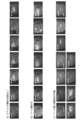
- FIG. 3 is a photograph showing the test results of the slagging conditions conducted in the combustion furnace of FIG.
- a when a carbon steel material without a coating (SS400 steel) is used for the probe 111, ash is removed from the probe 111 in 18 minutes, 40 minutes, and 53 minutes from the start of the test. It was.
- FIG. 3 (b) when carbon steel having only a base layer was used, ash was dropped from the probe 111 in 34 minutes from the start of the test.
- FIG.3 (c) when using what formed the membrane
- FIG. 4 is a photograph showing the test results of the fouling conditions performed in the combustion furnace of FIG.
- FIG. 4A when a stainless steel material (SUS304 steel) without a coating was used for the probe 111, ash was dropped from the probe 111 in 41 minutes from the start of the test.
- FIG. 4B when the stainless steel material having only the base layer formed thereon was used, ash was removed from the probe 111 in 50 minutes from the start of the test.
- FIG. 4 (c) when a stainless steel material having a base layer and a slidable material layer formed thereon is used, the probe 111 is removed 15 minutes, 29 minutes, and 59 minutes from the start of the test. Ashes dropped out.
- Example 1 in both cases of slagging conditions and fouling conditions, when the film is formed on the steel material, ash removal is promoted compared to the case without the film and the case where only the base layer is formed on the steel material. It was confirmed that Therefore, the effect which suppresses adhesion of ash was recognized by the film
- Example 2 tested the adhesion of ash to a furnace by immersing a test piece in simulated ash in an electric furnace and heating.
- the simulated ash and the test piece were heated in an electric furnace to a temperature equivalent to the surface temperature of the furnace, and the weight of the attached ash and the ratio of the ash removed by air blow were measured.
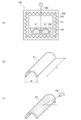
- FIG. 5 is a diagram for explaining the ash adhesion test.
- a heating chamber 151 is formed by the furnace material 152, and a heater 154 is disposed around the heating chamber 151 in the furnace material 152.
- a dish-like container 156 containing simulated ash 158 is placed on the bottom surface of the heating chamber 151.
- the temperature of the simulated ash 158 in the container 156 is monitored by a thermocouple 160.
- FIG.5 (b) is a perspective view which shows a test piece.
- the test piece 21 has a shape obtained by cutting a tube having a predetermined length along a cross section passing through its central axis, the width w is 31.8 mm, and the length l is 30 mm.
- FIG.5 (c) is a perspective view which shows the test piece 23 to which the simulated ash 158 adhered by the test. The simulated ash 158 is removed from the test piece 23 to which the simulated ash 158 is adhered by air blowing from a direction in which the angle ⁇ is 45 degrees from the cross section with respect to the central axis.
- the simulated ash 158 is composed of a powder of potassium sulfate (K 2 SO 4 ), sodium sulfate (Na 2 SO 4 ), and ferric oxide (Fe 2 O 3 ) at a ratio of 1: 1: 1.5. It was prepared by mixing at a molar ratio.
- FIG. 6 is a photograph showing the test results of the slagging conditions conducted in the electric furnace of FIG.
- the test piece 21 was made of a carbon steel material without a film, a carbon steel material having only a base layer formed, and a carbon steel material having a film made of a base layer and a slidable material layer, as in Example 1.
- Three types were prepared, and external photographs were taken at each stage before heating, after heating, and after air blowing. Comparing these photographs, the film formed on the carbon steel material at any stage after heating and after the air blow was compared with either the carbon steel material without the film or the carbon steel material formed with only the base layer. Also, it can be seen that the surface is smooth and the adhesion of the simulated ash 158 is suppressed.
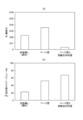
- FIG. 7 is a graph showing test results obtained by measuring the amount of ash and the like under slugging conditions performed in the electric furnace shown in FIG.
- FIG. 7A is a graph showing the amount of ash attached to the test piece.
- the amount of ash adhering to the test piece 21 is the largest when only a base layer is formed on a carbon steel material, followed by a carbon steel material without a coating, followed by a coating comprising a base layer and a slidable material layer on the carbon steel material. Was the least.
- FIG. 7 (b) is a graph showing the removal rate of ash adhering to the test piece by air blow.
- the removal rate of ash is the largest when carbon steel is formed with a coating consisting of a base layer and a slidable material layer, followed by carbon steel with only a base layer, followed by carbon steel without coating. It was the smallest.
- FIG. 8 is a photograph showing the test results of fouling conditions in the electric furnace of FIG.
- a stainless steel material without a film SUS304 steel
- a stainless steel material having only a base layer formed thereon SUS304 steel
- a stainless steel material having a base layer and a slidable material layer Three types were prepared, and appearance photographs were taken at each stage before heating, after heating, and after air blowing. Comparing these photographs, in both stages after heating and after air blowing, the one with the film formed on the stainless steel material is either the uncoated stainless steel material or the one with only the base layer formed on the stainless steel material. It can be seen that there is little adhesion of ash and the adhesion of simulated ash 158 is suppressed.
- FIG. 9 is a graph showing test results obtained by measuring the amount of ash and the like under the fouling conditions in the electric furnace of FIG. Fig.9 (a) is a graph which shows the adhesion amount of the ash to a test piece.
- the amount of ash adhering to the test piece 23 is the largest in stainless steel material without a film, followed by a base layer formed on a stainless steel material, followed by a film composed of a base layer and a slidable material layer on the stainless steel material. The least formed.
- FIG. 9 (b) is a graph showing the removal rate of the ash adhering to the test piece by air blow.
- the removal rate of ash is the largest when a coating made of a base layer and a slidable material layer is formed on a stainless steel material, followed by the formation of a base layer on a stainless steel material, followed by the stainless steel material without a coating. It was small.
- Example 2 in both cases of slagging conditions and fouling conditions, adhesion of ash is suppressed when a film is formed on a steel material, when there is no film, and when only a base layer is formed on a steel material In addition, it was confirmed that ash fallout was promoted. Therefore, the effect of suppressing the adhesion of ash to the film composed of the base layer and the slidable material layer of the present embodiment and facilitating the ash removal was recognized.
- the present disclosure can be applied to a furnace base material such as a coal gas furnace or a pulverized coal-fired boiler.
- Base material 12 Base layer 13 Sliding material layer 100 Combustion furnace
Landscapes
- Chemical & Material Sciences (AREA)
- Engineering & Computer Science (AREA)
- Ceramic Engineering (AREA)
- Organic Chemistry (AREA)
- Materials Engineering (AREA)
- Mechanical Engineering (AREA)
- Structural Engineering (AREA)
- General Engineering & Computer Science (AREA)
- Manufacturing & Machinery (AREA)
- Chemical Kinetics & Catalysis (AREA)
- Metallurgy (AREA)
- Physics & Mathematics (AREA)
- Thermal Sciences (AREA)
- Inorganic Chemistry (AREA)
- Oil, Petroleum & Natural Gas (AREA)
- Combustion & Propulsion (AREA)
- Coating By Spraying Or Casting (AREA)
- Other Surface Treatments For Metallic Materials (AREA)
Abstract
Description


12 ベース層
13 摺動性材料層
100 燃焼炉
Claims (7)
- 火炉の母材の表面に形成される皮膜であって、トップコートとして、酸化物セラミックスと、層状結晶構造を有する化合物とを含む摺動性材料層を有する皮膜。
- 前記摺動性材料層の下層に、耐腐食性材料又は耐火材で構成されたベース層を有する請求項1に記載の皮膜。
- 前記母材は、鋼材又は耐火材で構成されている請求項1又は2に記載の皮膜。
- 前記母材は、火炉の伝熱管又は壁面を構成する請求項1から3のいずれか一項に記載の皮膜。
- 請求項1から4のいずれか一項に記載の皮膜が形成された火炉。
- 請求項5に記載の火炉を含む石炭ガス化炉、微粉炭焚きボイラ、燃焼装置又は反応装置。
- 火炉の母材の表面に形成される皮膜の形成方法であって、
トップコートを形成する工程として、酸化物セラミックスと、層状結晶構造を有する化合物と、シリコーンとを含む摺動性材料のスラリーを塗布又はスプレーし、その後スラリーを焼成して成膜する工程
を含む皮膜の形成方法。
Priority Applications (6)
| Application Number | Priority Date | Filing Date | Title |
|---|---|---|---|
| CN201880090255.8A CN111788333A (zh) | 2018-03-02 | 2018-03-02 | 覆膜及其形成方法 |
| MYPI2020004453A MY200502A (en) | 2018-03-02 | 2018-03-02 | Coating and method for forming the same |
| PCT/JP2018/007942 WO2019167243A1 (ja) | 2018-03-02 | 2018-03-02 | 皮膜及びその形成方法 |
| AU2018411276A AU2018411276B2 (en) | 2018-03-02 | 2018-03-02 | Coating and method for forming the same |
| DE112018007208.8T DE112018007208T8 (de) | 2018-03-02 | 2018-03-02 | Beschichtung und verfahren zu deren herstellung |
| US17/009,315 US11504738B2 (en) | 2018-03-02 | 2020-09-01 | Coating and method for forming the same |
Applications Claiming Priority (1)
| Application Number | Priority Date | Filing Date | Title |
|---|---|---|---|
| PCT/JP2018/007942 WO2019167243A1 (ja) | 2018-03-02 | 2018-03-02 | 皮膜及びその形成方法 |
Related Child Applications (1)
| Application Number | Title | Priority Date | Filing Date |
|---|---|---|---|
| US17/009,315 Continuation US11504738B2 (en) | 2018-03-02 | 2020-09-01 | Coating and method for forming the same |
Publications (1)
| Publication Number | Publication Date |
|---|---|
| WO2019167243A1 true WO2019167243A1 (ja) | 2019-09-06 |
Family
ID=67805989
Family Applications (1)
| Application Number | Title | Priority Date | Filing Date |
|---|---|---|---|
| PCT/JP2018/007942 Ceased WO2019167243A1 (ja) | 2018-03-02 | 2018-03-02 | 皮膜及びその形成方法 |
Country Status (6)
| Country | Link |
|---|---|
| US (1) | US11504738B2 (ja) |
| CN (1) | CN111788333A (ja) |
| AU (1) | AU2018411276B2 (ja) |
| DE (1) | DE112018007208T8 (ja) |
| MY (1) | MY200502A (ja) |
| WO (1) | WO2019167243A1 (ja) |
Cited By (3)
| Publication number | Priority date | Publication date | Assignee | Title |
|---|---|---|---|---|
| JP2021139666A (ja) * | 2020-03-03 | 2021-09-16 | 株式会社Ihi | 付着力評価装置 |
| JP2023004980A (ja) * | 2021-06-25 | 2023-01-17 | パーカー加工株式会社 | 摺動部材 |
| WO2025192078A1 (ja) * | 2024-03-15 | 2025-09-18 | 株式会社Ihi | 皮膜、火炉、燃焼装置、反応装置、合金粉末及び皮膜の形成方法 |
Citations (3)
| Publication number | Priority date | Publication date | Assignee | Title |
|---|---|---|---|---|
| JPH06272817A (ja) * | 1993-03-24 | 1994-09-27 | Babcock Hitachi Kk | 微粉炭燃焼装置 |
| JP2004315309A (ja) * | 2003-04-17 | 2004-11-11 | Fuji Finetec Co Ltd | 耐火レンガ及び炉 |
| JP2007031565A (ja) * | 2005-07-27 | 2007-02-08 | Asahi Glass Co Ltd | 硬化性シリコーン樹脂組成物、それを用いた気密容器または電子部品の製造方法 |
Family Cites Families (23)
| Publication number | Priority date | Publication date | Assignee | Title |
|---|---|---|---|---|
| US4456635A (en) | 1982-12-30 | 1984-06-26 | Nalco Chemical Company | Intermittently applied coating of magnesium hydroxide to boiler tubes to prevent slag and deposit buildup |
| JP3166098B2 (ja) | 1994-10-14 | 2001-05-14 | 川崎製鉄株式会社 | 高温耐火材表面処理方法 |
| JP3332610B2 (ja) | 1994-10-21 | 2002-10-07 | 川崎製鉄株式会社 | コークス炉の補修方法 |
| JPH09143797A (ja) * | 1995-11-22 | 1997-06-03 | Mitsubishi Heavy Ind Ltd | 流体接触部材の耐摩耗被覆層及びその形成方法 |
| US5759663A (en) * | 1996-10-31 | 1998-06-02 | Thorpe Products Company | Hard-faced insulating refractory fiber linings |
| JP2981184B2 (ja) | 1997-02-21 | 1999-11-22 | トーカロ株式会社 | ボイラ伝熱管および管内面デポジット付着抑制効果に優れるボイラ伝熱管の製造方法 |
| JPH11351505A (ja) | 1998-06-08 | 1999-12-24 | Babcock Hitachi Kk | ボイラ伝熱管及びその製造方法 |
| JP2001049379A (ja) | 1999-08-12 | 2001-02-20 | Nkk Corp | 熱交換用伝熱管 |
| JP3675751B2 (ja) * | 2001-10-04 | 2005-07-27 | 財団法人北九州産業学術推進機構 | 炉材用耐火物および炉ならびに炉壁の表面処理方法 |
| JP2003120902A (ja) | 2001-10-09 | 2003-04-23 | Babcock Hitachi Kk | ごみ焼却炉発電ボイラ過熱器 |
| JP2003262490A (ja) | 2002-03-07 | 2003-09-19 | Kawasaki Heavy Ind Ltd | 伝熱管の付着灰除去方法及び付着灰の除去が容易な伝熱管 |
| JP2003287395A (ja) | 2002-03-28 | 2003-10-10 | Kyocera Corp | 熱交換器用セラミックス管およびその製造方法 |
| JP4464752B2 (ja) | 2003-10-21 | 2010-05-19 | 東北発電工業株式会社 | 付着防止方法 |
| JP4285755B2 (ja) | 2004-11-12 | 2009-06-24 | 三菱重工環境エンジニアリング株式会社 | クリンカ付着防止構造用のフェライト系耐熱合金 |
| JP4568094B2 (ja) | 2004-11-18 | 2010-10-27 | 株式会社東芝 | 遮熱コーティング部材およびその形成方法 |
| US20090110833A1 (en) * | 2007-10-31 | 2009-04-30 | Gala Industries, Inc. | Method for abrasion-resistant non-stick surface treatments for pelletization and drying process equipment components |
| JP2011169476A (ja) | 2010-02-16 | 2011-09-01 | Mitsubishi Heavy Ind Ltd | 付着灰除去方法 |
| JP2011169521A (ja) | 2010-02-18 | 2011-09-01 | Mitsubishi Heavy Ind Ltd | ボイラ装置およびボイラ装置の付着灰除去方法 |
| JP2012251228A (ja) | 2011-06-06 | 2012-12-20 | Babcock Hitachi Kk | 皮膜とその形成方法及び燃焼炉の炉内構造物 |
| AR100804A1 (es) | 2014-06-23 | 2016-11-02 | Nippon Steel & Sumitomo Metal Corp | Conexión roscada para tuberías de la industria del petróleo y composición para recubrimiento fotocurable |
| JP6550226B2 (ja) | 2014-10-31 | 2019-07-24 | トーカロ株式会社 | 溶射用粉末、溶射皮膜の製造方法、溶射皮膜、及びロール |
| JP6596214B2 (ja) | 2015-03-30 | 2019-10-23 | 株式会社フジミインコーポレーテッド | 溶射材料 |
| JP2016196820A (ja) | 2015-04-02 | 2016-11-24 | 株式会社Ihi | エンジン用圧縮機翼 |
-
2018
- 2018-03-02 DE DE112018007208.8T patent/DE112018007208T8/de active Active
- 2018-03-02 CN CN201880090255.8A patent/CN111788333A/zh active Pending
- 2018-03-02 WO PCT/JP2018/007942 patent/WO2019167243A1/ja not_active Ceased
- 2018-03-02 AU AU2018411276A patent/AU2018411276B2/en active Active
- 2018-03-02 MY MYPI2020004453A patent/MY200502A/en unknown
-
2020
- 2020-09-01 US US17/009,315 patent/US11504738B2/en active Active
Patent Citations (3)
| Publication number | Priority date | Publication date | Assignee | Title |
|---|---|---|---|---|
| JPH06272817A (ja) * | 1993-03-24 | 1994-09-27 | Babcock Hitachi Kk | 微粉炭燃焼装置 |
| JP2004315309A (ja) * | 2003-04-17 | 2004-11-11 | Fuji Finetec Co Ltd | 耐火レンガ及び炉 |
| JP2007031565A (ja) * | 2005-07-27 | 2007-02-08 | Asahi Glass Co Ltd | 硬化性シリコーン樹脂組成物、それを用いた気密容器または電子部品の製造方法 |
Cited By (4)
| Publication number | Priority date | Publication date | Assignee | Title |
|---|---|---|---|---|
| JP2021139666A (ja) * | 2020-03-03 | 2021-09-16 | 株式会社Ihi | 付着力評価装置 |
| JP7338512B2 (ja) | 2020-03-03 | 2023-09-05 | 株式会社Ihi | 付着力評価装置 |
| JP2023004980A (ja) * | 2021-06-25 | 2023-01-17 | パーカー加工株式会社 | 摺動部材 |
| WO2025192078A1 (ja) * | 2024-03-15 | 2025-09-18 | 株式会社Ihi | 皮膜、火炉、燃焼装置、反応装置、合金粉末及び皮膜の形成方法 |
Also Published As
| Publication number | Publication date |
|---|---|
| CN111788333A (zh) | 2020-10-16 |
| US20200391243A1 (en) | 2020-12-17 |
| AU2018411276B2 (en) | 2021-11-11 |
| DE112018007208T5 (de) | 2020-11-26 |
| MY200502A (en) | 2023-12-28 |
| AU2018411276A1 (en) | 2020-09-24 |
| DE112018007208T8 (de) | 2020-12-10 |
| US11504738B2 (en) | 2022-11-22 |
Similar Documents
| Publication | Publication Date | Title |
|---|---|---|
| US11504738B2 (en) | Coating and method for forming the same | |
| Syrodoy et al. | The efficiency of heat transfer through the ash deposits on the heat exchange surfaces by burning coal and coal-water fuels | |
| Regueiro et al. | Experimental study on the fouling behaviour of an underfeed fixed-bed biomass combustor | |
| JP6982391B2 (ja) | 皮膜の形成方法 | |
| JP5180291B2 (ja) | 希薄燃焼 | |
| Moloko et al. | Investigation of the mechanism for fireside corrosion in coal-fired boilers in South Africa | |
| TWI671365B (zh) | 皮膜及其形成方法 | |
| TWI749097B (zh) | 廢棄物焚化爐之鍋爐水管及其製造方法 | |
| Pîşă et al. | Experimental studies on the corrosion occurrence during biomass combustion process | |
| JPH11351505A (ja) | ボイラ伝熱管及びその製造方法 | |
| JP4464752B2 (ja) | 付着防止方法 | |
| Sato et al. | Effects and Countermeasures on Deposit Ash of Biomass Single Fired Power Plant | |
| Ryzhenkov et al. | Results of full-scale studies of corrosion and abrasive resistance of ion-plasma coating formed on samples of pipe heating surfaces of a biofuel boiler | |
| Barnes et al. | The slagging behaviour of three UK power station coals in an ash deposition rig | |
| WO2025192078A1 (ja) | 皮膜、火炉、燃焼装置、反応装置、合金粉末及び皮膜の形成方法 | |
| JPWO2002035151A1 (ja) | 耐高温腐食合金を用いた焼却またはガス化装置 | |
| JP2005146409A5 (ja) | ||
| Federer et al. | Analysis of candidate silicon carbide recuperator materials exposed to industrial furnace environments | |
| KR101803349B1 (ko) | 발전용 설비에서 사용되는 고수명, 내마모, 내부식, 난부착, 내화 세라믹 코팅 조성물 및 그를 적용한 미분탄용 유동층 보일러 및 그를 적용한 열회수용 보일러 튜브 | |
| JP7017290B2 (ja) | 耐腐食性の炉壁部材 | |
| Miller et al. | A CFD-Based Study of the Feasibility of Adapting an Erosion Burner Rig for Examining the Effect of CMAS Deposition Corrosion on Environmental Barrier Coatings | |
| CN108265293A (zh) | 带有金属陶瓷纳米涂层的热动力系统 | |
| Hurley et al. | Very-High-Temperature Materials and Heat Exchanger Testing in a Pilot-Scale Slagging Furnace | |
| Wnęk | ANALYSIS OF ECONOMIC EFFECTS AND POSSIBILITIES OF REDUCING CO 2 IN AN INDUSTRIAL THERMAL TREATMENT SYSTEM. | |
| Licata et al. | Design features for superheater corrosion control in municipal waste combustors |
Legal Events
| Date | Code | Title | Description |
|---|---|---|---|
| 121 | Ep: the epo has been informed by wipo that ep was designated in this application |
Ref document number: 18907645 Country of ref document: EP Kind code of ref document: A1 |
|
| ENP | Entry into the national phase |
Ref document number: 2018411276 Country of ref document: AU Date of ref document: 20180302 Kind code of ref document: A |
|
| 122 | Ep: pct application non-entry in european phase |
Ref document number: 18907645 Country of ref document: EP Kind code of ref document: A1 |
|
| NENP | Non-entry into the national phase |
Ref country code: JP |