WO2019163340A1 - Dispositif de refroidissement par rayonnement - Google Patents
Dispositif de refroidissement par rayonnement Download PDFInfo
- Publication number
- WO2019163340A1 WO2019163340A1 PCT/JP2019/001338 JP2019001338W WO2019163340A1 WO 2019163340 A1 WO2019163340 A1 WO 2019163340A1 JP 2019001338 W JP2019001338 W JP 2019001338W WO 2019163340 A1 WO2019163340 A1 WO 2019163340A1
- Authority
- WO
- WIPO (PCT)
- Prior art keywords
- layer
- silver
- light
- cooling device
- thickness
- Prior art date
Links
- 238000001816 cooling Methods 0.000 title claims abstract description 159
- 230000005855 radiation Effects 0.000 claims abstract description 158
- 229910052709 silver Inorganic materials 0.000 claims abstract description 123
- BQCADISMDOOEFD-UHFFFAOYSA-N Silver Chemical compound [Ag] BQCADISMDOOEFD-UHFFFAOYSA-N 0.000 claims abstract description 120
- 239000004332 silver Substances 0.000 claims abstract description 120
- 229910052782 aluminium Inorganic materials 0.000 claims abstract description 84
- XAGFODPZIPBFFR-UHFFFAOYSA-N aluminium Chemical compound [Al] XAGFODPZIPBFFR-UHFFFAOYSA-N 0.000 claims abstract description 82
- 238000005275 alloying Methods 0.000 claims abstract description 48
- 229910001316 Ag alloy Inorganic materials 0.000 claims abstract description 22
- 229910000838 Al alloy Inorganic materials 0.000 claims abstract description 19
- 150000004767 nitrides Chemical class 0.000 claims description 34
- 239000000758 substrate Substances 0.000 claims description 13
- 230000002265 prevention Effects 0.000 claims description 11
- 239000003963 antioxidant agent Substances 0.000 claims description 9
- 230000003078 antioxidant effect Effects 0.000 claims description 9
- 239000011521 glass Substances 0.000 claims description 9
- 239000005388 borosilicate glass Substances 0.000 claims description 6
- 239000005331 crown glasses (windows) Substances 0.000 claims description 6
- 229910045601 alloy Inorganic materials 0.000 abstract description 4
- 239000000956 alloy Substances 0.000 abstract description 4
- 230000000694 effects Effects 0.000 abstract description 4
- 238000010030 laminating Methods 0.000 abstract description 3
- 230000003287 optical effect Effects 0.000 abstract description 2
- 230000002035 prolonged effect Effects 0.000 abstract 1
- 239000010408 film Substances 0.000 description 145
- 239000013256 coordination polymer Substances 0.000 description 30
- 229910018072 Al 2 O 3 Inorganic materials 0.000 description 26
- 229910052760 oxygen Inorganic materials 0.000 description 23
- NDVLTYZPCACLMA-UHFFFAOYSA-N silver oxide Chemical class [O-2].[Ag+].[Ag+] NDVLTYZPCACLMA-UHFFFAOYSA-N 0.000 description 23
- 239000000463 material Substances 0.000 description 22
- 239000001301 oxygen Substances 0.000 description 22
- QVGXLLKOCUKJST-UHFFFAOYSA-N atomic oxygen Chemical compound [O] QVGXLLKOCUKJST-UHFFFAOYSA-N 0.000 description 20
- 229910052751 metal Inorganic materials 0.000 description 19
- 239000002184 metal Substances 0.000 description 19
- 238000010521 absorption reaction Methods 0.000 description 14
- 238000004544 sputter deposition Methods 0.000 description 14
- 238000004519 manufacturing process Methods 0.000 description 13
- 229910001923 silver oxide Inorganic materials 0.000 description 11
- 238000002834 transmittance Methods 0.000 description 11
- 230000031700 light absorption Effects 0.000 description 10
- 229910004298 SiO 2 Inorganic materials 0.000 description 9
- 230000008859 change Effects 0.000 description 9
- VYPSYNLAJGMNEJ-UHFFFAOYSA-N Silicium dioxide Chemical compound O=[Si]=O VYPSYNLAJGMNEJ-UHFFFAOYSA-N 0.000 description 8
- 238000006243 chemical reaction Methods 0.000 description 7
- TWNQGVIAIRXVLR-UHFFFAOYSA-N oxo(oxoalumanyloxy)alumane Chemical compound O=[Al]O[Al]=O TWNQGVIAIRXVLR-UHFFFAOYSA-N 0.000 description 7
- 238000007740 vapor deposition Methods 0.000 description 7
- 229910052581 Si3N4 Inorganic materials 0.000 description 6
- 238000000034 method Methods 0.000 description 6
- 230000035699 permeability Effects 0.000 description 6
- HQVNEWCFYHHQES-UHFFFAOYSA-N silicon nitride Chemical group N12[Si]34N5[Si]62N3[Si]51N64 HQVNEWCFYHHQES-UHFFFAOYSA-N 0.000 description 6
- 230000009471 action Effects 0.000 description 5
- 230000015572 biosynthetic process Effects 0.000 description 5
- KDLHZDBZIXYQEI-UHFFFAOYSA-N Palladium Chemical compound [Pd] KDLHZDBZIXYQEI-UHFFFAOYSA-N 0.000 description 4
- 229910010413 TiO 2 Inorganic materials 0.000 description 4
- 230000007423 decrease Effects 0.000 description 4
- 239000000203 mixture Substances 0.000 description 4
- 235000012239 silicon dioxide Nutrition 0.000 description 4
- 239000000377 silicon dioxide Substances 0.000 description 4
- DTPQZKZONQKKSU-UHFFFAOYSA-N silver azanide silver Chemical compound [NH2-].[Ag].[Ag].[Ag+] DTPQZKZONQKKSU-UHFFFAOYSA-N 0.000 description 4
- 238000001228 spectrum Methods 0.000 description 4
- RYGMFSIKBFXOCR-UHFFFAOYSA-N Copper Chemical compound [Cu] RYGMFSIKBFXOCR-UHFFFAOYSA-N 0.000 description 3
- 230000005540 biological transmission Effects 0.000 description 3
- 229910052802 copper Inorganic materials 0.000 description 3
- 239000010949 copper Substances 0.000 description 3
- 238000010438 heat treatment Methods 0.000 description 3
- 239000012466 permeate Substances 0.000 description 3
- FYYHWMGAXLPEAU-UHFFFAOYSA-N Magnesium Chemical compound [Mg] FYYHWMGAXLPEAU-UHFFFAOYSA-N 0.000 description 2
- PXHVJJICTQNCMI-UHFFFAOYSA-N Nickel Chemical compound [Ni] PXHVJJICTQNCMI-UHFFFAOYSA-N 0.000 description 2
- HCHKCACWOHOZIP-UHFFFAOYSA-N Zinc Chemical compound [Zn] HCHKCACWOHOZIP-UHFFFAOYSA-N 0.000 description 2
- GEIAQOFPUVMAGM-UHFFFAOYSA-N ZrO Inorganic materials [Zr]=O GEIAQOFPUVMAGM-UHFFFAOYSA-N 0.000 description 2
- 230000003064 anti-oxidating effect Effects 0.000 description 2
- 230000001747 exhibiting effect Effects 0.000 description 2
- 239000005357 flat glass Substances 0.000 description 2
- 239000007789 gas Substances 0.000 description 2
- 238000003475 lamination Methods 0.000 description 2
- 230000007774 longterm Effects 0.000 description 2
- 229910052749 magnesium Inorganic materials 0.000 description 2
- 239000011777 magnesium Substances 0.000 description 2
- 230000003647 oxidation Effects 0.000 description 2
- 238000007254 oxidation reaction Methods 0.000 description 2
- 229910052763 palladium Inorganic materials 0.000 description 2
- 230000009257 reactivity Effects 0.000 description 2
- 229910052710 silicon Inorganic materials 0.000 description 2
- 239000000126 substance Substances 0.000 description 2
- 239000013077 target material Substances 0.000 description 2
- 229910052725 zinc Inorganic materials 0.000 description 2
- 239000011701 zinc Substances 0.000 description 2
- 229910000975 Carbon steel Inorganic materials 0.000 description 1
- 229910005191 Ga 2 O 3 Inorganic materials 0.000 description 1
- 229910052688 Gadolinium Inorganic materials 0.000 description 1
- 229910005793 GeO 2 Inorganic materials 0.000 description 1
- 229910018068 Li 2 O Inorganic materials 0.000 description 1
- XUIMIQQOPSSXEZ-UHFFFAOYSA-N Silicon Chemical compound [Si] XUIMIQQOPSSXEZ-UHFFFAOYSA-N 0.000 description 1
- 229910006404 SnO 2 Inorganic materials 0.000 description 1
- 229910052771 Terbium Inorganic materials 0.000 description 1
- ATJFFYVFTNAWJD-UHFFFAOYSA-N Tin Chemical compound [Sn] ATJFFYVFTNAWJD-UHFFFAOYSA-N 0.000 description 1
- GWEVSGVZZGPLCZ-UHFFFAOYSA-N Titan oxide Chemical compound O=[Ti]=O GWEVSGVZZGPLCZ-UHFFFAOYSA-N 0.000 description 1
- RTAQQCXQSZGOHL-UHFFFAOYSA-N Titanium Chemical compound [Ti] RTAQQCXQSZGOHL-UHFFFAOYSA-N 0.000 description 1
- 230000032900 absorption of visible light Effects 0.000 description 1
- 230000008901 benefit Effects 0.000 description 1
- 229910052795 boron group element Inorganic materials 0.000 description 1
- 229910052800 carbon group element Inorganic materials 0.000 description 1
- 239000010962 carbon steel Substances 0.000 description 1
- 230000007797 corrosion Effects 0.000 description 1
- 238000005260 corrosion Methods 0.000 description 1
- 230000007547 defect Effects 0.000 description 1
- 230000006866 deterioration Effects 0.000 description 1
- 238000010586 diagram Methods 0.000 description 1
- 238000002845 discoloration Methods 0.000 description 1
- 238000009826 distribution Methods 0.000 description 1
- UIWYJDYFSGRHKR-UHFFFAOYSA-N gadolinium atom Chemical compound [Gd] UIWYJDYFSGRHKR-UHFFFAOYSA-N 0.000 description 1
- PCHJSUWPFVWCPO-UHFFFAOYSA-N gold Chemical compound [Au] PCHJSUWPFVWCPO-UHFFFAOYSA-N 0.000 description 1
- 229910052737 gold Inorganic materials 0.000 description 1
- 239000010931 gold Substances 0.000 description 1
- 229910021480 group 4 element Inorganic materials 0.000 description 1
- 229910021478 group 5 element Inorganic materials 0.000 description 1
- 230000006872 improvement Effects 0.000 description 1
- 229910052746 lanthanum Inorganic materials 0.000 description 1
- FZLIPJUXYLNCLC-UHFFFAOYSA-N lanthanum atom Chemical compound [La] FZLIPJUXYLNCLC-UHFFFAOYSA-N 0.000 description 1
- ORUIBWPALBXDOA-UHFFFAOYSA-L magnesium fluoride Chemical compound [F-].[F-].[Mg+2] ORUIBWPALBXDOA-UHFFFAOYSA-L 0.000 description 1
- WPBNNNQJVZRUHP-UHFFFAOYSA-L manganese(2+);methyl n-[[2-(methoxycarbonylcarbamothioylamino)phenyl]carbamothioyl]carbamate;n-[2-(sulfidocarbothioylamino)ethyl]carbamodithioate Chemical compound [Mn+2].[S-]C(=S)NCCNC([S-])=S.COC(=O)NC(=S)NC1=CC=CC=C1NC(=S)NC(=O)OC WPBNNNQJVZRUHP-UHFFFAOYSA-L 0.000 description 1
- 150000002739 metals Chemical class 0.000 description 1
- 229910052759 nickel Inorganic materials 0.000 description 1
- 229910000510 noble metal Inorganic materials 0.000 description 1
- 238000005546 reactive sputtering Methods 0.000 description 1
- 230000009467 reduction Effects 0.000 description 1
- 238000002310 reflectometry Methods 0.000 description 1
- 239000010703 silicon Substances 0.000 description 1
- VFWRGKJLLYDFBY-UHFFFAOYSA-N silver;hydrate Chemical compound O.[Ag].[Ag] VFWRGKJLLYDFBY-UHFFFAOYSA-N 0.000 description 1
- GZCRRIHWUXGPOV-UHFFFAOYSA-N terbium atom Chemical compound [Tb] GZCRRIHWUXGPOV-UHFFFAOYSA-N 0.000 description 1
- 239000010409 thin film Substances 0.000 description 1
- 239000011135 tin Substances 0.000 description 1
- 229910052718 tin Inorganic materials 0.000 description 1
- 229910052719 titanium Inorganic materials 0.000 description 1
- 239000010936 titanium Substances 0.000 description 1
- 229910052727 yttrium Inorganic materials 0.000 description 1
- VWQVUPCCIRVNHF-UHFFFAOYSA-N yttrium atom Chemical compound [Y] VWQVUPCCIRVNHF-UHFFFAOYSA-N 0.000 description 1
Images


Classifications
-
- F—MECHANICAL ENGINEERING; LIGHTING; HEATING; WEAPONS; BLASTING
- F28—HEAT EXCHANGE IN GENERAL
- F28F—DETAILS OF HEAT-EXCHANGE AND HEAT-TRANSFER APPARATUS, OF GENERAL APPLICATION
- F28F21/00—Constructions of heat-exchange apparatus characterised by the selection of particular materials
- F28F21/08—Constructions of heat-exchange apparatus characterised by the selection of particular materials of metal
- F28F21/081—Heat exchange elements made from metals or metal alloys
-
- F—MECHANICAL ENGINEERING; LIGHTING; HEATING; WEAPONS; BLASTING
- F28—HEAT EXCHANGE IN GENERAL
- F28F—DETAILS OF HEAT-EXCHANGE AND HEAT-TRANSFER APPARATUS, OF GENERAL APPLICATION
- F28F13/00—Arrangements for modifying heat-transfer, e.g. increasing, decreasing
- F28F13/18—Arrangements for modifying heat-transfer, e.g. increasing, decreasing by applying coatings, e.g. radiation-absorbing, radiation-reflecting; by surface treatment, e.g. polishing
-
- B—PERFORMING OPERATIONS; TRANSPORTING
- B32—LAYERED PRODUCTS
- B32B—LAYERED PRODUCTS, i.e. PRODUCTS BUILT-UP OF STRATA OF FLAT OR NON-FLAT, e.g. CELLULAR OR HONEYCOMB, FORM
- B32B15/00—Layered products comprising a layer of metal
- B32B15/04—Layered products comprising a layer of metal comprising metal as the main or only constituent of a layer, which is next to another layer of the same or of a different material
- B32B15/043—Layered products comprising a layer of metal comprising metal as the main or only constituent of a layer, which is next to another layer of the same or of a different material of metal
-
- B—PERFORMING OPERATIONS; TRANSPORTING
- B32—LAYERED PRODUCTS
- B32B—LAYERED PRODUCTS, i.e. PRODUCTS BUILT-UP OF STRATA OF FLAT OR NON-FLAT, e.g. CELLULAR OR HONEYCOMB, FORM
- B32B17/00—Layered products essentially comprising sheet glass, or glass, slag, or like fibres
- B32B17/06—Layered products essentially comprising sheet glass, or glass, slag, or like fibres comprising glass as the main or only constituent of a layer, next to another layer of a specific material
- B32B17/061—Layered products essentially comprising sheet glass, or glass, slag, or like fibres comprising glass as the main or only constituent of a layer, next to another layer of a specific material of metal
-
- G—PHYSICS
- G02—OPTICS
- G02B—OPTICAL ELEMENTS, SYSTEMS OR APPARATUS
- G02B5/00—Optical elements other than lenses
- G02B5/20—Filters
- G02B5/208—Filters for use with infrared or ultraviolet radiation, e.g. for separating visible light from infrared and/or ultraviolet radiation
-
- G—PHYSICS
- G02—OPTICS
- G02B—OPTICAL ELEMENTS, SYSTEMS OR APPARATUS
- G02B5/00—Optical elements other than lenses
- G02B5/20—Filters
- G02B5/26—Reflecting filters
Definitions
- the present invention provides a radiation in which an infrared radiation layer that radiates infrared light from a radiation surface and a light reflection layer that is positioned on the opposite side of the radiation surface on the side where the radiation surface is present are stacked.
- the present invention relates to a cooling device.
- Such a radiation cooling device transmits infrared light radiated from the radiation surface of the infrared radiation layer through an atmospheric window (for example, a window that transmits infrared light having a wavelength of 8 to 13 ⁇ m, etc.) to form a light reflection layer. It is used for cooling various cooling objects such as cooling the cooling object located on the side opposite to the side where the infrared radiation layer is present.
- an atmospheric window for example, a window that transmits infrared light having a wavelength of 8 to 13 ⁇ m, etc.
- the light reflecting layer reflects light (visible light, ultraviolet light, infrared light) transmitted through the infrared radiation layer and emits it from the radiation surface, thereby transmitting light (visible light, Ultraviolet light and infrared light) are projected onto the object to be cooled and the object to be cooled is prevented from being heated.
- the light reflection layer also has a function of reflecting infrared light radiated from the infrared radiation layer to the existence side of the light reflection layer toward the infrared radiation layer.
- the light reflection layer is provided to reflect light (visible light, ultraviolet light, infrared light) transmitted through the infrared radiation layer.
- the light reflection layer is a state in which a metal layer made of silver, a layer of titanium dioxide (TiO 2 ), and a layer of magnesium fluoride (MgF 2 ) are alternately arranged.
- a photoning band cap layer formed in a multilayer state in a state where the photoning band cap layer is positioned on the side close to the infrared radiation layer for example, Patent Document 1). reference.
- the light reflection layer is configured as a metal layer made of aluminum (for example, see Patent Document 2).
- a metal layer made of aluminum is used as a substrate, and an SiO layer and an MgO layer constituting an infrared radiation layer are laminated.
- the light reflecting layer is provided with the photoning band cap layer laminated in a multilayer state, so that there is a disadvantage that the manufacturing becomes complicated. Even if it is provided, the metal layer made of expensive silver cannot be made sufficiently thin, so there is a disadvantage that it is difficult to reduce the overall configuration.
- the light reflecting layer is configured as a metal layer made of aluminum
- the light reflecting layer is configured with inexpensive aluminum
- the overall configuration can be reduced. is there.
- the metal layer made of aluminum is easier to absorb light than silver
- the light transmitted through the infrared radiation layer is absorbed by the metal layer made of aluminum and the temperature rises due to the absorption of the light. Due to the metal layer heating the object to be cooled, there is a possibility that the object to be cooled cannot be appropriately cooled.
- the light reflecting layer is configured as a metal layer made of silver having a thickness of 100 nm or more
- the infrared radiation layer is transmitted.
- the cooling target can be cooled while suppressing the light from being projected onto the cooling target (see FIGS. 12 and 13), and the light reflecting layer is made of a metal made of silver having a thickness of 300 nm or more.
- the light to be transmitted through the infrared radiation layer can be appropriately suppressed from being projected onto the object to be cooled, and the object to be cooled can be appropriately cooled.
- the light reflection layer is configured as a metal layer made of silver having a thickness of 300 nm or more, the radiation cooling device becomes expensive. While suppressing, it was desired to cool the object to be cooled.
- the present invention has been made in view of the above circumstances, and its purpose is to appropriately cool the object to be cooled while reducing the cost of the light reflecting layer, and to provide a cooling action over a long period of time. It is in the point which provides the radiation cooling device which can demonstrate well.
- the radiant cooling device of the present invention includes an infrared radiation layer that radiates infrared light from a radiation surface, and a light reflection layer that is positioned on the opposite side of the radiation surface on the side where the radiation surface exists. It is provided and its characteristic configuration is
- the light reflecting layer includes a first layer made of silver or a silver alloy, a second layer made of aluminum or an aluminum alloy, and an alloying-preventing transparent layer for preventing alloying of silver and aluminum. In this case, the alloying-preventing transparent layer and the second layer are laminated in the order of being positioned on the side closer to the infrared radiation layer.
- the light reflecting layer is composed of a first layer made of silver or a silver alloy and a second layer made of aluminum or an aluminum alloy, and the first layer is close to an infrared radiation layer. It came to discover that it was possible to cool the object to be cooled while suppressing the amount of expensive silver or silver alloy used by forming a laminated state in a form positioned on the side.
- silver or a silver alloy can reflect visible light and infrared light efficiently, but tends to have a low reflectivity for ultraviolet light.
- aluminum or aluminum alloy cannot reflect visible light or infrared light more efficiently than silver or silver alloy, but tends to reflect ultraviolet light efficiently.
- aluminum or aluminum alloy tends to absorb visible light and infrared light more easily than silver or silver alloy.
- the first layer made of silver or a silver alloy and the second layer made of aluminum or an aluminum alloy in a state in which the first layer is positioned so as to be positioned closer to the infrared radiation layer
- the second layer suppresses absorption of visible light or infrared light, and even if the thickness of the first layer is reduced, the first layer
- light visible light, ultraviolet light, infrared light
- the 1st layer which consists of silver or a silver alloy can be made thin, the cost reduction of a light reflection layer can be aimed at.
- an alloying prevention transparent layer for preventing alloying of silver and aluminum is provided between the first layer and the second layer, it is possible to suppress alloying of silver and aluminum. While avoiding light absorption of the light reflecting layer, the state in which the light reflecting layer appropriately reflects light can be maintained for a long period of time, and the cooling effect can be exhibited well over a long period of time.
- the alloying of silver and aluminum gradually progresses, and the reflectance of sunlight in the light reflecting layer is increased.
- the solar absorption is expected to increase. It suppresses alloying of silver and aluminum.
- the object to be cooled can be appropriately cooled while the cost of the light reflecting layer is reduced, and the cooling effect can be exhibited well over a long period of time.
- a further characteristic configuration of the radiant cooling device of the present invention is that the thickness of the first layer is larger than 3.3 nm and not larger than 100 nm.
- the infrared radiation layer is transmitted due to the presence of the second layer. It was found that the object to be cooled can be cooled by appropriately reflecting light (visible light, ultraviolet light, infrared light).
- the thickness of the first layer made of silver or a silver alloy is set to a thin thickness greater than 3.3 nm and less than or equal to 100 nm, the light reflection layer can be sufficiently inexpensive, The object to be cooled can be cooled.
- the thickness of the first layer made of silver or a silver alloy is preferably larger than 3.3 nm and 100 nm or less, preferably 30 nm or more, so that the cooling target can be appropriately set. It can be cooled.
- the object to be cooled can be cooled while sufficiently reducing the cost of the light reflecting layer.
- a further characteristic configuration of the radiation cooling device of the present invention is that the thickness of the first layer is not less than 50 nm and not more than 100 nm.
- the thickness of the first layer made of silver or a silver alloy is in the range of 50 nm to 100 nm, the light (mainly visible light, infrared light) reflecting action by the first layer is appropriately exhibited.
- the presence of the second layer allows the light (visible light, ultraviolet light, infrared light) transmitted through the infrared radiation layer to be appropriately reflected.
- the light reflective layer is made of silver having a thickness of 300 nm or more. It came to discover that the object to be cooled can be cooled with the same capacity as that of the metal layer.
- a further characteristic configuration of the radiant cooling device of the present invention is that the thickness of the second layer is 10 nm or more.
- the second layer reflects ultraviolet light if the thickness of the second layer made of aluminum or aluminum alloy is 10 nm or more. It came to find that the light (visible light, ultraviolet light, infrared light) which permeate
- the thickness of the second layer made of aluminum or aluminum alloy may be 10 nm or more, but in order to suppress the amount of aluminum or aluminum alloy used, it is necessary to avoid making it thicker than necessary.
- the radiation cooling device of the present invention it is possible to reflect the light transmitted through the infrared radiation layer while appropriately exhibiting the action of reflecting the ultraviolet light.
- a further characteristic configuration of the radiation cooling device of the present invention is that the infrared radiation layer is made of any one of alkali-free glass, crown glass, and borosilicate glass.
- alkali-free glass, crown glass, and borosilicate glass are relatively inexpensive, but have excellent transmittance of sunlight (visible light, ultraviolet light, near infrared light) (for example, about 80%). Because it does not absorb sunlight, it emits infrared light having a wavelength equivalent to an atmospheric window (for example, a window that transmits infrared light having a wavelength of 8 to 13 ⁇ m). It has the property of high radiation intensity.
- the infrared radiation layer with any one of alkali-free glass, crown glass, and borosilicate glass, a radiation cooling device with a high cooling capacity can be achieved while reducing the overall configuration. Can be obtained.
- the cooling capacity can be improved while the overall configuration is reduced.
- a further characteristic configuration of the radiation cooling device of the present invention is that the first layer, the alloying-preventing transparent layer, and the second layer are laminated using the infrared radiation layer as a substrate.
- the overall configuration can be simplified and the overall configuration can be reduced in thickness.
- the first layer, the anti-alloying transparent layer and the second layer are laminated with the infrared radiation layer as the substrate, if the first layer, the anti-alloying transparent layer and the second layer are thin, for example, The first layer, the alloying-preventing transparent layer, and the second layer are sequentially laminated by sputtering or the like.
- the second layer, the alloying-preventing transparent layer, and the first layer are sequentially laminated on the lamination substrate by sputtering or the like, and then the presence of the second layer of the first layer.
- a separately prepared infrared radiation layer is placed on the side opposite to the side and laminated, or the part opposite to the side where the first alloying prevention transparent layer is present is sputtered, etc.
- it is not necessary to provide a substrate for stacking so that the overall configuration can be simplified and the overall configuration can be made thinner.
- the overall configuration can be simplified and the overall configuration can be made thinner.
- a further characteristic configuration of the radiation cooling device of the present invention is that an adhesion layer is laminated between the infrared radiation layer and the first layer.
- the adhesion layer is laminated between the infrared radiation layer and the first layer of the light reflection layer, the first layer of the light reflection layer is in contact with the infrared radiation layer due to a temperature change or the like. Since the occurrence of damage such as peeling can be suppressed, durability can be improved.
- a further characteristic configuration of the radiant cooling device of the present invention is that an antioxidant layer is laminated on the second layer opposite to the side where the alloying-preventing transparent layer is present.
- the antioxidant layer is laminated on the opposite side of the second layer made of aluminum or aluminum alloy from the side where the anti-alloying transparent layer is present, the second layer is oxidized even if the second layer is thinned. Therefore, since it can suppress that it deteriorates, durability can be improved.
- the radiant cooling device of the present invention it is possible to suppress the deterioration of the second layer made of aluminum or aluminum alloy and improve the durability.
- a further characteristic configuration of the radiation cooling device of the present invention is that the alloying-preventing transparent layer is a transparent nitride film.
- the transparent nitride film As the alloying-preventing transparent layer, it is possible to appropriately suppress the first layer of silver or silver alloy and the second layer of aluminum or aluminum alloy from being alloyed.
- Si 3 N 4 and AlN can be given as specific examples of the transparent nitride film.
- the transparent nitride film has an advantage that it is easy to improve productivity because the first layer of silver or silver alloy is not discolored when the film is formed by sputtering or vapor deposition.
- a further characteristic configuration of the radiation cooling device of the present invention is that the alloying-preventing transparent layer is a transparent oxide film.
- a transparent oxide film as the alloying-preventing transparent layer, it is possible to appropriately suppress the first layer of silver or silver alloy and the second layer of aluminum or aluminum alloy from being alloyed.
- many transparent oxide films can be applied.
- Al 2 O 3 , SiO 2 , TiO 2 , ZrO 2 , HfO 2 , and Nb 2 that can be easily formed by vapor deposition, sputtering, or the like. Examples thereof include O 5 and Ta 2 O 5 .
- a further characteristic configuration of the radiant cooling device of the present invention is that the alloying-preventing transparent layer has a thickness in which any one of wavelengths of 400 nm or less is a resonance wavelength.
- the thickness of the anti-alloying transparent layer is set so that any one of the wavelengths of 400 nm or less is a resonance wavelength. The light absorption amount as a whole reflection layer is suppressed.
- the sunlight spectrum is generally in the wavelength range of 300 to 4000 nm, and the sunlight intensity (light energy) longer than 400 nm is strong, but the light in the ultraviolet region of 300 to 400 nm is Because it hits the tail, it is not energetic. Therefore, even if the alloying-preventing transparent layer absorbs light, the light absorption amount of the entire light reflection layer can be suppressed by absorbing light on the short wavelength side of 400 nm or less.
- the light absorption amount of the entire light reflection layer can be suppressed.
- the alloying-preventing transparent layer has a thickness with any one of wavelengths of 300 nm or less as a resonance wavelength.
- the anti-alloying transparent layer absorbs light, but the thickness of the anti-alloying transparent layer is set to a thickness having a resonance wavelength of any one of wavelengths of 300 nm or less.
- the light absorption amount as a whole reflection layer is appropriately suppressed.
- the sunlight spectrum is generally in the wavelength range of 300 to 4000 nm, and the sunlight intensity (light energy) longer than 400 nm is strong, but the light in the ultraviolet region of 300 to 400 nm is Since it hits the tail, it is not large in terms of energy, and further, in terms of energy at the shorter wavelength side, it becomes smaller in terms of energy. Therefore, even if the alloying-preventing transparent layer absorbs light, it is possible to appropriately suppress the light absorption amount of the entire light reflection layer by absorbing light on the short wavelength side of 300 nm or less.
- the radiation cooling device of the present invention it is possible to appropriately suppress the light absorption amount of the entire light reflection layer.
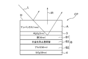
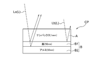
- the radiation cooling device CP includes an infrared radiation layer A that radiates infrared light IR from the radiation surface H, and a side opposite to the side where the radiation surface H is present in the infrared radiation layer A.
- the light reflection layer B to be positioned is provided in a laminated state.
- the light reflecting layer B includes a first layer B1 made of silver or a silver alloy and a second layer B2 made of aluminum (abbreviated as “aluminum” in the following description) or an aluminum alloy (abbreviated as “aluminum alloy” in the following description).
- an alloying-preventing transparent layer B3 for preventing alloying of silver and aluminum are positioned on the side closer to the infrared radiation layer A in the order of the first layer B1, the alloying-preventing transparent layer B3, and the second layer B2. It is comprised in the state laminated
- the thickness (film thickness) of the first layer B1 is configured to be larger than 3.3 nm and 100 nm or less, and preferably the thickness (film thickness) of the first layer B1 is configured to be 50 nm or more and 100 nm or less. Has been.
- the thickness (film thickness) of the second layer B2 is configured to be 10 nm or more.
- the “silver alloy” an alloy in which any of copper, palladium, gold, zinc, tin, magnesium, nickel and titanium is added to silver, for example, about 0.4 to 4.5 mass% is used. Can do.
- APC-TR made by Furuya Metal
- the first layer B1 is made of silver.
- the “aluminum alloy” an alloy obtained by adding copper, manganese, silicon, magnesium, zinc, carbon steel for mechanical structure, yttrium, lanthanum, gadolinium, and terbium to aluminum can be used. In the following description, it is assumed that the second layer B2 is made of aluminum.
- the alloying-preventing transparent layer B3 is composed of a transparent nitride film or a transparent oxide film.
- the transparent nitride film include Si 3 N 4 and AlN.
- the transparent oxide film include Al 2 O 3 , SiO 2 , TiO 2 , ZrO 2 , HfO 2 , Nb 2 O 5 , Ta 2 O 5 , and other oxides that can be easily formed by vapor deposition or sputtering. The details will be described later.
- the thickness of the alloying-preventing transparent layer B3 is such that any one of the wavelengths of 400 nm or less is a resonance wavelength, and preferably any one of the wavelengths of 300 nm or less is the resonance wavelength. The details will be described later.
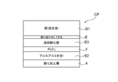
- the radiant cooling device CP is configured by laminating the first layer B1, the alloying-preventing transparent layer B3, and the second layer B2 using the infrared radiation layer A as a substrate. Specifically, the adhesion layer 3 is laminated between the infrared radiation layer A as the substrate and the first layer B1, and the opposite side of the second layer B2 from the existence side of the anti-alloying transparent layer B3. In addition, an antioxidant layer 4 is laminated.
- the radiant cooling device CP sequentially forms the adhesion layer 3, the first layer B1, the alloying prevention transparent layer B3, the second layer B2, and the antioxidant layer 4 by, for example, sputtering using the infrared radiation layer A as a substrate. It is comprised in the form to do.
- the adhesion layer 3 is configured to form aluminum oxide (Al 2 O 3 ) to a thickness of 20 to 100 nm.
- the antioxidant layer 4 is configured to form silicon dioxide (SiO 2 ) or aluminum oxide (Al 2 O 3 ) to a thickness of 10 to several 100 nm. In the following description, it is assumed that silicon dioxide (SiO 2 ) is formed.
- the infrared radiation layer A is made of any one of alkali-free glass, crown glass, and borosilicate glass (white plate glass).
- alkali-free glass for example, OA10G (manufactured by Nippon Electric Glass) can be used
- crown glass for example, B270 (registered trademark, the same shall apply hereinafter)
- borosilicate glass for example, Tempax (registered trademark, hereinafter the same) can be used.
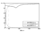
- “OA10G”, “B270”, and “Tempax” have high transmittance with respect to light having a wavelength corresponding to sunlight as shown in FIG. 8, and also have high atmospheric transmittance as shown in FIG. The emissivity of the wavelength corresponding to the wavelength range (so-called atmospheric window) is high.
- FIG. 8 exemplifies “Tempax” as a representative, but “OA10G”, “B270”, etc. of white plate glass are the same. In the following description, it is assumed that the infrared radiation layer A is formed of “Tempax”.
- the radiant cooling device CP reflects a part of the light L incident on the radiant cooling device CP (for example, a part of sunlight) on the radiation surface H of the infrared radiation layer A.
- the light (ultraviolet light, etc.) transmitted through the infrared radiation layer A among the light L incident on the radiation cooling device CP is reflected by the light reflection layer B.
- heat input to the radiation cooling device CP from the cooling object D located on the side opposite to the side where the light reflection layer B is present in the antioxidant layer 4 (for example, heat input from the cooling object D by heat conduction) is converted into red.
- the cooling target D is cooled by being converted into infrared light IR by the outer radiation layer A and radiating.
- light means an electromagnetic wave having a wavelength of 10 nm to 20000 nm. That is, the light L includes ultraviolet light, infrared light IR, and visible light.
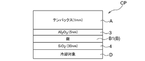
- the radiation cooling device CP is formed by forming an infrared radiation layer A with a Tempax having a thickness of 1 mm, a first layer B1 of the light reflection layer B having a thickness of 50 nm, and reflecting light.
- the second layer B2 of the layer B is made of aluminum with a film thickness of 50 nm
- the adhesion layer 3 is formed with aluminum oxide (Al 2 O 3 ) with a film thickness of 5 nm
- silicon dioxide (SiO 2 ) with a film thickness of 30 nm is formed.
- the oxidation preventing layer 4 is formed and the alloying prevention transparent layer B3 of the light reflecting layer B is composed of Si 3 N 4 as a transparent nitride film or Al 2 O 3 as a transparent oxide film
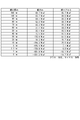
- the cooling capacity of the radiant cooling device CP was calculated while changing the thickness of Si 3 N 4 as the transparent nitride film and Al 2 O 3 as the transparent oxide film, and the results shown in the tables of FIGS. 3 and 4 were obtained. became.
- the tables in FIG. 3 and FIG. 4 were calculated using a clear day in Osaka in late August as a model. That is, the solar energy is 1000 W / m 2 , the outside air temperature is 30 ° C., and the atmospheric radiation energy is 387 W / m 2 , which is calculated in late August as a model. This is calculated assuming that the temperature of the surface of the layer 4 on the side opposite to the side where the light reflecting layer B is present: hereinafter referred to as the cooling surface temperature) is 30 ° C.
- the thickness (film thickness) of Si 3 N 4 is best at 34 nm or less, and may be 47 nm or less. The reason will be described later.
- the thickness (film thickness) of Al 2 O 3 is best at 44 nm or less, and may be 60 nm or less. The reason will be described later.
- the table in FIG. 7 was calculated using a clear day in Osaka in late August as a model. That is, the solar energy is 1000 W / m 2 , the outside air temperature is 30 ° C., and the atmospheric radiation energy is 387 W / m 2 , which is calculated in late August as a model. The temperature was calculated as 30 ° C. Note that the cooling capacity in FIG. 7 is calculated assuming that the alloying-preventing transparent layer B3 does not exist.
- the radiation cooling device CP when the light reflection layer B is composed only of the first layer B1 (see FIG. 5), when the thickness of the silver forming the first layer B1 is 30 nm or less, the radiation cooling device CP However, when the light reflecting layer B is composed of the first layer B1 and the second layer B2 (see FIG. 6), if the thickness of silver is larger than 3.3 nm, The radiant cooling device CP has a cooling capacity.
- the light reflecting layer B is composed of the first layer B1 and the second layer B2 (see FIG. 6)
- the cooling capacity of the radiation cooling device CP is light reflecting.
- the layer B is composed of only the first layer B1 (see FIG. 5)
- the same ability is obtained when the silver thickness is 300 nm.
- the thickness of the Tempax constituting the infrared radiation layer A needs to be 10 ⁇ m or more and 10 cm or less, preferably 20 ⁇ m or more and 10 cm or less, more preferably 100 ⁇ m or more and 1 cm or less. That is, the infrared radiation layer A exhibits a large thermal radiation in the infrared region having a wavelength of 8 ⁇ m or more and 14 ⁇ m or less, and the thermal radiation is absorbed by each of the infrared radiation layer A and the light reflection layer B. By making it larger than sunlight and the thermal radiation of the atmosphere, it is possible to configure a radiant cooling device CP that exhibits a radiative cooling action in which the temperature is lower than the surrounding atmosphere regardless of day or night.
- the thickness must be 10 ⁇ m or more and 10 cm or less, preferably 20 ⁇ m or more and 10 cm or less, more preferably 100 ⁇ m or more and 1 cm or less are preferable.
- the cooling capacity of the radiation cooling device CP is improved, but in a state where silver and aluminum are kept in contact with each other.
- the alloying of silver and aluminum progresses, the reflectance of sunlight decreases, and the absorption of sunlight increases. Therefore, between the first layer B1 and the second layer B2 By positioning the alloying preventing transparent layer B3, alloying of silver and aluminum is suppressed.
- the anti-alloying transparent layer B3 When the anti-alloying transparent layer B3 is positioned between the first layer B1 and the second layer B2, the reflectance of sunlight in the light reflecting layer B is slightly lowered and the absorption of sunlight is slightly increased. Therefore, as shown in FIGS. 3 and 4, when the thickness of Si 3 N 4 as a transparent nitride film and Al 2 O 3 as a transparent oxide film is set to 0 nm, that is, an alloying-preventing transparent layer Compared to the case without B3, the cooling capacity of the radiation cooling device CP is slightly reduced, but the alloying of silver and aluminum is suppressed, and the reflection performance of the light reflection layer B is maintained over a long period of time. It will be possible.
- the light reflection layer B of the radiation cooling device CP is provided with the first layer B1 and the second layer B2.
- the light reflection layer B of the radiation cooling device CP is composed only of the first layer B1 made of silver having a thickness of 50 nm, as shown in FIG. The light passes through the 50 nm silver constituting the first layer B1, and the transmitted light is irradiated to the cooling object D.
- the cooling object D is configured as a light absorption layer or a heat exchanger in order to efficiently release the heat of the object to be cooled, but the thickness (thickness) of the silver constituting the first layer B1 is reduced. Then, since the transmitted light warms the cooling object D, the radiation cooling capacity (radiation cooling performance) is weakened.
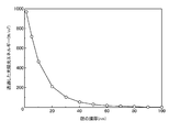
- FIG. 13 shows the film thickness (thickness) of silver and the energy of sunlight (W / m) in the radiation cooling device CP (see FIG. 10) in which the light reflecting layer B is composed of the first layer B1 made of silver. 2 ).
- the radiation cooling capacity of the conventional radiant cooling device CP in which the film thickness (thickness) of the silver constituting the first layer B1 is 300 nm is as follows: summer in Japan, altitude 0m, outside temperature 30 ° C It is approximately 70 W / m 2 , depending on the humidity and the air quality during the south-west.
- the film thickness (thickness) of the silver constituting the first layer B1 is 100 nm
- the energy of transmitted sunlight becomes about 7 W / m 2
- this transmitted light heats the cooling target D.
- the cooling capacity of the radiation cooling device CP is reduced by about 10%.
- the film thickness (thickness) of the silver constituting the first layer B1 is 50 nm
- the energy of transmitted sunlight becomes about 70 W / m 2
- the transmitted light is radiated by heating the cooling object D.
- the radiation cooling capacity of the cooling device CP is greatly reduced.
- the film thickness (thickness) of the silver constituting the first layer B1 is reduced.
- the problem that occurred was explained. That is, in the case where the light reflecting layer B is constituted by only the first layer B1, the film thickness (thickness) of the silver constituting the first layer B1 cannot be sufficiently reduced.
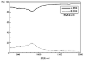
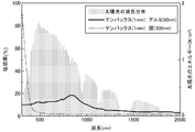
- film thickness (thickness) As shown in FIG. 16, if aluminum has a film thickness (thickness) of 25 nm or more, it can shield sunlight transmission accurately. However, as shown in FIG. 15, aluminum tends to have a higher absorption rate of sunlight, and as shown in FIG. 17, aluminum (film thickness 50 nm) emits sunlight more than silver (film thickness 300 nm). It absorbs a lot.
- the problem in the case where the light reflecting layer B is constituted only by the second layer B2 has been described with reference to FIGS. That is, it can be seen that when the light reflection layer B is configured only by the second layer B2, the radiation cooling capacity of the radiation cooling device CP cannot be made sufficient.
- the present inventor has found that if the light reflection layer B of the radiation cooling device CP is constituted by the first layer B1 and the second layer B2, the film thickness (thickness) of the silver constituting the first layer B1. It has been found that the radiation cooling capacity can be made sufficient while the thickness is reduced.
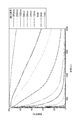
- the transmittance of silver constituting the first layer B1 increases as the wavelength decreases, and increases as the film thickness (thickness) decreases.
- the reflectance of silver constituting the first layer B1 is larger on the long wavelength side, smaller on the shorter wavelength side, and smaller as the film thickness (thickness) becomes thinner.
- the aluminum of the second layer B2 is provided with a large reflectance enough to shield sunlight transmission as long as it has a film thickness (thickness) of 25 nm or more.
- the reflectance tends to be smaller than that of silver.
- crossing wavelength the wavelength at which the reflectance of silver and the reflectance of aluminum intersect (hereinafter, abbreviated as “crossing wavelength”) varies depending on the film thickness (thickness) of silver.
- FIG. 22 illustrates cross wavelengths when the film thickness (thickness) of aluminum is changed when the film thickness (thickness) of aluminum is 200 nm.
- the film thickness (thickness) of silver constituting the first layer B1 is 50 nm.
- the cross wavelength is 450 nm, and in the light La on the shorter wavelength side than 450 nm, aluminum is more silver than silver.
- the reflectance of silver is higher than that of aluminum in light Lb on the longer wavelength side.
- light having a wavelength of 450 nm or less, which is an intersecting wavelength easily transmits silver, and thus the transmitted light is irradiated to the aluminum of the second layer B2.
- the light La having a wavelength shorter than 450 nm is reflected by the first layer B1 partially formed of silver, and the light transmitted through the first layer B1 is formed of aluminum. It is reflected by the second layer B2. Further, the light Lb having a wavelength longer than 450 nm is mainly reflected by the first layer B1.
- the light reflecting layer B is composed of the first layer B1 and the second layer B2
- the film thickness (thickness) of the aluminum constituting the second layer B2 is greater than 10 nm. Since it does not transmit, the film thickness (thickness) of the second layer B2 is 10 nm or more.
- the thickness (thickness) of the aluminum constituting the second layer B2 is increased to 50 nm or more. That is, aluminum is oxidized to form a passive state, but the durability increases as the layer capable of forming the passive state becomes thicker.
- the film thickness (thickness) of the silver of the first layer B1 is 50 nm
- the aluminum of B2 By reflecting with the aluminum of B2, the light transmitted through the infrared radiation layer A can be efficiently reflected.
- the light reflecting layer B is composed of the first layer B1 and the second layer B2
- the light having a wavelength longer than the crossing wavelength is reflected mainly by the silver of the first layer B1, and the silver is reflected.
- the light transmitted through the infrared radiation layer A can be efficiently reflected.
- the film thickness (thickness) of the first layer B1 is 100 nm or less and 50 nm or more, The reflectance of sunlight can be sufficiently improved.
- the radiation cooling device CP will produce a radiant cooling capability (radiant cooling performance).
- the radiation cooling capacity (radiation cooling performance) of the radiation cooling device CP is such that the light reflection layer B is composed of only the first layer B1 ( In FIG. 2), the same ability is obtained when the silver thickness is 300 nm.
- the light reflection layer B of the radiation cooling device of the present invention is made of a noble metal by reflecting light in the visible light region from the ultraviolet light that passes through the silver of the first layer B1 with the aluminum of the second layer B2. It reduces the amount of silver used. For this reason, the light transmitted through the silver of the first layer B1 needs to be transmitted as much as possible through the transparent nitride film and the transparent oxide film constituting the alloying-preventing transparent layer B3.
- the transparent nitride film and transparent oxide film constituting the alloying prevention transparent layer B3 need to be transparent in the ultraviolet to visible light region, but what kind of transparent nitride film and transparent oxide film are suitable?
- narrow down from the viewpoint of chemical reactivity it is preferable to screen with reference to the standard production Gibbs energy.
- the reaction of the following formula (1) in which the metal A and oxygen react proceeds in the direction in which the standard production Gibbs energy is small.
- the standard production Gibbs energy is smaller in the reaction of the following formula (2) than the reaction of the above formula (1).
- the oxide film semi-permanently highly transparent select a material with a standard Gibbs energy of transparent nitride film and transparent oxide film that is smaller than that of silver or aluminum as the material for transparent nitride film or transparent oxide film. It is important to do.
- the material of the transparent oxide film there is no problem even if a material higher than the standard generation energy of aluminum is selected because of the low oxygen diffusibility of aluminum.
- a material higher than the standard generation energy of aluminum is selected because of the low oxygen diffusibility of aluminum.
- a transparent nitride film a material whose standard generation Gibbs energy is equal to or less than silver and aluminum may be selected. That is, since Ag 3 N (+315 kJ / mol) and AlN ( ⁇ 287 kJ / mol), a material smaller than ⁇ 287 kJ / mol of Al is preferable, and a material transparent in the ultraviolet to visible region is desired. Specific examples of materials that satisfy such conditions include Si 3 N 4 ( ⁇ 676 kJ / mol) and AlN ( ⁇ 287 kJ / mol).
- a material whose standard generation Gibbs energy change is equal to or less than silver may be selected. That is, since it is Ag 2 O ( ⁇ 11 kJ / mol), it is preferable to select a material whose standard production Gibbs energy is smaller than ⁇ 11 kJ / mol.
- the transparent oxide film there is no problem even if a material larger than the standard production Gibbs energy ( ⁇ 1582 kJ / mol) of the aluminum oxide Al 2 O 3 is used. The reason is that Al 2 O 3 is a material having an extremely low oxygen diffusibility. A specific example will be described.
- Group 1 element oxides Li 2 O ( ⁇ 561 kJ / mol), Na 2 O ( ⁇ 375 kJ / mol), K 2 O ( ⁇ 320 kJ / mol)
- Group 2 element oxides BeO (-580 kJ / mol), MgO (-569 kJ / mol), CaO (-604 kJ / mol), SrO (-592 kJ / mol), BaO (-520 kJ / mol)
- Group 4 element oxides TiO 2 ( ⁇ 884 kJ / mol), ZrO 2 ( ⁇ 1042 kJ / mol), HfO 2 ( ⁇ 1088 kJ / mol)
- Group 5 element oxides Nb 2 O 5 ( ⁇ 1766 kJ / mol), Ta 2 O 5 ( ⁇ 1911 kJ / mol)
- Group 13 element oxides B 2 O 3 ( ⁇ 1194 kJ / mol), Al 2 O 3 ( ⁇ 1582 kJ / mol
- Al 2 O 3 ( ⁇ 1582 kJ / mol), SiO 2 ( ⁇ 856 kJ / mol), TiO 2 ( ⁇ 884 kJ / mol), ZrO 2 ( ⁇ 1042 kJ / mol) , HfO 2 ( ⁇ 1088 kJ / mol), Nb 2 O 5 ( ⁇ 1766 kJ / mol), Ta 2 O 5 ( ⁇ 1911 kJ / mol), and these materials are easy to form.
- the transparent oxide film may be Al 2 O 3 which is an oxide of Al, Nb 2 O 5 ( ⁇ 1766 kJ / mol), Ta 2 O 5 ( ⁇ 1911 kJ / mol) should be selected. In this case, the change in reflectance over time due to the reaction between Al and the transparent oxide film does not occur.
- the standard production Gibbs energy of Ag 3 N is +315 kJ / mol
- the standard production Gibbs energy of Ag 2 O is ⁇ 11 kJ / mol. That is, Ag 3 N having a positive standard Gibbs energy is very unstable, and it is more stable if Ag and N 2 exist separately.
- Ag 2 O having a negative standard generation Gibbs energy is more stable when it becomes black silver oxide than when it is divided into Ag and O 2 .
- the alloying-preventing transparent layer B3 is a transparent oxide film.
- the alloying prevention transparent layer B3 is used as a transparent oxide film
- silver is formed between the first layer B1 and the alloying prevention transparent layer B3 when the transparent oxide film is formed.
- Oxidized silver oxide E may be formed in a film shape.
- Al 2 O 3 is formed from the viewpoint of the standard generation Gibbs energy.
- sputtering is a technique in which radicalized gas in plasma is applied as kinetic energy to a target material, and the material knocked out thereby is laminated on a sample. Further, when forming an oxide film, it is common to form a film with a gas in which oxygen is introduced into plasma to produce oxygen radicals.
- oxides such as Al 2 O 3 and SiO 2 generally have a very low film formation rate
- a sputtering rate such as Al or Si is high, a target before oxidation is knocked out, and a large amount of oxygen is put into the plasma.
- a method is used in which an oxide is produced by reacting oxygen and a target material on the sample surface. This method is called “reactive sputtering”.
- a transparent nitride film is more suitable than the transparent oxide film as the alloying-preventing transparent layer B3. This is because silver discoloration can be prevented even if a film is formed under complicated conditions not limited by sputtering or vapor deposition (even if productivity is improved).
- Ag 3 N (+315 kJ / mol) is very unstable, and it is more stable if Ag and N 2 are present.
- silver nitride (black) cannot be formed in the first place with the energy of sputtering or vapor deposition regardless of the conditions. Therefore, when a transparent nitride film is used as the anti-alloying transparent layer B3, variations in film formation become extremely rich. Therefore, it is considered preferable to use a transparent nitride film as the anti-alloying transparent layer B3.
- the thickness (film thickness) of the alloying-preventing transparent layer B3 is preferably a thickness having any one of wavelengths of 400 nm or less as a resonance wavelength, and further, of the wavelength of 300 nm or less. It can be considered that a thickness having any one of the wavelengths as the resonance wavelength is more preferable.
- the plasmon resonance wavelength is accurately determined by the refractive index distribution of the silver of the first layer B1, the aluminum of the anti-alloying transparent layer B3, and the aluminum of the second layer B2, but is approximated by the following equation (3).
- ⁇ L * 4 * n / m -------- (3)
- ⁇ is a resonance wavelength
- L is a film thickness
- n is a refractive index at a calculation wavelength
- m is an arbitrary natural number.
- the sunlight spectrum is approximately in the wavelength range of 300 to 4000 nm.
- L ⁇ / (4 * n) 400 / n 400 nm / 4 ------- (4)
- n 400 nm is a refractive index when the wavelength is 400 nm.
- the transparent nitride film is silicon nitride (Si 2 N 3 ).
- the radiation cooling device CP is formed by forming an infrared radiation layer A with Tempax having a thickness of 1 mm, the first layer B1 of the light reflection layer B being silver having a thickness of 50 nm, and reflecting light.
- the second layer B2 of the layer B is made of aluminum with a film thickness of 50 nm
- the adhesion layer 3 is formed with aluminum oxide (Al 2 O 3 ) with a film thickness of 5 nm
- silicon dioxide (SiO 2 ) with a film thickness of 30 nm is formed.
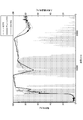
- the anti-oxidation layer 4 is formed and the light reflection layer B is configured to include the anti-alloying transparent layer B3 (see FIG. 2), Si 3 N 4 as a transparent nitride film or a transparent oxide film when changing the thickness of the Al 2 O 3 as a diagram showing the reflectance of the light reflecting layer B.
- the transparent oxide film has a refractive index greatly different from that of the transparent nitride film.
- n 400 nm is 1.67 and n 300 nm is 1.70. Therefore, when the resonance wavelength is calculated, as shown in FIG. 24, when the transparent oxide film is aluminum oxide (Al 2 O 3 ), the film thickness is preferably 60 nm or less, and particularly preferably 44 nm or less. In view of preventing the peeling due to the shear stress due to the difference in the coefficient of thermal expansion of the material, the thinner (thickness) of the alloying prevention transparent layer B3 is better.
- the film thickness (thickness) when the first layer B1 is formed of a silver alloy is the first layer B1.
- the film thickness (thickness) when the second layer B2 is formed of an aluminum alloy is the second layer B2. Can be made equal to the film thickness (thickness) in the case of forming aluminum.
- Adhesion layer 4 Antioxidation layer A Infrared radiation layer B Light reflection layer B1 First layer B2 Second layer B3 Anti-alloying transparent layer
Landscapes
- Physics & Mathematics (AREA)
- Engineering & Computer Science (AREA)
- Thermal Sciences (AREA)
- Mechanical Engineering (AREA)
- General Engineering & Computer Science (AREA)
- General Physics & Mathematics (AREA)
- Optics & Photonics (AREA)
- Health & Medical Sciences (AREA)
- Toxicology (AREA)
- Laminated Bodies (AREA)
- Optical Elements Other Than Lenses (AREA)
- Optical Filters (AREA)
Abstract
La présente invention concerne un dispositif de refroidissement par rayonnement apte à refroidir de manière appropriée une cible de refroidissement tout en réduisant le coût d'une couche réfléchissante optique, et apte à fournir un effet de refroidissement approprié sur une période prolongée. Le dispositif de refroidissement par rayonnement est constitué par stratification d'une couche de rayonnement infrarouge A qui rayonne une lumière infrarouge IR à partir d'une surface de rayonnement H et d'une couche de réflexion de lumière B située sur le côté opposé de la surface de rayonnement H de la couche de rayonnement infrarouge A, et la couche de réflexion de lumière B est constituée par stratification d'une première couche B1 en argent ou en alliage d'argent, une seconde couche B2 constituée d'aluminium ou d'alliage d'aluminium, et une couche transparente résistante à l'alliage B3 servant à empêcher l'alliage d'argent et d'aluminium de telle sorte que la première couche B1, la couche transparente résistante à l'alliage B3, et la seconde couche B2 soient situées plus près de la couche de rayonnement infrarouge A dans cet ordre.
Priority Applications (3)
| Application Number | Priority Date | Filing Date | Title |
|---|---|---|---|
| CN201980014766.6A CN111712738B (zh) | 2018-02-22 | 2019-01-17 | 放射冷却装置 |
| US16/971,602 US20200400391A1 (en) | 2018-02-22 | 2019-01-17 | Radiative Cooling Device |
| JP2020502078A JP6821084B2 (ja) | 2018-02-22 | 2019-01-17 | 放射冷却装置 |
Applications Claiming Priority (2)
| Application Number | Priority Date | Filing Date | Title |
|---|---|---|---|
| JP2018029964 | 2018-02-22 | ||
| JP2018-029964 | 2018-02-22 |
Publications (1)
| Publication Number | Publication Date |
|---|---|
| WO2019163340A1 true WO2019163340A1 (fr) | 2019-08-29 |
Family
ID=67687577
Family Applications (1)
| Application Number | Title | Priority Date | Filing Date |
|---|---|---|---|
| PCT/JP2019/001338 WO2019163340A1 (fr) | 2018-02-22 | 2019-01-17 | Dispositif de refroidissement par rayonnement |
Country Status (4)
| Country | Link |
|---|---|
| US (1) | US20200400391A1 (fr) |
| JP (1) | JP6821084B2 (fr) |
| CN (1) | CN111712738B (fr) |
| WO (1) | WO2019163340A1 (fr) |
Cited By (4)
| Publication number | Priority date | Publication date | Assignee | Title |
|---|---|---|---|---|
| WO2020022156A1 (fr) * | 2018-07-23 | 2020-01-30 | 大阪瓦斯株式会社 | Dispositif de refroidissement par rayonnement |
| CN111497378A (zh) * | 2020-04-20 | 2020-08-07 | 宁波瑞凌新能源科技有限公司 | 辐射制冷金属板、其制备方法及应用 |
| US11874073B2 (en) | 2020-04-09 | 2024-01-16 | The Hong Kong University Of Science And Technology | Radiative cooling structure with enhanced selective infrared emission |
| JP7442366B2 (ja) | 2020-03-27 | 2024-03-04 | 大阪瓦斯株式会社 | 放射冷却装置及び冷却方法 |
Families Citing this family (1)
| Publication number | Priority date | Publication date | Assignee | Title |
|---|---|---|---|---|
| JP6890724B2 (ja) * | 2019-03-27 | 2021-06-18 | 大阪瓦斯株式会社 | 放射冷却装置及び放射冷却方法 |
Citations (5)
| Publication number | Priority date | Publication date | Assignee | Title |
|---|---|---|---|---|
| JP2005276402A (ja) * | 2003-10-10 | 2005-10-06 | Matsushita Electric Ind Co Ltd | 光学的情報記録媒体およびその製造方法 |
| JP2014120487A (ja) * | 2012-12-12 | 2014-06-30 | Kobelco Kaken:Kk | 表示装置または入力装置に用いられる電極、および電極形成用スパッタリングターゲット |
| JP2015018770A (ja) * | 2013-07-12 | 2015-01-29 | パナソニックIpマネジメント株式会社 | 有機エレクトロルミネッセンス素子及び照明装置 |
| US20150338175A1 (en) * | 2014-05-21 | 2015-11-26 | The Board Of Trustees Of The Leland Stanford Junior University | Radiative cooling with solar spectrum reflection |
| WO2016205717A1 (fr) * | 2015-06-18 | 2016-12-22 | The Trustees Of Columbia University In The City Of New York | Systèmes et procédés de chauffage et de refroidissement radiatifs |
Family Cites Families (24)
| Publication number | Priority date | Publication date | Assignee | Title |
|---|---|---|---|---|
| US3813541A (en) * | 1971-05-17 | 1974-05-28 | Columbia Broadcasting Sys Inc | Mos photodiode |
| US3990784A (en) * | 1974-06-05 | 1976-11-09 | Optical Coating Laboratory, Inc. | Coated architectural glass system and method |
| IL86366A0 (en) * | 1988-05-12 | 1988-11-15 | Luz Ind Israel Ltd | Protected silvered substrates and mirrors containing the same |
| ATE188517T1 (de) * | 1996-04-18 | 2000-01-15 | Alusuisse Lonza Services Ag | Aluminiumoberfläche mit interferenzfarben |
| US6531230B1 (en) * | 1998-01-13 | 2003-03-11 | 3M Innovative Properties Company | Color shifting film |
| JP3268446B2 (ja) * | 1999-04-07 | 2002-03-25 | 科学技術振興事業団 | 基板加熱装置 |
| JP2002294440A (ja) * | 2001-04-03 | 2002-10-09 | Sumitomo Chem Co Ltd | スパッタリング用ターゲットとその製造方法 |
| TWI265976B (en) * | 2002-08-08 | 2006-11-11 | Kobe Steel Ltd | Ag base alloy thin film and sputtering target for forming Ag base alloy thin film |
| EP1829835A1 (fr) * | 2006-03-03 | 2007-09-05 | Applied Materials GmbH & Co. KG | Système de couches réfléchissant du royannement infrarouge et la méthode visant sa fabrication |
| US8628820B2 (en) * | 2008-03-11 | 2014-01-14 | Ppg Industries Ohio, Inc. | Reflective article and method of making a reflective article |
| KR20140024416A (ko) * | 2011-05-30 | 2014-02-28 | 아사히 가라스 가부시키가이샤 | 저방사율 적층체 및 복층 유리 |
| JP2013231789A (ja) * | 2012-04-27 | 2013-11-14 | Kiyohara Optics Inc | コーナーキューブリフレクタ、その製造方法、冷媒通過用空間付きミラー及び冷媒通過用空間付きミラーの製造方法 |
| WO2014013042A1 (fr) * | 2012-07-19 | 2014-01-23 | Saint-Gobain Glass France | Ensemble permettant d'éviter la déformation de verre lors de procédés thermiques |
| CN103570360A (zh) * | 2012-07-30 | 2014-02-12 | 伯鑫科技有限公司 | 远红外线散热陶瓷浆料、纤维布、薄膜及其制备方法 |
| WO2014080933A1 (fr) * | 2012-11-21 | 2014-05-30 | 株式会社コベルコ科研 | Electrode mise en oeuvre dans un dispositif d'affichage ou un dispositif d'entrée, et cible de pulvérisation destinée à être utilisée dans la formation d'électrode |
| JP2014167163A (ja) * | 2013-01-31 | 2014-09-11 | Nitto Denko Corp | 赤外線反射フィルムの製造方法 |
| DE102014213819A1 (de) * | 2014-07-16 | 2016-01-21 | Robert Bosch Gmbh | Kaltlichtspiegel und Herstellungsverfahren zum Herstellen eines Kaltlichtspiegels |
| JP6423198B2 (ja) * | 2014-08-05 | 2018-11-14 | 日東電工株式会社 | 赤外線反射フィルム |
| KR102423540B1 (ko) * | 2014-09-19 | 2022-07-20 | 오사까 가스 가부시키가이샤 | 전기 화학 소자, 고체 산화물형 연료 전지 셀, 및 이들의 제조 방법 |
| CN104459848A (zh) * | 2014-11-27 | 2015-03-25 | 中国科学院长春光学精密机械与物理研究所 | 基于氧化铝中间层的铝银多层宽带反射膜 |
| DE102015202195A1 (de) * | 2015-02-06 | 2016-08-11 | Fraunhofer-Gesellschaft zur Förderung der angewandten Forschung e.V. | Laserstrahlung auslenkendes Element |
| JP6597997B2 (ja) * | 2015-03-31 | 2019-10-30 | 大阪瓦斯株式会社 | 熱光発電機 |
| JP6612109B2 (ja) * | 2015-11-20 | 2019-11-27 | 富士フイルム株式会社 | 光学部材およびその製造方法、ディスプレイ、ならびに画像表示装置 |
| AU2017225866B2 (en) * | 2016-02-29 | 2021-10-07 | The Regents Of The University Of Colorado, A Body Corporate | Radiative cooling structures and systems |
-
2019
- 2019-01-17 CN CN201980014766.6A patent/CN111712738B/zh active Active
- 2019-01-17 US US16/971,602 patent/US20200400391A1/en active Pending
- 2019-01-17 JP JP2020502078A patent/JP6821084B2/ja active Active
- 2019-01-17 WO PCT/JP2019/001338 patent/WO2019163340A1/fr active Application Filing
Patent Citations (5)
| Publication number | Priority date | Publication date | Assignee | Title |
|---|---|---|---|---|
| JP2005276402A (ja) * | 2003-10-10 | 2005-10-06 | Matsushita Electric Ind Co Ltd | 光学的情報記録媒体およびその製造方法 |
| JP2014120487A (ja) * | 2012-12-12 | 2014-06-30 | Kobelco Kaken:Kk | 表示装置または入力装置に用いられる電極、および電極形成用スパッタリングターゲット |
| JP2015018770A (ja) * | 2013-07-12 | 2015-01-29 | パナソニックIpマネジメント株式会社 | 有機エレクトロルミネッセンス素子及び照明装置 |
| US20150338175A1 (en) * | 2014-05-21 | 2015-11-26 | The Board Of Trustees Of The Leland Stanford Junior University | Radiative cooling with solar spectrum reflection |
| WO2016205717A1 (fr) * | 2015-06-18 | 2016-12-22 | The Trustees Of Columbia University In The City Of New York | Systèmes et procédés de chauffage et de refroidissement radiatifs |
Cited By (6)
| Publication number | Priority date | Publication date | Assignee | Title |
|---|---|---|---|---|
| WO2020022156A1 (fr) * | 2018-07-23 | 2020-01-30 | 大阪瓦斯株式会社 | Dispositif de refroidissement par rayonnement |
| JPWO2020022156A1 (ja) * | 2018-07-23 | 2020-12-17 | 大阪瓦斯株式会社 | 放射冷却装置 |
| US11427500B2 (en) | 2018-07-23 | 2022-08-30 | Osaka Gas Co., Ltd. | Radiative cooling device |
| JP7442366B2 (ja) | 2020-03-27 | 2024-03-04 | 大阪瓦斯株式会社 | 放射冷却装置及び冷却方法 |
| US11874073B2 (en) | 2020-04-09 | 2024-01-16 | The Hong Kong University Of Science And Technology | Radiative cooling structure with enhanced selective infrared emission |
| CN111497378A (zh) * | 2020-04-20 | 2020-08-07 | 宁波瑞凌新能源科技有限公司 | 辐射制冷金属板、其制备方法及应用 |
Also Published As
| Publication number | Publication date |
|---|---|
| JPWO2019163340A1 (ja) | 2020-12-17 |
| CN111712738B (zh) | 2022-07-15 |
| US20200400391A1 (en) | 2020-12-24 |
| CN111712738A (zh) | 2020-09-25 |
| JP6821084B2 (ja) | 2021-01-27 |
Similar Documents
| Publication | Publication Date | Title |
|---|---|---|
| WO2019163340A1 (fr) | Dispositif de refroidissement par rayonnement | |
| JP6821098B2 (ja) | 放射冷却装置 | |
| JP6821063B2 (ja) | 放射冷却装置 | |
| US9856692B2 (en) | Reduced pressure double glazed glass panel | |
| KR20140057415A (ko) | 스펙트럼 선택 패널 | |
| JP2010055058A (ja) | 広帯域反射鏡 | |
| WO2018180177A1 (fr) | Dispositif de refroidissement par rayonnement et procédé de refroidissement par rayonnement | |
| JP2018536993A (ja) | 光起電力デバイス | |
| JP2018165611A (ja) | 放射冷却装置および放射冷却方法 | |
| JP2017030348A (ja) | 積層膜及び熱線反射材 | |
| JP5896889B2 (ja) | 光学選択膜 | |
| JP7004597B2 (ja) | 放射冷却装置 | |
| JP2010195638A (ja) | 窓用ガラス積層体 | |
| TW201900577A (zh) | 波長選擇透過性玻璃物品 | |
| JPS636504A (ja) | 熱制御フイルム | |
| JP2007145689A (ja) | 近赤外線反射基板およびその基板を用いた近赤外線反射合わせガラス、近赤外線反射複層ガラス | |
| JPH07333423A (ja) | 選択透過膜 | |
| JP7221020B2 (ja) | 太陽光選択吸収体 | |
| KR20190067031A (ko) | 무광 회색 코팅, 무광 회색 코팅 유리 및 복층 유리 | |
| CN114843362A (zh) | 一种制冷结构、光伏组件以及制备方法 | |
| WO2013154462A2 (fr) | Procédé de production de structure semi-conductrice à base de séléniure de plomb | |
| JP2020046446A (ja) | 波長選択透過性合わせガラス |
Legal Events
| Date | Code | Title | Description |
|---|---|---|---|
| 121 | Ep: the epo has been informed by wipo that ep was designated in this application |
Ref document number: 19757209 Country of ref document: EP Kind code of ref document: A1 |
|
| ENP | Entry into the national phase |
Ref document number: 2020502078 Country of ref document: JP Kind code of ref document: A |
|
| NENP | Non-entry into the national phase |
Ref country code: DE |
|
| 122 | Ep: pct application non-entry in european phase |
Ref document number: 19757209 Country of ref document: EP Kind code of ref document: A1 |