WO2019159572A1 - 投影表示装置 - Google Patents
投影表示装置 Download PDFInfo
- Publication number
- WO2019159572A1 WO2019159572A1 PCT/JP2019/000566 JP2019000566W WO2019159572A1 WO 2019159572 A1 WO2019159572 A1 WO 2019159572A1 JP 2019000566 W JP2019000566 W JP 2019000566W WO 2019159572 A1 WO2019159572 A1 WO 2019159572A1
- Authority
- WO
- WIPO (PCT)
- Prior art keywords
- optical path
- concave mirror
- display device
- mirror
- projection
- Prior art date
Links
- 230000003287 optical effect Effects 0.000 claims abstract description 136
- 238000005259 measurement Methods 0.000 claims description 11
- 238000012545 processing Methods 0.000 claims description 8
- 238000013461 design Methods 0.000 description 11
- 238000010586 diagram Methods 0.000 description 4
- 230000000903 blocking effect Effects 0.000 description 3
- 230000008859 change Effects 0.000 description 2
- 230000000694 effects Effects 0.000 description 2
- 238000000034 method Methods 0.000 description 2
- 230000004048 modification Effects 0.000 description 2
- 238000012986 modification Methods 0.000 description 2
- 125000002066 L-histidyl group Chemical group [H]N1C([H])=NC(C([H])([H])[C@](C(=O)[*])([H])N([H])[H])=C1[H] 0.000 description 1
- 230000010485 coping Effects 0.000 description 1
- 230000004907 flux Effects 0.000 description 1
- 239000004973 liquid crystal related substance Substances 0.000 description 1
- 239000000463 material Substances 0.000 description 1
- 230000008569 process Effects 0.000 description 1
Images


Classifications
-
- G—PHYSICS
- G02—OPTICS
- G02B—OPTICAL ELEMENTS, SYSTEMS OR APPARATUS
- G02B7/00—Mountings, adjusting means, or light-tight connections, for optical elements
- G02B7/18—Mountings, adjusting means, or light-tight connections, for optical elements for prisms; for mirrors
- G02B7/182—Mountings, adjusting means, or light-tight connections, for optical elements for prisms; for mirrors for mirrors
- G02B7/1821—Mountings, adjusting means, or light-tight connections, for optical elements for prisms; for mirrors for mirrors for rotating or oscillating mirrors
-
- B—PERFORMING OPERATIONS; TRANSPORTING
- B60—VEHICLES IN GENERAL
- B60K—ARRANGEMENT OR MOUNTING OF PROPULSION UNITS OR OF TRANSMISSIONS IN VEHICLES; ARRANGEMENT OR MOUNTING OF PLURAL DIVERSE PRIME-MOVERS IN VEHICLES; AUXILIARY DRIVES FOR VEHICLES; INSTRUMENTATION OR DASHBOARDS FOR VEHICLES; ARRANGEMENTS IN CONNECTION WITH COOLING, AIR INTAKE, GAS EXHAUST OR FUEL SUPPLY OF PROPULSION UNITS IN VEHICLES
- B60K35/00—Instruments specially adapted for vehicles; Arrangement of instruments in or on vehicles
- B60K35/10—Input arrangements, i.e. from user to vehicle, associated with vehicle functions or specially adapted therefor
-
- B—PERFORMING OPERATIONS; TRANSPORTING
- B60—VEHICLES IN GENERAL
- B60K—ARRANGEMENT OR MOUNTING OF PROPULSION UNITS OR OF TRANSMISSIONS IN VEHICLES; ARRANGEMENT OR MOUNTING OF PLURAL DIVERSE PRIME-MOVERS IN VEHICLES; AUXILIARY DRIVES FOR VEHICLES; INSTRUMENTATION OR DASHBOARDS FOR VEHICLES; ARRANGEMENTS IN CONNECTION WITH COOLING, AIR INTAKE, GAS EXHAUST OR FUEL SUPPLY OF PROPULSION UNITS IN VEHICLES
- B60K35/00—Instruments specially adapted for vehicles; Arrangement of instruments in or on vehicles
- B60K35/20—Output arrangements, i.e. from vehicle to user, associated with vehicle functions or specially adapted therefor
- B60K35/21—Output arrangements, i.e. from vehicle to user, associated with vehicle functions or specially adapted therefor using visual output, e.g. blinking lights or matrix displays
- B60K35/23—Head-up displays [HUD]
-
- B—PERFORMING OPERATIONS; TRANSPORTING
- B60—VEHICLES IN GENERAL
- B60K—ARRANGEMENT OR MOUNTING OF PROPULSION UNITS OR OF TRANSMISSIONS IN VEHICLES; ARRANGEMENT OR MOUNTING OF PLURAL DIVERSE PRIME-MOVERS IN VEHICLES; AUXILIARY DRIVES FOR VEHICLES; INSTRUMENTATION OR DASHBOARDS FOR VEHICLES; ARRANGEMENTS IN CONNECTION WITH COOLING, AIR INTAKE, GAS EXHAUST OR FUEL SUPPLY OF PROPULSION UNITS IN VEHICLES
- B60K35/00—Instruments specially adapted for vehicles; Arrangement of instruments in or on vehicles
- B60K35/60—Instruments characterised by their location or relative disposition in or on vehicles
-
- G—PHYSICS
- G02—OPTICS
- G02B—OPTICAL ELEMENTS, SYSTEMS OR APPARATUS
- G02B26/00—Optical devices or arrangements for the control of light using movable or deformable optical elements
- G02B26/08—Optical devices or arrangements for the control of light using movable or deformable optical elements for controlling the direction of light
- G02B26/0816—Optical devices or arrangements for the control of light using movable or deformable optical elements for controlling the direction of light by means of one or more reflecting elements
-
- G—PHYSICS
- G02—OPTICS
- G02B—OPTICAL ELEMENTS, SYSTEMS OR APPARATUS
- G02B27/00—Optical systems or apparatus not provided for by any of the groups G02B1/00 - G02B26/00, G02B30/00
- G02B27/01—Head-up displays
- G02B27/0101—Head-up displays characterised by optical features
-
- B—PERFORMING OPERATIONS; TRANSPORTING
- B60—VEHICLES IN GENERAL
- B60K—ARRANGEMENT OR MOUNTING OF PROPULSION UNITS OR OF TRANSMISSIONS IN VEHICLES; ARRANGEMENT OR MOUNTING OF PLURAL DIVERSE PRIME-MOVERS IN VEHICLES; AUXILIARY DRIVES FOR VEHICLES; INSTRUMENTATION OR DASHBOARDS FOR VEHICLES; ARRANGEMENTS IN CONNECTION WITH COOLING, AIR INTAKE, GAS EXHAUST OR FUEL SUPPLY OF PROPULSION UNITS IN VEHICLES
- B60K2360/00—Indexing scheme associated with groups B60K35/00 or B60K37/00 relating to details of instruments or dashboards
- B60K2360/122—Instrument input devices with reconfigurable control functions, e.g. reconfigurable menus
-
- B—PERFORMING OPERATIONS; TRANSPORTING
- B60—VEHICLES IN GENERAL
- B60K—ARRANGEMENT OR MOUNTING OF PROPULSION UNITS OR OF TRANSMISSIONS IN VEHICLES; ARRANGEMENT OR MOUNTING OF PLURAL DIVERSE PRIME-MOVERS IN VEHICLES; AUXILIARY DRIVES FOR VEHICLES; INSTRUMENTATION OR DASHBOARDS FOR VEHICLES; ARRANGEMENTS IN CONNECTION WITH COOLING, AIR INTAKE, GAS EXHAUST OR FUEL SUPPLY OF PROPULSION UNITS IN VEHICLES
- B60K2360/00—Indexing scheme associated with groups B60K35/00 or B60K37/00 relating to details of instruments or dashboards
- B60K2360/149—Instrument input by detecting viewing direction not otherwise provided for
-
- B—PERFORMING OPERATIONS; TRANSPORTING
- B60—VEHICLES IN GENERAL
- B60K—ARRANGEMENT OR MOUNTING OF PROPULSION UNITS OR OF TRANSMISSIONS IN VEHICLES; ARRANGEMENT OR MOUNTING OF PLURAL DIVERSE PRIME-MOVERS IN VEHICLES; AUXILIARY DRIVES FOR VEHICLES; INSTRUMENTATION OR DASHBOARDS FOR VEHICLES; ARRANGEMENTS IN CONNECTION WITH COOLING, AIR INTAKE, GAS EXHAUST OR FUEL SUPPLY OF PROPULSION UNITS IN VEHICLES
- B60K2360/00—Indexing scheme associated with groups B60K35/00 or B60K37/00 relating to details of instruments or dashboards
- B60K2360/20—Optical features of instruments
- B60K2360/23—Optical features of instruments using reflectors
-
- B—PERFORMING OPERATIONS; TRANSPORTING
- B60—VEHICLES IN GENERAL
- B60K—ARRANGEMENT OR MOUNTING OF PROPULSION UNITS OR OF TRANSMISSIONS IN VEHICLES; ARRANGEMENT OR MOUNTING OF PLURAL DIVERSE PRIME-MOVERS IN VEHICLES; AUXILIARY DRIVES FOR VEHICLES; INSTRUMENTATION OR DASHBOARDS FOR VEHICLES; ARRANGEMENTS IN CONNECTION WITH COOLING, AIR INTAKE, GAS EXHAUST OR FUEL SUPPLY OF PROPULSION UNITS IN VEHICLES
- B60K2360/00—Indexing scheme associated with groups B60K35/00 or B60K37/00 relating to details of instruments or dashboards
- B60K2360/20—Optical features of instruments
- B60K2360/33—Illumination features
- B60K2360/334—Projection means
-
- B—PERFORMING OPERATIONS; TRANSPORTING
- B60—VEHICLES IN GENERAL
- B60K—ARRANGEMENT OR MOUNTING OF PROPULSION UNITS OR OF TRANSMISSIONS IN VEHICLES; ARRANGEMENT OR MOUNTING OF PLURAL DIVERSE PRIME-MOVERS IN VEHICLES; AUXILIARY DRIVES FOR VEHICLES; INSTRUMENTATION OR DASHBOARDS FOR VEHICLES; ARRANGEMENTS IN CONNECTION WITH COOLING, AIR INTAKE, GAS EXHAUST OR FUEL SUPPLY OF PROPULSION UNITS IN VEHICLES
- B60K2360/00—Indexing scheme associated with groups B60K35/00 or B60K37/00 relating to details of instruments or dashboards
- B60K2360/77—Instrument locations other than the dashboard
- B60K2360/785—Instrument locations other than the dashboard on or in relation to the windshield or windows
-
- G—PHYSICS
- G02—OPTICS
- G02B—OPTICAL ELEMENTS, SYSTEMS OR APPARATUS
- G02B27/00—Optical systems or apparatus not provided for by any of the groups G02B1/00 - G02B26/00, G02B30/00
- G02B27/01—Head-up displays
- G02B27/0149—Head-up displays characterised by mechanical features
- G02B2027/0154—Head-up displays characterised by mechanical features with movable elements
- G02B2027/0159—Head-up displays characterised by mechanical features with movable elements with mechanical means other than scaning means for positioning the whole image
-
- G—PHYSICS
- G02—OPTICS
- G02B—OPTICAL ELEMENTS, SYSTEMS OR APPARATUS
- G02B27/00—Optical systems or apparatus not provided for by any of the groups G02B1/00 - G02B26/00, G02B30/00
- G02B27/01—Head-up displays
- G02B27/0179—Display position adjusting means not related to the information to be displayed
- G02B2027/0181—Adaptation to the pilot/driver
Definitions
- the present invention relates to a projection display apparatus including a display device and an optical system that configures an optical path for projecting light emitted from the display device toward a predetermined projection position as a display image.
- HUD head-up display
- a vehicle HUD apparatus In general, in a vehicle HUD apparatus, light projected from a display device is projected onto a projection position such as a windshield through an optical system constituted by a plurality of optical members, and the light reflected at the projection position is operated. An optical path is formed so as to go to the person's eye point. Accordingly, the driver can visually recognize the display image displayed on the windshield or the like as a virtual image while simultaneously viewing the scenery in front of the vehicle through the windshield.
- the driver's eye point differs depending on the driver's physique and the seating position on the seat. Therefore, in the vehicle HUD device, for example, there are eye points at various positions within the range so that the driver can continue to visually recognize the display image even if the eye points differ within a certain range.
- the optical system is designed to realize various optical paths corresponding to the case. In order to design an optical system assuming such various optical paths, for example, the optical member is enlarged in order to ensure a large incidence range of individual optical members (for example, mirrors) constituting the optical system. It is possible. However, when the optical member is enlarged, the entire HUD device is usually enlarged.
- One of the objects of the present invention is to provide a projection display device capable of coping with various eye points and downsizing the device.
- the projection display device comprises: A display device, and an optical system that configures an optical path for projecting light emitted from the display device toward a predetermined projection position as a display image
- the optical system is A pair of mirrors provided in the middle of the optical path, wherein one of the mirrors is configured such that an optical path convergence point where the light is converged can be set on the optical path, and the other mirror is the optical path While having a pair of mirrors provided at a position corresponding to the convergence point, At least one of the pair of mirrors so as to project the light that has passed through the pair of mirrors and the optical path converging point to the projection position corresponding to the eye point of the user who will visually recognize the display image.
- the mirror surface position can be adjusted while corresponding to the eye point.
- the optical system is An optical member that performs optical processing on the light is provided at a position corresponding to the optical path convergence point.
- the apparatus further includes at least one of a measurement unit that measures the eyepoint regardless of the operation of the user, and an input unit that inputs the eyepoint by the operation of the user.
- the other is placed at a position corresponding to the optical path convergence point set by the one mirror.
- the display image can be continuously projected at the projection position corresponding to the eye point while maintaining the state in which the mirror is present.
- the other mirror is always arranged at a position corresponding to the optical path convergence point regardless of the position of the eye point, the possible incident range of light assumed for the other mirror can be narrowed.
- the entire optical path can be handled without increasing the size. As a result, the projection display device itself can be reduced in size.
- the projection display device According to the projection display device according to the first aspect, it is possible to achieve both compatibility with various eye points and miniaturization of the device.
- the position “corresponding” to the optical path convergence location may be the optical path convergence location itself or may be in the vicinity of the optical path convergence location within a range where the above-described effect can be exhibited.
- an optical member that performs optical processing is disposed at a position corresponding to the optical path convergence point.
- the optical member can be miniaturized for the same reason as the reason why the other mirror described above can be miniaturized.
- it is possible to suppress an increase in the size of the projection display device associated with the arrangement of the optical member.
- a heat cutoff filter, a cold mirror, and the like disposed on the optical path are assumed assuming that sunlight from the outside travels back in the optical path toward the display device. Is done.
- the projection position of the display image can be automatically adjusted by automatically measuring the eye point with the measuring unit.
- the user can operate the input unit to manually adjust the projection position so that the display image is projected onto the projection position suitable for the user's eye point.
- a vehicle HUD device 1 projection display device
- FIG. 1 vehicle longitudinal direction
- vehicle vertical direction front
- rear front
- upper rear
- lower front
- a direction orthogonal to the vehicle longitudinal direction and the vehicle vertical direction is referred to as a “vehicle width direction”.
- the HUD device 1 includes a display device 10, an optical system 20, and a control device 30.
- the display device 10 and the optical system 20 are accommodated inside the dashboard DB of the vehicle.
- the control device 30 may be accommodated inside the dashboard DB or may be disposed outside the dashboard.
- the display device 10 has a display surface 11 that can display an arbitrary two-dimensional image.
- the display device 10 emits light from the display surface 11 toward the front of the vehicle.
- the display device 10 is fixedly arranged on the HUD device 1.
- a transmissive liquid crystal display panel is assumed as the display device 10, but a projector having a screen at the position of the display surface 11 may be used.
- the optical system 20 includes a first concave mirror 21, a second concave mirror 22, a third concave mirror 23, a heat blocking filter 24, and a light shielding plate 25.
- the first concave mirror 21 is positioned in front of the vehicle with respect to the display device 10 and has an aspheric concave mirror surface facing the rear of the vehicle.
- the first concave mirror 21 is supported by the HUD device 1 so as to be rotatable up and down within a predetermined range about a rotation axis extending in the vehicle width direction provided on the back side (opposite side of the mirror surface) of the first concave mirror 21. ing.
- the angle of the first concave mirror 21 can be arbitrarily adjusted by a first actuator 21 a provided on the back side of the first concave mirror 21.
- the angle of the first concave mirror 21 shown in FIG. 1 is a standard design angle within the adjustment range.
- the second concave mirror 22 is positioned behind the vehicle and above the display device 10 and has an aspheric concave mirror surface facing the front of the vehicle.
- the second concave mirror 22 is supported by the HUD device 1 so as to be rotatable up and down within a predetermined range around a rotation axis extending in the vehicle width direction provided on its back side (opposite to the mirror surface). ing.
- the angle of the second concave mirror 22 can be arbitrarily adjusted by a second actuator 22a provided on its back side.
- the angle of the second concave mirror 22 shown in FIG. 1 is a standard design angle within the adjustment range.
- the third concave mirror 23 has an aspheric concave mirror surface that is located in front of the vehicle and above the first concave mirror 21 and just below the opening H and facing the rear of the vehicle.
- the third concave mirror 23 is fixedly disposed on the HUD device 1 (non-rotatable).
- the light emitted from the display surface 11 of the display device 10 toward the front of the vehicle passes through the optical path (light flux) L1 toward the first concave mirror 21, and the light incident on the mirror surface of the first concave mirror 21 is the mirror surface.
- the light that is reflected by the light beam and passes through the optical path (light beam) L2 toward the second concave mirror 22 and is incident on the mirror surface of the second concave mirror 22 is reflected by the mirror surface and passes through the optical path (light beam) L3.
- the light that is directed to the mirror 23 and is incident on the mirror surface of the third concave mirror 23 is reflected by the mirror surface, is emitted from the opening H through the optical path (light beam) L4, and is the inner surface (projection surface) of the windshield WS. Is projected onto the projection position P.
- the light projected on the projection position P of the windshield WS is reflected by the projection surface of the windshield WS and travels to the driver's eye point EP through an optical path (light beam) L5.
- An eye point EP shown in FIG. 1 indicates a standard position in design of the driver's eye point. Therefore, the projection position P shown in FIG. 1 corresponding to the eye point EP shown in FIG. 1 indicates a standard position for designing the projection position.
- Optical paths (light beams) L1 to L5 indicate design standard optical paths through which light constituting a display image visually recognized by the driver at the eye point EP passes.
- this standard optical path for example, when viewed from the second concave mirror 22 side, the optical path L2 converges at an optical path convergence point C that is one point on the mirror surface of the first concave mirror 21.
- the mirror surface of the first concave mirror 21 is located at the optical path convergence point C of the optical path L2 formed by the concave shape of the mirror surface of the second concave mirror 22.
- the driver can visually recognize the display image projected by the HUD device 1 at the eye point EP.
- the display image actually viewed by the driver is formed as a virtual image VI at a predetermined position in front of the vehicle with respect to the windshield WS.
- the light emitted from the HUD device 1 is reflected by the projection surface of the windshield WS and guided to the eyepoint EP.
- an optical device such as a combiner or a half mirror is used instead of the windshield WS.
- a reflection member may be employed, and the light emitted from the HUD device 1 may be reflected by the projection surface of the optical reflection member and guided to the eye point EP.
- the light shielding plate 25 is fixedly disposed on the HUD device 1 at a position and an orientation between the first concave mirror 21 and the third concave mirror 23 so as not to interfere with the optical paths L2 and L3. As shown in FIG. 4, the light shielding plate 25 allows the light emitted from the display device 10 to reach the eye point EP through an optical path Lg different from the regular optical paths L1, L2, L3, L4, and L5. This is provided to prevent the driver from visually recognizing an image different from the regular display image (so-called ghost image).
- the optical path L2 of the present embodiment converges at the optical path convergence point C, which is one point on the mirror surface of the first concave mirror 21, and the mirror surface of the first concave mirror 21 is located at this optical path convergence point C. ing. That is, the width of the optical path L2 becomes narrower as the first concave mirror 21 is approached. Therefore, the freedom degree of arrangement
- the light shielding plate 25 also has a function of shielding sunlight from the outside so as to suppress the display device 10 from being exposed to sunlight.
- the optical path L ⁇ b> 2 is converged between the first concave mirror 21 and the second concave mirror 22. Therefore, there is a margin in the internal space of the HUD device 1 as much as the optical path L2 is converged. Therefore, the light shielding plate 25 can be enlarged using this margin. By increasing the size of the light shielding plate 25, it is possible to more reliably shield sunlight reaching the display device 10.
- the control device 30 includes a display device 10, a first actuator 21 a, a second actuator 22 a, and an eye point measurement camera 31 provided at a predetermined position above the inner side surface of the windshield WS. And are electrically connected.
- the control device 30 is, for example, a microcomputer.
- the eye point measurement camera 31 is a camera that photographs around the driver's face (eyes) in order to measure the position of the driver's eye point EP.
- the control device 30 displays various images on the display surface 11 of the display device 10 according to the state of the vehicle. In other words, the control device 30 controls the light emitted from the display device 10.
- the control device 30 adjusts the angle of the first concave mirror 21 by controlling the first actuator 21a.
- the control device 30 adjusts the angle of the second concave mirror 22 by controlling the second actuator 22a.
- the control device 30 analyzes the image taken by the eye point measurement camera 31, and measures the position of the driver's eye point EP.
- the position of the eye point EP differs depending on, for example, the driver's physique. If the eye point EP is different, the projection position P corresponding to the eye point EP on the projection surface of the windshield WS is also different.
- the angles of the first concave mirror 21 and the second concave mirror 22 are changed from the standard angle shown in FIG.
- the angle of the first concave mirror 21 is changed downward from the standard angle shown in FIG. 1
- the angle of the second concave mirror 22 is changed upward from the standard angle shown in FIG. Yes.
- the optical path L2a shown in FIG. 2 (a) is also an optical path convergence point which is one point on the mirror surface of the first concave mirror 21 when viewed from the second concave mirror 22 side, similarly to the optical path L2 shown in FIG. Converged with Ca.
- the optical path convergence point Ca on the mirror surface of the first concave mirror 21, the optical path convergence point Ca (see FIG. 2A) is slightly above the optical path convergence point C (see FIG. 1). Will be moved to.
- the angles of the first concave mirror 21 and the second concave mirror 22 are changed from the standard angles shown in FIG.
- the angle of the first concave mirror 21 is changed upward from the standard angle shown in FIG. 1
- the angle of the second concave mirror 22 is changed downward from the standard angle shown in FIG. Yes.
- the optical path L2b shown in FIG. 2 (b) is also an optical path convergence point which is one point on the mirror surface of the first concave mirror 21 when viewed from the second concave mirror 22 side, similarly to the optical path L2 shown in FIG. Convergence at Cb.
- the optical path convergence point Cb is slightly below the optical path convergence point C (see FIG. 1). Will be moved to.
- control device 30 of the HUD device 1 adjusts the angles of the first concave mirror 21 and the second concave mirror 22 according to the position of the eye point EP.
- the flow of processing will be described.
- the control device 30 repeatedly executes the process shown in FIG. 3 at a predetermined timing.
- the control device 30 first determines whether or not the HUD device 1 is in an operating state (step S1). When the HUD device 1 is not in the operating state (No in step S1), the control device 30 maintains the display device 10 in the OFF state (step S6). On the other hand, when the HUD device 1 is in an operating state (Yes in step S1), the control device 30 turns on the display device 10 (step S2).
- control device 30 analyzes the image captured by the eye point measurement camera 31 using one of known methods, and measures the position of the driver's eye point EP (step S3).
- step S2 The eyepoint measured in step S2 while maintaining the state where the mirror surface of the first concave mirror 21 is located at the optical path convergence point C of the optical path L2 generated by the second concave mirror 22 as a result of the processing described above by the control device 30.
- a display image is projected to the projection position P corresponding to EP.
- the angles of the first concave mirror 21 and the second concave mirror 22 are changed even when the eye point EP moves within a range assumed in design.
- the state in which the mirror surface of the first concave mirror 21 is located at the optical path convergence portion of the optical path L2 generated by the second concave mirror 22 is maintained.
- a display image can be projected onto the projection position P corresponding to the eye point EP on the projection surface of the windshield WS. Therefore, even if the eye point EP moves within the range assumed in design, the driver can continue to visually recognize the display image.
- the mirror surface of the first concave mirror 21 is always arranged at the optical path convergence point of the optical path L2 even if the eye point EP moves within the range assumed in the design, the assumption on the mirror surface of the first concave mirror 21 is assumed. It is possible to narrow the incident range of the emitted light.
- the first concave mirror 21 can be made extremely small by designing the optical system 20 so that the intervals between the optical path convergence points C, Ca, and Cb shown in FIG. As a result, the entire HUD device 1 can be reduced in size.
- the heat shutoff filter 24 is disposed in the vicinity of the first concave mirror 21 on the optical path L2 between the first concave mirror 21 and the second concave mirror 22 (that is, in the vicinity of the optical path converging portion of the optical path). ing. As a result, it is possible to narrow the assumed light incidence range in the heat cutoff filter 24. For this reason, the heat cutoff filter 24 can be made small for the same reason as the first concave mirror 21. As a result, the enlargement of the entire HUD device 1 associated with the arrangement of the heat cutoff filter 24 can be suppressed.
- the first concave mirror 21, the second concave mirror 22, and the third concave mirror 23 are aspherical mirrors having a convex shape.
- an aspherical mirror having a convex shape or an aspherical mirror in which a concave surface and a convex surface are mixed may be used.
- the 3rd concave mirror 23 may be further rotatable.
- the eye point EP is automatically measured using the image taken by the eye point measuring camera 31, and the projection position P is automatically adjusted.
- an input unit such as an adjustment lever that can be operated by the driver may be provided instead of the eye point measurement camera 31, and the projection position P can be manually adjusted so that the projection position P according to his / her eye point EP can be obtained.
- the projection position P on the projection plane of the windshield WS is changed by changing the angles of both the first concave mirror 21 and the second concave mirror 22.
- the optical system 20 includes the heat cutoff filter 24 and the light shielding plate 25.
- the heat cutoff filter 24 and the light shielding plate 25 may be omitted from the optical system 20.
- a projection display device (1) comprising: The optical system is It is a pair of mirrors (21, 22) provided in the middle of the optical path, and one of the mirrors (22) can set an optical path convergence point (C) where the light is converged on the optical path.
- the other mirror (21) has a pair of mirrors provided at positions corresponding to the optical path convergence locations, The pair of the mirrors and the light path converging points are projected onto the projection position (P) corresponding to the eye point (EP) of the user who will visually recognize the display image.
- the mirror surface position of at least one of the mirrors can be adjusted while corresponding to the eye point.
- Projection display device [2] In the projection display device according to [1] above,
- the optical system is An optical member (24) for optically processing the light is provided at a position corresponding to the optical path convergence point. Projection display device.
- the projection display device according to [1] or [2] above, It further comprises at least one of a measurement unit (31) that measures the eye point regardless of the user's operation, and an input unit that inputs the eye point by the user's operation, Projection display device.
- the projection display device of the present invention can achieve both compatibility with various eye points and miniaturization of the device.
- the present invention having this effect can be used, for example, in a head-up display (HUD) device for a vehicle.
- HUD head-up display
Landscapes
- Engineering & Computer Science (AREA)
- Physics & Mathematics (AREA)
- Chemical & Material Sciences (AREA)
- Combustion & Propulsion (AREA)
- Transportation (AREA)
- Mechanical Engineering (AREA)
- General Physics & Mathematics (AREA)
- Optics & Photonics (AREA)
- Instrument Panels (AREA)
Abstract
投影表示装置(1)は、光学系(20)を構成する一対のミラー(21,22)を備える。一方のミラー(22)は光路収束箇所(C)を光路(L2)上に構成し、他方のミラー(21)は光路収束箇所に対応した位置に設けられる。ミラー(21,22)及び光路収束箇所(C)を経た光をユーザのアイポイント(EP)に対応した投影位置(P)に投影するように、少なくとも一方のミラー(22)の鏡面位置がアイポイントに基づいて調整される。
Description
本発明は、表示デバイスと、表示デバイスから放たれた光を所定の投影位置に向けて表示像として投影する光路を構成する光学系と、を備えた投影表示装置に関する。
従来から、車両の運転者が車速表示やナビゲーションシステムの案内表示などの表示像を見る際の視認性を向上させるため、車両用のヘッドアップディスプレイ(HUD)装置を利用することが広く知られている(例えば、特許文献1,2を参照)。
一般に、車両用のHUD装置では、表示デバイスから投射された光が、複数の光学部材などによって構成される光学系を経てウインドシールド等の投影位置に投影され、投影位置において反射したその光が運転者のアイポイントに向かうように、光路が形成される。これにより、運転者は、ウインドシールドを通して車両の前方の風景を視認しながら、同時にウインドシールド等に映る表示像を虚像として視認することができる。
一般に、運転者のアイポイントは、運転者の体格やシートへの着座位置などによって相違する。そこで、車両用のHUD装置では、例えば、アイポイントがある程度の範囲内で相違しても運転者が表示像を視認し続けることができるように、その範囲内の様々な位置にアイポイントが存在する場合に対応した様々な光路を実現するように光学系が設計される。このような様々な光路を想定して光学系を設計するためには、例えば、光学系を構成する個々の光学部材(例えば、ミラー)の入射可能範囲を大きく確保するべく、光学部材を大きくすることが考えられる。ところが、光学部材が大型化すると、通常、HUD装置全体も大型化することになる。
本発明の目的の一つは、様々なアイポイントへの対応と、装置の小型化と、を両立可能な投影表示装置の提供である。
(1)本発明の第1の側面において、投影表示装置は、
表示デバイスと、前記表示デバイスから放たれた光を所定の投影位置に向けて表示像として投影する光路を構成する光学系と、を備え、
前記光学系は、
前記光路の途中に設けられた一対のミラーであって、一方の前記ミラーは前記光が収束された光路収束箇所を前記光路上に設定可能であるように構成され、他方の前記ミラーは前記光路収束箇所に対応した位置に設けられる、一対のミラーを有すると共に、
前記表示像を視認することになるユーザのアイポイントに対応した前記投影位置に、前記一対の前記ミラー及び前記光路収束箇所を経た前記光を投影するように、前記一対の前記ミラーの少なくとも一方の鏡面位置を前記アイポイントに対応させながら調整可能である、ように構成される。
(2)本発明の第2の側面では、第1の側面に係る投影表示装置において、
前記光学系は、
前記光に光学的処理を施す光学部材を前記光路収束箇所に対応した位置に有する。
前記光学系は、
前記光に光学的処理を施す光学部材を前記光路収束箇所に対応した位置に有する。
(3)本発明の第3の側面では、第1の側面又は第2の側面に係る投影表示装置において、
前記アイポイントを前記ユーザの操作によらず測定する測定部、及び、前記アイポイントを前記ユーザの操作によって入力する入力部、の少なくとも一方を、更に備える。
前記アイポイントを前記ユーザの操作によらず測定する測定部、及び、前記アイポイントを前記ユーザの操作によって入力する入力部、の少なくとも一方を、更に備える。
上記第1の側面では、アイポイントが種々の理由によって相違しても、一対のミラーの少なくとも一方の鏡面位置を調整することで、一方のミラーによって設定される光路収束箇所に対応した位置に他方のミラーが存在する状態を維持しながら、アイポイントに対応した投影位置に表示像を投影させ続けることができる。更に、アイポイントの位置にかかわらず常に他方のミラーが光路収束箇所に対応した位置に配置されるため、他方のミラーに想定される光の入射可能範囲を狭くすることができ、他方のミラーを大型化させることなく様々な光路の全体に対応できる。その結果、投影表示装置そのものを小型化できる。
よって、第1の側面に係る投影表示装置によれば、様々なアイポイントへの対応と、装置の小型化と、を両立可能である。
なお、光路収束箇所に「対応した」位置とは、光路収束箇所そのものであっても、上述した効果を発揮可能な程度の範囲内で光路収束箇所の近傍であってもよい。
上記第2の側面では、光路収束箇所に対応した位置に、光学的処理を施す光学部材を配置する。これにより、上述した他方のミラーを小型化できる理由と同様の理由により、光学部材を小型化できる。その結果、光学部材を配置することに伴う投影表示装置の大型化を抑制できる。なお、このような光学部材としては、典型的には、外部からの太陽光が光路を逆行して表示デバイスに向かう場合を想定して光路上に配置される熱遮断フィルタ及びコールドミラー等が想定される。
上記第3の側面では、アイポイントを測定部で自動測定することで、表示像の投影位置を自動的に調整できる。または、ユーザが入力部を操作することで、自分のアイポイントに適した投影位置に表示像が投影されるように投影位置を手動で調整できる。
本発明によれば、様々なアイポイントへの対応と、装置の小型化と、を両立可能である。
以上、本発明について簡潔に説明した。更に、以下に説明される発明を実施するための形態(以下、「実施形態」という。)を添付の図面を参照して通読することにより、本発明の詳細は更に明確化されるであろう。
<実施形態>
以下、図1、図2(a)~図2(c)、図3及び図4を参照しながら、本発明の実施形態に係る車両用のHUD装置1(投影表示装置)について説明する。以下、説明の便宜上、図1に示すように、「車両前後方向」、「車両上下方向」、「前」、「後」、「上」、及び「下」を定義する。車両前後方向及び車両上下方向は、互いに直交している。また、車両前後方向及び車両上下方向に直交する方向(図1において紙面奥行方向)を「車両幅方向」と称呼する。
以下、図1、図2(a)~図2(c)、図3及び図4を参照しながら、本発明の実施形態に係る車両用のHUD装置1(投影表示装置)について説明する。以下、説明の便宜上、図1に示すように、「車両前後方向」、「車両上下方向」、「前」、「後」、「上」、及び「下」を定義する。車両前後方向及び車両上下方向は、互いに直交している。また、車両前後方向及び車両上下方向に直交する方向(図1において紙面奥行方向)を「車両幅方向」と称呼する。
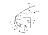
図1に示すように、HUD装置1は、車両のダッシュボードDBの上面の一部分に形成した開口部Hから、光を車両のウインドシールドWSに投影できるように構成されている。表示像としては、典型的には、車両の運転に役立つ情報(例えば、車速表示、ナビゲーションシステムの案内表示)が挙げられる。
HUD装置1は、表示デバイス10と、光学系20と、制御装置30と、を備える。表示デバイス10及び光学系20は、車両のダッシュボードDBの内側に収容されている。制御装置30は、ダッシュボードDBの内側に収容されていても、ダッシュボードの外側に配置されていてもよい。
表示デバイス10は、任意の二次元画像を表示可能な表示面11を有する。表示デバイス10は、表示面11から車両前方に向けて光を出射するようになっている。表示デバイス10は、HUD装置1に固定配置されている。表示デバイス10としては、典型的には、透過型液晶表示パネルが想定されるが、表示面11の位置にスクリーンを有するプロジェクタが使用されてもよい。
光学系20は、第1凹面ミラー21と、第2凹面ミラー22と、第3凹面ミラー23と、熱遮断フィルタ24と、遮光板25と、を含んで構成されている。
第1凹面ミラー21は、表示デバイス10に対して車両前方に位置し、車両後方を向いた非球面の凹形状の鏡面を有する。第1凹面ミラー21は、自身の背面側(鏡面とは反対側)に設けられた車両幅方向に延びる回転軸を中心に所定範囲内にて上下に回動可能に、HUD装置1に支持されている。第1凹面ミラー21の角度は、自身の背面側に設けられた第1アクチュエータ21aによって任意に調整可能となっている。図1に示す第1凹面ミラー21の角度は、調整範囲内における設計上の標準角度を示している。
第2凹面ミラー22は、表示デバイス10に対して車両後方かつ車両上方に位置し、車両前方を向いた非球面の凹形状の鏡面を有する。第2凹面ミラー22は、自身の背面側(鏡面とは反対側)に設けられた車両幅方向に延びる回転軸を中心に所定範囲内にて上下に回動可能に、HUD装置1に支持されている。第2凹面ミラー22の角度は、自身の背面側に設けられた第2アクチュエータ22aによって任意に調整可能となっている。図1に示す第2凹面ミラー22の角度は、調整範囲内における設計上の標準角度を示している。
第3凹面ミラー23は、第1凹面ミラー21に対して車両前方かつ車両上方で、且つ、開口部Hの直下に位置し、車両後方を向いた非球面の凹形状の鏡面を有する。第3凹面ミラー23は、HUD装置1に(回動不能に)固定配置されている。
表示デバイス10の表示面11から車両前方に向けて出射された光は、光路(光束)L1を通って第1凹面ミラー21に向かい、第1凹面ミラー21の鏡面に入射した光は、当該鏡面で反射されて光路(光束)L2を通って第2凹面ミラー22に向かい、第2凹面ミラー22の鏡面に入射した光は、当該鏡面で反射されて光路(光束)L3を通って第3凹面ミラー23に向かい、第3凹面ミラー23の鏡面に入射した光は、当該鏡面で反射されて光路(光束)L4を通って開口部Hから出射されて、ウインドシールドWSの内側面(投影面)の投影位置Pに投影される。
ウインドシールドWSの投影位置Pに投影された光は、ウインドシールドWSの投影面で反射されて光路(光束)L5を通って運転者のアイポイントEPに向かう。図1に示すアイポイントEPは、運転者のアイポイントの設計上の標準位置を示している。よって、図1に示すアイポイントEPに対応する図1に示す投影位置Pは、投影位置の設計上の標準位置を示す。
光路(光束)L1~L5は、運転者がアイポイントEPで視認する表示像を構成する光が通過する設計上の標準光路を示す。この標準光路において、例えば光路L2は、第2凹面ミラー22側から見たとき、第1凹面ミラー21の鏡面上の1点である光路収束箇所Cで収束している。換言すれば、第2凹面ミラー22の鏡面の凹形状によって形成される光路L2の光路収束箇所Cに第1凹面ミラー21の鏡面が位置している。
運転者は、アイポイントEPで、HUD装置1が投射する表示像を視認することができる。実際に運転者が視認する表示像は、ウインドシールドWSよりも車両前方の所定の位置に虚像VIとして結像される。
なお、図1に示す例では、HUD装置1が出射した光をウインドシールドWSの投影面で反射してアイポイントEPに導いているが、ウインドシールドWSに代えて、コンバイナ又はハーフミラー等の光学反射部材を採用し、HUD装置1が出射した光をこの光学反射部材の投影面で反射してアイポイントEPに導くように構成してもよい。
熱遮断フィルタ24は、第1凹面ミラー21と第2凹面ミラー22との間の光路L2上における第1凹面ミラー21の近傍位置(即ち、光路L2の光路収束箇所Cの近傍位置)において、HUD装置1に固定配置されている。熱遮断フィルタ24は、表示デバイス10から出射される光を透過し、太陽光を遮断する特性を有するフィルタである。熱遮断フィルタ24は、外部からの太陽光が、光路L4,L3,L2,L1を逆行して表示デバイス10に向かい、表示デバイス10が太陽光の熱によって過度に加熱されること等を防止するために設けられている。
遮光板25は、第1凹面ミラー21と第3凹面ミラー23との間において光路L2,L3に干渉しない位置及び向きで、HUD装置1に固定配置されている。遮光板25は、図4に示すように、表示デバイス10から出射された光が、正規の光路L1,L2,L3,L4,L5とは異なる光路Lgを通ってアイポイントEPに到達することで、運転者が正規の表示像とは別の像(所謂ゴースト像)を視認することを防止するために設けられている。
上述の通り、本実施形態の光路L2は第1凹面ミラー21の鏡面上の1点である光路収束箇所Cで収束しており、この光路収束箇所Cに第1凹面ミラー21の鏡面が位置している。即ち、第1凹面ミラー21に近付くにつれて光路L2の幅が細くなっている。よって、遮光板25の配置の自由度が向上し、HUD装置1全体の大型化が抑制される。
更に、遮光板25は、表示デバイス10が太陽光に曝されることを抑制するように、外部からの太陽光を遮る機能も有する。ここで、上述したように、HUD装置1では第1凹面ミラー21と第2凹面ミラー22との間で光路L2が収束される。そのため、光路L2が収束された分だけ、HUD装置1の内部空間に余裕ができる。そこで、この余裕を利用し、遮光板25を大型化できる。遮光板25を大型化することで、表示デバイス10に到達する太陽光をより確実に遮光できることになる。
制御装置30は、図1に示すように、表示デバイス10、第1アクチュエータ21a、第2アクチュエータ22a、及び、ウインドシールドWSの内側面の上側の所定位置に設けられているアイポイント測定用カメラ31と、電気的に接続されている。制御装置30は、例えば、マイクロコンピュータである。アイポイント測定用カメラ31は、運転者のアイポイントEPの位置を測定するために、運転者の顔(目)の周りを撮影するカメラである。
制御装置30は、車両の状態に応じて、表示デバイス10の表示面11に様々な画像を表示させる。換言すると、制御装置30は、表示デバイス10から出射される光を制御するようになっている。制御装置30は、第1アクチュエータ21aを制御することで、第1凹面ミラー21の角度を調整するようになっている。制御装置30は、第2アクチュエータ22aを制御することで、第2凹面ミラー22の角度を調整するようになっている。制御装置30は、アイポイント測定用カメラ31が撮影した画像を解析して、運転者のアイポイントEPの位置を測定するようになっている。
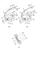
次いで、図2を参照しながら、アイポイントEPの位置に応じた第1凹面ミラー21及び第2凹面ミラー22の角度の調整について説明する。アイポイントEPの位置は、例えば、運転者の体格等によって相違する。アイポイントEPが異なれば、ウインドシールドWSの投影面上における、アイポイントEPに対応する投影位置Pも異なる。
具体的には、図2(a)に示すように、アイポイントEPが図1に示す標準位置から上方に移動した位置にある場合、ウインドシールドWSの投影面上における、アイポイントEPに対応する投影位置Pも、図1に示す標準位置から上方に移動する。このように、投影位置Pを図1に示す標準位置から上方に移動するためには、表示デバイス10からウインドシールドWSの投影面までの光路を、図1に示す標準の光路L1,L2,L3,L4,L5から、図2(a)に示す光路L1a,L2a,L3a,L4a,L5aに変更する必要がある。
このような光路の変更のため、図2(a)に示すように、第1凹面ミラー21及び第2凹面ミラー22の角度が図1に示す標準角度から変更される。図2(a)に示す例では、第1凹面ミラー21の角度が図1に示す標準角度から下向きに変更され、第2凹面ミラー22の角度が図1に示す標準角度から上向きに変更されている。
ここで、図2(a)に示す光路L2aも、図1に示す光路L2と同様、第2凹面ミラー22側から見たとき、第1凹面ミラー21の鏡面上の1点である光路収束箇所Caで収束している。このとき、図2(c)に示すように、第1凹面ミラー21の鏡面上において、光路収束箇所Ca(図2(a)参照)は、光路収束箇所C(図1参照)よりも若干上方に移動することになる。
一方、図2(b)に示すように、アイポイントEPが図1に示す標準位置から下方に移動した位置にある場合、ウインドシールドWSの投影面上における、アイポイントEPに対応する投影位置Pも、図1に示す標準位置から下方に移動する。このように、投影位置Pを図1に示す標準位置から下方に移動するためには、表示デバイス10からウインドシールドWSの投影面までの光路を、図1に示す標準の光路L1,L2,L3,L4,L5から、図2(b)に示す光路L1b,L2b,L3b,L4b,L5bに変更する必要がある。
このような光路の変更のため、図2(b)に示すように、第1凹面ミラー21及び第2凹面ミラー22の角度が図1に示す標準角度から変更される。図2(b)に示す例では、第1凹面ミラー21の角度が図1に示す標準角度から上向きに変更され、第2凹面ミラー22の角度が図1に示す標準角度から下向きに変更されている。
ここで、図2(b)に示す光路L2bも、図1に示す光路L2と同様、第2凹面ミラー22側から見たとき、第1凹面ミラー21の鏡面上の1点である光路収束箇所Cbで収束している。このとき、図2(c)に示すように、第1凹面ミラー21の鏡面上において、光路収束箇所Cb(図2(b)参照)は、光路収束箇所C(図1参照)よりも若干下方に移動することになる。
このように、HUD装置1では、アイポイントEPが設計上想定される範囲内で上下に移動しても、第1凹面ミラー21及び第2凹面ミラー22の角度を変更することで、第2凹面ミラー22による光路L2の光路収束箇所に第1凹面ミラー21の鏡面が位置する状態が維持される。その結果、ウインドシールドWSの投影面上におけるアイポイントEPに対応した投影位置Pに、表示像が投影される。よって、アイポイントEPが設計上想定される範囲内で上下に移動しても、運転者が表示像を視認し続けることができる。
次いで、図3に示すフローチャートを参照しながら、HUD装置1の制御装置30が、アイポイントEPの位置に応じて第1凹面ミラー21及び第2凹面ミラー22の角度を調整する際の具体的な処理の流れについて説明する。制御装置30は、所定のタイミングにて、図3に示す処理を繰り返し実行する。
制御装置30は、まず、HUD装置1が作動状態であるか否かを判定する(ステップS1)。HUD装置1が作動状態でない場合(ステップS1でNo)、制御装置30は、表示デバイス10をOFF状態に維持する(ステップS6)。一方、HUD装置1が作動状態である場合(ステップS1でYes)、制御装置30は、表示デバイス10をON状態にする(ステップS2)。
次いで、制御装置30は、アイポイント測定用カメラ31が撮影した画像を公知の手法の1つを用いて解析し、運転者のアイポイントEPの位置を測定する(ステップS3)。
アイポイントEPの位置の測定が完了すると、制御装置30は、測定されたアイポイントEPの位置に応じた第1凹面ミラー21及び第2凹面ミラー22の角度を算出する(ステップS4)。制御装置30は、第1凹面ミラー21及び第2凹面ミラー22の実際の角度と、算出された角度と、が一致するように、第1アクチュエータ21a及び第2アクチュエータ22aを制御する(ステップS5)。以上の処理により、第1凹面ミラー21及び第2凹面ミラー22の角度の調整が完了する。
制御装置30による上述した処理の結果、第2凹面ミラー22によって発生する光路L2の光路収束箇所Cに第1凹面ミラー21の鏡面が位置する状態を維持しながら、ステップS2で測定されたアイポイントEPに対応した投影位置Pに表示像が投影されることになる。
以上、本発明の実施形態に係るHUD装置1によれば、アイポイントEPが設計上想定される範囲内で移動しても、第1凹面ミラー21及び第2凹面ミラー22の角度を変更することで、第2凹面ミラー22によって発生する光路L2の光路収束箇所に第1凹面ミラー21の鏡面が位置する状態が維持される。その結果、ウインドシールドWSの投影面上におけるアイポイントEPに対応した投影位置Pに表示像が投影され得る。よって、アイポイントEPが設計上想定される範囲内で移動しても、運転者が表示像を視認し続けることができる。
加えて、アイポイントEPが設計上想定される範囲内で移動しても、第1凹面ミラー21の鏡面が光路L2の光路収束箇所に常に配置されるため、第1凹面ミラー21の鏡面における想定される光の入射範囲を狭くすることが可能となる。このとき、図2(c)に示す光路収束箇所C,Ca,Cbの間隔が狭くなるように光学系20を設計することで、第1凹面ミラー21を極めて小さくすることができる。この結果、HUD装置1全体の小型化が可能である。
よって、HUD装置1によれば、アイポイントEPが設計上想定される範囲内で移動しても運転者が表示像を視認し続けることができ、且つ、HUD装置1全体の小型化が可能となる。
更に、熱遮断フィルタ24が、第1凹面ミラー21と第2凹面ミラー22との間の光路L2上における第1凹面ミラー21の近傍位置(即ち、光路の光路収束箇所の近傍位置)に配置されている。この結果、熱遮断フィルタ24における想定される光の入射範囲を狭くすることが可能となる。このため、第1凹面ミラー21と同様の理由で、熱遮断フィルタ24を小さくすることができる。その結果、熱遮断フィルタ24を配置することに伴うHUD装置1全体の大型化が抑制され得る。
上記実施形態では、第1凹面ミラー21、第2凹面ミラー22及び第3凹面ミラー23は、凸面形状を有する非球面ミラーである。これに対し、凸面形状を有する非球面ミラーや凹面と凸面とが混在した非球面ミラーが用いられてもよい。また、上記実施形態では、第1凹面ミラー21及び第2凹面ミラー22が回動可能となっているが、更に第3凹面ミラー23が回動可能となっていてもよい。
更に、アイポイント測定用カメラ31が撮影した画像を用いてアイポイントEPを自動で測定することで、第1凹面ミラー21及び第2凹面ミラー22の角度、ひいては、ウインドシールドWSの投影面上における表示像の投影位置Pを、自動で調整することができる。
<他の形態>
なお、本発明は上記各実施形態に限定されることはなく、本発明の範囲内において種々の変形例を採用することができる。例えば、本発明は、上述した実施形態に限定されるものではなく、適宜、変形、改良、等が可能である。その他、上述した実施形態における各構成要素の材質、形状、寸法、数、配置箇所、等は本発明を達成できるものであれば任意であり、限定されない。
なお、本発明は上記各実施形態に限定されることはなく、本発明の範囲内において種々の変形例を採用することができる。例えば、本発明は、上述した実施形態に限定されるものではなく、適宜、変形、改良、等が可能である。その他、上述した実施形態における各構成要素の材質、形状、寸法、数、配置箇所、等は本発明を達成できるものであれば任意であり、限定されない。
例えば、上記実施形態では、アイポイント測定用カメラ31が撮影した画像を用いてアイポイントEPを自動で測定し、投影位置Pを自動で調整している。これに対し、アイポイント測定用カメラ31に代えて、運転者が操作可能な調整レバー等の入力部を設けてもよい。この場合、運転者が入力部を操作することで、自分のアイポイントEPに合わせた投影位置Pが得られるように投影位置Pを手動で調整することができる。
更に、上記実施形態では、第1凹面ミラー21及び第2凹面ミラー22の双方の角度を変更することで、ウインドシールドWSの投影面上における投影位置Pを変更している。これに対し、第1凹面ミラー21及び第2凹面ミラー22の何れか一方のみの角度を変更することで、ウインドシールドWSの投影面上における投影位置Pを変更するように構成してもよい。
更に、上記実施形態では、光学系20に熱遮断フィルタ24及び遮光板25が含まれている。これに対し、熱遮断フィルタ24及び遮光板25の何れか一方又は双方が、光学系20から省略されてもよい。
ここで、上述した本発明に係るHUD装置1(投影表示装置)の実施形態の特徴をそれぞれ以下[1]~[3]に簡潔に纏めて列記する。
[1]
表示デバイス(10)と、前記表示デバイスから放たれた光を所定の投影位置に向けて表示像として投影する光路(L1,L2,L3,L4)を構成する光学系(20)と、を備えた投影表示装置(1)であって、
前記光学系は、
前記光路の途中に設けられた一対のミラー(21,22)であって、一方の前記ミラー(22)は前記光が収束された光路収束箇所(C)を前記光路上に設定可能であるように構成され、他方の前記ミラー(21)は前記光路収束箇所に対応した位置に設けられる、一対のミラーを有すると共に、
前記表示像を視認することになるユーザのアイポイント(EP)に対応した前記投影位置(P)に、前記一対の前記ミラー及び前記光路収束箇所を経た前記光を投影するように、前記一対の前記ミラーの少なくとも一方の鏡面位置を前記アイポイントに対応させながら調整可能である、ように構成された、
投影表示装置。
[2]
上記[1]に記載の投影表示装置において、
前記光学系は、
前記光に光学的処理を施す光学部材(24)を前記光路収束箇所に対応した位置に有する、
投影表示装置。
[3]
上記[1]又は上記[2]に記載の投影表示装置であって、
前記アイポイントを前記ユーザの操作によらず測定する測定部(31)、及び、前記アイポイントを前記ユーザの操作によって入力する入力部、の少なくとも一方を、更に備えた、
投影表示装置。
本出願は、2018年2月14日出願の日本特許出願(特願2018-023902)に基づくものであり、その内容はここに参照として取り込まれる。
本発明の投影表示装置は、様々なアイポイントへの対応と、装置の小型化と、を両立できる。この効果を有する本発明は、例えば、車両用のヘッドアップディスプレイ(HUD)装置に利用され得る。
1 投影表示装置
10 表示デバイス
20 光学系
21 第1凹面ミラー(他方のミラー)
22 第2凹面ミラー(一方のミラー)
24 熱遮断フィルタ(光学部材)
31 アイポイント測定用カメラ(測定部)
C 光路収束箇所
EP アイポイント
L1,L2,L3,L4 光路
P 投影位置
10 表示デバイス
20 光学系
21 第1凹面ミラー(他方のミラー)
22 第2凹面ミラー(一方のミラー)
24 熱遮断フィルタ(光学部材)
31 アイポイント測定用カメラ(測定部)
C 光路収束箇所
EP アイポイント
L1,L2,L3,L4 光路
P 投影位置
Claims (3)
- 表示デバイスと、前記表示デバイスから放たれた光を所定の投影位置に向けて表示像として投影する光路を構成する光学系と、を備えた投影表示装置であって、
前記光学系は、
前記光路の途中に設けられた一対のミラーであって、一方の前記ミラーは前記光が収束された光路収束箇所を前記光路上に設定可能であるように構成され、他方の前記ミラーは前記光路収束箇所に対応した位置に設けられる、一対のミラーを有すると共に、
前記表示像を視認することになるユーザのアイポイントに対応した前記投影位置に、前記一対の前記ミラー及び前記光路収束箇所を経た前記光を投影するように、前記一対の前記ミラーの少なくとも一方の鏡面位置を前記アイポイントに対応させながら調整可能である、ように構成された、
投影表示装置。 - 請求項1に記載の投影表示装置において、
前記光学系は、
前記光に光学的処理を施す光学部材を前記光路収束箇所に対応した位置に有する、
投影表示装置。 - 請求項1又は請求項2に記載の投影表示装置であって、
前記アイポイントを前記ユーザの操作によらず測定する測定部、及び、前記アイポイントを前記ユーザの操作によって入力する入力部、の少なくとも一方を、更に備えた、
投影表示装置。
Priority Applications (3)
| Application Number | Priority Date | Filing Date | Title |
|---|---|---|---|
| CN201980008391.2A CN111602083A (zh) | 2018-02-14 | 2019-01-10 | 投影显示装置 |
| EP19754744.1A EP3754413B1 (en) | 2018-02-14 | 2019-01-10 | Projection display device |
| US16/926,212 US11491873B2 (en) | 2018-02-14 | 2020-07-10 | Projection display device |
Applications Claiming Priority (2)
| Application Number | Priority Date | Filing Date | Title |
|---|---|---|---|
| JP2018023902A JP7140504B2 (ja) | 2018-02-14 | 2018-02-14 | 投影表示装置 |
| JP2018-023902 | 2018-10-31 |
Related Child Applications (1)
| Application Number | Title | Priority Date | Filing Date |
|---|---|---|---|
| US16/926,212 Continuation US11491873B2 (en) | 2018-02-14 | 2020-07-10 | Projection display device |
Publications (1)
| Publication Number | Publication Date |
|---|---|
| WO2019159572A1 true WO2019159572A1 (ja) | 2019-08-22 |
Family
ID=67619264
Family Applications (1)
| Application Number | Title | Priority Date | Filing Date |
|---|---|---|---|
| PCT/JP2019/000566 WO2019159572A1 (ja) | 2018-02-14 | 2019-01-10 | 投影表示装置 |
Country Status (5)
| Country | Link |
|---|---|
| US (1) | US11491873B2 (ja) |
| EP (1) | EP3754413B1 (ja) |
| JP (1) | JP7140504B2 (ja) |
| CN (1) | CN111602083A (ja) |
| WO (1) | WO2019159572A1 (ja) |
Cited By (1)
| Publication number | Priority date | Publication date | Assignee | Title |
|---|---|---|---|---|
| WO2021132089A1 (ja) * | 2019-12-25 | 2021-07-01 | 日本精機株式会社 | ヘッドアップディスプレイ装置 |
Families Citing this family (4)
| Publication number | Priority date | Publication date | Assignee | Title |
|---|---|---|---|---|
| CN108508607A (zh) * | 2018-03-30 | 2018-09-07 | 京东方科技集团股份有限公司 | 车载显示设备 |
| WO2021065698A1 (ja) * | 2019-09-30 | 2021-04-08 | 日本精機株式会社 | ヘッドアップディスプレイ装置、方法、及びコンピュータ・プログラム |
| WO2024070714A1 (ja) * | 2022-09-29 | 2024-04-04 | 京セラ株式会社 | 空中像表示装置 |
| DE102023107275B3 (de) | 2023-03-23 | 2024-06-27 | Bayerische Motoren Werke Aktiengesellschaft | Kompakte Projektionseinheit mit einem richtungsabhängigen Diffusor zur Unterdrückung von parasitärem Bild, sowie Blickfeldanzeigevorrichtung und Fahrzeug |
Citations (8)
| Publication number | Priority date | Publication date | Assignee | Title |
|---|---|---|---|---|
| JPH1123997A (ja) * | 1997-07-02 | 1999-01-29 | Denso Corp | 車両用ヘッドアップディスプレイ |
| JP2015225119A (ja) * | 2014-05-26 | 2015-12-14 | 株式会社デンソー | ヘッドアップディスプレイ装置 |
| JP2016080860A (ja) * | 2014-10-16 | 2016-05-16 | 日本精機株式会社 | ヘッドアップディスプレイ装置 |
| US20170169612A1 (en) * | 2015-12-15 | 2017-06-15 | N.S. International, LTD | Augmented reality alignment system and method |
| JP2017173557A (ja) | 2016-03-24 | 2017-09-28 | 日本精機株式会社 | ヘッドアップディスプレイ装置 |
| JP2017181644A (ja) | 2016-03-29 | 2017-10-05 | 矢崎総業株式会社 | 車両用投影表示装置 |
| WO2017183556A1 (ja) * | 2016-04-20 | 2017-10-26 | 日本精機株式会社 | ヘッドアップディスプレイ装置 |
| JP2018023902A (ja) | 2017-11-17 | 2018-02-15 | 株式会社大一商会 | 遊技機 |
Family Cites Families (31)
| Publication number | Priority date | Publication date | Assignee | Title |
|---|---|---|---|---|
| GB2303059B (en) * | 1995-07-06 | 1997-08-27 | Fuji Kiko Kk | Seat lifter for motor vehicles |
| JP2004258439A (ja) * | 2003-02-27 | 2004-09-16 | Sharp Corp | 投射型表示装置 |
| US7280282B2 (en) * | 2005-03-09 | 2007-10-09 | Yazaki Corporation | Display apparatus for vehicle |
| US7695045B2 (en) * | 2007-03-30 | 2010-04-13 | Mazda Motor Corporation | Driving position adjusting device |
| JP5075595B2 (ja) * | 2007-11-26 | 2012-11-21 | 株式会社東芝 | 表示装置及びそれを用いた移動体 |
| JP2010097193A (ja) * | 2008-09-17 | 2010-04-30 | Toshiba Corp | 表示装置及び移動体 |
| EP2298613B1 (en) * | 2009-09-18 | 2013-04-24 | Mazda Motor Corporation | Driving position adjusting apparatus for a vehicle and vehicle provided therewith |
| JP2011133633A (ja) * | 2009-12-24 | 2011-07-07 | Olympus Corp | 視覚表示装置 |
| JP6107153B2 (ja) * | 2012-03-28 | 2017-04-05 | 日本精機株式会社 | 車両用表示装置 |
| JP6252203B2 (ja) * | 2014-01-23 | 2017-12-27 | 日本精機株式会社 | 表示装置 |
| US10001646B2 (en) * | 2014-05-14 | 2018-06-19 | Denso Corporation | Head-up display |
| JP6409337B2 (ja) * | 2014-05-23 | 2018-10-24 | 日本精機株式会社 | 表示装置 |
| JP6540988B2 (ja) * | 2014-06-09 | 2019-07-10 | 日本精機株式会社 | ヘッドアップディスプレイ装置 |
| JP5930231B2 (ja) * | 2014-08-20 | 2016-06-08 | 日本精機株式会社 | 投影装置及びヘッドアップディスプレイ装置 |
| EP3200006B1 (en) * | 2014-09-24 | 2020-08-26 | Nippon Seiki Co., Ltd. | Head-up display device |
| JP6409511B2 (ja) * | 2014-11-04 | 2018-10-24 | 日本精機株式会社 | ヘッドアップディスプレイ装置 |
| JP6703747B2 (ja) * | 2015-09-18 | 2020-06-03 | 株式会社リコー | 情報表示装置、情報提供システム、移動体装置、情報表示方法及びプログラム |
| JP6606998B2 (ja) * | 2015-11-25 | 2019-11-20 | 株式会社リコー | スクリーン、画像表示装置及び物体装置 |
| US10871655B2 (en) * | 2016-02-12 | 2020-12-22 | Maxell, Ltd. | Image display apparatus for vehicle |
| EP3264160B1 (en) * | 2016-03-24 | 2019-08-28 | Panasonic Intellectual Property Management Co., Ltd. | Headup display device and vehicle |
| JP6819679B2 (ja) * | 2016-05-09 | 2021-01-27 | 日本精機株式会社 | ヘッドアップディスプレイ装置 |
| JP6680109B2 (ja) * | 2016-06-28 | 2020-04-15 | 株式会社デンソー | 映像投射装置及びそれを備えるヘッドアップディスプレイ装置 |
| JP6834537B2 (ja) * | 2017-01-30 | 2021-02-24 | 株式会社リコー | 表示装置、移動体装置、表示装置の製造方法及び表示方法。 |
| JP6604287B2 (ja) * | 2016-08-05 | 2019-11-13 | 株式会社デンソー | ヘッドアップディスプレイ装置 |
| JP6572856B2 (ja) * | 2016-09-22 | 2019-09-11 | 株式会社デンソー | ヘッドアップディスプレイ装置 |
| CN107870421A (zh) * | 2016-09-27 | 2018-04-03 | 上海蔚兰动力科技有限公司 | 抬头显示装置的可调式反射器及包含其的抬头显示装置 |
| JP7003925B2 (ja) * | 2016-09-30 | 2022-02-10 | ソニーグループ株式会社 | 反射板、情報表示装置および移動体 |
| JP2018105737A (ja) * | 2016-12-27 | 2018-07-05 | トヨタ紡織株式会社 | アイポイント測定装置、及びアイポイント測定方法 |
| US11498485B2 (en) * | 2017-05-19 | 2022-11-15 | Georgios Zafeirakis | Techniques for vehicle collision avoidance |
| JP2019077392A (ja) * | 2017-10-26 | 2019-05-23 | 矢崎総業株式会社 | 車両用表示装置 |
| JP2019144413A (ja) * | 2018-02-21 | 2019-08-29 | 矢崎総業株式会社 | 車両用表示装置 |
-
2018
- 2018-02-14 JP JP2018023902A patent/JP7140504B2/ja active Active
-
2019
- 2019-01-10 CN CN201980008391.2A patent/CN111602083A/zh active Pending
- 2019-01-10 EP EP19754744.1A patent/EP3754413B1/en active Active
- 2019-01-10 WO PCT/JP2019/000566 patent/WO2019159572A1/ja unknown
-
2020
- 2020-07-10 US US16/926,212 patent/US11491873B2/en active Active
Patent Citations (8)
| Publication number | Priority date | Publication date | Assignee | Title |
|---|---|---|---|---|
| JPH1123997A (ja) * | 1997-07-02 | 1999-01-29 | Denso Corp | 車両用ヘッドアップディスプレイ |
| JP2015225119A (ja) * | 2014-05-26 | 2015-12-14 | 株式会社デンソー | ヘッドアップディスプレイ装置 |
| JP2016080860A (ja) * | 2014-10-16 | 2016-05-16 | 日本精機株式会社 | ヘッドアップディスプレイ装置 |
| US20170169612A1 (en) * | 2015-12-15 | 2017-06-15 | N.S. International, LTD | Augmented reality alignment system and method |
| JP2017173557A (ja) | 2016-03-24 | 2017-09-28 | 日本精機株式会社 | ヘッドアップディスプレイ装置 |
| JP2017181644A (ja) | 2016-03-29 | 2017-10-05 | 矢崎総業株式会社 | 車両用投影表示装置 |
| WO2017183556A1 (ja) * | 2016-04-20 | 2017-10-26 | 日本精機株式会社 | ヘッドアップディスプレイ装置 |
| JP2018023902A (ja) | 2017-11-17 | 2018-02-15 | 株式会社大一商会 | 遊技機 |
Non-Patent Citations (1)
| Title |
|---|
| See also references of EP3754413A4 |
Cited By (1)
| Publication number | Priority date | Publication date | Assignee | Title |
|---|---|---|---|---|
| WO2021132089A1 (ja) * | 2019-12-25 | 2021-07-01 | 日本精機株式会社 | ヘッドアップディスプレイ装置 |
Also Published As
| Publication number | Publication date |
|---|---|
| JP7140504B2 (ja) | 2022-09-21 |
| US20200338987A1 (en) | 2020-10-29 |
| CN111602083A (zh) | 2020-08-28 |
| US11491873B2 (en) | 2022-11-08 |
| EP3754413B1 (en) | 2022-05-11 |
| JP2019139129A (ja) | 2019-08-22 |
| EP3754413A4 (en) | 2021-10-27 |
| EP3754413A1 (en) | 2020-12-23 |
Similar Documents
| Publication | Publication Date | Title |
|---|---|---|
| WO2019159572A1 (ja) | 投影表示装置 | |
| KR101408523B1 (ko) | 헤드업 디스플레이 장치 | |
| JP5310810B2 (ja) | ヘッドアップディスプレイ装置 | |
| JP6187329B2 (ja) | 虚像表示システム | |
| WO2016208379A1 (ja) | スクリーン装置及びヘッドアップディスプレイ装置 | |
| WO2015122473A1 (ja) | ヘッドアップディスプレイ装置 | |
| WO2018225309A1 (ja) | 虚像表示装置、中間像形成部および画像表示光生成ユニット | |
| JP2014028593A (ja) | 車両用表示装置 | |
| WO2019003514A1 (ja) | 虚像表示装置 | |
| WO2019087714A1 (ja) | ヘッドアップディスプレイ装置 | |
| JP6414131B2 (ja) | 投影装置及びヘッドアップディスプレイ装置 | |
| JP2011180351A (ja) | ヘッドアップディスプレイ装置 | |
| KR101550606B1 (ko) | 차량용 곡면 디스플레이 장치 | |
| JPWO2020004093A1 (ja) | ヘッドアップディスプレイ装置 | |
| WO2020195404A1 (ja) | 映像表示システム、映像表示方法、プログラムおよび移動体 | |
| JP2015085879A (ja) | 車両用表示装置 | |
| JP2015045690A (ja) | ヘッドアップディスプレイ及び投影装置 | |
| JP6335524B2 (ja) | ヘッドアップディスプレイ装置 | |
| WO2019124323A1 (ja) | 虚像表示装置、およびヘッドアップディスプレイ装置 | |
| JP6926832B2 (ja) | ヘッドアップディスプレイ装置 | |
| JP2020118933A (ja) | ヘッドアップディスプレイ装置 | |
| JP2019045605A (ja) | ヘッドアップディスプレイ装置 | |
| WO2020059618A1 (ja) | ヘッドアップディスプレイ装置 | |
| WO2023090092A1 (ja) | 画像投影装置 | |
| JP6593393B2 (ja) | 虚像表示装置 |
Legal Events
| Date | Code | Title | Description |
|---|---|---|---|
| 121 | Ep: the epo has been informed by wipo that ep was designated in this application |
Ref document number: 19754744 Country of ref document: EP Kind code of ref document: A1 |
|
| NENP | Non-entry into the national phase |
Ref country code: DE |
|
| ENP | Entry into the national phase |
Ref document number: 2019754744 Country of ref document: EP Effective date: 20200914 |