WO2019156035A1 - 車両の制動制御装置 - Google Patents
車両の制動制御装置 Download PDFInfo
- Publication number
- WO2019156035A1 WO2019156035A1 PCT/JP2019/003932 JP2019003932W WO2019156035A1 WO 2019156035 A1 WO2019156035 A1 WO 2019156035A1 JP 2019003932 W JP2019003932 W JP 2019003932W WO 2019156035 A1 WO2019156035 A1 WO 2019156035A1
- Authority
- WO
- WIPO (PCT)
- Prior art keywords
- braking force
- force
- rear wheel
- front wheel
- regenerative
- Prior art date
- Legal status (The legal status is an assumption and is not a legal conclusion. Google has not performed a legal analysis and makes no representation as to the accuracy of the status listed.)
- Ceased
Links
Images


Classifications
-
- B—PERFORMING OPERATIONS; TRANSPORTING
- B60—VEHICLES IN GENERAL
- B60T—VEHICLE BRAKE CONTROL SYSTEMS OR PARTS THEREOF; BRAKE CONTROL SYSTEMS OR PARTS THEREOF, IN GENERAL; ARRANGEMENT OF BRAKING ELEMENTS ON VEHICLES IN GENERAL; PORTABLE DEVICES FOR PREVENTING UNWANTED MOVEMENT OF VEHICLES; VEHICLE MODIFICATIONS TO FACILITATE COOLING OF BRAKES
- B60T8/00—Arrangements for adjusting wheel-braking force to meet varying vehicular or ground-surface conditions, e.g. limiting or varying distribution of braking force
- B60T8/17—Using electrical or electronic regulation means to control braking
- B60T8/176—Brake regulation specially adapted to prevent excessive wheel slip during vehicle deceleration, e.g. ABS
- B60T8/1766—Proportioning of brake forces according to vehicle axle loads, e.g. front to rear of vehicle
-
- B—PERFORMING OPERATIONS; TRANSPORTING
- B60—VEHICLES IN GENERAL
- B60L—PROPULSION OF ELECTRICALLY-PROPELLED VEHICLES; SUPPLYING ELECTRIC POWER FOR AUXILIARY EQUIPMENT OF ELECTRICALLY-PROPELLED VEHICLES; ELECTRODYNAMIC BRAKE SYSTEMS FOR VEHICLES IN GENERAL; MAGNETIC SUSPENSION OR LEVITATION FOR VEHICLES; MONITORING OPERATING VARIABLES OF ELECTRICALLY-PROPELLED VEHICLES; ELECTRIC SAFETY DEVICES FOR ELECTRICALLY-PROPELLED VEHICLES
- B60L7/00—Electrodynamic brake systems for vehicles in general
- B60L7/24—Electrodynamic brake systems for vehicles in general with additional mechanical or electromagnetic braking
- B60L7/26—Controlling the braking effect
-
- B—PERFORMING OPERATIONS; TRANSPORTING
- B60—VEHICLES IN GENERAL
- B60L—PROPULSION OF ELECTRICALLY-PROPELLED VEHICLES; SUPPLYING ELECTRIC POWER FOR AUXILIARY EQUIPMENT OF ELECTRICALLY-PROPELLED VEHICLES; ELECTRODYNAMIC BRAKE SYSTEMS FOR VEHICLES IN GENERAL; MAGNETIC SUSPENSION OR LEVITATION FOR VEHICLES; MONITORING OPERATING VARIABLES OF ELECTRICALLY-PROPELLED VEHICLES; ELECTRIC SAFETY DEVICES FOR ELECTRICALLY-PROPELLED VEHICLES
- B60L15/00—Methods, circuits, or devices for controlling the traction-motor speed of electrically-propelled vehicles
- B60L15/20—Methods, circuits, or devices for controlling the traction-motor speed of electrically-propelled vehicles for control of the vehicle or its driving motor to achieve a desired performance, e.g. speed, torque, programmed variation of speed
- B60L15/2009—Methods, circuits, or devices for controlling the traction-motor speed of electrically-propelled vehicles for control of the vehicle or its driving motor to achieve a desired performance, e.g. speed, torque, programmed variation of speed for braking
-
- B—PERFORMING OPERATIONS; TRANSPORTING
- B60—VEHICLES IN GENERAL
- B60L—PROPULSION OF ELECTRICALLY-PROPELLED VEHICLES; SUPPLYING ELECTRIC POWER FOR AUXILIARY EQUIPMENT OF ELECTRICALLY-PROPELLED VEHICLES; ELECTRODYNAMIC BRAKE SYSTEMS FOR VEHICLES IN GENERAL; MAGNETIC SUSPENSION OR LEVITATION FOR VEHICLES; MONITORING OPERATING VARIABLES OF ELECTRICALLY-PROPELLED VEHICLES; ELECTRIC SAFETY DEVICES FOR ELECTRICALLY-PROPELLED VEHICLES
- B60L7/00—Electrodynamic brake systems for vehicles in general
- B60L7/10—Dynamic electric regenerative braking
- B60L7/18—Controlling the braking effect
-
- B—PERFORMING OPERATIONS; TRANSPORTING
- B60—VEHICLES IN GENERAL
- B60T—VEHICLE BRAKE CONTROL SYSTEMS OR PARTS THEREOF; BRAKE CONTROL SYSTEMS OR PARTS THEREOF, IN GENERAL; ARRANGEMENT OF BRAKING ELEMENTS ON VEHICLES IN GENERAL; PORTABLE DEVICES FOR PREVENTING UNWANTED MOVEMENT OF VEHICLES; VEHICLE MODIFICATIONS TO FACILITATE COOLING OF BRAKES
- B60T1/00—Arrangements of braking elements, i.e. of those parts where braking effect occurs specially for vehicles
- B60T1/02—Arrangements of braking elements, i.e. of those parts where braking effect occurs specially for vehicles acting by retarding wheels
- B60T1/10—Arrangements of braking elements, i.e. of those parts where braking effect occurs specially for vehicles acting by retarding wheels by utilising wheel movement for accumulating energy, e.g. driving air compressors
-
- B—PERFORMING OPERATIONS; TRANSPORTING
- B60—VEHICLES IN GENERAL
- B60W—CONJOINT CONTROL OF VEHICLE SUB-UNITS OF DIFFERENT TYPE OR DIFFERENT FUNCTION; CONTROL SYSTEMS SPECIALLY ADAPTED FOR HYBRID VEHICLES; ROAD VEHICLE DRIVE CONTROL SYSTEMS FOR PURPOSES NOT RELATED TO THE CONTROL OF A PARTICULAR SUB-UNIT
- B60W30/00—Purposes of road vehicle drive control systems not related to the control of a particular sub-unit, e.g. of systems using conjoint control of vehicle sub-units
- B60W30/18—Propelling the vehicle
- B60W30/18009—Propelling the vehicle related to particular drive situations
- B60W30/18109—Braking
- B60W30/18127—Regenerative braking
-
- F—MECHANICAL ENGINEERING; LIGHTING; HEATING; WEAPONS; BLASTING
- F16—ENGINEERING ELEMENTS AND UNITS; GENERAL MEASURES FOR PRODUCING AND MAINTAINING EFFECTIVE FUNCTIONING OF MACHINES OR INSTALLATIONS; THERMAL INSULATION IN GENERAL
- F16D—COUPLINGS FOR TRANSMITTING ROTATION; CLUTCHES; BRAKES
- F16D61/00—Brakes with means for making the energy absorbed available for use
-
- B—PERFORMING OPERATIONS; TRANSPORTING
- B60—VEHICLES IN GENERAL
- B60L—PROPULSION OF ELECTRICALLY-PROPELLED VEHICLES; SUPPLYING ELECTRIC POWER FOR AUXILIARY EQUIPMENT OF ELECTRICALLY-PROPELLED VEHICLES; ELECTRODYNAMIC BRAKE SYSTEMS FOR VEHICLES IN GENERAL; MAGNETIC SUSPENSION OR LEVITATION FOR VEHICLES; MONITORING OPERATING VARIABLES OF ELECTRICALLY-PROPELLED VEHICLES; ELECTRIC SAFETY DEVICES FOR ELECTRICALLY-PROPELLED VEHICLES
- B60L2240/00—Control parameters of input or output; Target parameters
- B60L2240/10—Vehicle control parameters
- B60L2240/12—Speed
-
- B—PERFORMING OPERATIONS; TRANSPORTING
- B60—VEHICLES IN GENERAL
- B60L—PROPULSION OF ELECTRICALLY-PROPELLED VEHICLES; SUPPLYING ELECTRIC POWER FOR AUXILIARY EQUIPMENT OF ELECTRICALLY-PROPELLED VEHICLES; ELECTRODYNAMIC BRAKE SYSTEMS FOR VEHICLES IN GENERAL; MAGNETIC SUSPENSION OR LEVITATION FOR VEHICLES; MONITORING OPERATING VARIABLES OF ELECTRICALLY-PROPELLED VEHICLES; ELECTRIC SAFETY DEVICES FOR ELECTRICALLY-PROPELLED VEHICLES
- B60L2240/00—Control parameters of input or output; Target parameters
- B60L2240/40—Drive Train control parameters
- B60L2240/46—Drive Train control parameters related to wheels
- B60L2240/463—Torque
-
- B—PERFORMING OPERATIONS; TRANSPORTING
- B60—VEHICLES IN GENERAL
- B60T—VEHICLE BRAKE CONTROL SYSTEMS OR PARTS THEREOF; BRAKE CONTROL SYSTEMS OR PARTS THEREOF, IN GENERAL; ARRANGEMENT OF BRAKING ELEMENTS ON VEHICLES IN GENERAL; PORTABLE DEVICES FOR PREVENTING UNWANTED MOVEMENT OF VEHICLES; VEHICLE MODIFICATIONS TO FACILITATE COOLING OF BRAKES
- B60T13/00—Transmitting braking action from initiating means to ultimate brake actuator with power assistance or drive; Brake systems incorporating such transmitting means, e.g. air-pressure brake systems
- B60T13/10—Transmitting braking action from initiating means to ultimate brake actuator with power assistance or drive; Brake systems incorporating such transmitting means, e.g. air-pressure brake systems with fluid assistance, drive, or release
- B60T13/58—Combined or convertible systems
- B60T13/585—Combined or convertible systems comprising friction brakes and retarders
- B60T13/586—Combined or convertible systems comprising friction brakes and retarders the retarders being of the electric type
-
- B—PERFORMING OPERATIONS; TRANSPORTING
- B60—VEHICLES IN GENERAL
- B60T—VEHICLE BRAKE CONTROL SYSTEMS OR PARTS THEREOF; BRAKE CONTROL SYSTEMS OR PARTS THEREOF, IN GENERAL; ARRANGEMENT OF BRAKING ELEMENTS ON VEHICLES IN GENERAL; PORTABLE DEVICES FOR PREVENTING UNWANTED MOVEMENT OF VEHICLES; VEHICLE MODIFICATIONS TO FACILITATE COOLING OF BRAKES
- B60T2270/00—Further aspects of brake control systems not otherwise provided for
- B60T2270/60—Regenerative braking
- B60T2270/604—Merging friction therewith; Adjusting their repartition
-
- B—PERFORMING OPERATIONS; TRANSPORTING
- B60—VEHICLES IN GENERAL
- B60T—VEHICLE BRAKE CONTROL SYSTEMS OR PARTS THEREOF; BRAKE CONTROL SYSTEMS OR PARTS THEREOF, IN GENERAL; ARRANGEMENT OF BRAKING ELEMENTS ON VEHICLES IN GENERAL; PORTABLE DEVICES FOR PREVENTING UNWANTED MOVEMENT OF VEHICLES; VEHICLE MODIFICATIONS TO FACILITATE COOLING OF BRAKES
- B60T2270/00—Further aspects of brake control systems not otherwise provided for
- B60T2270/60—Regenerative braking
- B60T2270/608—Electronic brake distribution (EBV/EBD) features related thereto
-
- Y—GENERAL TAGGING OF NEW TECHNOLOGICAL DEVELOPMENTS; GENERAL TAGGING OF CROSS-SECTIONAL TECHNOLOGIES SPANNING OVER SEVERAL SECTIONS OF THE IPC; TECHNICAL SUBJECTS COVERED BY FORMER USPC CROSS-REFERENCE ART COLLECTIONS [XRACs] AND DIGESTS
- Y02—TECHNOLOGIES OR APPLICATIONS FOR MITIGATION OR ADAPTATION AGAINST CLIMATE CHANGE
- Y02T—CLIMATE CHANGE MITIGATION TECHNOLOGIES RELATED TO TRANSPORTATION
- Y02T10/00—Road transport of goods or passengers
- Y02T10/60—Other road transportation technologies with climate change mitigation effect
- Y02T10/64—Electric machine technologies in electromobility
Definitions
- the present invention relates to a vehicle braking control device.
- Patent Document 1 describes the purpose of “optimizing the upstream brake pressure by the master cylinder and the downstream brake pressure by the brake actuator according to the state of the vehicle and realizing regenerative cooperative control capable of exhibiting high brake performance”.
- the vehicle has a brake device that applies a braking force by brake fluid pressure to each wheel, a master cylinder that generates a common brake upstream pressure for each brake device, and each brake device based on the brake upstream pressure.
- the brake ECU individually generates a brake downstream pressure and a motor that performs regenerative braking on the front wheels, and the brake ECU applies the brake downstream pressure for each brake device corresponding to the front wheels to the brake upstream during regenerative braking by the motor.
- the brake downstream pressure for each brake device corresponding to the rear wheel is braked. As boost than the upstream pressure, to control the braking upstream pressure and the brake downstream pressure "that have been described.
- the brake control device includes a target braking force distribution calculation unit that distributes the target braking force to the driving wheel and the non-driving wheel and calculates the target braking force for the driving wheel and the target braking force for the non-driving wheel.
- This target braking force distribution calculation unit predicts the stability of the vehicle during braking, and changes the distribution of the target braking force to the drive wheels and the non-drive wheels based on the prediction result. .
- the target braking force also called “required braking force”
- the target braking force also called “required braking force”
- the kinetic energy of the vehicle is regenerated to the maximum and, if necessary, the desired braking force distribution is immediately achieved so that the stability of the vehicle can be ensured, and the vehicle stability and regenerative energy during braking are achieved.
- the thing which can be made compatible with quantity is desired.
- An object of the present invention is to provide a braking control device capable of achieving both vehicle stability and amount of regenerative energy during braking in a vehicle equipped with an energy regeneration device.
- the present invention relates to a vehicle including a regeneration generator (GN) on a front wheel (WHf).
- the vehicle braking control apparatus includes a front wheel torque (Tqf) that generates a front wheel friction braking force (Fmf) at the front wheel (WHf), and a rear wheel friction braking force (at the rear wheel (WHr)).
- Fmr) for generating a rear wheel torque (Tqr) an actuator (YU) and the actuator (YU) are controlled, and the front wheel torque (Tqf) and the rear wheel torque (Tqr) are individually adjusted.
- a controller ECU).
- the controller does not reach a maximum regenerative force (Fx) that is a maximum value that can be generated by the regenerative braking force (Fg) by the regenerative generator (GN).
- the front wheel torque (Tqf) and the rear wheel torque (Tqr) are determined to be zero, and when the regenerative braking force (Fg) reaches the maximum regenerative force (Fx), the front wheel torque
- the rear wheel torque (Tqr) is increased from zero before (Tqf) is increased from zero.
- the present invention also relates to a vehicle having a regenerative generator (GN) on a rear wheel (WHr).
- the vehicle braking control apparatus includes a front wheel torque (Tqf) that generates a front wheel friction braking force (Fmf) on the front wheel (WHf) of the vehicle, and a rear wheel friction braking force (on the rear wheel (WHr)).
- an actuator (YU) and the actuator (YU) are controlled, and the front wheel torque (Tqf) and the rear wheel torque (Tqr) are individually adjusted.
- a controller ECU).
- the controller (ECU) does not reach a maximum regenerative force (Fx) that is a maximum value that can be generated by the regenerative braking force (Fg) by the regenerative generator (GN).
- the front wheel torque (Tqf) and the rear wheel torque (Tqr) are determined to be zero, and when the regenerative braking force (Fg) reaches the maximum regenerative force (Fx), the rear wheel Before the torque (Tqr) is increased from zero, the front wheel torque (Tqf) is increased from zero.
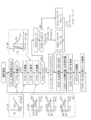
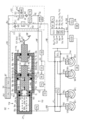
- 1 is an overall configuration diagram for explaining a first embodiment of a vehicle braking control device SC according to the present invention. It is a control flow figure for explaining the 1st example of processing of pressure regulation control including regenerative cooperation control. It is a time-series diagram for demonstrating the transition example of the braking force F corresponding to the 1st process example. It is a time series diagram for demonstrating the other transition example of the braking force F corresponding to the 1st process example. It is a whole block diagram for demonstrating 2nd Embodiment of the braking control apparatus SC of the vehicle which concerns on this invention. It is a control flow figure for explaining the 2nd processing example of pressure regulation control including regenerative cooperation control. It is a time-series diagram for demonstrating the transition example of the braking force F corresponding to the 2nd process example.
- each of the four wheel cylinders are expressed as a right front wheel wheel cylinder CWi, a left front wheel wheel cylinder CWj, a right rear wheel wheel cylinder CWk, and a left rear wheel wheel cylinder CWl.
- the suffixes “i” to “l” at the end of the symbol can be omitted.
- each symbol represents a generic name of each of the four wheels. For example, “WH” represents each wheel, and “CW” represents each wheel cylinder.
- a first embodiment of a braking control device SC according to the present invention will be described with reference to the overall configuration diagram of FIG.
- the vehicle employs two fluid paths.
- the fluid path is a path for moving the brake fluid BF, which is the working fluid of the brake control device, and corresponds to a brake pipe, a fluid unit flow path, a hose, and the like.
- the inside of the fluid path is filled with the brake fluid BF.
- the side close to the reservoir RV is referred to as “upstream side” or “upper part”
- the side close to the wheel cylinder CW is referred to as “downstream side” or “lower part”.
- front and rear type also referred to as “H type” is adopted as the two fluid paths. Specifically, it is connected to the front wheel system connected to the front wheel cylinders CWi, CWj (also referred to as “front wheel cylinder CWf”) and to the rear wheel cylinders CWk, CWl (also referred to as “rear wheel cylinder CWr”).
- front wheel cylinders CWi, CWj also referred to as “front wheel cylinder CWf”
- rear wheel cylinders CWk, CWl also referred to as “rear wheel cylinder CWr”.
- rear wheel system a two-system fluid path is configured.
- the vehicle is a hybrid vehicle or an electric vehicle, and is provided with an electric motor GN for driving.
- the electric motor GN for driving also functions as a generator (generator) for energy regeneration.
- the generator GN is provided in the front wheel WHf.
- the vehicle also includes a distance sensor OB (in order to detect a distance (relative distance) Ob between the vehicle (another vehicle, a fixed object, a person, a bicycle, etc.) existing in front of the vehicle and the vehicle.
- a camera, a radar, etc. are provided.
- the relative distance Ob is input to the driving support controller ECJ, and the required deceleration Gd is calculated based on the relative distance Ob.
- the required deceleration Gd is a target value of vehicle deceleration for automatically braking on behalf of the driver without colliding with an object in front of the vehicle.
- regenerative cooperative control cooperation between regenerative braking and friction braking
- the regenerative cooperative control is executed not only during braking by the driver but also during automatic braking by the driving support controller ECJ.
- the vehicle includes a braking operation member BP, a wheel cylinder CW, a reservoir RV, and a wheel speed sensor VW.
- Brake operation member (for example, brake pedal) BP is a member that the driver operates to decelerate the vehicle.
- the braking operation member BP By operating the braking operation member BP, the braking torque of the wheel WH is adjusted, and a braking force F (generic name of front wheel, rear wheel braking force Ff, Fr) is generated on the wheel WH.
- a rotating member for example, a brake disk
- a brake caliper is disposed so as to sandwich the rotating member.
- the brake caliper is provided with a wheel cylinder CW, and the friction member (for example, a brake pad) is pressed against the rotating member KT by increasing the pressure (braking fluid pressure) Pw of the brake fluid BF therein.
- the friction force generated at this time generates friction braking torques (also simply referred to as “torque”) Tqf and Tqr on the front and rear wheels WHf and WHr of the vehicle, resulting in friction braking forces Fmf and Fmr.
- torque also simply referred to as “torque”
- Fmf and Fmr are generated by the front and rear wheel torques Tqf and Tqr that are adjusted according to the front and rear wheel braking hydraulic pressures Pwf and Prw.
- RV is a tank for working fluid, in which braking fluid BF is stored.
- Each wheel WH of the vehicle is provided with a wheel speed sensor VW so as to detect the wheel speed Vw.
- the wheel speed Vw signal is used for independent braking control such as anti-skid control.
- a vehicle body speed Vx is calculated based on each wheel speed Vw detected by the wheel speed sensor VW.
- the braking control device SC includes an upper fluid unit YU (corresponding to an “actuator”) and a lower fluid unit YL.
- the inside of each fluid unit YU, YL is made liquid-tight by the brake fluid BF.
- the upper fluid unit YU is controlled by the upper controller ECU, and the lower fluid unit YL is controlled by the lower controller ECL.
- the upper controller ECU and the lower controller ECL are connected via a communication bus BS so that each signal (sensor detection value, calculation value, etc.) is shared.
- the upper fluid unit YU of the braking control device SC is composed of an operation amount sensor BA, an operation switch ST, a simulator SS, a master unit YM, a pressure adjustment unit YC, and a regeneration coordination unit YK.
- the front fluid braking torque Tqf and the rear wheel braking torque Tqr are individually adjusted (controlled) by the upper fluid unit YU (actuator).
- An operation amount sensor BA is provided so as to detect the operation amount Ba of the braking operation member (brake pedal) BP by the driver.
- an operation displacement sensor SP for detecting an operation displacement Sp of the braking operation member BP is provided.
- An operation force sensor FP is provided so as to detect the operation force Fp of the braking operation member BP.
- a simulator hydraulic pressure sensor PS is provided as the operation amount sensor BA so as to detect the hydraulic pressure (simulator hydraulic pressure) Ps in the simulator SS.
- An input hydraulic pressure sensor PN is provided so as to detect a hydraulic pressure (input hydraulic pressure) Pn in the input chamber Rn of the regeneration cooperative unit YK.
- the operation amount sensor BA is a general term for the operation displacement sensor SP and the like, and at least one of the operation displacement Sp, the operation force Fp, the simulator fluid pressure Ps, and the input fluid pressure Pn is adopted as the braking operation amount Ba. .
- the brake operation member BP is provided with an operation switch ST so as to detect whether or not the driver has operated the brake operation member BP. When the brake operation member BP is not operated (that is, during non-braking), the brake operation switch ST outputs an off signal as the operation signal St. On the other hand, when the braking operation member BP is operated (that is, during braking), an ON signal is output as the operation signal St.
- the braking operation amount Ba and the operation signal St are input to the upper controller ECU.
- a simulator SS is provided to generate an operation force Fp on the braking operation member BP.
- a piston and an elastic body are provided inside the simulator SS.
- the piston is pushed by the flowing braking fluid BF.
- a force is applied to the piston in the direction of blocking the inflow of the brake fluid BF by the elastic body, so that an operation force Fp when the brake operation member BP is operated is formed.
- the master unit YM adjusts the hydraulic pressure (front wheel braking hydraulic pressure) Pwf in the front wheel cylinder CWf via the master cylinder chamber Rm.
- the master unit YM includes a master cylinder CM, a master piston PM, and a master elastic body SM.
- the master cylinder CM is a cylinder member having a bottom.
- the master piston PM is a piston member inserted into the master cylinder CM, and is movable in conjunction with the operation of the braking operation member BP.
- the interior of the master cylinder CM is divided into three hydraulic chambers Rm, Rs, and Ro by the master piston PM.
- the first inner peripheral portion Mw of the master cylinder CM and the outer peripheral portion (outer peripheral cylindrical surface) Mp of the master piston PM are sealed (sealed) by the two seals SL.
- the master cylinder chamber (also simply referred to as “master chamber”) Rm is defined by “the first inner peripheral portion Mw and the first bottom portion (bottom surface) Mu of the master cylinder CM” and the first end portion Mv of the master piston PM. It is a partitioned hydraulic chamber.
- a master cylinder fluid path HM is connected to the master chamber Rm.
- the master piston PM is provided with a flange portion (flange) Tm.
- the inside of the master cylinder CM is divided into a servo hydraulic chamber (simply referred to as “servo chamber”) Rs and a rear hydraulic chamber (simply referred to as “rear chamber”) Ro by the collar portion Tm.
- a seal SL is provided on the outer peripheral portion of the collar portion Tm, and the collar portion Tm and the second inner peripheral portion Md of the master cylinder CM are sealed.
- the servo chamber Rs is a hydraulic chamber defined by “the second inner peripheral portion Md of the master cylinder CM, the second bottom portion (bottom surface) Mt” and the first surface Ms of the flange portion Tm of the master piston PM.
- the master chamber Rm and the servo chamber Rs are arranged to face each other with the master piston PM (particularly, the collar portion Tm) interposed therebetween.
- the rear chamber Ro is a hydraulic chamber defined by the second inner peripheral portion Md of the master cylinder CM, the stepped portion Mz, and the second surface Mo of the collar portion Tm of the master piston PM.
- the rear chamber Ro is sandwiched between the master chamber Rm and the servo chamber Rs in the direction of the central axis Jm, and is located between them.
- a pressure adjusting fluid path HC is connected to the servo chamber Rs, and a simulator fluid path HS is connected to the rear chamber Ro.
- a master elastic body (for example, a compression spring) SM is provided between the recess Mx of the first end Mv of the master piston PM and the first bottom Mu of the master cylinder CM.
- the master elastic body SM presses the master piston PM against the second bottom Mt of the master cylinder CM in the direction of the central axis Jm of the master cylinder CM.
- the stepped portion My of the master piston PM is in contact with the second bottom portion Mt of the master cylinder CM.
- the position of the master piston PM in this state is referred to as “initial position of the master unit YM”.
- the connection between the master chamber Rm and the reservoir RV is cut off, and the pressure (“master cylinder hydraulic pressure” is applied to the master chamber Rm. Pm) is also generated.
- the urging force Fb (referred to as “retraction force”) in the retreat direction Hb along the central axis Jm is applied to the master piston PM by the master hydraulic pressure Pm.
- the servo chamber Rs applies an urging force Fa (referred to as “forward force”) opposite to the retreating force Fb to the master piston PM by its internal pressure.
- a master hydraulic pressure sensor PQ is provided so as to detect the master hydraulic pressure Pm.
- the master hydraulic pressure sensor PQ may be included in the lower fluid unit YL.
- the pressure adjusting unit YC adjusts the hydraulic pressure Pwf of the front wheel cylinder CWf (resulting in front wheel torque Tqf) and the hydraulic pressure Pwr of the rear wheel wheel cylinder CWr (rear wheel torque Tqr) independently and individually. . Specifically, the brake hydraulic pressure Pwf of the front wheel WHf is individually adjusted to be equal to or lower than the brake hydraulic pressure Pwr of the rear wheel WHr.
- the pressure adjustment unit YC includes an electric pump DC, a check valve GC, first and second pressure adjustment valves UB and UC, and first and second adjustment hydraulic pressure sensors PB and PC.
- the electric motor MC and the fluid pump QC are fixed so that the electric motor MC and the fluid pump QC rotate together.
- the electric pump DC (in particular, the electric motor MC) is a power source for increasing the brake fluid pressure Pw during control braking.
- the electric motor MC is controlled by the controller ECU.
- a three-phase brushless motor is employed as the electric motor MC.
- the suction port Qs of the fluid pump QC is connected to the reservoir RV via the first reservoir fluid path HV.
- a pressure regulating fluid path HC is connected to the discharge port Qt of the fluid pump QC.
- the brake fluid BF is sucked from the first reservoir fluid path HV through the suction port Qs and discharged from the discharge port Qt to the pressure regulating fluid path HC.
- a gear pump is employed as the fluid pump QC.
- a check valve GC (also referred to as “check valve”) is interposed in the pressure regulating fluid path HC.
- Two normally open pressure regulating valves UB and UC are provided in series in the pressure regulating fluid path HC.
- the first pressure regulating valve UB is provided in the pressure regulating fluid path HC.
- the 2nd pressure regulation valve UC is arrange
- the first and second pressure regulating valves UB, UC are linear solenoid valves (“proportional valves”, or the like, in which the valve opening amount (lift amount) is continuously controlled based on the energized state (for example, supply current), or Also called “differential pressure valve”.
- the first and second pressure regulating valves UB and UC are controlled by the controller ECU based on the drive signals Ub and Uc.
- the brake fluid BF is pumped up from the first reservoir fluid passage HV by the fluid pump QC, passes through the first pressure regulating valve UB and the second pressure regulating valve UC, and returned to the reservoir fluid passage HV.
- the first reservoir fluid path HV and the pressure regulating fluid path HC form a reflux path (a fluid path in which the flow of the brake fluid BF returns to the original flow).
- the second pressure regulating valves UB and UC are provided in series.
- the hydraulic pressure (first pressure) between the first pressure regulating valve UB and the second pressure regulating valve UC in the pressure regulating fluid path HC. 2 adjustment hydraulic pressure) Pc is increased from “0”. Since the first and second pressure regulating valves UB and UC are arranged in series in the pressure regulating fluid path HC, the second adjustment hydraulic pressure Pc adjusted by the second pressure regulating valve UC is equal to or lower than the first adjustment hydraulic pressure Pb. .
- First and second adjustment hydraulic pressure sensors PB and PC are provided in the pressure adjustment fluid path HC so as to detect the first and second adjustment hydraulic pressures Pb and Pc.
- the pressure regulating fluid path HC is branched to the rear wheel regulating fluid path HR at a portion Bh between the fluid pump QC and the first pressure regulating valve UB.
- the rear wheel pressure adjusting fluid path HR is connected to the rear wheel wheel cylinder CWr via the lower fluid unit YL. Accordingly, the first adjustment hydraulic pressure Pb is directly introduced (supplied) to the rear wheel hole cylinder CWr.
- the pressure regulating fluid path HC is branched to the front wheel pressure regulating fluid path HF at a portion Bg between the first pressure regulating valve UB and the second pressure regulating valve UC.
- the front wheel pressure adjusting fluid path HF is connected to the servo chamber Rs.
- the second adjustment hydraulic pressure Pc is introduced (supplied) into the servo chamber Rs. Since the master cylinder CM is connected to the front wheel cylinder CWf via the lower fluid unit YL, the second adjustment hydraulic pressure Pc is indirectly introduced to the front wheel cylinder CWf via the master cylinder CM.
- the pressure regulating unit YC is provided with a bypass fluid path HD that connects the reservoir RV and the servo chamber Rs in parallel with the pressure regulating fluid path HC.
- a check valve GD is interposed in the fluid path HD. In the check valve GD, the flow of the brake fluid BF from the reservoir RV to the servo chamber Rs is allowed, but the flow from the servo chamber Rs to the reservoir RV is blocked.
- the master piston PM can be moved in the forward direction Ha and the volume of the servo chamber Rs can be increased also by the operation force of the driver. In this case, the amount of liquid corresponding to the volume increase of the servo chamber Rs caused by the operation of the driver is supplied via the bypass fluid path HD and the check valve GD. Since the amount of the brake fluid BF supplied by the electric pump DC is efficiently used to increase the brake fluid pressure Pw, the boosting response during sudden braking can be improved.
- the regenerative cooperative unit YK achieves cooperative control of friction braking and regenerative braking (referred to as “regenerative cooperative control”). That is, a state in which the braking operation member BP is operated by the regenerative cooperation unit YK but the braking hydraulic pressure Pw is not generated can be formed.
- the regenerative cooperative unit YK includes an input cylinder CN, an input piston PK, an input elastic body SN, a first on-off valve VA, a second on-off valve VB, a simulator SS, a simulator hydraulic pressure sensor PS, and an input hydraulic pressure sensor PN. Is done.
- the input cylinder CN is a cylinder member having a bottom portion fixed to the master cylinder CM.
- the input piston PK is a piston member inserted into the input cylinder CN.
- the input piston PK is mechanically connected to the braking operation member BP.
- the input piston PK is provided with a flange portion (flange) Tn.
- An input elastic body SN is provided between the attachment surface Ma of the input cylinder CN to the master cylinder CM and the flange portion Tn of the input piston PK. The input elastic body SN presses the flange portion Tn of the input piston PK against the bottom Mb of the input cylinder CN in the direction of the central axis Jm.
- the stepped portion My of the master piston PM is in contact with the second bottom portion Mt of the master cylinder CM, and the collar portion Tn of the input piston PK is in contact with the bottom portion Mb of the input cylinder CN.
- the gap Ks between the master piston PM (particularly the end face Mq) and the input piston PK (particularly the end face Mg) is set to a predetermined distance ks (referred to as “initial gap”) inside the input cylinder CN. Yes.
- the master piston PM and the input piston PK are separated by a predetermined distance ks.
- the predetermined distance ks corresponds to the maximum value of the regeneration amount Rg.
- the input cylinder CN is connected to the reservoir RV via the second reservoir fluid path HT.
- a portion of the second reservoir fluid path HT can be shared with the first reservoir fluid path HV.
- two on-off valves VA and VB are provided in series.
- the first and second on-off valves VA and VB are two-position solenoid valves (also referred to as “on / off valves”) having an open position (communication state) and a closed position (blocking state).
- the first and second on-off valves VA and VB are controlled by the upper controller ECU based on the drive signals Va and Vb.
- a normally closed solenoid valve is employed as the first on-off valve VA
- a normally open solenoid valve is employed as the second on-off valve VB.
- the second reservoir fluid passage HT is connected to the simulator fluid passage HS at a connection portion Bs between the first on-off valve VA and the second on-off valve VB.
- one end of the simulator fluid path HS is connected to the rear chamber Ro, and the other end is connected to the part Bs.
- a simulator SS is provided in the simulator fluid path HS.
- a simulator hydraulic pressure sensor PS is provided so as to detect the hydraulic pressure (simulator hydraulic pressure) Ps in the simulator SS. Further, the input hydraulic pressure is detected so as to detect the hydraulic pressure Pn between the first on-off valve VA of the second reservoir fluid path HT and the input chamber Rn (which is the hydraulic pressure of the input chamber Rn and is referred to as “input hydraulic pressure”).
- a sensor PN is provided.
- the simulator hydraulic pressure sensor PS and the input hydraulic pressure sensor PN are one of the braking operation amount sensors BA described above.
- the detected hydraulic pressures Ps and Pn are input to the upper controller ECU as a braking operation amount Ba.
- the electric motor MC and the electromagnetic valves VA, VB, UB, UC are controlled by the upper controller ECU. Specifically, the upper controller ECU calculates drive signals Va, Vb, Ub, Uc for controlling various electromagnetic valves VA, VB, UB, UC. Similarly, a drive signal Mc for controlling the electric motor MC is calculated. Then, based on the drive signals Va, Vb, Ua, Ub, Mc, the solenoid valves VA, VB, UB, UC and the electric motor MC are driven.
- the upper controller (electronic control unit) ECU is connected to the lower controller ECL and other system controllers (ECD, ECJ, etc.) via the in-vehicle communication bus BS.
- a regeneration amount (target value) Rg is transmitted from the upper controller ECU to the drive controller ECD through the communication bus BS so as to execute the regeneration cooperative control.
- the required deceleration (target value) Gd is transmitted from the driving support controller ECJ to the upper controller ECU through the communication bus BS.
- the lower fluid unit YL is a known fluid unit including a master hydraulic pressure sensor PQ, a plurality of solenoid valves, an electric pump, and a low pressure reservoir.
- the lower fluid unit YL is controlled by the lower controller ECL.
- the vehicle body speed Vx is calculated based on the wheel speed Vw.
- anti-skid control is executed so as to suppress excessive deceleration slip (for example, wheel lock) of the wheel WH.
- the brake fluid pressure Pw of each wheel WH is individually controlled by the lower fluid unit YL.
- the calculated vehicle speed Vx is input to the upper controller ECU through the communication bus BS.
- the input chamber Rn and the rear chamber Ro are connected by the open position of the first on-off valve VA, and the simulator SS is connected to the input chamber Rn. Is done. Further, the connection between the simulator SS and the reservoir RV is cut off by the closed position of the second on-off valve VB.
- the input piston PK is moved in the forward direction Ha by the operation of the braking operation member BP, and the amount of liquid flowing out from the input chamber Rn by the movement flows into the simulator SS, and the operation force Fp of the braking operation member BP is formed.
- the controller ECU controls the pressure adjustment unit YC and adjusts the first and second adjustment hydraulic pressures Pb and Pc.
- the first adjustment hydraulic pressure Pb is directly applied to the rear wheel wheel cylinder CWr through the rear wheel pressure adjusting fluid path HR and the lower fluid unit YL.
- the second adjustment hydraulic pressure Pc is applied to the servo chamber Rs through the front wheel pressure adjusting fluid passage HF.
- the master chamber Rm is blocked from the reservoir RV by the movement in the forward direction Ha. Further, when the second adjustment hydraulic pressure Pc is increased, the brake fluid BF is pumped from the master cylinder CM toward the front wheel cylinder CWf at the master hydraulic pressure Pm. A force (retracting force) Fb in the retreating direction Hb is applied to the master piston PM by the master hydraulic pressure Pm. The servo chamber Rs generates a force (forward force) Fa in the forward direction Ha by the second adjustment hydraulic pressure Pc so as to oppose (oppose) the backward force Fb. The master hydraulic pressure Pm is increased or decreased according to the increase or decrease of the adjustment hydraulic pressure Pc.
- the gap Ks can be adjusted independently of the braking operation amount Ba within the range of “0 ⁇ Ks ⁇ ks” by the second adjustment hydraulic pressure Pc. That is, by adjusting the second adjustment hydraulic pressure Pc, the gap Ks is adjusted, and regenerative cooperative control is achieved.
- the second adjustment hydraulic pressure Pc is decreased by the pressure adjustment unit YC.
- the master piston PM is moved in the backward direction Hb.
- the braking operation member BP is brought into a non-operating state
- the master piston PM comes into contact with the second bottom portion Mt of the master cylinder CM (initial position) by the elastic force of the compression spring SM. It is returned to.
- Pressure adjustment control is drive control of the electric motor MC and the first and second pressure adjustment valves UB and UC for adjusting the first and second adjustment hydraulic pressures Pb and Pc.
- the control algorithm is programmed in the upper controller ECU.
- step S110 the braking operation amount Ba, the operation signal St, the first and second adjustment hydraulic pressures (detected values) Pb and Pc, the required deceleration Gd, and the vehicle body speed Vx are read.
- the operation amount Ba is detected by an operation amount sensor BA (operation displacement sensor SP, operation force sensor FP, input hydraulic pressure sensor PN, simulator hydraulic pressure sensor PS, etc.).
- the operation signal St is detected by the operation switch ST.
- the first and second adjustment hydraulic pressures Pb and Pc are detected by the first and second adjustment hydraulic pressure sensors PB and PC provided in the pressure adjustment fluid path HC.
- the requested deceleration Gd due to automatic braking is acquired from the driving support controller ECJ via the communication bus BS.
- the vehicle body speed Vx is acquired from the lower controller ECL via the communication bus BS.
- the vehicle body speed Vx may be calculated by the upper controller ECU based on the wheel speed Vw when the wheel speed Vw is input to the upper controller ECU.
- step S120 based on at least one of the braking operation amount Ba and the braking operation signal St, it is determined whether or not braking is being performed. For example, when the operation amount Ba is larger than the predetermined value bo, step S120 is affirmed and the process proceeds to step S130. On the other hand, when the braking operation amount Ba is less than or equal to the predetermined value bo, Step S120 is denied and the process returns to Step S110.
- the predetermined value bo is a preset constant corresponding to the play of the braking operation member BP.
- step S120 based on the required deceleration Gd, it is determined whether or not braking is being performed. For example, when the required deceleration Gd is larger than the predetermined value go, step S120 is affirmed and the process proceeds to step S130. On the other hand, if the requested deceleration Gd is equal to or less than the predetermined value go, step S120 is denied and the process returns to step S110.
- the predetermined value go is a preset constant (for example, “0”).
- step S130 the required braking force Fd is calculated based on the operation amount Ba.
- the required braking force Fd is a target value of the total braking force F acting on the vehicle, and is a braking force obtained by combining the “friction braking force Fm by the braking controller SC” and the “regenerative braking force Fg by the generator GN”.
- the required braking force Fd is determined to be “0” when the operation amount Ba is in the range from “0” to the predetermined value bo according to the calculation map Zfd.
- the operation amount Ba increases. Accordingly, calculation is performed so as to monotonically increase from “0”.
- the required braking force Fd is calculated based on the required deceleration Gd.
- the required braking force Fd is determined to be “0” when the required deceleration Gd is equal to or greater than “0” and less than the predetermined value go, and when the required deceleration Gd is equal to or greater than the predetermined value bo, according to the increase in the required deceleration Gd, “ It is determined to monotonically increase from “0”.
- step S140 the maximum value (referred to as “maximum regenerative force”) Fx of the regenerative braking force is calculated based on the vehicle body speed Vx and the calculation map Zfx.
- the regeneration amount of the generator GN is limited by the rating of the power transistor (IGBT or the like) of the drive controller ECD and the battery charge acceptance.
- the regeneration amount of the generator GN is controlled to a predetermined power (electric energy per unit time). Since the electric power (power) is constant, the regenerative torque around the wheel shaft by the generator GN is inversely proportional to the rotation speed of the wheel WH (that is, the vehicle body speed Vx).
- the maximum regenerative force Fx increases as the vehicle body speed Vx increases in the range where the vehicle body speed Vx is greater than or equal to “0” and less than the first predetermined speed vo. Is set as follows. Further, in the range where the vehicle body speed Vx is equal to or higher than the first predetermined speed vo and lower than the second predetermined speed vp, the maximum regenerative force Fx is determined as the upper limit value fx.
- the maximum regenerative force Fx is set to decrease as the vehicle body speed Vx increases.
- the reduction characteristic of the maximum regenerative force Fx characteristic of “Vx ⁇ vp”
- the relationship between the vehicle body speed Vx and the maximum regenerative force Fx is represented by a hyperbola (that is, the regenerative power is constant).
- the predetermined values vo and vp are preset constants. Note that in the calculation map Zfx, the rotational speed Ng of the generator GN can be adopted instead of the vehicle body speed Vx.
- the rear wheel ratio Hr (corresponding to “front / rear ratio”) is based on at least one of the turning state amount Ta, the vehicle body speed Vx, and the required braking force Fd. Calculated.
- the rear wheel ratio Hr can be determined as a preset constant hr.
- the rear wheel ratio Hr is a value representing the distribution ratio of the braking force between the front and rear wheels.
- the rear wheel ratio Hr is calculated based on the turning state amount Ta.
- the turning state amount Ta is a state amount representing the degree of turning of the vehicle.
- the vehicle includes a steering angle sensor SA, a yaw rate sensor YR, and a lateral acceleration sensor GY, which are generally referred to as a “turning state sensor TA”.
- the steering angle Sa is detected by the steering angle sensor SA
- the yaw rate Yr is detected by the yaw rate sensor YR
- the lateral acceleration Gy is detected by the lateral acceleration sensor GY.
- the rear wheel ratio Hr is calculated so as to decrease as the turning state amount Ta increases according to the calculation map Zhr. As a result, the larger the turning state amount Ta, the smaller the rear wheel braking force Fr, and the lateral force of the rear wheel WHr is ensured, so that the turning stability of the vehicle can be improved.
- the rear wheel ratio Hr is provided with a lower limit value ha and an upper limit value hb.
- the rear wheel ratio Hr (front / rear ratio) is calculated based on the vehicle speed Vx.
- the rear wheel ratio Hr is calculated so as to decrease as the vehicle body speed Vx increases according to the calculation map Yhr.
- the rear wheel ratio Hr is provided with a lower limit value ia and an upper limit value ib.
- the rear wheel ratio Hr is calculated based on the required braking force Fd.
- the rear wheel ratio Hr is calculated so as to decrease as the required braking force Fd increases in accordance with the calculation map Xhr.
- the rear wheel ratio Hr is provided with a lower limit value ja and an upper limit value jb.
- the longitudinal acceleration (deceleration) Gx detected by the longitudinal acceleration sensor GX provided in the vehicle may be employed. That is, the rear wheel ratio Hr is calculated based on the degree of deceleration of the vehicle so that the rear wheel ratio Hr decreases as the degree increases.
- step S160 based on the required braking force Fd and the maximum regenerative force Fx, it is determined whether or not the required brake force Fd is equal to or less than the maximum regenerative force Fx. That is, it is determined whether or not the braking force Fd requested by the driver can be achieved only by the regenerative braking force. If “Fd ⁇ Fx” and step S160 is positive, the process proceeds to step S170. On the other hand, if “Fd> Fx” and step S160 is negative, the process proceeds to step S180.
- the rear wheel reference force Fs is calculated based on the required braking force Fd.
- the rear wheel reference force Fs is a value in which the front / rear ratio of the braking force (that is, the rear wheel ratio Hr) is considered with respect to the required braking force Fd, and is used as a reference for achieving the rear wheel ratio Hr.
- the complementary braking force Fh is calculated based on the required braking force Fd and the maximum regenerative force Fx.
- the complementary braking force Fh is less than or equal to the rear wheel reference force Fs
- the front wheel friction braking force Fmf is not generated and only the regenerative braking force Fg is applied to the front wheel WHf.
- the friction braking force Fmr is generated at the rear wheel WHr so that the required braking force Fd is satisfied.
- the complementary braking force Fh is greater than the rear wheel reference force Fs
- step S220 the regenerative amount Rg is calculated based on the regenerative braking force Fg.
- the regeneration amount Rg is a target value for the regeneration amount of the generator GN.
- the regeneration amount Rg is transmitted from the braking controller ECU to the drive controller ECD via the communication bus BS.
- the first on-off valve VA is driven to the open position, and the second on-off valve VB is driven to the closed position.
- the target hydraulic pressure Pt (Ptf, Ptr) is calculated based on the target value Fm (Fmf, Fmr) of the friction braking force. That is, the friction braking force Fm is converted into a hydraulic pressure, and the target hydraulic pressure Pt is determined.
- the rear wheel target hydraulic pressure Ptr is a target value of the hydraulic pressure of the rear wheel wheel cylinder CWr corresponding to the first adjustment hydraulic pressure Pb.
- the front wheel target hydraulic pressure Ptf is a target value of the hydraulic pressure of the front wheel cylinder CWf corresponding to the second adjustment hydraulic pressure Pc.
- step S250 the electric motor MC is driven to form a reflux of the brake fluid BF including the fluid pump QC.
- step S260 based on the rear wheel target fluid pressure Ptr and the first adjustment fluid pressure Pb (detected value of the first adjustment fluid pressure sensor PB), the first adjustment fluid pressure Pb is changed to the rear wheel target fluid.
- the first pressure regulating valve UB is servo-controlled so as to match the pressure Ptr.
- the second adjustment hydraulic pressure Pc is matched with the front wheel target hydraulic pressure Ptf.
- the second pressure regulating valve UC is servo controlled. In the servo control, feedback control is performed so that the actual values Pb and Pc coincide with the target value Pt.
- the first and second pressure regulating valves UB and UC are arranged in series with the pressure regulating fluid path HC. For this reason, in the hydraulic pressure feedback control of the first and second adjustment hydraulic pressures Pb and Pc, they affect each other, and so-called control interference can occur. In such a case, the control of the second adjustment hydraulic pressure Pc related to the front wheel WHf has priority over the control of the first adjustment hydraulic pressure Pb related to the rear wheel WHr.
- the front wheel braking force Ff is based on a higher contribution to the total braking force F than the rear wheel braking force Fr.
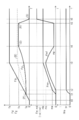
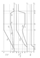
- a transition example of the braking force F corresponding to the first processing example will be described with reference to the time series diagram of FIG.
- the regenerative generator GN is provided on the front wheel WHf, and the regenerative braking force Fg acts on the front wheel WHf in addition to the friction braking force Fmf.
- the generator GN is not provided in the rear wheel WHr. For this reason, the regenerative braking force does not act on the rear wheel WHr, and only the friction braking force Fmr acts.
- the component due to the regenerative braking force Fg is “a portion sandwiched by the curve PQRS indicating the X axis and the regenerative braking force Fg”
- the component due to the front wheel friction braking force Fmf is “
- the component of the rear wheel friction braking force Fmr corresponds to “the portion sandwiched between the required braking force Fd and the two-dot chain line (B)”, respectively, to “the portion sandwiched between the two-dot chain line (B) and the curve PQRS”.
- the friction braking force Fm is not generated, and the vehicle is decelerated only by the regenerative braking force Fg. That is, when the regenerative braking force Fg by the regenerative generator GN has not reached the maximum regenerative force Fx that can be generated (that is, when “Fg ⁇ Fx”), the front wheel torque Tqf and the rear wheel torque Tqr are “ 0 (zero) ". At this time, the actual rear wheel ratio Hra is “0”.
- the rear wheel braking hydraulic pressure Pwr is rapidly increased (that is, the front wheel torque Tqf is “0” and the rear wheel torque Tqr is rapidly increased). That is, when the regenerative braking force Fg reaches the maximum regenerative force Fx, the rear wheel torque Tqr is increased from “0” before the front wheel torque Tqf is increased from “0”, and the required braking force Fd is increased. The minute is supplemented only by the rear wheel torque Tqr. Therefore, the actual rear wheel ratio Hra is quickly changed from “0” toward the set value (constant) hr.
- the increase of the front wheel torque Tqf is started, and the increase gradient of the rear wheel torque Tqr (rear wheel friction braking force Fmr) is decreased from the state of “Fh ⁇ Fs”, and the increase is continued.
- the vehicle body speed Vx that is, the rotational speed Ng of the generator GN
- the maximum regenerative force Fx is increased, and the regenerative braking force Fg is increased accordingly (see the characteristic Zfx of the block X140).
- the front wheel braking fluid pressure Pwf ie, front wheel torque Tqf
- the rear wheel braking fluid pressure Pwr ie, rear wheel torque Tqr
- the rear wheel ratio Hra (including the regenerative braking force Fg) can be suitably maintained at the target set value hr.
- the vehicle body speed Vx reaches the predetermined speed vo, and the maximum regenerative force Fx decreases. That is, the switching operation between regenerative braking and friction braking is started at time t5.
- the rear wheel friction braking force Fmr is made constant, and the decrease in the regenerative braking force Fg is compensated by the front wheel friction braking force Fmf.
- the rear wheel friction braking force Fmr is held constant, and the fluctuation of the regenerative braking force Fg is adjusted by the front wheel friction braking force Fmf. Therefore, the rear wheel ratio (actual value) Hra including the regenerative braking force Fg can be maintained at the target value hr.
- the front wheel and rear wheel torques Tqf and Tqr are set to “0”, and no friction braking force is generated, so that the energy regeneration by the generator GN is maximized. Can be done. If the required braking force Fd cannot be achieved only by the regenerative braking force Fg, the rear wheel torque Tqr is maintained at “0”, and the rear wheel torque Tqr is the rear wheel reference force in which the front / rear distribution ratio of the braking force is considered. It is increased to a value according to Fs. For this reason, the desired distribution ratio hr can be achieved quickly. After the target distribution ratio hr is achieved, the front wheel torque Tqf is increased, the increase gradient of the rear wheel torque Tqr is decreased, and the rear wheel torque Tqr is increased. For this reason, the target ratio hr can be suitably maintained.
- the operation amount Ba is made constant. From the time point u3, the front wheel friction braking force Fmf is maintained at a constant value mg, but the front wheel friction braking force Fmf is decreased to compensate for the increase in the regenerative braking force Fg.
- the vehicle body speed Vx reaches the predetermined speed vo, the maximum regenerative force Fx starts to decrease, and the switching operation between regenerative braking and friction braking is started.
- the rear wheel friction braking force Fmr is increased and returned to the value mg.
- the rear wheel friction braking force Fmr is made constant, and the front wheel friction braking force Fmf is increased.
- a decrease in the regenerative braking force Fg is compensated.
- transition examples also have the same effect (maximization of energy regeneration, rapid achievement of desired ratio and reliable continuation).
- the regenerative braking force Fg is increased as the vehicle decelerates, the front wheel torque Tqf is set to “0” and the rear wheel torque Tqr is decreased from a value corresponding to the rear wheel reference force Fs. . Therefore, the required braking force Fd corresponding to the braking operation amount Ba (that is, the vehicle deceleration required by the driver) can be achieved while maximizing energy regeneration.
- the rear wheel ratio Hra is reduced from the desired ratio hr, the vehicle speed Vx is low, so the influence on the vehicle stability is negligible.
- the front wheel friction braking force Fmf is increased after the rear wheel torque Tqr is increased.
- the rear wheel ratio Hra can be maintained at the desired ratio hr.
- the front wheel and rear wheel torques Tqf and Tqr can be increased simultaneously by the switching operation.
- only the front wheel torque Tqf may be increased while the rear wheel torque Tqr is reduced.
- the rear wheel friction braking force Fmr (rear wheel torque Tqr) is decreased and adjusted so as to satisfy the required braking force Fd between the time point u4 and the time point u6.
- the regenerative braking force Fg may be adjusted. In this case, as indicated by a broken line, the regenerative braking force Fg is reduced from the maximum regenerative force Fx (that is, the upper limit value fx) while the rear wheel friction braking force Fmr is maintained at the value mg.
- the rear wheel ratio Hra can always be maintained at a desired distribution ratio hr.
- a second embodiment of the braking control device SC according to the present invention will be described with reference to the overall configuration diagram of FIG.
- the generator GN is provided on the front wheels WHf (WHi, WHj).
- the generator GN is provided on the rear wheel WHr (WHk, WHl).
- each symbol represents a generic name of each of the four wheels.
- Subscripts “f” and “r” at the end of the symbol are general symbols indicating which of the front and rear wheels the two fluid paths (movement paths of the brake fluid BF) relate to.
- two pressure regulating valves UB and UC are provided in series in the pressure regulating fluid path HC.
- the first pressure regulating valve UB and the second pressure regulating valve UC are arranged in this order along the circulation flow (A) of the brake fluid BF.
- the second pressure adjustment valve UC adjusts the second adjustment hydraulic pressure Pc to increase from “0 (atmospheric pressure)”
- the first pressure adjustment valve UB changes the first adjustment hydraulic pressure Pb from the second adjustment hydraulic pressure Pc. Adjusted to increase.
- the first adjustment hydraulic pressure Pb is adjusted to the first adjustment hydraulic pressure Pb
- the second adjustment hydraulic pressure UC is adjusted to decrease the second adjustment hydraulic pressure Pc from the first adjustment hydraulic pressure Pb. That is, the first adjustment hydraulic pressure Pb and the second adjustment hydraulic pressure Pc have a relationship of “Pb ⁇ Pc”.
- the hydraulic pressure Pwf of the front wheel wheel cylinder CWf and the hydraulic pressure Pwr of the rear wheel wheel cylinder CWr are adjusted independently. Then, the hydraulic pressure Pwr of the rear wheel WHr provided with the generator GN is adjusted to be equal to or lower than the braking hydraulic pressure Pwf of the front wheel WHf not provided with the generator GN.
- the pressure regulating fluid path HC is branched to the front wheel regulating fluid path HF at a portion Cg between the fluid pump QC and the first pressure regulating valve UB.
- the front wheel pressure adjusting fluid passage HF is connected to the servo chamber Rs, and the first adjustment hydraulic pressure Pb is introduced (supplied) to the servo chamber Rs.
- the first adjustment hydraulic pressure Pb is indirectly introduced into the front wheel cylinder CWf via the master cylinder CM. That is, the first adjustment hydraulic pressure Pb is supplied to the front wheel cylinder CWf in the order of “Rs ⁇ Rm ⁇ CWf”. Further, the pressure regulating fluid path HC is branched to the rear wheel pressure regulating fluid path HR at a portion Cs between the first pressure regulating valve UB and the second pressure regulating valve UC. The rear wheel pressure adjusting fluid path HR is connected to the rear wheel wheel cylinder CWr via the lower fluid unit YL.
- the second adjustment hydraulic pressure Pc is directly introduced (supplied) to the rear wheel hole cylinder CWr and is adjusted in a range of “0 ⁇ Pc ⁇ Pb”.
- the pressure adjustment unit YC includes first and second electromagnetic valves UB and UC.
- the brake fluid BF discharged from the electric pump DC is adjusted to the first adjustment hydraulic pressure Pb by the first pressure adjustment valve UB.
- the first adjustment hydraulic pressure Pb is introduced into the servo chamber Rs.
- the first adjustment hydraulic pressure Pb is reduced and adjusted to the second adjustment hydraulic pressure Pc by the second pressure regulating valve UC, and the second adjustment hydraulic pressure Pc is introduced into the rear wheel wheel cylinder CWr.
- the gap (separation displacement) Ks is adjusted, and regenerative cooperative control is achieved.
- Steps S310 to S340 are the same as the processes of steps S110 to S140.
- step S310 various signals (Ba, St, Pb, Pc, Gd, Vx, etc.) are read.
- step S320 “whether or not braking is being performed” is determined based on at least one of the braking operation amount Ba, the braking operation signal St, and the required deceleration Gd. The process proceeds to step S330 during braking, but returns to step S310 during non-braking.
- the required braking force Fd is calculated based on the calculation map Zfd shown in block X330 (same as block X130).
- the required braking force Fd is a target value of the entire braking force F to be applied to the vehicle in response to an operation of the braking operation member BP or automatic braking.
- the maximum regenerative force Fx is calculated based on the calculation map Zfx shown in the block X340 (same as the block X140).
- the maximum regenerative force Fx is the maximum value of the regenerative braking force Fg that can be generated by the generator GN.
- the front wheel ratio Hf (corresponding to “front / rear ratio”) is at least one of the turning state amount Ta, the vehicle body speed Vx, and the required braking force Fd. It is calculated based on one.
- the front wheel ratio Hf is determined as a preset constant hf.
- the front wheel ratio Hf is a value (target value) representing a distribution ratio of the braking force between the front and rear wheels.
- the front wheel ratio Hf is calculated based on the turning state amount Ta (at least one of the steering angle Sa, the yaw rate Yr, and the lateral acceleration Gy).
- the front wheel ratio Hf is calculated so as to increase as the turning state amount Ta increases according to the calculation map Zhf.
- the front wheel ratio Hf is provided with a lower limit value ha and an upper limit value hb.
- the front wheel ratio (front / rear ratio) Hf is calculated based on the vehicle body speed Vx.
- the front wheel ratio Hf is calculated so as to increase as the vehicle body speed Vx increases in accordance with the calculation map Yhf.
- the front wheel ratio Hf is provided with a lower limit value ia and an upper limit value ib.
- the front wheel ratio Hf is calculated based on the required braking force Fd.
- the front wheel ratio Hf is calculated so as to increase as the required braking force Fd increases in accordance with the calculation map Xhf.
- the front wheel ratio Hf is provided with a lower limit value ja and an upper limit value jb.
- longitudinal acceleration (deceleration) Gx may be employed. That is, the front wheel ratio Hf is calculated based on the degree of deceleration of the vehicle so that the front wheel ratio Hf increases as the degree increases.
- Steps S360 to S380 are the same as the processes of steps S160 to S180.
- step S360 based on the required braking force Fd and the maximum regenerative force Fx, it is determined whether or not the required brake force Fd is equal to or less than the maximum regenerative force Fx. In the case of “Fd ⁇ Fx”, the process proceeds to step S370. On the other hand, if “Fd> Fx”, the process proceeds to step S380.
- the front wheel reference force Ft is calculated based on the required braking force Fd.
- the front wheel reference force Ft is a value in which the front / rear ratio of the braking force (that is, the front wheel ratio Hf) is considered with respect to the required braking force Fd, and is used as a reference when the front wheel ratio Hf is achieved.
- a complementary braking force Fh is calculated based on the regenerative force Fx, which is a braking force to be supplemented by friction braking in order to achieve the required braking force Fd.
- the complementary braking force Fh is less than or equal to the front wheel reference force Ft, the rear wheel friction braking force Fmr is not generated on the rear wheel WHr, and only the regenerative braking force Fg is applied.
- step S420 the regenerative amount Rg (target value) is calculated based on the regenerative braking force Fg, and transmitted to the drive controller ECD via the communication bus BS.
- step S430 the first on-off valve VA is driven to the open position, and the second on-off valve VB is driven to the closed position.
- step S440 target hydraulic pressures Ptf and Ptr are calculated based on the target values Fmf and Fmr of the friction braking force.
- the front wheel target hydraulic pressure Ptf is a target value of the hydraulic pressure of the front wheel cylinder CWf corresponding to the first adjustment hydraulic pressure Pb.
- the rear wheel target hydraulic pressure Ptr is a target value of the hydraulic pressure of the rear wheel wheel cylinder CWr corresponding to the second adjustment hydraulic pressure Pc.
- step S450 the electric motor MC is driven to form a reflux of the brake fluid BF including the fluid pump QC.
- step S460 based on the front wheel target hydraulic pressure Ptf and the first adjusted hydraulic pressure Pb (detected value), the first pressure regulating valve UB is set so that the first adjusted hydraulic pressure Pb matches the front wheel target hydraulic pressure Ptf. Is servo controlled.
- the second pressure regulating valve UC is servo-controlled based on the rear wheel target hydraulic pressure Ptr and the second adjusted hydraulic pressure Pc so that the second adjusted hydraulic pressure Pc matches the rear wheel target hydraulic pressure Ptr. . That is, feedback control is performed so that the first and second adjustment hydraulic pressures (actual values) Pb and Pc match the target values Ptf and Ptr.
- first and second pressure regulating valves UB and UC are arranged in series in the pressure regulating fluid path HC, mutual interference is not caused in the hydraulic pressure feedback control of the first and second regulating hydraulic pressures Pb and Pc. Can occur. Since the front wheel braking force Ff has a higher contribution to the total braking force F than the rear wheel braking force Fr, the control of the first adjustment hydraulic pressure Pb related to the front wheel WHf is controlled by the second adjustment hydraulic pressure Pc related to the rear wheel WHr. It takes priority over the control.
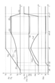
- the component of the regenerative braking force Fg is “the portion sandwiched between the X axis and the curve EFGH of the regenerative braking force Fg”
- the component of the rear wheel friction braking force Fmr is “the two-dot chain line (D) and the curve EFGH.
- the components of the front wheel friction braking force Fmf correspond to “the portion sandwiched between the required braking force Fd and the two-dot chain line (D)”, respectively.
- the front wheel torque Tqf and the rear wheel Torque Tqr is determined to be “0 (zero)”.
- the actual front wheel ratio Hfa is “0”
- the rear wheel ratio Hra is “1”.
- the second embodiment has the following effects.
- the required braking force Fd can be achieved only by the regenerative braking force Fg
- the front wheel and rear wheel torques Tqf and Tqr are set to “0”, and no friction braking force is generated, so that the energy regeneration by the generator GN is maximized. Can be done.
- the required braking force Fd cannot be achieved only by the regenerative braking force Fg
- the front wheel torque Tqf is maintained at “0” while the front wheel torque Tqf is maintained at the front wheel reference force Ft (the distribution ratio hf of the braking force is taken into consideration). It is increased to a value corresponding to the front wheel braking force). For this reason, the desired front-rear ratio hf can be achieved quickly.
- the rear wheel torque Tqr is increased, the increase gradient of the front wheel torque Tqf is decreased, and the increase in the front wheel torque Tqf is continued. For this reason, the desired distribution ratio hf can be suitably maintained.
- the regenerative braking force Fg increases, and the increase in the regenerative braking force Fg corresponds to the rear wheel friction braking force Fmr (rear wheel torque Tqr).
- Alone cannot be compensated for, it can be adjusted by reducing the front wheel friction braking force Fmf (front wheel torque Tqf).
- the regenerative braking force Fg may be adjusted to be smaller than the maximum regenerative force Fx so as to achieve the required braking force Fd.
- the braking control device SC is provided in a vehicle having a regenerative generator GN on the front wheels WHf.
- the braking control device SC is provided with an actuator YU that applies the front wheel torque Tqf and the rear wheel torque Tqr, and a controller ECU that controls the actuator YU and adjusts the front wheel torque Tqf and the rear wheel torque Tqr.
- the front wheel friction braking force Fmf is generated by the front wheel torque Tqf.
- the rear wheel friction braking force Fmr is generated by the rear wheel torque Tqr.
- the front wheel torque Tqf and the rear wheel torque Tqr is determined to be “0 (zero)”.
- the rear wheel torque Tqr is increased from “0” before the front wheel torque Tqf is increased from “0”.
- the regenerative braking force Fg reaches the maximum regenerative force Fx
- the required braking force Fd corresponding to the braking operation amount Ba of the vehicle and the front-rear ratio Hr (or the front-rear ratio Hf of the braking force acting on the vehicle).
- the complementary braking force Fh is calculated based on the required braking force Fd and the maximum regenerative force Fx.
- the complementary braking force Fh is equal to or less than the rear wheel reference force Fs (that is, when “Fh ⁇ Fs”)
- the front wheel torque Tqf is maintained at “0” and the rear wheel torque Tqr is supplemented. Increased based on power Fh.
- the complementary braking force Fh is larger than the rear wheel reference force Fs (that is, when “Fh> Fs”)
- the front wheel torque Tqf is based on the complementary braking force Fh and the rear wheel reference force Fs.
- the rear wheel torque Tqr is increased based on the rear wheel reference force Fs.
- the front wheel torque Tqf and the rear wheel torque Tqr are set to “0”, so that the maximum energy can be regenerated.
- the increase in the rear wheel torque Tqr is started before the front wheel torque Tqf is started to increase. Can be reached at.
- the front wheel torque Tqf is increased based on the complementary braking force Fh and the rear wheel reference force Fs, and the rear wheel torque Tqr is increased to the rear wheel reference force Fs. Therefore, the distribution ratio Hf can be reliably maintained.
- the braking control device SC is provided in a vehicle having a regenerative generator GN on the rear wheel WHr.
- the regenerative braking force Fg when the regenerative braking force Fg does not reach the maximum regenerative force Fx, the front wheel torque Tqf and the rear wheel torque Tqr are determined to be “0 (zero)”.
- the front wheel torque Tqf is increased from “0” before the rear wheel torque Tqr is increased from “0”.
- the required braking force Fd corresponding to the braking operation amount Ba and the front-rear ratio Hf (or front-rear ratio Hr) of the braking force acting on the vehicle are set. Based on this, the front wheel reference force Ft is calculated.
- the complementary braking force Fh is calculated based on the required braking force Fd and the maximum regenerative force Fx.
- the front wheel torque Tqf is increased based on the front wheel reference force Ft.
- the rear wheel torque Tqr is increased based on the complementary braking force Fh and the front wheel reference force Ft.
- the front wheel torque Tqf and the rear wheel torque Tqr are set to “0”, so that the amount of energy regeneration can be maximized.
- the increase in the front wheel torque Tqf is started before the increase in the rear wheel torque Tqr is started. Can be achieved.
- the front wheel torque Tqf is increased based on the front wheel reference force Ft, and the rear wheel torque Tqr is based on the complementary braking force Fh and the front wheel reference force Ft. Therefore, the distribution ratio Hf can be reliably maintained.
- the rear wheel reference force Fs is calculated based on the rear wheel ratio Hr
- the linear pressure regulating valves UB and UC are adjusted such that the valve opening amount is adjusted according to the energization amount.
- the pressure regulating valves UB and UC are on / off valves, the opening and closing of the valves may be controlled by a duty ratio, and the hydraulic pressure may be linearly controlled.
- the configuration of the disc type braking device (disc brake) is exemplified.
- the friction member is a brake pad
- the rotating member is a brake disk.
- a drum type braking device drum brake
- a brake drum is employed instead of the caliper.
- the friction member is a brake shoe
- the rotating member is a brake drum.
- the hydraulic braking control device SC in which the braking torques Tqf and Tqr are adjusted by the braking fluid BF is exemplified.
- an electric brake control device SC that does not use the brake fluid BF is employed.
- the rotation of the electric motor is converted into linear power by a screw mechanism or the like, and the friction member is pressed against the rotation member KT.
- the braking torques Tqf and Tqr are generated by the pressing force of the friction member against the rotating member KT generated using the electric motor as a power source instead of the braking fluid pressure Pw.
- a configuration in which a hydraulic type and an electric type are combined may be used.
- the first and second adjustment hydraulic pressure sensors PB and PC are provided in the pressure adjustment fluid path HC so as to detect the first and second adjustment hydraulic pressures Pb and Pc.
- a master hydraulic pressure sensor PQ may be used instead of the first and second adjustment hydraulic pressure sensors PB and PC.
- the second adjustment hydraulic pressure sensor PC is omitted, and the actual second adjustment hydraulic pressure Pc can be calculated based on the detection value Pm of the master hydraulic pressure sensor PQ.
Landscapes
- Engineering & Computer Science (AREA)
- Mechanical Engineering (AREA)
- Transportation (AREA)
- Power Engineering (AREA)
- Chemical & Material Sciences (AREA)
- Electromagnetism (AREA)
- Physics & Mathematics (AREA)
- Combustion & Propulsion (AREA)
- General Engineering & Computer Science (AREA)
- Automation & Control Theory (AREA)
- Regulating Braking Force (AREA)
- Electric Propulsion And Braking For Vehicles (AREA)
- Hydraulic Control Valves For Brake Systems (AREA)
Priority Applications (3)
| Application Number | Priority Date | Filing Date | Title |
|---|---|---|---|
| DE112019000740.8T DE112019000740T5 (de) | 2018-02-09 | 2019-02-05 | Bremssteuerungsvorrichtung für ein Fahrzeug |
| US16/967,432 US11718181B2 (en) | 2018-02-09 | 2019-02-05 | Braking control device for vehicle |
| CN201980012026.9A CN111683843B (zh) | 2018-02-09 | 2019-02-05 | 车辆的制动控制装置 |
Applications Claiming Priority (2)
| Application Number | Priority Date | Filing Date | Title |
|---|---|---|---|
| JP2018021735A JP7146165B2 (ja) | 2018-02-09 | 2018-02-09 | 車両の制動制御装置 |
| JP2018-021735 | 2018-02-09 |
Publications (1)
| Publication Number | Publication Date |
|---|---|
| WO2019156035A1 true WO2019156035A1 (ja) | 2019-08-15 |
Family
ID=67547982
Family Applications (1)
| Application Number | Title | Priority Date | Filing Date |
|---|---|---|---|
| PCT/JP2019/003932 Ceased WO2019156035A1 (ja) | 2018-02-09 | 2019-02-05 | 車両の制動制御装置 |
Country Status (5)
| Country | Link |
|---|---|
| US (1) | US11718181B2 (enExample) |
| JP (1) | JP7146165B2 (enExample) |
| CN (1) | CN111683843B (enExample) |
| DE (1) | DE112019000740T5 (enExample) |
| WO (1) | WO2019156035A1 (enExample) |
Cited By (1)
| Publication number | Priority date | Publication date | Assignee | Title |
|---|---|---|---|---|
| WO2022202763A1 (ja) * | 2021-03-22 | 2022-09-29 | 株式会社アドヴィックス | 車両の制動制御装置 |
Families Citing this family (7)
| Publication number | Priority date | Publication date | Assignee | Title |
|---|---|---|---|---|
| JP6935710B2 (ja) * | 2017-09-26 | 2021-09-15 | 株式会社アドヴィックス | 車両の制動制御装置 |
| JP7146167B2 (ja) | 2018-06-26 | 2022-10-04 | 株式会社アドヴィックス | 車両の制動制御装置 |
| DE102019210269A1 (de) * | 2019-07-11 | 2021-01-14 | Robert Bosch Gmbh | Detektionsverfahren und Sensorvorrichtung für einen elektromechanischen Bremskraftverstärker eines fahrzeugeigenen hydraulischen Bremssystems |
| EP4212379A4 (en) * | 2020-09-08 | 2024-03-20 | Hitachi Astemo, Ltd. | VEHICLE CONTROL DEVICE, VEHICLE CONTROL METHOD, AND VEHICLE CONTROL SYSTEM |
| JP7392680B2 (ja) * | 2021-04-06 | 2023-12-06 | トヨタ自動車株式会社 | 車両用制動システム |
| DE102022205840A1 (de) * | 2022-06-08 | 2023-12-14 | Robert Bosch Gesellschaft mit beschränkter Haftung | Steuervorrichtung und Verfahren zum Betreiben eines rekuperativen Bremssystems eines Fahrzeugs |
| KR20240006759A (ko) * | 2022-07-06 | 2024-01-16 | 현대자동차주식회사 | 전동화 차량 및 이의 제어 방법 |
Citations (3)
| Publication number | Priority date | Publication date | Assignee | Title |
|---|---|---|---|---|
| JP2007276579A (ja) * | 2006-04-05 | 2007-10-25 | Nissan Motor Co Ltd | 車両の制動制御装置 |
| WO2013008298A1 (ja) * | 2011-07-11 | 2013-01-17 | トヨタ自動車株式会社 | ブレーキシステム、アクチュエータ制御装置 |
| JP2018019537A (ja) * | 2016-07-29 | 2018-02-01 | いすゞ自動車株式会社 | 車両及び車両の制御方法 |
Family Cites Families (41)
| Publication number | Priority date | Publication date | Assignee | Title |
|---|---|---|---|---|
| US4962969A (en) * | 1988-09-30 | 1990-10-16 | Ford Motor Company | Adaptive controller for regenerative and friction braking system |
| JP3189981B2 (ja) * | 1991-12-05 | 2001-07-16 | 本田技研工業株式会社 | 電動車両の制動装置 |
| US5253929A (en) * | 1991-12-20 | 1993-10-19 | Toyota Jidosha Kabushiki Kaisha | Brake control system of electric vehicle |
| JP3158583B2 (ja) * | 1991-12-24 | 2001-04-23 | トヨタ自動車株式会社 | 電気自動車の制動制御装置 |
| US5378053A (en) * | 1993-12-07 | 1995-01-03 | Alliedsignal Inc. | Maximized regenerative braking vehicle braking controller |
| JP3546277B2 (ja) * | 1996-01-29 | 2004-07-21 | トヨタ自動車株式会社 | 電気自動車の制動装置 |
| JP3541621B2 (ja) * | 1997-06-10 | 2004-07-14 | トヨタ自動車株式会社 | 車両用制動装置 |
| JP2001169405A (ja) * | 1999-12-09 | 2001-06-22 | Toyota Motor Corp | 車輌用制動装置 |
| JP2001247025A (ja) * | 2000-03-03 | 2001-09-11 | Toyota Motor Corp | 車両制動システムおよび複系統制動システム |
| JP4147976B2 (ja) * | 2002-09-13 | 2008-09-10 | 日産自動車株式会社 | 複合ブレーキの協調制御装置 |
| JP4333205B2 (ja) * | 2003-04-24 | 2009-09-16 | 日産自動車株式会社 | 複合ブレーキの協調制御装置 |
| JP4400453B2 (ja) * | 2004-01-15 | 2010-01-20 | 日産自動車株式会社 | 車両の制動制御装置 |
| US9630508B2 (en) * | 2004-03-09 | 2017-04-25 | Ford Global Technologies, Llc | System and method for controlling regenerative braking in a vehicle |
| US8152245B2 (en) * | 2004-09-09 | 2012-04-10 | Kelsey-Hayes Company | Vehicle system having regenerative brake control |
| US7311163B2 (en) * | 2004-11-16 | 2007-12-25 | Eaton Corporation | Regeneration and brake management system |
| EP1824698B1 (de) * | 2004-12-09 | 2014-03-05 | Continental Teves AG & Co. oHG | Verfahren zur steuerung eines bremssystems eines kraftfahrzeuges |
| JP2006168460A (ja) * | 2004-12-14 | 2006-06-29 | Advics:Kk | 車両用ブレーキ制御装置 |
| JP4742778B2 (ja) * | 2004-12-22 | 2011-08-10 | 株式会社アドヴィックス | 車両用ブレーキ制御装置 |
| JP2007030631A (ja) * | 2005-07-25 | 2007-02-08 | Advics:Kk | 車両用ブレーキ制御装置 |
| US7322659B2 (en) * | 2005-08-04 | 2008-01-29 | Gm Global Technology Operations, Inc. | Method and system for brake distribution in a regenerative braking system |
| JP2008222121A (ja) * | 2007-03-14 | 2008-09-25 | Toyota Motor Corp | 車輌の制動装置 |
| JP4441544B2 (ja) * | 2007-03-15 | 2010-03-31 | 本田技研工業株式会社 | 車両の回生協調制動装置 |
| US10272902B2 (en) * | 2009-09-02 | 2019-04-30 | Toyota Jidosha Kabushiki Kaisha | Brake control device |
| KR101404087B1 (ko) * | 2010-05-12 | 2014-06-05 | 주식회사 만도 | 회생 제동 제어 방법 |
| JP5514661B2 (ja) * | 2010-07-23 | 2014-06-04 | 株式会社日立製作所 | 電動車両の駆動制御装置 |
| JP5386042B2 (ja) * | 2010-09-09 | 2014-01-15 | ボッシュ株式会社 | 車両用ブレーキ装置及び車両用ブレーキ装置の制御方法 |
| JP5699044B2 (ja) * | 2011-06-29 | 2015-04-08 | 日立オートモティブシステムズ株式会社 | ブレーキ制御装置 |
| US9352655B2 (en) * | 2012-01-30 | 2016-05-31 | Bosch Corporation | Brake device for vehicle and control method thereof |
| JP2013180598A (ja) * | 2012-02-29 | 2013-09-12 | Nissan Motor Co Ltd | 電動車両の変速制御装置 |
| JP5908779B2 (ja) | 2012-05-01 | 2016-04-26 | 日立オートモティブシステムズ株式会社 | ブレーキ制御装置、ブレーキ制御方法 |
| DE102013200471A1 (de) * | 2013-01-15 | 2014-07-17 | Robert Bosch Gmbh | Aggregat für ein hydraulisches Bremssystem, hydraulisches Bremssystem, Steuervorrichtung zum Zusammenwirken mit einem hydraulischen Bremssystem und Verfahren zum Betreiben eines hydraulischen Bremssystems |
| DE102013200604A1 (de) * | 2013-01-16 | 2014-07-17 | Robert Bosch Gmbh | Verfahren und Vorrichtung zum Betreiben eines Bremssystems |
| JP2014230457A (ja) * | 2013-05-27 | 2014-12-08 | 日産自動車株式会社 | 車両用制動制御装置 |
| CN105683009B (zh) * | 2013-11-08 | 2018-01-26 | 本田技研工业株式会社 | 制动力控制系统 |
| KR101628148B1 (ko) * | 2014-08-27 | 2016-06-08 | 현대자동차 주식회사 | 하이브리드 차량의 회생 제동 장치 및 방법 |
| JP6623960B2 (ja) * | 2016-02-26 | 2019-12-25 | 株式会社アドヴィックス | 車両用制動装置 |
| JP6737733B2 (ja) * | 2017-04-05 | 2020-08-12 | 株式会社アドヴィックス | 車両の制動制御装置 |
| IT201700038501A1 (it) * | 2017-04-07 | 2018-10-07 | Freni Brembo Spa | Metodo e sistema per il controllo della coppia frenante rigenerativa di un veicolo |
| DE102017111077A1 (de) * | 2017-05-22 | 2018-11-22 | Lsp Innovative Automotive Systems Gmbh | Bremsvorrichtung, insbesondere für elektrisch angetriebene Kraftfahrzeuge |
| JP6847492B2 (ja) * | 2017-06-02 | 2021-03-24 | 日立Astemo株式会社 | 電動車両の制御装置、電動車両の制御システム及び電動車両の制御方法 |
| DE102017223064A1 (de) * | 2017-12-18 | 2019-06-19 | Audi Ag | Verfahren zur Steuerung eines Bremssystems zur Einstellung einer Gesamtbremsmomentaufteilung zwischen einer ersten und einer zweiten Achse eines Kraftfahrzeugs sowie ein Bremssystem zur Durchführung des Verfahrens |
-
2018
- 2018-02-09 JP JP2018021735A patent/JP7146165B2/ja active Active
-
2019
- 2019-02-05 CN CN201980012026.9A patent/CN111683843B/zh active Active
- 2019-02-05 US US16/967,432 patent/US11718181B2/en active Active
- 2019-02-05 WO PCT/JP2019/003932 patent/WO2019156035A1/ja not_active Ceased
- 2019-02-05 DE DE112019000740.8T patent/DE112019000740T5/de active Pending
Patent Citations (3)
| Publication number | Priority date | Publication date | Assignee | Title |
|---|---|---|---|---|
| JP2007276579A (ja) * | 2006-04-05 | 2007-10-25 | Nissan Motor Co Ltd | 車両の制動制御装置 |
| WO2013008298A1 (ja) * | 2011-07-11 | 2013-01-17 | トヨタ自動車株式会社 | ブレーキシステム、アクチュエータ制御装置 |
| JP2018019537A (ja) * | 2016-07-29 | 2018-02-01 | いすゞ自動車株式会社 | 車両及び車両の制御方法 |
Cited By (3)
| Publication number | Priority date | Publication date | Assignee | Title |
|---|---|---|---|---|
| WO2022202763A1 (ja) * | 2021-03-22 | 2022-09-29 | 株式会社アドヴィックス | 車両の制動制御装置 |
| JP2022145999A (ja) * | 2021-03-22 | 2022-10-05 | 株式会社アドヴィックス | 車両の制動制御装置 |
| JP7505427B2 (ja) | 2021-03-22 | 2024-06-25 | 株式会社アドヴィックス | 車両の制動制御装置 |
Also Published As
| Publication number | Publication date |
|---|---|
| CN111683843B (zh) | 2022-06-21 |
| DE112019000740T5 (de) | 2020-10-22 |
| US20210213835A1 (en) | 2021-07-15 |
| JP2019137203A (ja) | 2019-08-22 |
| CN111683843A (zh) | 2020-09-18 |
| US11718181B2 (en) | 2023-08-08 |
| JP7146165B2 (ja) | 2022-10-04 |
Similar Documents
| Publication | Publication Date | Title |
|---|---|---|
| JP7146165B2 (ja) | 車両の制動制御装置 | |
| JP7067099B2 (ja) | 車両の制動制御装置 | |
| JP6935712B2 (ja) | 車両の制動制御装置 | |
| JP7040316B2 (ja) | 車両の制動制御装置 | |
| CN112313124B (zh) | 车辆制动控制装置 | |
| JP6935710B2 (ja) | 車両の制動制御装置 | |
| WO2020045565A1 (ja) | 車両の制動制御装置 | |
| WO2020004240A1 (ja) | 車両の制動制御装置 | |
| JP7172526B2 (ja) | 車両の制動制御装置 | |
| US20220314812A1 (en) | Braking control device for vehicle | |
| JP2023034694A (ja) | 車両の制動制御装置 | |
| JP7070001B2 (ja) | 車両の制動制御装置 | |
| JP6935711B2 (ja) | 車両の制動制御装置 | |
| JP7091797B2 (ja) | 車両の制動制御装置 | |
| JP2025073196A (ja) | 車両の制動制御装置 |
Legal Events
| Date | Code | Title | Description |
|---|---|---|---|
| 121 | Ep: the epo has been informed by wipo that ep was designated in this application |
Ref document number: 19750497 Country of ref document: EP Kind code of ref document: A1 |
|
| 122 | Ep: pct application non-entry in european phase |
Ref document number: 19750497 Country of ref document: EP Kind code of ref document: A1 |