WO2019151099A1 - 減速装置 - Google Patents
減速装置 Download PDFInfo
- Publication number
- WO2019151099A1 WO2019151099A1 PCT/JP2019/002204 JP2019002204W WO2019151099A1 WO 2019151099 A1 WO2019151099 A1 WO 2019151099A1 JP 2019002204 W JP2019002204 W JP 2019002204W WO 2019151099 A1 WO2019151099 A1 WO 2019151099A1
- Authority
- WO
- WIPO (PCT)
- Prior art keywords
- ball
- cage
- balls
- plate portion
- rotation
- Prior art date
- Legal status (The legal status is an assumption and is not a legal conclusion. Google has not performed a legal analysis and makes no representation as to the accuracy of the status listed.)
- Ceased
Links
Images




Classifications
-
- F—MECHANICAL ENGINEERING; LIGHTING; HEATING; WEAPONS; BLASTING
- F16—ENGINEERING ELEMENTS AND UNITS; GENERAL MEASURES FOR PRODUCING AND MAINTAINING EFFECTIVE FUNCTIONING OF MACHINES OR INSTALLATIONS; THERMAL INSULATION IN GENERAL
- F16H—GEARING
- F16H1/00—Toothed gearings for conveying rotary motion
- F16H1/28—Toothed gearings for conveying rotary motion with gears having orbital motion
- F16H1/32—Toothed gearings for conveying rotary motion with gears having orbital motion in which the central axis of the gearing lies inside the periphery of an orbital gear
-
- F—MECHANICAL ENGINEERING; LIGHTING; HEATING; WEAPONS; BLASTING
- F16—ENGINEERING ELEMENTS AND UNITS; GENERAL MEASURES FOR PRODUCING AND MAINTAINING EFFECTIVE FUNCTIONING OF MACHINES OR INSTALLATIONS; THERMAL INSULATION IN GENERAL
- F16H—GEARING
- F16H25/00—Gearings comprising primarily only cams, cam-followers and screw-and-nut mechanisms
- F16H25/04—Gearings comprising primarily only cams, cam-followers and screw-and-nut mechanisms for conveying rotary motion
- F16H25/06—Gearings comprising primarily only cams, cam-followers and screw-and-nut mechanisms for conveying rotary motion with intermediate members guided along tracks on both rotary members
Definitions
- the present invention relates to a reduction gear.
- reduction gears that are interposed between a disc and a second disc and have a cage for holding a ball (for example, Patent Documents 1 and 2).
- This type of speed reducer is excellent in that it is small and provides a large reduction ratio.
- the speed reducer proposed in Patent Document 1 has a winding first groove that intersects a first reference circle of a plane with a constant pitch and a winding first groove that intersects a second reference circle of the plane with a constant pitch.
- the first and second discs each having two grooves, and the first and second discs are respectively held by the first and second cages.
- the first retainer is fixed and the second retainer is rotatably supported by two rolling elements facing each other. Since this speed reducer is a differential type, it is described that a large speed reduction ratio can be obtained and a small speed reducer is possible.
- the speed reducer proposed in Patent Document 2 includes a drive cam having a circular cam groove engaged with a ball and decentered from the rotation axis by a certain distance, a driven cam having a petal-shaped cam groove engaged with the ball, A cage having a groove for holding the ball movably in the radial direction, with the cage sandwiched between the drive cam and the follower cam on opposite sides of the surface having the respective cam grooves. These are coupled so as to be rotatable around the same axis, and the rotation of the drive cam is decelerated and transmitted to the driven cam via the movement of the ball. It is described that this reduction gear is small and is manufactured at a low cost by relatively simple processing and can obtain a reduction gear ratio of about 6.
- the main parts of this type of reducer are composed of a ball, an input plate, an output plate, and a cage.
- This type of reducer is a mechanism that converts the eccentric rotational motion of the input plate into a reciprocating linear motion of the ball, converts it back into a rotational motion again by the wavy groove of the output plate, and transmits the driving force by decelerating it. Since the rolling bearing is rotatably provided in the eccentric part on the side, it is possible to absorb the rotational difference between the input plate and the output plate and transmit torque while the ball rolls.
- the rotation speed of the ball rotation is determined by the rotation speed of the input plate and the rotation speed of the output plate.
- the cage that holds the ball is a component that does not contribute to the power transmission of the speed reducer, and reducing the frictional force between the ball and the pocket of the cage is important for improving the efficiency.
- the frictional force generated by the contact between the ball and the pocket of the cage acts only in the radial direction around the input shaft or the rotation shaft of the output plate. Therefore, it can be seen that the frictional force generated between the ball and the cage does not contribute to power transmission.
- the present invention can achieve a small and high reduction ratio, and can suppress fluctuations in rotational speed and vibration on the output side, and can improve efficiency due to slip generated in the balls and the pockets of the cage.
- An object of the present invention is to provide a speed reducer that has improved deterioration and deterioration of durability.
- the present inventors firstly create a new ball engagement groove capable of obtaining a synchronous rotational property in a decelerating rotational motion between the input side and the output side.
- the present invention has been achieved by the idea that the durability can be improved, the transmission efficiency can be improved, and the vibration can be reduced by reducing the coefficient of friction between the ball and the pocket of the cage.
- the present invention includes an input-side rotating member having an input plate portion in which a first ball engaging groove is formed, and coaxially with the rotation axis of the input-side rotating member.
- An output-side rotating member that is disposed and has an output plate portion in which a second ball engaging groove is formed, and a plurality of members that engage with both the ball engaging grooves of the input plate portion and the output plate portion facing in the axial direction.
- a cage having a plurality of pockets for holding the ball so as to be movable in the radial direction. The cage is provided so as not to rotate with respect to the rotating shaft, and is engaged with both the ball engaging grooves.
- the track center line of the second ball engaging groove is formed as a wavy curve
- the wavy curve indicates that the ball is engaged with the first ball engagement groove when the output side rotation member is at a rotation angle ( ⁇ / i) at an arbitrary rotation angle ( ⁇ ) of the input side rotation member.
- the center of the ball engaged with the first ball engaging groove is positioned on the track center line of the second ball engaging groove. Therefore, the 1st ball engagement groove and the 2nd ball engagement groove can be set up certainly.
- the ball is held while rolling by contact between the ball and the ball engagement groove. It is possible to suppress heat generation with the pocket of the vessel.
- an eccentric portion is formed on the rotation shaft of the input side rotating member, and an input plate portion is rotatably mounted on the eccentric portion via a rolling bearing.
- the track center line of the first ball engaging groove is circular, the center of curvature is eccentric with respect to the axis of the rotation shaft of the input side rotation member, and the axis of the rotation shaft and the second ball It is preferable that the distance (R) between the engagement groove and the track center line satisfies the following formula.
- R distance between the axis of the rotating shaft and the orbit center line of the second ball engaging groove
- a eccentricity
- i reduction ratio
- ⁇ rotation angle of the output side rotating member
- r orbit of the first ball engaging groove
- the present invention it is possible to realize a reduction gear that is small and has a high reduction ratio, and that can suppress fluctuations in rotational speed and vibration on the output side.
- a reduction gear that is small and has a high reduction ratio, and that can suppress fluctuations in rotational speed and vibration on the output side.
- FIG. 3 is a schematic diagram of FIG. 2.
- FIG. 2 is a side view of the input plate section taken along line EE in FIG. 1. It is sectional drawing of the input board part in the GG line of FIG. 4A.
- FIG. 2 is a side view of the output plate portion taken along the line FF in FIG. 1. It is sectional drawing of the output board part in the HH line
- FIG. 1 is a longitudinal sectional view showing the entire reduction gear device according to the present embodiment.
- the speed reducer 1 mainly includes an input side rotating member 2, an output side rotating member 3, a ball 4, and a cage 5, and is incorporated in cases 6a and 6b.
- the input-side rotating member 2 includes a rotating shaft 7, an eccentric cam 8, a rolling bearing 9, and an input plate portion 10.
- An eccentric cam 8 is fitted on the outer diameter surface of the rotating shaft 7.
- the center O1 of the cylindrical outer diameter surface 8a of the eccentric cam 8 is eccentric in the radial direction by an eccentric amount a with respect to the axis X1 of the rotating shaft 7.
- a rolling bearing 9 is mounted between the cylindrical outer diameter surface 8 a of the eccentric cam 8 and the cylindrical inner diameter surface 10 a of the input plate portion 10, and the input plate portion 10 is rotatably supported by the eccentric cam 8.
- the center O1 of the cylindrical outer diameter surface 8a of the eccentric cam 8 is also the center of the input plate portion 10.
- the input plate portion 10 performs a revolving motion with a swaying radius a around the axis X1 of the rotating shaft 7.
- the rotating shaft 7 is rotatably supported by a rolling bearing 11 attached to the inner diameter surface 21 of the case 6a and a rolling bearing 12 attached to the inner diameter surface 5a of the cage 5.
- FIG. 4A and FIG. 4B a first ball engaging groove 13 is formed on the side surface 10b of the input plate portion 10.
- 4A is a side view of the input plate 10 taken along the line EE in FIG. 1
- FIG. 4B is a cross-sectional view of the input plate 10 taken along the line GG in FIG. 4A. 4A and 4B, the chamfering of the outer diameter surface of the input plate portion 10 and the illustration of the inner diameter surface 10a (see FIG. 1) on which the rolling bearing 9 is mounted are omitted.
- the track center line L1 of the first ball engaging groove 13 is formed in a circular shape with a radius r, and the first ball engaging groove 13 is formed of a part of the torus surface.
- the center of curvature of the track center line L ⁇ b> 1 is located at the cylindrical outer diameter surface 8 a of the eccentric cam 8 and the center O ⁇ b> 1 of the input plate portion 10.
- the center O1 is eccentric with respect to the axis X1 of the rotating shaft 7 by the amount of eccentricity a.
- the center Ob of the ball 4 is positioned on the track center line L1 of the first ball engaging groove 13.
- the track center line of the first ball engaging groove is the track of the center Ob of the ball 4 when the ball 4 is moved along the first ball engaging groove 13. Means.
- the output-side rotating member 3 includes an output plate portion 3a and a shaft portion 3b, and the output plate portion 3a and the shaft portion 3b are integrally formed.
- the shaft portion 3b serves as an output shaft.
- the output side rotating member 3 is rotatably supported by a rolling bearing 14 mounted on the inner diameter surface 20 of the case 6b and a rolling bearing 15 mounted on the stepped outer diameter surface 5b of the cage 5.
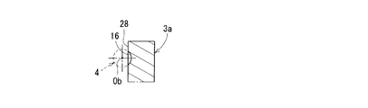
- the second ball engaging groove 16 is formed on the side surface 28 of the output plate portion 3a.
- 5A is a side view of the output plate portion 3a taken along line FF in FIG. 1
- FIG. 5B is a cross-sectional view of the output plate portion 3a along line HH in FIG. 5A.
- 5A and 5B the chamfering of the outer diameter surface of the output plate portion 3a and the illustration of the inner diameter surface 22 (see FIG. 1) on which the rolling bearing 15 is mounted are omitted.
- the orbit center line L2 of the second ball engaging groove 16 is formed in a wavy curve, and the axis X2, the orbit center line L2 and the distance R of the shaft portion 3b vary with respect to the reference pitch circle radius PCR.
- the wavy curve of the trajectory center line L2 is formed with 10 peaks having a distance R larger than the reference pitch circle radius PCR and 10 valleys having a distance R smaller than the reference pitch circle radius PCR.
- the shaft center X2 of the shaft portion 3b is arranged coaxially with the shaft center X1 of the rotating shaft 7.
- the center Ob of the ball 4 is positioned on the track center line L2 of the second ball engaging groove 16.
- the wavy curve of the orbit center line of the second ball engaging groove means a curve that alternately intersects the reference pitch circle of the radius PCR at a constant pitch.
- the track center line of the second ball engaging groove means the locus of the center Ob of the ball 4 when the ball 4 is moved along the second ball engaging groove 16. Details of the wavy curve of the track center line L2 of the second ball engaging groove 16 will be described later.
- the cage 5 is disposed between the side surfaces 10b and 28 of the input plate portion 10 and the output plate portion 3a that face each other in the axial direction.
- the cage 5 is provided with a pocket 17 for holding the ball 4.
- a through hole 18 is provided on the outer peripheral side of the cage 5, and a pin 19 is fitted into the through hole 18.
- the cage 5 is attached to the cases 6 a and 6 b so as not to rotate. As a result, the cage 5 cannot rotate with respect to the rotation shaft 7 of the input side rotation member 2.
- the fixing bolts 24 are fitted into the through holes 25 of the case 6b and the through holes 23 of the cage 5, and are screwed into the screw holes 26 of the case 6a to fasten the cases 6a, 6b and the cage 5. .
- the pocket 17 of the cage 5 is formed by a long hole extending radially in the radial direction around the axis X1 of the rotating shaft 7.
- 6A is a side view of the cage taken along the line II in FIG. 1
- FIG. 6B is an enlarged view of a portion J in FIG. 6A.
- illustration of the inner diameter surface 5 a on which the through holes 18 and 23 on the outer peripheral side of the cage 5 and the rolling bearing 12 in FIG. 1 are mounted is omitted.
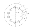
- the number of pockets 17 of the cage 5 is 11, which is one more than the number of ridges or valleys (10) of the wavy curve of the track center line L2, and the pockets 17 are formed at equal intervals in the circumferential direction.
- One ball 4 is arranged in each pocket 17. Since each pocket 17 is formed of a long hole extending radially in the radial direction, the balls 4 in each pocket 17 are within a predetermined amount m in the radial outer side and the radial inner side with respect to the reference pitch circle radius PCR. Can move.
- the cage 5 is provided so as not to rotate, and the ball 4 is held by a pocket 17 of the cage 5 so as to be movable in the radial direction.
- the cage 5 or the pocket 17 is made of a material having a lower friction coefficient than the ball engaging grooves 13 and 16 (usually using steel) of the input side rotating member 2 and the output side rotating member 3. It is possible to suppress heat generation with the pocket 17 while rolling the ball 4 due to contact between the ball 4 and the ball engaging grooves 13 and 16.
- FIG. 7 shows the analysis result of the transmission efficiency of the speed reducer using general-purpose mechanism analysis software (ADAMS).
- ADAMS general-purpose mechanism analysis software
- the transmission efficiency is improved by about 9% on average by changing the friction coefficient from 0.1 to 0.05.
- FIG. 8 shows the amount of influence on the transmission efficiency with respect to the coefficient of friction between the ball and the cage calculated in the same manner as in FIG. There is almost no change when the friction coefficient between the ball 4 and the cage 5 is 0.3 or more or 0.01 or less.
- Transmission efficiency is effective when the friction coefficient between the ball 4 and the cage 5 or the pocket 17 is reduced to a lower value when the friction coefficient between steel and steel (with grease) is 0.01 to 0.3. There is.
- ⁇ Select a material with a low coefficient of friction, such as resin or copper alloy, for the material of the cage 5.
- the friction coefficient can be lowered by changing the cage 5 or the pocket 17 to the following material. It is known that the dynamic friction coefficient in a dry state (solid vs. solid) is about 0.4 to 0.6 in the case of steel vs. steel.
- the following friction coefficient values indicate the dynamic friction coefficients of steel vs “each material” in the dry state. In addition to the material of the contact surface, the friction coefficient changes depending on the presence or absence of lubricants such as oil and the surface roughness. In this case, the friction coefficient in the dry state where the conditions are relatively consistent is compared. It was decided to do.
- Copper alloys including brass, bronze, and lead bronze 0.15 to 0.3
- Resin materials with excellent lubricity PTFE, nylon, polyacetal, UHPE, PEEK, etc.
- Ceramics 0.2 to 0.5
- Other materials with a small friction coefficient may be applied.
- the friction coefficient can be lowered by applying the following surface treatment to the cage 5 or the pocket 17.
- Surface treatment includes DLC (diamond-like carbon): 0.05 to 0.1, resin coating such as fluorine: 0.08 to 0.12, electroless nickel plating including fluorine resin composite: 0.08 to 0. 12. Hard chrome plating: 0.1 to 0.16, or any other treatment that reduces the friction coefficient.
- the surface treatment may be at least one of the contact surfaces of the balls 4 or the balls 4 of the cage 5.
- dimples may be processed on the contact surface of the ball 4 or the ball 4 of the cage 5 to form an oil sump on the contact surface, thereby reducing the influence of sliding.
- the reduction ratio i is obtained by the following equation, and the reduction ratio i is ⁇ 1/10.
- Reduction ratio i (number of ridges ⁇ number of balls) / number of ridges
- the minus sign of the reduction ratio i indicates that the rotation direction of the output side rotation member 3 is opposite to the rotation direction of the input side rotation member 2. It means that.
- FIG. 2 is a perspective view showing a main part of FIG. 1
- FIG. 3 is a schematic view showing a state in which the ball of FIG. 2 is arranged in the pocket of the cage. 3, the outer diameter chamfer of the input plate portion 10 in FIG. 2, the inner diameter surface 10a for mounting the bearing, the outer diameter side through holes 18 and 23 of the cage 5, the inner diameter surface 5a for mounting the bearing, and the bearing mounting of the output plate portion 3a. Illustration of the inner diameter surface 22 and the shaft portion 3b is omitted.
- the axis X1 of the rotating shaft 7 of the input side rotating member 2 and the axis X2 of the output side member 3 are arranged coaxially, and the axis of the cage 5 is also arranged coaxially with the axes X1 and X2.
- the center O1 (see FIG. 4A) of the track center line L1 of the first ball engaging groove 13 of the input plate portion 10 is eccentric with respect to the axis X1 of the rotating shaft 7 by an eccentric amount a.
- the ball 4 is shown in a state of being engaged with the second ball engaging groove 16 of the output plate portion 3 b, but this ball 4 is disposed in the pocket 17 of the cage 5 and is shown in the drawing from the pocket 17.
- the ball 4 protrudes toward the front side, and the ball 4 engages with the first ball engaging groove 13 (see FIG. 1) of the input plate portion 10. That is, as shown in FIG. 3, the front side of the ball 4 in the pocket 17 of the cage 5 is engaged with the first ball engagement groove 13 (see FIG. 1) of the input plate portion 10, and the drawing of the ball 4 is made.
- the back side engages with the second ball engaging groove 16 of the output plate portion 3b.
- FIG. 9 is a view showing the second ball engaging groove and the ball arrangement state of the output plate portion
- FIG. 10 is an enlarged view of the K portion of FIG. 9 to show the movement of the ball with respect to the second ball engaging groove
- FIG. 11 is a schematic diagram for deriving a reference curve of the second ball engaging groove of the output plate portion.
- the cage 5 is provided so as not to rotate, and the ball 4 is held by the pocket 17 of the cage 5 so as to be movable in the radial direction.
- the ball 4 engages with the second ball engagement groove 16 of the output plate portion 3a at an equiangular position in the circumferential direction.
- ⁇ 360 °, where ⁇ is an angle formed by a straight line connecting the axis X2 and the centers Ob 0 and Ob ′ of the balls 4 adjacent in the circumferential direction. / 11, and the angle ⁇ between all adjacent balls 4 is equal.
- a state in which the output side rotating member 3 is decelerated relative to the input side rotating member 2 and rotates synchronously will be described with reference to FIG.
- the cage 5 is configured to be non-rotatable with respect to the rotation of the input side rotating member 2 and the output side rotating member 3. Therefore, the pocket 17 indicated by the solid line in FIG. 10 does not move in the circumferential direction.
- a horizontal center line in FIG. 10 indicates a position where the rotation angle ⁇ of the rotation shaft 7 of the input side rotation member 2 is 0 °.
- the ball 4 is located in the outermost radial direction in the pocket 17.
- Rotary shaft 7 is rotated a rotation angle .theta.1, since the position of the whirling radius a of the input plate 10 is moved to the position of the rotation angle theta 1, to engage the first ball engagement groove 13 of the input plate 10
- the ball 4 moves in the pocket 17 toward the inner diameter side in the radial direction, and the center of the ball 4 is at the position Ob 1 .
- the center Ob 1 of the ball 4 is a second ball engaging Since it is positioned on the track center line L2 of the groove 16, the output plate portion 3a rotates by the rotation angle i ⁇ 1 shown in FIG.
- the speed reduction device 1 of the present embodiment is characterized in that the rotational motion decelerated from the input side rotating member 2 to the output side rotating member 3 is transmitted in a synchronous rotation. Thereby, high rotation accuracy and vibration suppression can be achieved. Since the rotational motion decelerated from the input-side rotating member 2 to the output-side rotating member 3 is transmitted by synchronous rotation, the shape of the wavy curve of the track center line L2 of the second ball engaging groove 16 of the output plate portion 3a. Is set.
- FIG. 11 is a schematic diagram for deriving a wavy curve of the track center line L2 of the second ball engaging groove 16.
- the horizontal center line in FIG. 11 corresponds to the horizontal center line in FIG. 10 and indicates a position where the rotation angle ⁇ of the rotation shaft 7 of the input side rotation member 2 is 0 °.
- the track center line L1 ⁇ of the engagement groove 13 is indicated by a solid line.
- the orbital center line L1 of the first ball engaging groove 13 of the input plate portion 10 is circular with a radius r with respect to the axis X1 of the rotation shaft 7 of the input side rotating member 2, and the center O1 has an eccentric amount a. Only eccentric. For this reason, when the rotation angle ⁇ is 0 °, the center of the track center line L1 is at O1 0 , and the center of the ball 4 is Ob 0 and is located on the outermost side in the radial direction. The ball 4 is restrained on the line n by the pocket 17 of the cage 5 and can move in the radial direction.
- the distance R between the axis X1 of the rotating shaft 7 and the track center line L2 of the second ball engaging groove is expressed as follows.
- R distance between the axis of the rotating shaft and the orbit center line of the second ball engaging groove
- a eccentricity
- i reduction ratio
- ⁇ rotation angle of the output side rotating member
- r orbit of the first ball engaging groove Centerline radius
- the operation of the reduction gear 1 of the present embodiment will be summarized and described.
- the input plate portion 10 revolves around the axis X1 of the rotating shaft 7.
- the input member 10 since the input plate portion 10 is rotatable with respect to the eccentric cam 8 provided on the rotation shaft 7, the input member 10 hardly rotates. Thereby, the relative friction amount between the pocket of the cage or the ball engaging groove and the ball can be reduced, and the transmission efficiency from the input side rotating member to the output side rotating member can be improved.
- each ball 4 that engages with the first ball engaging groove 13 formed of the circular track center line L1 is restrained in the pocket 17 of the cage 5 that is provided so as not to rotate. And move in the radial direction respectively.
- the operation of the reduction gear 1 of the present embodiment is as described above, and it is possible to realize a reduction gear that is small and has a high reduction ratio and that can suppress fluctuations in rotational speed and vibration on the output side.
- the first ball engaging groove formed of a circular track center line and the second ball engaging groove formed of a wavy curved track center line can simplify the shape of the ball engaging groove as a whole, and are easy to manufacture. And cost reduction.
- the circular track center line L1 of the first ball engagement groove 13 provided in the input plate portion 10 is exemplified as a circular shape, but the present invention is not limited to this and corresponds to the speed reduction ratio i. It may be a polygonal orbit centerline.
- the track center line of the first ball engagement groove and the track center line of the second ball engagement groove for synchronously rotating the input side rotation member and the output side rotation member can be appropriately set.
- the input plate portion 10 is configured to be rotatable with respect to the eccentric cam 8 provided on the rotation shaft 7, but the input plate portion and the rotation shaft are integrated. It may be. Further, in the speed reduction device 1 of the present embodiment, the configuration in which the separate eccentric cam 8 is fitted to the rotating shaft 7 is illustrated, but the present invention is not limited to this, and the rotating shaft and the eccentric cam are configured integrally. Good.
- the speed reduction ratio i is -1/10.
- the speed reduction ratio i is about 1/5 to 1/20, and can be set as necessary.
- the number of peaks / valleys of the wavy curve of the track center line of the ball engagement groove, the number of pockets of the cage, and the number of balls may be appropriately set according to the reduction ratio i.
- the present invention is not limited to the embodiment described above, and the pocket of the cage may be formed of a member different from the cage, and the cage may be composed of a plurality of members.
- the present invention can of course be implemented in various forms without departing from the scope of the present invention, and the scope of the present invention is shown by the claims and further described in the claims. Including the equivalent meaning of and all changes within the scope.
Landscapes
- Engineering & Computer Science (AREA)
- General Engineering & Computer Science (AREA)
- Mechanical Engineering (AREA)
- Transmission Devices (AREA)
- Retarders (AREA)
Applications Claiming Priority (2)
| Application Number | Priority Date | Filing Date | Title |
|---|---|---|---|
| JP2018-017122 | 2018-02-02 | ||
| JP2018017122A JP6996994B2 (ja) | 2018-02-02 | 2018-02-02 | 減速装置 |
Publications (1)
| Publication Number | Publication Date |
|---|---|
| WO2019151099A1 true WO2019151099A1 (ja) | 2019-08-08 |
Family
ID=67479937
Family Applications (1)
| Application Number | Title | Priority Date | Filing Date |
|---|---|---|---|
| PCT/JP2019/002204 Ceased WO2019151099A1 (ja) | 2018-02-02 | 2019-01-24 | 減速装置 |
Country Status (2)
| Country | Link |
|---|---|
| JP (1) | JP6996994B2 (https=) |
| WO (1) | WO2019151099A1 (https=) |
Cited By (1)
| Publication number | Priority date | Publication date | Assignee | Title |
|---|---|---|---|---|
| US20250314289A1 (en) * | 2024-04-05 | 2025-10-09 | Sorin Vasile Cora | Logarithmic hollow shaft speed reducer |
Citations (5)
| Publication number | Priority date | Publication date | Assignee | Title |
|---|---|---|---|---|
| JPH0510400A (ja) * | 1991-07-02 | 1993-01-19 | Kamo Seiko Kk | 減速機 |
| JPH053713U (ja) * | 1991-06-28 | 1993-01-22 | 株式会社椿本チエイン | ボール式減速機 |
| JP2003172419A (ja) * | 2001-12-10 | 2003-06-20 | Nsk Ltd | ボール式変速装置 |
| JP2009024765A (ja) * | 2007-07-19 | 2009-02-05 | Nsk Ltd | ボール式減速機 |
| JP2016191447A (ja) * | 2015-03-31 | 2016-11-10 | Ntn株式会社 | サイクロイド減速機およびこれを備えたモータ駆動装置 |
-
2018
- 2018-02-02 JP JP2018017122A patent/JP6996994B2/ja not_active Expired - Fee Related
-
2019
- 2019-01-24 WO PCT/JP2019/002204 patent/WO2019151099A1/ja not_active Ceased
Patent Citations (5)
| Publication number | Priority date | Publication date | Assignee | Title |
|---|---|---|---|---|
| JPH053713U (ja) * | 1991-06-28 | 1993-01-22 | 株式会社椿本チエイン | ボール式減速機 |
| JPH0510400A (ja) * | 1991-07-02 | 1993-01-19 | Kamo Seiko Kk | 減速機 |
| JP2003172419A (ja) * | 2001-12-10 | 2003-06-20 | Nsk Ltd | ボール式変速装置 |
| JP2009024765A (ja) * | 2007-07-19 | 2009-02-05 | Nsk Ltd | ボール式減速機 |
| JP2016191447A (ja) * | 2015-03-31 | 2016-11-10 | Ntn株式会社 | サイクロイド減速機およびこれを備えたモータ駆動装置 |
Cited By (2)
| Publication number | Priority date | Publication date | Assignee | Title |
|---|---|---|---|---|
| US20250314289A1 (en) * | 2024-04-05 | 2025-10-09 | Sorin Vasile Cora | Logarithmic hollow shaft speed reducer |
| US12601391B2 (en) * | 2024-04-05 | 2026-04-14 | Sorin Vasile Cora | Logarithmic hollow shaft speed reducer |
Also Published As
| Publication number | Publication date |
|---|---|
| JP6996994B2 (ja) | 2022-01-17 |
| JP2019132401A (ja) | 2019-08-08 |
Similar Documents
| Publication | Publication Date | Title |
|---|---|---|
| JP5596575B2 (ja) | 電動式直動アクチュエータおよび電動式ディスクブレーキ装置 | |
| CN109477560B (zh) | 减速装置 | |
| JP2018021602A (ja) | 減速装置 | |
| CN102648359A (zh) | 等速联轴器 | |
| JP2018132188A (ja) | 転動要素軸受トランスミッション | |
| EP4299949A1 (en) | Internally meshing planetary gear apparatus and joint apparatus for robot | |
| US20230398682A1 (en) | Internally Engaged Planetary Gear Device and Robot Joint Device | |
| WO2020240743A1 (ja) | ボールねじ機構及び直線移動装置 | |
| WO2019151099A1 (ja) | 減速装置 | |
| JP2008196582A (ja) | 遊星回転体用円錐ころ軸受 | |
| CN113007313B (zh) | 一种高效啮合蜗轮 | |
| JPWO2018159539A1 (ja) | ローラギヤカム機構 | |
| JP6077870B2 (ja) | ハイブリッド変速機 | |
| JP2019044874A (ja) | 減速装置 | |
| JP4656867B2 (ja) | 軸継手 | |
| CN113015864A (zh) | 波动齿轮装置的波动发生器 | |
| JP2016200218A (ja) | 遊星ローラ式の動力伝達装置 | |
| JP2017501360A (ja) | トランスミッション及びその部品 | |
| JP7229479B2 (ja) | ロケットエンジンのバルブアクチュエータ | |
| JP6816304B2 (ja) | ユニット構造の波動歯車装置 | |
| JP2014206286A (ja) | 電動式ディスクブレーキ装置 | |
| JP6981739B2 (ja) | 減速装置 | |
| WO2012086327A1 (ja) | 歯車伝動装置 | |
| JP6812163B2 (ja) | 減速装置 | |
| JP2008232314A (ja) | 遊星回転体用円錐ころ軸受 |
Legal Events
| Date | Code | Title | Description |
|---|---|---|---|
| 121 | Ep: the epo has been informed by wipo that ep was designated in this application |
Ref document number: 19748429 Country of ref document: EP Kind code of ref document: A1 |
|
| NENP | Non-entry into the national phase |
Ref country code: DE |
|
| 122 | Ep: pct application non-entry in european phase |
Ref document number: 19748429 Country of ref document: EP Kind code of ref document: A1 |