WO2019151099A1 - Speed reduction device - Google Patents
Speed reduction device Download PDFInfo
- Publication number
- WO2019151099A1 WO2019151099A1 PCT/JP2019/002204 JP2019002204W WO2019151099A1 WO 2019151099 A1 WO2019151099 A1 WO 2019151099A1 JP 2019002204 W JP2019002204 W JP 2019002204W WO 2019151099 A1 WO2019151099 A1 WO 2019151099A1
- Authority
- WO
- WIPO (PCT)
- Prior art keywords
- ball
- cage
- balls
- plate portion
- rotation
- Prior art date
Links
Images


Classifications
-
- F—MECHANICAL ENGINEERING; LIGHTING; HEATING; WEAPONS; BLASTING
- F16—ENGINEERING ELEMENTS AND UNITS; GENERAL MEASURES FOR PRODUCING AND MAINTAINING EFFECTIVE FUNCTIONING OF MACHINES OR INSTALLATIONS; THERMAL INSULATION IN GENERAL
- F16H—GEARING
- F16H1/00—Toothed gearings for conveying rotary motion
- F16H1/28—Toothed gearings for conveying rotary motion with gears having orbital motion
- F16H1/32—Toothed gearings for conveying rotary motion with gears having orbital motion in which the central axis of the gearing lies inside the periphery of an orbital gear
-
- F—MECHANICAL ENGINEERING; LIGHTING; HEATING; WEAPONS; BLASTING
- F16—ENGINEERING ELEMENTS AND UNITS; GENERAL MEASURES FOR PRODUCING AND MAINTAINING EFFECTIVE FUNCTIONING OF MACHINES OR INSTALLATIONS; THERMAL INSULATION IN GENERAL
- F16H—GEARING
- F16H25/00—Gearings comprising primarily only cams, cam-followers and screw-and-nut mechanisms
- F16H25/04—Gearings comprising primarily only cams, cam-followers and screw-and-nut mechanisms for conveying rotary motion
- F16H25/06—Gearings comprising primarily only cams, cam-followers and screw-and-nut mechanisms for conveying rotary motion with intermediate members guided along tracks on both rotary members
Definitions
- the present invention relates to a reduction gear.
- reduction gears that are interposed between a disc and a second disc and have a cage for holding a ball (for example, Patent Documents 1 and 2).
- This type of speed reducer is excellent in that it is small and provides a large reduction ratio.
- the speed reducer proposed in Patent Document 1 has a winding first groove that intersects a first reference circle of a plane with a constant pitch and a winding first groove that intersects a second reference circle of the plane with a constant pitch.
- the first and second discs each having two grooves, and the first and second discs are respectively held by the first and second cages.
- the first retainer is fixed and the second retainer is rotatably supported by two rolling elements facing each other. Since this speed reducer is a differential type, it is described that a large speed reduction ratio can be obtained and a small speed reducer is possible.
- the speed reducer proposed in Patent Document 2 includes a drive cam having a circular cam groove engaged with a ball and decentered from the rotation axis by a certain distance, a driven cam having a petal-shaped cam groove engaged with the ball, A cage having a groove for holding the ball movably in the radial direction, with the cage sandwiched between the drive cam and the follower cam on opposite sides of the surface having the respective cam grooves. These are coupled so as to be rotatable around the same axis, and the rotation of the drive cam is decelerated and transmitted to the driven cam via the movement of the ball. It is described that this reduction gear is small and is manufactured at a low cost by relatively simple processing and can obtain a reduction gear ratio of about 6.
- the main parts of this type of reducer are composed of a ball, an input plate, an output plate, and a cage.
- This type of reducer is a mechanism that converts the eccentric rotational motion of the input plate into a reciprocating linear motion of the ball, converts it back into a rotational motion again by the wavy groove of the output plate, and transmits the driving force by decelerating it. Since the rolling bearing is rotatably provided in the eccentric part on the side, it is possible to absorb the rotational difference between the input plate and the output plate and transmit torque while the ball rolls.
- the rotation speed of the ball rotation is determined by the rotation speed of the input plate and the rotation speed of the output plate.
- the cage that holds the ball is a component that does not contribute to the power transmission of the speed reducer, and reducing the frictional force between the ball and the pocket of the cage is important for improving the efficiency.
- the frictional force generated by the contact between the ball and the pocket of the cage acts only in the radial direction around the input shaft or the rotation shaft of the output plate. Therefore, it can be seen that the frictional force generated between the ball and the cage does not contribute to power transmission.
- the present invention can achieve a small and high reduction ratio, and can suppress fluctuations in rotational speed and vibration on the output side, and can improve efficiency due to slip generated in the balls and the pockets of the cage.
- An object of the present invention is to provide a speed reducer that has improved deterioration and deterioration of durability.
- the present inventors firstly create a new ball engagement groove capable of obtaining a synchronous rotational property in a decelerating rotational motion between the input side and the output side.
- the present invention has been achieved by the idea that the durability can be improved, the transmission efficiency can be improved, and the vibration can be reduced by reducing the coefficient of friction between the ball and the pocket of the cage.
- the present invention includes an input-side rotating member having an input plate portion in which a first ball engaging groove is formed, and coaxially with the rotation axis of the input-side rotating member.
- An output-side rotating member that is disposed and has an output plate portion in which a second ball engaging groove is formed, and a plurality of members that engage with both the ball engaging grooves of the input plate portion and the output plate portion facing in the axial direction.
- a cage having a plurality of pockets for holding the ball so as to be movable in the radial direction. The cage is provided so as not to rotate with respect to the rotating shaft, and is engaged with both the ball engaging grooves.
- the track center line of the second ball engaging groove is formed as a wavy curve
- the wavy curve indicates that the ball is engaged with the first ball engagement groove when the output side rotation member is at a rotation angle ( ⁇ / i) at an arbitrary rotation angle ( ⁇ ) of the input side rotation member.
- the center of the ball engaged with the first ball engaging groove is positioned on the track center line of the second ball engaging groove. Therefore, the 1st ball engagement groove and the 2nd ball engagement groove can be set up certainly.
- the ball is held while rolling by contact between the ball and the ball engagement groove. It is possible to suppress heat generation with the pocket of the vessel.
- an eccentric portion is formed on the rotation shaft of the input side rotating member, and an input plate portion is rotatably mounted on the eccentric portion via a rolling bearing.
- the track center line of the first ball engaging groove is circular, the center of curvature is eccentric with respect to the axis of the rotation shaft of the input side rotation member, and the axis of the rotation shaft and the second ball It is preferable that the distance (R) between the engagement groove and the track center line satisfies the following formula.
- R distance between the axis of the rotating shaft and the orbit center line of the second ball engaging groove
- a eccentricity
- i reduction ratio
- ⁇ rotation angle of the output side rotating member
- r orbit of the first ball engaging groove
- the present invention it is possible to realize a reduction gear that is small and has a high reduction ratio, and that can suppress fluctuations in rotational speed and vibration on the output side.
- a reduction gear that is small and has a high reduction ratio, and that can suppress fluctuations in rotational speed and vibration on the output side.
- FIG. 3 is a schematic diagram of FIG. 2.
- FIG. 2 is a side view of the input plate section taken along line EE in FIG. 1. It is sectional drawing of the input board part in the GG line of FIG. 4A.
- FIG. 2 is a side view of the output plate portion taken along the line FF in FIG. 1. It is sectional drawing of the output board part in the HH line
- FIG. 1 is a longitudinal sectional view showing the entire reduction gear device according to the present embodiment.
- the speed reducer 1 mainly includes an input side rotating member 2, an output side rotating member 3, a ball 4, and a cage 5, and is incorporated in cases 6a and 6b.
- the input-side rotating member 2 includes a rotating shaft 7, an eccentric cam 8, a rolling bearing 9, and an input plate portion 10.
- An eccentric cam 8 is fitted on the outer diameter surface of the rotating shaft 7.
- the center O1 of the cylindrical outer diameter surface 8a of the eccentric cam 8 is eccentric in the radial direction by an eccentric amount a with respect to the axis X1 of the rotating shaft 7.
- a rolling bearing 9 is mounted between the cylindrical outer diameter surface 8 a of the eccentric cam 8 and the cylindrical inner diameter surface 10 a of the input plate portion 10, and the input plate portion 10 is rotatably supported by the eccentric cam 8.
- the center O1 of the cylindrical outer diameter surface 8a of the eccentric cam 8 is also the center of the input plate portion 10.
- the input plate portion 10 performs a revolving motion with a swaying radius a around the axis X1 of the rotating shaft 7.
- the rotating shaft 7 is rotatably supported by a rolling bearing 11 attached to the inner diameter surface 21 of the case 6a and a rolling bearing 12 attached to the inner diameter surface 5a of the cage 5.
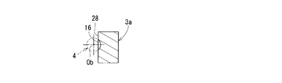
- FIG. 4A and FIG. 4B a first ball engaging groove 13 is formed on the side surface 10b of the input plate portion 10.
- 4A is a side view of the input plate 10 taken along the line EE in FIG. 1
- FIG. 4B is a cross-sectional view of the input plate 10 taken along the line GG in FIG. 4A. 4A and 4B, the chamfering of the outer diameter surface of the input plate portion 10 and the illustration of the inner diameter surface 10a (see FIG. 1) on which the rolling bearing 9 is mounted are omitted.
- the track center line L1 of the first ball engaging groove 13 is formed in a circular shape with a radius r, and the first ball engaging groove 13 is formed of a part of the torus surface.
- the center of curvature of the track center line L ⁇ b> 1 is located at the cylindrical outer diameter surface 8 a of the eccentric cam 8 and the center O ⁇ b> 1 of the input plate portion 10.
- the center O1 is eccentric with respect to the axis X1 of the rotating shaft 7 by the amount of eccentricity a.
- the center Ob of the ball 4 is positioned on the track center line L1 of the first ball engaging groove 13.
- the track center line of the first ball engaging groove is the track of the center Ob of the ball 4 when the ball 4 is moved along the first ball engaging groove 13. Means.
- the output-side rotating member 3 includes an output plate portion 3a and a shaft portion 3b, and the output plate portion 3a and the shaft portion 3b are integrally formed.
- the shaft portion 3b serves as an output shaft.
- the output side rotating member 3 is rotatably supported by a rolling bearing 14 mounted on the inner diameter surface 20 of the case 6b and a rolling bearing 15 mounted on the stepped outer diameter surface 5b of the cage 5.
- the second ball engaging groove 16 is formed on the side surface 28 of the output plate portion 3a.
- 5A is a side view of the output plate portion 3a taken along line FF in FIG. 1
- FIG. 5B is a cross-sectional view of the output plate portion 3a along line HH in FIG. 5A.
- 5A and 5B the chamfering of the outer diameter surface of the output plate portion 3a and the illustration of the inner diameter surface 22 (see FIG. 1) on which the rolling bearing 15 is mounted are omitted.
- the orbit center line L2 of the second ball engaging groove 16 is formed in a wavy curve, and the axis X2, the orbit center line L2 and the distance R of the shaft portion 3b vary with respect to the reference pitch circle radius PCR.
- the wavy curve of the trajectory center line L2 is formed with 10 peaks having a distance R larger than the reference pitch circle radius PCR and 10 valleys having a distance R smaller than the reference pitch circle radius PCR.
- the shaft center X2 of the shaft portion 3b is arranged coaxially with the shaft center X1 of the rotating shaft 7.
- the center Ob of the ball 4 is positioned on the track center line L2 of the second ball engaging groove 16.
- the wavy curve of the orbit center line of the second ball engaging groove means a curve that alternately intersects the reference pitch circle of the radius PCR at a constant pitch.
- the track center line of the second ball engaging groove means the locus of the center Ob of the ball 4 when the ball 4 is moved along the second ball engaging groove 16. Details of the wavy curve of the track center line L2 of the second ball engaging groove 16 will be described later.
- the cage 5 is disposed between the side surfaces 10b and 28 of the input plate portion 10 and the output plate portion 3a that face each other in the axial direction.
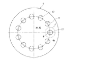
- the cage 5 is provided with a pocket 17 for holding the ball 4.
- a through hole 18 is provided on the outer peripheral side of the cage 5, and a pin 19 is fitted into the through hole 18.
- the cage 5 is attached to the cases 6 a and 6 b so as not to rotate. As a result, the cage 5 cannot rotate with respect to the rotation shaft 7 of the input side rotation member 2.
- the fixing bolts 24 are fitted into the through holes 25 of the case 6b and the through holes 23 of the cage 5, and are screwed into the screw holes 26 of the case 6a to fasten the cases 6a, 6b and the cage 5. .
- the pocket 17 of the cage 5 is formed by a long hole extending radially in the radial direction around the axis X1 of the rotating shaft 7.
- 6A is a side view of the cage taken along the line II in FIG. 1
- FIG. 6B is an enlarged view of a portion J in FIG. 6A.
- illustration of the inner diameter surface 5 a on which the through holes 18 and 23 on the outer peripheral side of the cage 5 and the rolling bearing 12 in FIG. 1 are mounted is omitted.
- the number of pockets 17 of the cage 5 is 11, which is one more than the number of ridges or valleys (10) of the wavy curve of the track center line L2, and the pockets 17 are formed at equal intervals in the circumferential direction.
- One ball 4 is arranged in each pocket 17. Since each pocket 17 is formed of a long hole extending radially in the radial direction, the balls 4 in each pocket 17 are within a predetermined amount m in the radial outer side and the radial inner side with respect to the reference pitch circle radius PCR. Can move.
- the cage 5 is provided so as not to rotate, and the ball 4 is held by a pocket 17 of the cage 5 so as to be movable in the radial direction.
- the cage 5 or the pocket 17 is made of a material having a lower friction coefficient than the ball engaging grooves 13 and 16 (usually using steel) of the input side rotating member 2 and the output side rotating member 3. It is possible to suppress heat generation with the pocket 17 while rolling the ball 4 due to contact between the ball 4 and the ball engaging grooves 13 and 16.
- FIG. 7 shows the analysis result of the transmission efficiency of the speed reducer using general-purpose mechanism analysis software (ADAMS).
- ADAMS general-purpose mechanism analysis software
- the transmission efficiency is improved by about 9% on average by changing the friction coefficient from 0.1 to 0.05.
- FIG. 8 shows the amount of influence on the transmission efficiency with respect to the coefficient of friction between the ball and the cage calculated in the same manner as in FIG. There is almost no change when the friction coefficient between the ball 4 and the cage 5 is 0.3 or more or 0.01 or less.
- Transmission efficiency is effective when the friction coefficient between the ball 4 and the cage 5 or the pocket 17 is reduced to a lower value when the friction coefficient between steel and steel (with grease) is 0.01 to 0.3. There is.
- ⁇ Select a material with a low coefficient of friction, such as resin or copper alloy, for the material of the cage 5.
- the friction coefficient can be lowered by changing the cage 5 or the pocket 17 to the following material. It is known that the dynamic friction coefficient in a dry state (solid vs. solid) is about 0.4 to 0.6 in the case of steel vs. steel.
- the following friction coefficient values indicate the dynamic friction coefficients of steel vs “each material” in the dry state. In addition to the material of the contact surface, the friction coefficient changes depending on the presence or absence of lubricants such as oil and the surface roughness. In this case, the friction coefficient in the dry state where the conditions are relatively consistent is compared. It was decided to do.
- Copper alloys including brass, bronze, and lead bronze 0.15 to 0.3
- Resin materials with excellent lubricity PTFE, nylon, polyacetal, UHPE, PEEK, etc.
- Ceramics 0.2 to 0.5
- Other materials with a small friction coefficient may be applied.
- the friction coefficient can be lowered by applying the following surface treatment to the cage 5 or the pocket 17.
- Surface treatment includes DLC (diamond-like carbon): 0.05 to 0.1, resin coating such as fluorine: 0.08 to 0.12, electroless nickel plating including fluorine resin composite: 0.08 to 0. 12. Hard chrome plating: 0.1 to 0.16, or any other treatment that reduces the friction coefficient.
- the surface treatment may be at least one of the contact surfaces of the balls 4 or the balls 4 of the cage 5.
- dimples may be processed on the contact surface of the ball 4 or the ball 4 of the cage 5 to form an oil sump on the contact surface, thereby reducing the influence of sliding.
- the reduction ratio i is obtained by the following equation, and the reduction ratio i is ⁇ 1/10.
- Reduction ratio i (number of ridges ⁇ number of balls) / number of ridges
- the minus sign of the reduction ratio i indicates that the rotation direction of the output side rotation member 3 is opposite to the rotation direction of the input side rotation member 2. It means that.
- FIG. 2 is a perspective view showing a main part of FIG. 1
- FIG. 3 is a schematic view showing a state in which the ball of FIG. 2 is arranged in the pocket of the cage. 3, the outer diameter chamfer of the input plate portion 10 in FIG. 2, the inner diameter surface 10a for mounting the bearing, the outer diameter side through holes 18 and 23 of the cage 5, the inner diameter surface 5a for mounting the bearing, and the bearing mounting of the output plate portion 3a. Illustration of the inner diameter surface 22 and the shaft portion 3b is omitted.
- the axis X1 of the rotating shaft 7 of the input side rotating member 2 and the axis X2 of the output side member 3 are arranged coaxially, and the axis of the cage 5 is also arranged coaxially with the axes X1 and X2.
- the center O1 (see FIG. 4A) of the track center line L1 of the first ball engaging groove 13 of the input plate portion 10 is eccentric with respect to the axis X1 of the rotating shaft 7 by an eccentric amount a.
- the ball 4 is shown in a state of being engaged with the second ball engaging groove 16 of the output plate portion 3 b, but this ball 4 is disposed in the pocket 17 of the cage 5 and is shown in the drawing from the pocket 17.
- the ball 4 protrudes toward the front side, and the ball 4 engages with the first ball engaging groove 13 (see FIG. 1) of the input plate portion 10. That is, as shown in FIG. 3, the front side of the ball 4 in the pocket 17 of the cage 5 is engaged with the first ball engagement groove 13 (see FIG. 1) of the input plate portion 10, and the drawing of the ball 4 is made.
- the back side engages with the second ball engaging groove 16 of the output plate portion 3b.
- FIG. 9 is a view showing the second ball engaging groove and the ball arrangement state of the output plate portion
- FIG. 10 is an enlarged view of the K portion of FIG. 9 to show the movement of the ball with respect to the second ball engaging groove
- FIG. 11 is a schematic diagram for deriving a reference curve of the second ball engaging groove of the output plate portion.
- the cage 5 is provided so as not to rotate, and the ball 4 is held by the pocket 17 of the cage 5 so as to be movable in the radial direction.
- the ball 4 engages with the second ball engagement groove 16 of the output plate portion 3a at an equiangular position in the circumferential direction.
- ⁇ 360 °, where ⁇ is an angle formed by a straight line connecting the axis X2 and the centers Ob 0 and Ob ′ of the balls 4 adjacent in the circumferential direction. / 11, and the angle ⁇ between all adjacent balls 4 is equal.
- a state in which the output side rotating member 3 is decelerated relative to the input side rotating member 2 and rotates synchronously will be described with reference to FIG.
- the cage 5 is configured to be non-rotatable with respect to the rotation of the input side rotating member 2 and the output side rotating member 3. Therefore, the pocket 17 indicated by the solid line in FIG. 10 does not move in the circumferential direction.
- a horizontal center line in FIG. 10 indicates a position where the rotation angle ⁇ of the rotation shaft 7 of the input side rotation member 2 is 0 °.
- the ball 4 is located in the outermost radial direction in the pocket 17.
- Rotary shaft 7 is rotated a rotation angle .theta.1, since the position of the whirling radius a of the input plate 10 is moved to the position of the rotation angle theta 1, to engage the first ball engagement groove 13 of the input plate 10
- the ball 4 moves in the pocket 17 toward the inner diameter side in the radial direction, and the center of the ball 4 is at the position Ob 1 .
- the center Ob 1 of the ball 4 is a second ball engaging Since it is positioned on the track center line L2 of the groove 16, the output plate portion 3a rotates by the rotation angle i ⁇ 1 shown in FIG.
- the speed reduction device 1 of the present embodiment is characterized in that the rotational motion decelerated from the input side rotating member 2 to the output side rotating member 3 is transmitted in a synchronous rotation. Thereby, high rotation accuracy and vibration suppression can be achieved. Since the rotational motion decelerated from the input-side rotating member 2 to the output-side rotating member 3 is transmitted by synchronous rotation, the shape of the wavy curve of the track center line L2 of the second ball engaging groove 16 of the output plate portion 3a. Is set.
- FIG. 11 is a schematic diagram for deriving a wavy curve of the track center line L2 of the second ball engaging groove 16.
- the horizontal center line in FIG. 11 corresponds to the horizontal center line in FIG. 10 and indicates a position where the rotation angle ⁇ of the rotation shaft 7 of the input side rotation member 2 is 0 °.
- the track center line L1 ⁇ of the engagement groove 13 is indicated by a solid line.
- the orbital center line L1 of the first ball engaging groove 13 of the input plate portion 10 is circular with a radius r with respect to the axis X1 of the rotation shaft 7 of the input side rotating member 2, and the center O1 has an eccentric amount a. Only eccentric. For this reason, when the rotation angle ⁇ is 0 °, the center of the track center line L1 is at O1 0 , and the center of the ball 4 is Ob 0 and is located on the outermost side in the radial direction. The ball 4 is restrained on the line n by the pocket 17 of the cage 5 and can move in the radial direction.
- the distance R between the axis X1 of the rotating shaft 7 and the track center line L2 of the second ball engaging groove is expressed as follows.
- R distance between the axis of the rotating shaft and the orbit center line of the second ball engaging groove
- a eccentricity
- i reduction ratio
- ⁇ rotation angle of the output side rotating member
- r orbit of the first ball engaging groove Centerline radius
- the operation of the reduction gear 1 of the present embodiment will be summarized and described.
- the input plate portion 10 revolves around the axis X1 of the rotating shaft 7.
- the input member 10 since the input plate portion 10 is rotatable with respect to the eccentric cam 8 provided on the rotation shaft 7, the input member 10 hardly rotates. Thereby, the relative friction amount between the pocket of the cage or the ball engaging groove and the ball can be reduced, and the transmission efficiency from the input side rotating member to the output side rotating member can be improved.
- each ball 4 that engages with the first ball engaging groove 13 formed of the circular track center line L1 is restrained in the pocket 17 of the cage 5 that is provided so as not to rotate. And move in the radial direction respectively.
- the operation of the reduction gear 1 of the present embodiment is as described above, and it is possible to realize a reduction gear that is small and has a high reduction ratio and that can suppress fluctuations in rotational speed and vibration on the output side.
- the first ball engaging groove formed of a circular track center line and the second ball engaging groove formed of a wavy curved track center line can simplify the shape of the ball engaging groove as a whole, and are easy to manufacture. And cost reduction.
- the circular track center line L1 of the first ball engagement groove 13 provided in the input plate portion 10 is exemplified as a circular shape, but the present invention is not limited to this and corresponds to the speed reduction ratio i. It may be a polygonal orbit centerline.
- the track center line of the first ball engagement groove and the track center line of the second ball engagement groove for synchronously rotating the input side rotation member and the output side rotation member can be appropriately set.
- the input plate portion 10 is configured to be rotatable with respect to the eccentric cam 8 provided on the rotation shaft 7, but the input plate portion and the rotation shaft are integrated. It may be. Further, in the speed reduction device 1 of the present embodiment, the configuration in which the separate eccentric cam 8 is fitted to the rotating shaft 7 is illustrated, but the present invention is not limited to this, and the rotating shaft and the eccentric cam are configured integrally. Good.
- the speed reduction ratio i is -1/10.
- the speed reduction ratio i is about 1/5 to 1/20, and can be set as necessary.
- the number of peaks / valleys of the wavy curve of the track center line of the ball engagement groove, the number of pockets of the cage, and the number of balls may be appropriately set according to the reduction ratio i.
- the present invention is not limited to the embodiment described above, and the pocket of the cage may be formed of a member different from the cage, and the cage may be composed of a plurality of members.
- the present invention can of course be implemented in various forms without departing from the scope of the present invention, and the scope of the present invention is shown by the claims and further described in the claims. Including the equivalent meaning of and all changes within the scope.
Landscapes
- Engineering & Computer Science (AREA)
- General Engineering & Computer Science (AREA)
- Mechanical Engineering (AREA)
- Transmission Devices (AREA)
- Retarders (AREA)
Abstract
The purpose of the present invention is to provide a speed reduction device which has a small size and with which a high speed reduction ratio can be obtained, and high rotational accuracy and the suppression of vibration can be achieved. This speed reduction device 1 is characterized by comprising: an input-side rotary member 2 having a first ball engagement recess 13 formed therein; an output-side rotary member 3 coaxially arranged with a rotary shaft 7 of the input-side rotary member 2 and having a second ball engagement recess 16 formed therein; a plurality of balls 4 that engage with the two ball engagement recesses 13, 16 facing each other in the axial direction; and a retainer 5 having a plurality of pockets 17 that hold the balls 4 so that the balls 4 can move in a radial direction, wherein the retainer 5 is provided so as not to be rotatable with respect to the rotary shaft 7, the rotation of the input-side rotary member 20 is reduced in speed and transmitted to the output-side rotary member 3 through the balls 4 engaging with the two ball engagement recesses 13, 16, and a surface treatment or a material which has a smaller friction coefficient with the balls than that of the contact between the balls and the ball engagement recesses is used on at least the surface of the member that constitutes the pockets of the retainer.
Description
本発明は減速装置に関する。
The present invention relates to a reduction gear.
ボール係合溝を備えた入力側の第1の円板と、ボール係合溝を備えた出力側の第2の円板と、ボール係合溝に係合する複数のボールと、第1の円板と第2の円板との間に介在し、ボールを保持する保持器を備えた減速機は既に提案されている(例えば、特許文献1、2)。この形式の減速機は、小型で大きな減速比が得られるなどの点で優れている。
A first disk on the input side provided with a ball engaging groove, a second disk on the output side provided with a ball engaging groove, a plurality of balls engaged with the ball engaging groove, and a first There have already been proposed reduction gears that are interposed between a disc and a second disc and have a cage for holding a ball (for example, Patent Documents 1 and 2). This type of speed reducer is excellent in that it is small and provides a large reduction ratio.
特許文献1に提案された減速機は、平面の第1の基準円を一定のピッチで交錯する曲がりくねった第1の溝と前記平面の第2の基準円を一定のピッチで交錯する曲がりくねった第2の溝をそれぞれ備えた第1、第2の円板と、前記第1の円板と前記第2の円板は、第1、第2の保持器により、それぞれ保持された第1、第2の転動体を介して対向し、前記第1の保持器は固定され、前記第2の保持器は回転自在に支持されている。この減速機は、差動式であるため、大きな減速比を得ることができ、かつ小型の減速機が可能であると記載されている。
The speed reducer proposed in Patent Document 1 has a winding first groove that intersects a first reference circle of a plane with a constant pitch and a winding first groove that intersects a second reference circle of the plane with a constant pitch. The first and second discs each having two grooves, and the first and second discs are respectively held by the first and second cages. The first retainer is fixed and the second retainer is rotatably supported by two rolling elements facing each other. Since this speed reducer is a differential type, it is described that a large speed reduction ratio can be obtained and a small speed reducer is possible.
特許文献2に提案された減速機は、ボールと係合し回転軸から一定距離偏心した円形のカム溝を有する駆動カムと、ボールと係合する花びら状のカム溝を備えた従動カムと、ボールを半径方向に移動可能に保持する溝部を有する保持器とを具備し、保持器を間に挟んで、その両側に駆動カムと従動カムとをそれぞれのカム溝を備えた面を対向させて、同一軸線周りに回転可能に連結し、ボールの動作を介して駆動カムの回転を減速して従動カムに伝達する。この減速装置は、小型で、比較的簡易な加工により低コストで製作され、減速機比6程度を得ることが可能であると記載されている。
The speed reducer proposed in Patent Document 2 includes a drive cam having a circular cam groove engaged with a ball and decentered from the rotation axis by a certain distance, a driven cam having a petal-shaped cam groove engaged with the ball, A cage having a groove for holding the ball movably in the radial direction, with the cage sandwiched between the drive cam and the follower cam on opposite sides of the surface having the respective cam grooves. These are coupled so as to be rotatable around the same axis, and the rotation of the drive cam is decelerated and transmitted to the driven cam via the movement of the ball. It is described that this reduction gear is small and is manufactured at a low cost by relatively simple processing and can obtain a reduction gear ratio of about 6.
近年、使用用途によっては、減速機の高い回転精度や振動抑制などが望まれる。これに対して、減速機の入力側と出力側との間の回転運動の不等速性や、これに伴う、出力側の回転速度変動、振動発生などの高次元の問題に着目し、対応が必要であるという考えに至った。ところが、特許文献1、2に記載された減速機は、小型で大きな減速比が得られるなどの面では優れたものとされるが、上記のような入力側と出力側との間の回転運動の不等速性や、これに伴う、出力側の回転速度変動、振動発生の問題については着目されてなく、また、その他の文献でも、これまでに具体的な提案はなく、これに着目したのが本発明である。
In recent years, high rotational accuracy and vibration suppression of reduction gears are desired depending on the intended use. On the other hand, pay attention to the non-uniformity of the rotational motion between the input side and the output side of the reducer, and accompanying high-order problems such as fluctuations in the rotational speed of the output side and vibration generation. It came to the idea that is necessary. However, the reduction gears described in Patent Documents 1 and 2 are excellent in terms of being small and providing a large reduction ratio, but the rotational motion between the input side and the output side as described above. No attention has been paid to the inconstant speed, the accompanying fluctuations in the rotational speed of the output side, and the occurrence of vibrations. In other literature, there have been no specific proposals so far. This is the present invention.
ところで、この種の減速機の主要部品は、ボールと入力板と出力板と保持器から構成される。
By the way, the main parts of this type of reducer are composed of a ball, an input plate, an output plate, and a cage.
この種の本減速機は、入力板の偏心回転運動をボールの往復直線運動に変換し、出力板の波状溝により再度回転運動に変換して駆動力を減速して伝達する機構であり、入力側の偏心部に転がり軸受が回転自在に設けられているため、入力板と出力板の回転差を吸収させボールが転がりながらトルク伝達することができる。
This type of reducer is a mechanism that converts the eccentric rotational motion of the input plate into a reciprocating linear motion of the ball, converts it back into a rotational motion again by the wavy groove of the output plate, and transmits the driving force by decelerating it. Since the rolling bearing is rotatably provided in the eccentric part on the side, it is possible to absorb the rotational difference between the input plate and the output plate and transmit torque while the ball rolls.
したがって、ボールの自転の回転速度は、入力板の自転速度と出力板の自転速度より決定される。
Therefore, the rotation speed of the ball rotation is determined by the rotation speed of the input plate and the rotation speed of the output plate.
しかしながら、ボールは保持器のポケット内で直線運動を行い、ボールの自転回転速度は決定しているため、ボールと保持器のポケット間の接触ではすべりが発生し、効率が低下するもしくは、耐久性が悪化する懸念がある。
However, since the ball moves linearly in the cage pocket and the rotation speed of the ball is determined, slip occurs at the contact between the ball and the cage pocket, resulting in reduced efficiency or durability. There is concern that it will get worse.
そして、ボールを保持する保持器は、減速機の動力伝達には寄与しない部品であり、そのボールと保持器のポケットの摩擦力を低減させることが、効率を向上させる上で重要となる。このボールと保持器のポケット間の接触によって生じる摩擦力は、入力軸または出力板の回転軸を中心とした半径方向にのみ作用する。このためボールと保持器間に発生する摩擦力は動力伝達に寄与しないことがわかる。
The cage that holds the ball is a component that does not contribute to the power transmission of the speed reducer, and reducing the frictional force between the ball and the pocket of the cage is important for improving the efficiency. The frictional force generated by the contact between the ball and the pocket of the cage acts only in the radial direction around the input shaft or the rotation shaft of the output plate. Therefore, it can be seen that the frictional force generated between the ball and the cage does not contribute to power transmission.
そこで、本発明は、上記の問題に鑑み、小型で高い減速比が得られ、かつ、出力側の回転速度変動や振動の抑制を可能にし、ボールと保持器のポケットに発生するすべりによる効率の低下、耐久性の悪化を改善した減速装置を提供することを目的とする。
Therefore, in view of the above problems, the present invention can achieve a small and high reduction ratio, and can suppress fluctuations in rotational speed and vibration on the output side, and can improve efficiency due to slip generated in the balls and the pockets of the cage. An object of the present invention is to provide a speed reducer that has improved deterioration and deterioration of durability.
本発明者らは、上記の目的を達成するために種々検討した結果、まず、入力側と出力側との間の減速回転運動に同期回転性が得られるボール係合溝を創出するという新たな着想を行い、さらに、ボールと保持器のポケット間の摩擦係数を下げることにより、耐久性の向上、伝達効率の向上、振動の低減が可能になるという着想により、本発明に至った。
As a result of various studies to achieve the above-described object, the present inventors firstly create a new ball engagement groove capable of obtaining a synchronous rotational property in a decelerating rotational motion between the input side and the output side. The present invention has been achieved by the idea that the durability can be improved, the transmission efficiency can be improved, and the vibration can be reduced by reducing the coefficient of friction between the ball and the pocket of the cage.
前述した目的を達成するための技術的手段として、本発明は、第1のボール係合溝が形成された入力板部を有する入力側回転部材と、この入力側回転部材の回転軸と同軸に配置され、第2のボール係合溝が形成された出力板部を有する出力側回転部材と、軸方向に対向する前記入力板部および前記出力板部の両ボール係合溝に係合する複数のボールと、このボールを半径方向に移動可能に保持する複数のポケットを有する保持器とを備え、前記保持器が前記回転軸に対して回転不能に設けられ、前記両ボール係合溝に係合する前記ボールを介して前記入力側回転部材の回転が減速されて前記出力側回転部材に伝達される減速装置において、前記第2のボール係合溝の軌道中心線が波状曲線で形成され、前記減速機の減速比をiとしたとき、前記波状曲線は、前記入力側回転部材の任意の回転角(θ)において、前記出力側回転部材が回転角(θ/i)の状態で、前記第1のボール係合溝に係合した前記ボールが前記第2のボール係合溝に係合する形状であり、保持器のポケットの少なくともボールとの接触面に、ボールとの摩擦係数がボールとボール係合溝の接触面の摩擦係数よりも小さい材料、もしくは表面処理を用いることを特徴とする。
上記の構成により、小型で高い減速比が得られ、かつ、出力側の回転速度変動や振動の抑制を可能にする減速装置を実現することができる。 As technical means for achieving the above-described object, the present invention includes an input-side rotating member having an input plate portion in which a first ball engaging groove is formed, and coaxially with the rotation axis of the input-side rotating member. An output-side rotating member that is disposed and has an output plate portion in which a second ball engaging groove is formed, and a plurality of members that engage with both the ball engaging grooves of the input plate portion and the output plate portion facing in the axial direction. And a cage having a plurality of pockets for holding the ball so as to be movable in the radial direction. The cage is provided so as not to rotate with respect to the rotating shaft, and is engaged with both the ball engaging grooves. In the speed reducer in which the rotation of the input side rotating member is decelerated through the balls to be combined and transmitted to the output side rotating member, the track center line of the second ball engaging groove is formed as a wavy curve, When the reduction ratio of the speed reducer is i, The wavy curve indicates that the ball is engaged with the first ball engagement groove when the output side rotation member is at a rotation angle (θ / i) at an arbitrary rotation angle (θ) of the input side rotation member. Has a shape that engages with the second ball engagement groove, and the friction coefficient between the ball and the ball engagement groove is greater than the friction coefficient between the ball and the ball engagement groove. It is characterized by using a small material or surface treatment.
With the above configuration, it is possible to realize a reduction device that is small and has a high reduction ratio, and that can suppress rotational speed fluctuation and vibration on the output side.
具体的には、上記の第1のボール係合溝に係合したボールの中心が第2のボール係合溝の軌道中心線上に位置する構成とする。これにより、第1のボール係合溝と第2のボール係合溝を確実に設定することができる。
Specifically, the center of the ball engaged with the first ball engaging groove is positioned on the track center line of the second ball engaging groove. Thereby, the 1st ball engagement groove and the 2nd ball engagement groove can be set up certainly.
また、保持器のポケットに、入出力回転部材のボール係合溝(通常鋼を用いる)よりも摩擦係数が低い材料を用いることにより、ボールとボール係合溝の接触によりボールを転がしつつ、保持器のポケットとの発熱を抑えることが可能となる。
In addition, by using a material with a lower friction coefficient than the ball engagement groove (usually steel is used) of the input / output rotating member for the cage pocket, the ball is held while rolling by contact between the ball and the ball engagement groove. It is possible to suppress heat generation with the pocket of the vessel.
上記の入力側回転部材の回転軸に偏心部が形成され、この偏心部に入力板部が転がり軸受を介して回転自在に装着されていることが好ましい。これにより、保持器のポケットやボール係合溝とボールとの間の相対的な摩擦量を低減し、入力側回転部材から出力側回転部材への伝達効率を向上させることができる。
It is preferable that an eccentric portion is formed on the rotation shaft of the input side rotating member, and an input plate portion is rotatably mounted on the eccentric portion via a rolling bearing. Thereby, the relative friction amount between the pocket of the cage or the ball engaging groove and the ball can be reduced, and the transmission efficiency from the input side rotating member to the output side rotating member can be improved.
上記の第1のボール係合溝の軌道中心線が円形であり、その曲率中心が入力側回転部材の回転軸の軸心に対して偏心していると共に、回転軸の軸心と第2のボール係合溝の軌道中心線との距離(R)が次式を満足することが好ましい。

但し、
R:回転軸の軸心と第2のボール係合溝の軌道中心線との距離
a:偏心量
i:減速比
ψ:出力側回転部材の回転角
r:第1のボール係合溝の軌道中心線の半径
これにより、第1のボール係合溝と第2のボール係合溝の全体としてボール係合溝の形状を簡素化でき、製造の容易化、低コスト化を図ることができる。 The track center line of the first ball engaging groove is circular, the center of curvature is eccentric with respect to the axis of the rotation shaft of the input side rotation member, and the axis of the rotation shaft and the second ball It is preferable that the distance (R) between the engagement groove and the track center line satisfies the following formula.
However,
R: distance between the axis of the rotating shaft and the orbit center line of the second ball engaging groove a: eccentricity i: reduction ratio ψ: rotation angle of the output side rotating member r: orbit of the first ball engaging groove Thus, the shape of the ball engaging groove can be simplified as a whole of the first ball engaging groove and the second ball engaging groove, and the manufacturing can be facilitated and the cost can be reduced.
R:回転軸の軸心と第2のボール係合溝の軌道中心線との距離
a:偏心量
i:減速比
ψ:出力側回転部材の回転角
r:第1のボール係合溝の軌道中心線の半径
これにより、第1のボール係合溝と第2のボール係合溝の全体としてボール係合溝の形状を簡素化でき、製造の容易化、低コスト化を図ることができる。 The track center line of the first ball engaging groove is circular, the center of curvature is eccentric with respect to the axis of the rotation shaft of the input side rotation member, and the axis of the rotation shaft and the second ball It is preferable that the distance (R) between the engagement groove and the track center line satisfies the following formula.
R: distance between the axis of the rotating shaft and the orbit center line of the second ball engaging groove a: eccentricity i: reduction ratio ψ: rotation angle of the output side rotating member r: orbit of the first ball engaging groove Thus, the shape of the ball engaging groove can be simplified as a whole of the first ball engaging groove and the second ball engaging groove, and the manufacturing can be facilitated and the cost can be reduced.
本発明によれば、小型で高い減速比が得られ、かつ、出力側の回転速度変動や振動の抑制を可能にする減速装置を実現することができる。
ボールと保持器のポケット間の摩擦係数を下げることにより、耐久性の向上、伝達効率の向上、振動の低減が可能になる。 According to the present invention, it is possible to realize a reduction gear that is small and has a high reduction ratio, and that can suppress fluctuations in rotational speed and vibration on the output side.
By reducing the coefficient of friction between the ball and the pocket of the cage, it is possible to improve durability, improve transmission efficiency, and reduce vibration.
本発明の一実施形態に係る減速装置を図1~図9に基づいて説明する。図1は本実施形態に係る減速装置の全体を示す縦断面図である。減速装置1は、入力側回転部材2、出力側回転部材3、ボール4および保持器5を主な構成とし、ケース6a、6b内に組込まれている。
A speed reducer according to an embodiment of the present invention will be described with reference to FIGS. FIG. 1 is a longitudinal sectional view showing the entire reduction gear device according to the present embodiment. The speed reducer 1 mainly includes an input side rotating member 2, an output side rotating member 3, a ball 4, and a cage 5, and is incorporated in cases 6a and 6b.
図1に示すように、入力側回転部材2は、回転軸7、偏心カム8、転がり軸受9および入力板部10からなる。回転軸7の外径面に偏心カム8が嵌合されている。偏心カム8の円筒形外径面8aの中心O1は、回転軸7の軸心X1に対して偏心量aだけ半径方向に偏心している。偏心カム8の円筒形外径面8aと入力板部10の円筒形内径面10aとの間に転がり軸受9が装着され、入力板部10は偏心カム8に回転自在に支持されている。偏心カム8の円筒形外径面8aの中心O1は入力板部10の中心でもある。このため、回転軸7が回転すると入力板部10は、回転軸7の軸心X1を中心に振れ回り半径aで公転運動を行う。回転軸7は、ケース6aの内径面21に装着された転がり軸受11および保持器5の内径面5aに装着された転がり軸受12によって回転自在に支持されている。
As shown in FIG. 1, the input-side rotating member 2 includes a rotating shaft 7, an eccentric cam 8, a rolling bearing 9, and an input plate portion 10. An eccentric cam 8 is fitted on the outer diameter surface of the rotating shaft 7. The center O1 of the cylindrical outer diameter surface 8a of the eccentric cam 8 is eccentric in the radial direction by an eccentric amount a with respect to the axis X1 of the rotating shaft 7. A rolling bearing 9 is mounted between the cylindrical outer diameter surface 8 a of the eccentric cam 8 and the cylindrical inner diameter surface 10 a of the input plate portion 10, and the input plate portion 10 is rotatably supported by the eccentric cam 8. The center O1 of the cylindrical outer diameter surface 8a of the eccentric cam 8 is also the center of the input plate portion 10. For this reason, when the rotating shaft 7 rotates, the input plate portion 10 performs a revolving motion with a swaying radius a around the axis X1 of the rotating shaft 7. The rotating shaft 7 is rotatably supported by a rolling bearing 11 attached to the inner diameter surface 21 of the case 6a and a rolling bearing 12 attached to the inner diameter surface 5a of the cage 5.
図1、図4Aおよび図4Bに示すように、入力板部10の側面10bに第1のボール係合溝13が形成されている。図4Aは、図1のE-E線で矢視した入力板部10の側面図で、図4Bは、図4AのG-G線における入力板部10の断面図である。図4A、図4Bでは、入力板部10の外径面の面取りや転がり軸受9が装着される内径面10a(図1参照)の図示を省略している。
As shown in FIG. 1, FIG. 4A and FIG. 4B, a first ball engaging groove 13 is formed on the side surface 10b of the input plate portion 10. 4A is a side view of the input plate 10 taken along the line EE in FIG. 1, and FIG. 4B is a cross-sectional view of the input plate 10 taken along the line GG in FIG. 4A. 4A and 4B, the chamfering of the outer diameter surface of the input plate portion 10 and the illustration of the inner diameter surface 10a (see FIG. 1) on which the rolling bearing 9 is mounted are omitted.
図4Aに示すように、第1のボール係合溝13の軌道中心線L1は半径rの円形に形成され、第1のボール係合溝13はトーラス面の一部からなる。軌道中心線L1の曲率中心は、偏心カム8の円筒形外径面8aおよび入力板部10の中心O1に位置する。中心O1は回転軸7の軸心X1に対して偏心量aだけ偏心している。第1のボール係合溝13の軌道中心線L1上にボール4の中心Obが位置する。本明細書および特許請求の範囲において、第1のボール係合溝の軌道中心線とは、第1のボール係合溝13に沿ってボール4を移動させたときのボール4の中心Obの軌跡を意味する。
As shown in FIG. 4A, the track center line L1 of the first ball engaging groove 13 is formed in a circular shape with a radius r, and the first ball engaging groove 13 is formed of a part of the torus surface. The center of curvature of the track center line L <b> 1 is located at the cylindrical outer diameter surface 8 a of the eccentric cam 8 and the center O <b> 1 of the input plate portion 10. The center O1 is eccentric with respect to the axis X1 of the rotating shaft 7 by the amount of eccentricity a. The center Ob of the ball 4 is positioned on the track center line L1 of the first ball engaging groove 13. In the present specification and claims, the track center line of the first ball engaging groove is the track of the center Ob of the ball 4 when the ball 4 is moved along the first ball engaging groove 13. Means.
図1に示すように、出力側回転部材3は出力板部3aと軸部3bとからなり、出力板部3aと軸部3bは一体に形成されている。軸部3bは出力軸となる。出力側回転部材3は、ケース6bの内径面20に装着された転がり軸受14および保持器5の段部外径面5bに装着された転がり軸受15によって回転自在に支持されている。
As shown in FIG. 1, the output-side rotating member 3 includes an output plate portion 3a and a shaft portion 3b, and the output plate portion 3a and the shaft portion 3b are integrally formed. The shaft portion 3b serves as an output shaft. The output side rotating member 3 is rotatably supported by a rolling bearing 14 mounted on the inner diameter surface 20 of the case 6b and a rolling bearing 15 mounted on the stepped outer diameter surface 5b of the cage 5.
図1、図5Aおよび図5Bに示すように、出力板部3aの側面28に第2のボール係合溝16が形成されている。図5Aは、図1のF-F線で矢視した出力板部3aの側面図で、図5Bは、図5AのH-H線における出力板部3aの断面図である。図5A、図5Bでは、出力板部3aの外径面の面取りや転がり軸受15が装着される内径面22(図1参照)の図示を省略している。
As shown in FIGS. 1, 5A and 5B, the second ball engaging groove 16 is formed on the side surface 28 of the output plate portion 3a. 5A is a side view of the output plate portion 3a taken along line FF in FIG. 1, and FIG. 5B is a cross-sectional view of the output plate portion 3a along line HH in FIG. 5A. 5A and 5B, the chamfering of the outer diameter surface of the output plate portion 3a and the illustration of the inner diameter surface 22 (see FIG. 1) on which the rolling bearing 15 is mounted are omitted.
第2のボール係合溝16の軌道中心線L2は波状曲線で形成され、軸部3bの軸心X2と軌道中心線L2と距離Rは、基準ピッチ円半径PCRに対して増減変動し、本実施形態では、軌道中心線L2の波状曲線には基準ピッチ円半径PCRより大きい距離Rを有する山部が10個、基準ピッチ円半径PCRより小さい距離Rを有する谷部が10個で形成されている。軸部3bの軸心X2は回転軸7の軸心X1と同軸上に配置されている。第2のボール係合溝16の軌道中心線L2上にボール4の中心Obが位置する。
The orbit center line L2 of the second ball engaging groove 16 is formed in a wavy curve, and the axis X2, the orbit center line L2 and the distance R of the shaft portion 3b vary with respect to the reference pitch circle radius PCR. In the embodiment, the wavy curve of the trajectory center line L2 is formed with 10 peaks having a distance R larger than the reference pitch circle radius PCR and 10 valleys having a distance R smaller than the reference pitch circle radius PCR. Yes. The shaft center X2 of the shaft portion 3b is arranged coaxially with the shaft center X1 of the rotating shaft 7. The center Ob of the ball 4 is positioned on the track center line L2 of the second ball engaging groove 16.
本明細書および特許請求の範囲において、第2のボール係合溝の軌道中心線の波状曲線とは、半径PCRの基準ピッチ円に一定のピッチで交互に交差する曲線を意味する。また、第2のボール係合溝の軌道中心線とは、第2のボール係合溝16に沿ってボール4を移動させたときのボール4の中心Obの軌跡を意味する。第2のボール係合溝16の軌道中心線L2の波状曲線の詳細は後述する。
In the present specification and claims, the wavy curve of the orbit center line of the second ball engaging groove means a curve that alternately intersects the reference pitch circle of the radius PCR at a constant pitch. The track center line of the second ball engaging groove means the locus of the center Ob of the ball 4 when the ball 4 is moved along the second ball engaging groove 16. Details of the wavy curve of the track center line L2 of the second ball engaging groove 16 will be described later.
図1に示すように、入力板部10と出力板部3aの軸方向に対向する側面10b、28間に保持器5が配置されている。保持器5にはボール4を保持するポケット17が設けられている。保持器5の外周側に貫通孔18が設けられ、この貫通孔18にピン19が嵌挿され、保持器5はケース6a、6bに回転不能に取り付けられている。これにより、保持器5は、入力側回転部材2の回転軸7に対して回転不能となる。この状態で、ケース6bの貫通孔25、保持器5の貫通孔23に固定用ボルト24を嵌挿し、ケース6aのねじ孔26に螺合させてケース6a、6bおよび保持器5が締結される。
As shown in FIG. 1, the cage 5 is disposed between the side surfaces 10b and 28 of the input plate portion 10 and the output plate portion 3a that face each other in the axial direction. The cage 5 is provided with a pocket 17 for holding the ball 4. A through hole 18 is provided on the outer peripheral side of the cage 5, and a pin 19 is fitted into the through hole 18. The cage 5 is attached to the cases 6 a and 6 b so as not to rotate. As a result, the cage 5 cannot rotate with respect to the rotation shaft 7 of the input side rotation member 2. In this state, the fixing bolts 24 are fitted into the through holes 25 of the case 6b and the through holes 23 of the cage 5, and are screwed into the screw holes 26 of the case 6a to fasten the cases 6a, 6b and the cage 5. .
図1、図6Aおよび図6Bに示すように、保持器5のポケット17は回転軸7の軸心X1を中心に径方向に放射状に延びる長穴で形成されている。図6Aは、図1のI-I線で矢視した保持器の側面図で、図6Bは、図6AのJ部の拡大図である。図6A、図6Bでは、図1における保持器5の外周側の貫通孔18、23や転がり軸受12を装着する内径面5aの図示を省略している。
As shown in FIG. 1, FIG. 6A and FIG. 6B, the pocket 17 of the cage 5 is formed by a long hole extending radially in the radial direction around the axis X1 of the rotating shaft 7. 6A is a side view of the cage taken along the line II in FIG. 1, and FIG. 6B is an enlarged view of a portion J in FIG. 6A. In FIG. 6A and FIG. 6B, illustration of the inner diameter surface 5 a on which the through holes 18 and 23 on the outer peripheral side of the cage 5 and the rolling bearing 12 in FIG. 1 are mounted is omitted.
保持器5のポケット17の個数は、軌道中心線L2の波状曲線の山部又は谷部の個数(10個)より1個多い11個であり、ポケット17は周方向に等間隔に形成されている。各ポケット17にボール4が1個ずつ配置されている。各ポケット17が径方向に放射状に延びる長穴で形成されているので、各ポケット17内のボール4は、基準ピッチ円半径PCRに対して径方向外側および径方向内側に所定量mの範囲で移動することができる。保持器5は回転不能に設けられており、ボール4は、保持器5のポケット17により半径方向に移動可能に保持されている。
The number of pockets 17 of the cage 5 is 11, which is one more than the number of ridges or valleys (10) of the wavy curve of the track center line L2, and the pockets 17 are formed at equal intervals in the circumferential direction. Yes. One ball 4 is arranged in each pocket 17. Since each pocket 17 is formed of a long hole extending radially in the radial direction, the balls 4 in each pocket 17 are within a predetermined amount m in the radial outer side and the radial inner side with respect to the reference pitch circle radius PCR. Can move. The cage 5 is provided so as not to rotate, and the ball 4 is held by a pocket 17 of the cage 5 so as to be movable in the radial direction.
本発明では、保持器5またはポケット17に、入力側回転部材2および出力側回転部材3のボール係合溝13、16(通常鋼を用いる)よりも摩擦係数が低い材料を用いることにより、ボール4とボール係合溝13、16の接触によるボール4を転がしつつ、ポケット17との発熱を抑えることが可能となる。
In the present invention, the cage 5 or the pocket 17 is made of a material having a lower friction coefficient than the ball engaging grooves 13 and 16 (usually using steel) of the input side rotating member 2 and the output side rotating member 3. It is possible to suppress heat generation with the pocket 17 while rolling the ball 4 due to contact between the ball 4 and the ball engaging grooves 13 and 16.
少なくともボール4がポケット17の接触点(ボール半径方向に往復運動する)(図6BのMで囲む部分)の摩擦係数を低減することにより、ボール4と保持器5間の発熱を低減させることが可能となる。
By reducing the coefficient of friction at least at the contact point of the pocket 17 (reciprocating in the radial direction of the ball) (portion surrounded by M in FIG. 6B), heat generation between the ball 4 and the cage 5 can be reduced. It becomes possible.
図7は、汎用機構解析ソフト(ADAMS)を用いた本減速機の伝達効率の解析結果を示している。図7は、ボール4と保持器5間の摩擦係数のみを、0.1と0.05で比較した場合の伝達効率値を示している。図7では他の接触の摩擦係数はすべて0.1としている。
FIG. 7 shows the analysis result of the transmission efficiency of the speed reducer using general-purpose mechanism analysis software (ADAMS). FIG. 7 shows transmission efficiency values when only the friction coefficient between the ball 4 and the cage 5 is compared between 0.1 and 0.05. In FIG. 7, the friction coefficients of other contacts are all 0.1.
安定した状態で比較すると、摩擦係数を0.1から0.05にすることで伝達効率が平均値で約9%改善される。
When compared in a stable state, the transmission efficiency is improved by about 9% on average by changing the friction coefficient from 0.1 to 0.05.
図8に、図7と同様に計算したボールと保持器間の摩擦係数に対する伝達効率への影響量を示す。ボール4と保持器5間の摩擦係数が、0.3以上、または0.01以下では変化はほとんどない。
FIG. 8 shows the amount of influence on the transmission efficiency with respect to the coefficient of friction between the ball and the cage calculated in the same manner as in FIG. There is almost no change when the friction coefficient between the ball 4 and the cage 5 is 0.3 or more or 0.01 or less.
ボール4と保持器5またはポケット17間の摩擦係数を下げることにより、耐久性の向上、伝達効率の向上、振動の低減が可能になる。伝達効率は、鋼と鋼の接触(グリース有)の摩擦係数が0.01~0.3である場合において、ボール4と保持器5またはポケット17間の摩擦係数をそれ以下に下げる場合に効果がある。
¡By reducing the coefficient of friction between the ball 4 and the cage 5 or the pocket 17, it is possible to improve durability, improve transmission efficiency, and reduce vibration. Transmission efficiency is effective when the friction coefficient between the ball 4 and the cage 5 or the pocket 17 is reduced to a lower value when the friction coefficient between steel and steel (with grease) is 0.01 to 0.3. There is.
保持器5の材料は、樹脂や銅合金など、摩擦係数の低い材料を選択する。 例えば、ボール4を鋼材とした場合、保持器5またはポケット17を以下の材料に変更することにより、摩擦係数を下げることが可能である。乾燥状態(固体vs固体)での動摩擦係数は、鋼vs鋼の場合、0.4~0.6程度であることが知られている。
材料 Select a material with a low coefficient of friction, such as resin or copper alloy, for the material of the cage 5. For example, when the ball 4 is made of steel, the friction coefficient can be lowered by changing the cage 5 or the pocket 17 to the following material. It is known that the dynamic friction coefficient in a dry state (solid vs. solid) is about 0.4 to 0.6 in the case of steel vs. steel.
以下に示す摩擦係数の値は、乾燥状態での鋼vs「各材料」の動摩擦係数を示している。摩擦係数は接触面の材質の他に、油などの潤滑剤の有無や表面粗さによっても変化するため、今回の事例では、比較的条件が一致している乾燥状態での摩擦係数にて比較を行うこととした。
The following friction coefficient values indicate the dynamic friction coefficients of steel vs “each material” in the dry state. In addition to the material of the contact surface, the friction coefficient changes depending on the presence or absence of lubricants such as oil and the surface roughness. In this case, the friction coefficient in the dry state where the conditions are relatively consistent is compared. It was decided to do.
黄銅系や青銅系、鉛青銅系を含む銅合金:0.15~0.3(注)、潤滑性に優れた樹脂系材料(PTFE、ナイロン、ポリアセタール、UHPE、PEEKなど):0.05~0.4(注)、セラミックス:0.2~0.5(注)その他の摩擦係数が小さい材料を適用しても良い。
注:出典:W.Beitz, K.-H. Kuttner (editors) 『Taschenbuch fur den Maschinenbau』, 18th edition, Springer 1995 / 『Formulaen und Tafeln』, 2md edition, Orell Fussli Zurich 1981、機械工学便覧 Copper alloys including brass, bronze, and lead bronze: 0.15 to 0.3 (Note) Resin materials with excellent lubricity (PTFE, nylon, polyacetal, UHPE, PEEK, etc.): 0.05 to 0.4 (Note) , Ceramics: 0.2 to 0.5 (Note) Other materials with a small friction coefficient may be applied.
Note: Source: W. Beitz, K.-H. Kuttner (editors) “Taschenbuch fur den Maschinenbau”, 18th edition, Springer 1995 / “Formulaen und Tafeln”, 2md edition, Orell Fussli Zurich 1981, Mechanical Engineering Handbook
また、同じくボール4を鋼材とした場合、保持器5またはポケット17に以下の表面処理を施すことにより、摩擦係数を下げることが可能である。
表面処理は、DLC(ダイヤモンドライクカーボン):0.05~0.1、ふっ素等の樹脂コーティング:0.08~0.12、ふっ素樹脂複合等を含む無電解ニッケルメッキ:0.08~0.12、硬質クロムメッキ:0.1~0.16、その他の摩擦係数を小さくする処理であればよい。 Similarly, when theball 4 is made of steel, the friction coefficient can be lowered by applying the following surface treatment to the cage 5 or the pocket 17.
Surface treatment includes DLC (diamond-like carbon): 0.05 to 0.1, resin coating such as fluorine: 0.08 to 0.12, electroless nickel plating including fluorine resin composite: 0.08 to 0. 12. Hard chrome plating: 0.1 to 0.16, or any other treatment that reduces the friction coefficient.
表面処理は、DLC(ダイヤモンドライクカーボン):0.05~0.1、ふっ素等の樹脂コーティング:0.08~0.12、ふっ素樹脂複合等を含む無電解ニッケルメッキ:0.08~0.12、硬質クロムメッキ:0.1~0.16、その他の摩擦係数を小さくする処理であればよい。 Similarly, when the
Surface treatment includes DLC (diamond-like carbon): 0.05 to 0.1, resin coating such as fluorine: 0.08 to 0.12, electroless nickel plating including fluorine resin composite: 0.08 to 0. 12. Hard chrome plating: 0.1 to 0.16, or any other treatment that reduces the friction coefficient.
表面処理はボール4もしくは保持器5のボール4の接触面の少なくとも一方でもよい。
The surface treatment may be at least one of the contact surfaces of the balls 4 or the balls 4 of the cage 5.
その他に、ボール4もしくは保持器5のボール4の接触面に、ディンプルを加工し、接触面に油だまりを形成して、すべりの影響を低減させるようにしてもよい。
In addition, dimples may be processed on the contact surface of the ball 4 or the ball 4 of the cage 5 to form an oil sump on the contact surface, thereby reducing the influence of sliding.
以上のように、ボール4と保持器5またはポケット17間の摩擦係数を下げることにより、耐久性の向上、伝達効率の向上、振動の低減が可能になる。
As described above, by reducing the friction coefficient between the ball 4 and the cage 5 or the pocket 17, it is possible to improve durability, improve transmission efficiency, and reduce vibration.
本実施形態の減速装置1では、第2のボール係合溝16の軌道中心線L2の山部の個数が10個(谷部の個数も同様に10個)で、ボール4の個数が11個であるので、減速比iは次式により求められ、減速比iは-1/10となる。
減速比i=(山部の個数-ボール個数)/山部の個数
なお、減速比iの上記マイナス符号は、入力側回転部材2の回転方向に対して出力側回転部材3の回転方向が逆であることを意味する。 In thereduction gear 1 of the present embodiment, the number of crests of the track center line L2 of the second ball engagement groove 16 is 10 (the number of troughs is 10 similarly), and the number of balls 4 is 11. Therefore, the reduction ratio i is obtained by the following equation, and the reduction ratio i is −1/10.
Reduction ratio i = (number of ridges−number of balls) / number of ridges Note that the minus sign of the reduction ratio i indicates that the rotation direction of the outputside rotation member 3 is opposite to the rotation direction of the input side rotation member 2. It means that.
減速比i=(山部の個数-ボール個数)/山部の個数
なお、減速比iの上記マイナス符号は、入力側回転部材2の回転方向に対して出力側回転部材3の回転方向が逆であることを意味する。 In the
Reduction ratio i = (number of ridges−number of balls) / number of ridges Note that the minus sign of the reduction ratio i indicates that the rotation direction of the output
次に、図2および図3を参照して、入力板部10、保持器5、ボール4および出力板部3aの組合せ状態を説明する。図2は、図1の要部を示す斜視図で、図3は、図2のボールを保持器のポケットに配置させた状態の概要図である。図3では、図2における入力板部10の外径面取り、軸受装着用内径面10a、保持器5の外径側貫通孔18、23、軸受装着用内径面5a、出力板部3aの軸受装着用内径面22、軸部3bなどの図示を省略している。
Next, with reference to FIG. 2 and FIG. 3, a combination state of the input plate portion 10, the cage 5, the balls 4, and the output plate portion 3a will be described. 2 is a perspective view showing a main part of FIG. 1, and FIG. 3 is a schematic view showing a state in which the ball of FIG. 2 is arranged in the pocket of the cage. 3, the outer diameter chamfer of the input plate portion 10 in FIG. 2, the inner diameter surface 10a for mounting the bearing, the outer diameter side through holes 18 and 23 of the cage 5, the inner diameter surface 5a for mounting the bearing, and the bearing mounting of the output plate portion 3a. Illustration of the inner diameter surface 22 and the shaft portion 3b is omitted.
入力側回転部材2の回転軸7の軸心X1と出力側部材3の軸心X2は同軸上に配置され、保持器5の軸心も軸心X1、X2と同軸上に配置されている。入力板部10の第1のボール係合溝13の軌道中心線L1の中心O1〔図4A参照〕は回転軸7の軸心X1に対して偏心量aだけ偏心している。
The axis X1 of the rotating shaft 7 of the input side rotating member 2 and the axis X2 of the output side member 3 are arranged coaxially, and the axis of the cage 5 is also arranged coaxially with the axes X1 and X2. The center O1 (see FIG. 4A) of the track center line L1 of the first ball engaging groove 13 of the input plate portion 10 is eccentric with respect to the axis X1 of the rotating shaft 7 by an eccentric amount a.
図2では、ボール4が出力板部3bの第2のボール係合溝16に係合した状態で示しているが、このボール4が保持器5のポケット17内に配置され、ポケット17から図面手前側にボール4が突出した状態となり、ボール4が入力板部10の第1のボール係合溝13(図1参照)に係合する。すなわち、図3に示すように、保持器5のポケット17内のボール4の図面手前側が入力板部10の第1のボール係合溝13(図1参照)に係合し、ボール4の図面奥側が出力板部3bの第2のボール係合溝16に係合する。
In FIG. 2, the ball 4 is shown in a state of being engaged with the second ball engaging groove 16 of the output plate portion 3 b, but this ball 4 is disposed in the pocket 17 of the cage 5 and is shown in the drawing from the pocket 17. The ball 4 protrudes toward the front side, and the ball 4 engages with the first ball engaging groove 13 (see FIG. 1) of the input plate portion 10. That is, as shown in FIG. 3, the front side of the ball 4 in the pocket 17 of the cage 5 is engaged with the first ball engagement groove 13 (see FIG. 1) of the input plate portion 10, and the drawing of the ball 4 is made. The back side engages with the second ball engaging groove 16 of the output plate portion 3b.
本実施形態の減速装置1の全体構成は以上のとおりである。次に、入力側回転部材に対して出力側回転部材が減速されて同期回転するボール係合溝の詳細を図9~図11に基づいて説明する。図9は出力板部の第2のボール係合溝とボールの配置状態を示す図で、図10は、図9のK部を拡大して第2のボール係合溝に対するボールの動きを示す図で、図11は出力板部の第2のボール係合溝の基準曲線を導出する模式図である。
The overall configuration of the reduction gear 1 of the present embodiment is as described above. Next, the details of the ball engaging groove in which the output side rotating member is decelerated relative to the input side rotating member and rotates synchronously will be described with reference to FIGS. FIG. 9 is a view showing the second ball engaging groove and the ball arrangement state of the output plate portion, and FIG. 10 is an enlarged view of the K portion of FIG. 9 to show the movement of the ball with respect to the second ball engaging groove. FIG. 11 is a schematic diagram for deriving a reference curve of the second ball engaging groove of the output plate portion.
前述したように、保持器5は回転不能に設けられており、ボール4は、保持器5のポケット17により半径方向に移動可能に保持されている。図9に示すように、ボール4は、出力板部3aの第2のボール係合溝16に対して周方向に等角度の位置で係合する。本実施形態では、ボール4の個数を11個としたので、軸心X2と周方向に隣り合うボール4の中心Ob0、Ob'を結ぶ直線のなす角度をαとしたとき、α=360°/11となり、全ての隣り合うボール4の間の角度αは等角度となっている。
As described above, the cage 5 is provided so as not to rotate, and the ball 4 is held by the pocket 17 of the cage 5 so as to be movable in the radial direction. As shown in FIG. 9, the ball 4 engages with the second ball engagement groove 16 of the output plate portion 3a at an equiangular position in the circumferential direction. In this embodiment, since the number of balls 4 is 11, α = 360 °, where α is an angle formed by a straight line connecting the axis X2 and the centers Ob 0 and Ob ′ of the balls 4 adjacent in the circumferential direction. / 11, and the angle α between all adjacent balls 4 is equal.
入力側回転部材2に対して出力側回転部材3が減速されて同期回転する状態を図10に基づいて説明する。前述したように、入力側回転部材2および出力側回転部材3の回転に対して、保持器5は回転不能に構成されている。したがって、図10に実線で示すポケット17は周方向に移動しない。図10の水平方向の中心線は入力側回転部材2の回転軸7の回転角θが0°の位置を示す。ボール4は、ポケット17の中で径方向の最も外側に位置している。これは、入力板部10の公転運動において、入力板部10の回転軸7の軸心X1に対する振れ回り半径aが図10の水平方向の中心線上にあるため、入力板部10の第1のボール係合溝13に係合するボール4がポケット17の中で径方向の最も外側に位置する。
A state in which the output side rotating member 3 is decelerated relative to the input side rotating member 2 and rotates synchronously will be described with reference to FIG. As described above, the cage 5 is configured to be non-rotatable with respect to the rotation of the input side rotating member 2 and the output side rotating member 3. Therefore, the pocket 17 indicated by the solid line in FIG. 10 does not move in the circumferential direction. A horizontal center line in FIG. 10 indicates a position where the rotation angle θ of the rotation shaft 7 of the input side rotation member 2 is 0 °. The ball 4 is located in the outermost radial direction in the pocket 17. This is because, in the revolving motion of the input plate portion 10, the swing radius a with respect to the axis X1 of the rotation shaft 7 of the input plate portion 10 is on the horizontal center line in FIG. The ball 4 that engages with the ball engaging groove 13 is located in the radially outermost side in the pocket 17.
回転軸7が回転角θ1回転し、入力板部10の振れ回り半径aの位置が回転角θ1の位置に移動するので、入力板部10の第1のボール係合溝13に係合するボール4はポケット17内を径方向の内径側に移動し、ボール4の中心はOb1の位置になる。ボール4の中心がOb1の状態で、出力板部3aの第2のボール係合溝16にボール4が係合するため、換言すれば、ボール4の中心Ob1が第2のボール係合溝16の軌道中心線L2上に位置するために、出力板部3aが図10に示す回転角iθ1分回転することになる。続いて、回転軸7が回転角θ2、さらに回転角θ3、θ4と回転すると、上記と同様に、出力板部3aは回転角iθ2、iθ3、iθ4と回転することになる。これにより、入力側回転部材2から出力側回転部材3に減速(減速比i=-1/10)された回転運動が伝達される。
Rotary shaft 7 is rotated a rotation angle .theta.1, since the position of the whirling radius a of the input plate 10 is moved to the position of the rotation angle theta 1, to engage the first ball engagement groove 13 of the input plate 10 The ball 4 moves in the pocket 17 toward the inner diameter side in the radial direction, and the center of the ball 4 is at the position Ob 1 . In center of the Ob 1 state of the ball 4, since the ball 4 is engaged with the second ball engagement groove 16 of the output plate portion 3a, in other words, the center Ob 1 of the ball 4 is a second ball engaging Since it is positioned on the track center line L2 of the groove 16, the output plate portion 3a rotates by the rotation angle iθ 1 shown in FIG. Subsequently, when the rotary shaft 7 rotates at the rotation angle θ 2 and further at the rotation angles θ 3 and θ 4 , the output plate portion 3 a rotates at the rotation angles iθ 2 , iθ 3 , and iθ 4 as described above. . Thereby, the rotational motion decelerated (reduction ratio i = −1 / 10) is transmitted from the input side rotating member 2 to the output side rotating member 3.
本実施形態の減速装置1では、入力側回転部材2から出力側回転部材3に減速された上記回転運動が同期回転で伝達されることを特徴とする。これにより、高い回転精度や振動抑制を図ることができる。入力側回転部材2から出力側回転部材3に減速された回転運動が同期回転で伝達されるために、出力板部3aの第2のボール係合溝16の軌道中心線L2の波状曲線の形状が設定されている。
The speed reduction device 1 of the present embodiment is characterized in that the rotational motion decelerated from the input side rotating member 2 to the output side rotating member 3 is transmitted in a synchronous rotation. Thereby, high rotation accuracy and vibration suppression can be achieved. Since the rotational motion decelerated from the input-side rotating member 2 to the output-side rotating member 3 is transmitted by synchronous rotation, the shape of the wavy curve of the track center line L2 of the second ball engaging groove 16 of the output plate portion 3a. Is set.
出力板部3aの第2のボール係合溝16の軌道中心線L2の波状曲線の導出方法を図11に基づいて説明する。図11は第2のボール係合溝16の軌道中心線L2の波状曲線を導出する模式図である。図11の水平方向の中心線は、図10の水平方向の中心線に対応し、入力側回転部材2の回転軸7の回転角θが0°の位置を示す。回転軸7の回転角θが0°のときの入力板部10の第1のボール係合溝13の軌道中心線L10を破線で表記し、任意の回転角θのときの第1のボール係合溝13の軌道中心線L1θを実線で表記している。
A method for deriving the wavy curve of the track center line L2 of the second ball engaging groove 16 of the output plate portion 3a will be described with reference to FIG. FIG. 11 is a schematic diagram for deriving a wavy curve of the track center line L2 of the second ball engaging groove 16. The horizontal center line in FIG. 11 corresponds to the horizontal center line in FIG. 10 and indicates a position where the rotation angle θ of the rotation shaft 7 of the input side rotation member 2 is 0 °. The track center line L1 0 of the first ball engagement groove 13 of the input plate 10 when the rotational angle θ of 0 ° of the rotary shaft 7 is represented by a broken line, the first ball at any rotation angle θ The track center line L1θ of the engagement groove 13 is indicated by a solid line.
入力側回転部材2の回転軸7の軸心X1に対して、入力板部10の第1のボール係合溝13の軌道中心線L1は半径rの円形で、その中心O1は、偏心量aだけ偏心している。このため、回転角θが0°のときの軌道中心線L1の中心はO10にあり、ボール4の中心はOb0で半径方向に最も外側に位置する。保持器5のポケット17により、ボール4は、線n上に拘束され、半径方向に移動が可能である。そして、回転軸7が任意の回転角θになると、軌道中心線L1の中心はO1θに移動し、ボール4の中心はObθに移動する。この位置にあるボール4が出力板部3aの第2のボール係合溝16に係合する。すなわち、ボール4の中心Obθが第2のボール係合溝16の軌道中心線L2(図10参照)上に位置する関係になる。この位置関係が、回転軸7の任意の回転角θに対して、常に出力板部3aの回転角がiθであることが回転軸7と出力板部3aの同期回転を成立させる。これに基づいて、回転軸7の軸心X1と第2のボール係合溝の軌道中心線L2との距離Rを幾何学的に求める。
The orbital center line L1 of the first ball engaging groove 13 of the input plate portion 10 is circular with a radius r with respect to the axis X1 of the rotation shaft 7 of the input side rotating member 2, and the center O1 has an eccentric amount a. Only eccentric. For this reason, when the rotation angle θ is 0 °, the center of the track center line L1 is at O1 0 , and the center of the ball 4 is Ob 0 and is located on the outermost side in the radial direction. The ball 4 is restrained on the line n by the pocket 17 of the cage 5 and can move in the radial direction. When the rotation shaft 7 reaches an arbitrary rotation angle θ, the center of the trajectory center line L1 moves to O1θ, and the center of the ball 4 moves to Obθ. The ball 4 at this position engages with the second ball engaging groove 16 of the output plate portion 3a. That is, the relationship is such that the center Obθ of the ball 4 is positioned on the track center line L2 (see FIG. 10) of the second ball engaging groove 16. With respect to this positional relationship, when the rotation angle of the output plate portion 3a is always iθ with respect to an arbitrary rotation angle θ of the rotation shaft 7, synchronous rotation of the rotation shaft 7 and the output plate portion 3a is established. Based on this, the distance R between the axis X1 of the rotating shaft 7 and the track center line L2 of the second ball engaging groove is obtained geometrically.
図11に示すように、回転軸7の軸心X1と第2のボール係合溝の軌道中心線L2との距離Rは次のように表される。

但し、
R:回転軸の軸心と第2のボール係合溝の軌道中心線との距離
a:偏心量
i:減速比
ψ:出力側回転部材の回転角
r:第1のボール係合溝の軌道中心線の半径 As shown in FIG. 11, the distance R between the axis X1 of therotating shaft 7 and the track center line L2 of the second ball engaging groove is expressed as follows.
However,
R: distance between the axis of the rotating shaft and the orbit center line of the second ball engaging groove a: eccentricity i: reduction ratio ψ: rotation angle of the output side rotating member r: orbit of the first ball engaging groove Centerline radius
R:回転軸の軸心と第2のボール係合溝の軌道中心線との距離
a:偏心量
i:減速比
ψ:出力側回転部材の回転角
r:第1のボール係合溝の軌道中心線の半径 As shown in FIG. 11, the distance R between the axis X1 of the
R: distance between the axis of the rotating shaft and the orbit center line of the second ball engaging groove a: eccentricity i: reduction ratio ψ: rotation angle of the output side rotating member r: orbit of the first ball engaging groove Centerline radius
最後に、本実施形態の減速装置1の作動を要約して説明する。入力側回転部材2の回転軸7を回転させると、入力板部10は、回転軸7の軸心X1の周りに公転運動する。その際、入力板部10は、回転軸7に設けられた偏心カム8に対して回転自在であるので、入力部材10は、自転運動はほとんど行わない。これにより、保持器のポケットやボール係合溝とボールとの間の相対的な摩擦量を低減し、入力側回転部材から出力側回転部材への伝達効率を向上させることができる。
Finally, the operation of the reduction gear 1 of the present embodiment will be summarized and described. When the rotating shaft 7 of the input side rotating member 2 is rotated, the input plate portion 10 revolves around the axis X1 of the rotating shaft 7. At that time, since the input plate portion 10 is rotatable with respect to the eccentric cam 8 provided on the rotation shaft 7, the input member 10 hardly rotates. Thereby, the relative friction amount between the pocket of the cage or the ball engaging groove and the ball can be reduced, and the transmission efficiency from the input side rotating member to the output side rotating member can be improved.
入力板部10が公転運動を行うと、円形の軌道中心線L1からなる第1のボール係合溝13に係合する各ボール4が、回転不能に設けられた保持器5のポケット17に拘束され、それぞれ半径方向に移動する。
When the input plate portion 10 performs a revolving motion, each ball 4 that engages with the first ball engaging groove 13 formed of the circular track center line L1 is restrained in the pocket 17 of the cage 5 that is provided so as not to rotate. And move in the radial direction respectively.
各ボール4は、出力側回転部材3の出力板部3aの第2のボール係合溝16に係合しているので、各ボール4の半径方向の移動動作に対応して、図8に示すように、出力側回転部材3は、入力側回転部材2の回転軸7の回転が減速されて回転する。その際、出力板部3aの第2のボール係合溝16の軌道中心線L2の基準曲線が、図9で説明したように設定されているので、出力側回転部材3は回転軸7に対して減速された回転数で同期回転する。
Since each ball 4 is engaged with the second ball engaging groove 16 of the output plate portion 3a of the output side rotation member 3, the ball 4 is shown in FIG. As described above, the output-side rotating member 3 rotates while the rotation of the rotating shaft 7 of the input-side rotating member 2 is decelerated. At this time, the reference curve of the track center line L2 of the second ball engaging groove 16 of the output plate portion 3a is set as described with reference to FIG. Rotate synchronously at the reduced speed.
本実施形態の減速装置1の作動は以上のとおりであり、小型で高い減速比が得られ、かつ、出力側の回転速度変動や振動の抑制を可能にする減速装置を実現することができる。また、円形の軌道中心線からなる第1のボール係合溝と波状曲線の軌道中心線からなる第2のボール係合溝は、全体としてボール係合溝の形状を簡素化でき、製造の容易化、低コスト化を図ることができる。
The operation of the reduction gear 1 of the present embodiment is as described above, and it is possible to realize a reduction gear that is small and has a high reduction ratio and that can suppress fluctuations in rotational speed and vibration on the output side. Further, the first ball engaging groove formed of a circular track center line and the second ball engaging groove formed of a wavy curved track center line can simplify the shape of the ball engaging groove as a whole, and are easy to manufacture. And cost reduction.
本実施形態の減速装置1では、入力板部10に設けられた第1のボール係合溝13の軌道中心線L1を円形のものを例示したが、これに限られず、減速比iに応じた多角形状の軌道中心線としてもよい。この場合は、回転軸の軸心と第2のボール係合溝の軌道中心線との距離Rは、図9で説明した内容と同様の要領で導出でき、R=a・cos(ψ/i)+rとなる。このように、入力側回転部材と出力側回転部材が同期回転するための第1のボール係合溝の軌道中心線と第2のボール係合溝の軌道中心線は適宜設定することができる。
In the speed reduction device 1 of the present embodiment, the circular track center line L1 of the first ball engagement groove 13 provided in the input plate portion 10 is exemplified as a circular shape, but the present invention is not limited to this and corresponds to the speed reduction ratio i. It may be a polygonal orbit centerline. In this case, the distance R between the axis of the rotating shaft and the track center line of the second ball engaging groove can be derived in the same manner as described with reference to FIG. 9, and R = a · cos (ψ / i ) + R. Thus, the track center line of the first ball engagement groove and the track center line of the second ball engagement groove for synchronously rotating the input side rotation member and the output side rotation member can be appropriately set.
本実施形態の減速装置1では、入力板部10は、回転軸7に設けられた偏心カム8に対して回転自在にした構成のものとしたが、入力板部と回転軸とが一体の構成にしてもよい。また、本実施形態の減速装置1では、回転軸7に別体の偏心カム8を嵌合させた構成を例示したが、これに限られず、回転軸と偏心カムとを一体の構成にしてもよい。
In the speed reduction device 1 of the present embodiment, the input plate portion 10 is configured to be rotatable with respect to the eccentric cam 8 provided on the rotation shaft 7, but the input plate portion and the rotation shaft are integrated. It may be. Further, in the speed reduction device 1 of the present embodiment, the configuration in which the separate eccentric cam 8 is fitted to the rotating shaft 7 is illustrated, but the present invention is not limited to this, and the rotating shaft and the eccentric cam are configured integrally. Good.
本実施形態の減速装置1では、減速比iが-1/10のものを例示したが、例えば、減速比iは1/5~1/20程度で必要に応じて適宜設定することができる。この場合は、減速比iに応じて、ボール係合溝の軌道中心線の波状曲線の山部/谷部の個数、保持器のポケット個数およびボール個数を適宜設定すればよい。
In the speed reduction device 1 of the present embodiment, the speed reduction ratio i is -1/10. However, for example, the speed reduction ratio i is about 1/5 to 1/20, and can be set as necessary. In this case, the number of peaks / valleys of the wavy curve of the track center line of the ball engagement groove, the number of pockets of the cage, and the number of balls may be appropriately set according to the reduction ratio i.
本発明は前述した実施形態に何ら限定されるものではなく、保持器のポケットを保持器とは異なる部材で形成し、保持器を複数の部材から構成してもよい。また、本発明の要旨を逸脱しない範囲内において、さらに種々の形態で実施し得ることは勿論のことであり、本発明の範囲は、特許請求の範囲によって示され、さらに特許請求の範囲に記載の均等の意味、および範囲内のすべての変更を含む。
The present invention is not limited to the embodiment described above, and the pocket of the cage may be formed of a member different from the cage, and the cage may be composed of a plurality of members. In addition, the present invention can of course be implemented in various forms without departing from the scope of the present invention, and the scope of the present invention is shown by the claims and further described in the claims. Including the equivalent meaning of and all changes within the scope.
1 減速装置
2 入力側回転部材
3 出力側回転部材
3a 出力板部
3b 軸部
4 ボール
5 保持器
6a ケース
6b ケース
7 回転軸
8 偏心カム
10 入力板部
13 第1のボール係合溝
16 第2のボール係合溝
17 ポケット
L1 軌道中心線
L2 軌道中心線
O1 入力板部の中心
Ob ボールの中心
PCR 基準ピッチ円の半径
R 回転軸の軸心と第2のボール係合溝の軌道中心線との距離
X1 回転軸の軸心
X2 出力側回転部材の軸心
a 偏心量
i 減速比
r 第1のボール係合溝の軌道中心線の半径
θ 入力側回転部材の回転軸の回転角
ψ 出力側回転軸の回転角 DESCRIPTION OFSYMBOLS 1 Deceleration apparatus 2 Input side rotating member 3 Output side rotating member 3a Output plate part 3b Shaft part 4 Ball 5 Cage 6a Case 6b Case 7 Rotating shaft 8 Eccentric cam 10 Input plate part 13 1st ball engaging groove 16 2nd Ball engaging groove 17 Pocket L1 Track center line L2 Track center line O1 Center of the input plate Ob Center of the ball PCR Reference pitch circle radius R The axis of the rotation axis and the track center line of the second ball engaging groove Distance X1 axis X2 of rotation axis X2 axis of output side rotation member a eccentricity i reduction ratio r radius of track center line of first ball engagement groove θ rotation angle of rotation axis of input side rotation member ψ output side Rotation angle of rotation axis
2 入力側回転部材
3 出力側回転部材
3a 出力板部
3b 軸部
4 ボール
5 保持器
6a ケース
6b ケース
7 回転軸
8 偏心カム
10 入力板部
13 第1のボール係合溝
16 第2のボール係合溝
17 ポケット
L1 軌道中心線
L2 軌道中心線
O1 入力板部の中心
Ob ボールの中心
PCR 基準ピッチ円の半径
R 回転軸の軸心と第2のボール係合溝の軌道中心線との距離
X1 回転軸の軸心
X2 出力側回転部材の軸心
a 偏心量
i 減速比
r 第1のボール係合溝の軌道中心線の半径
θ 入力側回転部材の回転軸の回転角
ψ 出力側回転軸の回転角 DESCRIPTION OF
Claims (6)
- 第1のボール係合溝が形成された入力板部を有する入力側回転部材と、この入力側回転部材の回転軸と同軸に配置され、第2のボール係合溝が形成された出力板部を有する出力側回転部材と、軸方向に対向する前記入力板部および前記出力板部の両ボール係合溝に係合する複数のボールと、このボールを半径方向に移動可能に保持する複数のポケットを有する保持器とを備え、前記保持器が前記回転軸に対して回転不能に設けられ、前記両ボール係合溝に係合する前記ボールを介して前記入力側回転部材の回転が減速されて前記出力側回転部材に伝達される減速装置において、
前記第2のボール係合溝の軌道中心線が波状曲線で形成され、
前記減速機の減速比をiとしたとき、前記波状曲線は、前記入力側回転部材の任意の回転角(θ)において、前記出力側回転部材が回転角(iθ)の状態で、前記第1のボール係合溝に係合した前記ボールが前記第2のボール係合溝に係合する形状であり、
保持器のポケットの少なくともボールとの接触面に、ボールとの摩擦係数がボールとボール係合溝の接触面の摩擦係数よりも小さい材料、もしくは表面処理を用いることを特徴とする減速装置。 An input side rotation member having an input plate portion in which a first ball engagement groove is formed, and an output plate portion arranged coaxially with the rotation axis of the input side rotation member and having a second ball engagement groove formed An output-side rotating member having a plurality of balls, engaging a plurality of balls engaging with both the ball engaging grooves of the input plate portion and the output plate portion facing in the axial direction, and a plurality of balls holding the balls movably in the radial direction. A cage having a pocket, the cage is provided so as not to rotate with respect to the rotation shaft, and the rotation of the input side rotation member is decelerated through the balls engaged with the both ball engagement grooves. In the speed reducer transmitted to the output side rotating member,
The center line of the orbit of the second ball engaging groove is formed as a wavy curve;
When the reduction ratio of the speed reducer is i, the wavy curve indicates that the first rotation member is at a rotation angle (iθ) at an arbitrary rotation angle (θ) of the input side rotation member. The ball engaged with the ball engagement groove of the second shape is engaged with the second ball engagement groove,
A speed reducer comprising a material having a friction coefficient with a ball smaller than that of a contact surface between a ball and a ball engagement groove, or a surface treatment, at least on a contact surface of the cage with a ball. - 前記ボールとボール係合溝の接触が、鋼と鋼であることを特徴とする請求項1の減速装置。 The reduction gear according to claim 1, wherein the contact between the ball and the ball engaging groove is steel.
- 前記保持器のポケットを構成する部材の材料が、銅または銅合金であることを特徴とする請求項1または2に記載の減速装置。 The speed reducer according to claim 1 or 2, wherein a material of a member constituting the pocket of the cage is copper or a copper alloy.
- 前記保持器もしくはポケットを構成する部材の材料が、樹脂系材料であることを特徴とする請求項1または2に記載の減速装置。 3. The reduction gear according to claim 1, wherein a material of the member constituting the cage or the pocket is a resin material.
- 前記ボールの材料が、セラミックスであることを特徴とする請求項1、3、4項のいずれかの項に記載の減速装置。 5. The speed reducer according to claim 1, wherein the material of the ball is ceramic.
- 前記保持器のポケットの少なくともボールとの接触面にディンプル加工を施したことを特徴とする請求項1~5いずれかの項に記載の減速装置。 The speed reducer according to any one of claims 1 to 5, wherein dimple processing is performed on at least a contact surface of the pocket of the cage with the ball.
Applications Claiming Priority (2)
| Application Number | Priority Date | Filing Date | Title |
|---|---|---|---|
| JP2018017122A JP6996994B2 (en) | 2018-02-02 | 2018-02-02 | Decelerator |
| JP2018-017122 | 2018-02-02 |
Publications (1)
| Publication Number | Publication Date |
|---|---|
| WO2019151099A1 true WO2019151099A1 (en) | 2019-08-08 |
Family
ID=67479937
Family Applications (1)
| Application Number | Title | Priority Date | Filing Date |
|---|---|---|---|
| PCT/JP2019/002204 WO2019151099A1 (en) | 2018-02-02 | 2019-01-24 | Speed reduction device |
Country Status (2)
| Country | Link |
|---|---|
| JP (1) | JP6996994B2 (en) |
| WO (1) | WO2019151099A1 (en) |
Citations (5)
| Publication number | Priority date | Publication date | Assignee | Title |
|---|---|---|---|---|
| JPH0510400A (en) * | 1991-07-02 | 1993-01-19 | Kamo Seiko Kk | Reduction gear |
| JPH053713U (en) * | 1991-06-28 | 1993-01-22 | 株式会社椿本チエイン | Ball reducer |
| JP2003172419A (en) * | 2001-12-10 | 2003-06-20 | Nsk Ltd | Ball type transmission |
| JP2009024765A (en) * | 2007-07-19 | 2009-02-05 | Nsk Ltd | Ball type reduction gear |
| JP2016191447A (en) * | 2015-03-31 | 2016-11-10 | Ntn株式会社 | Cycloid reducer and motor drive device including the same |
-
2018
- 2018-02-02 JP JP2018017122A patent/JP6996994B2/en active Active
-
2019
- 2019-01-24 WO PCT/JP2019/002204 patent/WO2019151099A1/en active Application Filing
Patent Citations (5)
| Publication number | Priority date | Publication date | Assignee | Title |
|---|---|---|---|---|
| JPH053713U (en) * | 1991-06-28 | 1993-01-22 | 株式会社椿本チエイン | Ball reducer |
| JPH0510400A (en) * | 1991-07-02 | 1993-01-19 | Kamo Seiko Kk | Reduction gear |
| JP2003172419A (en) * | 2001-12-10 | 2003-06-20 | Nsk Ltd | Ball type transmission |
| JP2009024765A (en) * | 2007-07-19 | 2009-02-05 | Nsk Ltd | Ball type reduction gear |
| JP2016191447A (en) * | 2015-03-31 | 2016-11-10 | Ntn株式会社 | Cycloid reducer and motor drive device including the same |
Also Published As
| Publication number | Publication date |
|---|---|
| JP6996994B2 (en) | 2022-01-17 |
| JP2019132401A (en) | 2019-08-08 |
Similar Documents
| Publication | Publication Date | Title |
|---|---|---|
| JP5596575B2 (en) | Electric linear actuator and electric disc brake device | |
| WO2018025591A1 (en) | Deceleration device | |
| JP2018021602A (en) | Speed reducer | |
| JP2018132188A (en) | Rolling element bearing transmission | |
| CN113892003A (en) | Ball screw mechanism and linear movement device | |
| WO2019151099A1 (en) | Speed reduction device | |
| JP6077870B2 (en) | Hybrid transmission | |
| JPWO2018159539A1 (en) | Roller gear cam mechanism | |
| WO1997005403A1 (en) | Gearless mechanical transmission | |
| JP2017501360A (en) | Transmission and parts | |
| JP4656867B2 (en) | Shaft coupling | |
| JP2014206286A (en) | Electric disc brake device | |
| CN110219959B (en) | Worm wheel | |
| JP7229479B2 (en) | Rocket engine valve actuator | |
| CN114857217A (en) | Speed reducer | |
| JP2019044875A (en) | Reduction gear | |
| WO2012086327A1 (en) | Gear transmission device | |
| JP6981739B2 (en) | Decelerator | |
| EP4299950A1 (en) | Internally engaged planetary gear device and robot joint device | |
| EP4299949A1 (en) | Internally meshing planetary gear apparatus and joint apparatus for robot | |
| JP7021043B2 (en) | Power transmission device | |
| JP6812163B2 (en) | Decelerator | |
| JP6816304B2 (en) | Strain wave gearing with unit structure | |
| JP2020051569A (en) | Reduction gear | |
| WO2019044812A1 (en) | Deceleration device |
Legal Events
| Date | Code | Title | Description |
|---|---|---|---|
| 121 | Ep: the epo has been informed by wipo that ep was designated in this application |
Ref document number: 19748429 Country of ref document: EP Kind code of ref document: A1 |
|
| NENP | Non-entry into the national phase |
Ref country code: DE |
|
| 122 | Ep: pct application non-entry in european phase |
Ref document number: 19748429 Country of ref document: EP Kind code of ref document: A1 |