WO2019150906A1 - スロットル装置 - Google Patents
スロットル装置 Download PDFInfo
- Publication number
- WO2019150906A1 WO2019150906A1 PCT/JP2019/000529 JP2019000529W WO2019150906A1 WO 2019150906 A1 WO2019150906 A1 WO 2019150906A1 JP 2019000529 W JP2019000529 W JP 2019000529W WO 2019150906 A1 WO2019150906 A1 WO 2019150906A1
- Authority
- WO
- WIPO (PCT)
- Prior art keywords
- valve
- biasing spring
- rotating body
- valve shaft
- throttle device
- Prior art date
- Legal status (The legal status is an assumption and is not a legal conclusion. Google has not performed a legal analysis and makes no representation as to the accuracy of the status listed.)
- Ceased
Links
Images









Classifications
-
- F—MECHANICAL ENGINEERING; LIGHTING; HEATING; WEAPONS; BLASTING
- F02—COMBUSTION ENGINES; HOT-GAS OR COMBUSTION-PRODUCT ENGINE PLANTS
- F02D—CONTROLLING COMBUSTION ENGINES
- F02D9/00—Controlling engines by throttling air or fuel-and-air induction conduits or exhaust conduits
- F02D9/08—Throttle valves specially adapted therefor; Arrangements of such valves in conduits
- F02D9/10—Throttle valves specially adapted therefor; Arrangements of such valves in conduits having pivotally-mounted flaps
- F02D9/1065—Mechanical control linkage between an actuator and the flap, e.g. including levers, gears, springs, clutches, limit stops of the like
-
- F—MECHANICAL ENGINEERING; LIGHTING; HEATING; WEAPONS; BLASTING
- F02—COMBUSTION ENGINES; HOT-GAS OR COMBUSTION-PRODUCT ENGINE PLANTS
- F02D—CONTROLLING COMBUSTION ENGINES
- F02D9/00—Controlling engines by throttling air or fuel-and-air induction conduits or exhaust conduits
- F02D9/02—Controlling engines by throttling air or fuel-and-air induction conduits or exhaust conduits concerning induction conduits
-
- F—MECHANICAL ENGINEERING; LIGHTING; HEATING; WEAPONS; BLASTING
- F02—COMBUSTION ENGINES; HOT-GAS OR COMBUSTION-PRODUCT ENGINE PLANTS
- F02D—CONTROLLING COMBUSTION ENGINES
- F02D11/00—Arrangements for, or adaptations to, non-automatic engine control initiation means, e.g. operator initiated
- F02D11/06—Arrangements for, or adaptations to, non-automatic engine control initiation means, e.g. operator initiated characterised by non-mechanical control linkages, e.g. fluid control linkages or by control linkages with power drive or assistance
- F02D11/10—Arrangements for, or adaptations to, non-automatic engine control initiation means, e.g. operator initiated characterised by non-mechanical control linkages, e.g. fluid control linkages or by control linkages with power drive or assistance of the electric type
- F02D11/107—Safety-related aspects
-
- F—MECHANICAL ENGINEERING; LIGHTING; HEATING; WEAPONS; BLASTING
- F02—COMBUSTION ENGINES; HOT-GAS OR COMBUSTION-PRODUCT ENGINE PLANTS
- F02D—CONTROLLING COMBUSTION ENGINES
- F02D9/00—Controlling engines by throttling air or fuel-and-air induction conduits or exhaust conduits
- F02D9/02—Controlling engines by throttling air or fuel-and-air induction conduits or exhaust conduits concerning induction conduits
- F02D2009/0201—Arrangements; Control features; Details thereof
- F02D2009/0269—Throttle closing springs; Acting of throttle closing springs on the throttle shaft
-
- F—MECHANICAL ENGINEERING; LIGHTING; HEATING; WEAPONS; BLASTING
- F02—COMBUSTION ENGINES; HOT-GAS OR COMBUSTION-PRODUCT ENGINE PLANTS
- F02D—CONTROLLING COMBUSTION ENGINES
- F02D9/00—Controlling engines by throttling air or fuel-and-air induction conduits or exhaust conduits
- F02D9/02—Controlling engines by throttling air or fuel-and-air induction conduits or exhaust conduits concerning induction conduits
- F02D2009/0201—Arrangements; Control features; Details thereof
- F02D2009/0277—Fail-safe mechanisms, e.g. with limp-home feature, to close throttle if actuator fails, or if control cable sticks or breaks
-
- F—MECHANICAL ENGINEERING; LIGHTING; HEATING; WEAPONS; BLASTING
- F02—COMBUSTION ENGINES; HOT-GAS OR COMBUSTION-PRODUCT ENGINE PLANTS
- F02D—CONTROLLING COMBUSTION ENGINES
- F02D9/00—Controlling engines by throttling air or fuel-and-air induction conduits or exhaust conduits
- F02D9/08—Throttle valves specially adapted therefor; Arrangements of such valves in conduits
- F02D9/10—Throttle valves specially adapted therefor; Arrangements of such valves in conduits having pivotally-mounted flaps
- F02D9/1035—Details of the valve housing
- F02D9/105—Details of the valve housing having a throttle position sensor
Definitions
- the present invention relates to a throttle device arranged in an intake system of an engine mounted on a vehicle or the like, and in particular, includes a default mechanism that positions a throttle valve at an opening position (hereinafter referred to as a default position) where the vehicle can self-run. Relates to the throttle device.
- Conventional throttle devices include a body that defines an intake passage, a valve shaft that is rotatably supported by the body, a throttle valve that is fixed to the valve shaft, a gear that is fixed to the end of the valve shaft, and a rotational driving force applied to the gear.
- an actuator having a default mechanism for positioning the throttle valve at a default position having an opening larger than the idle opening between the fully closed position and the fully opened position (see, for example, Patent Document 1).
- the default mechanism includes a projecting piece that rotates integrally with the gear, a locking portion that is formed on the body so as to have the same width as the projecting piece, defines a default position, and a body around the valve shaft.
- a torsion coil spring is disposed between the gears, and both ends are assembled so as to sandwich the protruding piece and the engaging portion.
- the default position is defined by the width dimension of the locking portion, the shape of both end portions of the torsion coil spring, the width dimension of the protruding piece, and the like. Therefore, in order to increase the accuracy of the default position, it is necessary to manage these dimensions and shapes with high accuracy. Also, since the default position is defined by the position of the locking part formed on the body, when changing the default position according to the engine specifications, the body having a locking part corresponding to each required specification Need to be set. Further, since the default mechanism is arranged on the side of the body, it is necessary to arrange the parts as much as possible.
- the present invention has been made in view of the above circumstances, and an object thereof is to provide a throttle device that can easily set and adjust a default position, consolidate parts, and reduce the size of the device. There is to do.
- a throttle device includes a body that defines an intake passage, a valve shaft that is rotatably supported by the body, a throttle valve that is fixed to the valve shaft and opens and closes the intake passage, and a drive that exerts a driving force on the valve shaft. And a default mechanism for positioning the throttle valve in a default position between a fully closed position and a fully open position, the default mechanism is integrally formed with a valve shaft and a defining portion provided on the body for defining the default position.
- the biasing force of the second biasing spring is set to be larger than the biasing force of the first biasing spring at a default position where the rotation of the second rotating body is limited by the defining portion. It may be adopted.
- the first biasing spring and the second biasing spring may be a torsion coil spring disposed around the valve shaft.
- the first biasing spring and the second biasing spring may be arranged so as to be nested around the axis of the valve shaft or adjacent to the axial direction of the valve shaft.
- the body includes a housing recess that houses the second rotating body, the second rotating body is rotatably supported by the valve shaft, and is disposed in the housing housing recess.
- positioned so as to oppose the 2nd rotary body may be employ
- the first rotating body includes a first hooking portion for hooking one end portion of the first biasing spring, a second hooking portion for hooking one end portion of the second biasing spring, A first engaging portion that releasably engages with the two rotating bodies, the body includes a third engaging portion that engages the other end of the first biasing spring, and the second rotating body includes a second engaging portion; A fourth latching portion that latches the other end of the biasing spring, a second engagement portion that releasably engages with the first engagement portion of the first rotating body, and a detachable portion of the body defining portion.
- the body includes an annular recess that receives the coil portion of the first biasing spring or the coil portion of the second biasing spring, and the second rotating body is the coil portion of the first biasing spring or the second biasing spring.
- a configuration including an annular groove for receiving the coil portion of the bias spring may be adopted.
- the first rotating body may include a recess that receives the coil portion of the first biasing spring and a recess that receives the coil portion of the second biasing spring.
- the defining portion may be an adjustment screw that is screwed into the body.
- the first rotating body may include a transmission unit that includes a transmission unit that transmits the driving force of the driving source.
- the above throttle device may include a position sensor that detects the opening position of the throttle valve, and the position sensor and the default mechanism are arranged on one side of the body.
- the default position can be easily set and adjusted, so that parts can be integrated and the device can be downsized.
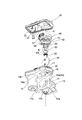
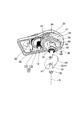
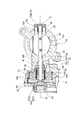
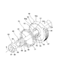
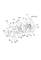
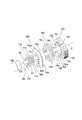
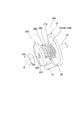
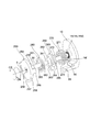
- FIG. 1 is an external perspective view showing an embodiment of a throttle device according to the present invention. It is a disassembled perspective view of the throttle apparatus which concerns on one Embodiment. It is a disassembled perspective view of the throttle apparatus which concerns on one Embodiment. 1 is a perspective view showing a state in which a body and a drive source are removed in a throttle device according to an embodiment. In the throttle apparatus which concerns on one Embodiment, it is a perspective view which shows the state which removed the cover and the default mechanism. In the throttle apparatus which concerns on one Embodiment, it is a fragmentary sectional view in the surface containing the axis line of a valve shaft.
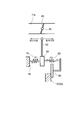
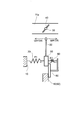
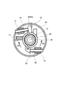
- FIG. 6 is an operation diagram showing a state in which the throttle valve is in a fully closed position in the throttle device according to the present invention.
- FIG. 6 is an operation diagram showing a state where the throttle valve is in a default position in the throttle device according to the present invention.
- FIG. 5 is an operation diagram showing a state where the throttle valve is in a fully open position in the throttle device according to the present invention.
- FIG. 5 is a perspective view showing another embodiment of a default mechanism included in the throttle device of the present invention, with a body partially cut away.
- FIG. 17 is an exploded perspective view showing a part of the body, a valve shaft, a first rotating body, a second rotating body, a first biasing spring, and a second biasing spring in the default mechanism shown in FIG. 16.
- FIG. 17 is an exploded perspective view showing a valve shaft, a first rotating body, a second rotating body, a first biasing spring, and a second biasing spring in the default mechanism shown in FIG. 16.
- FIG. 17 is an exploded perspective view showing a valve shaft, a first rotating body, a second rotating body, a first biasing spring, and a second biasing spring in the default mechanism shown in FIG. 16.
- FIG. 10 is a perspective view showing still another embodiment of a default mechanism included in the throttle device of the present invention, with a body partially cut away.
- FIG. 20 is an exploded perspective view illustrating a part of the body, a valve shaft, a first rotating body, a second rotating body, a first biasing spring, and a second biasing spring in the default mechanism illustrated in FIG. 19.
- FIG. 20 is an exploded perspective view showing a valve shaft, a first rotating body, a second rotating body, a first biasing spring, and a second biasing spring in the default mechanism shown in FIG. 19.
- a throttle device is assembled in an intake system of an engine mounted on a vehicle or the like and adjusts an intake air amount flowing in an intake passage.
- a valve shaft 30 having an axis S As shown in FIGS. 20, a valve shaft 30 having an axis S, a throttle valve 40 that rotates together with the valve shaft 30 to open and close the intake passage, a default mechanism M, a drive mechanism D, and a position sensor PS.
- the default mechanism M is to position the throttle valve 40 at a default position between the fully closed position and the fully opened position and with an opening larger than the idle position.
- the default mechanism M is a rotary gear 50 as a first rotary body and a second rotary body. Rotating holder 60, first urging spring 70, second urging spring 80, and adjusting screw 90 as a defining portion.
- the drive mechanism D exerts a drive force on the valve shaft 30 and includes a drive source 100, a drive gear 110, and a two-stage gear 120.
- the position sensor PS is a magnetic sensor that detects the rotation angle position of the valve shaft 30, that is, the opening degree of the throttle valve 40 in a non-contact manner, and includes a detection unit PS1 and a rotor unit PS2.
- the detection unit PS1 includes a stator and a Hall element embedded in the cylindrical portion 24 of the cover 20.
- the rotor part PS2 includes an armature and a yoke embedded in a cylindrical member joined to the joint part 59 of the rotary gear 50.
- the body 10 is formed of a resin material or a metal material such as aluminum, and houses the cylindrical portion 11, the connection flanges 12 a and 12 b, the valve shaft hole 13 through which the valve shaft 30 passes, the default mechanism M, and a part of the drive mechanism D.
- a shaft 18 is provided.
- the cylindrical portion 11 defines a cylindrical intake passage 11a through which intake air flows.
- the connection flanges 12a and 12b are connected to the middle of a passage member forming an intake system of the engine so that intake air flows through the intake passage 11a.
- the valve shaft hole 13 includes a shaft hole 13a through which the valve shaft 30 is rotatably passed, a seal hole 13b into which a seal SR that seals the outer periphery of the valve shaft 30 is fitted, and a bearing B that rotatably supports the valve shaft 30. Is formed of a bearing hole 13c into which the cap C is fitted and a fitting hole 13d into which the cap C is fitted.
- the recess 14 includes a flat wall portion 14a adjacent to the outer wall of the cylindrical portion 11 and perpendicular to the axis S, an annular wall portion 14b surrounding the flat wall portion 14a, and a portion of the flat wall portion 14a around the axis S.
- An accommodation recess 14c and an annular recess 14d, an end surface 14e, a latching portion 14f as a third latching portion, and a fitting hole 14g are formed.
- the housing recess 14c is formed on the inner side closer to the intake passage 11a than the annular recess 14d in the axis S direction, and is rotatable around the axis S in a predetermined angle range with the rotary holder 60 being moved inward in the axis S direction. Accommodate. That is, by arranging the rotary holder 60 in the housing recess 14 c of the body 10, it is possible to achieve the integration of parts in the direction of the axis S of the valve shaft 30, the narrowing of the device, and the miniaturization.
- the annular recessed portion 14d receives a part of the coil portion 71 of the first biasing spring 70 so as to approach the inside in the axis S direction. That is, a part of the coil portion 71 of the first urging spring 70 is received in the annular recess 14 d of the body 10, whereby the width of the device in the direction of the axis S of the valve shaft 30 can be reduced.
- the end face 14e is formed so as to oppose the rotation holder 60 rotatably supported by the valve shaft 30 in the axis S direction.
- the hooking portion 14f is formed on a part of the peripheral wall of the annular recess 14d so as to hook the other end 73 of the first biasing spring 70.
- the concave portion 15 has a bottomed cylindrical shape that extends in parallel with the axis S and opens at the flat wall portion 14a to accommodate the drive source 100.
- the screw hole 16 penetrates from the outside of the body 10 to the wall surface of the housing recess 14c so that the adjustment screw 90 can be screwed in from outside. That is, since the adjustment screw 90 is employed as the defining portion, the default position can be easily and accurately set to the position according to the request by appropriately adjusting the screwing amount of the adjustment screw 90.
- the screw hole 17 penetrates the annular wall portion 14b that forms a part of the body 10 so that the adjustment screw 91 can be screwed in from outside. That is, since the adjustment screw 91 is employed as the fully closed stopper, the fully closed position can be easily adjusted by appropriately adjusting the screwing amount of the adjustment screw 91.
- the support shaft 18 is disposed so as to extend in parallel with the axis S by a metal material or the like, and is fitted and fixed in a fitting hole 14g provided in the flat wall portion 14a.
- the support shaft 18 is firmly supported by a tip end portion of the support shaft 18 fitted in the fitting hole 23 of the cover 20 while the two-stage gear 120 is rotatably supported.
- the cover 20 is formed of a resin material or a metal material such as aluminum, and is joined to the annular wall portion 14b of the body 10 so as to cover the recess 14.
- the cover 20 includes a connector 21 including terminals for electrically connecting the drive source 100 and the position sensor PS to the outside, two female terminals 22 guided from the connector 21 and coupled to the drive source 100, and a tip end portion of the support shaft 18.
- a fitting hole 23 to be fitted and a cylindrical part 24 having a center on the axis S and having the detection part PS1 of the position sensor PS embedded therein are provided.
- the two female terminals 22 are detachably fitted to and electrically connected to the two male terminals 103 of the drive source 100 housed in the recess 15.
- the valve shaft 30 is formed of a metal material or the like so as to extend in the direction of the axis S in a circular cross section, and has a fixing portion 31 that fixes the rotary gear 50 on one end side, a slit 32 and a screw that fits the throttle valve 40 in a substantially central region. A hole 33 is provided.
- the valve shaft 30 is disposed through the valve shaft hole 13 of the body 10, and the throttle valve 40 fitted in the slit 32 is fastened by the screw b1 so that the throttle valve 40 can be freely opened and closed. .
- the throttle valve 40 is formed in a substantially disk shape with a metal material or the like, and includes a circular hole 41 through which the screw b1 is passed.
- the throttle valve 40 is disposed so as to open and close the intake passage 11a after the valve shaft 30 is passed through the valve shaft hole 13 and then passed through the slit 32 and fixed to the valve shaft 30 by the screw b1.
- the throttle valve 40 fully closes and fully opens the intake passage 11a according to the rotation of the valve shaft 30, and opens the intake passage 11a to the respective opening degrees corresponding to the idle position and the default position. Yes.
- the rotating gear 50 is made of a resin material or the like, and rotates integrally with the valve shaft 30 and is given a driving force by the driving mechanism D.
- the rotating gear 50 includes a fixed portion 51, a concave portion 52, a concave portion 53, a latch portion 54 as a first latch portion, a latch portion 55 as a second latch portion, a projection 56 as a first engagement portion, A tooth part 57 as a transmission part, a contact part 58, and a joint part 59 for joining the rotor part PS2 of the position sensor PS are provided.
- the fixing portion 51 is formed so as to be fitted and fixed to the fixing portion 31 of the valve shaft 30.
- the recess 52 is formed so as to be recessed in the direction of the axis S with respect to the tooth row 57, is formed in an annular shape centering on the axis S so as to face the body 10, and the coil portion 71 of the first biasing spring 70. Accept some.
- the concave portion 53 is formed so as to be recessed in the direction of the axis S with respect to the tooth row 57, is formed in an annular shape centering on the axis S so as to face the rotary holder 60, and the coil portion 81 of the second biasing spring 80. Accept some.
- the coil portion 71 of the first biasing spring 70 is received in the recess 52, and the coil portion 81 of the second biasing spring 80 is received in the recess 53. Therefore, the first urging spring 70 and the second urging spring 80 and the rotation gear 50 can be arranged so as to overlap in the axis S direction of the valve shaft 30. Therefore, the device can be narrowed in the direction of the axis S of the valve shaft 30.
- the latching portion 54 is formed by notching a part of the outer peripheral wall 52 a that defines the recess 52 so as to latch the one end 72 of the first biasing spring 70.
- the latching portion 55 is formed by cutting out a part of the outer peripheral wall 53 a that defines the recess 53 in order to latch the one end portion 82 of the second urging spring 80.
- the protrusion 56 is formed to be adjacent to the outside of the outer peripheral wall 53a and to extend in the axis S direction so as to be releasably engaged with the protrusion 64 as the second engagement portion of the rotary holder 60 around the axis S.
- the protrusion 56 can engage with the protrusion 64 of the rotation holder 60 when the rotation gear 50 rotates in the valve opening direction OR, and the protrusion of the rotation holder 60 when the rotation gear 50 rotates in the valve closing direction CR. It can come off from 64.
- the tooth row 57 is formed in an arc shape over a predetermined angle range, and meshes with the small gear 122 of the two-stage gear 120 so that the driving force of the driving mechanism D is exerted on the valve shaft 30.
- the contact portion 58 is formed at the end portion of the tooth row 57 and contacts the adjustment screw 91 provided on the body 10 so as to be detachable around the axis S. That is, the rotation gear 50 rotates in the valve closing direction CR, and the contact portion 58 contacts the adjustment screw 91, so that the rotation of the rotation gear 50 and the valve shaft 30 is limited, and the throttle valve 40 is brought into the fully closed position.
- the joint portion 59 is formed on the side facing the cylindrical portion 24 of the cover 20 so as to fit and fix the rotor portion PS2 of the position sensor PS.
- the rotation holder 60 is formed of a resin material or the like, and can rotate relative to the valve shaft 30 and engages with an adjustment screw 90 as a defining portion when rotating in the valve closing direction CR so as to move in the valve closing direction CR.
- the above rotation is limited.
- the rotary holder 60 abuts against a cylindrical hole 61, an annular groove 62, a latching portion 63 as a fourth latching portion, a protrusion 64 as a second engagement portion, an end surface 65, and an adjustment screw 90 as a defining portion.
- a contact portion 66 is provided.
- the valve shaft 30 is rotatably fitted in the cylindrical hole 61. That is, the rotation holder 60 is supported so as to be rotatable relative to the valve shaft 30 by passing the valve shaft 30 through the cylindrical hole 61.
- the annular groove 62 is formed around the cylindrical hole 61 so as to receive a part of the coil portion 81 of the second urging spring 80.
- the latching portion 63 is formed by hollowing a part of the outer peripheral wall of the annular groove 62 into a groove shape so as to latch the other end 83 of the second urging spring 80.
- the protrusion 64 is formed so as to extend in the direction of the axis S so as to be releasably engaged with the protrusion 56 as the first engaging portion of the rotary gear 50 around the axis S.
- the protrusion 64 can be engaged with the protrusion 56 of the rotation gear 50 when the rotation holder 60 rotates in the valve closing direction CR, and the protrusion of the rotation gear 50 when the rotation holder 60 rotates in the valve opening direction OR. It can come off from 56.
- the end face 65 comes into contact with the inner ring of the bearing B fitted to the body 10.
- the abutting portion 66 abuts on the adjustment screw 90 around the axis S so as to be detachable.
- the rotation holder 60 is rotatably supported by the valve shaft 30 and is accommodated in the accommodation recess 14 c of the body 10, and the second urging spring 80 is accommodated and held in the annular groove 62.
- the rotation holder 60 by arranging the rotation holder 60 in the housing recess 14 c of the body 10, it is possible to achieve the integration of parts in the axis S direction of the valve shaft 30, the narrowing of the device, and the miniaturization.
- the coil portion 81 of the second urging spring 80 is received in the annular groove 62 of the rotation holder 60, the second urging spring 80 and the rotation holder 60 are arranged so as to overlap in the direction of the axis S of the valve shaft 30. The width in the axis S direction of the valve shaft 30 can be reduced.
- the first biasing spring 70 is a large-diameter torsion coil spring that is interposed between the rotating gear 50 and the body 10, and includes a coil portion 71, one end portion 72, and the other end portion 73.
- the first urging spring 70 is arranged around the valve shaft 30 and around the second urging spring 80 held by the rotation holder 60, and the coil portion 71 is formed in the annular recess 14 d of the body 10 and the rotation gear 50.
- the one end 72 is hooked on the hooking portion 54 of the rotating gear 50 and the other end 73 is hooked on the hooking portion 14 f of the body 10.
- the first biasing spring 70 urges the rotation gear 50 and the valve shaft 30 to rotate in the valve closing direction CR with respect to the body 10.
- the second biasing spring 80 is a small-diameter torsion coil spring interposed between the rotating gear 50 and the rotating holder 60, and includes a coil portion 81, one end portion 82, and the other end portion 83.
- the second urging spring 80 is arranged around the valve shaft 30 and held by the rotary holder 60, and the coil portion 81 is received in the annular groove 62 of the rotary holder 60 and the concave portion 53 of the rotary gear 50. In this state, one end 82 is hooked on the hook 55 of the rotary gear 50 and the other end 83 is hooked on the hook 63 of the rotary holder 60.
- the second biasing spring 80 pulls the rotation gear 50 in the valve opening direction OR and the rotation holder 60 in the valve closing direction CR, respectively, and causes the protrusion 56 of the rotation gear 50 and the protrusion 64 of the rotation holder 60 to move. Rotating bias is applied to engage.
- the second urging spring 80 exerts a rotation urging force so as to maintain the engagement between the protrusion 56 and the protrusion 64 when the driving force of the drive source 100 is not applied.
- the first urging spring 70 urges the rotation gear 50 to rotate in the valve closing direction CR.
- the rotating holder 60 that rotates in the rotational direction is rotated in the valve closing direction CR and is urged to rotate so that the abutment portion 66 abuts against the adjustment screw 90 of the body 10. In this way, when the contact portion 66 contacts the adjustment screw 90, the throttle valve 40 is positioned at the default position.
- the driving source 100 applies a rotational driving force to the valve shaft 30 and, for example, a DC motor or the like is applied.
- the drive source 100 includes a main body 101, a rotating shaft 102, and two male terminals 103.
- the main body 101 is fitted into the concave portion 15 of the body 10 and is fixed by the screw b2.
- a driving gear 110 is fitted and fixed to the rotating shaft 102.
- the two male terminals 103 are connected to the two female terminals 22 when the cover 20 is connected to the body 10.
- the drive gear 110 is a small-diameter gear and is placed in the recess 14 of the body 10 by being fitted and fixed to the rotation shaft 102 of the drive source 100.
- the two-stage gear 120 includes a large-diameter gear 121 that meshes with the drive gear 110 and a small-diameter gear 122 that meshes with the tooth row 57 of the drive gear 50 on the same axis.
- the two-stage gear 120 is rotatably fitted on and supported by the support shaft 18 fixed to the body 10.
- the driving mechanism D including the driving source 100, the driving gear 110, and the two-stage gear 120
- the driving gear 110, the large diameter gear 121, the small diameter gear 122, and the tooth row 57 are interposed.
- the drive gear 50 and the valve shaft 30 are rotated in the valve closing direction CR, and the throttle valve 40 is rotated in the direction of closing the intake passage 11a.
- the drive gear 50 and the valve shaft 30 are rotated in the valve opening direction OR via the drive gear 110, the large diameter gear 121, the small diameter gear 122, and the tooth row 57, and the throttle The valve 40 rotates in a direction to open the intake passage 11a.
- the first urging spring 70 and the second urging spring 80 exert urging forces F1 and F2 as shown in FIG.
- the first biasing spring 70 always exerts a biasing force F ⁇ b> 1 on the valve shaft 30 in the valve closing direction CR. That is, the first urging spring 70 has the smallest urging force f1c at the fully closed position cp, the largest urging force f1o at the fully open position op, and the urging force f1i (> f1c) at the idle position ip.
- the biasing force f1d (f1i ⁇ f1d ⁇ f1o) is applied at the default position dp.
- the second biasing spring 80 does not exert a biasing force on the valve shaft 30 between the default position dp and the fully open position op, and applies a biasing force F2 in the valve opening direction OR at an opening position smaller than the default position dp. It has come to affect. That is, the second urging spring 80 exerts the largest urging force f2c at the fully closed position cp and the urging force f2i ( ⁇ f2c) at the idle position ip with respect to the valve shaft 30, and from the default position dp to the fully open position op. There is no urging force between them.
- the urging force (F2-F1) acts on the valve shaft 30 in the valve opening direction OR between the fully closed position cp and the default position ip, and between the default position dp and the fully opened position op.
- the force F1 acts in the valve closing direction CR.
- the second biasing spring 80 exerts a biasing force f2d on the rotating gear 50 that is greater than the biasing force f1d of the first biasing spring 70 at the default position dp where the rotation of the rotary holder 60 is restricted by the adjusting screw 90.
- the rotary gear 50 is set to be pulled toward the rotary holder 60. According to this, even when the rotation source 50 tries to rotate in the valve closing direction CR due to the intake pressure or the like when the drive source 100 is inactive, the urging force f2d of the second urging spring 80 is the first urging spring 70.
- the engagement between the projection 56 of the rotary gear 50 and the projection 64 of the rotary holder 60 is maintained, and the throttle valve 40 can be reliably stopped and positioned at the default position dp. Even if the urging force f2d and the urging force fd1 antagonize at the same value, the engagement state of the protrusion 56 of the rotating gear 50 and the protrusion 64 of the rotating holder 60 can be maintained.
- the rotating gear 50 is rotated by the rotating holder 60 as shown in FIGS.
- Driving in a state in which an urging force (F2-F1) limited by the adjusting screw 90 and subtracting the urging force F1 of the first urging spring 70 from the urging force F2 of the second urging spring 80 acts in the valve opening direction OR It is rotated by the driving force of the source 100.
- the driving force of the driving source 100 is applied in the region from the default position to the fully open position
- the urging force F2 of the second urging spring 80 is applied to the rotating gear 50 as shown in FIGS.
- the first urging spring 70 is rotated together with the rotary holder 60 by the driving force of the driving source 100.
- the urging force F1 of the first urging spring 70 acts on the rotating gear 50 as shown in FIGS.
- the rotation holder 60 is rotated in the valve closing direction CR, and the rotation of the rotation holder 60 is limited by the adjustment screw 90, thereby stopping at the default position.
- the rotating gear 50 starts from the biasing force F2 of the second biasing spring 80 as shown in FIGS.
- the urging force (F2-F1) obtained by subtracting the urging force F1 of the one urging spring 70 acts in the valve opening direction OR, engages with the rotary holder 60 limited by the adjusting screw 90, and stops at the default position.
- the rotating gear 50 that is, the throttle valve 40 is automatically positioned at the default position as shown in FIG.
- the first urging spring 70 and the second urging spring 80 are disposed around the valve shaft 30, it is possible to achieve the integration of parts and the miniaturization of the apparatus.
- the first urging spring 70 and the second urging spring 80 are arranged in a nested manner around the axis S of the valve shaft 30.
- the parts can be integrated, and the width and size of the apparatus in the direction of the axis S of the valve shaft 30 can be reduced.
- the first biasing spring 70 and the second biasing spring 80 are arranged so as to be covered between the rotation gear 50 and the wall portion of the body 10, interference with other parts and the biting of foreign matter are caused. And the like, and a predetermined biasing force can be exerted.
- the rotation gear 50, the rotation holder 60, the first urging spring 70, the second urging spring 80, and the adjusting screw 90 as the defining portion of the body 10 are employed.
- the default position can be easily set and adjusted, and parts can be integrated and the apparatus can be downsized.
- the default mechanism M is disposed in the concave portion 14 of the body 10
- the position sensor PS is disposed in the concave portion 14 and the cover 20 that covers the concave portion 14. That is, the default mechanism D and the position sensor PS are disposed on one side of the body 10.
- the engine When the engine is switched on in this stopped state, the engine starts smoothly.
- the drive source 100 When the engine is in an idle operation state according to the accelerator or throttle operation on the vehicle side, the drive source 100 is unidirectional. Rotating, throttle valve 40 is positioned at an idle position that is smaller than the default position shown in FIG. 14 and larger than the fully closed position shown in FIG. At this time, the rotation of the rotary holder 60 is restricted by the contact portion 66 coming into contact with the adjustment screw 90, and the rotation gear 50 is attached to the second urging spring 80 by the projection 56 being detached from the projection 64. The valve rotates in the valve closing direction CR against the force and is held at the idle position.
- the drive source 100 rotates in the other direction, and the throttle valve 40 goes from the idle position to the default position, It is rotated toward the fully open position.
- the rotation gear 50 rotates in the valve opening direction OR, and as shown in FIG. 14, the protrusion 56 engages with the protrusion 64 at the default position, and between the default position and the fully open position, FIG.
- the rotating gear 50 and the rotating holder 60 rotate together in the valve opening direction OR.
- the drive source 100 rotates in one direction, and the throttle valve 40 As shown in FIG. 15 to FIG. 14, the rotation is performed from the fully open position toward the default position.
- the rotation gear 50 and the rotation holder 60 rotate together in the valve closing direction CR in a state where the engagement between the protrusion 56 and the protrusion 64 is maintained.
- FIGS. 16 to 18 show another embodiment of the default mechanism included in the throttle device of the present invention.
- the same components as those in the above-described embodiment are denoted by the same reference numerals and described. Omitted. Further, the operation of the default mechanism is basically the same as that of the above-described embodiment, and thus the description thereof is omitted.
- the default mechanism M1 according to this embodiment includes a rotating gear 150 as a first rotating body, a rotating holder 160 as a second rotating body, a first biasing spring 170, a second biasing spring 180, and an adjusting screw as a defining portion. 90.
- the rotating gear 150 is made of a resin material or the like, and rotates integrally with the valve shaft 30 and is given a driving force by the driving mechanism D.
- the rotating gear 150 includes a fixed portion 151, a concave portion 152, a concave portion 153, a latching portion 154 as a first latching portion, a latching portion 155 as a second latching portion, a projection 156 as a first engagement portion, A tooth portion 157 as a transmission portion, a contact portion 158, and a joint portion 159 for joining the rotor portion PS2 of the position sensor PS are provided.
- the fixing portion 151 is the same as the above-described fixing portion 51
- the tooth row 157 is the same as the above-described tooth row 57
- the contact portion 158 is the same as the above-described contact portion 58
- the joint portion 159 is the same as that of the joint 59 described above.
- the recess 152 is formed so as to be recessed in the direction of the axis S with respect to the tooth row 157, and receives the cylindrical portion 162 of the rotary holder 160 in an annular shape centering on the axis S.
- the recess 153 is formed so as to be recessed in the direction of the axis S with respect to the tooth row 157, is formed in an annular shape centering on the axis S so as to face the body 10, and the coil portion 181 of the second biasing spring 180 is formed. Accept some.
- the cylindrical portion 162 that accommodates the coil portion 171 of the first biasing spring 170 is received by the concave portion 152, and the coil portion 181 of the second biasing spring 180 is concave. 153. Therefore, the first urging spring 170 and the second urging spring 180 and the rotation gear 150 can be arranged so as to overlap in the axis S direction of the valve shaft 30. Therefore, the device can be narrowed in the direction of the axis S of the valve shaft 30.
- the latching portion 154 is formed by notching a part of the outer peripheral wall 152 a that defines the recess 152 so as to latch the one end 172 of the first biasing spring 170.
- the latching portion 155 is formed so as to protrude in the direction of the axis S so as to latch the one end portion 182 of the second biasing spring 180.
- the protrusion 156 is formed so as to extend in the direction of the axis S so as to be releasably engaged with the protrusion 164 as the second engaging portion of the rotary holder 160 around the axis S.
- the protrusion 156 can be engaged with the protrusion 164 of the rotation holder 160 when the rotation gear 150 rotates in the valve opening direction OR, and the protrusion of the rotation holder 160 when the rotation gear 150 rotates in the valve closing direction CR. 164 can be removed.
- the rotation holder 160 is formed of a resin material or the like and can rotate relative to the valve shaft 30 and engages with an adjustment screw 90 as a defining portion when rotating in the valve closing direction CR so that it rotates in the valve closing direction CR.
- the above rotation is limited.
- the rotation holder 160 includes a cylindrical hole 161, an annular groove 162a defined inside the cylindrical portion 162, a latching portion 163 as a fourth latching portion, a projection 164 as a second engagement portion, a notch 165, a regulation.
- a contact portion 166 that contacts the adjustment screw 90 as a portion is provided.
- the valve shaft 30 is rotatably fitted in the cylindrical hole 161. That is, the rotation holder 160 is supported rotatably relative to the valve shaft 30 by passing the valve shaft 30 through the cylindrical hole 161.
- the cylindrical portion 162 is formed so as to be received in the concave portion 152 of the rotating gear 150, and defines an annular groove 162 a inside and around the cylindrical hole 161.
- the annular groove 162 a is formed so as to receive a part of the coil portion 171 of the first biasing spring 170.
- the latching portion 163 is formed to project in the axis S direction so as to latch the other end portion 183 of the second biasing spring 180.
- the protrusion 164 is formed to extend in the direction of the axis S so as to be detachably engaged with the protrusion 156 of the rotary gear 150 around the axis S.
- the protrusion 164 can engage with the protrusion 156 of the rotation gear 150 when the rotation holder 160 rotates in the valve closing direction CR, and the protrusion of the rotation gear 150 when the rotation holder 160 rotates in the valve opening direction OR. 156 can be removed.
- the notch 165 is formed to pass through the one end 172 of the first biasing spring 170 and be movably received within a predetermined range around the axis S, and to be guided to the latching portion 154 of the rotating gear 150.
- the contact portion 166 is the same as the contact portion 66 described above.
- the rotary holder 160 is rotatably supported by the valve shaft 30 and is accommodated in the accommodating recess 14c of the body 10, and the first biasing spring 170 is accommodated and held in the annular groove 162a. According to this, since the coil portion 171 of the first biasing spring 170 is received in the annular groove 162a of the rotary holder 160, the first biasing spring 70 and the rotary holder 160 are overlapped in the axis S direction of the valve shaft 30.
- the valve shaft 30 can be narrowed in the direction of the axis S.
- the first biasing spring 170 is a small-diameter torsion coil spring interposed between the rotating gear 150 and the body 10, and includes a coil portion 171, one end portion 172, and the other end portion 173.
- the first biasing spring 170 is disposed around the valve shaft 30 and inside the second biasing spring 180 disposed around the cylindrical portion 162 of the rotation holder 160, and the coil portion 171 is disposed on the rotation holder 160.
- one end 172 is hooked on the hooking portion 154 of the rotating gear 150
- the other end 173 is hooked on the hooking portion 14f of the body 10.
- the first biasing spring 170 rotates and biases the rotation gear 150 and the valve shaft 30 in the valve closing direction CR with respect to the body 10.
- the second urging spring 180 is a large-diameter torsion coil spring interposed between the rotation gear 150 and the rotation holder 160 and includes a coil portion 181, one end portion 182, and the other end portion 183.
- the second biasing spring 180 has the coil portion 181 disposed around the valve shaft 30 and around the cylindrical portion 162 of the rotary holder 160, and one end portion 182 is latched by the latching portion 155 of the rotary gear 150.
- the other end 183 is hooked on the hook 163 of the rotary holder 160.
- the second biasing spring 180 pulls the rotation gear 150 in the valve opening direction OR and the rotation holder 160 in the valve closing direction CR, and causes the protrusion 156 of the rotation gear 150 and the protrusion 164 of the rotation holder 160 to move. Rotating bias is applied to engage.
- the second urging spring 180 exerts a rotation urging force so as to maintain the engagement between the protrusion 156 and the protrusion 164 when the driving force of the driving source 100 is not applied.
- the first urging spring 170 urges the rotation gear 150 to rotate in the valve closing direction CR.
- the rotating holder 160 that rotates in the clockwise direction is rotated in the valve closing direction CR and is urged to rotate so that the abutting portion 166 contacts the adjusting screw 90 of the body 10. In this manner, when the contact portion 166 contacts the adjustment screw 90, the throttle valve 40 is positioned at the default position.
- the first biasing spring 170 is disposed in a nested manner around the axis S inside the second biasing spring 180. Therefore, it is possible to achieve the integration of parts and the miniaturization of the device in the direction of the axis S.
- the default position can be easily set and adjusted, and parts can be consolidated and the apparatus can be downsized.
- the vehicle equipped with the engine equipped with this throttle device the vehicle is in an operating state in which the vehicle can be self-propelled in the same manner as described above, and a safe retreat operation can be performed. Further, as described above, since the default position can be maintained at a predetermined position with high accuracy, the safety can be further improved as compared with the conventional technique in which variation in the default position is a concern.
- FIGS. 19 to 21 show still another embodiment of the default mechanism included in the throttle device of the present invention.
- the same components as those in the above-described embodiment will be described with the same reference numerals. Is omitted. Further, the operation of the default mechanism is basically the same as that of the above-described embodiment, and thus the description thereof is omitted.
- the default mechanism M2 according to this embodiment includes a rotating gear 250 as a first rotating body, a rotating holder 260 as a second rotating body, a first biasing spring 270, a second biasing spring 280, and an adjusting screw as a defining portion. 90.
- the rotation gear 250 is formed of a resin material or the like, and rotates integrally with the valve shaft 30 and is given a driving force by the driving mechanism D.
- the rotating gear 250 includes a fixed portion 251, a concave portion 252, a concave portion 253, a hook portion 254 as a first hook portion, a hook portion 255 as a second hook portion, a protrusion 256 as a first engagement portion, A tooth portion 257 as a transmission portion, a contact portion 258, and a joint portion 259 for joining the rotor portion PS2 of the position sensor PS are provided.
- the fixing portion 251 is the same as the above-described fixing portion 51
- the tooth row 257 is the same as the above-described tooth row 57
- the contact portion 258 is the same as the above-described contact portion 58
- the joint portion 259. Is the same as that of the joint 59 described above.
- the recess 252 is formed so as to be recessed in the direction of the axis S with respect to the tooth row 257, and receives the cylindrical portion 262 of the rotary holder 260 in an annular shape centering on the axis S.
- the recess 253 is formed so as to be recessed in the direction of the axis S with respect to the tooth row 257, is formed in an annular shape centering on the axis S so as to face the body 10 side, and the coil portion 281 of the second biasing spring 280. Accept some.
- the cylindrical portion 262 of the rotary holder 260 is received in the recess 252 and the coil portion 281 of the second urging spring 280 is received in the recess 253. Therefore, the rotation holder 260, the second urging spring 280, and the rotation gear 250 can be arranged close to each other or overlap in the direction of the axis S of the valve shaft 30. Therefore, the device can be narrowed in the direction of the axis S of the valve shaft 30.
- the latching portion 254 is formed to project in the direction of the axis S so as to latch the one end portion 272 of the first biasing spring 270.
- the latching portion 255 is formed to protrude in the direction of the axis S so as to latch the one end 282 of the second biasing spring 280.
- the protrusion 256 is formed to extend in the direction of the axis S in the same manner as the hook 254 so as to be releasably engaged with the protrusion 264 as the second engagement portion of the rotary holder 260 around the axis S. Yes.
- the protrusion 256 can be engaged with the protrusion 264 of the rotation holder 260 when the rotation gear 250 rotates in the valve opening direction OR, and the protrusion of the rotation holder 260 when the rotation gear 250 rotates in the valve closing direction CR. H.264 can be detached.
- the rotation holder 260 is formed of a resin material or the like, and can rotate relative to the valve shaft 30 and engages with the adjusting screw 90 as a defining portion when rotating in the valve closing direction CR, so that it rotates in the valve closing direction CR.
- the above rotation is limited.
- the rotation holder 260 contacts the cylindrical hole 261, the cylindrical portion 262, the latching portion 263 as the fourth latching portion, the projection 264 as the second engagement portion, the cylindrical portion 265, and the adjustment screw 90 as the defining portion.
- a contact portion 266 is provided.
- the valve shaft 30 is rotatably fitted in the cylindrical hole 261. That is, the rotation holder 260 is supported so as to be rotatable relative to the valve shaft 30 by passing the valve shaft 30 through the cylindrical hole 261.
- the cylindrical portion 262 is received in the concave portion 252 of the rotating gear 250.
- the latching portion 263 is formed to project in the direction of the axis S so as to latch the other end portion 283 of the second biasing spring 280.
- the protrusion 264 is formed to extend in the direction of the axis S so as to be detachably engaged with the protrusion 256 of the rotary gear 250 around the axis S.
- the protrusion 264 can engage with the protrusion 256 of the rotation gear 250 when the rotation holder 260 rotates in the valve closing direction CR, and the protrusion of the rotation gear 250 when the rotation holder 260 rotates in the valve opening direction OR. It is possible to detach from 256.
- the cylindrical portion 265 is formed so that the coil portion 271 of the first urging spring 270 is disposed around the cylindrical portion 265 and the end surface thereof faces the accommodating recess 14 c of the body 10.
- the contact part 266 is the same as the contact part 66 described above.
- the rotation holder 260 is rotatably supported by the valve shaft 30 and is accommodated in the accommodation recess 14 c of the body 10 with the first biasing spring 270 interposed therebetween.
- the first biasing spring 270 and the rotation holder 260 can be arranged close to each other or overlap in the direction of the axis S of the valve shaft 30, and the width of the valve shaft 30 in the direction of the axis S can be reduced. Can be achieved.
- the first biasing spring 270 is a torsion coil spring having a predetermined diameter that is interposed between the rotating gear 250 and the body 10, and includes a coil portion 271, one end portion 272, and the other end portion 273.
- the first urging spring 270 has the coil portion 271 arranged around the valve shaft 30 and around the cylindrical portion 265 of the rotary holder 260, and one end portion 272 is hooked on the hook portion 254 of the rotary gear 250.
- the other end portion 273 is hooked on the hooking portion 14 f of the body 10.
- the first biasing spring 270 rotationally biases the rotation gear 250 and the valve shaft 30 in the valve closing direction CR with respect to the body 10.
- the second biasing spring 280 is a torsion coil spring that is interposed between the rotary gear 250 and the rotary holder 260 and has the same diameter as the first biasing spring 270, and includes a coil portion 281, one end portion 282, and the other end portion 283. ing.
- the coil portion 281 is disposed around the valve shaft 30 and around the cylindrical portion 262 of the rotary holder 260, and the one end portion 282 is hooked on the hook portion 255 of the rotary gear 250.
- the other end 283 is hooked on the hook 263 of the rotary holder 260.
- the second biasing spring 280 pulls the rotation gear 250 in the valve opening direction OR and the rotation holder 260 in the valve closing direction CR, and causes the protrusion 256 of the rotation gear 250 and the protrusion 264 of the rotation holder 260 to move. Rotating bias is applied to engage.
- the second urging spring 280 exerts a rotation urging force so as to maintain the engagement between the protrusion 256 and the protrusion 264 when the driving force of the driving source 100 is not applied.
- the first urging spring 270 urges the rotation gear 250 to rotate in the valve closing direction CR.
- the rotating holder 260 that rotates in the clockwise direction rotates in the valve closing direction CR and is urged to rotate so that the abutting portion 266 abuts against the adjusting screw 90 of the body 10. In this manner, when the contact portion 266 contacts the adjustment screw 90, the throttle valve 40 is positioned at the default position.
- the first urging spring 170 and the second urging spring 180 have the same diameter and are disposed adjacent to each other in the axis S direction. Therefore, the size of the apparatus can be reduced by suppressing the dimension in the radial direction perpendicular to the axis S.
- the default position can be easily set and adjusted, and parts can be consolidated and the apparatus can be downsized.
- the vehicle equipped with the engine equipped with this throttle device the vehicle is in an operating state in which the vehicle can be self-propelled in the same manner as described above, and a safe retreat operation can be performed. Further, as described above, since the default position can be maintained at a predetermined position with high accuracy, the safety can be further improved as compared with the conventional technique in which variation in the default position is a concern.
- the torsion coil spring is shown as the first urging spring and the second urging spring constituting the default mechanisms M, M1, and M2, but the present invention is not limited to this, and a desired urging force is applied. Other urging springs may be applied as long as they are effective.
- the rotation gear 50,150,250 and the rotation holder 60,160,260 were shown as a 1st rotary body and a 2nd rotary body, it is not limited to this, The rotary body which makes another form is shown. It may be adopted.
- the opening position where the vehicle can run is called the default position
- the mechanism that is positioned at the default position is called the default mechanism, but it is not limited to this name, and other names corresponding to the default position are limp.
- the home position or limp home opening is used, and the limp home mechanism may be used as another name corresponding to the default mechanism.
- the drive mechanism D including the drive source 100, the drive gear 110, and the two-stage gear 120 is shown as the drive mechanism.
- the present invention is not limited to this, and other drive mechanisms may be adopted.
- the non-contact type position sensor PS is shown as the position sensor, the position sensor is not limited to this, and may be a contact type position sensor.
- the position sensor is not limited to the magnetic type but is based on other detection methods. A sensor may be employed.
- the throttle device of the present invention can be easily set and adjusted for the default position, and can be integrated into parts and downsized.
- the present invention can be applied as a throttle device for an engine, and is also useful for a vehicle equipped with another engine.
Landscapes
- Engineering & Computer Science (AREA)
- Chemical & Material Sciences (AREA)
- Combustion & Propulsion (AREA)
- Mechanical Engineering (AREA)
- General Engineering & Computer Science (AREA)
- Control Of Throttle Valves Provided In The Intake System Or In The Exhaust System (AREA)
Abstract
本発明のスロットル装置は、ボディ(10)、弁軸(30)、スロットル弁(40)、駆動源(100)、スロットル弁を全閉位置と全開位置の間のデフォルト位置に位置付けるデフォルト機構を備え、デフォルト機構は、デフォルト位置を規定するべくボディに設けられた規定部(90)、弁軸と一体的に回転する第1回転体(50)、弁軸と相対的に回転し得る共に規定部に係合して閉弁方向への回転が制限される第2回転体(60)、第1回転体とボディの間に介在して第1回転体を閉弁方向に付勢する第1付勢バネ(70)、第1回転体と第2回転体の間に介在して第1回転体を開弁方向にかつ第2回転体を閉弁方向に引き寄せて両者を係合させると共に駆動源の非作動時に両者の係合を維持するように付勢する第2付勢バネ(80)を含む。これにより、デフォルト位置の設定、調整を容易に行え、部品の集約化、装置の小型化を達成できる。
Description
本発明は、車両等に搭載されるエンジンの吸気系に配置されるスロットル装置に関し、特に、スロットル弁を車両が自走可能な開度位置(以下、デフォルト位置と称す)に位置付けるデフォルト機構を備えたスロットル装置に関する。
従来のスロットル装置としては、吸気通路を画定するボディ、ボディに回転自在に支持された弁軸、弁軸に固定されたスロットル弁、弁軸の端部に固定された歯車、歯車に回転駆動力を及ぼすアクチュエータ、スロットル弁を全閉位置と全開位置の間でアイドル開度よりも大きい開度のデフォルト位置に位置付けるデフォルト機構を備えたものが知られている(例えば、特許文献1を参照)。
このスロットル装置において、デフォルト機構は、歯車と一体的に回転する突起片、突起片と同一の幅をなすようにボディに形成されてデフォルト位置を規定する係止部、弁軸の周りにおいてボディと歯車の間に配置されると共に両端部が突起片及び係止部を挟み込むように組み付けられた捩りコイルバネを備えている。
このデフォルト機構においては、スロットル弁がデフォルト位置から開く方向に弁軸が回転すると、弁軸を閉弁方向に回転させてスロットル弁をデフォルト位置に戻すように、捩りコイルバネの一端部が突起片を回転付勢する。
一方、スロットル弁がデフォルト位置から閉じる方向に弁軸が回転すると、弁軸を開弁方向に回転させてスロットル弁をデフォルト位置に戻すように、捩りコイルバネの他端部が突起片を回転付勢する。
一方、スロットル弁がデフォルト位置から閉じる方向に弁軸が回転すると、弁軸を開弁方向に回転させてスロットル弁をデフォルト位置に戻すように、捩りコイルバネの他端部が突起片を回転付勢する。
しかしながら、上記のデフォルト機構では、係止部の幅寸法、捩りコイルバネの両端部の形状、突起片の幅寸法等によりデフォルト位置が規定される。したがって、デフォルト位置の精度を高めるには、これらの寸法及び形状等を高精度に管理する必要がある。
また、デフォルト位置は、ボディに形成される係止部の位置により規定されるため、エンジンの仕様に応じてデフォルト位置を変える場合は、要求される仕様ごとに対応させた係止部を有するボディを設定する必要がある。
さらに、デフォルト機構は、ボディの側部に配置されるため、できるだけ部品を集約して配置する必要がある。
また、デフォルト位置は、ボディに形成される係止部の位置により規定されるため、エンジンの仕様に応じてデフォルト位置を変える場合は、要求される仕様ごとに対応させた係止部を有するボディを設定する必要がある。
さらに、デフォルト機構は、ボディの側部に配置されるため、できるだけ部品を集約して配置する必要がある。
本発明は、上記の事情に鑑みて成されたものであり、その目的とするところは、デフォルト位置の設定及び調整を容易に行え、部品の集約化、装置の小型化を行えるスロットル装置を提供することにある。
本発明のスロットル装置は、吸気通路を画定するボディと、ボディに回転自在に支持された弁軸と、弁軸に固定されて吸気通路を開閉するスロットル弁と、弁軸に駆動力を及ぼす駆動源と、スロットル弁を全閉位置と全開位置の間のデフォルト位置に位置付けるデフォルト機構を備え、上記デフォルト機構は、デフォルト位置を規定するべくボディに設けられた規定部と、弁軸と一体的に回転する第1回転体と、弁軸と相対的に回転し得る共に規定部に係合して閉弁方向への回転が制限される第2回転体と、第1回転体とボディの間に介在して第1回転体を閉弁方向に付勢する第1付勢バネと、第1回転体と第2回転体の間に介在して第1回転体を開弁方向にかつ第2回転体を閉弁方向に引き寄せて両者を係合させると共に駆動源の非作動時に両者の係合を維持するように付勢する第2付勢バネを含む、構成となっている。
上記スロットル装置において、第2付勢バネの付勢力は、第2回転体の回転が規定部により制限されたデフォルト位置において、第1付勢バネの付勢力よりも大きく設定されている、構成を採用してもよい。
上記スロットル装置において、第1付勢バネ及び第2付勢バネは、弁軸の周りに配置された捩りコイルバネである、構成を採用してもよい。
上記スロットル装置において、第1付勢バネ及び第2付勢バネは、弁軸の軸線周りにおいて入れ子状に又は弁軸の軸線方向に隣接して配置されている、構成を採用してもよい。
上記スロットル装置において、ボディは、第2回転体を収容する収容凹部を含み、第2回転体は、弁軸に回転自在に支持されてボディの収容凹部に配置され、第1回転体は、ボディ及び第2回転体と対向するように配置されている、構成を採用してもよい。
上記スロットル装置において、第1回転体は、第1付勢バネの一端部を掛止する第1掛止部と、第2付勢バネの一端部を掛止する第2掛止部と、第2回転体と離脱可能に係合する第1係合部を含み、ボディは、第1付勢バネの他端部を掛止する第3掛止部を含み、第2回転体は、第2付勢バネの他端部を掛止する第4掛止部と、第1回転体の第1係合部と離脱可能に係合する第2係合部と、ボディの規定部に離脱可能に当接する当接部を含む、構成を採用してもよい。
上記スロットル装置において、ボディは、第1付勢バネのコイル部又は第2付勢バネのコイル部を受け入れる環状凹部を含み、第2回転体は、第1付勢バネのコイル部又は第2付勢バネのコイル部を受け入れる環状溝を含む、構成を採用してもよい。
上記スロットル装置において、第1回転体は、第1付勢バネのコイル部を受け入れる凹部、及び第2付勢バネのコイル部を受け入れる凹部を含む、構成を採用してもよい。
上記スロットル装置において、規定部は、ボディに螺合された調整ネジである、構成を採用してもよい。
上記スロットル装置において、第1回転体は、駆動源の駆動力が伝達される伝達部を含む、構成を採用してもよい。
上記スロットル装置において、スロットル弁の開度位置を検出する位置センサを含み、位置センサ及びデフォルト機構は、前記ボディの一側部に配置されている、構成を採用してもよい。
上記構成をなすスロットル装置によれば、デフォルト位置の設定及び調整を容易に行うことができ、部品の集約化、装置の小型化を達成することができる。
以下、本発明の実施の形態について、添付図面を参照しつつ説明する。
一実施形態に係るスロットル装置は、車両等に搭載されるエンジンの吸気系に組み付けられて吸気通路を流れる吸気量を調整するものであり、図1ないし図8に示すように、ボディ10、カバー20、軸線Sを有する弁軸30、弁軸30と一緒に回転して吸気通路を開閉するスロットル弁40、デフォルト機構M、駆動機構D、位置センサPSを備えている。
一実施形態に係るスロットル装置は、車両等に搭載されるエンジンの吸気系に組み付けられて吸気通路を流れる吸気量を調整するものであり、図1ないし図8に示すように、ボディ10、カバー20、軸線Sを有する弁軸30、弁軸30と一緒に回転して吸気通路を開閉するスロットル弁40、デフォルト機構M、駆動機構D、位置センサPSを備えている。
デフォルト機構Mは、スロットル弁40を全閉位置と全開位置の間でかつアイドル位置よりも大きい開度のデフォルト位置に位置付けるものであり、第1回転体としての回転ギヤ50、第2回転体としての回転ホルダ60、第1付勢バネ70、第2付勢バネ80、規定部としての調整ネジ90を備えている。
駆動機構Dは、弁軸30に駆動力を及ぼすものであり、駆動源100、駆動歯車110、二段歯車120を備えている。
位置センサPSは、弁軸30の回転角度位置、すなわち、スロットル弁40の開度を非接触にて検出する磁気式のセンサであり、検出部PS1、ロータ部PS2を備えている。
尚、検出部PS1は、カバー20の円柱部24に埋設されたステータ及びホール素子を含む。ロータ部PS2は、回転ギヤ50の接合部59に接合される円筒状部材に埋設されたアマチャ及びヨークを含む。
駆動機構Dは、弁軸30に駆動力を及ぼすものであり、駆動源100、駆動歯車110、二段歯車120を備えている。
位置センサPSは、弁軸30の回転角度位置、すなわち、スロットル弁40の開度を非接触にて検出する磁気式のセンサであり、検出部PS1、ロータ部PS2を備えている。
尚、検出部PS1は、カバー20の円柱部24に埋設されたステータ及びホール素子を含む。ロータ部PS2は、回転ギヤ50の接合部59に接合される円筒状部材に埋設されたアマチャ及びヨークを含む。
ボディ10は、樹脂材料又はアルミニウム等の金属材料により形成され、筒状部11、接続フランジ12a,12b、弁軸30を通す弁軸孔13、デフォルト機構M及び駆動機構Dの一部を収容する凹部14、駆動源110を収容する凹部15、規定部としての調整ネジ90を捩じ込むネジ孔16、全閉ストッパとしての調整ネジ91を捩じ込むネジ孔17、凹部14に固定された支軸18を備えている。
筒状部11は、吸気が流れる円筒状の吸気通路11aを画定している。
接続フランジ12a,12bは、吸気通路11a内を吸気が流れるように、エンジンの吸気系を形成する通路部材の途中に連結される。
弁軸孔13は、弁軸30が回転自在に通される軸孔13a、弁軸30の外周をシールするシールSRが嵌合されるシール孔13b、弁軸30を回転自在に支持する軸受Bが嵌合される軸受孔13c、キャップCが嵌合される嵌合孔13dにより構成されている。
接続フランジ12a,12bは、吸気通路11a内を吸気が流れるように、エンジンの吸気系を形成する通路部材の途中に連結される。
弁軸孔13は、弁軸30が回転自在に通される軸孔13a、弁軸30の外周をシールするシールSRが嵌合されるシール孔13b、弁軸30を回転自在に支持する軸受Bが嵌合される軸受孔13c、キャップCが嵌合される嵌合孔13dにより構成されている。
凹部14は、筒状部11の外壁に隣接し軸線Sに垂直な平坦壁部14a、平坦壁部14aの周りを囲む環状壁部14b、軸線Sの周りにおいて平坦壁部14aの一部を肉抜きして形成された収容凹部14c及び環状凹部14d、端面14e、第3掛止部としての掛止部14f、嵌合穴14gを備えている。
収容凹部14cは、軸線S方向において環状凹部14dよりも吸気通路11a寄りの内側に形成され、回転ホルダ60を軸線S方向の内側に寄せた状態で所定の角度範囲において軸線S回りに回転自在に収容する。
すなわち、回転ホルダ60がボディ10の収容凹部14cに配置されることにより、弁軸30の軸線S方向における部品の集約化、装置の幅狭化及び小型化を達成できる。
環状凹部14dは、第1付勢バネ70のコイル部71の一部を、軸線S方向の内側に寄せるように受け入れる。
すなわち、第1付勢バネ70のコイル部71の一部がボディ10の環状凹部14dに受け入れられることで、弁軸30の軸線S方向における装置の幅狭化を達成できる。
すなわち、回転ホルダ60がボディ10の収容凹部14cに配置されることにより、弁軸30の軸線S方向における部品の集約化、装置の幅狭化及び小型化を達成できる。
環状凹部14dは、第1付勢バネ70のコイル部71の一部を、軸線S方向の内側に寄せるように受け入れる。
すなわち、第1付勢バネ70のコイル部71の一部がボディ10の環状凹部14dに受け入れられることで、弁軸30の軸線S方向における装置の幅狭化を達成できる。
端面14eは、弁軸30により回転自在に支持された回転ホルダ60と軸線S方向において対向するように形成されている。
掛止部14fは、第1付勢バネ70の他端部73を掛止するべく、環状凹部14dの周壁の一部に形成されている。
凹部15は、駆動源100を収容するべく、軸線Sと平行に伸長すると共に平坦壁部14aにて開口する有底円筒状をなす。
掛止部14fは、第1付勢バネ70の他端部73を掛止するべく、環状凹部14dの周壁の一部に形成されている。
凹部15は、駆動源100を収容するべく、軸線Sと平行に伸長すると共に平坦壁部14aにて開口する有底円筒状をなす。
ネジ孔16は、調整ネジ90を外部から捩じ込んで調整できるように、ボディ10の外部から収容凹部14cの壁面に貫通する。
すなわち、規定部として調整ネジ90が採用されているため、調整ネジ90の捩じ込み量を適宜調整することにより、デフォルト位置を要求に応じた位置に容易にかつ精度よく設定することができる。
すなわち、規定部として調整ネジ90が採用されているため、調整ネジ90の捩じ込み量を適宜調整することにより、デフォルト位置を要求に応じた位置に容易にかつ精度よく設定することができる。
ネジ孔17は、調整ネジ91を外部から捩じ込んで調整できるように、ボディ10の一部をなす環状壁部14bを貫通する。
すなわち、全閉ストッパとして調整ネジ91が採用されているため、調整ネジ91の捩じ込み量を適宜調整することにより、全閉位置の調整を容易に行うことができる。
すなわち、全閉ストッパとして調整ネジ91が採用されているため、調整ネジ91の捩じ込み量を適宜調整することにより、全閉位置の調整を容易に行うことができる。
支軸18は、金属材料等により軸線Sと平行に伸長するように配置され、平坦壁部14aに設けられた嵌合穴14gに嵌合して固定されている。
そして、支軸18は、二段歯車120を回転自在に支持した状態で、その先端部がカバー20の嵌合穴23に嵌合されて堅固に保持されるようになっている。
そして、支軸18は、二段歯車120を回転自在に支持した状態で、その先端部がカバー20の嵌合穴23に嵌合されて堅固に保持されるようになっている。
カバー20は、樹脂材料又はアルミニウム等の金属材料により形成され、ボディ10の環状壁部14bに接合されて凹部14を覆うようになっている。
カバー20は、駆動源100及び位置センサPSを外部と電気的に接続する端子を含むコネクタ21、コネクタ21から導かれ駆動源100に連結される二つの雌端子22、支軸18の先端部を嵌合する嵌合穴23、軸線S上に中心を有すると共に位置センサPSの検出部PS1が埋設された円柱部24を備えている。
二つの雌端子22は、凹部15に収容された駆動源100の二つの雄端子103に着脱自在に嵌合して電気的に接続されるようになっている。
カバー20は、駆動源100及び位置センサPSを外部と電気的に接続する端子を含むコネクタ21、コネクタ21から導かれ駆動源100に連結される二つの雌端子22、支軸18の先端部を嵌合する嵌合穴23、軸線S上に中心を有すると共に位置センサPSの検出部PS1が埋設された円柱部24を備えている。
二つの雌端子22は、凹部15に収容された駆動源100の二つの雄端子103に着脱自在に嵌合して電気的に接続されるようになっている。
弁軸30は、金属材料等により円形断面で軸線S方向に伸長するように形成され、一端側において回転ギヤ50を固定する固定部31、略中央領域においてスロットル弁40を嵌め込むスリット32及びネジ孔33を備えている。
弁軸30は、ボディ10の弁軸孔13に通されて配置された状態で、スリット32に嵌め込まれたスロットル弁40がネジb1により締結されることにより、スロットル弁40を開閉自在に保持する。
弁軸30は、ボディ10の弁軸孔13に通されて配置された状態で、スリット32に嵌め込まれたスロットル弁40がネジb1により締結されることにより、スロットル弁40を開閉自在に保持する。
スロットル弁40は、金属材料等により略円板状に形成され、ネジb1を通す円孔41を備えている。
スロットル弁40は、弁軸30が弁軸孔13に通された後に、スリット32に通されてネジb1により弁軸30に固定され、吸気通路11aを開閉するように配置される。
そして、スロットル弁40は、弁軸30の回転に応じて、吸気通路11aを全閉及び全開すると共に、アイドル位置及びデフォルト位置に応じたそれぞれの開度に吸気通路11aを開放するようになっている。
スロットル弁40は、弁軸30が弁軸孔13に通された後に、スリット32に通されてネジb1により弁軸30に固定され、吸気通路11aを開閉するように配置される。
そして、スロットル弁40は、弁軸30の回転に応じて、吸気通路11aを全閉及び全開すると共に、アイドル位置及びデフォルト位置に応じたそれぞれの開度に吸気通路11aを開放するようになっている。
回転ギヤ50は、樹脂材料等により形成され、弁軸30と一体的に回転すると共に駆動機構Dにより駆動力が及ぼされるものである。
回転ギヤ50は、固定部51、凹部52、凹部53、第1掛止部としての掛止部54、第2掛止部としての掛止部55、第1係合部としての突起部56、伝達部としての歯列57、当接部58、位置センサPSのロータ部PS2を接合する接合部59を備えている。
回転ギヤ50は、固定部51、凹部52、凹部53、第1掛止部としての掛止部54、第2掛止部としての掛止部55、第1係合部としての突起部56、伝達部としての歯列57、当接部58、位置センサPSのロータ部PS2を接合する接合部59を備えている。
固定部51は、弁軸30の固定部31に嵌合して固定されるように形成されている。
凹部52は、歯列57に対して軸線S方向に凹むように形成され、軸線Sを中心とする円環状でボディ10側に対向するように形成され、第1付勢バネ70のコイル部71の一部を受け入れる。
凹部53は、歯列57に対して軸線S方向に凹むように形成され、軸線Sを中心とする円環状で回転ホルダ60に対向するように形成され、第2付勢バネ80のコイル部81の一部を受け入れる。
凹部52は、歯列57に対して軸線S方向に凹むように形成され、軸線Sを中心とする円環状でボディ10側に対向するように形成され、第1付勢バネ70のコイル部71の一部を受け入れる。
凹部53は、歯列57に対して軸線S方向に凹むように形成され、軸線Sを中心とする円環状で回転ホルダ60に対向するように形成され、第2付勢バネ80のコイル部81の一部を受け入れる。
このように、凹部52及び凹部53を設けたことにより、第1付勢バネ70のコイル部71が凹部52に受け入れられ、第2付勢バネ80のコイル部81が凹部53に受け入れられる。したがって、第1付勢バネ70及び第2付勢バネ80と回転ギヤ50を、弁軸30の軸線S方向においてオーバーラップさせて配置することができる。それ故に、弁軸30の軸線S方向における装置の幅狭化を達成できる。
掛止部54は、第1付勢バネ70の一端部72を掛止するべく、凹部52を画定する外周壁52aの一部を切り欠いて形成されている。
掛止部55は、第2付勢バネ80の一端部82を掛止するべく、凹部53を画定する外周壁53aの一部を切り欠いて形成されている。
掛止部55は、第2付勢バネ80の一端部82を掛止するべく、凹部53を画定する外周壁53aの一部を切り欠いて形成されている。
突起部56は、回転ホルダ60の第2係合部としての突起部64と軸線S回りにおいて離脱可能に係合するべく、外周壁53aの外側に隣接すると共に軸線S方向に伸長するように形成されている。
そして、突起部56は、回転ギヤ50が開弁方向ORに回転するとき回転ホルダ60の突起部64に係合し得ると共に回転ギヤ50が閉弁方向CRに回転するとき回転ホルダ60の突起部64から離脱し得るようになっている。
そして、突起部56は、回転ギヤ50が開弁方向ORに回転するとき回転ホルダ60の突起部64に係合し得ると共に回転ギヤ50が閉弁方向CRに回転するとき回転ホルダ60の突起部64から離脱し得るようになっている。
歯列57は、所定の角度範囲に亘って円弧状に形成され、二段歯車120の小歯車122と噛合することで、駆動機構Dの駆動力が弁軸30に及ぼされるようになっている。
当接部58は、歯列57の端部に形成され、ボディ10に設けられた調整ネジ91と軸線S回りにおいて離脱可能に当接する。
すなわち、回転ギヤ50が閉弁方向CRに回転して、当接部58が調整ネジ91に当接することで、回転ギヤ50及び弁軸30の回転が制限され、スロットル弁40が全閉位置に位置決めされる。
接合部59は、カバー20の円柱部24と対向する側において、位置センサPSのロータ部PS2を嵌合して固定するように形成されている。
当接部58は、歯列57の端部に形成され、ボディ10に設けられた調整ネジ91と軸線S回りにおいて離脱可能に当接する。
すなわち、回転ギヤ50が閉弁方向CRに回転して、当接部58が調整ネジ91に当接することで、回転ギヤ50及び弁軸30の回転が制限され、スロットル弁40が全閉位置に位置決めされる。
接合部59は、カバー20の円柱部24と対向する側において、位置センサPSのロータ部PS2を嵌合して固定するように形成されている。
回転ホルダ60は、樹脂材料等により形成され、弁軸30と相対的に回転し得ると共に閉弁方向CRへの回転時に規定部としての調整ネジ90に係合して閉弁方向CRへのそれ以上の回転が制限されるものである。
回転ホルダ60は、円筒孔61、環状溝62、第4掛止部としての掛止部63、第2係合部としての突起部64、端面65、規定部としての調整ネジ90に当接する当接部66を備えている。
回転ホルダ60は、円筒孔61、環状溝62、第4掛止部としての掛止部63、第2係合部としての突起部64、端面65、規定部としての調整ネジ90に当接する当接部66を備えている。
円筒孔61には、弁軸30が回転自在に嵌め込まれる。
すなわち、回転ホルダ60は、円筒孔61に弁軸30が通されることにより弁軸30に対して相対的に回転自在に支持される。
環状溝62は、円筒孔61の周りにおいて、第2付勢バネ80のコイル部81の一部を受け入れるように形成されている。
掛止部63は、第2付勢バネ80の他端部83を掛止するべく、環状溝62の外側周壁の一部を溝状に肉抜して形成されている。
すなわち、回転ホルダ60は、円筒孔61に弁軸30が通されることにより弁軸30に対して相対的に回転自在に支持される。
環状溝62は、円筒孔61の周りにおいて、第2付勢バネ80のコイル部81の一部を受け入れるように形成されている。
掛止部63は、第2付勢バネ80の他端部83を掛止するべく、環状溝62の外側周壁の一部を溝状に肉抜して形成されている。
突起部64は、回転ギヤ50の第1係合部としての突起部56と軸線S回りにおいて離脱可能に係合するべく、軸線S方向に伸長するように形成されている。
そして、突起部64は、回転ホルダ60が閉弁方向CRに回転するとき回転ギヤ50の突起部56に係合し得ると共に回転ホルダ60が開弁方向ORに回転するとき回転ギヤ50の突起部56から離脱し得るようになっている。
端面65は、ボディ10に嵌合された軸受Bの内輪に接触するようになっている。
当接部66は、調整ネジ90と軸線S回りにおいて離脱可能に当接する。
そして、突起部64は、回転ホルダ60が閉弁方向CRに回転するとき回転ギヤ50の突起部56に係合し得ると共に回転ホルダ60が開弁方向ORに回転するとき回転ギヤ50の突起部56から離脱し得るようになっている。
端面65は、ボディ10に嵌合された軸受Bの内輪に接触するようになっている。
当接部66は、調整ネジ90と軸線S回りにおいて離脱可能に当接する。
すなわち、回転ホルダ60は、弁軸30に回転自在に支持されると共にボディ10の収容凹部14cに収容され、環状溝62に第2付勢バネ80を収容して保持するようになっている。
これによれば、回転ホルダ60がボディ10の収容凹部14cに配置されることにより、弁軸30の軸線S方向における部品の集約化、装置の幅狭化及び小型化を達成できる。
また、第2付勢バネ80のコイル部81が回転ホルダ60の環状溝62に受け入れられるため、弁軸30の軸線S方向において第2付勢バネ80と回転ホルダ60をオーバーラップさせて配置することができ、弁軸30の軸線S方向における幅狭化を達成できる。
これによれば、回転ホルダ60がボディ10の収容凹部14cに配置されることにより、弁軸30の軸線S方向における部品の集約化、装置の幅狭化及び小型化を達成できる。
また、第2付勢バネ80のコイル部81が回転ホルダ60の環状溝62に受け入れられるため、弁軸30の軸線S方向において第2付勢バネ80と回転ホルダ60をオーバーラップさせて配置することができ、弁軸30の軸線S方向における幅狭化を達成できる。
第1付勢バネ70は、回転ギヤ50とボディ10の間に介在する大径の捩りコイルバネであり、コイル部71、一端部72、他端部73を備えている。
そして、第1付勢バネ70は、弁軸30の周りでかつ回転ホルダ60に保持された第2付勢バネ80の周りに配置され、コイル部71がボディ10の環状凹部14d及び回転ギヤ50の凹部52に受け入れられた状態で、一端部72が回転ギヤ50の掛止部54に掛止され、他端部73がボディ10の掛止部14fに掛止される。
これにより、第1付勢バネ70は、ボディ10に対して回転ギヤ50及び弁軸30を閉弁方向CRに回転付勢する。
そして、第1付勢バネ70は、弁軸30の周りでかつ回転ホルダ60に保持された第2付勢バネ80の周りに配置され、コイル部71がボディ10の環状凹部14d及び回転ギヤ50の凹部52に受け入れられた状態で、一端部72が回転ギヤ50の掛止部54に掛止され、他端部73がボディ10の掛止部14fに掛止される。
これにより、第1付勢バネ70は、ボディ10に対して回転ギヤ50及び弁軸30を閉弁方向CRに回転付勢する。
第2付勢バネ80は、回転ギヤ50と回転ホルダ60の間に介在する小径の捩りコイルバネであり、コイル部81、一端部82、他端部83を備えている。
そして、第2付勢バネ80は、弁軸30の周りでかつ回転ホルダ60に保持されるように配置され、コイル部81が回転ホルダ60の環状溝62及び回転ギヤ50の凹部53に受け入れられた状態で、一端部82が回転ギヤ50の掛止部55に掛止され、他端部83が回転ホルダ60の掛止部63に掛止される。
そして、第2付勢バネ80は、弁軸30の周りでかつ回転ホルダ60に保持されるように配置され、コイル部81が回転ホルダ60の環状溝62及び回転ギヤ50の凹部53に受け入れられた状態で、一端部82が回転ギヤ50の掛止部55に掛止され、他端部83が回転ホルダ60の掛止部63に掛止される。
これにより、第2付勢バネ80は、回転ギヤ50を開弁方向ORにかつ回転ホルダ60を閉弁方向CRにそれぞれ引き寄せて、回転ギヤ50の突起部56と回転ホルダ60の突起部64を係合させるように回転付勢する。
また、第2付勢バネ80は、駆動源100の駆動力が及ぼされない非駆動時において、突起部56と突起部64の係合を維持するように回転付勢力を及ぼす。
また、第2付勢バネ80は、駆動源100の駆動力が及ぼされない非駆動時において、突起部56と突起部64の係合を維持するように回転付勢力を及ぼす。
上記第1付勢バネ70及び第2付勢バネ80によれば、第1付勢バネ70により回転ギヤ50が閉弁方向CRに回転付勢されるため、回転ギヤ50と係合して一緒に回転する回転ホルダ60は、閉弁方向CRに回転してその当接部66がボディ10の調整ネジ90に当接するように回転付勢される。
このように、当接部66が調整ネジ90に当接することで、スロットル弁40がデフォルト位置に位置決めされる。
このように、当接部66が調整ネジ90に当接することで、スロットル弁40がデフォルト位置に位置決めされる。
駆動源100は、弁軸30に回転駆動力を及ぼすものであり、例えば、DCモータ等が適用される。
駆動源100は、本体101、回転軸102、二つの雄端子103を備えている。
そして、駆動源100は、本体101がボディ10の凹部15に嵌め込まれてネジb2により固定される。
回転軸102には、駆動歯車110が嵌合して固定される。
二つの雄端子103は、カバー20がボディ10に連結されることにより、二つの雌端子22に連結される。
駆動源100は、本体101、回転軸102、二つの雄端子103を備えている。
そして、駆動源100は、本体101がボディ10の凹部15に嵌め込まれてネジb2により固定される。
回転軸102には、駆動歯車110が嵌合して固定される。
二つの雄端子103は、カバー20がボディ10に連結されることにより、二つの雌端子22に連結される。
駆動歯車110は、小径の歯車であり、駆動源100の回転軸102に嵌合固定されることにより、ボディ10の凹部14に配置された状態となる。
二段歯車120は、同軸上において、駆動歯車110に噛合する大径歯車121、駆動ギヤ50の歯列57に噛合する小径歯車122を備えている。
そして、二段歯車120は、ボディ10に固定された支軸18に回転自在に嵌め込まれて支持される。
二段歯車120は、同軸上において、駆動歯車110に噛合する大径歯車121、駆動ギヤ50の歯列57に噛合する小径歯車122を備えている。
そして、二段歯車120は、ボディ10に固定された支軸18に回転自在に嵌め込まれて支持される。
上記駆動源100、駆動歯車110、二段歯車120を含む駆動機構Dによれば、駆動源100が一方向に回転すると、駆動歯車110、大径歯車121、小径歯車122及び歯列57を介して、駆動ギヤ50及び弁軸30が閉弁方向CRに回転させられ、スロットル弁40が吸気通路11aを閉じる方向に回転する。
一方、駆動源100が他方向に回転すると、駆動歯車110、大径歯車121、小径歯車122及び歯列57を介して、駆動ギヤ50及び弁軸30が開弁方向ORに回転させられ、スロットル弁40が吸気通路11aを開く方向に回転する。
一方、駆動源100が他方向に回転すると、駆動歯車110、大径歯車121、小径歯車122及び歯列57を介して、駆動ギヤ50及び弁軸30が開弁方向ORに回転させられ、スロットル弁40が吸気通路11aを開く方向に回転する。
上記スロットル装置のデフォルト機構Mにおいて、第1付勢バネ70及び第2付勢バネ80は、弁軸30に対して、図9に示すような付勢力F1,F2をそれぞれ及ぼす。
第1付勢バネ70は、弁軸30に対して、常に閉弁方向CRに付勢力F1を及ぼすようになっている。
すなわち、第1付勢バネ70は、弁軸30に対して、全閉位置cpで最も小さい付勢力f1c、全開位置opで最も大きい付勢力f1o、アイドル位置ipで付勢力f1i(>f1c)、デフォルト位置dpで付勢力f1d(f1i<f1d<f1o)を及ぼす。
第1付勢バネ70は、弁軸30に対して、常に閉弁方向CRに付勢力F1を及ぼすようになっている。
すなわち、第1付勢バネ70は、弁軸30に対して、全閉位置cpで最も小さい付勢力f1c、全開位置opで最も大きい付勢力f1o、アイドル位置ipで付勢力f1i(>f1c)、デフォルト位置dpで付勢力f1d(f1i<f1d<f1o)を及ぼす。
第2付勢バネ80は、弁軸30に対して、デフォルト位置dp~全開位置opの間において付勢力を及ぼさず、デフォルト位置dpよりも小さい開度位置において開弁方向ORに付勢力F2を及ぼすようになっている。
すなわち、第2付勢バネ80は、弁軸30に対して、全閉位置cpで最も大きい付勢力f2c、アイドル位置ipで付勢力f2i(<f2c)を及ぼし、デフォルト位置dp~全開位置opの間で付勢力を及ぼさない。
すなわち、第2付勢バネ80は、弁軸30に対して、全閉位置cpで最も大きい付勢力f2c、アイドル位置ipで付勢力f2i(<f2c)を及ぼし、デフォルト位置dp~全開位置opの間で付勢力を及ぼさない。
したがって、弁軸30に対しては、全閉位置cp~デフォルト位置ipの間において、付勢力(F2-F1)が開弁方向ORに作用し、デフォルト位置dp~全開位置opの間において、付勢力F1が閉弁方向CRに作用する。
また、第2付勢バネ80は、回転ホルダ60の回転が調整ネジ90により制限されたデフォルト位置dpにおいて、第1付勢バネ70の付勢力f1dよりも大きい付勢力f2dを回転ギヤ50に及ぼして、回転ギヤ50を回転ホルダ60に引き寄せるように設定されている。
これによれば、駆動源100が非作動の状態で、吸気圧等により回転ギヤ50が閉弁方向CRに回転しようとしても、第2付勢バネ80の付勢力f2dが第1付勢バネ70の付勢力f1dよりも大きいため、回転ギヤ50の突起部56と回転ホルダ60の突起部64の係合が維持され、スロットル弁40をデフォルト位置dpに確実に停止させて位置決めすることができる。
尚、付勢力f2dと付勢力fd1とが同一の値で拮抗しても、回転ギヤ50の突起部56と回転ホルダ60の突起部64の係合状態を維持することはできる。
これによれば、駆動源100が非作動の状態で、吸気圧等により回転ギヤ50が閉弁方向CRに回転しようとしても、第2付勢バネ80の付勢力f2dが第1付勢バネ70の付勢力f1dよりも大きいため、回転ギヤ50の突起部56と回転ホルダ60の突起部64の係合が維持され、スロットル弁40をデフォルト位置dpに確実に停止させて位置決めすることができる。
尚、付勢力f2dと付勢力fd1とが同一の値で拮抗しても、回転ギヤ50の突起部56と回転ホルダ60の突起部64の係合状態を維持することはできる。
上記デフォルト機構Mによれば、全閉位置~デフォルト位置の領域において、駆動源100の駆動力が作用するとき、回転ギヤ50は、図10及び図11に示すように、回転ホルダ60の回転が調整ネジ90により制限されかつ第2付勢バネ80の付勢力F2から第1付勢バネ70の付勢力F1を差し引いた付勢力(F2-F1)が開弁方向ORに作用する状態で、駆動源100の駆動力により回転させられる。
また、デフォルト位置~全開位置の領域において、駆動源100の駆動力が作用するとき、回転ギヤ50は、図11及び図12に示すように、第2付勢バネ80の付勢力F2が作用せずかつ第1付勢バネ70の付勢力F1が閉弁方向CRに作用する状態で、駆動源100の駆動力により回転ホルダ60と一緒に回転させられる。
また、デフォルト位置~全開位置の領域において、駆動源100の駆動力が作用するとき、回転ギヤ50は、図11及び図12に示すように、第2付勢バネ80の付勢力F2が作用せずかつ第1付勢バネ70の付勢力F1が閉弁方向CRに作用する状態で、駆動源100の駆動力により回転ホルダ60と一緒に回転させられる。
一方、デフォルト位置~全開位置の領域において、駆動源100の駆動力が作用しないとき、回転ギヤ50は、図11及び図12に示すように、第1付勢バネ70の付勢力F1が作用して回転ホルダ60と一緒に閉弁方向CRに回転させられ、回転ホルダ60の回転が調整ネジ90により制限されることによりデフォルト位置に停止する。
また、全閉位置~デフォルト位置の領域において、駆動源100の駆動力が作用しないとき、回転ギヤ50は、図10及び図11に示すように、第2付勢バネ80の付勢力F2から第1付勢バネ70の付勢力F1を差し引いた付勢力(F2-F1)が開弁方向ORに作用し、調整ネジ90により制限された回転ホルダ60と係合してデフォルト位置に停止する。
このように、回転ギヤ50に駆動源100の駆動力が作用しなくなると、図11に示すように、回転ギヤ50すなわちスロットル弁40が自動的にデフォルト位置に位置付けられる。
また、全閉位置~デフォルト位置の領域において、駆動源100の駆動力が作用しないとき、回転ギヤ50は、図10及び図11に示すように、第2付勢バネ80の付勢力F2から第1付勢バネ70の付勢力F1を差し引いた付勢力(F2-F1)が開弁方向ORに作用し、調整ネジ90により制限された回転ホルダ60と係合してデフォルト位置に停止する。
このように、回転ギヤ50に駆動源100の駆動力が作用しなくなると、図11に示すように、回転ギヤ50すなわちスロットル弁40が自動的にデフォルト位置に位置付けられる。
上述のように、デフォルト機構Mにおいては、第1付勢バネ70及び第2付勢バネ80が弁軸30の周りに配置されているため、部品の集約化、装置の小型化を達成できる。
また、第1付勢バネ70と第2付勢バネ80は、弁軸30の軸線S周りにおいて入れ子状に配置されている。
これにより、部品の集約化、弁軸30の軸線S方向における装置の幅狭化及び小型化を達成できる。
さらに、第1付勢バネ70及び第2付勢バネ80は、回転ギヤ50とボディ10の壁部の間において覆われるように配置されているため、他の部品との干渉や異物の噛み込み等が防止され、所定の付勢力を発揮することができる。
また、第1付勢バネ70と第2付勢バネ80は、弁軸30の軸線S周りにおいて入れ子状に配置されている。
これにより、部品の集約化、弁軸30の軸線S方向における装置の幅狭化及び小型化を達成できる。
さらに、第1付勢バネ70及び第2付勢バネ80は、回転ギヤ50とボディ10の壁部の間において覆われるように配置されているため、他の部品との干渉や異物の噛み込み等が防止され、所定の付勢力を発揮することができる。
また、上記スロットル装置によれば、デフォルト機構Mとして、回転ギヤ50、回転ホルダ60、第1付勢バネ70、第2付勢バネ80、ボディ10の規定部としての調整ネジ90を採用するため、デフォルト位置の設定及び調整を容易に行え、部品の集約化、装置の小型化等を達成できる。
さらに、デフォルト機構Mは、ボディ10の凹部14に配置され、又、位置センサPSは、凹部14及び凹部14を覆うカバー20に配置されている。
すなわち、デフォルト機構D及び位置センサPSは、ボディ10の一側部に配置されている。これにより、部品の集約化、装置の輪郭の簡素化、装置の小型化等を達成できる。
すなわち、デフォルト機構D及び位置センサPSは、ボディ10の一側部に配置されている。これにより、部品の集約化、装置の輪郭の簡素化、装置の小型化等を達成できる。
次に、上記スロットル装置を備えたエンジンを搭載した車両の運転について説明する。
先ず、駆動源100が駆動力を及ぼさない非作動時において、回転ギヤ50及び弁軸30は、第1付勢バネ70の付勢力により回転ホルダ60と一緒に閉弁方向CRに回転させられ、図14に示すように、回転ホルダ60の当接部66が調整ネジ90に当接して、それ以上の回転が制限される。これにより、スロットル弁40は、デフォルト位置に位置決めされている。
先ず、駆動源100が駆動力を及ぼさない非作動時において、回転ギヤ50及び弁軸30は、第1付勢バネ70の付勢力により回転ホルダ60と一緒に閉弁方向CRに回転させられ、図14に示すように、回転ホルダ60の当接部66が調整ネジ90に当接して、それ以上の回転が制限される。これにより、スロットル弁40は、デフォルト位置に位置決めされている。
この停止状態で、エンジンのスイッチが入れられると、エンジンはスムーズに始動し、車両側のアクセル又はスロットル操作に応じて、エンジンがアイドル運転の状態とされるときは、駆動源100が一方向に回転して、スロットル弁40は、図14に示すデフォルト位置よりも小さくかつ図13に示す全閉位置よりも大きい開度のアイドル位置に位置付けられる。
このとき、回転ホルダ60は、当接部66が調整ネジ90に当接して回転が制限され、回転ギヤ50は、突起部56が突起部64から離脱して、第2付勢バネ80の付勢力に抗して閉弁方向CRに回転し、アイドル位置に保持される。
このとき、回転ホルダ60は、当接部66が調整ネジ90に当接して回転が制限され、回転ギヤ50は、突起部56が突起部64から離脱して、第2付勢バネ80の付勢力に抗して閉弁方向CRに回転し、アイドル位置に保持される。
一方、車両側のアクセル又はスロットル操作に応じて、エンジンが高負荷運転の状態とされるときは、駆動源100が他方向に回転して、スロットル弁40は、アイドル位置からデフォルト位置を経て、全開位置に向けて回転させられる。
このとき、回転ギヤ50が開弁方向ORに回転し、図14に示すように、デフォルト位置にて突起部56が突起部64に係合し、デフォルト位置~全開位置の間において、図15に示すように、回転ギヤ50と回転ホルダ60は、一緒に開弁方向ORに回転する。
このとき、回転ギヤ50が開弁方向ORに回転し、図14に示すように、デフォルト位置にて突起部56が突起部64に係合し、デフォルト位置~全開位置の間において、図15に示すように、回転ギヤ50と回転ホルダ60は、一緒に開弁方向ORに回転する。
また、車両側のアクセル又はスロットル操作に応じて、全開位置~デフォルト位置の間で、エンジンが低負荷運転の状態とされるときは、駆動源100が一方向に回転して、スロットル弁40は、図15→図14に示すように、全開位置からデフォルト位置に向けて回転させられる。
このとき、回転ギヤ50と回転ホルダ60は、突起部56と突起部64の係合が維持された状態で一緒に閉弁方向CRに回転する。
このとき、回転ギヤ50と回転ホルダ60は、突起部56と突起部64の係合が維持された状態で一緒に閉弁方向CRに回転する。
ところで、デフォルト位置~全開位置の間の運転状態において、仮に駆動源100が故障して駆動力を及ぼさなくなった場合、図15→図14に示すように、回転ギヤ50及び弁軸30は、第1付勢バネ70の付勢力F1が作用して、回転ホルダ60と一緒に閉弁方向CRに回転させられ、回転ホルダ60の当接部66が調整ネジ90に当接して、それ以上の回転が制限される。
これにより、スロットル弁40が、デフォルト位置に停止して位置決めされ、車両の自走が可能な運転状態となり、安全な退避運転を行うことができる。
上記のデフォルト機構Mによれば、特に、デフォルト位置を予め設定された所定位置に高精度に維持できるため、デフォルト位置のバラツキが懸念される従来技術に比べて、より安全性を高めることができる。
これにより、スロットル弁40が、デフォルト位置に停止して位置決めされ、車両の自走が可能な運転状態となり、安全な退避運転を行うことができる。
上記のデフォルト機構Mによれば、特に、デフォルト位置を予め設定された所定位置に高精度に維持できるため、デフォルト位置のバラツキが懸念される従来技術に比べて、より安全性を高めることができる。
一方、アイドル位置~デフォルト位置の間の運転状態において、仮に駆動源100が故障して駆動力を及ぼさなくなった場合、図13→図14に示すように、回転ギヤ50及び弁軸30は、第2付勢バネ80の付勢力F2から第1付勢バネ70の付勢力F1を差し引いた付勢力(F2-F1)が作用して、回転ギヤ50及び弁軸30が開弁方向ORに回転させられ、突起部56が突起部64に係合して、回転ギヤ50及び弁軸30のそれ以上の回転が制限される。
これにより、スロットル弁40が、デフォルト位置に停止して位置決めされ、車両の自走が可能な運転状態となり、安全な退避運転を行うことができる。
これにより、スロットル弁40が、デフォルト位置に停止して位置決めされ、車両の自走が可能な運転状態となり、安全な退避運転を行うことができる。
図16ないし図18は、本発明のスロットル装置に含まれるデフォルト機構の他の実施形態を示すものであり、前述の一実施形態と同一の構成及については、同一の符号を付して説明を省略する。また、デフォルト機構の作用も基本的に前述の一実施形態と同様であるため説明を省略する。
この実施形態に係るデフォルト機構M1は、第1回転体としての回転ギヤ150、第2回転体としての回転ホルダ160、第1付勢バネ170、第2付勢バネ180、規定部としての調整ネジ90を備えている。
この実施形態に係るデフォルト機構M1は、第1回転体としての回転ギヤ150、第2回転体としての回転ホルダ160、第1付勢バネ170、第2付勢バネ180、規定部としての調整ネジ90を備えている。
回転ギヤ150は、樹脂材料等により形成され、弁軸30と一体的に回転すると共に駆動機構Dにより駆動力が及ぼされるものである。
回転ギヤ150は、固定部151、凹部152、凹部153、第1掛止部としての掛止部154、第2掛止部としての掛止部155、第1係合部としての突起部156、伝達部としての歯列157、当接部158、位置センサPSのロータ部PS2を接合する接合部159を備えている。
回転ギヤ150は、固定部151、凹部152、凹部153、第1掛止部としての掛止部154、第2掛止部としての掛止部155、第1係合部としての突起部156、伝達部としての歯列157、当接部158、位置センサPSのロータ部PS2を接合する接合部159を備えている。
ここで、固定部151は前述の固定部51と同様であり、歯列157は前述の歯列57と同様であり、当接部158は前述の当接部58と同様であり、接合部159は前述の接合部59と同様である。
凹部152は、歯列157に対して軸線S方向に凹むように形成され、軸線Sを中心とする円環状で回転ホルダ160の円筒部162を受け入れる。
凹部153は、歯列157に対して軸線S方向に凹むように形成され、軸線Sを中心とする円環状でボディ10側に対向するように形成され、第2付勢バネ180のコイル部181の一部を受け入れる。
凹部153は、歯列157に対して軸線S方向に凹むように形成され、軸線Sを中心とする円環状でボディ10側に対向するように形成され、第2付勢バネ180のコイル部181の一部を受け入れる。
このように、凹部152及び凹部153を設けたことにより、第1付勢バネ170のコイル部171を収容する円筒部162が凹部152に受け入れられ、第2付勢バネ180のコイル部181が凹部153に受け入れられる。したがって、第1付勢バネ170及び第2付勢バネ180と回転ギヤ150を、弁軸30の軸線S方向においてオーバーラップさせて配置することができる。それ故に、弁軸30の軸線S方向における装置の幅狭化を達成できる。
掛止部154は、第1付勢バネ170の一端部172を掛止するべく、凹部152を画定する外周壁152aの一部を切り欠いて形成されている。
掛止部155は、第2付勢バネ180の一端部182を掛止するべく、軸線S方向に突出して形成されている。
掛止部155は、第2付勢バネ180の一端部182を掛止するべく、軸線S方向に突出して形成されている。
突起部156は、回転ホルダ160の第2係合部としての突起部164と軸線S回りにおいて離脱可能に係合するべく、軸線S方向に伸長するように形成されている。
そして、突起部156は、回転ギヤ150が開弁方向ORに回転するとき回転ホルダ160の突起部164に係合し得ると共に回転ギヤ150が閉弁方向CRに回転するとき回転ホルダ160の突起部164から離脱し得るようになっている。
そして、突起部156は、回転ギヤ150が開弁方向ORに回転するとき回転ホルダ160の突起部164に係合し得ると共に回転ギヤ150が閉弁方向CRに回転するとき回転ホルダ160の突起部164から離脱し得るようになっている。
回転ホルダ160は、樹脂材料等により形成され、弁軸30と相対的に回転し得ると共に閉弁方向CRへの回転時に規定部としての調整ネジ90に係合して閉弁方向CRへのそれ以上の回転が制限されるものである。
回転ホルダ160は、円筒孔161、円筒部162の内側に画定される環状溝162a、第4掛止部としての掛止部163、第2係合部としての突起部164、切り欠き165、規定部としての調整ネジ90に当接する当接部166を備えている。
回転ホルダ160は、円筒孔161、円筒部162の内側に画定される環状溝162a、第4掛止部としての掛止部163、第2係合部としての突起部164、切り欠き165、規定部としての調整ネジ90に当接する当接部166を備えている。
円筒孔161には、弁軸30が回転自在に嵌め込まれる。
すなわち、回転ホルダ160は、円筒孔161に弁軸30が通されることにより弁軸30に対して相対的に回転自在に支持される。
円筒部162は、回転ギヤ150の凹部152に受け入れられるように形成され、その内側でかつ円筒孔161の周りにおいて環状溝162aを画定している。
環状溝162aは、第1付勢バネ170のコイル部171の一部を受け入れるように形成されている。
掛止部163は、第2付勢バネ180の他端部183を掛止するべく、軸線S方向に突出して形成されている。
すなわち、回転ホルダ160は、円筒孔161に弁軸30が通されることにより弁軸30に対して相対的に回転自在に支持される。
円筒部162は、回転ギヤ150の凹部152に受け入れられるように形成され、その内側でかつ円筒孔161の周りにおいて環状溝162aを画定している。
環状溝162aは、第1付勢バネ170のコイル部171の一部を受け入れるように形成されている。
掛止部163は、第2付勢バネ180の他端部183を掛止するべく、軸線S方向に突出して形成されている。
突起部164は、回転ギヤ150の突起部156と軸線S回りにおいて離脱可能に係合するべく、軸線S方向に伸長するように形成されている。
そして、突起部164は、回転ホルダ160が閉弁方向CRに回転するとき回転ギヤ150の突起部156に係合し得ると共に回転ホルダ160が開弁方向ORに回転するとき回転ギヤ150の突起部156から離脱し得るようになっている。
切り欠き165は、第1付勢バネ170の一端部172を通すと共に軸線S回りの所定範囲で移動自在に受け入れ、回転ギヤ150の掛止部154に導くように形成されている。
当接部166は、前述の当接部66と同様である。
そして、突起部164は、回転ホルダ160が閉弁方向CRに回転するとき回転ギヤ150の突起部156に係合し得ると共に回転ホルダ160が開弁方向ORに回転するとき回転ギヤ150の突起部156から離脱し得るようになっている。
切り欠き165は、第1付勢バネ170の一端部172を通すと共に軸線S回りの所定範囲で移動自在に受け入れ、回転ギヤ150の掛止部154に導くように形成されている。
当接部166は、前述の当接部66と同様である。
すなわち、回転ホルダ160は、弁軸30に回転自在に支持されると共にボディ10の収容凹部14cに収容され、環状溝162aに第1付勢バネ170を収容して保持するようになっている。
これによれば、第1付勢バネ170のコイル部171が回転ホルダ160の環状溝162aに受け入れられるため、弁軸30の軸線S方向において第1付勢バネ70と回転ホルダ160をオーバーラップさせて配置することができ、弁軸30の軸線S方向における幅狭化を達成できる。
これによれば、第1付勢バネ170のコイル部171が回転ホルダ160の環状溝162aに受け入れられるため、弁軸30の軸線S方向において第1付勢バネ70と回転ホルダ160をオーバーラップさせて配置することができ、弁軸30の軸線S方向における幅狭化を達成できる。
第1付勢バネ170は、回転ギヤ150とボディ10の間に介在する小径の捩りコイルバネであり、コイル部171、一端部172、他端部173を備えている。
そして、第1付勢バネ170は、弁軸30の周りでかつ回転ホルダ160の円筒部162の周りに配置された第2付勢バネ180の内側に配置され、コイル部171が回転ホルダ160の環状溝162aに収容された状態で、一端部172が回転ギヤ150の掛止部154に掛止され、他端部173がボディ10の掛止部14fに掛止される。
これにより、第1付勢バネ170は、ボディ10に対して回転ギヤ150及び弁軸30を閉弁方向CRに回転付勢する。
そして、第1付勢バネ170は、弁軸30の周りでかつ回転ホルダ160の円筒部162の周りに配置された第2付勢バネ180の内側に配置され、コイル部171が回転ホルダ160の環状溝162aに収容された状態で、一端部172が回転ギヤ150の掛止部154に掛止され、他端部173がボディ10の掛止部14fに掛止される。
これにより、第1付勢バネ170は、ボディ10に対して回転ギヤ150及び弁軸30を閉弁方向CRに回転付勢する。
第2付勢バネ180は、回転ギヤ150と回転ホルダ160の間に介在する大径の捩りコイルバネであり、コイル部181、一端部182、他端部183を備えている。
そして、第2付勢バネ180は、コイル部181が弁軸30の周りでかつ回転ホルダ160の円筒部162の周りに配置され、一端部182が回転ギヤ150の掛止部155に掛止され、他端部183が回転ホルダ160の掛止部163に掛止される。
そして、第2付勢バネ180は、コイル部181が弁軸30の周りでかつ回転ホルダ160の円筒部162の周りに配置され、一端部182が回転ギヤ150の掛止部155に掛止され、他端部183が回転ホルダ160の掛止部163に掛止される。
これにより、第2付勢バネ180は、回転ギヤ150を開弁方向ORにかつ回転ホルダ160を閉弁方向CRにそれぞれ引き寄せて、回転ギヤ150の突起部156と回転ホルダ160の突起部164を係合させるように回転付勢する。
また、第2付勢バネ180は、駆動源100の駆動力が及ぼされない非駆動時において、突起部156と突起部164の係合を維持するように回転付勢力を及ぼす。
また、第2付勢バネ180は、駆動源100の駆動力が及ぼされない非駆動時において、突起部156と突起部164の係合を維持するように回転付勢力を及ぼす。
上記第1付勢バネ170及び第2付勢バネ180によれば、第1付勢バネ170により回転ギヤ150が閉弁方向CRに回転付勢されるため、回転ギヤ150と係合して一緒に回転する回転ホルダ160は、閉弁方向CRに回転してその当接部166がボディ10の調整ネジ90に当接するように回転付勢される。
このように、当接部166が調整ネジ90に当接することで、スロットル弁40がデフォルト位置に位置決めされる。
このように、当接部166が調整ネジ90に当接することで、スロットル弁40がデフォルト位置に位置決めされる。
上記デフォルト機構M1を備えたスロットル装置によれば、軸線S周りにおいて、第1付勢バネ170が第2付勢バネ180の内側に入れ子状に配置されている。
したがって、軸線S方向において部品の集約化及び装置の小型化等を達成することができる。また、前述実施形態と同様に、デフォルト位置の設定及び調整を容易に行うことができ、部品の集約化、装置の小型化を達成することができる。
さらに、このスロットル装置を備えたエンジンを搭載した車両によれば、前述と同様に車両の自走が可能な運転状態となり、安全な退避運転を行うことができる。
また、前述同様に、デフォルト位置を予め設定された所定位置に高精度に維持できるため、デフォルト位置のバラツキが懸念される従来技術に比べて、より安全性を高めることができる。
したがって、軸線S方向において部品の集約化及び装置の小型化等を達成することができる。また、前述実施形態と同様に、デフォルト位置の設定及び調整を容易に行うことができ、部品の集約化、装置の小型化を達成することができる。
さらに、このスロットル装置を備えたエンジンを搭載した車両によれば、前述と同様に車両の自走が可能な運転状態となり、安全な退避運転を行うことができる。
また、前述同様に、デフォルト位置を予め設定された所定位置に高精度に維持できるため、デフォルト位置のバラツキが懸念される従来技術に比べて、より安全性を高めることができる。
図19ないし図21は、本発明のスロットル装置に含まれるデフォルト機構のさらに他の実施形態を示すものであり、前述の一実施形態と同一の構成及については、同一の符号を付して説明を省略する。また、デフォルト機構の作用も基本的に前述の一実施形態と同様であるため説明を省略する。
この実施形態に係るデフォルト機構M2は、第1回転体としての回転ギヤ250、第2回転体としての回転ホルダ260、第1付勢バネ270、第2付勢バネ280、規定部としての調整ネジ90を備えている。
この実施形態に係るデフォルト機構M2は、第1回転体としての回転ギヤ250、第2回転体としての回転ホルダ260、第1付勢バネ270、第2付勢バネ280、規定部としての調整ネジ90を備えている。
回転ギヤ250は、樹脂材料等により形成され、弁軸30と一体的に回転すると共に駆動機構Dにより駆動力が及ぼされるものである。
回転ギヤ250は、固定部251、凹部252、凹部253、第1掛止部としての掛止部254、第2掛止部としての掛止部255、第1係合部としての突起部256、伝達部としての歯列257、当接部258、位置センサPSのロータ部PS2を接合する接合部259を備えている。
回転ギヤ250は、固定部251、凹部252、凹部253、第1掛止部としての掛止部254、第2掛止部としての掛止部255、第1係合部としての突起部256、伝達部としての歯列257、当接部258、位置センサPSのロータ部PS2を接合する接合部259を備えている。
ここで、固定部251は前述の固定部51と同様であり、歯列257は前述の歯列57と同様であり、当接部258は前述の当接部58と同様であり、接合部259は前述の接合部59と同様である。
凹部252は、歯列257に対して軸線S方向に凹むように形成され、軸線Sを中心とする円環状で回転ホルダ260の円筒部262を受け入れる。
凹部253は、歯列257に対して軸線S方向に凹むように形成され、軸線Sを中心とする円環状でボディ10側に対向するように形成され、第2付勢バネ280のコイル部281の一部を受け入れる。
凹部253は、歯列257に対して軸線S方向に凹むように形成され、軸線Sを中心とする円環状でボディ10側に対向するように形成され、第2付勢バネ280のコイル部281の一部を受け入れる。
このように、凹部252及び凹部253を設けたことにより、回転ホルダ260の円筒部262が凹部252に受け入れられ、第2付勢バネ280のコイル部281が凹部253に受け入れられる。したがって、回転ホルダ260及び第2付勢バネ280と回転ギヤ250を、弁軸30の軸線S方向において近接させて又はオーバーラップさせて配置することができる。それ故に、弁軸30の軸線S方向における装置の幅狭化を達成できる。
掛止部254は、第1付勢バネ270の一端部272を掛止するべく、軸線S方向に突出して形成されている。
掛止部255は、第2付勢バネ280の一端部282を掛止するべく、軸線S方向に突出して形成されている。
掛止部255は、第2付勢バネ280の一端部282を掛止するべく、軸線S方向に突出して形成されている。
突起部256は、回転ホルダ260の第2係合部としての突起部264と軸線S回りにおいて離脱可能に係合するべく、掛止部254と同様に軸線S方向に伸長するように形成されている。
そして、突起部256は、回転ギヤ250が開弁方向ORに回転するとき回転ホルダ260の突起部264に係合し得ると共に回転ギヤ250が閉弁方向CRに回転するとき回転ホルダ260の突起部264から離脱し得るようになっている。
そして、突起部256は、回転ギヤ250が開弁方向ORに回転するとき回転ホルダ260の突起部264に係合し得ると共に回転ギヤ250が閉弁方向CRに回転するとき回転ホルダ260の突起部264から離脱し得るようになっている。
回転ホルダ260は、樹脂材料等により形成され、弁軸30と相対的に回転し得ると共に閉弁方向CRへの回転時に規定部としての調整ネジ90に係合して閉弁方向CRへのそれ以上の回転が制限されるものである。
回転ホルダ260は、円筒孔261、円筒部262、第4掛止部としての掛止部263、第2係合部としての突起部264、円筒部265、規定部としての調整ネジ90に当接する当接部266を備えている。
回転ホルダ260は、円筒孔261、円筒部262、第4掛止部としての掛止部263、第2係合部としての突起部264、円筒部265、規定部としての調整ネジ90に当接する当接部266を備えている。
円筒孔261には、弁軸30が回転自在に嵌め込まれる。
すなわち、回転ホルダ260は、円筒孔261に弁軸30が通されることにより弁軸30に対して相対的に回転自在に支持される。
円筒部262は、回転ギヤ250の凹部252に受け入れられる。
掛止部263は、第2付勢バネ280の他端部283を掛止するべく、軸線S方向に突出して形成されている。
すなわち、回転ホルダ260は、円筒孔261に弁軸30が通されることにより弁軸30に対して相対的に回転自在に支持される。
円筒部262は、回転ギヤ250の凹部252に受け入れられる。
掛止部263は、第2付勢バネ280の他端部283を掛止するべく、軸線S方向に突出して形成されている。
突起部264は、回転ギヤ250の突起部256と軸線S回りにおいて離脱可能に係合するべく、軸線S方向に伸長するように形成されている。
そして、突起部264は、回転ホルダ260が閉弁方向CRに回転するとき回転ギヤ250の突起部256に係合し得ると共に回転ホルダ260が開弁方向ORに回転するとき回転ギヤ250の突起部256から離脱し得るようになっている。
円筒部265は、その周りにおいて第1付勢バネ270のコイル部271が配置され、その端面がボディ10の収容凹部14cに臨むように形成されている。
当接部266は、前述の当接部66と同様である。
そして、突起部264は、回転ホルダ260が閉弁方向CRに回転するとき回転ギヤ250の突起部256に係合し得ると共に回転ホルダ260が開弁方向ORに回転するとき回転ギヤ250の突起部256から離脱し得るようになっている。
円筒部265は、その周りにおいて第1付勢バネ270のコイル部271が配置され、その端面がボディ10の収容凹部14cに臨むように形成されている。
当接部266は、前述の当接部66と同様である。
すなわち、回転ホルダ260は、弁軸30に回転自在に支持されると共に、第1付勢バネ270を挟んでボディ10の収容凹部14cに収容されるようになっている。
これによれば、弁軸30の軸線S方向において第1付勢バネ270と回転ホルダ260を近接させて又はオーバーラップさせて配置することができ、弁軸30の軸線S方向における幅狭化を達成できる。
これによれば、弁軸30の軸線S方向において第1付勢バネ270と回転ホルダ260を近接させて又はオーバーラップさせて配置することができ、弁軸30の軸線S方向における幅狭化を達成できる。
第1付勢バネ270は、回転ギヤ250とボディ10の間に介在する所定径の捩りコイルバネであり、コイル部271、一端部272、他端部273を備えている。
そして、第1付勢バネ270は、コイル部271が弁軸30の周りでかつ回転ホルダ260の円筒部265の周りに配置され、一端部272が回転ギヤ250の掛止部254に掛止され、他端部273がボディ10の掛止部14fに掛止される。
これにより、第1付勢バネ270は、ボディ10に対して回転ギヤ250及び弁軸30を閉弁方向CRに回転付勢する。
そして、第1付勢バネ270は、コイル部271が弁軸30の周りでかつ回転ホルダ260の円筒部265の周りに配置され、一端部272が回転ギヤ250の掛止部254に掛止され、他端部273がボディ10の掛止部14fに掛止される。
これにより、第1付勢バネ270は、ボディ10に対して回転ギヤ250及び弁軸30を閉弁方向CRに回転付勢する。
第2付勢バネ280は、回転ギヤ250と回転ホルダ260の間に介在すると共に第1付勢バネ270と同一径の捩りコイルバネであり、コイル部281、一端部282、他端部283を備えている。
そして、第2付勢バネ280は、コイル部281が弁軸30の周りでかつ回転ホルダ260の円筒部262の周りに配置され、一端部282が回転ギヤ250の掛止部255に掛止され、他端部283が回転ホルダ260の掛止部263に掛止される。
そして、第2付勢バネ280は、コイル部281が弁軸30の周りでかつ回転ホルダ260の円筒部262の周りに配置され、一端部282が回転ギヤ250の掛止部255に掛止され、他端部283が回転ホルダ260の掛止部263に掛止される。
これにより、第2付勢バネ280は、回転ギヤ250を開弁方向ORにかつ回転ホルダ260を閉弁方向CRにそれぞれ引き寄せて、回転ギヤ250の突起部256と回転ホルダ260の突起部264を係合させるように回転付勢する。
また、第2付勢バネ280は、駆動源100の駆動力が及ぼされない非駆動時において、突起部256と突起部264の係合を維持するように回転付勢力を及ぼす。
また、第2付勢バネ280は、駆動源100の駆動力が及ぼされない非駆動時において、突起部256と突起部264の係合を維持するように回転付勢力を及ぼす。
上記第1付勢バネ270及び第2付勢バネ280によれば、第1付勢バネ270により回転ギヤ250が閉弁方向CRに回転付勢されるため、回転ギヤ250と係合して一緒に回転する回転ホルダ260は、閉弁方向CRに回転してその当接部266がボディ10の調整ネジ90に当接するように回転付勢される。
このように、当接部266が調整ネジ90に当接することで、スロットル弁40がデフォルト位置に位置決めされる。
このように、当接部266が調整ネジ90に当接することで、スロットル弁40がデフォルト位置に位置決めされる。
上記デフォルト機構M2を備えたスロットル装置によれば、第1付勢バネ170と第2付勢バネ180が、同一径でかつ軸線S方向において隣接して配置されている。
したがって、軸線Sに垂直な径方向の寸法を抑制して装置の小型化等を達成することができる。また、前述実施形態と同様に、デフォルト位置の設定及び調整を容易に行うことができ、部品の集約化、装置の小型化を達成することができる。
さらに、このスロットル装置を備えたエンジンを搭載した車両によれば、前述と同様に車両の自走が可能な運転状態となり、安全な退避運転を行うことができる。
また、前述同様に、デフォルト位置を予め設定された所定位置に高精度に維持できるため、デフォルト位置のバラツキが懸念される従来技術に比べて、より安全性を高めることができる。
したがって、軸線Sに垂直な径方向の寸法を抑制して装置の小型化等を達成することができる。また、前述実施形態と同様に、デフォルト位置の設定及び調整を容易に行うことができ、部品の集約化、装置の小型化を達成することができる。
さらに、このスロットル装置を備えたエンジンを搭載した車両によれば、前述と同様に車両の自走が可能な運転状態となり、安全な退避運転を行うことができる。
また、前述同様に、デフォルト位置を予め設定された所定位置に高精度に維持できるため、デフォルト位置のバラツキが懸念される従来技術に比べて、より安全性を高めることができる。
上記実施形態においては、デフォルト機構M,M1,M2を構成する第1付勢バネ及び第2付勢バネとして、捩りコイルバネを示したが、これに限定されるものではなく、所望の付勢力を発揮するものであればその他の付勢バネを適用してもよい。
また、第1回転体及び第2回転体として、回転ギヤ50,150,250及び回転ホルダ60,160,260を示したが、これに限定されるものではなく、その他の形態をなす回転体を採用してもよい。
また、車両が自走可能な開度位置をデフォルト位置と称し、デフォルト位置に位置付ける機構をデフォルト機構と称したが、この呼称に限定されるものではなく、デフォルト位置に相当する他の呼称としてリンプホーム位置やリンプホーム開度が使用され、デフォルト機構に相当する他の呼称としてリンプホーム機構が使用されてもよい。
また、第1回転体及び第2回転体として、回転ギヤ50,150,250及び回転ホルダ60,160,260を示したが、これに限定されるものではなく、その他の形態をなす回転体を採用してもよい。
また、車両が自走可能な開度位置をデフォルト位置と称し、デフォルト位置に位置付ける機構をデフォルト機構と称したが、この呼称に限定されるものではなく、デフォルト位置に相当する他の呼称としてリンプホーム位置やリンプホーム開度が使用され、デフォルト機構に相当する他の呼称としてリンプホーム機構が使用されてもよい。
上記実施形態においては、駆動機構として、駆動源100、駆動歯車110、二段歯車120を含む駆動機構Dを示したが、これに限定されるものではなく、その他の駆動機構を採用してもよい。
また、位置センサとして、非接触式の位置センサPSを示したが、これに限定されるものではなく、接触式の位置センサでもよく、又、磁気式に限らず、その他の検出方式に基づく位置センサを採用してもよい。
また、位置センサとして、非接触式の位置センサPSを示したが、これに限定されるものではなく、接触式の位置センサでもよく、又、磁気式に限らず、その他の検出方式に基づく位置センサを採用してもよい。
以上述べたように、本発明のスロットル装置は、デフォルト位置の設定及び調整を容易に行うことができ、部品の集約化、装置の小型化を達成することができるため、二輪車や自動車等に搭載されるエンジンのスロットル装置として適用できるのは勿論のこと、その他のエンジンを搭載する車両においても有用である。
M,M1,M2 デフォルト機構
D 駆動機構
PS 位置センサ
S 軸線
CR 閉弁方向
OR 開弁方向
10 ボディ
11a 吸気通路
14c 収容凹部
14d 環状凹部
14f 掛止部(第3掛止部)
30 弁軸
40 スロットル弁
50,150,250 回転ギヤ(第1回転体)
52,53,152,153,252,253 凹部
54,154,254 掛止部(第1掛止部)
55,155,255 掛止部(第2掛止部)
56,156,256 突起部(第1係合部)
57,157,257 歯列(伝達部)
60,160,260 回転ホルダ(第2回転体)
62,162a 環状溝
63,163,263 掛止部(第4掛止部)
64,164,264 突起部(第2係合部)
66,166,266 当接部
70,170,270 第1付勢バネ
71,171,271 コイル部
72,172,272 一端部
73,173,273 他端部
80,180,280 第2付勢バネ
81,181,281 コイル部
82,182,282 一端部
83,183,283 他端部
90 調整ネジ(規定部)
100 駆動源
D 駆動機構
PS 位置センサ
S 軸線
CR 閉弁方向
OR 開弁方向
10 ボディ
11a 吸気通路
14c 収容凹部
14d 環状凹部
14f 掛止部(第3掛止部)
30 弁軸
40 スロットル弁
50,150,250 回転ギヤ(第1回転体)
52,53,152,153,252,253 凹部
54,154,254 掛止部(第1掛止部)
55,155,255 掛止部(第2掛止部)
56,156,256 突起部(第1係合部)
57,157,257 歯列(伝達部)
60,160,260 回転ホルダ(第2回転体)
62,162a 環状溝
63,163,263 掛止部(第4掛止部)
64,164,264 突起部(第2係合部)
66,166,266 当接部
70,170,270 第1付勢バネ
71,171,271 コイル部
72,172,272 一端部
73,173,273 他端部
80,180,280 第2付勢バネ
81,181,281 コイル部
82,182,282 一端部
83,183,283 他端部
90 調整ネジ(規定部)
100 駆動源
Claims (11)
- 吸気通路を画定するボディと、
前記ボディに回転自在に支持された弁軸と、
前記弁軸に固定されて前記吸気通路を開閉するスロットル弁と、
前記弁軸に駆動力を及ぼす駆動源と、
前記スロットル弁を全閉位置と全開位置の間のデフォルト位置に位置付けるデフォルト機構と、を備え、
前記デフォルト機構は、
前記デフォルト位置を規定するべく前記ボディに設けられた規定部と、
前記弁軸と一体的に回転する第1回転体と、
前記弁軸と相対的に回転し得る共に前記規定部に係合して閉弁方向への回転が制限される第2回転体と、
前記第1回転体と前記ボディの間に介在して前記第1回転体を閉弁方向に付勢する第1付勢バネと、
前記第1回転体と前記第2回転体の間に介在して前記第1回転体を開弁方向にかつ前記第2回転体を閉弁方向に引き寄せて両者を係合させると共に前記駆動源の非作動時に前記両者の係合を維持するように付勢する第2付勢バネを含む、
スロットル装置。 - 前記第2付勢バネの付勢力は、前記第2回転体の回転が前記規定部により制限された前記デフォルト位置において、前記第1付勢バネの付勢力よりも大きく設定されている、
ことを特徴とする請求項1に記載のスロットル装置。 - 前記第1付勢バネ及び前記第2付勢バネは、前記弁軸の周りに配置された捩りコイルバネである、
ことを特徴とする請求項1又は2に記載のスロットル装置。 - 前記第1付勢バネ及び前記第2付勢バネは、前記弁軸の軸線周りにおいて入れ子状に又は前記弁軸の軸線方向に隣接して配置されている、
ことを特徴とする請求項3に記載のスロットル装置。 - 前記ボディは、前記第2回転体を収容する収容凹部を含み、
前記第2回転体は、前記弁軸に回転自在に支持されて前記収容凹部に配置され、
前記第1回転体は、前記ボディ及び前記第2回転体と対向するように配置されている、
ことを特徴とする請求項3又は4に記載のスロットル装置。 - 前記第1回転体は、前記第1付勢バネの一端部を掛止する第1掛止部と、前記第2付勢バネの一端部を掛止する第2掛止部と、前記第2回転体と離脱可能に係合する第1係合部を含み、
前記ボディは、前記第1付勢バネの他端部を掛止する第3掛止部を含み、
前記第2回転体は、前記第2付勢バネの他端部を掛止する第4掛止部と、前記第1回転体の第1係合部と離脱可能に係合する第2係合部と、前記規定部に離脱可能に当接する当接部を含む、
ことを特徴とする請求項5に記載のスロットル装置。 - 前記ボディは、前記第1付勢バネのコイル部又は前記第2付勢バネのコイル部を受け入れる環状凹部を含み、
前記第2回転体は、前記第1付勢バネのコイル部又は前記第2付勢バネのコイル部を受け入れる環状溝を含む、
ことを特徴とする請求項6に記載のスロットル装置。 - 前記第1回転体は、前記第1付勢バネのコイル部を受け入れる凹部、及び前記第2付勢バネのコイル部を受け入れる凹部を含む、
ことを特徴とする請求項5ないし7いずれか一つに記載のスロットル装置。 - 前記規定部は、前記ボディに螺合された調整ネジである、
ことを特徴とする請求項1ないし8いずれか一つに記載のスロットル装置。 - 前記第1回転体は、前記駆動源の駆動力が伝達される伝達部を含む、
ことを特徴とする請求項1ないし9いずれか一つに記載のスロットル装置。 - 前記スロットル弁の開度位置を検出する位置センサを含み、
前記位置センサ及び前記デフォルト機構は、前記ボディの一側部に配置されている、
ことを特徴とする請求項1ないし10いずれか一つに記載のスロットル装置。
Priority Applications (3)
| Application Number | Priority Date | Filing Date | Title |
|---|---|---|---|
| DE112019000651.7T DE112019000651B4 (de) | 2018-02-02 | 2019-01-10 | Drosselvorrichtung |
| US16/756,852 US11105272B2 (en) | 2018-02-02 | 2019-01-10 | Throttle device |
| CN201980004920.1A CN111201372B (zh) | 2018-02-02 | 2019-01-10 | 节流装置 |
Applications Claiming Priority (2)
| Application Number | Priority Date | Filing Date | Title |
|---|---|---|---|
| JP2018016915A JP6963519B2 (ja) | 2018-02-02 | 2018-02-02 | スロットル装置 |
| JP2018-016915 | 2018-02-02 |
Publications (1)
| Publication Number | Publication Date |
|---|---|
| WO2019150906A1 true WO2019150906A1 (ja) | 2019-08-08 |
Family
ID=67479281
Family Applications (1)
| Application Number | Title | Priority Date | Filing Date |
|---|---|---|---|
| PCT/JP2019/000529 Ceased WO2019150906A1 (ja) | 2018-02-02 | 2019-01-10 | スロットル装置 |
Country Status (5)
| Country | Link |
|---|---|
| US (1) | US11105272B2 (ja) |
| JP (1) | JP6963519B2 (ja) |
| CN (1) | CN111201372B (ja) |
| DE (1) | DE112019000651B4 (ja) |
| WO (1) | WO2019150906A1 (ja) |
Families Citing this family (3)
| Publication number | Priority date | Publication date | Assignee | Title |
|---|---|---|---|---|
| CN114135711B (zh) * | 2021-12-08 | 2023-11-03 | 中国航发南方工业有限公司 | 一种新型伺服液动式线性蝶形调节阀 |
| JP2024022108A (ja) * | 2022-08-05 | 2024-02-16 | 愛三工業株式会社 | スロットル装置 |
| US12320311B2 (en) * | 2022-10-06 | 2025-06-03 | Mikuni Corporation | Valve device |
Citations (4)
| Publication number | Priority date | Publication date | Assignee | Title |
|---|---|---|---|---|
| JP2000110589A (ja) * | 1998-10-06 | 2000-04-18 | Hitachi Ltd | 内燃機関のスロットル装置 |
| JP2006312944A (ja) * | 2006-08-28 | 2006-11-16 | Hitachi Ltd | 内燃機関のスロットル装置 |
| JP2017101626A (ja) * | 2015-12-03 | 2017-06-08 | 愛三工業株式会社 | スロットル装置 |
| JP2017110525A (ja) * | 2015-12-15 | 2017-06-22 | 株式会社デンソー | 内燃機関用電子式スロットル装置 |
Family Cites Families (19)
| Publication number | Priority date | Publication date | Assignee | Title |
|---|---|---|---|---|
| JPS5756635A (en) | 1980-09-18 | 1982-04-05 | Yamaha Motor Co Ltd | Throttle valve device |
| JP2727635B2 (ja) | 1989-03-24 | 1998-03-11 | 株式会社デンソー | 内燃機関のスロットル弁開閉装置 |
| JP2590572B2 (ja) | 1989-11-10 | 1997-03-12 | 三菱自動車工業株式会社 | スロットル装置 |
| JPH0684728B2 (ja) | 1990-11-29 | 1994-10-26 | 三菱電機株式会社 | 内燃機関のスロットル弁開閉装置 |
| US5492097A (en) | 1994-09-30 | 1996-02-20 | General Motors Corporation | Throttle body default actuation |
| DE19740204B4 (de) * | 1996-09-12 | 2005-07-14 | Hitachi, Ltd. | Drosselvorrichtung für Verbrennungsmotoren |
| JP3161978B2 (ja) | 1996-09-12 | 2001-04-25 | 株式会社日立製作所 | エンジンのスロットル装置 |
| JP3945680B2 (ja) * | 1999-05-10 | 2007-07-18 | 株式会社日立製作所 | 内燃機関のスロットル装置 |
| US6488010B2 (en) * | 2000-01-18 | 2002-12-03 | Hitachi, Ltd. | Throttle device for internal-combustion engine |
| US6390062B1 (en) * | 1999-05-10 | 2002-05-21 | Hitachi, Ltd. | Throttle device of internal combustion engine |
| US6253732B1 (en) * | 1999-11-11 | 2001-07-03 | Ford Global Technologies, Inc. | Electronic throttle return mechanism with a two-spring and two-lever default mechanism |
| KR20030050446A (ko) * | 2001-12-18 | 2003-06-25 | 현대자동차주식회사 | 차량용 전자 트로틀 밸브 제어 시스템 |
| JP2003184581A (ja) * | 2003-01-06 | 2003-07-03 | Hitachi Ltd | 内燃機関のスロットル装置 |
| EP1775446B1 (en) * | 2003-03-07 | 2009-06-17 | Denso Corporation | Electronically controlled throttle control apparatus |
| ITBO20030531A1 (it) * | 2003-09-15 | 2005-03-16 | Magneti Marelli Powertrain Spa | Valvola a farfalla a controllo elettronico provvista di |
| JP2006022660A (ja) * | 2004-07-06 | 2006-01-26 | Denso Corp | 内燃機関用吸気制御装置 |
| JP4457038B2 (ja) * | 2005-04-14 | 2010-04-28 | 日立オートモティブシステムズ株式会社 | 内燃機関のモータ駆動式絞り弁制御装置 |
| JP5543224B2 (ja) | 2010-01-07 | 2014-07-09 | 朝日電装株式会社 | レバー型スロットル操作装置 |
| US10138820B2 (en) * | 2015-11-25 | 2018-11-27 | Continental Automotive Systems, Inc. | Electronic throttle control assembly with default airflow adjustment pin |
-
2018
- 2018-02-02 JP JP2018016915A patent/JP6963519B2/ja active Active
-
2019
- 2019-01-10 US US16/756,852 patent/US11105272B2/en active Active
- 2019-01-10 DE DE112019000651.7T patent/DE112019000651B4/de active Active
- 2019-01-10 CN CN201980004920.1A patent/CN111201372B/zh active Active
- 2019-01-10 WO PCT/JP2019/000529 patent/WO2019150906A1/ja not_active Ceased
Patent Citations (4)
| Publication number | Priority date | Publication date | Assignee | Title |
|---|---|---|---|---|
| JP2000110589A (ja) * | 1998-10-06 | 2000-04-18 | Hitachi Ltd | 内燃機関のスロットル装置 |
| JP2006312944A (ja) * | 2006-08-28 | 2006-11-16 | Hitachi Ltd | 内燃機関のスロットル装置 |
| JP2017101626A (ja) * | 2015-12-03 | 2017-06-08 | 愛三工業株式会社 | スロットル装置 |
| JP2017110525A (ja) * | 2015-12-15 | 2017-06-22 | 株式会社デンソー | 内燃機関用電子式スロットル装置 |
Also Published As
| Publication number | Publication date |
|---|---|
| CN111201372A (zh) | 2020-05-26 |
| DE112019000651T5 (de) | 2021-07-01 |
| JP6963519B2 (ja) | 2021-11-10 |
| JP2019132243A (ja) | 2019-08-08 |
| CN111201372B (zh) | 2022-07-05 |
| US11105272B2 (en) | 2021-08-31 |
| DE112019000651B4 (de) | 2025-07-17 |
| US20200240333A1 (en) | 2020-07-30 |
Similar Documents
| Publication | Publication Date | Title |
|---|---|---|
| WO2019150906A1 (ja) | スロットル装置 | |
| CN110869594B (zh) | 节流阀装置 | |
| JP7107679B2 (ja) | バルブ装置 | |
| US20120326069A1 (en) | Step type valve | |
| JP6675959B2 (ja) | スロットル装置及びその製造方法 | |
| JP2008240610A (ja) | 内燃機関のスロットル装置 | |
| JP2009299673A (ja) | 内燃機関のスロットル装置 | |
| US11306665B2 (en) | Throttle device | |
| JP2020056467A (ja) | 流量調整弁 | |
| CN111051749A (zh) | 双偏心阀 | |
| JP2007010074A (ja) | 電動式コントロールバルブ | |
| WO2018100872A1 (ja) | 弁装置 | |
| JP2021131149A (ja) | 流量調整装置 | |
| JP6955952B2 (ja) | ボールバルブ | |
| JP4929913B2 (ja) | 流量制御弁 | |
| JP6559599B2 (ja) | スロットル装置 | |
| JP7148381B2 (ja) | 流量制御弁および蒸発燃料処理装置 | |
| JP2005140034A (ja) | 電子制御弁の原点復帰装置 | |
| JP5318631B2 (ja) | リニアアクチュエータ | |
| JP6833671B2 (ja) | 流体制御弁 | |
| CN114096772A (zh) | 流路切换阀 | |
| WO2019009134A1 (ja) | 絞り弁装置 | |
| JP2007064314A (ja) | アクチュエータおよびアクチュエータの組み立て方法 | |
| JP6443310B2 (ja) | 弁装置 | |
| WO2023223522A1 (ja) | バルブ装置及びバルブ装置の製造方法 |
Legal Events
| Date | Code | Title | Description |
|---|---|---|---|
| 121 | Ep: the epo has been informed by wipo that ep was designated in this application |
Ref document number: 19747329 Country of ref document: EP Kind code of ref document: A1 |
|
| 122 | Ep: pct application non-entry in european phase |
Ref document number: 19747329 Country of ref document: EP Kind code of ref document: A1 |
|
| WWG | Wipo information: grant in national office |
Ref document number: 112019000651 Country of ref document: DE |