WO2019146238A1 - Dispositif d'alimentation électrique, véhicule équipé d'un dispositif d'alimentation électrique, et dispositif de stockage d'énergie - Google Patents
Dispositif d'alimentation électrique, véhicule équipé d'un dispositif d'alimentation électrique, et dispositif de stockage d'énergie Download PDFInfo
- Publication number
- WO2019146238A1 WO2019146238A1 PCT/JP2018/043384 JP2018043384W WO2019146238A1 WO 2019146238 A1 WO2019146238 A1 WO 2019146238A1 JP 2018043384 W JP2018043384 W JP 2018043384W WO 2019146238 A1 WO2019146238 A1 WO 2019146238A1
- Authority
- WO
- WIPO (PCT)
- Prior art keywords
- power supply
- cooling plate
- supply device
- battery stack
- battery
- Prior art date
Links
Images


Classifications
-
- H—ELECTRICITY
- H01—ELECTRIC ELEMENTS
- H01M—PROCESSES OR MEANS, e.g. BATTERIES, FOR THE DIRECT CONVERSION OF CHEMICAL ENERGY INTO ELECTRICAL ENERGY
- H01M10/00—Secondary cells; Manufacture thereof
- H01M10/04—Construction or manufacture in general
- H01M10/0468—Compression means for stacks of electrodes and separators
-
- H—ELECTRICITY
- H01—ELECTRIC ELEMENTS
- H01M—PROCESSES OR MEANS, e.g. BATTERIES, FOR THE DIRECT CONVERSION OF CHEMICAL ENERGY INTO ELECTRICAL ENERGY
- H01M10/00—Secondary cells; Manufacture thereof
- H01M10/60—Heating or cooling; Temperature control
- H01M10/65—Means for temperature control structurally associated with the cells
- H01M10/655—Solid structures for heat exchange or heat conduction
- H01M10/6556—Solid parts with flow channel passages or pipes for heat exchange
-
- H—ELECTRICITY
- H01—ELECTRIC ELEMENTS
- H01M—PROCESSES OR MEANS, e.g. BATTERIES, FOR THE DIRECT CONVERSION OF CHEMICAL ENERGY INTO ELECTRICAL ENERGY
- H01M10/00—Secondary cells; Manufacture thereof
- H01M10/04—Construction or manufacture in general
- H01M10/0481—Compression means other than compression means for stacks of electrodes and separators
-
- H—ELECTRICITY
- H01—ELECTRIC ELEMENTS
- H01M—PROCESSES OR MEANS, e.g. BATTERIES, FOR THE DIRECT CONVERSION OF CHEMICAL ENERGY INTO ELECTRICAL ENERGY
- H01M10/00—Secondary cells; Manufacture thereof
- H01M10/60—Heating or cooling; Temperature control
- H01M10/61—Types of temperature control
- H01M10/613—Cooling or keeping cold
-
- H—ELECTRICITY
- H01—ELECTRIC ELEMENTS
- H01M—PROCESSES OR MEANS, e.g. BATTERIES, FOR THE DIRECT CONVERSION OF CHEMICAL ENERGY INTO ELECTRICAL ENERGY
- H01M10/00—Secondary cells; Manufacture thereof
- H01M10/60—Heating or cooling; Temperature control
- H01M10/62—Heating or cooling; Temperature control specially adapted for specific applications
- H01M10/625—Vehicles
-
- H—ELECTRICITY
- H01—ELECTRIC ELEMENTS
- H01M—PROCESSES OR MEANS, e.g. BATTERIES, FOR THE DIRECT CONVERSION OF CHEMICAL ENERGY INTO ELECTRICAL ENERGY
- H01M10/00—Secondary cells; Manufacture thereof
- H01M10/60—Heating or cooling; Temperature control
- H01M10/64—Heating or cooling; Temperature control characterised by the shape of the cells
- H01M10/647—Prismatic or flat cells, e.g. pouch cells
-
- H—ELECTRICITY
- H01—ELECTRIC ELEMENTS
- H01M—PROCESSES OR MEANS, e.g. BATTERIES, FOR THE DIRECT CONVERSION OF CHEMICAL ENERGY INTO ELECTRICAL ENERGY
- H01M10/00—Secondary cells; Manufacture thereof
- H01M10/60—Heating or cooling; Temperature control
- H01M10/65—Means for temperature control structurally associated with the cells
- H01M10/653—Means for temperature control structurally associated with the cells characterised by electrically insulating or thermally conductive materials
-
- H—ELECTRICITY
- H01—ELECTRIC ELEMENTS
- H01M—PROCESSES OR MEANS, e.g. BATTERIES, FOR THE DIRECT CONVERSION OF CHEMICAL ENERGY INTO ELECTRICAL ENERGY
- H01M10/00—Secondary cells; Manufacture thereof
- H01M10/60—Heating or cooling; Temperature control
- H01M10/65—Means for temperature control structurally associated with the cells
- H01M10/655—Solid structures for heat exchange or heat conduction
- H01M10/6554—Rods or plates
-
- H—ELECTRICITY
- H01—ELECTRIC ELEMENTS
- H01M—PROCESSES OR MEANS, e.g. BATTERIES, FOR THE DIRECT CONVERSION OF CHEMICAL ENERGY INTO ELECTRICAL ENERGY
- H01M50/00—Constructional details or processes of manufacture of the non-active parts of electrochemical cells other than fuel cells, e.g. hybrid cells
- H01M50/20—Mountings; Secondary casings or frames; Racks, modules or packs; Suspension devices; Shock absorbers; Transport or carrying devices; Holders
- H01M50/204—Racks, modules or packs for multiple batteries or multiple cells
- H01M50/207—Racks, modules or packs for multiple batteries or multiple cells characterised by their shape
- H01M50/209—Racks, modules or packs for multiple batteries or multiple cells characterised by their shape adapted for prismatic or rectangular cells
-
- H—ELECTRICITY
- H01—ELECTRIC ELEMENTS
- H01M—PROCESSES OR MEANS, e.g. BATTERIES, FOR THE DIRECT CONVERSION OF CHEMICAL ENERGY INTO ELECTRICAL ENERGY
- H01M50/00—Constructional details or processes of manufacture of the non-active parts of electrochemical cells other than fuel cells, e.g. hybrid cells
- H01M50/20—Mountings; Secondary casings or frames; Racks, modules or packs; Suspension devices; Shock absorbers; Transport or carrying devices; Holders
- H01M50/218—Mountings; Secondary casings or frames; Racks, modules or packs; Suspension devices; Shock absorbers; Transport or carrying devices; Holders characterised by the material
- H01M50/22—Mountings; Secondary casings or frames; Racks, modules or packs; Suspension devices; Shock absorbers; Transport or carrying devices; Holders characterised by the material of the casings or racks
- H01M50/222—Inorganic material
- H01M50/224—Metals
-
- H—ELECTRICITY
- H01—ELECTRIC ELEMENTS
- H01M—PROCESSES OR MEANS, e.g. BATTERIES, FOR THE DIRECT CONVERSION OF CHEMICAL ENERGY INTO ELECTRICAL ENERGY
- H01M50/00—Constructional details or processes of manufacture of the non-active parts of electrochemical cells other than fuel cells, e.g. hybrid cells
- H01M50/20—Mountings; Secondary casings or frames; Racks, modules or packs; Suspension devices; Shock absorbers; Transport or carrying devices; Holders
- H01M50/249—Mountings; Secondary casings or frames; Racks, modules or packs; Suspension devices; Shock absorbers; Transport or carrying devices; Holders specially adapted for aircraft or vehicles, e.g. cars or trains
-
- H—ELECTRICITY
- H01—ELECTRIC ELEMENTS
- H01M—PROCESSES OR MEANS, e.g. BATTERIES, FOR THE DIRECT CONVERSION OF CHEMICAL ENERGY INTO ELECTRICAL ENERGY
- H01M50/00—Constructional details or processes of manufacture of the non-active parts of electrochemical cells other than fuel cells, e.g. hybrid cells
- H01M50/20—Mountings; Secondary casings or frames; Racks, modules or packs; Suspension devices; Shock absorbers; Transport or carrying devices; Holders
- H01M50/262—Mountings; Secondary casings or frames; Racks, modules or packs; Suspension devices; Shock absorbers; Transport or carrying devices; Holders with fastening means, e.g. locks
- H01M50/264—Mountings; Secondary casings or frames; Racks, modules or packs; Suspension devices; Shock absorbers; Transport or carrying devices; Holders with fastening means, e.g. locks for cells or batteries, e.g. straps, tie rods or peripheral frames
-
- Y—GENERAL TAGGING OF NEW TECHNOLOGICAL DEVELOPMENTS; GENERAL TAGGING OF CROSS-SECTIONAL TECHNOLOGIES SPANNING OVER SEVERAL SECTIONS OF THE IPC; TECHNICAL SUBJECTS COVERED BY FORMER USPC CROSS-REFERENCE ART COLLECTIONS [XRACs] AND DIGESTS
- Y02—TECHNOLOGIES OR APPLICATIONS FOR MITIGATION OR ADAPTATION AGAINST CLIMATE CHANGE
- Y02E—REDUCTION OF GREENHOUSE GAS [GHG] EMISSIONS, RELATED TO ENERGY GENERATION, TRANSMISSION OR DISTRIBUTION
- Y02E60/00—Enabling technologies; Technologies with a potential or indirect contribution to GHG emissions mitigation
- Y02E60/10—Energy storage using batteries
-
- Y—GENERAL TAGGING OF NEW TECHNOLOGICAL DEVELOPMENTS; GENERAL TAGGING OF CROSS-SECTIONAL TECHNOLOGIES SPANNING OVER SEVERAL SECTIONS OF THE IPC; TECHNICAL SUBJECTS COVERED BY FORMER USPC CROSS-REFERENCE ART COLLECTIONS [XRACs] AND DIGESTS
- Y02—TECHNOLOGIES OR APPLICATIONS FOR MITIGATION OR ADAPTATION AGAINST CLIMATE CHANGE
- Y02P—CLIMATE CHANGE MITIGATION TECHNOLOGIES IN THE PRODUCTION OR PROCESSING OF GOODS
- Y02P70/00—Climate change mitigation technologies in the production process for final industrial or consumer products
- Y02P70/50—Manufacturing or production processes characterised by the final manufactured product
Definitions
- the present invention is a power supply in which a plurality of battery cells are stacked to form a battery stack, and a heat conduction plate is disposed thermally coupled to the battery stack through end plates disposed at both ends of the battery stack.
- the present invention relates to a vehicle including a device and a power supply device and a power storage device.
- a typical power supply device includes a battery stack including a plurality of rectangular battery cells, a pair of end plates disposed on both end surfaces of the battery stack, and a bind bar connecting the pair of end plates.
- This power supply device is configured to be able to aggregate the battery stack composed of a plurality of rectangular battery cells by restraining the battery stack by the end plate and the bind bar.
- a power supply device having a structure in which a cooling plate is disposed in a thermally coupled state on the surface of the battery stack and forced cooling is developed. . (See Patent Document 1)
- the cooling plate In the power supply device that cools the battery cells with the cooling plate, for example, the cooling plate is fixed to the battery stack via a plurality of bolts.
- the bolt for fixing the cooling plate may be loosened over time.
- the thermal coupling between the cooling plate and the battery stack may be deteriorated, which may reduce the cooling efficiency of the battery cell.
- loose bolts are a source of noise due to vibration, and dropping off is a cause of various failures.
- the present invention was developed for the purpose of solving the above-mentioned drawbacks, and an important object of the present invention is to fix the cooling plate to the battery stack through the bolt, while maintaining the bolt over a long period of time. It is an object of the present invention to provide a technology capable of preventing loosening and maintaining the cooling plate and the battery stack in an ideal thermal bond.
- a power supply device includes a battery stack formed by stacking a plurality of battery cells, a pair of end plates disposed at both ends in the stacking direction of the battery stack, and a pair of both ends. It comprises: a bind bar coupled to the end plate to restrain the plurality of battery cells in the stacking direction; the bind bar disposed in a thermally coupled state on the surface of the battery stack; and a cooling plate of dissimilar metal The cooling plate is fixed to the battery stack via a plurality of bolts arranged in the longitudinal direction of the battery stack.
- the power supply apparatus sets the length (L) of the fixing area formed by fixing the bind bar to the cooling plate by a plurality of bolts as 70% or less of the total length (T) of the bind bar, the end of the bind bar
- the part is provided with a non-fixing area which is not fixed to the cooling plate via the bolt.
- an electric vehicle including a power supply device including the components of the above aspect includes the power supply device, a traveling motor powered by the power supply device, and a vehicle equipped with the power supply device and the motor. A main body and a wheel driven by the motor to travel the vehicle main body are provided.
- a power storage device including a power supply device including the components of the above aspect includes the power supply device and a power supply controller for controlling charging and discharging of the power supply device, and the power supply controller is the battery using external power.
- the battery can be charged, and the battery cell is controlled to be charged.
- the cooling plate can be ideally fixed to the battery stack through a plurality of bolts while the power supply device has a simple structure, and furthermore, the bolt can be prevented from loosening over a long period of time.
- the bolt can be prevented from loosening over a long period of time.
- the power supply device fixes a bind bar, which is connected at both ends to a pair of end plates that restrains the battery stack in the stacking direction, to the cooling plate with a plurality of bolts,
- the length (L) of the fixing area which is arranged on the surface and in which the plurality of bolts fix the binding bar to the cooling plate, is 70% or less of the total length (T) of the binding bar It is because the non-fixed area which is not fixed to the cooling plate via the bolt is provided.
- FIG. It is a perspective view of the power supply device concerning one embodiment of the present invention. It is a disassembled perspective view of the power supply device shown in FIG. It is a schematic cross-sectional view of the power supply device shown in FIG. It is a bottom view of the power supply device shown in FIG. It is a schematic cross-sectional view of the power supply device concerning other embodiment of this invention. It is a bottom view of the power supply device shown in FIG. It is a schematic cross-sectional view of the power supply device concerning other embodiment of this invention. It is a schematic cross-sectional view of the power supply device concerning other embodiment of this invention. It is a schematic cross-sectional view of the power supply device concerning other embodiment of this invention. It is a block diagram which shows the example which mounts a power supply device in the hybrid car which drive
- FIG. 5 is a block diagram showing an example of using a power supply device for a power storage device. It is a model bottom view which shows the connection part of a cooling plate and a bind bar. It is a disassembled perspective view of the conventional power supply device.
- High-power power supply devices mounted on vehicles such as hybrid cars and electric vehicles have large charging and discharging currents and are used under various external conditions, resulting in significant fluctuations in battery temperature.
- a power supply device having a structure in which the battery is forcibly cooled by a cooling plate has been developed. There is.
- cooling plate 109 is disposed on the bottom surface of battery stack 102 in which a plurality of battery cells 101 are stacked, and cooling battery cell 101 is cooled by cooling plate 109.
- a bent portion 104 b is provided at the lower edge of the bind bar 104, the bent portion 104 b is fixed to the cooling plate 109, and the cooling plate 109 is disposed on the bottom of the battery stack 102.
- the bind bar 104 fixes both ends to end plates 103 disposed at both ends of the battery stack 102 to restrain the battery stack 102.
- the power supply device in which the bent portion 104 b is fixed to the cooling plate 109 and the cooling plate 109 is disposed on the bottom of the battery stack 102 is in close contact with the cooling plate 109 on the bottom of the battery stack 102. It can be fixed in a preferred thermal bond.
- the bind bar 104 extending in the stacking direction of the battery stack 102 can fix the elongated bent portion 104 b to the cooling plate 109 with a plurality of bolts and place the cooling plate 109 in a thermally coupled state on the bottom surface of the battery cell 101 in a preferable state. .
- the bolts may be arranged in the longitudinal direction of the folds to secure the elongated folds to the cooling plate.
- This fixing structure allows the cooling plate to be placed on the bottom of the battery stack with a plurality of bolts in a preferred thermal connection.
- the bind bar and the cooling plate move relative to each other to cause a problem that the bolt is loosened.
- the bolt loosens the thermal coupling between the cooling plate and the battery stack deteriorates, the cooling efficiency of each battery cell by the cooling plate decreases, and the loosening of the bolt causes noise due to vibration, and if it falls off Furthermore, it causes various failures.
- the cooling plate and the binding bar are made of different metals
- a relative movement between the binding bar and the cooling plate occurs due to the difference in the coefficient of thermal expansion of the respective materials.
- high tensile strength steels and stainless steel plates are used for bind bars, since bind bars require extremely high tensile strength.
- aluminum and aluminum alloys are used for the cooling plate because the cooling plate is required to have excellent heat conduction characteristics.
- the bind bar and the cooling plate are required to have different properties, and the metal most suitable for each application is selected and made of different metals. Since the power supply device mounted on the electric vehicle is used in a very wide temperature range, the bind bar and the cooling plate expand and contract with each other due to the temperature change.
- the power supply device that fixes the cooling plate to the binding bar with a bolt is a bolt when it is used for a long time, even if the cooling plate and the battery stack can be ideally thermally coupled immediately after production. Due to the looseness, various adverse effects such as a decrease in the thermal coupling between the cooling plate and the battery stack occur.
- the loosening of the bolt for fixing the cooling plate to the battery stack is prevented for a long period of time, It is important to consider a structure that can maintain the ideal thermal coupling state.
- the power supply device may be identified by the following configuration.
- the power supply device includes a battery stack 2 formed by stacking a plurality of battery cells 1, a pair of end plates 3 disposed at both ends of the battery stack 2 in the stacking direction, and a pair of end plates 3. And a binding bar 4 and a cooling plate 9 made of different metals, which are disposed in a thermally coupled state on the surface of the battery stack 2 to bind the plurality of battery cells 1 in the stacking direction.
- the cooling plate 9 is fixed to the battery stack 2 via a plurality of bolts 5 arranged in the longitudinal direction of the battery stack 2.
- the power supply device sets the length (L) of the fixing area 21 formed by fixing the bind bar 4 to the cooling plate 9 by a plurality of bolts 5 as 70% or less of the total length (T) of the bind bar 4.
- a non-locking area 22 which is not fixed to the cooling plate 9 via the bolt 5 is provided.
- the above power supply device fixes the bind bar to the cooling plate via a plurality of bolts, but by narrowing the length (L) of the fixing region where the bolts are fixed to the cooling plate, Can reduce the relative amount of expansion and contraction of the bind bar and the cooling plate with temperature change.
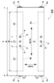
- the bolts 5 arranged at five locations in the center (point A), both ends (point C), and between the center and both ends (point B) of the cooling plate 9 cool the bind bar 4. It is a bottom view of the power supply device fixed to the plate 9.
- the difference ( ⁇ 1) in the amount of expansion and contraction due to the temperature change of the point B is It is 1/2 of the difference ( ⁇ 2) in the amount of expansion and contraction. Therefore, the bolt 5 at point B has little difference (.DELTA.1) in the amount of expansion or contraction due to temperature change between the bind bar 4 and the cooling plate 9, and loosening due to relative displacement between the bind bar 4 and the cooling plate 9 is prevented. Ru. Therefore, the power supply apparatus in which the fixing area 21 between the bind bar 4 and the cooling plate 9 is located between the points B disposed on both sides of the point A fixes the bind bar and the cooling plate with bolts to both ends (point C). Compared with the power supply unit, it has the feature of being able to prevent the loosening of the bolt.
- the power supply unit that fixes the bind bar to the cooling plate with a thick bolt has a coolant passage provided in the cooling plate because the bolt is bulky and the outer shape is enlarged and the thick bolt is screwed or penetrated into the cooling plate. As it narrows, the entire cooling plate can not be cooled uniformly.
- the power supply device that fixes the bind bar to the cooling plate with a thin bolt can prevent the bolt from becoming bulky and can reduce the outer diameter, and by narrowing the bolt, the refrigerant passage provided in the cooling plate becomes narrow. Can be realized to realize the feature that the entire cooling plate can be uniformly cooled.
- the bind bar 4 is made of iron or iron alloy
- the cooling plate 9 is made of aluminum or aluminum alloy. Further, the cooling plate 9 preferably has a total length (R) of 30 cm or more.
- the bind bar 4 has a bent portion 4 b fixed to the surface of the cooling plate 9, and fixes the bind bar 4 to the cooling plate 9 via a bolt 5 penetrating the bent portion 4 b. It may be
- the power supply device may be configured to dispose the bent portion 4 b on the outer surface of the cooling plate 9 and to fix the bent portion 4 b to the outer surface of the cooling plate 9.
- the power supply device may be configured such that the bent portion 4 b is disposed between the cooling plate 9 and the battery stack 2 and the bent portion 4 b is fixed to the surface of the cooling plate 9 facing the battery stack 2.
- the bolt 5 may be screwed into a female screw hole 9 a provided in the cooling plate 9 to be fixed.
- the nut 6 may be screwed into the bolt 5 and the cooling plate 9 may be sandwiched between the bolt 5 and the nut 6 to fix the bind bar 4 to the cooling plate 9.
- the cooling plate 9 may have flange portions 9Y extending in the longitudinal direction on both sides, and the battery stack 2 may be fitted inside the flange portions 9Y.
- the power supply device may be configured to dispose the heat conduction sheet 32 between the battery stack 2 and the cooling plate 9.
- each element constituting the present invention may be configured such that a plurality of elements are constituted by the same member and one member is used in common as a plurality of elements, or conversely, the function of one member is realized by a plurality of members It can be shared and realized.
- the contents described in some examples and embodiments may be applicable to other examples and embodiments.
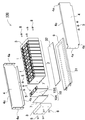
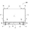
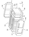
- a power supply device 100 shown in FIGS. 1 to 4 includes a battery stack 2 in which a plurality of battery cells 1 are stacked, and a pair of end plates 3 disposed at both ends in the stacking direction of the battery stack 2.
- a bind bar 4 connecting both end portions to the end plate 3 to restrain the plurality of battery cells 1 in the stacking direction, and a cooling plate 9 disposed in a thermally coupled state on the surface of the battery stack 2 Prepare.
- the battery cell 1 is a rectangular battery whose width is wider than the thickness, in other words, thinner than the width, and is stacked in the thickness direction to form a battery stack 2.
- the battery cell 1 is a non-aqueous electrolytic solution battery in which the battery case 10 is a metal case.
- the battery cell 1 which is a non-aqueous electrolyte solution battery is a lithium ion secondary battery.
- the battery cell can also be a secondary battery such as a nickel hydrogen battery or a nickel cadmium battery.
- the battery cell 1 in the figure is a battery in which both wide surfaces are square, and is stacked to face each other to form a battery stack 2.
- an electrode body (not shown) is accommodated in a metal battery case 10 having a rectangular outer shape and filled with an electrolytic solution.
- the battery case 10 formed of a metal case can be manufactured of aluminum or an aluminum alloy.
- the battery case 10 includes an outer can 10A in which a metal plate is pressed in a cylindrical shape closing the bottom, and a sealing plate 10B airtightly closing an opening of the outer can 10A.
- the sealing plate 10B is a flat metal plate, and the outer shape thereof is the shape of the opening of the outer can 10A.
- the sealing plate 10B is fixed by laser welding to the outer peripheral edge of the outer can 10A to airtightly close the opening of the outer can 10A.
- the sealing plate 10B fixed to the outer can 10A fixes the positive and negative electrode terminals 13 at both ends, and further, a gas discharge port 12 is provided between the positive and negative electrode terminals 13.
- a discharge valve 11 which opens at a predetermined internal pressure is provided inside the gas discharge port 12.
- the battery stacks 2 shown in FIGS. 1 and 2 are formed by laminating the plurality of battery cells 1 in a posture in which the surfaces provided with the discharge valves 11 are substantially on the same surface, and the discharge valves 11 of the respective battery cells 1 are identical. It is arranged on the plane. In the illustrated battery stack 2, the plurality of battery cells 1 are stacked in a posture in which the sealing plate 10 ⁇ / b> B provided with the discharge valve 11 is an upper surface.
- a plurality of battery cells 1 stacked on one another are connected in series and / or in parallel to one another by connecting positive and negative electrode terminals 13.
- the power supply device 100 connects the positive and negative electrode terminals 13 of adjacent battery cells 1 in series and / or in parallel with each other via a bus bar (not shown).
- a power supply device in which adjacent battery cells are connected in series can increase the output voltage to increase the output, and can connect adjacent battery cells in parallel to increase the charge / discharge current.
- Battery stack 2 In a battery stack 2 shown in FIG. 2, a plurality of battery cells 1 are stacked on one another via a spacer 7, and these battery cells 1 are connected in series.
- the battery stack 2 of FIG. 1 arranges the battery cells 1 adjacent to each other in the opposite direction, connects the adjacent electrode terminals 13 on both sides with a bus bar, and serially connects the two adjacent battery cells 1 It connects, and all the battery cells 1 are connected in series.
- the present invention does not specify the number of battery cells constituting the battery stack and the connection state thereof.
- the spacers 7 are sandwiched between the battery cells 1 stacked, and the adjacent battery cells 1 are stacked in an insulating state.
- the spacer 7 is an insulating plate formed of plastic in a plate shape.
- the spacer 7, which is formed of a plastic having a low thermal conductivity, has an effect of being able to effectively prevent the thermal runaway of the adjacent battery cells 1.
- the spacer 7 can be stacked so that the adjacent battery cells 1 are not misaligned as a shape in which the battery cells 1 are fitted and disposed at a predetermined position.
- the outer can can be made of metal such as aluminum.
- a spacer is formed by insulating battery cells adjacent to each other by a method such as forming an outer can of a battery cell with an insulating material, or coating the outer periphery of an outer can of a battery cell with an insulating sheet or insulating paint. Because it is unnecessary.
- a battery stack in which no spacer is interposed between battery cells is a system in which direct cooling is performed using a refrigerant or the like without adopting an air-cooling type that cools the battery cells by forcibly blowing cooling air between the battery cells. Can be used to cool the battery cell.
- End plate 3 The end plate 3 is connected to the bind bar 4 and arranges the battery stack 2 on both end faces to hold the battery cell 1 in the stacking direction.
- the end plate 3 is fixed to the bind bar 4 to fix each battery cell 1 of the battery stack 2.
- the outer shape of the end plate 3 is almost equal to or slightly larger than the outer shape of the battery cell 1, and the bind bar 4 is fixed to the outer peripheral surface of both sides to move the cell stack 2 even during vibration / impact Is a square plate having a strength to suppress
- the end plate 3 is entirely made of metal such as aluminum or aluminum alloy.
- the end plate may have a structure in which a metal plate is laminated on plastic, or alternatively, the whole may be a fiber reinforced resin molded plate in which reinforcing fibers are embedded.
- the end plate 3 is in close contact with the surface of the battery cell 1 directly or via a spacer to fix the battery cell 1.
- the power supply device 100 arranges the end plates 3 at both ends of the battery stack 2 in the assembly process, and press the end plates 3 at both ends with a press (not shown) to insert the bind bar 4. After the end plate 3 is fixed to the bind bar 4, the pressing state of the press is released.
- the cooling plate 9 cools the battery cell 1 with a coolant circulating inside.
- the cooling plate 9 is made of a metal plate such as aluminum or an aluminum alloy excellent in heat conduction characteristics.
- the cooling plate 9 is provided with a circulation path 31 for the cooling fluid inside.
- the circulation path 31 is connected to the cooling mechanism 30 to cool the cooling plate 9.
- the cooling plate 9 is disposed in a thermally coupled state on the bottom surface of the battery stack 2.
- the cooling plate 9 can also be disposed on the side surface of the battery stack 2.
- the power supply device 100 of the figure is configured to cool all the battery cells 1 as a rectangular metal plate having an outer shape of the cooling plate 9 equal to or slightly larger than the bottom shape of the battery stack 2.
- a metal pipe is inserted into the inside of a metal plate to provide a cavity, or a cavity is provided therein, and a coolant circulation passage 31 is provided inside.
- FIG. 3 and 5 are schematic cross-sectional views of the power supply devices 100, 200.
- the heat transfer sheet 32 is a sheet having flexibility and cushioning properties and excellent heat transfer characteristics.
- the heat conductive sheet 32 is sandwiched between the battery stack 2 and the cooling plate 9, and one surface is in close contact with the surface of the battery stack 2 and the other surface is in close contact with the surface of the cooling plate 9.
- the battery stack 2 and the cooling plate 9 are disposed in an ideal thermal coupling state.
- the cooling plate 9 is fixed in close contact with the surface of the battery stack 2 via the bind bar 4.
- the power supply device 100 of FIG. 1 and FIG. 2 bends both ends of the bind bar 4 inward to provide a fixing piece 4a, and fixes the fixing piece 4a to the surface of the end plate 3 via a fixing screw 8. ing.
- the present invention does not specify a structure for fixing the bind bar 4 to the end plate 3, all other fixing structures capable of firmly fixing both ends of the bind bar 4 to the end plate 3 can be used.
- the bind bar 4 shown in the figure is provided at the upper end with an upper bent piece 4c which is bent inward.
- the upper bent pieces 4c are disposed on the upper surfaces on both sides of the battery stack 2, and the terminal surfaces which are the upper surfaces of the plurality of stacked battery cells 1 are disposed on the same plane.
- the cooling plate 9 is fixed to the bind bar 4 and fixed to the battery stack 2 in a thermally coupled state.
- the bind bar 4 shown in the schematic cross sectional views of FIGS. 3 and 5 is provided with a bent portion 4 b fixed to the surface of the cooling plate 9.
- the bent portion 4 b is provided by bending the lower edge of the bind bar 4 inward.
- the bind bar 4 is fixed to the cooling plate 9 via a bolt 5 penetrating the bent portion 4b.
- the bent portion 4 b of the bind bar 4 is disposed on the outer surface of the cooling plate 9, and the bent portion 4 b is fixed to the outer surface of the cooling plate 9.
- the power supply device 100 fixes the bind bar 4 to the cooling plate 9 by screwing a bolt 5 penetrating the bent portion 4 b into a female screw hole 9 a provided on the bottom surface of the cooling plate 9.
- the bent portion 4 b of the bind bar 4 is disposed between the battery stack 2 and the cooling plate 9, and the bent portion 4 b is fixed to the surface of the cooling plate 9 facing the battery stack 2. doing.
- a nut 6 is screwed into a bolt 5 penetrating the bent portion 4b and the cooling plate 9, and the bind bar 4 is held by sandwiching the bent portion 4b and the cooling plate 9 with the bolt 5 and the nut 6. It is fixed to the cooling plate 9.
- the cooling plate 9 is provided with a through hole 9 b through which the bolt 5 is inserted.
- the bolt 5 may be caulked or welded to the bind bar 4.
- the bind bar 4 fixes both ends to the end plate 3 to restrain the battery cell 1 of the battery stack 2 in the stacking direction.
- the bind bar 4 is subjected to a strong tensile force by a load from the battery stack 2 at the time of vibration and impact.
- the bind bar 4 is made of high-tensile steel or stainless steel.
- the cooling plate 9 is required to have excellent heat transfer characteristics, and the bind bar 4 is required to have a property to withstand a strong tensile force, so that the cooling plate 9 and the bind bar 4 are made of different metals.
- the cooling plate 9 and the bind bar 4 of dissimilar metals have different amounts of expansion and contraction with respect to temperature change, and for example, the coefficient of thermal expansion of aluminum is about twice that of steel. Therefore, the cooling plate 9 made of aluminum has twice as much expansion and contraction amount with respect to a temperature change as compared with the bind bar 4 of high tensile steel.
- a relative shift occurs between the dissimilar metals due to temperature change. Deviations between dissimilar metals due to temperature changes occur at the junction of the bind bar 4 and the cooling plate 9.
- the bind bar 4 of the dissimilar metal and the cooling plate 9 move relative to each other due to the temperature change, which causes the bolt 5 to be loosened.
- the power supply device is used in an extremely wide pressing range, the relative movement with respect to the temperature change is large, which causes the bolt 5 to be loosened.
- FIG. 4 and 6 are bottom views of the power supply devices 100 and 200 for preventing the bolt 5 from loosening due to temperature change.
- 4 is a bottom view of the power supply apparatus 100 of FIG. 3
- FIG. 6 is a bottom view of the power supply apparatus 200 of FIG.
- the power supply devices 100 and 200 shown in these figures do not fix the end of the bent portion 4b of the bind bar 4 to the cooling plate 9 with a bolt.
- the bent portion 4 b is fixed to the cooling plate 9 via a plurality of bolts 5 in order to firmly fix it to the cooling plate 9.
- the structure for fixing the bind bar 4 to the cooling plate 9 with a plurality of bolts 5 can firmly fix the bind bar 4 to the cooling plate 9 with the thin bolts 5.
- the bind bar 4 can be fixed to the cooling plate 9 with one thick and strong bolt 5, the thick bolt 5 is large and bulky, so that the outer shape of the power supply device becomes large. Further, when the thick bolt 5 is screwed into or penetrated through the cooling plate 9, the volume of the circulation path 31 provided inside the cooling plate 9 is limited, which causes a problem that the whole can not be efficiently cooled. In order to prevent this harmful effect, the bind bar 4 is fixed to the cooling plate 9 by a plurality of bolts 5.
- the non-fixed area 22 where the bind bar 4 is not fixed by the bolt 5 is provided at the end of the bind bar 4 as 70% or less of the total length (T) of the bind bar 4.
- the fixed area 21 is provided at the center of the bent portion 4b, and the non-fixed area 22 having the same length is provided at both ends.
- the power supply devices 100 and 200 are characterized in that the bind bar 4 can be securely fixed to the cooling plate 9 in an ideal state. However, the fixed area does not necessarily have to be disposed at the center of the fold.
- the fixed area 21 with respect to the entire length (T) of the bind bar 4 can be reduced in length (L) to reduce loosening of the bolt 5 due to temperature change. Further, the fixing area 21 can be made longer to fix the bind bar 4 to the cooling plate 9 more reliably. Furthermore, since the loosening of the bolt 5 due to the temperature change also changes with the total length (R) of the cooling plate 9, that is, the total length (T) of the bind bar 4, the length of the fixing area 21 with respect to the total length (T) of the bind bar 4 (L) is set to an optimal value in consideration of the total length (T) of the bind bar 4 as well.
- the power supply devices 100 and 200 set the length (L) of the fixed area 21 to 70% or less of the total length (T) of the bind bar 4 or the total length (R) of the cooling plate 9.
- the length (L) of the fixing area 21 with respect to the total length (T) of the bind bar 4 is the bolt 5 loosening due to temperature change and the bind bar 4 fixed to the cooling plate 9
- the strength it is limited to, for example, 60% or less, preferably 50% or less, and more preferably 40% or less.
- the power supply devices 100 and 200 of FIGS. 4 and 6 three bolts 5 are arranged side by side in the fixing area 21 provided at the center of the bent portion 4 b of the bind bar 4 and the fixing area fixing the bolts 5.
- the length 21 (L) is 20% of the total length (M) of the bent portion 4b of the bind bar 4, and 80% non-fixed regions 22 of the total length (M) of the bent portion 4b are provided at both ends. .
- the power supply device 100, 200 has a short length (L) of the fixed area 21, it is characterized in that the loosening of the bolt 5 can be reliably prevented even when used for a long time in an environment with a significant temperature change. is there.
- the above power supply device arranges three bolts 5 in the fixed area 21 and fixes the bind bar 4 to the cooling plate 9, but arranges two or four or more bolts 5 in the fixed area 21.
- the bind bar 4 can also be fixed to the cooling plate 9.
- the power supply devices 300 and 400 shown in the schematic cross sectional views of FIGS. 7 and 8 are provided with flange portions 9Y extending along the longitudinal direction on both sides of the cooling plate 9, and the battery stack 2 is provided inside the flange portions 9Y on both sides. Are placed in the fitted state.
- the main body 9X is in close thermal contact with the bottom of the battery stack 2 and the inner surface of the flange 9Y is in close thermal contact with both sides of the battery stack 2.
- the battery stack 2 is disposed inside the flanges 9Y on both sides, and the position in the width direction (X-axis direction in FIGS. 4 and 6) between the cooling plate 9 and the battery stack 2. Stop the gap. Therefore, the connection rigidity of both can be enhanced in the X-axis direction.
- the power supply devices 300, 400 prevent positional deviation of the battery stack 2 and the cooling plate 9 in the longitudinal direction (Y-axis direction in FIGS.
- the power supply devices 300 and 400 prevent positional deviation in the X-axis direction with the flange portion 9Y, so only the positional deviation in the Y-axis direction is prevented with the bolt 5 to ensure the battery stack 2 and the cooling plate 9 reliably. It can be fixed not to be misaligned. Therefore, the power supply devices 300 and 400 of this structure shorten the length (L) of the fixing area 21 and effectively prevent the loosening of the bearing surface of the bolt 5 while the cooling plate 9 and the battery stack 2 are There is a feature that can be firmly connected in an ideal state without misalignment.
- the cooling plate 9 described above can be formed by die-casting or extruding aluminum to provide the flange portion 9Y in an integral structure. However, it is also possible to fix the flange portion 9Y as a separate member to the main body portion 9X.
- the power supply device of the above-described embodiment is configured to include the cooling plate 9 that cools the battery cell 1 with the coolant circulating in the inside, in the present invention, the cooling plate does not necessarily cool the inside of the plate.
- the configuration may not be such that the liquid circulates.
- the cooling plate may be a heat conducting plate formed by molding a highly heat conductive material such as aluminum. In this configuration, the battery cells can be cooled by utilizing the thermal conductivity of the plate, and since it is not necessary to circulate the coolant or the like, the configuration can be simplified. These may be selected according to the required cooling performance.
- the power supply devices 100 and 300 of FIGS. 1 to 4 and FIG. 7 are assembled in the following steps.
- a predetermined number of battery cells 1 are stacked in the thickness direction of the battery cells 1 with the spacers 7 interposed therebetween to form a battery stack 2.
- the end plates 3 are disposed at both ends of the battery stack 2, and the pair of end plates 3 are pressed from both sides by a press (not shown) and held.
- the cooling plate 9 is disposed on the bottom of the battery stack 2 via the heat conductive sheet 32.
- the battery stack 2 is fitted between the flange portions 9 ⁇ / b> Y provided on both sides of the cooling plate 9.
- the facing electrode terminals 13 of the battery cells 1 adjacent to each other are connected by a bus bar (not shown).
- the bus bar is fixed to the electrode terminal 13 to connect the battery cells 1 in series or in parallel to the series.
- the bus bar is welded or screwed to the electrode terminal 13 and fixed to the electrode terminal 13.
- the power supply devices 200 and 400 of FIG. 5, FIG. 6, and FIG. 8 are assembled in the following steps.
- Bind bars 4 are connected and fixed to the pair of end plates 3 in a compressed state with the end plate 3 of the battery stack 2.
- fixing pieces 4 a provided at both ends are fixed to the outer surface of the end plate 3 via fixing screws 8.
- the battery stack 2 is held via the pair of end plates 3 held at predetermined intervals by the bind bar 4.
- the bent portion 4 b of the bind bar 4 is fixed to the cooling plate 9.
- the bent portion 4 b is disposed between the cooling plate 9 and the battery stack 2, and is fixed to the surface of the cooling plate 9 facing the battery stack 2.
- the bolt 5 passing through the bent portion 4 b is inserted into the through hole 9 b of the cooling plate 9, and the nut 6 is screwed into the bolt 5 to clamp the cooling plate 9 with the bolt 5 and the nut 6. It is fixed.
- the heat conduction sheet 32 is interposed between the battery stack 2 and the cooling plate 9.
- the battery stack 2 is fitted between the flanges 9 Y provided on both sides of the cooling plate 9, and the flanges 9 Y are disposed on the outer surface of the bind bar 4.
- the facing electrode terminals 13 of the battery cells 1 adjacent to each other are connected by a bus bar (not shown).
- the bus bar is fixed to the electrode terminal 13 to connect the battery cells 1 in series or in parallel to the series.
- the bus bar is welded or screwed to the electrode terminal 13 and fixed to the electrode terminal 13.
- the above power supply device is most suitable for a power supply device for a vehicle that supplies electric power to a motor for traveling an electric vehicle.
- a power supply device for a vehicle that supplies electric power to a motor for traveling an electric vehicle.
- an electric vehicle carrying a power supply device an electric vehicle such as a hybrid car or plug-in hybrid car traveling with both an engine and a motor or an electric car traveling only with a motor can be used. Be done.
- FIG. 9 shows an example in which the power supply device is mounted on a hybrid vehicle traveling with both an engine and a motor.
- the vehicle HV equipped with the power supply device shown in this figure includes a vehicle body 90, an engine 96 for traveling the vehicle body 90, a motor 93 for traveling, a power supply device 100 for supplying power to the motor 93, and a power supply device 100.
- a generator 94 for charging the battery, and a wheel 97 driven by the motor 93 and the engine 96 to travel the vehicle body 90 are provided.
- the power supply device 100 is connected to the motor 93 and the generator 94 via a DC / AC inverter 95.
- the vehicle HV travels with both the motor 93 and the engine 96 while charging and discharging the battery of the power supply device 100.
- the motor 93 is driven in a region where the engine efficiency is low, for example, at the time of acceleration or low speed traveling to drive the vehicle.
- the motor 93 is supplied with power from the power supply device 100 and is driven.
- the generator 94 is driven by the engine 96 or driven by regenerative braking when the vehicle is braked to charge the battery of the power supply device 100.
- FIG. 10 shows an example in which the power supply device is mounted on an electric vehicle traveling only by a motor.
- the vehicle EV mounted with the power supply device shown in this figure includes a vehicle body 90, a traveling motor 93 for traveling the vehicle body 90, a power supply device 100 for supplying power to the motor 93, and a battery of the power supply device 100. And a wheel 97 driven by a motor 93 to travel the vehicle body 90.
- the motor 93 is supplied with power from the power supply device 100 and is driven.
- the generator 94 is driven by energy when regenerative braking the vehicle EV, and charges the battery of the power supply device 100.
- the present invention does not specify the use of the power supply device as a power supply device mounted on an electric vehicle, and can be used as a power supply device for a storage device for storing natural energy such as solar power generation and wind power generation. It can be used for all applications that store large electric power, such as a power supply device for a power storage device that stores electric power.
- a power supply for home use or factory use a power supply system that charges with sunlight or late-night power and discharges it when necessary, or a streetlight power supply that charges sunlight during the day and discharges it at night, It can also be used as a backup power supply for driving traffic signals.
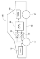
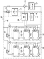
- FIG. Note that, in the usage example as a power storage device shown in FIG. 11, in order to obtain desired power, a large number of high-power, high-power devices are obtained by connecting many of the above-described power supply devices in series or in parallel and adding necessary control circuits. Description will be made as an example in which power storage device 80 is constructed.
- a power storage device 80 shown in FIG. 11 configures a power supply unit 82 by connecting a plurality of power supply devices 100 in a unit form.
- a plurality of battery cells are connected in series and / or in parallel.
- Each power supply device 100 is controlled by a power supply controller 84.
- the power storage device 80 drives the load LD after charging the power supply unit 82 with the charging power supply CP. Therefore, power storage device 80 has a charge mode and a discharge mode.
- the load LD and the charging power supply CP are connected to the storage device 80 through the discharge switch DS and the charging switch CS, respectively.
- the ON / OFF of the discharge switch DS and the charge switch CS is switched by the power controller 84 of the power storage device 80.
- the power supply controller 84 switches the charge switch CS to ON and the discharge switch DS to OFF to allow charging of the storage battery 80 from the charging power supply CP. Also, when the charging is completed and the battery is fully charged, or when the capacity more than a predetermined value is charged, the power supply controller 84 turns off the charging switch CS and turns on the discharging switch DS to discharge in response to a request from the load LD. It switches to the mode and permits discharge from the storage device 80 to the load LD. In addition, if necessary, the charge switch CS can be turned on and the discharge switch DS can be turned on to simultaneously perform the power supply of the load LD and the charging of the power storage device 80.
- the load LD driven by the storage device 80 is connected to the storage device 80 via the discharge switch DS.
- the power supply controller 84 switches the discharge switch DS to ON, connects it to the load LD, and drives the load LD with the power from the storage device 80.
- the discharge switch DS can use a switching element such as an FET.
- the ON / OFF of the discharge switch DS is controlled by the power supply controller 84 of the power storage device 80.
- the power supply controller 84 also includes a communication interface for communicating with an external device. In the example of FIG. 11, the host device HT is connected according to the existing communication protocol such as UART or RS-232C. Also, if necessary, a user interface may be provided for the user to operate the power supply system.
- Each power supply device 100 includes a signal terminal and a power terminal.
- the signal terminals include an input / output terminal DI, an abnormal output terminal DA, and a connection terminal DO.
- the input / output terminal DI is a terminal for inputting / outputting a signal from another power supply apparatus 100 or a power supply controller 84
- the connection terminal DO is a terminal for inputting / outputting a signal to / from the other power supply apparatus 100.
- the abnormality output terminal DA is a terminal for outputting the abnormality of the power supply device 100 to the outside.
- the power supply terminal is a terminal for connecting the power supply devices 100 in series and in parallel.
- the power supply units 82 are connected to the output line OL via the parallel connection switch 85 and connected in parallel to each other.
- the power supply device according to the present invention, a vehicle including the same, and a power storage device are suitably used as a power supply device for a plug-in hybrid electric vehicle, a hybrid electric vehicle, an electric vehicle or the like capable of switching between the EV travel mode and the HEV travel mode. it can.
- a backup power supply that can be mounted in a rack of a computer server, a backup power supply for a wireless base station such as a mobile phone, a storage power for household use and a factory, a power supply for street lights, etc. It can also be suitably used for backup power sources such as traffic lights.
- Cooling plate 9 Main body portion 9Y: Flange portion 9a: female screw hole 9b: through hole 10: battery case 10A: outer package can DESCRIPTION OF SYMBOLS 10B ... Sealing plate, 11 ... Discharge valve, 12 ... Gas discharge port, 13 ... Electrode terminal, 21 ... Fixed area, 22 ... Non-fixed area, 30 ... Cooling mechanism, 31 ... Circulation path, 32 ...
- Heat conduction sheet 80 ... Storage device, 82: power supply unit, 84: power supply controller, 85: parallel connection switch, 90: vehicle body, 93: motor, 94: generator, 95: DC / AC inverter, 96: engine, 97: wheel, 101: 101 Electricity Cell 102 102 battery stack 103 end plate 104 bind bar 104b bent portion 109 cooling plate EV: vehicle HV: vehicle load: CP charge power source: DS discharge switch , CS ... charge switch, OL ... output line, HT ... host device, DI ... input / output terminal, DA ... abnormal output terminal, DO ... connection terminal
Landscapes
- Chemical & Material Sciences (AREA)
- Chemical Kinetics & Catalysis (AREA)
- Electrochemistry (AREA)
- General Chemical & Material Sciences (AREA)
- Engineering & Computer Science (AREA)
- Manufacturing & Machinery (AREA)
- Inorganic Chemistry (AREA)
- Aviation & Aerospace Engineering (AREA)
- Secondary Cells (AREA)
- Battery Mounting, Suspending (AREA)
Abstract
Afin de maintenir une plaque de refroidissement et un empilement de batterie dans un état lié thermiquement idéal par prévention du desserrage d'un boulon sur une longue période tout en fixant la plaque de refroidissement à l'empilement de batterie par l'intermédiaire du boulon, l'invention porte sur un dispositif d'alimentation électrique dans lequel les deux extrémités d'une barre de liaison (4) sont accouplées à une paire de plaques d'extrémité disposées aux deux extrémités dans la direction d'empilement d'un empilement de batterie formé par empilement d'une pluralité d'éléments de batterie, ce qui permet de fixer la pluralité d'éléments de batterie dans la direction d'empilement, une plaque de refroidissement (9) formée d'un type de métal différent de celui de la barre de liaison (4) est disposée dans un état couplé thermiquement sur la surface de l'empilement de batterie, et la plaque de refroidissement (9) est fixée à l'empilement de batterie par l'intermédiaire d'une pluralité de boulons (5) disposés dans la direction longitudinale de l'empilement de batterie. Dans le dispositif d'alimentation électrique, la longueur (L) d'une région fixée (21) dans laquelle la barre de liaison (4) est fixée à la plaque de refroidissement (9) par l'intermédiaire de la pluralité de boulons (5) est réglée à 70 % ou moins de la longueur totale (T) de la barre de liaison (4), et une région non fixée (22) qui n'est pas fixée à la plaque de refroidissement (9) par l'intermédiaire du boulon (5) est ménagée à une extrémité de la barre de liaison (4).
Priority Applications (4)
| Application Number | Priority Date | Filing Date | Title |
|---|---|---|---|
| JP2019567876A JP7208170B2 (ja) | 2018-01-25 | 2018-11-26 | 電源装置及び電源装置を備える車両並びに蓄電装置 |
| EP18902037.3A EP3745525B1 (fr) | 2018-01-25 | 2018-11-26 | Dispositif d'alimentation électrique, véhicule équipé d'un dispositif d'alimentation électrique, et dispositif de stockage d'énergie |
| CN201880087487.8A CN111630706B (zh) | 2018-01-25 | 2018-11-26 | 电源装置以及具备电源装置的车辆和蓄电装置 |
| US16/960,381 US20200358127A1 (en) | 2018-01-25 | 2018-11-26 | Power supply device, vehicle provided with power supply device, and power storage device |
Applications Claiming Priority (2)
| Application Number | Priority Date | Filing Date | Title |
|---|---|---|---|
| JP2018010948 | 2018-01-25 | ||
| JP2018-010948 | 2018-01-25 |
Publications (1)
| Publication Number | Publication Date |
|---|---|
| WO2019146238A1 true WO2019146238A1 (fr) | 2019-08-01 |
Family
ID=67394782
Family Applications (1)
| Application Number | Title | Priority Date | Filing Date |
|---|---|---|---|
| PCT/JP2018/043384 WO2019146238A1 (fr) | 2018-01-25 | 2018-11-26 | Dispositif d'alimentation électrique, véhicule équipé d'un dispositif d'alimentation électrique, et dispositif de stockage d'énergie |
Country Status (5)
| Country | Link |
|---|---|
| US (1) | US20200358127A1 (fr) |
| EP (1) | EP3745525B1 (fr) |
| JP (1) | JP7208170B2 (fr) |
| CN (1) | CN111630706B (fr) |
| WO (1) | WO2019146238A1 (fr) |
Cited By (5)
| Publication number | Priority date | Publication date | Assignee | Title |
|---|---|---|---|---|
| CN113131582A (zh) * | 2021-04-21 | 2021-07-16 | 和鸿电气股份有限公司 | 一种方便移动电源内部安装的电源箱 |
| JP2022524767A (ja) * | 2019-10-10 | 2022-05-10 | エルジー エナジー ソリューション リミテッド | 電池モジュールおよびこれを含む電池パック |
| JP2023512819A (ja) * | 2020-06-02 | 2023-03-29 | エルジー エナジー ソリューション リミテッド | パックケースに冷媒循環路を備えた電池パック |
| EP4033588A4 (fr) * | 2019-11-22 | 2023-10-18 | Lg Energy Solution, Ltd. | Module de batterie et bloc-batterie comprenant ledit module de batterie |
| JP7460483B2 (ja) | 2020-08-27 | 2024-04-02 | 本田技研工業株式会社 | 発熱体冷却機構 |
Families Citing this family (4)
| Publication number | Priority date | Publication date | Assignee | Title |
|---|---|---|---|---|
| WO2019245028A1 (fr) * | 2018-06-22 | 2019-12-26 | 株式会社Gsユアサ | Dispositif de stockage d'énergie |
| WO2020110447A1 (fr) * | 2018-11-28 | 2020-06-04 | 三洋電機株式会社 | Module de batterie |
| CN114256549B (zh) * | 2021-12-20 | 2023-04-14 | 厦门海辰储能科技股份有限公司 | 电池模组和储能设备 |
| EP4239767B1 (fr) * | 2022-03-02 | 2024-05-22 | Northvolt AB | Système de batterie |
Citations (4)
| Publication number | Priority date | Publication date | Assignee | Title |
|---|---|---|---|---|
| WO2012133708A1 (fr) * | 2011-03-31 | 2012-10-04 | 三洋電機株式会社 | Dispositif de source d'alimentation et véhicule comportant un dispositif de source d'alimentation |
| JP2015520924A (ja) * | 2012-05-16 | 2015-07-23 | ローベルト ボツシユ ゲゼルシヤフト ミツト ベシユレンクテル ハフツングRobert Bosch Gmbh | バッテリアッセンブリ |
| JP2015220117A (ja) | 2014-05-19 | 2015-12-07 | 本田技研工業株式会社 | 蓄電モジュール |
| WO2016174855A1 (fr) * | 2015-04-28 | 2016-11-03 | 三洋電機株式会社 | Dispositif source d'alimentation électrique et véhicule équipé de ce dernier |
Family Cites Families (18)
| Publication number | Priority date | Publication date | Assignee | Title |
|---|---|---|---|---|
| US6162559A (en) * | 1998-09-21 | 2000-12-19 | Douglas Battery Manufacturing Company | Compressed battery system for motive power applications |
| JP5442268B2 (ja) * | 2009-01-28 | 2014-03-12 | 三洋電機株式会社 | バッテリシステム |
| JP5470604B2 (ja) * | 2009-10-05 | 2014-04-16 | エリーパワー株式会社 | 密閉型電池 |
| JP2011171029A (ja) * | 2010-02-17 | 2011-09-01 | Sanyo Electric Co Ltd | 電池モジュール |
| JP2012133708A (ja) * | 2010-12-24 | 2012-07-12 | Canon Inc | ファイル記録装置およびその制御方法、プログラム、記憶媒体 |
| JP5734704B2 (ja) | 2011-02-28 | 2015-06-17 | 三洋電機株式会社 | 電源装置及び電源装置を備える車両 |
| JP2012248339A (ja) * | 2011-05-25 | 2012-12-13 | Sanyo Electric Co Ltd | 電力用の電源装置及び電源装置を備える車両 |
| JP2013012441A (ja) * | 2011-06-30 | 2013-01-17 | Sanyo Electric Co Ltd | 電源装置及び電源装置を備える車両 |
| JP2013025982A (ja) * | 2011-07-20 | 2013-02-04 | Sanyo Electric Co Ltd | 電源装置及び電源装置を備える車両 |
| JP2013025983A (ja) * | 2011-07-20 | 2013-02-04 | Sanyo Electric Co Ltd | 電源装置及び電源装置を備える車両 |
| JP2015111493A (ja) * | 2012-03-28 | 2015-06-18 | 三洋電機株式会社 | 電源装置及びこれを備える車両並びに蓄電装置 |
| KR101794265B1 (ko) * | 2013-07-18 | 2017-11-07 | 삼성에스디아이 주식회사 | 보강 비드부를 포함하는 배터리 팩 |
| KR101609212B1 (ko) * | 2013-08-28 | 2016-04-05 | 주식회사 엘지화학 | 냉매 및 배기 가스의 혼합을 방지하는 구조를 포함하는 전지모듈 |
| JP6392323B2 (ja) * | 2014-03-25 | 2018-09-19 | 三洋電機株式会社 | バッテリシステム |
| EP3291358A1 (fr) * | 2016-08-31 | 2018-03-07 | Akasol GmbH | Ensemble modulaire de batterie et plaque de refroidissement a utiliser dans un ensemble modulaire de batterie |
| CN106972128B (zh) * | 2017-06-01 | 2022-12-06 | 湖南宏迅亿安新能源科技有限公司 | 一种电池模组 |
| WO2018235556A1 (fr) * | 2017-06-22 | 2018-12-27 | 三洋電機株式会社 | Dispositif d'alimentation électrique, véhicule équipé dudit dispositif d'alimentation électrique et dispositif de stockage d'électricité |
| CN107611308A (zh) * | 2017-09-23 | 2018-01-19 | 芜湖雪影实业有限公司 | 电动汽车电池安装结构 |
-
2018
- 2018-11-26 CN CN201880087487.8A patent/CN111630706B/zh active Active
- 2018-11-26 JP JP2019567876A patent/JP7208170B2/ja active Active
- 2018-11-26 WO PCT/JP2018/043384 patent/WO2019146238A1/fr active Application Filing
- 2018-11-26 EP EP18902037.3A patent/EP3745525B1/fr active Active
- 2018-11-26 US US16/960,381 patent/US20200358127A1/en not_active Abandoned
Patent Citations (4)
| Publication number | Priority date | Publication date | Assignee | Title |
|---|---|---|---|---|
| WO2012133708A1 (fr) * | 2011-03-31 | 2012-10-04 | 三洋電機株式会社 | Dispositif de source d'alimentation et véhicule comportant un dispositif de source d'alimentation |
| JP2015520924A (ja) * | 2012-05-16 | 2015-07-23 | ローベルト ボツシユ ゲゼルシヤフト ミツト ベシユレンクテル ハフツングRobert Bosch Gmbh | バッテリアッセンブリ |
| JP2015220117A (ja) | 2014-05-19 | 2015-12-07 | 本田技研工業株式会社 | 蓄電モジュール |
| WO2016174855A1 (fr) * | 2015-04-28 | 2016-11-03 | 三洋電機株式会社 | Dispositif source d'alimentation électrique et véhicule équipé de ce dernier |
Non-Patent Citations (1)
| Title |
|---|
| See also references of EP3745525A4 |
Cited By (7)
| Publication number | Priority date | Publication date | Assignee | Title |
|---|---|---|---|---|
| JP2022524767A (ja) * | 2019-10-10 | 2022-05-10 | エルジー エナジー ソリューション リミテッド | 電池モジュールおよびこれを含む電池パック |
| US11894537B2 (en) | 2019-10-10 | 2024-02-06 | Lg Energy Solution, Ltd. | Battery module and battery pack including the same |
| EP4033588A4 (fr) * | 2019-11-22 | 2023-10-18 | Lg Energy Solution, Ltd. | Module de batterie et bloc-batterie comprenant ledit module de batterie |
| JP2023512819A (ja) * | 2020-06-02 | 2023-03-29 | エルジー エナジー ソリューション リミテッド | パックケースに冷媒循環路を備えた電池パック |
| JP7362051B2 (ja) | 2020-06-02 | 2023-10-17 | エルジー エナジー ソリューション リミテッド | パックケースに冷媒循環路を備えた電池パック |
| JP7460483B2 (ja) | 2020-08-27 | 2024-04-02 | 本田技研工業株式会社 | 発熱体冷却機構 |
| CN113131582A (zh) * | 2021-04-21 | 2021-07-16 | 和鸿电气股份有限公司 | 一种方便移动电源内部安装的电源箱 |
Also Published As
| Publication number | Publication date |
|---|---|
| JPWO2019146238A1 (ja) | 2021-01-07 |
| EP3745525A4 (fr) | 2021-03-10 |
| CN111630706A (zh) | 2020-09-04 |
| EP3745525B1 (fr) | 2024-01-03 |
| EP3745525A1 (fr) | 2020-12-02 |
| US20200358127A1 (en) | 2020-11-12 |
| JP7208170B2 (ja) | 2023-01-18 |
| CN111630706B (zh) | 2024-03-05 |
Similar Documents
| Publication | Publication Date | Title |
|---|---|---|
| WO2019146238A1 (fr) | Dispositif d'alimentation électrique, véhicule équipé d'un dispositif d'alimentation électrique, et dispositif de stockage d'énergie | |
| JP7348180B2 (ja) | バッテリシステムとバッテリシステムを備える電動車両及び蓄電装置 | |
| JP7284710B2 (ja) | 電源装置及び電源装置を備える車両並びに蓄電装置 | |
| JP5734704B2 (ja) | 電源装置及び電源装置を備える車両 | |
| JP6073583B2 (ja) | 電源装置及びこの電源装置を備える車両並びに蓄電装置 | |
| WO2014034057A1 (fr) | Système de batterie, véhicule électrique équipé de ce système de batterie et dispositif de stockage d'électricité | |
| JP5985255B2 (ja) | 電源装置及びこの電源装置を備える車両並びに蓄電装置 | |
| WO2012133707A1 (fr) | Dispositif de source d'alimentation et véhicule comportant un dispositif de source d'alimentation | |
| WO2013084756A1 (fr) | Dispositif d'alimentation électrique, véhicule équipé dudit dispositif d'alimentation électrique, et dispositif de stockage électrique | |
| JP7260486B2 (ja) | 電源装置及び電源装置を備える車両並びに蓄電装置 | |
| JP6184959B2 (ja) | バッテリシステム及びバッテリシステムを備える車両並びに蓄電装置 | |
| JP2013125617A (ja) | 電源装置及びこれを備える車両並びに蓄電装置 | |
| JPWO2018235556A1 (ja) | 電源装置及びこれを備える車両並びに蓄電装置 | |
| JP2012160347A (ja) | 電源装置及び電源装置を備える車両 | |
| JP2015207341A (ja) | 電源装置及び電源装置を備える電動車両並びに蓄電装置 | |
| JP2012094456A (ja) | 電源装置 | |
| WO2012147801A1 (fr) | Dispositif d'alimentation en énergie et véhicule équipé du dispositif d'alimentation en énergie | |
| JP7276894B2 (ja) | 電源装置及びこれを備える車両並びに緩衝体 | |
| WO2021149299A1 (fr) | Dispositif d'alimentation électrique et véhicule électrique ainsi que dispositif de stockage d'énergie équipé dudit dispositif d'alimentation électrique | |
| WO2021039197A1 (fr) | Dispositif d'alimentation, véhicule électrique l'utilisant et dispositif de stockage d'énergie | |
| JP7286668B2 (ja) | バッテリシステムとバッテリシステムを備える車両及び蓄電装置 | |
| WO2021149298A1 (fr) | Dispositif d'alimentation électrique, véhicule électrique équipé d'un dispositif d'alimentation électrique, et dispositif de stockage d'énergie | |
| WO2021199534A1 (fr) | Dispositif de source d'alimentation, et véhicule et dispositif de stockage électrique chacun équipé de celui-ci | |
| WO2021199489A1 (fr) | Module de batterie, et véhicule électrique et dispositif de stockage d'énergie comprenant le module de batterie | |
| WO2020194930A1 (fr) | Dispositif d'alimentation électrique, véhicule électrique le comportant, et dispositif de stockage d'énergie |
Legal Events
| Date | Code | Title | Description |
|---|---|---|---|
| 121 | Ep: the epo has been informed by wipo that ep was designated in this application |
Ref document number: 18902037 Country of ref document: EP Kind code of ref document: A1 |
|
| WWE | Wipo information: entry into national phase |
Ref document number: 2019567876 Country of ref document: JP |
|
| NENP | Non-entry into the national phase |
Ref country code: DE |
|
| ENP | Entry into the national phase |
Ref document number: 2018902037 Country of ref document: EP Effective date: 20200825 |