WO2019146238A1 - Power supply device, vehicle provided with power supply device, and power storage device - Google Patents
Power supply device, vehicle provided with power supply device, and power storage device Download PDFInfo
- Publication number
- WO2019146238A1 WO2019146238A1 PCT/JP2018/043384 JP2018043384W WO2019146238A1 WO 2019146238 A1 WO2019146238 A1 WO 2019146238A1 JP 2018043384 W JP2018043384 W JP 2018043384W WO 2019146238 A1 WO2019146238 A1 WO 2019146238A1
- Authority
- WO
- WIPO (PCT)
- Prior art keywords
- power supply
- cooling plate
- supply device
- battery stack
- battery
- Prior art date
Links
Images


Classifications
-
- H—ELECTRICITY
- H01—ELECTRIC ELEMENTS
- H01M—PROCESSES OR MEANS, e.g. BATTERIES, FOR THE DIRECT CONVERSION OF CHEMICAL ENERGY INTO ELECTRICAL ENERGY
- H01M10/00—Secondary cells; Manufacture thereof
- H01M10/04—Construction or manufacture in general
- H01M10/0468—Compression means for stacks of electrodes and separators
-
- H—ELECTRICITY
- H01—ELECTRIC ELEMENTS
- H01M—PROCESSES OR MEANS, e.g. BATTERIES, FOR THE DIRECT CONVERSION OF CHEMICAL ENERGY INTO ELECTRICAL ENERGY
- H01M10/00—Secondary cells; Manufacture thereof
- H01M10/60—Heating or cooling; Temperature control
- H01M10/65—Means for temperature control structurally associated with the cells
- H01M10/655—Solid structures for heat exchange or heat conduction
- H01M10/6556—Solid parts with flow channel passages or pipes for heat exchange
-
- H—ELECTRICITY
- H01—ELECTRIC ELEMENTS
- H01M—PROCESSES OR MEANS, e.g. BATTERIES, FOR THE DIRECT CONVERSION OF CHEMICAL ENERGY INTO ELECTRICAL ENERGY
- H01M10/00—Secondary cells; Manufacture thereof
- H01M10/04—Construction or manufacture in general
- H01M10/0481—Compression means other than compression means for stacks of electrodes and separators
-
- H—ELECTRICITY
- H01—ELECTRIC ELEMENTS
- H01M—PROCESSES OR MEANS, e.g. BATTERIES, FOR THE DIRECT CONVERSION OF CHEMICAL ENERGY INTO ELECTRICAL ENERGY
- H01M10/00—Secondary cells; Manufacture thereof
- H01M10/60—Heating or cooling; Temperature control
- H01M10/61—Types of temperature control
- H01M10/613—Cooling or keeping cold
-
- H—ELECTRICITY
- H01—ELECTRIC ELEMENTS
- H01M—PROCESSES OR MEANS, e.g. BATTERIES, FOR THE DIRECT CONVERSION OF CHEMICAL ENERGY INTO ELECTRICAL ENERGY
- H01M10/00—Secondary cells; Manufacture thereof
- H01M10/60—Heating or cooling; Temperature control
- H01M10/62—Heating or cooling; Temperature control specially adapted for specific applications
- H01M10/625—Vehicles
-
- H—ELECTRICITY
- H01—ELECTRIC ELEMENTS
- H01M—PROCESSES OR MEANS, e.g. BATTERIES, FOR THE DIRECT CONVERSION OF CHEMICAL ENERGY INTO ELECTRICAL ENERGY
- H01M10/00—Secondary cells; Manufacture thereof
- H01M10/60—Heating or cooling; Temperature control
- H01M10/64—Heating or cooling; Temperature control characterised by the shape of the cells
- H01M10/647—Prismatic or flat cells, e.g. pouch cells
-
- H—ELECTRICITY
- H01—ELECTRIC ELEMENTS
- H01M—PROCESSES OR MEANS, e.g. BATTERIES, FOR THE DIRECT CONVERSION OF CHEMICAL ENERGY INTO ELECTRICAL ENERGY
- H01M10/00—Secondary cells; Manufacture thereof
- H01M10/60—Heating or cooling; Temperature control
- H01M10/65—Means for temperature control structurally associated with the cells
- H01M10/653—Means for temperature control structurally associated with the cells characterised by electrically insulating or thermally conductive materials
-
- H—ELECTRICITY
- H01—ELECTRIC ELEMENTS
- H01M—PROCESSES OR MEANS, e.g. BATTERIES, FOR THE DIRECT CONVERSION OF CHEMICAL ENERGY INTO ELECTRICAL ENERGY
- H01M10/00—Secondary cells; Manufacture thereof
- H01M10/60—Heating or cooling; Temperature control
- H01M10/65—Means for temperature control structurally associated with the cells
- H01M10/655—Solid structures for heat exchange or heat conduction
- H01M10/6554—Rods or plates
-
- H—ELECTRICITY
- H01—ELECTRIC ELEMENTS
- H01M—PROCESSES OR MEANS, e.g. BATTERIES, FOR THE DIRECT CONVERSION OF CHEMICAL ENERGY INTO ELECTRICAL ENERGY
- H01M50/00—Constructional details or processes of manufacture of the non-active parts of electrochemical cells other than fuel cells, e.g. hybrid cells
- H01M50/20—Mountings; Secondary casings or frames; Racks, modules or packs; Suspension devices; Shock absorbers; Transport or carrying devices; Holders
- H01M50/204—Racks, modules or packs for multiple batteries or multiple cells
- H01M50/207—Racks, modules or packs for multiple batteries or multiple cells characterised by their shape
- H01M50/209—Racks, modules or packs for multiple batteries or multiple cells characterised by their shape adapted for prismatic or rectangular cells
-
- H—ELECTRICITY
- H01—ELECTRIC ELEMENTS
- H01M—PROCESSES OR MEANS, e.g. BATTERIES, FOR THE DIRECT CONVERSION OF CHEMICAL ENERGY INTO ELECTRICAL ENERGY
- H01M50/00—Constructional details or processes of manufacture of the non-active parts of electrochemical cells other than fuel cells, e.g. hybrid cells
- H01M50/20—Mountings; Secondary casings or frames; Racks, modules or packs; Suspension devices; Shock absorbers; Transport or carrying devices; Holders
- H01M50/218—Mountings; Secondary casings or frames; Racks, modules or packs; Suspension devices; Shock absorbers; Transport or carrying devices; Holders characterised by the material
- H01M50/22—Mountings; Secondary casings or frames; Racks, modules or packs; Suspension devices; Shock absorbers; Transport or carrying devices; Holders characterised by the material of the casings or racks
- H01M50/222—Inorganic material
- H01M50/224—Metals
-
- H—ELECTRICITY
- H01—ELECTRIC ELEMENTS
- H01M—PROCESSES OR MEANS, e.g. BATTERIES, FOR THE DIRECT CONVERSION OF CHEMICAL ENERGY INTO ELECTRICAL ENERGY
- H01M50/00—Constructional details or processes of manufacture of the non-active parts of electrochemical cells other than fuel cells, e.g. hybrid cells
- H01M50/20—Mountings; Secondary casings or frames; Racks, modules or packs; Suspension devices; Shock absorbers; Transport or carrying devices; Holders
- H01M50/249—Mountings; Secondary casings or frames; Racks, modules or packs; Suspension devices; Shock absorbers; Transport or carrying devices; Holders specially adapted for aircraft or vehicles, e.g. cars or trains
-
- H—ELECTRICITY
- H01—ELECTRIC ELEMENTS
- H01M—PROCESSES OR MEANS, e.g. BATTERIES, FOR THE DIRECT CONVERSION OF CHEMICAL ENERGY INTO ELECTRICAL ENERGY
- H01M50/00—Constructional details or processes of manufacture of the non-active parts of electrochemical cells other than fuel cells, e.g. hybrid cells
- H01M50/20—Mountings; Secondary casings or frames; Racks, modules or packs; Suspension devices; Shock absorbers; Transport or carrying devices; Holders
- H01M50/262—Mountings; Secondary casings or frames; Racks, modules or packs; Suspension devices; Shock absorbers; Transport or carrying devices; Holders with fastening means, e.g. locks
- H01M50/264—Mountings; Secondary casings or frames; Racks, modules or packs; Suspension devices; Shock absorbers; Transport or carrying devices; Holders with fastening means, e.g. locks for cells or batteries, e.g. straps, tie rods or peripheral frames
-
- Y—GENERAL TAGGING OF NEW TECHNOLOGICAL DEVELOPMENTS; GENERAL TAGGING OF CROSS-SECTIONAL TECHNOLOGIES SPANNING OVER SEVERAL SECTIONS OF THE IPC; TECHNICAL SUBJECTS COVERED BY FORMER USPC CROSS-REFERENCE ART COLLECTIONS [XRACs] AND DIGESTS
- Y02—TECHNOLOGIES OR APPLICATIONS FOR MITIGATION OR ADAPTATION AGAINST CLIMATE CHANGE
- Y02E—REDUCTION OF GREENHOUSE GAS [GHG] EMISSIONS, RELATED TO ENERGY GENERATION, TRANSMISSION OR DISTRIBUTION
- Y02E60/00—Enabling technologies; Technologies with a potential or indirect contribution to GHG emissions mitigation
- Y02E60/10—Energy storage using batteries
-
- Y—GENERAL TAGGING OF NEW TECHNOLOGICAL DEVELOPMENTS; GENERAL TAGGING OF CROSS-SECTIONAL TECHNOLOGIES SPANNING OVER SEVERAL SECTIONS OF THE IPC; TECHNICAL SUBJECTS COVERED BY FORMER USPC CROSS-REFERENCE ART COLLECTIONS [XRACs] AND DIGESTS
- Y02—TECHNOLOGIES OR APPLICATIONS FOR MITIGATION OR ADAPTATION AGAINST CLIMATE CHANGE
- Y02P—CLIMATE CHANGE MITIGATION TECHNOLOGIES IN THE PRODUCTION OR PROCESSING OF GOODS
- Y02P70/00—Climate change mitigation technologies in the production process for final industrial or consumer products
- Y02P70/50—Manufacturing or production processes characterised by the final manufactured product
Definitions
- the present invention is a power supply in which a plurality of battery cells are stacked to form a battery stack, and a heat conduction plate is disposed thermally coupled to the battery stack through end plates disposed at both ends of the battery stack.
- the present invention relates to a vehicle including a device and a power supply device and a power storage device.
- a typical power supply device includes a battery stack including a plurality of rectangular battery cells, a pair of end plates disposed on both end surfaces of the battery stack, and a bind bar connecting the pair of end plates.
- This power supply device is configured to be able to aggregate the battery stack composed of a plurality of rectangular battery cells by restraining the battery stack by the end plate and the bind bar.
- a power supply device having a structure in which a cooling plate is disposed in a thermally coupled state on the surface of the battery stack and forced cooling is developed. . (See Patent Document 1)
- the cooling plate In the power supply device that cools the battery cells with the cooling plate, for example, the cooling plate is fixed to the battery stack via a plurality of bolts.
- the bolt for fixing the cooling plate may be loosened over time.
- the thermal coupling between the cooling plate and the battery stack may be deteriorated, which may reduce the cooling efficiency of the battery cell.
- loose bolts are a source of noise due to vibration, and dropping off is a cause of various failures.
- the present invention was developed for the purpose of solving the above-mentioned drawbacks, and an important object of the present invention is to fix the cooling plate to the battery stack through the bolt, while maintaining the bolt over a long period of time. It is an object of the present invention to provide a technology capable of preventing loosening and maintaining the cooling plate and the battery stack in an ideal thermal bond.
- a power supply device includes a battery stack formed by stacking a plurality of battery cells, a pair of end plates disposed at both ends in the stacking direction of the battery stack, and a pair of both ends. It comprises: a bind bar coupled to the end plate to restrain the plurality of battery cells in the stacking direction; the bind bar disposed in a thermally coupled state on the surface of the battery stack; and a cooling plate of dissimilar metal The cooling plate is fixed to the battery stack via a plurality of bolts arranged in the longitudinal direction of the battery stack.
- the power supply apparatus sets the length (L) of the fixing area formed by fixing the bind bar to the cooling plate by a plurality of bolts as 70% or less of the total length (T) of the bind bar, the end of the bind bar
- the part is provided with a non-fixing area which is not fixed to the cooling plate via the bolt.
- an electric vehicle including a power supply device including the components of the above aspect includes the power supply device, a traveling motor powered by the power supply device, and a vehicle equipped with the power supply device and the motor. A main body and a wheel driven by the motor to travel the vehicle main body are provided.
- a power storage device including a power supply device including the components of the above aspect includes the power supply device and a power supply controller for controlling charging and discharging of the power supply device, and the power supply controller is the battery using external power.
- the battery can be charged, and the battery cell is controlled to be charged.
- the cooling plate can be ideally fixed to the battery stack through a plurality of bolts while the power supply device has a simple structure, and furthermore, the bolt can be prevented from loosening over a long period of time.
- the bolt can be prevented from loosening over a long period of time.
- the power supply device fixes a bind bar, which is connected at both ends to a pair of end plates that restrains the battery stack in the stacking direction, to the cooling plate with a plurality of bolts,
- the length (L) of the fixing area which is arranged on the surface and in which the plurality of bolts fix the binding bar to the cooling plate, is 70% or less of the total length (T) of the binding bar It is because the non-fixed area which is not fixed to the cooling plate via the bolt is provided.
- FIG. It is a perspective view of the power supply device concerning one embodiment of the present invention. It is a disassembled perspective view of the power supply device shown in FIG. It is a schematic cross-sectional view of the power supply device shown in FIG. It is a bottom view of the power supply device shown in FIG. It is a schematic cross-sectional view of the power supply device concerning other embodiment of this invention. It is a bottom view of the power supply device shown in FIG. It is a schematic cross-sectional view of the power supply device concerning other embodiment of this invention. It is a schematic cross-sectional view of the power supply device concerning other embodiment of this invention. It is a schematic cross-sectional view of the power supply device concerning other embodiment of this invention. It is a block diagram which shows the example which mounts a power supply device in the hybrid car which drive
- FIG. 5 is a block diagram showing an example of using a power supply device for a power storage device. It is a model bottom view which shows the connection part of a cooling plate and a bind bar. It is a disassembled perspective view of the conventional power supply device.
- High-power power supply devices mounted on vehicles such as hybrid cars and electric vehicles have large charging and discharging currents and are used under various external conditions, resulting in significant fluctuations in battery temperature.
- a power supply device having a structure in which the battery is forcibly cooled by a cooling plate has been developed. There is.
- cooling plate 109 is disposed on the bottom surface of battery stack 102 in which a plurality of battery cells 101 are stacked, and cooling battery cell 101 is cooled by cooling plate 109.
- a bent portion 104 b is provided at the lower edge of the bind bar 104, the bent portion 104 b is fixed to the cooling plate 109, and the cooling plate 109 is disposed on the bottom of the battery stack 102.
- the bind bar 104 fixes both ends to end plates 103 disposed at both ends of the battery stack 102 to restrain the battery stack 102.
- the power supply device in which the bent portion 104 b is fixed to the cooling plate 109 and the cooling plate 109 is disposed on the bottom of the battery stack 102 is in close contact with the cooling plate 109 on the bottom of the battery stack 102. It can be fixed in a preferred thermal bond.
- the bind bar 104 extending in the stacking direction of the battery stack 102 can fix the elongated bent portion 104 b to the cooling plate 109 with a plurality of bolts and place the cooling plate 109 in a thermally coupled state on the bottom surface of the battery cell 101 in a preferable state. .
- the bolts may be arranged in the longitudinal direction of the folds to secure the elongated folds to the cooling plate.
- This fixing structure allows the cooling plate to be placed on the bottom of the battery stack with a plurality of bolts in a preferred thermal connection.
- the bind bar and the cooling plate move relative to each other to cause a problem that the bolt is loosened.
- the bolt loosens the thermal coupling between the cooling plate and the battery stack deteriorates, the cooling efficiency of each battery cell by the cooling plate decreases, and the loosening of the bolt causes noise due to vibration, and if it falls off Furthermore, it causes various failures.
- the cooling plate and the binding bar are made of different metals
- a relative movement between the binding bar and the cooling plate occurs due to the difference in the coefficient of thermal expansion of the respective materials.
- high tensile strength steels and stainless steel plates are used for bind bars, since bind bars require extremely high tensile strength.
- aluminum and aluminum alloys are used for the cooling plate because the cooling plate is required to have excellent heat conduction characteristics.
- the bind bar and the cooling plate are required to have different properties, and the metal most suitable for each application is selected and made of different metals. Since the power supply device mounted on the electric vehicle is used in a very wide temperature range, the bind bar and the cooling plate expand and contract with each other due to the temperature change.
- the power supply device that fixes the cooling plate to the binding bar with a bolt is a bolt when it is used for a long time, even if the cooling plate and the battery stack can be ideally thermally coupled immediately after production. Due to the looseness, various adverse effects such as a decrease in the thermal coupling between the cooling plate and the battery stack occur.
- the loosening of the bolt for fixing the cooling plate to the battery stack is prevented for a long period of time, It is important to consider a structure that can maintain the ideal thermal coupling state.
- the power supply device may be identified by the following configuration.
- the power supply device includes a battery stack 2 formed by stacking a plurality of battery cells 1, a pair of end plates 3 disposed at both ends of the battery stack 2 in the stacking direction, and a pair of end plates 3. And a binding bar 4 and a cooling plate 9 made of different metals, which are disposed in a thermally coupled state on the surface of the battery stack 2 to bind the plurality of battery cells 1 in the stacking direction.
- the cooling plate 9 is fixed to the battery stack 2 via a plurality of bolts 5 arranged in the longitudinal direction of the battery stack 2.
- the power supply device sets the length (L) of the fixing area 21 formed by fixing the bind bar 4 to the cooling plate 9 by a plurality of bolts 5 as 70% or less of the total length (T) of the bind bar 4.
- a non-locking area 22 which is not fixed to the cooling plate 9 via the bolt 5 is provided.
- the above power supply device fixes the bind bar to the cooling plate via a plurality of bolts, but by narrowing the length (L) of the fixing region where the bolts are fixed to the cooling plate, Can reduce the relative amount of expansion and contraction of the bind bar and the cooling plate with temperature change.
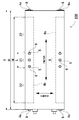
- the bolts 5 arranged at five locations in the center (point A), both ends (point C), and between the center and both ends (point B) of the cooling plate 9 cool the bind bar 4. It is a bottom view of the power supply device fixed to the plate 9.
- the difference ( ⁇ 1) in the amount of expansion and contraction due to the temperature change of the point B is It is 1/2 of the difference ( ⁇ 2) in the amount of expansion and contraction. Therefore, the bolt 5 at point B has little difference (.DELTA.1) in the amount of expansion or contraction due to temperature change between the bind bar 4 and the cooling plate 9, and loosening due to relative displacement between the bind bar 4 and the cooling plate 9 is prevented. Ru. Therefore, the power supply apparatus in which the fixing area 21 between the bind bar 4 and the cooling plate 9 is located between the points B disposed on both sides of the point A fixes the bind bar and the cooling plate with bolts to both ends (point C). Compared with the power supply unit, it has the feature of being able to prevent the loosening of the bolt.
- the power supply unit that fixes the bind bar to the cooling plate with a thick bolt has a coolant passage provided in the cooling plate because the bolt is bulky and the outer shape is enlarged and the thick bolt is screwed or penetrated into the cooling plate. As it narrows, the entire cooling plate can not be cooled uniformly.
- the power supply device that fixes the bind bar to the cooling plate with a thin bolt can prevent the bolt from becoming bulky and can reduce the outer diameter, and by narrowing the bolt, the refrigerant passage provided in the cooling plate becomes narrow. Can be realized to realize the feature that the entire cooling plate can be uniformly cooled.
- the bind bar 4 is made of iron or iron alloy
- the cooling plate 9 is made of aluminum or aluminum alloy. Further, the cooling plate 9 preferably has a total length (R) of 30 cm or more.
- the bind bar 4 has a bent portion 4 b fixed to the surface of the cooling plate 9, and fixes the bind bar 4 to the cooling plate 9 via a bolt 5 penetrating the bent portion 4 b. It may be
- the power supply device may be configured to dispose the bent portion 4 b on the outer surface of the cooling plate 9 and to fix the bent portion 4 b to the outer surface of the cooling plate 9.
- the power supply device may be configured such that the bent portion 4 b is disposed between the cooling plate 9 and the battery stack 2 and the bent portion 4 b is fixed to the surface of the cooling plate 9 facing the battery stack 2.
- the bolt 5 may be screwed into a female screw hole 9 a provided in the cooling plate 9 to be fixed.
- the nut 6 may be screwed into the bolt 5 and the cooling plate 9 may be sandwiched between the bolt 5 and the nut 6 to fix the bind bar 4 to the cooling plate 9.
- the cooling plate 9 may have flange portions 9Y extending in the longitudinal direction on both sides, and the battery stack 2 may be fitted inside the flange portions 9Y.
- the power supply device may be configured to dispose the heat conduction sheet 32 between the battery stack 2 and the cooling plate 9.
- each element constituting the present invention may be configured such that a plurality of elements are constituted by the same member and one member is used in common as a plurality of elements, or conversely, the function of one member is realized by a plurality of members It can be shared and realized.
- the contents described in some examples and embodiments may be applicable to other examples and embodiments.
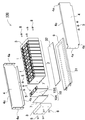
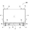
- a power supply device 100 shown in FIGS. 1 to 4 includes a battery stack 2 in which a plurality of battery cells 1 are stacked, and a pair of end plates 3 disposed at both ends in the stacking direction of the battery stack 2.
- a bind bar 4 connecting both end portions to the end plate 3 to restrain the plurality of battery cells 1 in the stacking direction, and a cooling plate 9 disposed in a thermally coupled state on the surface of the battery stack 2 Prepare.
- the battery cell 1 is a rectangular battery whose width is wider than the thickness, in other words, thinner than the width, and is stacked in the thickness direction to form a battery stack 2.
- the battery cell 1 is a non-aqueous electrolytic solution battery in which the battery case 10 is a metal case.
- the battery cell 1 which is a non-aqueous electrolyte solution battery is a lithium ion secondary battery.
- the battery cell can also be a secondary battery such as a nickel hydrogen battery or a nickel cadmium battery.
- the battery cell 1 in the figure is a battery in which both wide surfaces are square, and is stacked to face each other to form a battery stack 2.
- an electrode body (not shown) is accommodated in a metal battery case 10 having a rectangular outer shape and filled with an electrolytic solution.
- the battery case 10 formed of a metal case can be manufactured of aluminum or an aluminum alloy.
- the battery case 10 includes an outer can 10A in which a metal plate is pressed in a cylindrical shape closing the bottom, and a sealing plate 10B airtightly closing an opening of the outer can 10A.
- the sealing plate 10B is a flat metal plate, and the outer shape thereof is the shape of the opening of the outer can 10A.
- the sealing plate 10B is fixed by laser welding to the outer peripheral edge of the outer can 10A to airtightly close the opening of the outer can 10A.
- the sealing plate 10B fixed to the outer can 10A fixes the positive and negative electrode terminals 13 at both ends, and further, a gas discharge port 12 is provided between the positive and negative electrode terminals 13.
- a discharge valve 11 which opens at a predetermined internal pressure is provided inside the gas discharge port 12.
- the battery stacks 2 shown in FIGS. 1 and 2 are formed by laminating the plurality of battery cells 1 in a posture in which the surfaces provided with the discharge valves 11 are substantially on the same surface, and the discharge valves 11 of the respective battery cells 1 are identical. It is arranged on the plane. In the illustrated battery stack 2, the plurality of battery cells 1 are stacked in a posture in which the sealing plate 10 ⁇ / b> B provided with the discharge valve 11 is an upper surface.
- a plurality of battery cells 1 stacked on one another are connected in series and / or in parallel to one another by connecting positive and negative electrode terminals 13.
- the power supply device 100 connects the positive and negative electrode terminals 13 of adjacent battery cells 1 in series and / or in parallel with each other via a bus bar (not shown).
- a power supply device in which adjacent battery cells are connected in series can increase the output voltage to increase the output, and can connect adjacent battery cells in parallel to increase the charge / discharge current.
- Battery stack 2 In a battery stack 2 shown in FIG. 2, a plurality of battery cells 1 are stacked on one another via a spacer 7, and these battery cells 1 are connected in series.
- the battery stack 2 of FIG. 1 arranges the battery cells 1 adjacent to each other in the opposite direction, connects the adjacent electrode terminals 13 on both sides with a bus bar, and serially connects the two adjacent battery cells 1 It connects, and all the battery cells 1 are connected in series.
- the present invention does not specify the number of battery cells constituting the battery stack and the connection state thereof.
- the spacers 7 are sandwiched between the battery cells 1 stacked, and the adjacent battery cells 1 are stacked in an insulating state.
- the spacer 7 is an insulating plate formed of plastic in a plate shape.
- the spacer 7, which is formed of a plastic having a low thermal conductivity, has an effect of being able to effectively prevent the thermal runaway of the adjacent battery cells 1.
- the spacer 7 can be stacked so that the adjacent battery cells 1 are not misaligned as a shape in which the battery cells 1 are fitted and disposed at a predetermined position.
- the outer can can be made of metal such as aluminum.
- a spacer is formed by insulating battery cells adjacent to each other by a method such as forming an outer can of a battery cell with an insulating material, or coating the outer periphery of an outer can of a battery cell with an insulating sheet or insulating paint. Because it is unnecessary.
- a battery stack in which no spacer is interposed between battery cells is a system in which direct cooling is performed using a refrigerant or the like without adopting an air-cooling type that cools the battery cells by forcibly blowing cooling air between the battery cells. Can be used to cool the battery cell.
- End plate 3 The end plate 3 is connected to the bind bar 4 and arranges the battery stack 2 on both end faces to hold the battery cell 1 in the stacking direction.
- the end plate 3 is fixed to the bind bar 4 to fix each battery cell 1 of the battery stack 2.
- the outer shape of the end plate 3 is almost equal to or slightly larger than the outer shape of the battery cell 1, and the bind bar 4 is fixed to the outer peripheral surface of both sides to move the cell stack 2 even during vibration / impact Is a square plate having a strength to suppress
- the end plate 3 is entirely made of metal such as aluminum or aluminum alloy.
- the end plate may have a structure in which a metal plate is laminated on plastic, or alternatively, the whole may be a fiber reinforced resin molded plate in which reinforcing fibers are embedded.
- the end plate 3 is in close contact with the surface of the battery cell 1 directly or via a spacer to fix the battery cell 1.
- the power supply device 100 arranges the end plates 3 at both ends of the battery stack 2 in the assembly process, and press the end plates 3 at both ends with a press (not shown) to insert the bind bar 4. After the end plate 3 is fixed to the bind bar 4, the pressing state of the press is released.
- the cooling plate 9 cools the battery cell 1 with a coolant circulating inside.
- the cooling plate 9 is made of a metal plate such as aluminum or an aluminum alloy excellent in heat conduction characteristics.
- the cooling plate 9 is provided with a circulation path 31 for the cooling fluid inside.
- the circulation path 31 is connected to the cooling mechanism 30 to cool the cooling plate 9.
- the cooling plate 9 is disposed in a thermally coupled state on the bottom surface of the battery stack 2.
- the cooling plate 9 can also be disposed on the side surface of the battery stack 2.
- the power supply device 100 of the figure is configured to cool all the battery cells 1 as a rectangular metal plate having an outer shape of the cooling plate 9 equal to or slightly larger than the bottom shape of the battery stack 2.
- a metal pipe is inserted into the inside of a metal plate to provide a cavity, or a cavity is provided therein, and a coolant circulation passage 31 is provided inside.
- FIG. 3 and 5 are schematic cross-sectional views of the power supply devices 100, 200.
- the heat transfer sheet 32 is a sheet having flexibility and cushioning properties and excellent heat transfer characteristics.
- the heat conductive sheet 32 is sandwiched between the battery stack 2 and the cooling plate 9, and one surface is in close contact with the surface of the battery stack 2 and the other surface is in close contact with the surface of the cooling plate 9.
- the battery stack 2 and the cooling plate 9 are disposed in an ideal thermal coupling state.
- the cooling plate 9 is fixed in close contact with the surface of the battery stack 2 via the bind bar 4.
- the power supply device 100 of FIG. 1 and FIG. 2 bends both ends of the bind bar 4 inward to provide a fixing piece 4a, and fixes the fixing piece 4a to the surface of the end plate 3 via a fixing screw 8. ing.
- the present invention does not specify a structure for fixing the bind bar 4 to the end plate 3, all other fixing structures capable of firmly fixing both ends of the bind bar 4 to the end plate 3 can be used.
- the bind bar 4 shown in the figure is provided at the upper end with an upper bent piece 4c which is bent inward.
- the upper bent pieces 4c are disposed on the upper surfaces on both sides of the battery stack 2, and the terminal surfaces which are the upper surfaces of the plurality of stacked battery cells 1 are disposed on the same plane.
- the cooling plate 9 is fixed to the bind bar 4 and fixed to the battery stack 2 in a thermally coupled state.
- the bind bar 4 shown in the schematic cross sectional views of FIGS. 3 and 5 is provided with a bent portion 4 b fixed to the surface of the cooling plate 9.
- the bent portion 4 b is provided by bending the lower edge of the bind bar 4 inward.
- the bind bar 4 is fixed to the cooling plate 9 via a bolt 5 penetrating the bent portion 4b.
- the bent portion 4 b of the bind bar 4 is disposed on the outer surface of the cooling plate 9, and the bent portion 4 b is fixed to the outer surface of the cooling plate 9.
- the power supply device 100 fixes the bind bar 4 to the cooling plate 9 by screwing a bolt 5 penetrating the bent portion 4 b into a female screw hole 9 a provided on the bottom surface of the cooling plate 9.
- the bent portion 4 b of the bind bar 4 is disposed between the battery stack 2 and the cooling plate 9, and the bent portion 4 b is fixed to the surface of the cooling plate 9 facing the battery stack 2. doing.
- a nut 6 is screwed into a bolt 5 penetrating the bent portion 4b and the cooling plate 9, and the bind bar 4 is held by sandwiching the bent portion 4b and the cooling plate 9 with the bolt 5 and the nut 6. It is fixed to the cooling plate 9.
- the cooling plate 9 is provided with a through hole 9 b through which the bolt 5 is inserted.
- the bolt 5 may be caulked or welded to the bind bar 4.
- the bind bar 4 fixes both ends to the end plate 3 to restrain the battery cell 1 of the battery stack 2 in the stacking direction.
- the bind bar 4 is subjected to a strong tensile force by a load from the battery stack 2 at the time of vibration and impact.
- the bind bar 4 is made of high-tensile steel or stainless steel.
- the cooling plate 9 is required to have excellent heat transfer characteristics, and the bind bar 4 is required to have a property to withstand a strong tensile force, so that the cooling plate 9 and the bind bar 4 are made of different metals.
- the cooling plate 9 and the bind bar 4 of dissimilar metals have different amounts of expansion and contraction with respect to temperature change, and for example, the coefficient of thermal expansion of aluminum is about twice that of steel. Therefore, the cooling plate 9 made of aluminum has twice as much expansion and contraction amount with respect to a temperature change as compared with the bind bar 4 of high tensile steel.
- a relative shift occurs between the dissimilar metals due to temperature change. Deviations between dissimilar metals due to temperature changes occur at the junction of the bind bar 4 and the cooling plate 9.
- the bind bar 4 of the dissimilar metal and the cooling plate 9 move relative to each other due to the temperature change, which causes the bolt 5 to be loosened.
- the power supply device is used in an extremely wide pressing range, the relative movement with respect to the temperature change is large, which causes the bolt 5 to be loosened.
- FIG. 4 and 6 are bottom views of the power supply devices 100 and 200 for preventing the bolt 5 from loosening due to temperature change.
- 4 is a bottom view of the power supply apparatus 100 of FIG. 3
- FIG. 6 is a bottom view of the power supply apparatus 200 of FIG.
- the power supply devices 100 and 200 shown in these figures do not fix the end of the bent portion 4b of the bind bar 4 to the cooling plate 9 with a bolt.
- the bent portion 4 b is fixed to the cooling plate 9 via a plurality of bolts 5 in order to firmly fix it to the cooling plate 9.
- the structure for fixing the bind bar 4 to the cooling plate 9 with a plurality of bolts 5 can firmly fix the bind bar 4 to the cooling plate 9 with the thin bolts 5.
- the bind bar 4 can be fixed to the cooling plate 9 with one thick and strong bolt 5, the thick bolt 5 is large and bulky, so that the outer shape of the power supply device becomes large. Further, when the thick bolt 5 is screwed into or penetrated through the cooling plate 9, the volume of the circulation path 31 provided inside the cooling plate 9 is limited, which causes a problem that the whole can not be efficiently cooled. In order to prevent this harmful effect, the bind bar 4 is fixed to the cooling plate 9 by a plurality of bolts 5.
- the non-fixed area 22 where the bind bar 4 is not fixed by the bolt 5 is provided at the end of the bind bar 4 as 70% or less of the total length (T) of the bind bar 4.
- the fixed area 21 is provided at the center of the bent portion 4b, and the non-fixed area 22 having the same length is provided at both ends.
- the power supply devices 100 and 200 are characterized in that the bind bar 4 can be securely fixed to the cooling plate 9 in an ideal state. However, the fixed area does not necessarily have to be disposed at the center of the fold.
- the fixed area 21 with respect to the entire length (T) of the bind bar 4 can be reduced in length (L) to reduce loosening of the bolt 5 due to temperature change. Further, the fixing area 21 can be made longer to fix the bind bar 4 to the cooling plate 9 more reliably. Furthermore, since the loosening of the bolt 5 due to the temperature change also changes with the total length (R) of the cooling plate 9, that is, the total length (T) of the bind bar 4, the length of the fixing area 21 with respect to the total length (T) of the bind bar 4 (L) is set to an optimal value in consideration of the total length (T) of the bind bar 4 as well.
- the power supply devices 100 and 200 set the length (L) of the fixed area 21 to 70% or less of the total length (T) of the bind bar 4 or the total length (R) of the cooling plate 9.
- the length (L) of the fixing area 21 with respect to the total length (T) of the bind bar 4 is the bolt 5 loosening due to temperature change and the bind bar 4 fixed to the cooling plate 9
- the strength it is limited to, for example, 60% or less, preferably 50% or less, and more preferably 40% or less.
- the power supply devices 100 and 200 of FIGS. 4 and 6 three bolts 5 are arranged side by side in the fixing area 21 provided at the center of the bent portion 4 b of the bind bar 4 and the fixing area fixing the bolts 5.
- the length 21 (L) is 20% of the total length (M) of the bent portion 4b of the bind bar 4, and 80% non-fixed regions 22 of the total length (M) of the bent portion 4b are provided at both ends. .
- the power supply device 100, 200 has a short length (L) of the fixed area 21, it is characterized in that the loosening of the bolt 5 can be reliably prevented even when used for a long time in an environment with a significant temperature change. is there.
- the above power supply device arranges three bolts 5 in the fixed area 21 and fixes the bind bar 4 to the cooling plate 9, but arranges two or four or more bolts 5 in the fixed area 21.
- the bind bar 4 can also be fixed to the cooling plate 9.
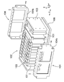
- the power supply devices 300 and 400 shown in the schematic cross sectional views of FIGS. 7 and 8 are provided with flange portions 9Y extending along the longitudinal direction on both sides of the cooling plate 9, and the battery stack 2 is provided inside the flange portions 9Y on both sides. Are placed in the fitted state.
- the main body 9X is in close thermal contact with the bottom of the battery stack 2 and the inner surface of the flange 9Y is in close thermal contact with both sides of the battery stack 2.
- the battery stack 2 is disposed inside the flanges 9Y on both sides, and the position in the width direction (X-axis direction in FIGS. 4 and 6) between the cooling plate 9 and the battery stack 2. Stop the gap. Therefore, the connection rigidity of both can be enhanced in the X-axis direction.
- the power supply devices 300, 400 prevent positional deviation of the battery stack 2 and the cooling plate 9 in the longitudinal direction (Y-axis direction in FIGS.
- the power supply devices 300 and 400 prevent positional deviation in the X-axis direction with the flange portion 9Y, so only the positional deviation in the Y-axis direction is prevented with the bolt 5 to ensure the battery stack 2 and the cooling plate 9 reliably. It can be fixed not to be misaligned. Therefore, the power supply devices 300 and 400 of this structure shorten the length (L) of the fixing area 21 and effectively prevent the loosening of the bearing surface of the bolt 5 while the cooling plate 9 and the battery stack 2 are There is a feature that can be firmly connected in an ideal state without misalignment.
- the cooling plate 9 described above can be formed by die-casting or extruding aluminum to provide the flange portion 9Y in an integral structure. However, it is also possible to fix the flange portion 9Y as a separate member to the main body portion 9X.
- the power supply device of the above-described embodiment is configured to include the cooling plate 9 that cools the battery cell 1 with the coolant circulating in the inside, in the present invention, the cooling plate does not necessarily cool the inside of the plate.
- the configuration may not be such that the liquid circulates.
- the cooling plate may be a heat conducting plate formed by molding a highly heat conductive material such as aluminum. In this configuration, the battery cells can be cooled by utilizing the thermal conductivity of the plate, and since it is not necessary to circulate the coolant or the like, the configuration can be simplified. These may be selected according to the required cooling performance.
- the power supply devices 100 and 300 of FIGS. 1 to 4 and FIG. 7 are assembled in the following steps.
- a predetermined number of battery cells 1 are stacked in the thickness direction of the battery cells 1 with the spacers 7 interposed therebetween to form a battery stack 2.
- the end plates 3 are disposed at both ends of the battery stack 2, and the pair of end plates 3 are pressed from both sides by a press (not shown) and held.
- the cooling plate 9 is disposed on the bottom of the battery stack 2 via the heat conductive sheet 32.
- the battery stack 2 is fitted between the flange portions 9 ⁇ / b> Y provided on both sides of the cooling plate 9.
- the facing electrode terminals 13 of the battery cells 1 adjacent to each other are connected by a bus bar (not shown).
- the bus bar is fixed to the electrode terminal 13 to connect the battery cells 1 in series or in parallel to the series.
- the bus bar is welded or screwed to the electrode terminal 13 and fixed to the electrode terminal 13.
- the power supply devices 200 and 400 of FIG. 5, FIG. 6, and FIG. 8 are assembled in the following steps.
- Bind bars 4 are connected and fixed to the pair of end plates 3 in a compressed state with the end plate 3 of the battery stack 2.
- fixing pieces 4 a provided at both ends are fixed to the outer surface of the end plate 3 via fixing screws 8.
- the battery stack 2 is held via the pair of end plates 3 held at predetermined intervals by the bind bar 4.
- the bent portion 4 b of the bind bar 4 is fixed to the cooling plate 9.
- the bent portion 4 b is disposed between the cooling plate 9 and the battery stack 2, and is fixed to the surface of the cooling plate 9 facing the battery stack 2.
- the bolt 5 passing through the bent portion 4 b is inserted into the through hole 9 b of the cooling plate 9, and the nut 6 is screwed into the bolt 5 to clamp the cooling plate 9 with the bolt 5 and the nut 6. It is fixed.
- the heat conduction sheet 32 is interposed between the battery stack 2 and the cooling plate 9.
- the battery stack 2 is fitted between the flanges 9 Y provided on both sides of the cooling plate 9, and the flanges 9 Y are disposed on the outer surface of the bind bar 4.
- the facing electrode terminals 13 of the battery cells 1 adjacent to each other are connected by a bus bar (not shown).
- the bus bar is fixed to the electrode terminal 13 to connect the battery cells 1 in series or in parallel to the series.
- the bus bar is welded or screwed to the electrode terminal 13 and fixed to the electrode terminal 13.
- the above power supply device is most suitable for a power supply device for a vehicle that supplies electric power to a motor for traveling an electric vehicle.
- a power supply device for a vehicle that supplies electric power to a motor for traveling an electric vehicle.
- an electric vehicle carrying a power supply device an electric vehicle such as a hybrid car or plug-in hybrid car traveling with both an engine and a motor or an electric car traveling only with a motor can be used. Be done.
- FIG. 9 shows an example in which the power supply device is mounted on a hybrid vehicle traveling with both an engine and a motor.
- the vehicle HV equipped with the power supply device shown in this figure includes a vehicle body 90, an engine 96 for traveling the vehicle body 90, a motor 93 for traveling, a power supply device 100 for supplying power to the motor 93, and a power supply device 100.
- a generator 94 for charging the battery, and a wheel 97 driven by the motor 93 and the engine 96 to travel the vehicle body 90 are provided.
- the power supply device 100 is connected to the motor 93 and the generator 94 via a DC / AC inverter 95.
- the vehicle HV travels with both the motor 93 and the engine 96 while charging and discharging the battery of the power supply device 100.
- the motor 93 is driven in a region where the engine efficiency is low, for example, at the time of acceleration or low speed traveling to drive the vehicle.
- the motor 93 is supplied with power from the power supply device 100 and is driven.
- the generator 94 is driven by the engine 96 or driven by regenerative braking when the vehicle is braked to charge the battery of the power supply device 100.
- FIG. 10 shows an example in which the power supply device is mounted on an electric vehicle traveling only by a motor.
- the vehicle EV mounted with the power supply device shown in this figure includes a vehicle body 90, a traveling motor 93 for traveling the vehicle body 90, a power supply device 100 for supplying power to the motor 93, and a battery of the power supply device 100. And a wheel 97 driven by a motor 93 to travel the vehicle body 90.
- the motor 93 is supplied with power from the power supply device 100 and is driven.
- the generator 94 is driven by energy when regenerative braking the vehicle EV, and charges the battery of the power supply device 100.
- the present invention does not specify the use of the power supply device as a power supply device mounted on an electric vehicle, and can be used as a power supply device for a storage device for storing natural energy such as solar power generation and wind power generation. It can be used for all applications that store large electric power, such as a power supply device for a power storage device that stores electric power.
- a power supply for home use or factory use a power supply system that charges with sunlight or late-night power and discharges it when necessary, or a streetlight power supply that charges sunlight during the day and discharges it at night, It can also be used as a backup power supply for driving traffic signals.
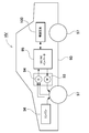
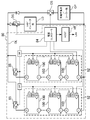
- FIG. Note that, in the usage example as a power storage device shown in FIG. 11, in order to obtain desired power, a large number of high-power, high-power devices are obtained by connecting many of the above-described power supply devices in series or in parallel and adding necessary control circuits. Description will be made as an example in which power storage device 80 is constructed.
- a power storage device 80 shown in FIG. 11 configures a power supply unit 82 by connecting a plurality of power supply devices 100 in a unit form.
- a plurality of battery cells are connected in series and / or in parallel.
- Each power supply device 100 is controlled by a power supply controller 84.
- the power storage device 80 drives the load LD after charging the power supply unit 82 with the charging power supply CP. Therefore, power storage device 80 has a charge mode and a discharge mode.
- the load LD and the charging power supply CP are connected to the storage device 80 through the discharge switch DS and the charging switch CS, respectively.
- the ON / OFF of the discharge switch DS and the charge switch CS is switched by the power controller 84 of the power storage device 80.
- the power supply controller 84 switches the charge switch CS to ON and the discharge switch DS to OFF to allow charging of the storage battery 80 from the charging power supply CP. Also, when the charging is completed and the battery is fully charged, or when the capacity more than a predetermined value is charged, the power supply controller 84 turns off the charging switch CS and turns on the discharging switch DS to discharge in response to a request from the load LD. It switches to the mode and permits discharge from the storage device 80 to the load LD. In addition, if necessary, the charge switch CS can be turned on and the discharge switch DS can be turned on to simultaneously perform the power supply of the load LD and the charging of the power storage device 80.
- the load LD driven by the storage device 80 is connected to the storage device 80 via the discharge switch DS.
- the power supply controller 84 switches the discharge switch DS to ON, connects it to the load LD, and drives the load LD with the power from the storage device 80.
- the discharge switch DS can use a switching element such as an FET.
- the ON / OFF of the discharge switch DS is controlled by the power supply controller 84 of the power storage device 80.
- the power supply controller 84 also includes a communication interface for communicating with an external device. In the example of FIG. 11, the host device HT is connected according to the existing communication protocol such as UART or RS-232C. Also, if necessary, a user interface may be provided for the user to operate the power supply system.
- Each power supply device 100 includes a signal terminal and a power terminal.
- the signal terminals include an input / output terminal DI, an abnormal output terminal DA, and a connection terminal DO.
- the input / output terminal DI is a terminal for inputting / outputting a signal from another power supply apparatus 100 or a power supply controller 84
- the connection terminal DO is a terminal for inputting / outputting a signal to / from the other power supply apparatus 100.
- the abnormality output terminal DA is a terminal for outputting the abnormality of the power supply device 100 to the outside.
- the power supply terminal is a terminal for connecting the power supply devices 100 in series and in parallel.
- the power supply units 82 are connected to the output line OL via the parallel connection switch 85 and connected in parallel to each other.
- the power supply device according to the present invention, a vehicle including the same, and a power storage device are suitably used as a power supply device for a plug-in hybrid electric vehicle, a hybrid electric vehicle, an electric vehicle or the like capable of switching between the EV travel mode and the HEV travel mode. it can.
- a backup power supply that can be mounted in a rack of a computer server, a backup power supply for a wireless base station such as a mobile phone, a storage power for household use and a factory, a power supply for street lights, etc. It can also be suitably used for backup power sources such as traffic lights.
- Cooling plate 9 Main body portion 9Y: Flange portion 9a: female screw hole 9b: through hole 10: battery case 10A: outer package can DESCRIPTION OF SYMBOLS 10B ... Sealing plate, 11 ... Discharge valve, 12 ... Gas discharge port, 13 ... Electrode terminal, 21 ... Fixed area, 22 ... Non-fixed area, 30 ... Cooling mechanism, 31 ... Circulation path, 32 ...
- Heat conduction sheet 80 ... Storage device, 82: power supply unit, 84: power supply controller, 85: parallel connection switch, 90: vehicle body, 93: motor, 94: generator, 95: DC / AC inverter, 96: engine, 97: wheel, 101: 101 Electricity Cell 102 102 battery stack 103 end plate 104 bind bar 104b bent portion 109 cooling plate EV: vehicle HV: vehicle load: CP charge power source: DS discharge switch , CS ... charge switch, OL ... output line, HT ... host device, DI ... input / output terminal, DA ... abnormal output terminal, DO ... connection terminal
Abstract
In order to keep a cooling plate and a battery stack in an ideal thermally bonded state by preventing looseness of a bolt over a long period while securing the cooling plate to the battery stack via the bolt, in this power supply device, both ends of a binding bar (4) are coupled to a pair of end plates disposed at both ends in the stacking direction of a battery stack formed by stacking a plurality of battery cells, thereby securing the plurality of battery cells in the stacking direction, a cooling plate (9) formed of a different type of metal from that of the binding bar (4) is disposed in a thermally coupled state on the surface of the battery stack, and the cooling plate (9) is secured to the battery stack via a plurality of bolts (5) disposed in the longitudinal direction of the battery stack. In the power supply device, the length (L) of a secured region (21) where the binding bar (4) is secured to the cooling plate (9) via the plurality of bolts (5) is set to 70% or less of the total length (T) of the binding bar (4), and a unsecured region (22) that is not secured to the cooling plate (9) via the bolt (5) is provided at an end of the binding bar (4).
Description
本発明は、複数の電池セルを積層して電池積層体とし、この電池積層体の両端に配置してなるエンドプレートを介して熱伝導プレートを電池積層体に熱結合状態に配置してなる電源装置及び電源装置を備える車両並びに蓄電装置に関する。
The present invention is a power supply in which a plurality of battery cells are stacked to form a battery stack, and a heat conduction plate is disposed thermally coupled to the battery stack through end plates disposed at both ends of the battery stack. The present invention relates to a vehicle including a device and a power supply device and a power storage device.
典型的な電源装置は、複数の角形電池セルからなる電池積層体と、電池積層体の両端面に配置される一対のエンドプレートと、一対のエンドプレートを連結するバインドバーとを備えている。この電源装置は、電池積層体をエンドプレートとバインドバーにより拘束することで、複数の角形電池セルからなる電池積層体を集合化できるようになっている。さらに、電池積層体を構成する複数の電池セルを効率よく冷却するために、電池積層体の表面に冷却プレートを熱結合状態で配置して強制的に冷却する構造の電源装置が開発されている。(特許文献1参照)
A typical power supply device includes a battery stack including a plurality of rectangular battery cells, a pair of end plates disposed on both end surfaces of the battery stack, and a bind bar connecting the pair of end plates. This power supply device is configured to be able to aggregate the battery stack composed of a plurality of rectangular battery cells by restraining the battery stack by the end plate and the bind bar. Furthermore, in order to efficiently cool a plurality of battery cells constituting a battery stack, a power supply device having a structure in which a cooling plate is disposed in a thermally coupled state on the surface of the battery stack and forced cooling is developed. . (See Patent Document 1)
冷却プレートで電池セルを冷却する電源装置は、例えば、複数のボルトを介して冷却プレートが電池積層体に固定される。ただ、この構造の電源装置は、冷却プレートを固定するボルトが経時的に緩むことがある。このボルトが緩むと、冷却プレートと電池積層体との熱結合状態が悪化して電池セルの冷却効率が低下する虞がある。また、ボルトの緩みは、振動による騒音の原因となり、また脱落するとさらに種々の故障の原因となるため決して好ましくなく、これを極減することが切望されている。
In the power supply device that cools the battery cells with the cooling plate, for example, the cooling plate is fixed to the battery stack via a plurality of bolts. However, in the power supply of this structure, the bolt for fixing the cooling plate may be loosened over time. When the bolt is loosened, the thermal coupling between the cooling plate and the battery stack may be deteriorated, which may reduce the cooling efficiency of the battery cell. In addition, loose bolts are a source of noise due to vibration, and dropping off is a cause of various failures.
本発明は、以上の欠点を解決することを目的に開発されたもので、本発明の重要な目的は、ボルトを介して冷却プレートを電池積層体に固定する構造としながら、長期間にわたってボルトの緩みを防止して、冷却プレートと電池積層体とを理想的な熱結合状態に維持できる技術を提供することにある。
The present invention was developed for the purpose of solving the above-mentioned drawbacks, and an important object of the present invention is to fix the cooling plate to the battery stack through the bolt, while maintaining the bolt over a long period of time. It is an object of the present invention to provide a technology capable of preventing loosening and maintaining the cooling plate and the battery stack in an ideal thermal bond.
本発明のある態様の電源装置は、複数の電池セルを積層してなる電池積層体と、前記電池積層体の積層方向の両端部に配置してなる一対のエンドプレートと、両端部を一対の前記エンドプレートに連結して、複数の前記電池セルを積層方向に拘束するバインドバーと、前記電池積層体の表面に熱結合状態に配置してなる前記バインドバーと異種金属の冷却プレートとを備え、前記電池積層体の長手方向に配置してなる複数のボルトを介して前記冷却プレートを前記電池積層体に固定している。電源装置は、複数の前記ボルトが前記バインドバーを前記冷却プレートに固定してなる固定領域の長さ(L)を、前記バインドバーの全長(T)の70%以下として、前記バインドバーの端部に、前記ボルトを介して前記冷却プレートに固定されない非固定領域を設けている。
A power supply device according to an aspect of the present invention includes a battery stack formed by stacking a plurality of battery cells, a pair of end plates disposed at both ends in the stacking direction of the battery stack, and a pair of both ends. It comprises: a bind bar coupled to the end plate to restrain the plurality of battery cells in the stacking direction; the bind bar disposed in a thermally coupled state on the surface of the battery stack; and a cooling plate of dissimilar metal The cooling plate is fixed to the battery stack via a plurality of bolts arranged in the longitudinal direction of the battery stack. The power supply apparatus sets the length (L) of the fixing area formed by fixing the bind bar to the cooling plate by a plurality of bolts as 70% or less of the total length (T) of the bind bar, the end of the bind bar The part is provided with a non-fixing area which is not fixed to the cooling plate via the bolt.
さらに、以上の態様の構成要素を備えた電源装置を備える電動車両は、前記電源装置と、該電源装置から電力供給される走行用のモータと、該電源装置及び前記モータを搭載してなる車両本体と、該モータで駆動されて前記車両本体を走行させる車輪とを備えている。
Furthermore, an electric vehicle including a power supply device including the components of the above aspect includes the power supply device, a traveling motor powered by the power supply device, and a vehicle equipped with the power supply device and the motor. A main body and a wheel driven by the motor to travel the vehicle main body are provided.
さらに、以上の態様の構成要素を備えた電源装置を備える蓄電装置は、前記電源装置と、該電源装置への充放電を制御する電源コントローラを備え、前記電源コントローラが外部からの電力による前記電池セルへの充電を可能とすると共に、該電池セルに対し充電を行うよう制御している。
Further, a power storage device including a power supply device including the components of the above aspect includes the power supply device and a power supply controller for controlling charging and discharging of the power supply device, and the power supply controller is the battery using external power. The battery can be charged, and the battery cell is controlled to be charged.
本発明は、電源装置を簡単な構造としながら、複数のボルトを介して冷却プレートを電池積層体に理想的な状態で固定でき、さらに、長期間にわたってボルトの緩みを防止して、冷却プレートと電池積層体とを理想的な熱結合状態に維持できる特徴がある。それは、以上の電源装置が、電池積層体を積層方向に拘束する一対のエンドプレートに両端を連結しているバインドバーを、複数のボルトで冷却プレートに固定して、冷却プレートを電池積層体の表面に配置すると共に、複数のボルトがバインドバーを冷却プレートに固定してなる固定領域の長さ(L)を、バインドバーの全長(T)の70%以下として、バインドバーの端部に、ボルトを介して冷却プレートに固定されない非固定領域を設けているからである。
According to the present invention, the cooling plate can be ideally fixed to the battery stack through a plurality of bolts while the power supply device has a simple structure, and furthermore, the bolt can be prevented from loosening over a long period of time. There is a feature that can maintain an ideal thermal bond with the battery stack. That is, the power supply device fixes a bind bar, which is connected at both ends to a pair of end plates that restrains the battery stack in the stacking direction, to the cooling plate with a plurality of bolts, At the end of the binding bar, the length (L) of the fixing area, which is arranged on the surface and in which the plurality of bolts fix the binding bar to the cooling plate, is 70% or less of the total length (T) of the binding bar It is because the non-fixed area which is not fixed to the cooling plate via the bolt is provided.
まず、本発明の一つの着目点について説明する。ハイブリッドカーや電気自動車等の車両に搭載される大電力の電源装置は、充放電の電流が大きく、また種々の外的条件で使用されることから電池温度が大幅に変動する。とくに、電池の温度上昇は、充放電できる電流範囲を制限し、寿命を短くして安全性を阻害する原因となるので、冷却プレートで電池を強制的に冷却する構造の電源装置が開発されている。
First, one focus point of the present invention will be described. High-power power supply devices mounted on vehicles such as hybrid cars and electric vehicles have large charging and discharging currents and are used under various external conditions, resulting in significant fluctuations in battery temperature. In particular, since the temperature rise of the battery limits the range of current that can be charged and discharged, and shortens the life and hinders safety, a power supply device having a structure in which the battery is forcibly cooled by a cooling plate has been developed. There is.
従来の電源装置は、図13に示すように、複数の電池セル101を積層している電池積層体102の底面に冷却プレート109を配置して、冷却プレート109で電池セル101を冷却している。図の電源装置は、バインドバー104の下縁に折り曲げ部104bを設けて、この折り曲げ部104bを冷却プレート109に固定して、冷却プレート109を電池積層体102の底面に配置している。バインドバー104は、電池積層体102の両端に配置するエンドプレート103に両端を固定して、電池積層体102を拘束している。この図に示すように、折り曲げ部104bを冷却プレート109に固定して、冷却プレート109を電池積層体102の底面に配置する電源装置は、冷却プレート109を電池積層体102の底面に密着して好ましい熱結合状態に固定できる。電池積層体102の積層方向に伸びるバインドバー104は、細長い折り曲げ部104bを複数のボルトで冷却プレート109に固定して、冷却プレート109を好ましい状態で電池セル101の底面に熱結合状態に配置できる。
In the conventional power supply device, as shown in FIG. 13, cooling plate 109 is disposed on the bottom surface of battery stack 102 in which a plurality of battery cells 101 are stacked, and cooling battery cell 101 is cooled by cooling plate 109. . In the illustrated power supply apparatus, a bent portion 104 b is provided at the lower edge of the bind bar 104, the bent portion 104 b is fixed to the cooling plate 109, and the cooling plate 109 is disposed on the bottom of the battery stack 102. The bind bar 104 fixes both ends to end plates 103 disposed at both ends of the battery stack 102 to restrain the battery stack 102. As shown in this figure, the power supply device in which the bent portion 104 b is fixed to the cooling plate 109 and the cooling plate 109 is disposed on the bottom of the battery stack 102 is in close contact with the cooling plate 109 on the bottom of the battery stack 102. It can be fixed in a preferred thermal bond. The bind bar 104 extending in the stacking direction of the battery stack 102 can fix the elongated bent portion 104 b to the cooling plate 109 with a plurality of bolts and place the cooling plate 109 in a thermally coupled state on the bottom surface of the battery cell 101 in a preferable state. .
ボルトは、折り曲げ部の長手方向に並べて配置されて、細長い折り曲げ部を冷却プレートに固定できる。この固定構造は、複数のボルトで冷却プレートを電池積層体の底面に、好ましい熱結合状態に配置できる。ただ、この構造の電源装置は、大幅に変動する温度環境で長期間使用されると、バインドバーと冷却プレートとが相対的に移動してボルトが緩む弊害が発生する。ボルトが緩むと、冷却プレートと電池積層体との熱結合状態が悪化して、冷却プレートによる各々の電池セルの冷却効率が低下し、さらにボルトの緩みは振動による騒音の原因となり、また脱落するとさらに種々の故障の原因となる。特に、冷却プレートとバインドバーが異種金属で製作される場合、それぞれの材料の熱膨張率の差に起因してボルト緩みの原因となるバインドバーと冷却プレートとの相対移動が生じる。例えば、バインドバーは極めて強い引張強度が要求されることから、バインドバーには高張力鋼やステンレス鋼板が使用される。一方、冷却プレートには優れた熱伝導特性が要求されることから、冷却プレートにはアルミニウムやアルミニウム合金が使用される。バインドバーと冷却プレートは異なる特性が要求され、各々の用途に最適な金属が選択されて異種金属で製作される。電動車両に搭載される電源装置は、極めて広い温度範囲で使用されるので、温度変化によってバインドバーと冷却プレートは互いに伸縮する。異種金属のバインドバーと冷却プレートは、温度に対する伸縮量が異なるので、温度変化による伸縮が起こる毎にバインドバーと冷却プレートとが相対的にずれて、ボルトを緩ませる原因となる。このため、ボルトで冷却プレートをバインドバーに固定する電源装置は、製造直後にあっては、冷却プレートと電池積層体とを理想的な熱結合状態にできても、長期間使用されるとボルトの緩みが原因で、冷却プレートと電池積層体との熱結合状態が低下するなど種々の弊害が発生する。
The bolts may be arranged in the longitudinal direction of the folds to secure the elongated folds to the cooling plate. This fixing structure allows the cooling plate to be placed on the bottom of the battery stack with a plurality of bolts in a preferred thermal connection. However, when the power supply apparatus of this structure is used for a long time in a temperature environment where the temperature fluctuates significantly, the bind bar and the cooling plate move relative to each other to cause a problem that the bolt is loosened. When the bolt loosens, the thermal coupling between the cooling plate and the battery stack deteriorates, the cooling efficiency of each battery cell by the cooling plate decreases, and the loosening of the bolt causes noise due to vibration, and if it falls off Furthermore, it causes various failures. In particular, when the cooling plate and the binding bar are made of different metals, a relative movement between the binding bar and the cooling plate, which causes bolt loosening, occurs due to the difference in the coefficient of thermal expansion of the respective materials. For example, high tensile strength steels and stainless steel plates are used for bind bars, since bind bars require extremely high tensile strength. On the other hand, aluminum and aluminum alloys are used for the cooling plate because the cooling plate is required to have excellent heat conduction characteristics. The bind bar and the cooling plate are required to have different properties, and the metal most suitable for each application is selected and made of different metals. Since the power supply device mounted on the electric vehicle is used in a very wide temperature range, the bind bar and the cooling plate expand and contract with each other due to the temperature change. Since the bind bars of different metals and the cooling plate have different amounts of expansion and contraction with respect to the temperature, the bind bar and the cooling plate shift relative to each other every time expansion and contraction due to temperature change cause the bolt to be loosened. For this reason, the power supply device that fixes the cooling plate to the binding bar with a bolt is a bolt when it is used for a long time, even if the cooling plate and the battery stack can be ideally thermally coupled immediately after production. Due to the looseness, various adverse effects such as a decrease in the thermal coupling between the cooling plate and the battery stack occur.
したがって、電池積層体に冷却プレートを熱結合させて冷却する構造の電源装置にあっては、冷却プレートを電池積層体に固定するボルトの緩みを長期間にわたって防止して、冷却プレートと電池積層体とを理想的な熱結合状態に維持できる構造を検討することが重要である。
Therefore, in the power supply device having a structure in which the cooling plate is thermally coupled to the battery stack for cooling, the loosening of the bolt for fixing the cooling plate to the battery stack is prevented for a long period of time, It is important to consider a structure that can maintain the ideal thermal coupling state.
本発明のある態様の電源装置は、以下の構成により特定されてもよい。電源装置は、複数の電池セル1を積層してなる電池積層体2と、電池積層体2の積層方向の両端部に配置してなる一対のエンドプレート3と、両端部を一対のエンドプレート3に連結して、複数の電池セル1を積層方向に拘束するバインドバー4と、電池積層体2の表面に熱結合状態に配置してなる、バインドバー4と異種金属の冷却プレート9とを備え、電池積層体2の長手方向に配置してなる複数のボルト5を介して冷却プレート9を電池積層体2に固定している。電源装置は、複数のボルト5がバインドバー4を冷却プレート9に固定してなる固定領域21の長さ(L)を、バインドバー4の全長(T)の70%以下として、バインドバー4の端部に、ボルト5を介して冷却プレート9に固定されない非固定領域22を設けている。
The power supply device according to an aspect of the present invention may be identified by the following configuration. The power supply device includes a battery stack 2 formed by stacking a plurality of battery cells 1, a pair of end plates 3 disposed at both ends of the battery stack 2 in the stacking direction, and a pair of end plates 3. And a binding bar 4 and a cooling plate 9 made of different metals, which are disposed in a thermally coupled state on the surface of the battery stack 2 to bind the plurality of battery cells 1 in the stacking direction. The cooling plate 9 is fixed to the battery stack 2 via a plurality of bolts 5 arranged in the longitudinal direction of the battery stack 2. The power supply device sets the length (L) of the fixing area 21 formed by fixing the bind bar 4 to the cooling plate 9 by a plurality of bolts 5 as 70% or less of the total length (T) of the bind bar 4. At the end, a non-locking area 22 which is not fixed to the cooling plate 9 via the bolt 5 is provided.
以上の電源装置は、複数のボルトを介してバインドバーを冷却プレートに固定するが、ボルトが冷却プレートに固定される固定領域の長さ(L)を狭く制限することで、ボルトの固定部においては、温度変化でバインドバーと冷却プレートとの相対的な伸縮量を小さくできる。図12は、冷却プレート9の中央部(A点)と、両端部(C点)と、中央部と両端との間(B点)の5カ所に配置するボルト5が、バインドバー4を冷却プレート9に固定している電源装置の底面図である。この図の電源装置は、温度変化でバインドバー4と冷却プレート9とが、A点を中心として両側に伸縮すると仮定すると、B点の温度変化による伸縮量の差異(Δ1)は、C点の伸縮量の差異(Δ2)の1/2となる。したがって、B点のボルト5は、バインドバー4と冷却プレート9との温度変化による伸縮量の差異(Δ1)が少なく、バインドバー4と冷却プレート9との相対的に位置ずれによる緩みが防止される。したがって、A点の両側に配置するB点間をバインドバー4と冷却プレート9との固定領域21とする電源装置は、両端(C点)までボルトでバインドバーと冷却プレートとを固定している電源装置に比較し、ボルトの緩みを防止できる特徴がある。
The above power supply device fixes the bind bar to the cooling plate via a plurality of bolts, but by narrowing the length (L) of the fixing region where the bolts are fixed to the cooling plate, Can reduce the relative amount of expansion and contraction of the bind bar and the cooling plate with temperature change. In FIG. 12, the bolts 5 arranged at five locations in the center (point A), both ends (point C), and between the center and both ends (point B) of the cooling plate 9 cool the bind bar 4. It is a bottom view of the power supply device fixed to the plate 9. Assuming that the bind bar 4 and the cooling plate 9 expand and contract on both sides with respect to the point A due to temperature change, the difference (Δ1) in the amount of expansion and contraction due to the temperature change of the point B is It is 1/2 of the difference (Δ2) in the amount of expansion and contraction. Therefore, the bolt 5 at point B has little difference (.DELTA.1) in the amount of expansion or contraction due to temperature change between the bind bar 4 and the cooling plate 9, and loosening due to relative displacement between the bind bar 4 and the cooling plate 9 is prevented. Ru. Therefore, the power supply apparatus in which the fixing area 21 between the bind bar 4 and the cooling plate 9 is located between the points B disposed on both sides of the point A fixes the bind bar and the cooling plate with bolts to both ends (point C). Compared with the power supply unit, it has the feature of being able to prevent the loosening of the bolt.
ところで、バインドバーを冷却プレートに固定するボルトの個数を少なくして、たとえば、バインドバーと冷却プレートとの中央部のみを1個のボルトで固定すると、充分な連結強度を実現するために太くて強靭なボルトを使用する必要がある。太いボルトでバインドバーを冷却プレートに固定する電源装置は、ボルトが嵩張って外形が大きくなり、また太いボルトが冷却プレートにねじ込まれ、あるいは貫通されるので、冷却プレート内に設けられる冷媒通路が狭くなって、冷却プレート全体を均一に冷却できなくなる。
By the way, if the number of bolts for fixing the bind bar to the cooling plate is reduced, for example, if only the central portion between the bind bar and the cooling plate is fixed with one bolt, it is thick to realize sufficient connection strength. It is necessary to use strong bolts. The power supply unit that fixes the bind bar to the cooling plate with a thick bolt has a coolant passage provided in the cooling plate because the bolt is bulky and the outer shape is enlarged and the thick bolt is screwed or penetrated into the cooling plate. As it narrows, the entire cooling plate can not be cooled uniformly.
これに対して以上の電源装置は、固定領域に配置される複数のボルトを介してバインドバーを冷却プレートに固定するので、個々のボルトを細くしても充分な連結強度を実現できる。このように、細いボルトでバインドバーを冷却プレートに固定する電源装置は、ボルトが嵩張るのを防止して外形を小さくでき、またボルトを細くすることで冷却プレート内に設けられる冷媒通路が狭くなるのを防止して、冷却プレート全体を均一に冷却できる特徴が実現できる。
On the other hand, in the above power supply apparatus, since the bind bar is fixed to the cooling plate via the plurality of bolts arranged in the fixed area, sufficient connection strength can be realized even if the individual bolts are narrowed. As described above, the power supply device that fixes the bind bar to the cooling plate with a thin bolt can prevent the bolt from becoming bulky and can reduce the outer diameter, and by narrowing the bolt, the refrigerant passage provided in the cooling plate becomes narrow. Can be realized to realize the feature that the entire cooling plate can be uniformly cooled.
電源装置は、バインドバー4を鉄又は鉄合金とし、冷却プレート9をアルミニウム又はアルミニウム合金とすることが好ましい。また、冷却プレート9は、全長(R)を30cm以上とすることが好ましい。
In the power supply unit, preferably, the bind bar 4 is made of iron or iron alloy, and the cooling plate 9 is made of aluminum or aluminum alloy. Further, the cooling plate 9 preferably has a total length (R) of 30 cm or more.
また、電源装置は、バインドバー4が、冷却プレート9の表面に固定される折り曲げ部4bを有して、折り曲げ部4bを貫通するボルト5を介してバインドバー4を冷却プレート9に固定する構成としてもよい。
Further, in the power supply device, the bind bar 4 has a bent portion 4 b fixed to the surface of the cooling plate 9, and fixes the bind bar 4 to the cooling plate 9 via a bolt 5 penetrating the bent portion 4 b. It may be
さらに、電源装置は、折り曲げ部4bを冷却プレート9の外側表面に配置して、折り曲げ部4bを冷却プレート9の外側表面に固定する構成としてもよい。
Furthermore, the power supply device may be configured to dispose the bent portion 4 b on the outer surface of the cooling plate 9 and to fix the bent portion 4 b to the outer surface of the cooling plate 9.
さらに、電源装置は、折り曲げ部4bを冷却プレート9と電池積層体2との間に配置して、折り曲げ部4bを冷却プレート9の電池積層体2との対向面に固定する構成としてもよい。
Furthermore, the power supply device may be configured such that the bent portion 4 b is disposed between the cooling plate 9 and the battery stack 2 and the bent portion 4 b is fixed to the surface of the cooling plate 9 facing the battery stack 2.
さらに、電源装置は、固定領域21に3個以上のボルト5が配置することが好ましい。ボルト5は、冷却プレート9に設けた雌ねじ孔9aにねじ込んで固定する構成としてもよい。また、ボルト5にナット6をねじ込んで、ボルト5とナット6とで冷却プレート9を挟着してバインドバー4を冷却プレート9に固定する構成としてもよい。
Furthermore, in the power supply device, it is preferable that three or more bolts 5 be disposed in the fixed area 21. The bolt 5 may be screwed into a female screw hole 9 a provided in the cooling plate 9 to be fixed. Alternatively, the nut 6 may be screwed into the bolt 5 and the cooling plate 9 may be sandwiched between the bolt 5 and the nut 6 to fix the bind bar 4 to the cooling plate 9.
さらに、電源装置は、冷却プレート9が、長手方向に沿って伸びるフランジ部9Yを両側に有して、フランジ部9Yの内側に電池積層体2を嵌合させる構成としてもよい。
Furthermore, in the power supply device, the cooling plate 9 may have flange portions 9Y extending in the longitudinal direction on both sides, and the battery stack 2 may be fitted inside the flange portions 9Y.
さらにまた、電源装置は、電池積層体2と冷却プレート9との間に熱伝導シート32を配置する構成としてもよい。
Furthermore, the power supply device may be configured to dispose the heat conduction sheet 32 between the battery stack 2 and the cooling plate 9.
以下、本発明の実施形態を図面に基づいて説明する。ただし、以下に示す実施形態は、本発明の技術思想を具体化するための例示であって、本発明は以下のものに特定されない。また、本明細書は、特許請求の範囲に示される部材を、実施形態の部材に特定するものでは決してない。特に実施形態に記載されている構成部材の寸法、材質、形状、その相対的配置等は特に特定的な記載がない限りは、本発明の範囲をそれのみに限定する趣旨ではなく、単なる説明例にすぎない。なお、各図面が示す部材の大きさや位置関係等は、説明を明確にするため誇張していることがある。さらに以下の説明において、同一の名称、符号については同一もしくは同質の部材を示しており、詳細説明を適宜省略する。さらに、本発明を構成する各要素は、複数の要素を同一の部材で構成して一の部材で複数の要素を兼用する態様としてもよいし、逆に一の部材の機能を複数の部材で分担して実現することもできる。また、一部の実施例、実施形態において説明された内容は、他の実施例、実施形態等に利用可能なものもある。
Hereinafter, embodiments of the present invention will be described based on the drawings. However, the embodiments shown below are exemplifications for embodying the technical idea of the present invention, and the present invention is not limited to the following. Further, the present specification does not in any way specify the members described in the claims to the members of the embodiment. In particular, the dimensions, materials, shapes, relative arrangements, and the like of the constituent members described in the embodiments are not intended to limit the scope of the present invention to the scope thereof unless specifically stated otherwise, and merely illustrative examples It is only Note that the size, positional relationship, and the like of the members shown in each drawing may be exaggerated for the sake of clarity. Further, in the following description, the same names and reference numerals indicate the same or the same members, and the detailed description will be appropriately omitted. Furthermore, each element constituting the present invention may be configured such that a plurality of elements are constituted by the same member and one member is used in common as a plurality of elements, or conversely, the function of one member is realized by a plurality of members It can be shared and realized. In addition, the contents described in some examples and embodiments may be applicable to other examples and embodiments.
(実施形態1)
図1~図4に示す電源装置100は、複数の電池セル1を積層している電池積層体2と、この電池積層体2の積層方向の両端部に配置している一対のエンドプレート3と、両端部をエンドプレート3に連結して、複数の電池セル1を積層方向に拘束しているバインドバー4と、電池積層体2の表面に熱結合状態に配置している冷却プレート9とを備える。 (Embodiment 1)
Apower supply device 100 shown in FIGS. 1 to 4 includes a battery stack 2 in which a plurality of battery cells 1 are stacked, and a pair of end plates 3 disposed at both ends in the stacking direction of the battery stack 2. A bind bar 4 connecting both end portions to the end plate 3 to restrain the plurality of battery cells 1 in the stacking direction, and a cooling plate 9 disposed in a thermally coupled state on the surface of the battery stack 2 Prepare.
図1~図4に示す電源装置100は、複数の電池セル1を積層している電池積層体2と、この電池積層体2の積層方向の両端部に配置している一対のエンドプレート3と、両端部をエンドプレート3に連結して、複数の電池セル1を積層方向に拘束しているバインドバー4と、電池積層体2の表面に熱結合状態に配置している冷却プレート9とを備える。 (Embodiment 1)
A
(電池セル1)
電池セル1は、図2に示すように、厚さに比べて幅が広い、言い換えると幅よりも薄い角形の電池で、厚さ方向に積層されて電池積層体2としている。電池セル1は、電池ケース10を金属ケースとする非水系電解液電池である。非水系電解液電池である電池セル1は、リチウムイオン二次電池である。ただし、電池セルは、ニッケル水素電池やニッケルカドミウム電池等の二次電池とすることもできる。図の電池セル1は、幅の広い両表面を四角形とする電池で、両表面を対向するように積層して電池積層体2としている。 (Battery cell 1)
As shown in FIG. 2, thebattery cell 1 is a rectangular battery whose width is wider than the thickness, in other words, thinner than the width, and is stacked in the thickness direction to form a battery stack 2. The battery cell 1 is a non-aqueous electrolytic solution battery in which the battery case 10 is a metal case. The battery cell 1 which is a non-aqueous electrolyte solution battery is a lithium ion secondary battery. However, the battery cell can also be a secondary battery such as a nickel hydrogen battery or a nickel cadmium battery. The battery cell 1 in the figure is a battery in which both wide surfaces are square, and is stacked to face each other to form a battery stack 2.
電池セル1は、図2に示すように、厚さに比べて幅が広い、言い換えると幅よりも薄い角形の電池で、厚さ方向に積層されて電池積層体2としている。電池セル1は、電池ケース10を金属ケースとする非水系電解液電池である。非水系電解液電池である電池セル1は、リチウムイオン二次電池である。ただし、電池セルは、ニッケル水素電池やニッケルカドミウム電池等の二次電池とすることもできる。図の電池セル1は、幅の広い両表面を四角形とする電池で、両表面を対向するように積層して電池積層体2としている。 (Battery cell 1)
As shown in FIG. 2, the
電池セル1は、外形を角形とする金属製の電池ケース10に、電極体(図示せず)を収納して電解液を充填している。金属ケースからなる電池ケース10は、アルミニウムやアルミニウム合金で製造することができる。電池ケース10は、底を閉塞する筒状に金属板をプレス加工している外装缶10Aと、この外装缶10Aの開口部を気密に閉塞している封口板10Bとを備えている。封口板10Bは平面状の金属板で、その外形を外装缶10Aの開口部の形状としている。この封口板10Bはレーザー溶接して外装缶10Aの外周縁に固定されて外装缶10Aの開口部を気密に閉塞している。外装缶10Aに固定される封口板10Bは、その両端部に正負の電極端子13を固定しており、さらに正負の電極端子13の中間にはガス排出口12を設けている。ガス排出口12の内側には、所定の内圧で開弁する排出弁11を設けている。図1と図2に示す電池積層体2は、複数の電池セル1を、排出弁11を設けた面が略同一面に位置する姿勢で積層して、各電池セル1の排出弁11を同一平面上に配置している。図の電池積層体2は、排出弁11を設けている封口板10Bを上面とする姿勢で、複数の電池セル1を積層している。
In the battery cell 1, an electrode body (not shown) is accommodated in a metal battery case 10 having a rectangular outer shape and filled with an electrolytic solution. The battery case 10 formed of a metal case can be manufactured of aluminum or an aluminum alloy. The battery case 10 includes an outer can 10A in which a metal plate is pressed in a cylindrical shape closing the bottom, and a sealing plate 10B airtightly closing an opening of the outer can 10A. The sealing plate 10B is a flat metal plate, and the outer shape thereof is the shape of the opening of the outer can 10A. The sealing plate 10B is fixed by laser welding to the outer peripheral edge of the outer can 10A to airtightly close the opening of the outer can 10A. The sealing plate 10B fixed to the outer can 10A fixes the positive and negative electrode terminals 13 at both ends, and further, a gas discharge port 12 is provided between the positive and negative electrode terminals 13. Inside the gas discharge port 12, a discharge valve 11 which opens at a predetermined internal pressure is provided. The battery stacks 2 shown in FIGS. 1 and 2 are formed by laminating the plurality of battery cells 1 in a posture in which the surfaces provided with the discharge valves 11 are substantially on the same surface, and the discharge valves 11 of the respective battery cells 1 are identical. It is arranged on the plane. In the illustrated battery stack 2, the plurality of battery cells 1 are stacked in a posture in which the sealing plate 10 </ b> B provided with the discharge valve 11 is an upper surface.
互いに積層される複数の電池セル1は、正負の電極端子13を接続して互いに直列及び/又は並列に接続される。電源装置100は、隣接する電池セル1の正負の電極端子13を、バスバー(図示せず)を介して互いに直列及び/又は並列に接続する。隣接する電池セルを互いに直列に接続する電源装置は、出力電圧を高くして出力を大きくでき、隣接する電池セルを並列に接続して、充放電の電流を大きくできる。
A plurality of battery cells 1 stacked on one another are connected in series and / or in parallel to one another by connecting positive and negative electrode terminals 13. The power supply device 100 connects the positive and negative electrode terminals 13 of adjacent battery cells 1 in series and / or in parallel with each other via a bus bar (not shown). A power supply device in which adjacent battery cells are connected in series can increase the output voltage to increase the output, and can connect adjacent battery cells in parallel to increase the charge / discharge current.
(電池積層体2)
図2に示す電池積層体2は、複数の電池セル1を、スペーサ7を介して互いに積層しており、これらの電池セル1を直列に接続している。図1の電池積層体2は、互いに隣接する電池セル1同士を逆向きに並べており、その両側において隣接する電極端子13同士をバスバーで連結して、隣り合う2個の電池セル1を直列に接続して、すべての電池セル1を直列に接続するようにしている。ただ、本発明は、電池積層体を構成する電池セルの個数とその接続状態を特定しない。 (Battery stack 2)
In abattery stack 2 shown in FIG. 2, a plurality of battery cells 1 are stacked on one another via a spacer 7, and these battery cells 1 are connected in series. The battery stack 2 of FIG. 1 arranges the battery cells 1 adjacent to each other in the opposite direction, connects the adjacent electrode terminals 13 on both sides with a bus bar, and serially connects the two adjacent battery cells 1 It connects, and all the battery cells 1 are connected in series. However, the present invention does not specify the number of battery cells constituting the battery stack and the connection state thereof.
図2に示す電池積層体2は、複数の電池セル1を、スペーサ7を介して互いに積層しており、これらの電池セル1を直列に接続している。図1の電池積層体2は、互いに隣接する電池セル1同士を逆向きに並べており、その両側において隣接する電極端子13同士をバスバーで連結して、隣り合う2個の電池セル1を直列に接続して、すべての電池セル1を直列に接続するようにしている。ただ、本発明は、電池積層体を構成する電池セルの個数とその接続状態を特定しない。 (Battery stack 2)
In a
電池積層体2は、図2に示すように、積層している電池セル1の間にスペーサ7を挟着して、隣接する電池セル1を絶縁状態に積層している。スペーサ7は、プラスチックを板状に成形した絶縁プレートである。とくに、熱伝導率の小さい材質のプラスチックで成形されるスペーサ7は、隣接する電池セル1の熱暴走を効果的に防止できる効果もある。このスペーサ7は、電池セル1を嵌着して定位置に配置する形状として、隣接する電池セル1を位置ずれしないように積層できる。
As shown in FIG. 2, in the battery stack 2, the spacers 7 are sandwiched between the battery cells 1 stacked, and the adjacent battery cells 1 are stacked in an insulating state. The spacer 7 is an insulating plate formed of plastic in a plate shape. In particular, the spacer 7, which is formed of a plastic having a low thermal conductivity, has an effect of being able to effectively prevent the thermal runaway of the adjacent battery cells 1. The spacer 7 can be stacked so that the adjacent battery cells 1 are not misaligned as a shape in which the battery cells 1 are fitted and disposed at a predetermined position.
以上のように、スペーサ7で絶縁して積層される電池セル1は、外装缶をアルミニウムなどの金属製にできる。ただ、電池積層体は、必ずしも電池セルの間にスペーサを介在させる必要はない。例えば、電池セルの外装缶を絶縁材で成形し、あるいは電池セルの外装缶の外周を絶縁シートや絶縁塗料等で被覆する等の方法で、互いに隣接する電池セル同士を絶縁することによって、スペーサを不要とできるからである。さらに、電池セルの間にスペーサを介在させない電池積層体は、電池セルの間に冷却風を強制送風して電池セルを冷却する空冷式を採用することなく、冷媒等を用いて直接冷却する方式を採用して電池セルを冷却できる。
As described above, in the battery cell 1 which is insulated by the spacer 7 and stacked, the outer can can be made of metal such as aluminum. However, in the battery stack, it is not necessary to interpose a spacer between the battery cells. For example, a spacer is formed by insulating battery cells adjacent to each other by a method such as forming an outer can of a battery cell with an insulating material, or coating the outer periphery of an outer can of a battery cell with an insulating sheet or insulating paint. Because it is unnecessary. Furthermore, a battery stack in which no spacer is interposed between battery cells is a system in which direct cooling is performed using a refrigerant or the like without adopting an air-cooling type that cools the battery cells by forcibly blowing cooling air between the battery cells. Can be used to cool the battery cell.
(エンドプレート3)
エンドプレート3は、バインドバー4に連結されて、電池積層体2を両端面に配置して、電池セル1を積層方向に保持する。エンドプレート3は、バインドバー4に固定されて、電池積層体2の各電池セル1を固定する。エンドプレート3の外形は、電池セル1の外形にほぼ等しく、あるいはこれよりもわずかに大きく、両側の外周面にバインドバー4を固定して、電池積層体2を振動・衝撃時もセルの移動を抑制する強度をもつ四角形の板材である。このエンドプレート3は、全体をアルミニウムやアルミニウム合金等の金属製としている。ただし、エンドプレートは、図示しないが、プラスチックに金属板を積層する構造とし、あるいはまた、全体を補強繊維を埋設している繊維強化樹脂成形板とすることもできる。 (End plate 3)
Theend plate 3 is connected to the bind bar 4 and arranges the battery stack 2 on both end faces to hold the battery cell 1 in the stacking direction. The end plate 3 is fixed to the bind bar 4 to fix each battery cell 1 of the battery stack 2. The outer shape of the end plate 3 is almost equal to or slightly larger than the outer shape of the battery cell 1, and the bind bar 4 is fixed to the outer peripheral surface of both sides to move the cell stack 2 even during vibration / impact Is a square plate having a strength to suppress The end plate 3 is entirely made of metal such as aluminum or aluminum alloy. However, although not shown, the end plate may have a structure in which a metal plate is laminated on plastic, or alternatively, the whole may be a fiber reinforced resin molded plate in which reinforcing fibers are embedded.
エンドプレート3は、バインドバー4に連結されて、電池積層体2を両端面に配置して、電池セル1を積層方向に保持する。エンドプレート3は、バインドバー4に固定されて、電池積層体2の各電池セル1を固定する。エンドプレート3の外形は、電池セル1の外形にほぼ等しく、あるいはこれよりもわずかに大きく、両側の外周面にバインドバー4を固定して、電池積層体2を振動・衝撃時もセルの移動を抑制する強度をもつ四角形の板材である。このエンドプレート3は、全体をアルミニウムやアルミニウム合金等の金属製としている。ただし、エンドプレートは、図示しないが、プラスチックに金属板を積層する構造とし、あるいはまた、全体を補強繊維を埋設している繊維強化樹脂成形板とすることもできる。 (End plate 3)
The
エンドプレート3は、電池セル1の表面に、直接にあるいはスペーサを介して面接触状態に密着して、電池セル1を固定する。電源装置100は、組み立て工程において、電池積層体2の両端部にエンドプレート3を配置し、両端のエンドプレート3をプレス機(図示せず)で加圧して、バインドバー4を挿入する。エンドプレート3がバインドバー4に固定された後、プレス機の加圧状態は解除される。
The end plate 3 is in close contact with the surface of the battery cell 1 directly or via a spacer to fix the battery cell 1. The power supply device 100 arranges the end plates 3 at both ends of the battery stack 2 in the assembly process, and press the end plates 3 at both ends with a press (not shown) to insert the bind bar 4. After the end plate 3 is fixed to the bind bar 4, the pressing state of the press is released.
(冷却プレート9)
冷却プレート9は、内部を循環する冷却液で電池セル1を冷却する。電池セル1の熱エネルギーを効率よく冷却液に伝導するために、冷却プレート9は熱伝導特性に優れたアルミニウムやアルミニウム合金などの金属板で製作される。冷却プレート9は、内部に冷却液の循環路31を設けている。循環路31は冷却機構30に連結されて冷却プレート9を冷却する。図1と図2の電源装置100は、電池積層体2の底面に熱結合状態に冷却プレート9を配置している。ただ、冷却プレート9は、電池積層体2の側面に配置することもできる。図の電源装置100は、冷却プレート9の外形を、電池積層体2の底面形状に等しく、あるいはこれよりも僅かに大きい長方形の金属板として、全ての電池セル1を冷却する構造としている。冷却プレート9は、金属板の内部に金属パイプを挿入して空洞を設け、あるいは内部に空洞を設けて内部に冷却液の循環路31を設けている。 (Cooling plate 9)
Thecooling plate 9 cools the battery cell 1 with a coolant circulating inside. In order to efficiently conduct the thermal energy of the battery cell 1 to the coolant, the cooling plate 9 is made of a metal plate such as aluminum or an aluminum alloy excellent in heat conduction characteristics. The cooling plate 9 is provided with a circulation path 31 for the cooling fluid inside. The circulation path 31 is connected to the cooling mechanism 30 to cool the cooling plate 9. In the power supply device 100 of FIGS. 1 and 2, the cooling plate 9 is disposed in a thermally coupled state on the bottom surface of the battery stack 2. However, the cooling plate 9 can also be disposed on the side surface of the battery stack 2. The power supply device 100 of the figure is configured to cool all the battery cells 1 as a rectangular metal plate having an outer shape of the cooling plate 9 equal to or slightly larger than the bottom shape of the battery stack 2. In the cooling plate 9, a metal pipe is inserted into the inside of a metal plate to provide a cavity, or a cavity is provided therein, and a coolant circulation passage 31 is provided inside.
冷却プレート9は、内部を循環する冷却液で電池セル1を冷却する。電池セル1の熱エネルギーを効率よく冷却液に伝導するために、冷却プレート9は熱伝導特性に優れたアルミニウムやアルミニウム合金などの金属板で製作される。冷却プレート9は、内部に冷却液の循環路31を設けている。循環路31は冷却機構30に連結されて冷却プレート9を冷却する。図1と図2の電源装置100は、電池積層体2の底面に熱結合状態に冷却プレート9を配置している。ただ、冷却プレート9は、電池積層体2の側面に配置することもできる。図の電源装置100は、冷却プレート9の外形を、電池積層体2の底面形状に等しく、あるいはこれよりも僅かに大きい長方形の金属板として、全ての電池セル1を冷却する構造としている。冷却プレート9は、金属板の内部に金属パイプを挿入して空洞を設け、あるいは内部に空洞を設けて内部に冷却液の循環路31を設けている。 (Cooling plate 9)
The
図3と図5は、電源装置100、200の概略横断面図である。これらの図の電源装置100、200は、電池積層体2と冷却プレート9との間に熱伝導シート32を挟着している。熱伝導シート32は、可撓性とクッション性があって熱伝導特性の優れたシートである。熱伝導シート32は、電池積層体2と冷却プレート9との間に挟着されて、片面を電池積層体2の表面に、他の面を冷却プレート9の表面に広い面積で密着して、電池積層体2と冷却プレート9とを理想的な熱結合状態に配置する。
3 and 5 are schematic cross-sectional views of the power supply devices 100, 200. FIG. In the power supply devices 100 and 200 in these figures, the heat conduction sheet 32 is sandwiched between the battery stack 2 and the cooling plate 9. The heat transfer sheet 32 is a sheet having flexibility and cushioning properties and excellent heat transfer characteristics. The heat conductive sheet 32 is sandwiched between the battery stack 2 and the cooling plate 9, and one surface is in close contact with the surface of the battery stack 2 and the other surface is in close contact with the surface of the cooling plate 9. The battery stack 2 and the cooling plate 9 are disposed in an ideal thermal coupling state.
(バインドバー4)
冷却プレート9は、バインドバー4を介して電池積層体2の表面に密着状態に固定される。図1と図2の電源装置100は、バインドバー4の両端部を内側に折曲して固定片4aを設けて、この固定片4aを固定ネジ8を介してエンドプレート3の表面に固定している。ただし、本発明は、バインドバー4をエンドプレート3に固定する構造を特定するものでないので、バインドバー4の両端部をエンドプレート3に強固に固定できる他の全ての固定構造とすることができる。さらに、図に示すバインドバー4は、上端に、内側に折曲された上側折曲片4cを設けている。この上側折曲片4cは、電池積層体2の両側の上面に配置されて、積層された複数の電池セル1の上面である端子面を同一平面上に配置している。 (Bind bar 4)
Thecooling plate 9 is fixed in close contact with the surface of the battery stack 2 via the bind bar 4. The power supply device 100 of FIG. 1 and FIG. 2 bends both ends of the bind bar 4 inward to provide a fixing piece 4a, and fixes the fixing piece 4a to the surface of the end plate 3 via a fixing screw 8. ing. However, since the present invention does not specify a structure for fixing the bind bar 4 to the end plate 3, all other fixing structures capable of firmly fixing both ends of the bind bar 4 to the end plate 3 can be used. . Furthermore, the bind bar 4 shown in the figure is provided at the upper end with an upper bent piece 4c which is bent inward. The upper bent pieces 4c are disposed on the upper surfaces on both sides of the battery stack 2, and the terminal surfaces which are the upper surfaces of the plurality of stacked battery cells 1 are disposed on the same plane.
冷却プレート9は、バインドバー4を介して電池積層体2の表面に密着状態に固定される。図1と図2の電源装置100は、バインドバー4の両端部を内側に折曲して固定片4aを設けて、この固定片4aを固定ネジ8を介してエンドプレート3の表面に固定している。ただし、本発明は、バインドバー4をエンドプレート3に固定する構造を特定するものでないので、バインドバー4の両端部をエンドプレート3に強固に固定できる他の全ての固定構造とすることができる。さらに、図に示すバインドバー4は、上端に、内側に折曲された上側折曲片4cを設けている。この上側折曲片4cは、電池積層体2の両側の上面に配置されて、積層された複数の電池セル1の上面である端子面を同一平面上に配置している。 (Bind bar 4)
The
冷却プレート9は、バインドバー4に固定されて、電池積層体2に熱結合状態に固定される。図3と図5の概略横断面図に示すバインドバー4は、冷却プレート9の表面に固定される折り曲げ部4bを設けている。折り曲げ部4bは、バインドバー4の下縁を内側に折曲加工して設けられる。バインドバー4は、折り曲げ部4bを貫通するボルト5を介して冷却プレート9に固定される。
The cooling plate 9 is fixed to the bind bar 4 and fixed to the battery stack 2 in a thermally coupled state. The bind bar 4 shown in the schematic cross sectional views of FIGS. 3 and 5 is provided with a bent portion 4 b fixed to the surface of the cooling plate 9. The bent portion 4 b is provided by bending the lower edge of the bind bar 4 inward. The bind bar 4 is fixed to the cooling plate 9 via a bolt 5 penetrating the bent portion 4b.
図3の電源装置100は、バインドバー4の折り曲げ部4bを冷却プレート9の外側表面に配置して、折り曲げ部4bを冷却プレート9の外側表面に固定している。この電源装置100は、折り曲げ部4bを貫通するボルト5を冷却プレート9の底面に設けた雌ねじ孔9aにねじ込んでバインドバー4を冷却プレート9に固定している。
In the power supply device 100 of FIG. 3, the bent portion 4 b of the bind bar 4 is disposed on the outer surface of the cooling plate 9, and the bent portion 4 b is fixed to the outer surface of the cooling plate 9. The power supply device 100 fixes the bind bar 4 to the cooling plate 9 by screwing a bolt 5 penetrating the bent portion 4 b into a female screw hole 9 a provided on the bottom surface of the cooling plate 9.
図5の電源装置200は、バインドバー4の折り曲げ部4bを電池積層体2と冷却プレート9との間に配置して、折り曲げ部4bを冷却プレート9の電池積層体2との対向面に固定している。この電源装置200は、折り曲げ部4bと冷却プレート9とを貫通するボルト5にナット6をねじ込んで、折り曲げ部4bと冷却プレート9とをボルト5とナット6とで挟着してバインドバー4を冷却プレート9に固定している。この冷却プレート9は、ボルト5を挿通する貫通孔9bを設けている。ボルト5は、バインドバー4にカシメ固定、または溶接固定されていても良い。
In the power supply device 200 of FIG. 5, the bent portion 4 b of the bind bar 4 is disposed between the battery stack 2 and the cooling plate 9, and the bent portion 4 b is fixed to the surface of the cooling plate 9 facing the battery stack 2. doing. In this power supply apparatus 200, a nut 6 is screwed into a bolt 5 penetrating the bent portion 4b and the cooling plate 9, and the bind bar 4 is held by sandwiching the bent portion 4b and the cooling plate 9 with the bolt 5 and the nut 6. It is fixed to the cooling plate 9. The cooling plate 9 is provided with a through hole 9 b through which the bolt 5 is inserted. The bolt 5 may be caulked or welded to the bind bar 4.
バインドバー4は、両端をエンドプレート3に固定して電池積層体2の電池セル1を積層方向に拘束している。バインドバー4は振動・衝撃時には、電池積層体2からの荷重で強い引張力が作用する。電池積層体2の荷重に耐えるように、バインドバー4は高張力鋼やステンレス鋼板が使用される。冷却プレート9は優れた熱伝導特性が要求され、バインドバー4には強い引張力に耐える特性が要求されるので、冷却プレート9とバインドバー4と異種金属で製作される。異種金属の冷却プレート9とバインドバー4は、温度変化に対する伸縮量が異なり、たとえば、アルミニウムの熱膨張率は鋼の約2倍もある。したがって、アルミニウム製の冷却プレート9は、高張力鋼のバインドバー4に比較して、温度変化に対する伸縮量が2倍も大きい。温度に対する伸縮量が異なる異種金属が連結されると、温度変化によって異種金属間で相対的なずれが発生する。温度変化に対する異種金属間のずれは、バインドバー4と冷却プレート9との連結部で発生する。異種金属のバインドバー4と冷却プレート9とをボルト5で固定する構造において、バインドバー4と冷却プレート9とは温度変化によって相対的に移動して、ボルト5を緩ませる原因となる。とくに、電源装置は極めて広い押圧範囲で使用されることから、温度変化に対する相対的な移動が大きく、ボルト5を緩ませる原因となる。
The bind bar 4 fixes both ends to the end plate 3 to restrain the battery cell 1 of the battery stack 2 in the stacking direction. The bind bar 4 is subjected to a strong tensile force by a load from the battery stack 2 at the time of vibration and impact. In order to withstand the load of the battery stack 2, the bind bar 4 is made of high-tensile steel or stainless steel. The cooling plate 9 is required to have excellent heat transfer characteristics, and the bind bar 4 is required to have a property to withstand a strong tensile force, so that the cooling plate 9 and the bind bar 4 are made of different metals. The cooling plate 9 and the bind bar 4 of dissimilar metals have different amounts of expansion and contraction with respect to temperature change, and for example, the coefficient of thermal expansion of aluminum is about twice that of steel. Therefore, the cooling plate 9 made of aluminum has twice as much expansion and contraction amount with respect to a temperature change as compared with the bind bar 4 of high tensile steel. When dissimilar metals having different amounts of expansion and contraction with respect to temperature are connected, a relative shift occurs between the dissimilar metals due to temperature change. Deviations between dissimilar metals due to temperature changes occur at the junction of the bind bar 4 and the cooling plate 9. In the structure in which the bind bar 4 of the dissimilar metal and the cooling plate 9 are fixed by the bolt 5, the bind bar 4 and the cooling plate 9 move relative to each other due to the temperature change, which causes the bolt 5 to be loosened. In particular, since the power supply device is used in an extremely wide pressing range, the relative movement with respect to the temperature change is large, which causes the bolt 5 to be loosened.
図4と図6は、温度変化によるボルト5の緩みを防止する電源装置100、200の底面図である。ただし、図4は図3の電源装置100の底面図、図6は図5の電源装置200の底面図である。これ等の図に示す電源装置100、200は、バインドバー4の折り曲げ部4bの端部をボルトで冷却プレート9に固定しない。折り曲げ部4bは、強固に冷却プレート9に固定するために複数のボルト5を介して冷却プレート9に固定される。複数のボルト5でバインドバー4を冷却プレート9に固定する構造は、細いボルト5でバインドバー4を強固に冷却プレート9に固定できる。バインドバー4は太くて強い1本のボルト5で冷却プレート9に固定することもできるが、太いボルト5は大きく嵩張るので電源装置の外形が大きくなる。また、冷却プレート9に太いボルト5がねじ込まれ、あるいは貫通されると、冷却プレート9の内部に設ける循環路31の容積が制限されて、効率よく全体を冷却できなくなる弊害が発生する。この弊害を防止するために、バインドバー4は複数のボルト5で冷却プレート9に固定される。
4 and 6 are bottom views of the power supply devices 100 and 200 for preventing the bolt 5 from loosening due to temperature change. 4 is a bottom view of the power supply apparatus 100 of FIG. 3, and FIG. 6 is a bottom view of the power supply apparatus 200 of FIG. The power supply devices 100 and 200 shown in these figures do not fix the end of the bent portion 4b of the bind bar 4 to the cooling plate 9 with a bolt. The bent portion 4 b is fixed to the cooling plate 9 via a plurality of bolts 5 in order to firmly fix it to the cooling plate 9. The structure for fixing the bind bar 4 to the cooling plate 9 with a plurality of bolts 5 can firmly fix the bind bar 4 to the cooling plate 9 with the thin bolts 5. Although the bind bar 4 can be fixed to the cooling plate 9 with one thick and strong bolt 5, the thick bolt 5 is large and bulky, so that the outer shape of the power supply device becomes large. Further, when the thick bolt 5 is screwed into or penetrated through the cooling plate 9, the volume of the circulation path 31 provided inside the cooling plate 9 is limited, which causes a problem that the whole can not be efficiently cooled. In order to prevent this harmful effect, the bind bar 4 is fixed to the cooling plate 9 by a plurality of bolts 5.
複数のボルト5でバインドバー4を冷却プレート9に固定して、ボルト5の緩みを防止するために、ボルト5がバインドバー4を冷却プレート9に固定する固定領域21の長さ
(L)は、バインドバー4の全長(T)の70%以下として、バインドバー4の端部には、ボルト5でバインドバー4を固定しない非固定領域22を設けている。図4と図6の電源装置100、200は、折り曲げ部4bの中央部に固定領域21を設けて、両端部には同じ長さの非固定領域22を設けている。この電源装置100、200は、バインドバー4を確実に理想的な状態で冷却プレート9に固定できる特徴がある。ただ、固定領域は必ずしも折り曲げ部の中央部に配置する必要はない。 The length (L) of the fixingarea 21 where the bolt 5 fixes the bind bar 4 to the cooling plate 9 in order to fix the bind bar 4 to the cooling plate 9 with a plurality of bolts 5 and to prevent the bolt 5 from loosening The non-fixed area 22 where the bind bar 4 is not fixed by the bolt 5 is provided at the end of the bind bar 4 as 70% or less of the total length (T) of the bind bar 4. In the power supply devices 100 and 200 of FIGS. 4 and 6, the fixed area 21 is provided at the center of the bent portion 4b, and the non-fixed area 22 having the same length is provided at both ends. The power supply devices 100 and 200 are characterized in that the bind bar 4 can be securely fixed to the cooling plate 9 in an ideal state. However, the fixed area does not necessarily have to be disposed at the center of the fold.
(L)は、バインドバー4の全長(T)の70%以下として、バインドバー4の端部には、ボルト5でバインドバー4を固定しない非固定領域22を設けている。図4と図6の電源装置100、200は、折り曲げ部4bの中央部に固定領域21を設けて、両端部には同じ長さの非固定領域22を設けている。この電源装置100、200は、バインドバー4を確実に理想的な状態で冷却プレート9に固定できる特徴がある。ただ、固定領域は必ずしも折り曲げ部の中央部に配置する必要はない。 The length (L) of the fixing
バインドバー4の全長(T)に対する固定領域21は長さ(L)を小さくして温度変化によるボルト5の緩みを少なくできる。また、固定領域21は長くして、バインドバー4をより確実に冷却プレート9に固定できる。さらに、温度変化によるボルト5の緩みは、冷却プレート9の全長(R)、すなわちバインドバー4の全長(T)によっても変化するので、バインドバー4の全長(T)に対する固定領域21の長さ(L)は、バインドバー4の全長(T)も考慮して最適値に設定される。電源装置100、200は、固定領域21の長さ(L)をバインドバー4の全長(T)又は冷却プレート9の全長(R)の70%以下とするが、冷却プレート9やバインドバー4の全長を30cm以上とする電源装置においては、バインドバー4の全長(T)に対する固定領域21の長さ(L)を、温度変化によるボルト5の緩みと、バインドバー4を冷却プレート9に固定する強度とを考慮して、たとえば60%以下、好ましくは50%以下、さらに好ましくは40%以下に制限する。
The fixed area 21 with respect to the entire length (T) of the bind bar 4 can be reduced in length (L) to reduce loosening of the bolt 5 due to temperature change. Further, the fixing area 21 can be made longer to fix the bind bar 4 to the cooling plate 9 more reliably. Furthermore, since the loosening of the bolt 5 due to the temperature change also changes with the total length (R) of the cooling plate 9, that is, the total length (T) of the bind bar 4, the length of the fixing area 21 with respect to the total length (T) of the bind bar 4 (L) is set to an optimal value in consideration of the total length (T) of the bind bar 4 as well. The power supply devices 100 and 200 set the length (L) of the fixed area 21 to 70% or less of the total length (T) of the bind bar 4 or the total length (R) of the cooling plate 9. In the power supply apparatus having a total length of 30 cm or more, the length (L) of the fixing area 21 with respect to the total length (T) of the bind bar 4 is the bolt 5 loosening due to temperature change and the bind bar 4 fixed to the cooling plate 9 In consideration of the strength, it is limited to, for example, 60% or less, preferably 50% or less, and more preferably 40% or less.
図4と図6の電源装置100、200は、バインドバー4の折り曲げ部4bの中央部に設けた固定領域21に3個のボルト5を並べて配置して、ボルト5を固定している固定領域21の長さ(L)を、バインドバー4の折り曲げ部4bの全長(M)の20%として、両端部には折り曲げ部4bの全長(M)の80%の非固定領域22を設けている。この電源装置100、200は、固定領域21の長さ(L)を短くしているので、大幅な温度変化のある環境で長期間使用されても、ボルト5の緩みを確実に阻止できる特徴がある。以上の電源装置は固定領域21に3個のボルト5を配置してバインドバー4を冷却プレート9に固定しているが、固定領域21には2個又は4個以上のボルト5を配置してバインドバー4を冷却プレート9に固定することもできる。
In the power supply devices 100 and 200 of FIGS. 4 and 6, three bolts 5 are arranged side by side in the fixing area 21 provided at the center of the bent portion 4 b of the bind bar 4 and the fixing area fixing the bolts 5. The length 21 (L) is 20% of the total length (M) of the bent portion 4b of the bind bar 4, and 80% non-fixed regions 22 of the total length (M) of the bent portion 4b are provided at both ends. . Since the power supply device 100, 200 has a short length (L) of the fixed area 21, it is characterized in that the loosening of the bolt 5 can be reliably prevented even when used for a long time in an environment with a significant temperature change. is there. The above power supply device arranges three bolts 5 in the fixed area 21 and fixes the bind bar 4 to the cooling plate 9, but arranges two or four or more bolts 5 in the fixed area 21. The bind bar 4 can also be fixed to the cooling plate 9.
図7と図8の概略横断面図に示す電源装置300、400は、冷却プレート9の両側に長手方向に沿って伸びるフランジ部9Yを設けて、両側のフランジ部9Yの内側に電池積層体2が嵌合される状態に配置している。図7の冷却プレート9は、本体部9Xを電池積層体2の底面に熱結合状態に密着し、フランジ部9Yの内面を電池積層体2の両側面に熱結合状態に密着している。図8の冷却プレート9は、本体部9Xを電池積層体2の底面に熱結合状態に密着し、フランジ部9Yの内側をバインドバー4に密着させて、バインドバー4を介して電池積層体2の幅方向の位置ずれを阻止する。これ等の冷却プレート9は、両側のフランジ部9Yの内側に電池積層体2を配置して、冷却プレート9と電池積層体2との幅方向(図4及び図6におけるX軸方向)の位置ずれを阻止する。したがって、X軸方向において両者の連結剛性を高めることができる。この電源装置300、400は、ボルト5で電池積層体2と冷却プレート9の長手方向(図4及び図6においてY軸方向)の位置ずれを阻止し、フランジ部9YでX軸方向の位置ずれを阻止する。この電源装置300、400は、フランジ部9YでX軸方向の位置ずれを阻止するので、ボルト5でY軸方向の位置ずれのみを阻止して、電池積層体2と冷却プレート9とを確実に位置ずれしないように固定できる。したがって、この構造の電源装置300、400は、固定領域21の長さ(L)を短くして、ボルト5の座面における緩みを有効に防止しながら、冷却プレート9と電池積層体2とを位置ずれすることなく理想的な状態で強固に連結できる特徴がある。
The power supply devices 300 and 400 shown in the schematic cross sectional views of FIGS. 7 and 8 are provided with flange portions 9Y extending along the longitudinal direction on both sides of the cooling plate 9, and the battery stack 2 is provided inside the flange portions 9Y on both sides. Are placed in the fitted state. In the cooling plate 9 of FIG. 7, the main body 9X is in close thermal contact with the bottom of the battery stack 2 and the inner surface of the flange 9Y is in close thermal contact with both sides of the battery stack 2. The cooling plate 9 shown in FIG. 8 is in close contact with the bottom of the battery stack 2 in thermal coupling with the main body 9X, and the inside of the flange 9Y is in close contact with the bind bar 4, and the battery stack 2 via the bind bar 4 Prevent misalignment in the width direction. In these cooling plates 9, the battery stack 2 is disposed inside the flanges 9Y on both sides, and the position in the width direction (X-axis direction in FIGS. 4 and 6) between the cooling plate 9 and the battery stack 2. Stop the gap. Therefore, the connection rigidity of both can be enhanced in the X-axis direction. The power supply devices 300, 400 prevent positional deviation of the battery stack 2 and the cooling plate 9 in the longitudinal direction (Y-axis direction in FIGS. 4 and 6) with the bolt 5, and position deviation in the X-axis direction with the flange portion 9Y. To stop. The power supply devices 300 and 400 prevent positional deviation in the X-axis direction with the flange portion 9Y, so only the positional deviation in the Y-axis direction is prevented with the bolt 5 to ensure the battery stack 2 and the cooling plate 9 reliably. It can be fixed not to be misaligned. Therefore, the power supply devices 300 and 400 of this structure shorten the length (L) of the fixing area 21 and effectively prevent the loosening of the bearing surface of the bolt 5 while the cooling plate 9 and the battery stack 2 are There is a feature that can be firmly connected in an ideal state without misalignment.
以上の冷却プレート9は、アルミニウムをダイキャスト成形又は、押し出し成形してフランジ部9Yを一体構造に設けることができる。ただ、フランジ部9Yを別部材としてこれを本体部9Xに固定して設けることもできる。なお、上述の実施形態の電源装置は、内部を循環する冷却液で電池セル1を冷却する冷却プレート9を備える構成となっているが、本発明において、冷却プレートは、必ずしもプレートの内部を冷却液が循環する構成でなくてもよい。具体的には、冷却プレートは、アルミニウムなどの熱伝導性の高い材料を成形して形成される熱伝導プレートであってもよい。この構成の場合、プレートの熱伝導性を利用して電池セルを冷却することができ、かつ、冷却液などを循環させる必要がないので、簡単な構成とすることができる。これらは要求される冷却性能に応じて選択してもよい。
The cooling plate 9 described above can be formed by die-casting or extruding aluminum to provide the flange portion 9Y in an integral structure. However, it is also possible to fix the flange portion 9Y as a separate member to the main body portion 9X. Although the power supply device of the above-described embodiment is configured to include the cooling plate 9 that cools the battery cell 1 with the coolant circulating in the inside, in the present invention, the cooling plate does not necessarily cool the inside of the plate. The configuration may not be such that the liquid circulates. Specifically, the cooling plate may be a heat conducting plate formed by molding a highly heat conductive material such as aluminum. In this configuration, the battery cells can be cooled by utilizing the thermal conductivity of the plate, and since it is not necessary to circulate the coolant or the like, the configuration can be simplified. These may be selected according to the required cooling performance.
図1~図4、及び図7の電源装置100、300は、以下の工程で組み立てられる。
(1)所定の個数の電池セル1を、間にスペーサ7を介在させる状態で、電池セル1の厚さ方向に積層して電池積層体2とする。
(2)電池積層体2の両端にエンドプレート3を配置し、一対のエンドプレート3を両側からプレス機(図示せず)で押圧して、保持する。さらに、電池積層体2の底面に、熱伝導シート32を介して冷却プレート9を配置する。図7の電源装置300においては、冷却プレート9の両側に設けたフランジ部9Yの間に電池積層体2を嵌合させる。
(3)電池積層体2をエンドプレート3で押圧状態で一対のエンドプレート3にバインドバー4を連結して固定すると共に、バインドバー4を冷却プレート9に固定する。バインドバー4は、両端に設けた固定片4aが固定ネジ8を介してエンドプレート3の外側表面に固定される。さらに、バインドバー4は、下端に設けた折り曲げ部4bを貫通するボルト5が冷却プレート9の雌ねじ孔9aにねじ込まれて、冷却プレート9の外側表面に固定される。
この状態で、電池積層体2は、バインドバー4で所定の間隔に保持される一対のエンドプレート3を介して保持されると共に、ボルト5を介して冷却プレート9に固定される。
(4)電池積層体2の両側部において、互いに隣接する電池セル1の対向する電極端子13同士をバスバー(図示せず)で連結する。バスバーは、電極端子13に固定されて、電池セル1を直列に接続し、あるいは直列と並列に接続する。バスバーは、電極端子13に溶接され、あるいはネジ止めされて電極端子13に固定される。 The power supply devices 100 and 300 of FIGS. 1 to 4 and FIG. 7 are assembled in the following steps.
(1) A predetermined number ofbattery cells 1 are stacked in the thickness direction of the battery cells 1 with the spacers 7 interposed therebetween to form a battery stack 2.
(2) Theend plates 3 are disposed at both ends of the battery stack 2, and the pair of end plates 3 are pressed from both sides by a press (not shown) and held. Furthermore, the cooling plate 9 is disposed on the bottom of the battery stack 2 via the heat conductive sheet 32. In the power supply device 300 of FIG. 7, the battery stack 2 is fitted between the flange portions 9 </ b> Y provided on both sides of the cooling plate 9.
(3) While thebattery stack 2 is pressed by the end plate 3, the bind bars 4 are connected and fixed to the pair of end plates 3, and the bind bar 4 is fixed to the cooling plate 9. In the binding bar 4, fixing pieces 4 a provided at both ends are fixed to the outer surface of the end plate 3 via fixing screws 8. Further, the bind bar 4 is fixed to the outer surface of the cooling plate 9 by screwing the bolt 5 penetrating the bent portion 4 b provided at the lower end into the female screw hole 9 a of the cooling plate 9.
In this state, thebattery stack 2 is held via the pair of end plates 3 held at a predetermined distance by the bind bar 4 and fixed to the cooling plate 9 via the bolts 5.
(4) At both side portions of thebattery stack 2, the facing electrode terminals 13 of the battery cells 1 adjacent to each other are connected by a bus bar (not shown). The bus bar is fixed to the electrode terminal 13 to connect the battery cells 1 in series or in parallel to the series. The bus bar is welded or screwed to the electrode terminal 13 and fixed to the electrode terminal 13.
(1)所定の個数の電池セル1を、間にスペーサ7を介在させる状態で、電池セル1の厚さ方向に積層して電池積層体2とする。
(2)電池積層体2の両端にエンドプレート3を配置し、一対のエンドプレート3を両側からプレス機(図示せず)で押圧して、保持する。さらに、電池積層体2の底面に、熱伝導シート32を介して冷却プレート9を配置する。図7の電源装置300においては、冷却プレート9の両側に設けたフランジ部9Yの間に電池積層体2を嵌合させる。
(3)電池積層体2をエンドプレート3で押圧状態で一対のエンドプレート3にバインドバー4を連結して固定すると共に、バインドバー4を冷却プレート9に固定する。バインドバー4は、両端に設けた固定片4aが固定ネジ8を介してエンドプレート3の外側表面に固定される。さらに、バインドバー4は、下端に設けた折り曲げ部4bを貫通するボルト5が冷却プレート9の雌ねじ孔9aにねじ込まれて、冷却プレート9の外側表面に固定される。
この状態で、電池積層体2は、バインドバー4で所定の間隔に保持される一対のエンドプレート3を介して保持されると共に、ボルト5を介して冷却プレート9に固定される。
(4)電池積層体2の両側部において、互いに隣接する電池セル1の対向する電極端子13同士をバスバー(図示せず)で連結する。バスバーは、電極端子13に固定されて、電池セル1を直列に接続し、あるいは直列と並列に接続する。バスバーは、電極端子13に溶接され、あるいはネジ止めされて電極端子13に固定される。 The
(1) A predetermined number of
(2) The
(3) While the
In this state, the
(4) At both side portions of the
また、図5、図6、及び図8の電源装置200、400は、以下の工程で組み立てられる。
(1)所定の個数の電池セル1を、間にスペーサ7を介在させる状態で、電池セル1の厚さ方向に積層して電池積層体2とする。
(2)電池積層体2の両端にエンドプレート3を配置し、一対のエンドプレート3を両側からプレス機(図示せず)で押圧して、エンドプレート3でもって、電池積層体2を所定の圧力で加圧し、電池セル1を圧縮状態に保持する。
(3)電池積層体2をエンドプレート3で圧縮状態で一対のエンドプレート3にバインドバー4を連結して固定する。バインドバー4は、両端に設けた固定片4aが固定ネジ8を介してエンドプレート3の外側表面に固定される。
この状態で、電池積層体2は、バインドバー4で所定の間隔に保持される一対のエンドプレート3を介して保持される。
(4)バインドバー4の折り曲げ部4bを冷却プレート9に固定する。折り曲げ部4bは、冷却プレート9と電池積層体2との間に配置されて、冷却プレート9の電池積層体2との対向面に固定される。バインドバー4は、折り曲げ部4bを貫通するボルト5が冷却プレート9の貫通孔9bに挿通されると共に、ボルト5にナット6がねじ込まれて、ボルト5とナット6で冷却プレート9を挟着して固定される。このとき、電池積層体2と冷却プレート9の間に熱伝導シート32を介在させる。図8の電源装置400においては、冷却プレート9の両側に設けたフランジ部9Yの間に電池積層体2を嵌合させて、バインドバー4の外側表面にフランジ部9Yを配置する。
(5)電池積層体2の両側部において、互いに隣接する電池セル1の対向する電極端子13同士をバスバー(図示せず)で連結する。バスバーは、電極端子13に固定されて、電池セル1を直列に接続し、あるいは直列と並列に接続する。バスバーは、電極端子13に溶接され、あるいはネジ止めされて電極端子13に固定される。 Moreover, the power supply devices 200 and 400 of FIG. 5, FIG. 6, and FIG. 8 are assembled in the following steps.
(1) A predetermined number ofbattery cells 1 are stacked in the thickness direction of the battery cells 1 with the spacers 7 interposed therebetween to form a battery stack 2.
(2)End plates 3 are disposed at both ends of the battery stack 2, and the pair of end plates 3 are pressed from both sides with a press (not shown), and the battery stack 2 is held by the end plates 3 The pressure is applied to hold the battery cell 1 in a compressed state.
(3) Bind bars 4 are connected and fixed to the pair ofend plates 3 in a compressed state with the end plate 3 of the battery stack 2. In the binding bar 4, fixing pieces 4 a provided at both ends are fixed to the outer surface of the end plate 3 via fixing screws 8.
In this state, thebattery stack 2 is held via the pair of end plates 3 held at predetermined intervals by the bind bar 4.
(4) Thebent portion 4 b of the bind bar 4 is fixed to the cooling plate 9. The bent portion 4 b is disposed between the cooling plate 9 and the battery stack 2, and is fixed to the surface of the cooling plate 9 facing the battery stack 2. In the bind bar 4, the bolt 5 passing through the bent portion 4 b is inserted into the through hole 9 b of the cooling plate 9, and the nut 6 is screwed into the bolt 5 to clamp the cooling plate 9 with the bolt 5 and the nut 6. It is fixed. At this time, the heat conduction sheet 32 is interposed between the battery stack 2 and the cooling plate 9. In the power supply device 400 of FIG. 8, the battery stack 2 is fitted between the flanges 9 Y provided on both sides of the cooling plate 9, and the flanges 9 Y are disposed on the outer surface of the bind bar 4.
(5) At both side portions of thebattery stack 2, the facing electrode terminals 13 of the battery cells 1 adjacent to each other are connected by a bus bar (not shown). The bus bar is fixed to the electrode terminal 13 to connect the battery cells 1 in series or in parallel to the series. The bus bar is welded or screwed to the electrode terminal 13 and fixed to the electrode terminal 13.
(1)所定の個数の電池セル1を、間にスペーサ7を介在させる状態で、電池セル1の厚さ方向に積層して電池積層体2とする。
(2)電池積層体2の両端にエンドプレート3を配置し、一対のエンドプレート3を両側からプレス機(図示せず)で押圧して、エンドプレート3でもって、電池積層体2を所定の圧力で加圧し、電池セル1を圧縮状態に保持する。
(3)電池積層体2をエンドプレート3で圧縮状態で一対のエンドプレート3にバインドバー4を連結して固定する。バインドバー4は、両端に設けた固定片4aが固定ネジ8を介してエンドプレート3の外側表面に固定される。
この状態で、電池積層体2は、バインドバー4で所定の間隔に保持される一対のエンドプレート3を介して保持される。
(4)バインドバー4の折り曲げ部4bを冷却プレート9に固定する。折り曲げ部4bは、冷却プレート9と電池積層体2との間に配置されて、冷却プレート9の電池積層体2との対向面に固定される。バインドバー4は、折り曲げ部4bを貫通するボルト5が冷却プレート9の貫通孔9bに挿通されると共に、ボルト5にナット6がねじ込まれて、ボルト5とナット6で冷却プレート9を挟着して固定される。このとき、電池積層体2と冷却プレート9の間に熱伝導シート32を介在させる。図8の電源装置400においては、冷却プレート9の両側に設けたフランジ部9Yの間に電池積層体2を嵌合させて、バインドバー4の外側表面にフランジ部9Yを配置する。
(5)電池積層体2の両側部において、互いに隣接する電池セル1の対向する電極端子13同士をバスバー(図示せず)で連結する。バスバーは、電極端子13に固定されて、電池セル1を直列に接続し、あるいは直列と並列に接続する。バスバーは、電極端子13に溶接され、あるいはネジ止めされて電極端子13に固定される。 Moreover, the
(1) A predetermined number of
(2)
(3) Bind bars 4 are connected and fixed to the pair of
In this state, the
(4) The
(5) At both side portions of the
以上の電源装置は、電動車両を走行させるモータに電力を供給する車両用の電源装置に最適である。電源装置を搭載する電動車両としては、エンジンとモータの両方で走行するハイブリッド自動車やプラグインハイブリッド自動車、あるいはモータのみで走行する電気自動車等の電動車両が利用でき、これらの電動車両の電源として使用される。
The above power supply device is most suitable for a power supply device for a vehicle that supplies electric power to a motor for traveling an electric vehicle. As an electric vehicle carrying a power supply device, an electric vehicle such as a hybrid car or plug-in hybrid car traveling with both an engine and a motor or an electric car traveling only with a motor can be used. Be done.
(ハイブリッド車用電源装置)
図9に、エンジンとモータの両方で走行するハイブリッド車に電源装置を搭載する例を示す。この図に示す電源装置を搭載した車両HVは、車両本体90と、車両本体90を走行させるエンジン96及び走行用のモータ93と、モータ93に電力を供給する電源装置100と、電源装置100の電池を充電する発電機94と、モータ93とエンジン96で駆動されて車両本体90を走行させる車輪97とを備えている。電源装置100は、DC/ACインバータ95を介してモータ93と発電機94に接続している。車両HVは、電源装置100の電池を充放電しながらモータ93とエンジン96の両方で走行する。モータ93は、エンジン効率の悪い領域、例えば加速時や低速走行時に駆動されて車両を走行させる。モータ93は、電源装置100から電力が供給されて駆動する。発電機94は、エンジン96で駆動され、あるいは車両にブレーキをかけるときの回生制動で駆動されて、電源装置100の電池を充電する。 (Power supply for hybrid vehicles)
FIG. 9 shows an example in which the power supply device is mounted on a hybrid vehicle traveling with both an engine and a motor. The vehicle HV equipped with the power supply device shown in this figure includes avehicle body 90, an engine 96 for traveling the vehicle body 90, a motor 93 for traveling, a power supply device 100 for supplying power to the motor 93, and a power supply device 100. A generator 94 for charging the battery, and a wheel 97 driven by the motor 93 and the engine 96 to travel the vehicle body 90 are provided. The power supply device 100 is connected to the motor 93 and the generator 94 via a DC / AC inverter 95. The vehicle HV travels with both the motor 93 and the engine 96 while charging and discharging the battery of the power supply device 100. The motor 93 is driven in a region where the engine efficiency is low, for example, at the time of acceleration or low speed traveling to drive the vehicle. The motor 93 is supplied with power from the power supply device 100 and is driven. The generator 94 is driven by the engine 96 or driven by regenerative braking when the vehicle is braked to charge the battery of the power supply device 100.
図9に、エンジンとモータの両方で走行するハイブリッド車に電源装置を搭載する例を示す。この図に示す電源装置を搭載した車両HVは、車両本体90と、車両本体90を走行させるエンジン96及び走行用のモータ93と、モータ93に電力を供給する電源装置100と、電源装置100の電池を充電する発電機94と、モータ93とエンジン96で駆動されて車両本体90を走行させる車輪97とを備えている。電源装置100は、DC/ACインバータ95を介してモータ93と発電機94に接続している。車両HVは、電源装置100の電池を充放電しながらモータ93とエンジン96の両方で走行する。モータ93は、エンジン効率の悪い領域、例えば加速時や低速走行時に駆動されて車両を走行させる。モータ93は、電源装置100から電力が供給されて駆動する。発電機94は、エンジン96で駆動され、あるいは車両にブレーキをかけるときの回生制動で駆動されて、電源装置100の電池を充電する。 (Power supply for hybrid vehicles)
FIG. 9 shows an example in which the power supply device is mounted on a hybrid vehicle traveling with both an engine and a motor. The vehicle HV equipped with the power supply device shown in this figure includes a
(電気自動車用電源装置)
また、図10に、モータのみで走行する電気自動車に電源装置を搭載する例を示す。この図に示す電源装置を搭載した車両EVは、車両本体90と、車両本体90を走行させる走行用のモータ93と、このモータ93に電力を供給する電源装置100と、この電源装置100の電池を充電する発電機94、モータ93で駆動されて車両本体90を走行させる車輪97とを備えている。モータ93は、電源装置100から電力が供給されて駆動する。発電機94は、車両EVを回生制動する時のエネルギーで駆動されて、電源装置100の電池を充電する。 (Power supply for electric vehicles)
Further, FIG. 10 shows an example in which the power supply device is mounted on an electric vehicle traveling only by a motor. The vehicle EV mounted with the power supply device shown in this figure includes avehicle body 90, a traveling motor 93 for traveling the vehicle body 90, a power supply device 100 for supplying power to the motor 93, and a battery of the power supply device 100. And a wheel 97 driven by a motor 93 to travel the vehicle body 90. The motor 93 is supplied with power from the power supply device 100 and is driven. The generator 94 is driven by energy when regenerative braking the vehicle EV, and charges the battery of the power supply device 100.
また、図10に、モータのみで走行する電気自動車に電源装置を搭載する例を示す。この図に示す電源装置を搭載した車両EVは、車両本体90と、車両本体90を走行させる走行用のモータ93と、このモータ93に電力を供給する電源装置100と、この電源装置100の電池を充電する発電機94、モータ93で駆動されて車両本体90を走行させる車輪97とを備えている。モータ93は、電源装置100から電力が供給されて駆動する。発電機94は、車両EVを回生制動する時のエネルギーで駆動されて、電源装置100の電池を充電する。 (Power supply for electric vehicles)
Further, FIG. 10 shows an example in which the power supply device is mounted on an electric vehicle traveling only by a motor. The vehicle EV mounted with the power supply device shown in this figure includes a
(蓄電用電源装置)
さらに、本発明は電源装置の用途を電動車両に搭載する電源装置には特定せず、たとえば、太陽光発電、風力発電などの自然エネルギーを蓄電する蓄電装置用の電源装置として使用でき、また深夜電力を蓄電する蓄電装置用の電源装置のように、大電力を蓄電する全ての用途に使用できる。例えば家庭用、工場用の電源として、太陽光や深夜電力等で充電し、必要時に放電する電源システム、あるいは日中の太陽光を充電して夜間に放電する街路灯用の電源や、停電時に駆動する信号機用のバックアップ電源等にも利用できる。このような例を図11に示す。なお、図11に示す蓄電装置としての使用例では、所望の電力を得るために、上述した電源装置を直列や並列に多数接続して、さらに必要な制御回路を付加した大容量、高出力の蓄電装置80を構築した例として説明する。 (Power storage device for storage)
Furthermore, the present invention does not specify the use of the power supply device as a power supply device mounted on an electric vehicle, and can be used as a power supply device for a storage device for storing natural energy such as solar power generation and wind power generation. It can be used for all applications that store large electric power, such as a power supply device for a power storage device that stores electric power. For example, as a power supply for home use or factory use, a power supply system that charges with sunlight or late-night power and discharges it when necessary, or a streetlight power supply that charges sunlight during the day and discharges it at night, It can also be used as a backup power supply for driving traffic signals. Such an example is shown in FIG. Note that, in the usage example as a power storage device shown in FIG. 11, in order to obtain desired power, a large number of high-power, high-power devices are obtained by connecting many of the above-described power supply devices in series or in parallel and adding necessary control circuits. Description will be made as an example in whichpower storage device 80 is constructed.
さらに、本発明は電源装置の用途を電動車両に搭載する電源装置には特定せず、たとえば、太陽光発電、風力発電などの自然エネルギーを蓄電する蓄電装置用の電源装置として使用でき、また深夜電力を蓄電する蓄電装置用の電源装置のように、大電力を蓄電する全ての用途に使用できる。例えば家庭用、工場用の電源として、太陽光や深夜電力等で充電し、必要時に放電する電源システム、あるいは日中の太陽光を充電して夜間に放電する街路灯用の電源や、停電時に駆動する信号機用のバックアップ電源等にも利用できる。このような例を図11に示す。なお、図11に示す蓄電装置としての使用例では、所望の電力を得るために、上述した電源装置を直列や並列に多数接続して、さらに必要な制御回路を付加した大容量、高出力の蓄電装置80を構築した例として説明する。 (Power storage device for storage)
Furthermore, the present invention does not specify the use of the power supply device as a power supply device mounted on an electric vehicle, and can be used as a power supply device for a storage device for storing natural energy such as solar power generation and wind power generation. It can be used for all applications that store large electric power, such as a power supply device for a power storage device that stores electric power. For example, as a power supply for home use or factory use, a power supply system that charges with sunlight or late-night power and discharges it when necessary, or a streetlight power supply that charges sunlight during the day and discharges it at night, It can also be used as a backup power supply for driving traffic signals. Such an example is shown in FIG. Note that, in the usage example as a power storage device shown in FIG. 11, in order to obtain desired power, a large number of high-power, high-power devices are obtained by connecting many of the above-described power supply devices in series or in parallel and adding necessary control circuits. Description will be made as an example in which
図11に示す蓄電装置80は、複数の電源装置100をユニット状に接続して電源ユニット82を構成している。各電源装置100は、複数の電池セルが直列及び/又は並列に接続されている。各電源装置100は、電源コントローラ84により制御される。この蓄電装置80は、電源ユニット82を充電用電源CPで充電した後、負荷LDを駆動する。
このため蓄電装置80は、充電モードと放電モードを備える。負荷LDと充電用電源CPはそれぞれ、放電スイッチDS及び充電スイッチCSを介して蓄電装置80と接続されている。放電スイッチDS及び充電スイッチCSのON/OFFは、蓄電装置80の電源コントローラ84によって切り替えられる。充電モードにおいては、電源コントローラ84は充電スイッチCSをONに、放電スイッチDSをOFFに切り替えて、充電用電源CPから蓄電装置80への充電を許可する。また充電が完了し満充電になると、あるいは所定値以上の容量が充電された状態で負荷LDからの要求に応じて、電源コントローラ84は充電スイッチCSをOFFに、放電スイッチDSをONにして放電モードに切り替え、蓄電装置80から負荷LDへの放電を許可する。また、必要に応じて、充電スイッチCSをONに、放電スイッチDSをONにして、負荷LDの電力供給と、蓄電装置80への充電を同時に行うこともできる。 Apower storage device 80 shown in FIG. 11 configures a power supply unit 82 by connecting a plurality of power supply devices 100 in a unit form. In each power supply device 100, a plurality of battery cells are connected in series and / or in parallel. Each power supply device 100 is controlled by a power supply controller 84. The power storage device 80 drives the load LD after charging the power supply unit 82 with the charging power supply CP.
Therefore,power storage device 80 has a charge mode and a discharge mode. The load LD and the charging power supply CP are connected to the storage device 80 through the discharge switch DS and the charging switch CS, respectively. The ON / OFF of the discharge switch DS and the charge switch CS is switched by the power controller 84 of the power storage device 80. In the charge mode, the power supply controller 84 switches the charge switch CS to ON and the discharge switch DS to OFF to allow charging of the storage battery 80 from the charging power supply CP. Also, when the charging is completed and the battery is fully charged, or when the capacity more than a predetermined value is charged, the power supply controller 84 turns off the charging switch CS and turns on the discharging switch DS to discharge in response to a request from the load LD. It switches to the mode and permits discharge from the storage device 80 to the load LD. In addition, if necessary, the charge switch CS can be turned on and the discharge switch DS can be turned on to simultaneously perform the power supply of the load LD and the charging of the power storage device 80.
このため蓄電装置80は、充電モードと放電モードを備える。負荷LDと充電用電源CPはそれぞれ、放電スイッチDS及び充電スイッチCSを介して蓄電装置80と接続されている。放電スイッチDS及び充電スイッチCSのON/OFFは、蓄電装置80の電源コントローラ84によって切り替えられる。充電モードにおいては、電源コントローラ84は充電スイッチCSをONに、放電スイッチDSをOFFに切り替えて、充電用電源CPから蓄電装置80への充電を許可する。また充電が完了し満充電になると、あるいは所定値以上の容量が充電された状態で負荷LDからの要求に応じて、電源コントローラ84は充電スイッチCSをOFFに、放電スイッチDSをONにして放電モードに切り替え、蓄電装置80から負荷LDへの放電を許可する。また、必要に応じて、充電スイッチCSをONに、放電スイッチDSをONにして、負荷LDの電力供給と、蓄電装置80への充電を同時に行うこともできる。 A
Therefore,
蓄電装置80で駆動される負荷LDは、放電スイッチDSを介して蓄電装置80と接続されている。蓄電装置80の放電モードにおいては、電源コントローラ84が放電スイッチDSをONに切り替えて、負荷LDに接続し、蓄電装置80からの電力で負荷LDを駆動する。放電スイッチDSはFET等のスイッチング素子が利用できる。放電スイッチDSのON/OFFは、蓄電装置80の電源コントローラ84によって制御される。また電源コントローラ84は、外部機器と通信するための通信インターフェースを備えている。
図11の例では、UARTやRS-232C等の既存の通信プロトコルに従い、ホスト機器HTと接続されている。また必要に応じて、電源システムに対してユーザが操作を行うためのユーザインターフェースを設けることもできる。 The load LD driven by thestorage device 80 is connected to the storage device 80 via the discharge switch DS. In the discharge mode of the storage device 80, the power supply controller 84 switches the discharge switch DS to ON, connects it to the load LD, and drives the load LD with the power from the storage device 80. The discharge switch DS can use a switching element such as an FET. The ON / OFF of the discharge switch DS is controlled by the power supply controller 84 of the power storage device 80. The power supply controller 84 also includes a communication interface for communicating with an external device.
In the example of FIG. 11, the host device HT is connected according to the existing communication protocol such as UART or RS-232C. Also, if necessary, a user interface may be provided for the user to operate the power supply system.
図11の例では、UARTやRS-232C等の既存の通信プロトコルに従い、ホスト機器HTと接続されている。また必要に応じて、電源システムに対してユーザが操作を行うためのユーザインターフェースを設けることもできる。 The load LD driven by the
In the example of FIG. 11, the host device HT is connected according to the existing communication protocol such as UART or RS-232C. Also, if necessary, a user interface may be provided for the user to operate the power supply system.
各電源装置100は、信号端子と電源端子を備える。信号端子は、入出力端子DIと、異常出力端子DAと、接続端子DOとを含む。入出力端子DIは、他の電源装置100や電源コントローラ84からの信号を入出力するための端子であり、接続端子DOは他の電源装置100に対して信号を入出力するための端子である。また異常出力端子DAは、電源装置100の異常を外部に出力するための端子である。さらに電源端子は、電源装置100同士を直列、並列に接続するための端子である。また電源ユニット82は、並列接続スイッチ85を介して出力ラインOLに接続されて互いに並列に接続されている。
Each power supply device 100 includes a signal terminal and a power terminal. The signal terminals include an input / output terminal DI, an abnormal output terminal DA, and a connection terminal DO. The input / output terminal DI is a terminal for inputting / outputting a signal from another power supply apparatus 100 or a power supply controller 84, and the connection terminal DO is a terminal for inputting / outputting a signal to / from the other power supply apparatus 100. . The abnormality output terminal DA is a terminal for outputting the abnormality of the power supply device 100 to the outside. Furthermore, the power supply terminal is a terminal for connecting the power supply devices 100 in series and in parallel. The power supply units 82 are connected to the output line OL via the parallel connection switch 85 and connected in parallel to each other.
本発明に係る電源装置及びこれを備える車両並びに蓄電装置は、EV走行モードとHEV走行モードとを切り替え可能なプラグイン式ハイブリッド電気自動車やハイブリッド式電気自動車、電気自動車等の電源装置として好適に利用できる。またコンピュータサーバのラックに搭載可能なバックアップ電源装置、携帯電話等の無線基地局用のバックアップ電源装置、家庭内用、工場用の蓄電用電源、街路灯の電源等、太陽電池と組み合わせた蓄電装置、信号機等のバックアップ電源用等の用途にも適宜利用できる。
The power supply device according to the present invention, a vehicle including the same, and a power storage device are suitably used as a power supply device for a plug-in hybrid electric vehicle, a hybrid electric vehicle, an electric vehicle or the like capable of switching between the EV travel mode and the HEV travel mode. it can. In addition, a backup power supply that can be mounted in a rack of a computer server, a backup power supply for a wireless base station such as a mobile phone, a storage power for household use and a factory, a power supply for street lights, etc. It can also be suitably used for backup power sources such as traffic lights.
100、200、300、400…電源装置、1…電池セル、2…電池積層体、3…エンドプレート、4…バインドバー、4a…固定片、4b…折り曲げ部、4c…折曲片、5…ボルト、6…ナット、7…スペーサ、8…固定ネジ、9…冷却プレート、9X…本体部、9Y…フランジ部、9a…雌ねじ孔、9b…貫通孔、10…電池ケース、10A…外装缶、10B…封口板、11…排出弁、12…ガス排出口、13…電極端子、21…固定領域、22…非固定領域、30…冷却機構、31…循環路、32…熱伝導シート、80…蓄電装置、82…電源ユニット、84…電源コントローラ、85…並列接続スイッチ、90…車両本体、93…モータ、94…発電機、95…DC/ACインバータ、96…エンジン、97…車輪、101…電池セル、102…電池積層体、103…エンドプレート、104…バインドバー、104b…折り曲げ部、109…冷却プレート、EV…車両、HV…車両、LD…負荷、CP…充電用電源、DS…放電スイッチ、CS…充電スイッチ、OL…出力ライン、HT…ホスト機器、DI…入出力端子、DA…異常出力端子、DO…接続端子
100, 200, 300, 400 ... power supply device, 1 ... battery cell, 2 ... battery laminate, 3 ... end plate, 4 ... bind bar, 4a ... fixed piece, 4b ... bent part, 4c ... bent piece, 5 ... Bolts 6: Nuts 7: Spacers 8: Fixing screws 9: Cooling plate 9: Main body portion 9Y: Flange portion 9a: female screw hole 9b: through hole 10: battery case 10A: outer package can DESCRIPTION OF SYMBOLS 10B ... Sealing plate, 11 ... Discharge valve, 12 ... Gas discharge port, 13 ... Electrode terminal, 21 ... Fixed area, 22 ... Non-fixed area, 30 ... Cooling mechanism, 31 ... Circulation path, 32 ... Heat conduction sheet, 80 ... Storage device, 82: power supply unit, 84: power supply controller, 85: parallel connection switch, 90: vehicle body, 93: motor, 94: generator, 95: DC / AC inverter, 96: engine, 97: wheel, 101: 101 Electricity Cell 102 102 battery stack 103 end plate 104 bind bar 104b bent portion 109 cooling plate EV: vehicle HV: vehicle load: CP charge power source: DS discharge switch , CS ... charge switch, OL ... output line, HT ... host device, DI ... input / output terminal, DA ... abnormal output terminal, DO ... connection terminal
Claims (13)
- 複数の電池セルを積層してなる電池積層体と、
前記電池積層体の積層方向の両端部に配置してなる一対のエンドプレートと、
両端部を一対の前記エンドプレートに連結して、複数の前記電池セルを積層方向に固定してなるバインドバーと、前記電池積層体の表面に熱結合状態に配置してなる前記バインドバーと異種金属の冷却プレートとを備え、
前記電池積層体の長手方向に配置してなる複数のボルトを介して前記冷却プレートが前記電池積層体に固定されてなる電源装置であって、
複数の前記ボルトが前記バインドバーを前記冷却プレートに固定してなる固定領域の長さ(L)が、前記バインドバーの全長の70%以下で、前記バインドバーの端部に、前記ボルトを介して前記冷却プレートに固定されない非固定領域を設けてなることを特徴とする電源装置。 A battery stack formed by stacking a plurality of battery cells;
A pair of end plates disposed at both ends in the stacking direction of the battery stack;
A bind bar formed by connecting both end portions to a pair of the end plates and fixing a plurality of battery cells in a stacking direction, and a bind bar different from the bind bar disposed in a thermally coupled state on the surface of the battery stack Equipped with a metal cooling plate,
A power supply device in which the cooling plate is fixed to the battery stack via a plurality of bolts disposed in the longitudinal direction of the battery stack.
The length (L) of the fixing area formed by a plurality of the bolts fixing the bind bar to the cooling plate is 70% or less of the total length of the bind bar, and the bolt is attached to the end of the bind bar A power supply device characterized in that a non-fixed region not fixed to the cooling plate is provided. - 請求項1に記載される電源装置であって、
前記バインドバーが鉄又は鉄合金で、
前記冷却プレートがアルミニウム又はアルミニウム合金であることを特徴とする電源装置。 The power supply device according to claim 1, wherein
The bind bar is iron or iron alloy,
The power supply apparatus characterized in that the cooling plate is aluminum or an aluminum alloy. - 請求項1又は2に記載される電源装置であって、
前記冷却プレートの全長が30cm以上であることを特徴とする電源装置。 The power supply device according to claim 1 or 2, wherein
The power supply device, wherein the total length of the cooling plate is 30 cm or more. - 請求項1ないし3のいずれかに記載される電源装置であって、
前記バインドバーが、前記冷却プレートの表面に固定される折り曲げ部を有し、前記折り曲げ部を貫通する前記ボルトを介して前記バインドバーが前記冷却プレートに固定されてなることを特徴とする電源装置。 The power supply device according to any one of claims 1 to 3, wherein
The power supply apparatus, wherein the bind bar has a bent portion fixed to the surface of the cooling plate, and the bind bar is fixed to the cooling plate via the bolt passing through the bent portion. . - 請求項4に記載される電源装置であって、
前記折り曲げ部が前記冷却プレートの外側表面に配置され、前記折り曲げ部が前記冷却プレートの外側表面に固定されてなることを特徴とする電源装置。 The power supply device according to claim 4, wherein
The power supply apparatus, wherein the bent portion is disposed on the outer surface of the cooling plate, and the bent portion is fixed to the outer surface of the cooling plate. - 請求項4に記載される電源装置であって、
前記折り曲げ部が前記冷却プレートと前記電池積層体との間に配置され、前記折り曲げ部が前記冷却プレートの電池積層体との対向面に固定されてなることを特徴とする電源装置。 The power supply device according to claim 4, wherein
The power supply device, wherein the bent portion is disposed between the cooling plate and the battery stack, and the bent portion is fixed to a surface of the cooling plate facing the battery stack. - 請求項1ないし6のいずれかに記載される電源装置であって、
前記固定領域に3個以上の前記ボルトが配置されてなることを特徴とする電源装置。 The power supply device according to any one of claims 1 to 6, wherein
A power supply device characterized in that three or more bolts are disposed in the fixing area. - 請求項1ないし7のいずれかに記載される電源装置であって、
前記ボルトが前記冷却プレートに設けた雌ねじ孔にねじ込んで固定されてなることを特徴とする電源装置。 The power supply device according to any one of claims 1 to 7, wherein
A power supply device characterized in that the bolt is screwed into and fixed to a female screw hole provided in the cooling plate. - 請求項1ないし7のいずれかに記載される電源装置であって、
前記ボルトにナットがねじ込まれて、前記ボルトとナットとで前記冷却プレートを挟着して前記バインドバーが前記冷却プレートに固定されてなることを特徴とする電源装置。 The power supply device according to any one of claims 1 to 7, wherein
A power supply device, wherein a nut is screwed into the bolt, and the binding bar is fixed to the cooling plate by sandwiching the cooling plate with the bolt and the nut. - 請求項1ないし9のいずれかに記載される電源装置であって、
前記冷却プレートが、長手方向に沿って伸びるフランジ部を両側に有し、前記フランジ部の内側に前記電池積層体が嵌合されてなることを特徴とする電源装置。 The power supply device according to any one of claims 1 to 9, wherein
A power supply device characterized in that the cooling plate has flanges extending in the longitudinal direction on both sides, and the battery stack is fitted inside the flanges. - 請求項1ないし10のいずれかに記載される電源装置であって、
前記電池積層体と前記冷却プレートとの間に熱伝導シートを配置してなることを特徴とする電源装置。 A power supply device according to any one of claims 1 to 10, wherein
A power supply device comprising a heat conductive sheet disposed between the battery stack and the cooling plate. - 請求項1ないし11のいずれかに記載の電源装置を備える電動車両であって、
前記電源装置と、該電源装置から電力供給される走行用のモータと、該電源装置及び前記モータを搭載してなる車両本体と、該モータで駆動されて前記車両本体を走行させる車輪とを備えることを特徴とする電源装置を備える電動車両。 It is an electric vehicle provided with the power supply device in any one of Claims 1-11, Comprising:
The power supply apparatus, a traveling motor powered by the power supply apparatus, a vehicle body on which the power supply apparatus and the motor are mounted, and a wheel driven by the motor to cause the vehicle body to travel An electric vehicle provided with a power supply device characterized by the above. - 請求項1ないし11のいずれかに記載の電源装置を備える蓄電装置であって、
前記電源装置と、該電源装置への充放電を制御する電源コントローラとを備えており、前記電源コントローラでもって、外部からの電力により前記電池セルへの充電を可能とすると共に、該電池セルに対し充電を行うよう制御することを特徴とする蓄電装置。 It is an electrical storage apparatus provided with the power supply device in any one of Claims 1-11, Comprising:
The power supply device and a power supply controller for controlling charge and discharge to the power supply device are provided, and the power supply controller enables charging of the battery cell by external power, and the battery cell A storage device characterized by being controlled to perform charging.
Priority Applications (4)
| Application Number | Priority Date | Filing Date | Title |
|---|---|---|---|
| US16/960,381 US20200358127A1 (en) | 2018-01-25 | 2018-11-26 | Power supply device, vehicle provided with power supply device, and power storage device |
| JP2019567876A JP7208170B2 (en) | 2018-01-25 | 2018-11-26 | Power supply device, vehicle equipped with power supply device, and power storage device |
| CN201880087487.8A CN111630706B (en) | 2018-01-25 | 2018-11-26 | Power supply device, and vehicle and power storage device provided with power supply device |
| EP18902037.3A EP3745525B1 (en) | 2018-01-25 | 2018-11-26 | Power supply device, vehicle provided with power supply device, and power storage device |
Applications Claiming Priority (2)
| Application Number | Priority Date | Filing Date | Title |
|---|---|---|---|
| JP2018010948 | 2018-01-25 | ||
| JP2018-010948 | 2018-01-25 |
Publications (1)
| Publication Number | Publication Date |
|---|---|
| WO2019146238A1 true WO2019146238A1 (en) | 2019-08-01 |
Family
ID=67394782
Family Applications (1)
| Application Number | Title | Priority Date | Filing Date |
|---|---|---|---|
| PCT/JP2018/043384 WO2019146238A1 (en) | 2018-01-25 | 2018-11-26 | Power supply device, vehicle provided with power supply device, and power storage device |
Country Status (5)
| Country | Link |
|---|---|
| US (1) | US20200358127A1 (en) |
| EP (1) | EP3745525B1 (en) |
| JP (1) | JP7208170B2 (en) |
| CN (1) | CN111630706B (en) |
| WO (1) | WO2019146238A1 (en) |
Cited By (5)
| Publication number | Priority date | Publication date | Assignee | Title |
|---|---|---|---|---|
| CN113131582A (en) * | 2021-04-21 | 2021-07-16 | 和鸿电气股份有限公司 | Make things convenient for portable power source internally mounted's power supply box |
| JP2022524767A (en) * | 2019-10-10 | 2022-05-10 | エルジー エナジー ソリューション リミテッド | Battery module and battery pack containing it |
| JP2023512819A (en) * | 2020-06-02 | 2023-03-29 | エルジー エナジー ソリューション リミテッド | A battery pack with a coolant circulation path in the pack case |
| EP4033588A4 (en) * | 2019-11-22 | 2023-10-18 | Lg Energy Solution, Ltd. | Battery module and battery pack including same |
| JP7460483B2 (en) | 2020-08-27 | 2024-04-02 | 本田技研工業株式会社 | Heating element cooling mechanism |
Families Citing this family (4)
| Publication number | Priority date | Publication date | Assignee | Title |
|---|---|---|---|---|
| CN112262494A (en) * | 2018-06-22 | 2021-01-22 | 株式会社杰士汤浅国际 | Electricity storage device |
| US20220006134A1 (en) * | 2018-11-28 | 2022-01-06 | Sanyo Electric Co., Ltd. | Battery module |
| CN114256549B (en) * | 2021-12-20 | 2023-04-14 | 厦门海辰储能科技股份有限公司 | Battery module and energy storage equipment |
| EP4239767A1 (en) * | 2022-03-02 | 2023-09-06 | Northvolt AB | A battery system |
Citations (4)
| Publication number | Priority date | Publication date | Assignee | Title |
|---|---|---|---|---|
| WO2012133708A1 (en) * | 2011-03-31 | 2012-10-04 | 三洋電機株式会社 | Power source device and vehicle provided with power source device |
| JP2015520924A (en) * | 2012-05-16 | 2015-07-23 | ローベルト ボツシユ ゲゼルシヤフト ミツト ベシユレンクテル ハフツングRobert Bosch Gmbh | Battery assembly |
| JP2015220117A (en) | 2014-05-19 | 2015-12-07 | 本田技研工業株式会社 | Power storage module |
| WO2016174855A1 (en) * | 2015-04-28 | 2016-11-03 | 三洋電機株式会社 | Power source device and vehicle equipped therewith |
Family Cites Families (18)
| Publication number | Priority date | Publication date | Assignee | Title |
|---|---|---|---|---|
| US6162559A (en) * | 1998-09-21 | 2000-12-19 | Douglas Battery Manufacturing Company | Compressed battery system for motive power applications |
| JP5442268B2 (en) * | 2009-01-28 | 2014-03-12 | 三洋電機株式会社 | Battery system |
| JP5470604B2 (en) * | 2009-10-05 | 2014-04-16 | エリーパワー株式会社 | Sealed battery |
| JP2011171029A (en) * | 2010-02-17 | 2011-09-01 | Sanyo Electric Co Ltd | Battery module |
| JP2012133708A (en) * | 2010-12-24 | 2012-07-12 | Canon Inc | File recording device, control method thereof, program and storage medium |
| JP5734704B2 (en) * | 2011-02-28 | 2015-06-17 | 三洋電機株式会社 | Power supply device and vehicle equipped with power supply device |
| JP2012248339A (en) * | 2011-05-25 | 2012-12-13 | Sanyo Electric Co Ltd | Power unit for electric power and vehicle with power unit |
| JP2013012441A (en) * | 2011-06-30 | 2013-01-17 | Sanyo Electric Co Ltd | Electric power source device and vehicle including the same |
| JP2013025983A (en) * | 2011-07-20 | 2013-02-04 | Sanyo Electric Co Ltd | Power-supply unit, and vehicle equipped with the same |
| JP2013025982A (en) * | 2011-07-20 | 2013-02-04 | Sanyo Electric Co Ltd | Power supply device and vehicle with power supply device |
| JP2015111493A (en) * | 2012-03-28 | 2015-06-18 | 三洋電機株式会社 | Power supply device, and vehicle and power storage device comprising the same |
| KR101794265B1 (en) * | 2013-07-18 | 2017-11-07 | 삼성에스디아이 주식회사 | Battery pack having reinforcement bead |
| KR101609212B1 (en) * | 2013-08-28 | 2016-04-05 | 주식회사 엘지화학 | Battery Module Having Structure for Prevention of Coolant and Venting Gas Mixing |
| US10109830B2 (en) * | 2014-03-25 | 2018-10-23 | Sanyo Electric Co., Ltd. | Battery system |
| EP3291358A1 (en) * | 2016-08-31 | 2018-03-07 | Akasol GmbH | Battery module assembly and cooling plate for use in a battery module assembly |
| CN106972128B (en) * | 2017-06-01 | 2022-12-06 | 湖南宏迅亿安新能源科技有限公司 | Battery module |
| US11660951B2 (en) * | 2017-06-22 | 2023-05-30 | Sanyo Electric Co., Ltd. | Power supply device, vehicle equipped with same, and electricity storage device |
| CN107611308A (en) * | 2017-09-23 | 2018-01-19 | 芜湖雪影实业有限公司 | Battery installation structure of electric car |
-
2018
- 2018-11-26 EP EP18902037.3A patent/EP3745525B1/en active Active
- 2018-11-26 US US16/960,381 patent/US20200358127A1/en not_active Abandoned
- 2018-11-26 CN CN201880087487.8A patent/CN111630706B/en active Active
- 2018-11-26 JP JP2019567876A patent/JP7208170B2/en active Active
- 2018-11-26 WO PCT/JP2018/043384 patent/WO2019146238A1/en active Application Filing
Patent Citations (4)
| Publication number | Priority date | Publication date | Assignee | Title |
|---|---|---|---|---|
| WO2012133708A1 (en) * | 2011-03-31 | 2012-10-04 | 三洋電機株式会社 | Power source device and vehicle provided with power source device |
| JP2015520924A (en) * | 2012-05-16 | 2015-07-23 | ローベルト ボツシユ ゲゼルシヤフト ミツト ベシユレンクテル ハフツングRobert Bosch Gmbh | Battery assembly |
| JP2015220117A (en) | 2014-05-19 | 2015-12-07 | 本田技研工業株式会社 | Power storage module |
| WO2016174855A1 (en) * | 2015-04-28 | 2016-11-03 | 三洋電機株式会社 | Power source device and vehicle equipped therewith |
Non-Patent Citations (1)
| Title |
|---|
| See also references of EP3745525A4 |
Cited By (7)
| Publication number | Priority date | Publication date | Assignee | Title |
|---|---|---|---|---|
| JP2022524767A (en) * | 2019-10-10 | 2022-05-10 | エルジー エナジー ソリューション リミテッド | Battery module and battery pack containing it |
| US11894537B2 (en) | 2019-10-10 | 2024-02-06 | Lg Energy Solution, Ltd. | Battery module and battery pack including the same |
| EP4033588A4 (en) * | 2019-11-22 | 2023-10-18 | Lg Energy Solution, Ltd. | Battery module and battery pack including same |
| JP2023512819A (en) * | 2020-06-02 | 2023-03-29 | エルジー エナジー ソリューション リミテッド | A battery pack with a coolant circulation path in the pack case |
| JP7362051B2 (en) | 2020-06-02 | 2023-10-17 | エルジー エナジー ソリューション リミテッド | Battery pack with refrigerant circulation path in the pack case |
| JP7460483B2 (en) | 2020-08-27 | 2024-04-02 | 本田技研工業株式会社 | Heating element cooling mechanism |
| CN113131582A (en) * | 2021-04-21 | 2021-07-16 | 和鸿电气股份有限公司 | Make things convenient for portable power source internally mounted's power supply box |
Also Published As
| Publication number | Publication date |
|---|---|
| CN111630706A (en) | 2020-09-04 |
| EP3745525A1 (en) | 2020-12-02 |
| CN111630706B (en) | 2024-03-05 |
| EP3745525A4 (en) | 2021-03-10 |
| US20200358127A1 (en) | 2020-11-12 |
| JP7208170B2 (en) | 2023-01-18 |
| JPWO2019146238A1 (en) | 2021-01-07 |
| EP3745525B1 (en) | 2024-01-03 |
Similar Documents
| Publication | Publication Date | Title |
|---|---|---|
| WO2019146238A1 (en) | Power supply device, vehicle provided with power supply device, and power storage device | |
| JP7348180B2 (en) | Battery system and electric vehicle and power storage device equipped with the battery system | |
| JP7284710B2 (en) | Power supply device, vehicle equipped with power supply device, and power storage device | |
| JP5734704B2 (en) | Power supply device and vehicle equipped with power supply device | |
| JP6073583B2 (en) | Power supply device, vehicle including this power supply device, and power storage device | |
| WO2014034057A1 (en) | Battery system, electric vehicle equipped with battery system and electricity storage device | |
| JP5985255B2 (en) | Power supply device, vehicle including this power supply device, and power storage device | |
| WO2012133707A1 (en) | Power source device and vehicle provided with power source device | |
| WO2013084756A1 (en) | Power source device, vehicle equipped with same and electricity storage device | |
| JP7260486B2 (en) | Power supply device, vehicle equipped with power supply device, and power storage device | |
| JP6184959B2 (en) | Battery system, vehicle including battery system, and power storage device | |
| JP2013125617A (en) | Power supply device and vehicle having the same, and power storage device | |
| JPWO2018235556A1 (en) | Power supply device, vehicle including the same, and power storage device | |
| JP2012160347A (en) | Power supply and vehicle with power supply | |
| JP2015207341A (en) | Power unit, electric vehicle with power unit, and power storage device | |
| JP2012094456A (en) | Power supply unit | |
| WO2012147801A1 (en) | Power supply device and vehicle equipped with power supply device | |
| JP7276894B2 (en) | Power supply device, vehicle equipped with the same, and shock absorber | |
| WO2021149299A1 (en) | Power supply device, and electric vehicle and power storage device equipped with this power supply device | |
| WO2021039197A1 (en) | Power supply device, electric vehicle using same, and power storage device | |
| JP7286668B2 (en) | Battery system, vehicle equipped with battery system, and power storage device | |
| WO2021149298A1 (en) | Power supply device, electric vehicle provided with power supply device, and power storage device | |
| WO2021199534A1 (en) | Power source device, and vehicle and power storage device each equipped with same | |
| WO2021199489A1 (en) | Battery module, and electric vehicle and power storage device equipped with battery module | |
| WO2020194930A1 (en) | Power supply device, electric vehicle using same, and power storage device |
Legal Events
| Date | Code | Title | Description |
|---|---|---|---|
| 121 | Ep: the epo has been informed by wipo that ep was designated in this application |
Ref document number: 18902037 Country of ref document: EP Kind code of ref document: A1 |
|
| WWE | Wipo information: entry into national phase |
Ref document number: 2019567876 Country of ref document: JP |
|
| NENP | Non-entry into the national phase |
Ref country code: DE |
|
| ENP | Entry into the national phase |
Ref document number: 2018902037 Country of ref document: EP Effective date: 20200825 |