WO2019145991A1 - 内燃機関の制御方法及び内燃機関の制御装置 - Google Patents
内燃機関の制御方法及び内燃機関の制御装置 Download PDFInfo
- Publication number
- WO2019145991A1 WO2019145991A1 PCT/JP2018/001877 JP2018001877W WO2019145991A1 WO 2019145991 A1 WO2019145991 A1 WO 2019145991A1 JP 2018001877 W JP2018001877 W JP 2018001877W WO 2019145991 A1 WO2019145991 A1 WO 2019145991A1
- Authority
- WO
- WIPO (PCT)
- Prior art keywords
- air
- internal combustion
- combustion engine
- intake
- fuel ratio
- Prior art date
Links
Images


Classifications
-
- F—MECHANICAL ENGINEERING; LIGHTING; HEATING; WEAPONS; BLASTING
- F02—COMBUSTION ENGINES; HOT-GAS OR COMBUSTION-PRODUCT ENGINE PLANTS
- F02D—CONTROLLING COMBUSTION ENGINES
- F02D41/00—Electrical control of supply of combustible mixture or its constituents
- F02D41/0002—Controlling intake air
- F02D41/0007—Controlling intake air for control of turbo-charged or super-charged engines
-
- F—MECHANICAL ENGINEERING; LIGHTING; HEATING; WEAPONS; BLASTING
- F02—COMBUSTION ENGINES; HOT-GAS OR COMBUSTION-PRODUCT ENGINE PLANTS
- F02D—CONTROLLING COMBUSTION ENGINES
- F02D13/00—Controlling the engine output power by varying inlet or exhaust valve operating characteristics, e.g. timing
- F02D13/02—Controlling the engine output power by varying inlet or exhaust valve operating characteristics, e.g. timing during engine operation
- F02D13/0223—Variable control of the intake valves only
- F02D13/0234—Variable control of the intake valves only changing the valve timing only
-
- F—MECHANICAL ENGINEERING; LIGHTING; HEATING; WEAPONS; BLASTING
- F02—COMBUSTION ENGINES; HOT-GAS OR COMBUSTION-PRODUCT ENGINE PLANTS
- F02D—CONTROLLING COMBUSTION ENGINES
- F02D41/00—Electrical control of supply of combustible mixture or its constituents
- F02D41/02—Circuit arrangements for generating control signals
- F02D41/14—Introducing closed-loop corrections
- F02D41/1438—Introducing closed-loop corrections using means for determining characteristics of the combustion gases; Sensors therefor
- F02D41/1444—Introducing closed-loop corrections using means for determining characteristics of the combustion gases; Sensors therefor characterised by the characteristics of the combustion gases
- F02D41/1454—Introducing closed-loop corrections using means for determining characteristics of the combustion gases; Sensors therefor characterised by the characteristics of the combustion gases the characteristics being an oxygen content or concentration or the air-fuel ratio
-
- F—MECHANICAL ENGINEERING; LIGHTING; HEATING; WEAPONS; BLASTING
- F02—COMBUSTION ENGINES; HOT-GAS OR COMBUSTION-PRODUCT ENGINE PLANTS
- F02D—CONTROLLING COMBUSTION ENGINES
- F02D41/00—Electrical control of supply of combustible mixture or its constituents
- F02D41/30—Controlling fuel injection
- F02D41/3011—Controlling fuel injection according to or using specific or several modes of combustion
- F02D41/3017—Controlling fuel injection according to or using specific or several modes of combustion characterised by the mode(s) being used
- F02D41/3023—Controlling fuel injection according to or using specific or several modes of combustion characterised by the mode(s) being used a mode being the stratified charge spark-ignited mode
- F02D41/3029—Controlling fuel injection according to or using specific or several modes of combustion characterised by the mode(s) being used a mode being the stratified charge spark-ignited mode further comprising a homogeneous charge spark-ignited mode
-
- F—MECHANICAL ENGINEERING; LIGHTING; HEATING; WEAPONS; BLASTING
- F02—COMBUSTION ENGINES; HOT-GAS OR COMBUSTION-PRODUCT ENGINE PLANTS
- F02D—CONTROLLING COMBUSTION ENGINES
- F02D41/00—Electrical control of supply of combustible mixture or its constituents
- F02D41/30—Controlling fuel injection
- F02D41/3011—Controlling fuel injection according to or using specific or several modes of combustion
- F02D41/3064—Controlling fuel injection according to or using specific or several modes of combustion with special control during transition between modes
- F02D41/307—Controlling fuel injection according to or using specific or several modes of combustion with special control during transition between modes to avoid torque shocks
-
- F—MECHANICAL ENGINEERING; LIGHTING; HEATING; WEAPONS; BLASTING
- F02—COMBUSTION ENGINES; HOT-GAS OR COMBUSTION-PRODUCT ENGINE PLANTS
- F02D—CONTROLLING COMBUSTION ENGINES
- F02D41/00—Electrical control of supply of combustible mixture or its constituents
- F02D41/0002—Controlling intake air
- F02D2041/002—Controlling intake air by simultaneous control of throttle and variable valve actuation
-
- F—MECHANICAL ENGINEERING; LIGHTING; HEATING; WEAPONS; BLASTING
- F02—COMBUSTION ENGINES; HOT-GAS OR COMBUSTION-PRODUCT ENGINE PLANTS
- F02D—CONTROLLING COMBUSTION ENGINES
- F02D2200/00—Input parameters for engine control
- F02D2200/02—Input parameters for engine control the parameters being related to the engine
- F02D2200/10—Parameters related to the engine output, e.g. engine torque or engine speed
- F02D2200/101—Engine speed
Definitions
- the present invention relates to a control method of an internal combustion engine and a control device of the internal combustion engine.
- Patent Document 1 discloses a technology for eliminating the torque shock when the combustion mode is switched from stratified combustion with a lean air-fuel ratio to homogeneous combustion with a rich air-fuel ratio as the operating state of the internal combustion engine changes.
- the throttle valve is closed by a predetermined amount before the fuel injection mode is switched from fuel injection for achieving stratified combustion to fuel injection for achieving homogeneous combustion. Then, in order to cancel the sharp increase in engine torque when the air-fuel ratio changes from stratified combustion with lean air-fuel ratio to homogeneous combustion with rich air-fuel ratio, retard of the ignition timing and increase correction of the fuel injection amount are implemented. There is. Retardation of the ignition timing is performed when switching the fuel injection mode.
- the increase correction of the fuel injection amount estimates the amount of air remaining in each cylinder in which the fuel injection mode is switched, and is performed only for the first one combustion cycle of each cylinder after the fuel injection mode is switched.
- this patent document 1 does not cancel out a sharp increase in engine torque when the air-fuel ratio changes from an operation state in which the air-fuel ratio is lean in a supercharged state to an operation state in which the air-fuel ratio is rich in a non-supercharged state.
- Patent Document 1 does not consider the response delay of the intake pressure when the air-fuel ratio changes from an operation state in which the air-fuel ratio is lean in a supercharged state to an operation state in which the air-fuel ratio is rich in a non-supercharged state.
- the intake pressure may be higher than the exhaust pressure due to the response delay of the intake pressure. is there.
- pump work may occur due to an increase in the amount of intake air at the time of transition, and an unintentional torque overshoot may occur.
- the internal combustion engine according to the present invention is a second operating state in which the air-fuel ratio becomes a predetermined lean air-fuel ratio in a supercharged state to a predetermined rich air-fuel ratio that is richer than the lean air-fuel ratio in a non-supercharged state.
- the amount of air in the cylinder is reduced more than the amount of air for achieving the rich air-fuel ratio, and the amount of air in the cylinder is controlled so that the torque overshoot due to the work of the internal combustion engine does not occur.
- the combustion torque of the internal combustion engine can be suppressed by reducing the amount of air in the cylinder, and torque overshoot can be suppressed.
- Explanatory drawing which shows the outline of the control apparatus of the internal combustion engine which concerns on this invention.
- Explanatory drawing which shows the outline of the map used for calculation of an air fuel ratio.
- the timing chart which shows the mode of a change of various parameters at the time of transition of a comparative example.
- 5 is a timing chart showing how various parameters change during a transition of the first embodiment of the present invention.
- Explanatory drawing which shows the outline of the map used for calculation of predetermined amount (DELTA) P.
- 3 is a flowchart showing the flow of control of the internal combustion engine in the first embodiment.
- the timing chart which shows the mode of a change of various parameters at the time of transition of a comparative example.
- the timing chart which shows the mode of a change of various parameters at the time of transition of a 2nd example of the present invention.
- Explanatory drawing which shows the outline of the map used for calculation of predetermined amount (DELTA) Q.
- the flowchart which shows the flow of control of the internal combustion engine in 2nd Example.
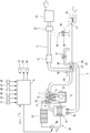
- FIG. 1 is an explanatory view showing an outline of a control device of the internal combustion engine 1.
- the internal combustion engine 1 is, for example, a spark ignition type gasoline engine, mounted on a vehicle such as a car as a drive source, and has an intake passage 2 and an exhaust passage 3.
- the intake passage 2 is connected to the combustion chamber 6 via an intake valve 4.
- the exhaust passage 3 is connected to the combustion chamber 6 via an exhaust valve 5.
- the internal combustion engine 1 has, for example, an in-cylinder direct injection type configuration, and a fuel injection valve (not shown) for injecting fuel into a cylinder and an ignition plug 7 are provided for each cylinder.
- the injection timing and injection amount of the fuel injection valve and the ignition timing of the spark plug 7 are controlled by a control signal from the control unit 8.
- the internal combustion engine 1 has, as a valve operating mechanism of the intake valve 4, an intake-side variable valve mechanism 10 capable of changing the valve timing (opening and closing timing) of the intake valve 4.
- the valve operating mechanism on the exhaust valve side is a general direct acting valve operating mechanism, and the lift operating angle of the exhaust valve 5 and the phase of the lift central angle are always constant.
- the intake-side variable valve mechanism 10 is hydraulically driven, for example, and is controlled by a control signal from the control unit 8. That is, the control unit 8 corresponds to a control unit that controls the intake-side variable valve mechanism 10.
- the control unit 8 can variably control the valve timing of the intake valve 4.
- the intake-side variable valve mechanism 10 can control the amount of air in the cylinder by controlling the closing timing of the intake valve 4. For example, when the intake valve closing timing is retarded than the bottom dead center, the air amount in the cylinder is reduced by retarding the intake valve closing timing so as to be farther than the bottom dead center. Can.
- the intake-side variable valve mechanism 10 corresponds to an air amount control unit capable of variably controlling the air amount in the cylinder.
- the intake-side variable valve mechanism 10 may be of a type in which the opening timing and closing timing of the intake valve 4 can be independently changed independently, or may be of a type in which the opening timing and closing timing are simultaneously delayed. In this embodiment, the latter type is used in which the phase of the intake camshaft 11 relative to the crankshaft 12 is retarded. Further, the intake-side variable valve mechanism 10 is not limited to one driven hydraulically, and may be electrically driven by a motor or the like.
- the valve timing of the intake valve 4 is detected by the intake side camshaft position sensor 13.
- the intake side camshaft position sensor 13 detects the phase of the intake side camshaft 11 with respect to the crankshaft 12.
- the intake passage 2 is provided with an air cleaner 16 for collecting foreign matters in intake, an air flow meter 17 for detecting the amount of intake air, and an electric throttle valve 18 capable of controlling the amount of intake air in the cylinder. There is.
- the air flow meter 17 incorporates a temperature sensor, and can detect (measure) the intake temperature of the intake port.
- the air flow meter 17 is disposed downstream of the air cleaner 16.
- the throttle valve 18 is provided with an actuator such as an electric motor, and the degree of opening thereof is controlled by a control signal from the control unit 8.
- the throttle valve 18 is disposed downstream of the air flow meter 17.
- the opening degree (throttle opening degree) of the throttle valve 18 is detected by a throttle opening degree sensor 19.
- a detection signal of the throttle opening degree sensor 19 is input to the control unit 8.
- the exhaust passage 3 is provided with an upstream exhaust catalyst 21 such as a three-way catalyst, a downstream exhaust catalyst 22 such as a three-way catalyst, and a muffler 23 for noise reduction that reduces exhaust noise.
- the downstream side exhaust catalyst 22 is disposed downstream of the upstream side exhaust catalyst 21.
- the muffler 23 is disposed downstream of the downstream side exhaust catalyst 22.
- the internal combustion engine 1 has a turbocharger 25 as a turbocharger provided coaxially with a compressor 26 provided in the intake passage 2 and a turbine 27 provided in the exhaust passage 3.
- the compressor 26 is disposed upstream of the throttle valve 18 and downstream of the air flow meter 17.
- the turbine 27 is disposed upstream of the upstream exhaust catalyst 21.
- An intake bypass passage 30 is connected to the intake passage 2.
- the intake bypass passage 30 is formed to bypass the compressor 26 and communicate the upstream side and the downstream side of the compressor 26.
- An electric recirculation valve 31 is provided in the intake bypass passage 30.
- the recirculation valve 31 is normally closed, but is opened when, for example, the throttle valve 18 is closed and the downstream side of the compressor 26 has a high pressure.
- Opening and closing of the recirculation valve 31 is controlled by a control signal from the control unit 8.
- the recirculation valve 31 is not controlled by the control unit 8 and may be a so-called check valve which opens only when the pressure on the downstream side of the compressor 26 reaches a predetermined pressure or more. It is possible.
- an intercooler 32 is provided downstream of the throttle valve 18 in the intake passage 2 for cooling the intake air compressed (pressed) by the compressor 26 to improve volumetric efficiency.
- the intercooler 32 is disposed in the intercooler cooling path (sub cooling path) 35 together with the intercooler radiator (intercooler radiator) 33 and the electric pump 34.
- the intercooler 32 can be supplied with the refrigerant (cooling water) cooled by the radiator 33.
- the intercooler cooling path 35 is configured such that the refrigerant can circulate in the path.
- the intercooler cooling path 35 is a cooling path independent of a main cooling path (not shown) in which cooling water for cooling the cylinder block 37 of the internal combustion engine 1 circulates.
- the radiator 33 cools the refrigerant in the intercooler cooling path 35 by heat exchange with the outside air.
- the electric pump 34 circulates the refrigerant in the intercooler cooling path 35 in the arrow A direction by being driven.
- the exhaust passage 3 is connected to an exhaust bypass passage 38 which bypasses the turbine 27 and connects the upstream side and the downstream side of the turbine 27.
- the downstream end of the exhaust bypass passage 38 is connected to the exhaust passage 3 at a position upstream of the upstream exhaust catalyst 21.
- a motorized waste gate valve 39 for controlling the exhaust flow rate in the exhaust bypass passage 38 is disposed.
- the internal combustion engine 1 can carry out exhaust gas recirculation (EGR) for introducing (recirculating) a part of the exhaust gas from the exhaust gas passage 3 into the intake gas passage 2 as EGR gas.
- EGR exhaust gas recirculation
- An EGR passage 41 connected to the passage 2 is provided. One end of the EGR passage 41 is connected to the exhaust passage 3 at a position between the upstream side exhaust catalyst 21 and the downstream side exhaust catalyst 22, and the other end is the downstream side of the air flow meter 17 and the upstream side of the compressor 26 Are connected to the intake passage 2.
- the EGR passage 41 is provided with an electrically operated EGR valve 42 for controlling the flow rate of the EGR gas in the EGR passage 41 and an EGR cooler 43 capable of cooling the EGR gas.
- the opening and closing operation of the EGR valve 42 is controlled by a control unit 8 as a control unit.
- the control unit 8 includes a crank angle sensor 45 capable of detecting the engine rotational speed as well as the crank angle of the crankshaft 12 in addition to the detection signals of the intake side camshaft position sensor 13, the air flow meter 17 and the throttle opening degree sensor 19 described above Detection signals from sensors such as an accelerator opening sensor 46 for detecting the depression amount of an accelerator pedal (not shown), a supercharging pressure sensor 47 for detecting supercharging pressure, and an exhaust pressure sensor 48 for detecting exhaust pressure are input. ing.
- the supercharging pressure sensor 47 is disposed in the intake passage 2 downstream of the intercooler 32, for example, a collector, and detects an intake pressure at the position.
- the exhaust pressure sensor 48 is disposed in the exhaust passage 3 upstream of the turbine 27 and detects the exhaust pressure at that position.
- the control unit 8 calculates the required load (engine load) of the internal combustion engine 1 using the detection value of the accelerator opening sensor 46.
- the control unit 8 controls the ignition timing and air-fuel ratio of the internal combustion engine 1 and controls the opening degree of the EGR valve 42 to control one of the exhaust from the exhaust passage 3 to the intake passage 2.
- the exhaust gas recirculation control (EGR control) etc. which reflux the part is implemented.
- the control unit 8 also controls the drive of the electric pump 34, the opening degree of the throttle valve 18 and the waste gate valve 39, and the like.
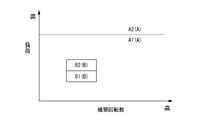
- the control unit 8 controls the air-fuel ratio of the internal combustion engine 1 according to the operating condition, using the air-fuel ratio calculation map shown in FIG. FIG. 2 is an air-fuel ratio calculation map stored in the control unit 8.
- the air-fuel ratio is allocated according to the engine load and the engine speed.
- the control unit 8 controls the air-fuel ratio to be the stoichiometric air-fuel ratio in a predetermined first operation area A, and is leaner than the first operation area A in a predetermined second operation area B on the low rotation low load side. Control is performed to achieve the air-fuel ratio. That is, the air-fuel ratio of the first operating range A corresponds to a predetermined rich air-fuel ratio, and the air-fuel ratio of the second operating range B corresponds to a predetermined lean air-fuel ratio.
- the low load side area A1 of the first operation area A is a non-supercharged area where the turbocharger 25 does not perform supercharging.
- An area A2 on the high load side of the first operation area A is a supercharging area where the turbocharger 25 performs supercharging.
- the area A1 corresponds to a second operating state in which the air-fuel ratio is richer than the air-fuel ratio in the second operating area B in the non-supercharged state.
- the low load side area B1 of the second operation area B is a non-supercharged area in which the turbocharger 25 does not perform supercharging.
- An area B2 on the high load side of the second operation area B is a supercharging area where the turbocharger 25 performs supercharging.
- the region B2 corresponds to a first operating state in which the air-fuel ratio becomes a predetermined lean air-fuel ratio in the supercharging state.
- the air-fuel ratio changes so as to be relatively rich, so the amount of air in the cylinder is controlled to decrease.
- the opening degree (throttle opening degree) of the throttle valve 18 is moved to the valve closing side so as to become the target throttle opening degree at steady state of the region A1. Fully open. However, in this case, since the supercharging pressure in the region B2 remains, the responsiveness of the exhaust pressure drop due to full opening of the waste gate valve 39 can be obtained by moving the throttle valve 18 in the valve closing direction. The responsiveness of the decrease in intake pressure may be delayed, and the intake pressure may be higher than the exhaust pressure.
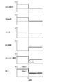
- FIG. 3 is a timing chart showing changes in various parameters at the transition time of transition of the operating state from the area B2 to the area A1 in the comparative example.
- the operating state is changed from the region B2 in which the air-fuel ratio becomes lean in the supercharged state to the region A1 in which the air-fuel ratio becomes richer than this lean air-fuel ratio in the non-supercharged state.
- the opening degree of the throttle valve 18 (throttle opening degree) is set to a predetermined amount than the target throttle opening degree at steady state of area A1 so that the intake pressure becomes lower than the exhaust pressure.
- control is performed so that the target throttle opening degree in the steady state of the region A1 is obtained.
- the amount of air in the cylinder is reduced so that the overshoot of the internal combustion engine 1 torque does not occur at the transition time when the operating state changes from area B2 to area A1.
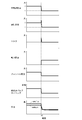
- FIG. 4 is a timing chart showing changes in various parameters at the transition time when the operating state transitions from the area B2 to the area A1 in the first embodiment.
- Closing the throttle valve 18 causes a pressure loss, which allows the intake pressure to be lower than the exhaust pressure.
- the throttle opening is closed by a predetermined amount ⁇ P smaller than the target throttle opening at steady state in region A1 to ensure intake pressure. It can be lower than the exhaust pressure.
- FIG. 5 schematically shows a calculation map of the predetermined amount ⁇ P to which the predetermined amount ⁇ P is allocated.
- the predetermined amount ⁇ P calculation map is stored in the control unit 8.
- the predetermined amount ⁇ P is set larger as the boost pressure in the region B2 is higher, and set smaller as the engine speed of the internal combustion engine in the region B2 is higher.
- the intake pressure can be sufficiently reduced, and the occurrence of the pump work can be more reliably suppressed.
- the curve rising to the right in FIG. 5 shows the relationship between the predetermined amount ⁇ P and the supercharging pressure in the region B2 when the engine rotational speeds Ne1 to Ne4 (Ne1 ⁇ Ne2 ⁇ Ne3 ⁇ Ne4) are used as parameters.
- the predetermined amount ⁇ P is set smaller as the engine speed of the internal combustion engine in the region B2 is higher.
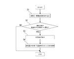
- FIG. 6 is a flow chart showing the flow of control of the internal combustion engine 1 in the first embodiment described above.
- step S1 the supercharging pressure and the engine speed are read.
- step S2 it is determined whether the driving state has transitioned from area B2 to area A1. If it is determined in step S2 that the driving state has transitioned from area B2 to area A1, the process proceeds to step S3. If it is not determined in step S2 that the driving state has transitioned from the region B2 to the region A1, the current routine is ended.
- step S3 a predetermined amount ⁇ P is calculated using the supercharging pressure and the engine speed.
- step S4 the target throttle opening degree at the transition time when the operating state transitions from the region B2 to the region A1 is corrected using the predetermined amount ⁇ P. That is, at the beginning of a transition when the operating state transitions from region B2 to region A1, throttle valve 18 is temporarily controlled to be smaller by a predetermined amount ⁇ P than the target throttle opening degree at steady state of region A1. Ru.
- the predetermined amount ⁇ P is determined according to the supercharging pressure and the engine speed, but the predetermined amount ⁇ P is calculated using only the supercharging pressure or the engine speed. You may do so.
- the amount of air in the cylinder is smaller than the amount of air for achieving a rich air-fuel ratio at the transition time when the operating state changes from region B2 to region A1.
- the air amount control unit in the second embodiment is not the throttle valve 18 but the intake-side variable valve mechanism 10.
- the closing timing of the intake valve 4 is moved so as to be the target intake valve closing timing at steady state of the region A1, and the opening degree of the throttle valve 18 (throttle opening degree) Is moved to the valve closing side so that the target throttle opening degree in the steady state of the region A1 is obtained, and the waste gate valve 39 is fully opened.
- FIG. 7 is a timing chart showing changes in various parameters during transition when the operating state transitions from area B2 to area A1 in the comparative example.
- the responsiveness of the exhaust pressure drop due to full opening of the waste gate valve 39 can be obtained by moving the throttle valve 18 in the valve closing direction.
- the responsiveness of the decrease in intake pressure may be delayed, and the intake pressure may be higher than the exhaust pressure.
- the intake valve closing timing in FIG. 7 is an example in which the target intake valve closing timing in steady state is after the intake bottom dead center in both the area A1 and the area B2.
- the operating state transitions from the region B2 in which the air-fuel ratio becomes lean in the supercharged state to the region A1 in which the air-fuel ratio becomes richer than this lean air-fuel ratio in the non-supercharged state.
- the intake valve closing timing is controlled so as to be temporarily away from the bottom dead center by a predetermined amount ⁇ Q further than the intake valve closing timing in steady state of region A1, steady state in region A1 Control is performed so that the intake valve closing timing is reached.
- the intake-side variable valve mechanism 10 moves away from the bottom dead center more than the target intake valve closing time at steady state in area A1.
- the valve timing of the intake valve 4 is temporarily advanced or retarded.
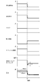
- FIG. 8 is a timing chart showing changes in various parameters at the transition time when the operating state transitions from area B2 to area A1 in the second embodiment.
- the intake-side variable valve mechanism 10 operates during transition when the operating state transitions from the region B2 to the region A1.
- the valve timing of the intake valve 4 is controlled so that the intake valve closing timing temporarily advances further than the target intake valve closing timing at the steady state of the region A1.
- the amount of air in the cylinder is reduced so that the torque overshoot does not occur in the internal combustion engine 1 at the transition time when the operating state changes from the region B2 to the region A1.
- the intake valve closing timing in FIG. 8 is an example in which the target intake valve closing timing in the steady state is after the intake bottom dead center in both the area A1 and the area B2.
- the intake valve closing timing is controlled so as to temporarily move away from the bottom dead center by a predetermined amount ⁇ Q further than the intake valve closing timing at steady state in region A1.
- FIG. 9 schematically shows a calculation map of the predetermined amount ⁇ Q to which the predetermined amount ⁇ Q is allocated.
- the predetermined amount ⁇ Q calculation map is stored in the control unit 8.
- the predetermined amount ⁇ Q is set larger as the supercharging pressure in the region B2 is higher, and set smaller as the engine speed of the internal combustion engine in the region B2 is higher.
- the curve rising to the right in FIG. 9 shows the relationship between the predetermined amount ⁇ Q and the supercharging pressure in the region B2 when the engine rotational speeds Ne1 to Ne4 (Ne1 ⁇ Ne2 ⁇ Ne3 ⁇ Ne4) are used as parameters.
- the intake pressure can be sufficiently reduced, and the occurrence of the pump work can be more reliably suppressed.
- the predetermined amount ⁇ Q can be set smaller as the engine speed of the internal combustion engine in the region B2 becomes higher.
- FIG. 10 is a flowchart showing the flow of control of the internal combustion engine 1 in the second embodiment described above.
- step S11 the supercharging pressure and the engine speed are read.
- step S12 it is determined whether the driving state has transitioned from area B2 to area A1. If it is determined in step S12 that the driving state has transitioned from area B2 to area A1, the process proceeds to step S13. If it is not determined in step S12 that the driving state has transitioned from the area B2 to the area A1, the current routine is ended.
- step S13 a predetermined amount ⁇ Q is calculated using the supercharging pressure and the engine speed.
- step S14 the intake-side variable valve mechanism 10 is controlled at the transition time when the operating state transitions from the region B2 to the region A1 using the predetermined amount ⁇ Q. That is, at the beginning of the transition when the operating state transitions from region B2 to region A1, the intake variable valve mechanism 10 temporarily reduces the intake valve closing timing to a point lower than the intake valve closing timing at the steady state of the region A1. Control is performed so as to move away from the intake bottom dead center by a fixed amount ⁇ Q.
- the predetermined amount ⁇ Q is determined according to the supercharging pressure and the engine speed, but the predetermined amount ⁇ Q is calculated using only the supercharging pressure or the engine speed. You may do so.
- each embodiment mentioned above relates to the control method and control device of the internal combustion engine 1.
Landscapes
- Engineering & Computer Science (AREA)
- Chemical & Material Sciences (AREA)
- Combustion & Propulsion (AREA)
- Mechanical Engineering (AREA)
- General Engineering & Computer Science (AREA)
- Output Control And Ontrol Of Special Type Engine (AREA)
- Electrical Control Of Air Or Fuel Supplied To Internal-Combustion Engine (AREA)
- Control Of Throttle Valves Provided In The Intake System Or In The Exhaust System (AREA)
- Combined Controls Of Internal Combustion Engines (AREA)
Priority Applications (5)
| Application Number | Priority Date | Filing Date | Title |
|---|---|---|---|
| JP2019567422A JP6923005B2 (ja) | 2018-01-23 | 2018-01-23 | 内燃機関の制御方法及び内燃機関の制御装置 |
| PCT/JP2018/001877 WO2019145991A1 (ja) | 2018-01-23 | 2018-01-23 | 内燃機関の制御方法及び内燃機関の制御装置 |
| EP18902085.2A EP3744962A4 (de) | 2018-01-23 | 2018-01-23 | Verbrennungsmotorsteuerungsverfahren und verbrennungsmotorsteuerungsvorrichtung |
| CN201880087198.8A CN111630264B (zh) | 2018-01-23 | 2018-01-23 | 内燃机的控制方法以及内燃机的控制装置 |
| US16/963,571 US11441497B2 (en) | 2018-01-23 | 2018-01-23 | Internal combustion engine control method and internal combustion engine control device |
Applications Claiming Priority (1)
| Application Number | Priority Date | Filing Date | Title |
|---|---|---|---|
| PCT/JP2018/001877 WO2019145991A1 (ja) | 2018-01-23 | 2018-01-23 | 内燃機関の制御方法及び内燃機関の制御装置 |
Publications (1)
| Publication Number | Publication Date |
|---|---|
| WO2019145991A1 true WO2019145991A1 (ja) | 2019-08-01 |
Family
ID=67396015
Family Applications (1)
| Application Number | Title | Priority Date | Filing Date |
|---|---|---|---|
| PCT/JP2018/001877 WO2019145991A1 (ja) | 2018-01-23 | 2018-01-23 | 内燃機関の制御方法及び内燃機関の制御装置 |
Country Status (5)
| Country | Link |
|---|---|
| US (1) | US11441497B2 (de) |
| EP (1) | EP3744962A4 (de) |
| JP (1) | JP6923005B2 (de) |
| CN (1) | CN111630264B (de) |
| WO (1) | WO2019145991A1 (de) |
Citations (3)
| Publication number | Priority date | Publication date | Assignee | Title |
|---|---|---|---|---|
| JP2006016973A (ja) | 2004-06-30 | 2006-01-19 | Mazda Motor Corp | 筒内噴射式内燃機関の制御装置 |
| JP2015151972A (ja) * | 2014-02-18 | 2015-08-24 | トヨタ自動車株式会社 | 制御装置 |
| JP2017077813A (ja) * | 2015-10-21 | 2017-04-27 | トヨタ自動車株式会社 | 車両の制御装置 |
Family Cites Families (29)
| Publication number | Priority date | Publication date | Assignee | Title |
|---|---|---|---|---|
| JP3508481B2 (ja) * | 1997-07-08 | 2004-03-22 | 日産自動車株式会社 | 内燃機関の制御装置 |
| FR2784944B1 (fr) * | 1998-10-23 | 2000-12-15 | Renault | Groupe motopropulseur hybride |
| US6470869B1 (en) * | 1999-10-18 | 2002-10-29 | Ford Global Technologies, Inc. | Direct injection variable valve timing engine control system and method |
| JP3926522B2 (ja) * | 1999-09-20 | 2007-06-06 | 株式会社日立製作所 | 過給機付エンジンの吸気制御装置 |
| JP2004060479A (ja) * | 2002-07-26 | 2004-02-26 | Hitachi Ltd | エンジンの燃料制御装置,エンジンの燃料制御方法 |
| JP4577656B2 (ja) * | 2006-02-15 | 2010-11-10 | 株式会社デンソー | 過給機付き内燃機関の制御装置 |
| JP4375387B2 (ja) * | 2006-11-10 | 2009-12-02 | トヨタ自動車株式会社 | 内燃機関 |
| JP4799455B2 (ja) * | 2007-03-22 | 2011-10-26 | 本田技研工業株式会社 | 内燃機関の制御装置 |
| JP2007263127A (ja) * | 2007-07-23 | 2007-10-11 | Hitachi Ltd | エンジンの燃料制御装置,エンジンの燃料制御方法 |
| JP2011112032A (ja) * | 2009-11-30 | 2011-06-09 | Isuzu Motors Ltd | 内燃機関の制御方法および内燃機関 |
| US20140224227A1 (en) * | 2011-07-05 | 2014-08-14 | Toyota Jidosha Kabushiki Kaisha | Control unit of internal combustion engine equipped with supercharger |
| JP5708820B2 (ja) * | 2011-11-01 | 2015-04-30 | 日産自動車株式会社 | 内燃機関の制御装置及び制御方法 |
| JP6041050B2 (ja) * | 2013-05-14 | 2016-12-07 | トヨタ自動車株式会社 | 内燃機関の制御装置 |
| DE112013007145B4 (de) * | 2013-06-06 | 2018-09-13 | Toyota Jidosha Kabushiki Kaisha | Steuervorrichtung für mit Turbolader ausgerüstetem Verbrennungsmotor |
| WO2014199443A1 (ja) * | 2013-06-11 | 2014-12-18 | トヨタ自動車株式会社 | 内燃機関の制御装置 |
| JP5983882B2 (ja) * | 2013-07-09 | 2016-09-06 | トヨタ自動車株式会社 | 内燃機関の制御装置 |
| JP5967064B2 (ja) * | 2013-12-13 | 2016-08-10 | トヨタ自動車株式会社 | 内燃機関の制御装置 |
| JP6090238B2 (ja) * | 2014-06-05 | 2017-03-08 | トヨタ自動車株式会社 | 車両の制御装置 |
| JP5979180B2 (ja) * | 2014-06-17 | 2016-08-24 | トヨタ自動車株式会社 | 車両制御装置 |
| US9677510B2 (en) * | 2014-10-14 | 2017-06-13 | Ford Global Technologies, Llc | Systems and methods for transient control |
| JP6287802B2 (ja) * | 2014-12-12 | 2018-03-07 | トヨタ自動車株式会社 | 内燃機関の制御装置 |
| JP6241412B2 (ja) * | 2014-12-25 | 2017-12-06 | トヨタ自動車株式会社 | 内燃機関の制御装置 |
| JP6213507B2 (ja) * | 2015-03-19 | 2017-10-18 | トヨタ自動車株式会社 | 内燃機関の制御装置 |
| JP6222193B2 (ja) * | 2015-09-15 | 2017-11-01 | トヨタ自動車株式会社 | 内燃機関の制御装置 |
| JP6414143B2 (ja) * | 2016-06-16 | 2018-10-31 | トヨタ自動車株式会社 | 内燃機関の制御装置 |
| JP6550110B2 (ja) * | 2017-09-28 | 2019-07-24 | 株式会社Subaru | エンジン制御装置 |
| JP6852802B2 (ja) * | 2017-10-12 | 2021-03-31 | 日産自動車株式会社 | ハイブリッド車両の制御方法および制御装置 |
| US11187166B2 (en) * | 2017-12-22 | 2021-11-30 | Nissan Motor Co., Ltd. | Internal combustion engine and method of controlling same |
| JP6973111B2 (ja) * | 2018-01-23 | 2021-11-24 | マツダ株式会社 | エンジンの制御方法及びエンジンシステム |
-
2018
- 2018-01-23 WO PCT/JP2018/001877 patent/WO2019145991A1/ja unknown
- 2018-01-23 US US16/963,571 patent/US11441497B2/en active Active
- 2018-01-23 EP EP18902085.2A patent/EP3744962A4/de active Pending
- 2018-01-23 CN CN201880087198.8A patent/CN111630264B/zh active Active
- 2018-01-23 JP JP2019567422A patent/JP6923005B2/ja active Active
Patent Citations (3)
| Publication number | Priority date | Publication date | Assignee | Title |
|---|---|---|---|---|
| JP2006016973A (ja) | 2004-06-30 | 2006-01-19 | Mazda Motor Corp | 筒内噴射式内燃機関の制御装置 |
| JP2015151972A (ja) * | 2014-02-18 | 2015-08-24 | トヨタ自動車株式会社 | 制御装置 |
| JP2017077813A (ja) * | 2015-10-21 | 2017-04-27 | トヨタ自動車株式会社 | 車両の制御装置 |
Non-Patent Citations (1)
| Title |
|---|
| See also references of EP3744962A4 |
Also Published As
| Publication number | Publication date |
|---|---|
| EP3744962A4 (de) | 2021-01-20 |
| CN111630264B (zh) | 2022-12-30 |
| JP6923005B2 (ja) | 2021-08-18 |
| US20210054794A1 (en) | 2021-02-25 |
| JPWO2019145991A1 (ja) | 2020-12-17 |
| EP3744962A1 (de) | 2020-12-02 |
| US11441497B2 (en) | 2022-09-13 |
| CN111630264A (zh) | 2020-09-04 |
Similar Documents
| Publication | Publication Date | Title |
|---|---|---|
| JP4623064B2 (ja) | 過給機付き内燃機関の制御装置 | |
| JP5825994B2 (ja) | 内燃機関の制御装置 | |
| EP1848885B1 (de) | Steuerverfahren und steuervorrichtung für verbrennungsmotor | |
| JP5278600B2 (ja) | 内燃機関の燃焼制御装置 | |
| JP2009024599A (ja) | 内燃機関の制御装置 | |
| JP5092962B2 (ja) | 過給機付き内燃機関の制御装置 | |
| EP3730770B1 (de) | Brennkraftmaschine und verfahren zur steuerung davon | |
| JP4893514B2 (ja) | 過給機付き内燃機関の制御装置 | |
| CN108730052B (zh) | 内燃机的控制装置 | |
| JP2013130121A (ja) | 火花点火式内燃機関の排気還流装置 | |
| JP2009299623A (ja) | 内燃機関の制御装置 | |
| US20180030884A1 (en) | Control device of internal combustion engine | |
| WO2019145991A1 (ja) | 内燃機関の制御方法及び内燃機関の制御装置 | |
| JPS6093137A (ja) | 過給機付内燃機関 | |
| JP2018131924A (ja) | 内燃機関の制御方法及び内燃機関の制御装置 | |
| JP2673427B2 (ja) | 過給機付エンジン | |
| JP5333678B2 (ja) | エンジンの制御装置 | |
| JP2007016682A (ja) | 圧縮自己着火内燃機関の制御装置 | |
| US20190226412A1 (en) | Control device for internal combustion engine | |
| JP6191311B2 (ja) | エンジンの制御装置 | |
| JP2019120215A (ja) | 内燃機関の制御方法及び内燃機関の制御装置 | |
| WO2011141998A1 (ja) | 内燃機関の制御装置 | |
| JPS60116822A (ja) | 内燃機関の吸気弁作動装置 | |
| JP2005226492A (ja) | ターボチャージャを備えた内燃機関 |
Legal Events
| Date | Code | Title | Description |
|---|---|---|---|
| 121 | Ep: the epo has been informed by wipo that ep was designated in this application |
Ref document number: 18902085 Country of ref document: EP Kind code of ref document: A1 |
|
| ENP | Entry into the national phase |
Ref document number: 2019567422 Country of ref document: JP Kind code of ref document: A |
|
| NENP | Non-entry into the national phase |
Ref country code: DE |
|
| ENP | Entry into the national phase |
Ref document number: 2018902085 Country of ref document: EP Effective date: 20200824 |