WO2019142240A1 - 浴室乾燥機 - Google Patents
浴室乾燥機 Download PDFInfo
- Publication number
- WO2019142240A1 WO2019142240A1 PCT/JP2018/001049 JP2018001049W WO2019142240A1 WO 2019142240 A1 WO2019142240 A1 WO 2019142240A1 JP 2018001049 W JP2018001049 W JP 2018001049W WO 2019142240 A1 WO2019142240 A1 WO 2019142240A1
- Authority
- WO
- WIPO (PCT)
- Prior art keywords
- net
- bathroom
- filter
- suction port
- filter unit
- Prior art date
- Legal status (The legal status is an assumption and is not a legal conclusion. Google has not performed a legal analysis and makes no representation as to the accuracy of the status listed.)
- Ceased
Links
Images


Classifications
-
- D—TEXTILES; PAPER
- D06—TREATMENT OF TEXTILES OR THE LIKE; LAUNDERING; FLEXIBLE MATERIALS NOT OTHERWISE PROVIDED FOR
- D06F—LAUNDERING, DRYING, IRONING, PRESSING OR FOLDING TEXTILE ARTICLES
- D06F58/00—Domestic laundry dryers
- D06F58/10—Drying cabinets or drying chambers having heating or ventilating means
-
- B—PERFORMING OPERATIONS; TRANSPORTING
- B01—PHYSICAL OR CHEMICAL PROCESSES OR APPARATUS IN GENERAL
- B01D—SEPARATION
- B01D53/00—Separation of gases or vapours; Recovering vapours of volatile solvents from gases; Chemical or biological purification of waste gases, e.g. engine exhaust gases, smoke, fumes, flue gases, aerosols
- B01D53/26—Drying gases or vapours
-
- F—MECHANICAL ENGINEERING; LIGHTING; HEATING; WEAPONS; BLASTING
- F24—HEATING; RANGES; VENTILATING
- F24F—AIR-CONDITIONING; AIR-HUMIDIFICATION; VENTILATION; USE OF AIR CURRENTS FOR SCREENING
- F24F13/00—Details common to, or for air-conditioning, air-humidification, ventilation or use of air currents for screening
- F24F13/28—Arrangement or mounting of filters
-
- F—MECHANICAL ENGINEERING; LIGHTING; HEATING; WEAPONS; BLASTING
- F26—DRYING
- F26B—DRYING SOLID MATERIALS OR OBJECTS BY REMOVING LIQUID THEREFROM
- F26B9/00—Machines or apparatus for drying solid materials or objects at rest or with only local agitation; Domestic airing cupboards
- F26B9/02—Machines or apparatus for drying solid materials or objects at rest or with only local agitation; Domestic airing cupboards in buildings
Definitions
- the present invention relates to a bathroom dryer which circulates air taken into the bathroom from inside the bathroom and discharges air taken from the inside of the bathroom out of the bathroom.
- a bathroom drier is provided with a circulation port through which a circulating air flow for circulating air taken in from inside the bathroom into the bathroom and an exhaust port through which an exhaust flow through which air taken in from the bathroom is discharged out of the bathroom passes
- the bathroom dryer performs heating operation to warm air from inside the bathroom with a heater and send warm air to the circulation port, ventilation operation to send air from inside the bathroom to the exhaust port, and send air from inside the bathroom to the exhaust port At the same time, perform a drying operation to send warm air or cool air to the circulation port.
- a filter unit for removing dust, which flows with the air flow, from the air flow is detachably attached to a suction port through which the air flow taken in from the bathroom passes, of the bathroom dryer.
- Patent Document 1 discloses a bathroom dryer including a removable filter unit.
- the filter portion is provided with a net through which air flows and a grid portion forming a grid that divides the net. Dust attached to the filter section is removed by cleaning.
- the regular cleaning of the filter unit suppresses the decrease in air volume due to the clogging of the filter unit.
- Patent No. 5460921 gazette
- the net may be broken due to an external force received each time cleaning. Net breaks may also occur inside the grid when the filter is manufactured.
- This invention is made in view of the above, Comprising: It aims at obtaining the bathroom drier which makes it possible to reduce the fracture
- the bathroom dryer according to the present invention includes a blower, a case in which the blower is housed, and an air flow sucked into the case from inside the bathroom by the operation of the blower. And a panel disposed inside the bathroom of the main body, and a filter that is detachably attached to the panel and covers the suction port.
- the filter portion has a net through which the air flow passes, and a grid portion which divides the surface of the net in a grid and has the net fixed.
- the lattice portion includes a first portion erected from the surface of the net, and a second portion projecting lower than the first portion at a height in a direction perpendicular to the surface of the net from the first portion. Have.
- the bathroom dryer according to the present invention has the effect of being able to reduce the breakage of the net in the filter section.
- the figure which shows the structure of the bathroom dryer concerning Embodiment 1 of this invention The perspective view which shows the base and panel which the bathroom dryer shown in FIG. 1 has The figure which shows the filter part which the bathroom dryer shown in FIG. 1 has Sectional view of the filter part in the IV-IV line shown in FIG. 3
- FIG. 1 is a diagram showing a configuration of a bathroom dryer 100 according to Embodiment 1 of the present invention.
- the bathroom dryer 100 is installed on the ceiling of the bathroom.
- the bathroom dryer 100 is connected to a duct disposed to connect the ceiling to the outside of the bathroom. In FIG. 1, illustration of the ceiling and the duct is omitted.
- the bathroom dryer 100 may be installed on a bathroom wall or window.
- the bathroom dryer 100 includes a main body 1, a sirocco fan 2 which is a blower, and a panel 5 disposed inside the bathroom of the main body 1.
- the main body portion 1 has a case 3 which is a box body in which the sirocco fan 2 is stored, and a base 4 provided inside the bathroom of the case 3.
- the main body 1 is composed of a case 3, the components housed in the case 3, and a base 4.
- a fan motor 9 as a driving source of the sirocco fan 2 and a damper 12 described later are housed in a case 3.
- the sirocco fan 2 receives the driving force of the fan motor 9 and rotates to generate an air flow.
- the base 4 is provided with a suction port 6 through which an air flow sucked into the case 3 from inside the bathroom by the operation of the sirocco fan 2 passes. Further, the base 4 is provided with a circulation port 7 through which a circulating air flow for circulating the air taken in from the inside of the bathroom into the inside of the bathroom.
- the side 3a of the case 3 is provided with an exhaust port 8 through which an exhaust flow for discharging the air taken in from inside the bathroom to the outside of the bathroom passes.
- the exhaust port 8 is connected to the duct.
- the case 3 is inserted into the ceiling through the opening provided in the ceiling, and the case 3 is disposed in the ceiling.
- the main body 1 is installed on the ceiling in a state where the suction port 6 and the circulation port 7 are directed downward in the bathroom.
- the panel 5 covers the lower side of the base 4.
- the surface directed downward in the panel 5 is a design surface on which a design is given.
- a first air passage 13 for advancing the air flow from the sirocco fan 2 to the circulation port 7 and a second air passage 14 for advancing the air flow from the sirocco fan 2 to the exhaust port 8 are provided.
- the damper 12 is disposed at a branch of the first air passage 13 and the second air passage 14.
- the damper 12 adjusts the opening degree of the first air passage 13 and the opening degree of the second air passage 14 by rotational driving.
- the heater 11 is installed above the circulation port 7. The heater 11 heats the air advancing toward the circulation port 7.
- the bathroom dryer 100 heats the air from inside the bathroom with the heater 11 and blows out warm air from the circulation port 7 and the ventilation operation to discharge the air from inside the bathroom from the exhaust port 8 to the outside of the bathroom, and the bathroom At the same time as discharging air from the inside from the exhaust port 8, a drying operation is performed in which warm air or cool air is blown from the circulation port 7.
- the bathroom dryer 100 drives the damper 12 to switch between the heating operation, the ventilation operation, and the drying operation.
- FIG. 2 is a perspective view showing a base 4 and a panel 5 which the bathroom dryer 100 shown in FIG. 1 has.
- FIG. 2 shows the base 4 and the panel 5 provided below the base 4 as viewed from below.
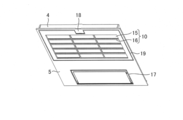
- an opening 17 through which the circulation air flow from the circulation port 7 to the bathroom passes is provided.
- the circulating air flow from the first air passage 13 travels into the bathroom through the circulation port 7 and the opening 17.
- the bathroom dryer 100 includes a filter unit 10 that is detachably attached to the panel 5 and covers the suction port 6.
- the filter unit 10 is fitted into the opening 19 provided in the panel 5.
- the filter unit 10 has a net 15 through which the air flow passes, and a grid portion 16 which divides the surface of the net 15 into a grid and the net 15 is fixed.
- the air flow advancing from the inside of the bathroom to the suction port 6 passes through the net 15 of the filter unit 10 attached to the panel 5.
- the filter unit 10 collects the dust flowing with the air flow by the net 15 and removes the dust from the air flow taken into the case 3.
- the bathroom dryer 100 can reduce dust entering the case 3.
- FIG. 3 is a figure which shows the filter part 10 which the bathroom dryer 100 shown in FIG. 1 has.
- the filter unit 10 has a filter frame 20 which is an outer edge portion of the filter unit 10.
- the grid portion 16 is provided in the area surrounded by the filter frame 20.
- the lattice portion 16 includes straight vertical line portions 23 and horizontal line portions 24 orthogonal to each other.
- the vertical line portions 23 are parallel to each other.
- the horizontal line portions 24 are parallel to each other.
- the net 15 is partitioned by a plurality of vertical line portions 23 and a plurality of horizontal line portions 24.
- the number of vertical line portions 23 and horizontal line portions 24 is not limited to the number shown in FIG. 3 and is arbitrary.
- the net 15 is formed of a thin resin material forming a mesh capable of filtering dust from an air flow.
- the material of the net 15 may be a material other than resin.
- Resin is used for the material of the lattice portion 16.
- the filter frame 20 encloses the net 15 and the grid portion 16.
- the first end 26 of the filter frame 20 is provided with two hinges 21 that can be engaged with the edge of the opening 19 of the panel 5.
- a rectangular recess 25 is provided at the second end 27 of the filter frame 20 opposite to the first end 26, a rectangular recess 25 is provided at the second end 27 of the filter frame 20 opposite to the first end 26, a rectangular recess 25 is provided at the second end 27 of the filter frame 20 opposite to the first end 26, a rectangular recess 25 is provided at the second end 27 of the filter frame 20 opposite to the first end 26, a rectangular recess 25 is provided.
- the recess portion 25 is provided with a claw portion 22.
- the claw portion 22 can be engaged with a leaf spring-like claw receiving portion 18 provided on the panel 5. In the state where the filter portion 10 is attached to the panel 5, the hinge portion 21 is engaged with the opening 19, and the claw portion 22 is engaged with the claw receiving portion 18.
- the number of hinges 21 is not limited to two and is arbitrary.
- the hook receiving unit 18 In the state where the filter unit 10 is attached to the panel 5, the hook receiving unit 18 is pressed from below, so that the engagement between the hook unit 22 and the hook receiving unit 18 is released.
- the finger pushing the claw receiving portion 18 is hung on the recess 25 and the portion on the second end 27 side of the filter portion 10 is pulled downward, so that the filter portion 10 rotates around the first end 26. .
- the hinge 21 By the rotation of the hinge 21 with respect to the panel 5, the hinge 21 can be released from being engaged with the opening 19.
- the filter unit 10 By pulling the filter unit 10 after rotating the filter unit 10, the engagement with the opening 19 of the hinge unit 21 is released. Thereby, the filter unit 10 is removed from the panel 5.
- the filter unit 10 removed from the panel 5 is attached to the panel 5 in the reverse procedure to the removal from the panel 5.
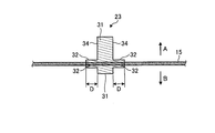
- FIG. 4 is a cross-sectional view of the filter portion 10 taken along line IV-IV shown in FIG.
- the cross section shown in FIG. 4 is a cross section including one vertical line portion 23.
- the vertical line portions 23 and the horizontal line portions 24 provided in the filter portion 10 have the same cross-sectional configuration as the cross-sectional configuration shown in FIG. 4.
- Arrow A shown in FIG. 4 represents upward in the direction from the filter portion 10 to the suction port 6.
- Arrow B shown in FIG. 4 indicates downward.
- the vertical line portion 23 has a first portion 31 vertically erected from the surface of the net 15 and a height in the direction perpendicular to the surface of the net 15 lower than that of the first portion 31. And a second portion 32 projecting along the The first portion 31 is erected on the side of the suction port 6 with respect to the net 15 and on the side opposite to the side of the suction port 6 with respect to the net 15.
- the second portion 32 is provided on the side of the suction port 6 with respect to the net 15 and on the side opposite to the side of the suction port 6 with respect to the net 15.
- the grid portion 16 includes the net 15 by the portion of the first portion 31 and the second portion 32 on the side of the suction port 6 with respect to the net 15 and the portion on the side opposite to the side of the suction port 6 with respect to the net 15 Hold it.
- the first portion 31 is provided so as to project vertically upward and downward from the net 15.
- the first portion 31 is formed such that the upward protrusion from the net 15 is larger than the downward protrusion from the net 15.
- the upward and downward protrusion of the second portion 32 is smaller than that of the first portion 31.
- the second portion 32 protrudes from the first portion 31 so as to form a ridge on the upper side and the lower side of the net 15.
- the thickness of the portion of the second portion 32 above the net 15 in the vertical direction and the thickness of the portion of the second portion 32 below the net 15 are the same.
- the net 15 is fixed by being sandwiched between a portion above the net 15 of the first portion 31 and the second portion 32, and a portion below the net 15 of the first portion 31 and the second portion 32. There is.
- since the second portion 32 is provided in the lattice portion 16, compared with the case where the lattice portion 16 is configured to have only the first portion 31, The width of the fixed part is expanded.
- an external force such as a force caused by a tool such as a vacuum cleaner or a brush or a water pressure in washing with water is applied to the filter unit 10.
- the filter section 10 can reduce breakage of the net 15 when an external force is applied to the net 15 because the width of the fixed portion between the net 15 and the lattice section 16 is expanded by the second portion 32. Also, the net 15 is held by the first portion 31 and the second portion 32 from both the upper side and the lower side.
- the filter unit 10 can reduce breakage of the net 15 even when an external force is applied to the net 15 from either of the upper and lower sides.
- the length D shown in FIG. 4 is the length of the second portion 32 from the side surface 34 of the first portion 31 to the end of the second portion 32 opposite to the side of the first portion 31.
- the length D is 0.5 mm or more and 5 mm or less.
- the filter unit 10 can be configured to withstand an external force applied in cleaning.
- the bathroom dryer 100 can suppress an increase in pressure loss due to the air flow being blocked by the filter unit 10.
- the bathroom dryer 100 can suppress the decrease in air blowing performance by suppressing the increase in pressure loss. Since the filter portion 10 has the length D of 0.5 mm or more and 5 mm or less, it is possible to reduce the breakage of the net 15 and to suppress the deterioration of the air blowing performance.
- the filter frame 20 shown in FIG. 3 has a third portion 33 in which the net 15 is fixed in the same cross-sectional shape as the second portion 32. The entire outer edge of the net 15 is fixed to the third portion 33.
- the resin is allowed to flow into the gap between the molded part and the net 15 in a state where the net 15 is sandwiched by the molded parts of the resin constituting the filter frame 20 and the grid part 16
- the net 15 is fixed to the grid portion 16 and the filter frame 20 by solidifying.
- the filter portion 10 can strengthen the fixation of the net 15 in the lattice portion 16 by reducing the breakage of the net 15 at the second portion 32.
- the filter unit 10 can reduce the breakage of the net 15 caused by the breakage of the net 15 in the lattice unit 16 spreading to the outside of the lattice unit 16. Even when the breakage of the net 15 at the first portion 31 occurs, the filter portion 10 can reduce the breakage of the net 15 caused by the breakage in the first portion 31 spreading to the outside of the lattice portion 16.
- the third portion 33 is provided on the filter frame 20, so that the width of the fixing portion between the net 15 and the filter frame 20 is expanded, so that an external force is applied to the net 15 Fracture of the net 15 can be reduced. Further, similarly to the second portion 32, the flow rate of the resin can be reduced also in the third portion 33.
- the filter unit 10 can reduce breakage of the net 15 at the third portion 33.
- the filter unit 10 can strengthen the fixation of the net 15 on the filter frame 20 by reducing the breakage of the net 15 at the third portion 33.
- the filter unit 10 can reduce the breakage of the net 15 caused by the breakage of the net 15 in the filter frame 20 spreading to the outside of the filter frame 20.
- the cross-sectional shapes of the vertical line portion 23 and the horizontal line portion 24 may be different from the cross-sectional shape shown in FIG. 4.
- the size of the protrusion on the upper side and the lower side of the net 15 may be the same.
- the second portion 32 may be provided only on one of the upper side and the lower side of the net 15. Even when the second portion 32 is provided on one of the upper side and the lower side of the net 15, the filter unit 10 can obtain an effect that breakage of the net 15 can be reduced.
- the second portion 32 protruding from the first portion 31 along the net 15 is provided in the filter portion 10, so that the net 15 in the filter portion 10 is broken. The effect of being able to reduce is produced.
- the configuration shown in the above embodiment shows an example of the contents of the present invention, and can be combined with another known technique, and one of the configurations is possible within the scope of the present invention. Parts can be omitted or changed.
Landscapes
- Engineering & Computer Science (AREA)
- Chemical & Material Sciences (AREA)
- Textile Engineering (AREA)
- Mechanical Engineering (AREA)
- General Engineering & Computer Science (AREA)
- Analytical Chemistry (AREA)
- General Chemical & Material Sciences (AREA)
- Oil, Petroleum & Natural Gas (AREA)
- Chemical Kinetics & Catalysis (AREA)
- Combustion & Propulsion (AREA)
- Drying Of Solid Materials (AREA)
- Ventilation (AREA)
Abstract
浴室乾燥機は、送風機と、送風機が収納されているケースと、送風機の動作により浴室内からケースへ吸い込まれる空気流が通過する吸込口とを有する本体部と、本体部の浴室内側に配置されているパネルと、パネルに着脱可能に取り付けられて吸込口を被覆するフィルター部(10)とを備える。フィルター部(10)は、空気流が通過するネット(15)と、ネット(15)の表面を格子状に仕切るとともにネット(15)が固定されている格子部(16)とを有する。格子部(16)は、ネット(15)の表面から立てられている第1部位と、ネット(15)の表面に垂直な方向における高さが第1部位より低くされて第1部位からネット(15)に沿って突出している第2部位とを有する。
Description
本発明は、浴室内から取り込まれた空気の浴室への循環と、浴室内から取り込まれた空気の浴室の外への排出とを行う浴室乾燥機に関する。
浴室内から取り込まれた空気を浴室内へ循環させる循環気流が通過する循環口と、浴室内から取り込まれた空気を浴室の外へ排出させる排気流が通過する排気口とを備える浴室乾燥機が知られている。浴室乾燥機は、浴室内からの空気をヒーターで暖めて循環口へ温風を送る暖房運転と、浴室内からの空気を排気口へ送る換気運転と、浴室内からの空気を排気口へ送ると同時に循環口へ温風または涼風を送る乾燥運転とを行う。浴室乾燥機のうち、浴室内から取り込まれる空気流が通過する吸込口には、空気流とともに流動する塵埃を空気流から取り除くためのフィルター部が着脱可能に取り付けられる。
特許文献1には、着脱可能なフィルター部を備える浴室乾燥機が開示されている。フィルター部には、一般に、空気流を通すネットと、ネットを仕切る格子をなす格子部とが設けられている。フィルター部に付着した塵埃は、清掃により取り除かれる。浴室乾燥機は、フィルター部の定期的な清掃により、フィルター部の目詰まりによる風量の低下が抑えられる。
フィルター部は、清掃のたびに受ける外力により、ネットが破断することがあり得る。ネットの破断は、フィルターが製造されるときに格子部の内部にて生じることもある。
本発明は、上記に鑑みてなされたものであって、フィルター部におけるネットの破断を低減可能とする浴室乾燥機を得ることを目的とする。
上述した課題を解決し、目的を達成するために、本発明にかかる浴室乾燥機は、送風機と、送風機が収納されているケースと、送風機の動作により浴室内からケースへ吸い込まれる空気流が通過する吸込口とを有する本体部と、本体部の浴室内側に配置されているパネルと、パネルに着脱可能に取り付けられて吸込口を被覆するフィルター部とを備える。フィルター部は、空気流が通過するネットと、ネットの表面を格子状に仕切るとともにネットが固定されている格子部とを有する。格子部は、ネットの表面から立てられている第1部位と、ネットの表面に垂直な方向における高さが第1部位より低くされて第1部位からネットに沿って突出している第2部位とを有する。
本発明にかかる浴室乾燥機は、フィルター部におけるネットの破断を低減できるという効果を奏する。
以下に、本発明の実施の形態にかかる浴室乾燥機を図面に基づいて詳細に説明する。なお、この実施の形態によりこの発明が限定されるものではない。
実施の形態1.
図1は、本発明の実施の形態1にかかる浴室乾燥機100の構成を示す図である。浴室乾燥機100は、浴室の天井に設置される。浴室乾燥機100は、天井裏と浴室の外とを繋いで配設されたダクトに接続される。図1では、天井とダクトとの図示を省略している。浴室乾燥機100は、浴室の壁または窓に設置されるものであっても良い。
図1は、本発明の実施の形態1にかかる浴室乾燥機100の構成を示す図である。浴室乾燥機100は、浴室の天井に設置される。浴室乾燥機100は、天井裏と浴室の外とを繋いで配設されたダクトに接続される。図1では、天井とダクトとの図示を省略している。浴室乾燥機100は、浴室の壁または窓に設置されるものであっても良い。
浴室乾燥機100は、本体部1と、送風機であるシロッコファン2と、本体部1の浴室内側に配置されているパネル5とを備える。本体部1は、シロッコファン2が収納されている箱体であるケース3と、ケース3の浴室内側に設けられたベース4とを有する。
本体部1は、ケース3と、ケース3に収納されている構成要素と、ベース4とにより構成されている。なお、図1には、ケース3に収納されている主な構成要素を模式的に示すとともに、ベース4およびパネル5の側面構成を示している。シロッコファン2の駆動源であるファンモーター9と、後述のダンパー12は、ケース3に収納されている。
シロッコファン2は、ファンモーター9の駆動力を受けて回転して、空気流を発生させる。ベース4には、シロッコファン2の動作によって浴室内からケース3へ吸い込まれる空気流が通過する吸込口6が設けられている。また、ベース4には、浴室内から取り込まれた空気を浴室内へ循環させる循環気流が通過する循環口7が設けられている。ケース3の側面3aには、浴室内から取り込まれた空気を浴室の外へ排出させる排気流が通過する排気口8が設けられている。排気口8は、ダクトに接続される。
浴室内から、天井に設けられた開口を通して天井裏へケース3が挿入されて、ケース3が天井裏に配置される。ベース4がケース3に固定されることで、本体部1は、吸込口6と循環口7とが浴室内にて下方へ向けられた状態で天井に設置される。パネル5は、ベース4の下方側を覆う。パネル5のうち下方へ向けられる面は、意匠が施された意匠面とされている。
ケース3内には、シロッコファン2から循環口7へ空気流を進行させる第1の風路13と、シロッコファン2から排気口8へ空気流を進行させる第2の風路14とが設けられている。ダンパー12は、第1の風路13と第2の風路14との分岐に配置されている。ダンパー12は、回転駆動により、第1の風路13の開度と第2の風路14の開度とを調節する。ヒーター11は、循環口7の上方に設置されている。ヒーター11は、循環口7へ向けて進行する空気を加熱する。
浴室乾燥機100は、浴室内からの空気をヒーター11で温めて循環口7から温風を吹き出す暖房運転と、浴室内からの空気を排気口8から浴室の外へ排出する換気運転と、浴室内からの空気を排気口8から排出すると同時に循環口7から温風または涼風を吹き出す乾燥運転とを行う。浴室乾燥機100は、ダンパー12を駆動して、暖房運転と、換気運転と、乾燥運転との切り換えを行う。
図2は、図1に示す浴室乾燥機100が有するベース4とパネル5とを示す斜視図である。図2では、ベース4と、ベース4の下に設けられたパネル5とを、下方から見た状態を示している。パネル5のうち循環口7に対向する位置には、循環口7から浴室への循環気流が通過する開口17が設けられている。第1の風路13からの循環気流は、循環口7と開口17とを通って、浴室内へ進行する。
浴室乾燥機100は、パネル5に着脱可能に取り付けられて吸込口6を覆うフィルター部10を備える。フィルター部10は、パネル5に設けられている開口19に嵌め込まれる。フィルター部10は、空気流が通過するネット15と、ネット15の表面を格子状に仕切るとともにネット15が固定されている格子部16とを有する。浴室内から吸込口6へ進行する空気流は、パネル5に取り付けられているフィルター部10のネット15を通過する。フィルター部10は、空気流とともに流動する塵埃をネット15にて回収して、ケース3へ取り込まれる空気流から塵埃を除去する。これにより、浴室乾燥機100は、ケース3内へ入り込む塵埃を低減可能とする。
図3は、図1に示す浴室乾燥機100が有するフィルター部10を示す図である。フィルター部10は、フィルター部10の外縁部であるフィルター枠20を有する。格子部16は、フィルター枠20により囲われた領域に設けられている。格子部16は、互いに直交する直線状の縦線部23と横線部24とを含む。縦線部23同士は互いに平行である。横線部24同士は互いに平行である。ネット15は、複数の縦線部23と複数の横線部24とにより仕切られている。縦線部23および横線部24の数は、図3に示す数に限られず任意であるものとする。ネット15は、空気流から塵埃を濾過可能な網目をなす細い樹脂材により形成されている。ネット15の材料は、樹脂以外の材料であっても良い。格子部16の材料には、樹脂が使用されている。フィルター枠20は、ネット15と格子部16とを囲う。
フィルター枠20の第1端26には、パネル5の開口19の縁に掛け合わせ可能とされた2つのヒンジ部21が設けられている。フィルター枠20のうち第1端26とは逆側の第2端27には、矩形をなす凹部25が設けられている。凹部25には、爪部22が設けられている。爪部22は、パネル5に設けられている板ばね状の爪受け部18に掛け合わせ可能とされている。フィルター部10がパネル5に取り付けられている状態において、ヒンジ部21は開口19に掛け合せられており、かつ爪部22は爪受け部18に掛け合せられている。ヒンジ部21の数は2つに限られず任意であるものとする。
フィルター部10がパネル5に取り付けられている状態において、爪受け部18が下方から押されることにより、爪部22と爪受け部18との掛け合わせが解除される。爪受け部18を押した指が凹部25に掛けられて、フィルター部10のうち第2端27側の部分が下方へ引かれることにより、フィルター部10は、第1端26を中心に回転する。パネル5に対するヒンジ部21の回転により、ヒンジ部21は開口19との掛け合わせが解除可能な状態となる。フィルター部10を回転させてからフィルター部10が引かれることにより、ヒンジ部21の開口19との掛け合わせが解除される。これにより、フィルター部10は、パネル5から取り外される。パネル5から取り外されたフィルター部10は、パネル5からの取り外しのときとは逆の手順により、パネル5に取り付けられる。
図4は、図3に示すIV-IV線におけるフィルター部10の断面図である。図4に示す断面は、1つの縦線部23を含む断面である。フィルター部10に設けられている各縦線部23と各横線部24とは、図4に示す断面構成と同様の断面構成を備える。図4に示す矢印Aは、フィルター部10から吸込口6へ向かう向きである上向きを表している。図4に示す矢印Bは、下向きを表している。
縦線部23は、ネット15の表面から垂直に立てられている第1部位31と、ネット15の表面に垂直な方向における高さが第1部位31より低くされて第1部位31からネット15に沿って突出している第2部位32とを有する。第1部位31は、ネット15に対し吸込口6の側とネット15に対し吸込口6の側とは逆の側とに立てられている。第2部位32は、ネット15に対し吸込口6の側とネット15に対し吸込口6の側とは逆の側とに設けられている。格子部16は、第1部位31および第2部位32のうち、ネット15に対し吸込口6の側の部分とネット15に対し吸込口6の側とは逆の側の部分とによりネット15を挟持する。
第1部位31は、ネット15から垂直に上側と下側とに突出して設けられている。第1部位31は、ネット15から下向きの突出に比べて、ネット15から上向きの突出が大きくなるように形成されている。第2部位32の上向きおよび下向きへの突出は、第1部位31に比べて小さい。第2部位32は、ネット15の上側と下側とにおいて、第1部位31から庇をなすように突出している。上下方向において、第2部位32のうちネット15よりも上側の部分の厚みと、第2部位32のうちネット15よりも下側の部分の厚みとは、同じである。ネット15は、第1部位31および第2部位32のうちネット15よりも上側の部分と、第1部位31および第2部位32のうちネット15よりも下側の部分と挟まれて固定されている。実施の形態1では、格子部16に第2部位32が設けられていることで、格子部16が第1部位31のみの構成とされる場合に比べて、ネット15のうち格子部16との固定部分の幅が拡げられている。
フィルター部10の清掃では、掃除機またはブラシといった器具が当たることによる力、あるいは水洗いの場合の水圧といった外力がフィルター部10にかかることになる。フィルター部10は、第2部位32によりネット15と格子部16との固定部分の幅が拡げられていることで、ネット15に外力がかけられた場合におけるネット15の破断を低減できる。また、ネット15は、上側と下側との両方から第1部位31と第2部位32とにより保持されている。フィルター部10は、上下のどちらからネット15に外力がかけられた場合においてもネット15の破断を低減できる。
図4に示す長さDは、第1部位31の側面34から、第2部位32のうち第1部位31の側とは逆側の端までの第2部位32の長さである。長さDは、0.5mm以上かつ5mm以下である。0.5mm以上の長さDの第2部位32が設けられたことで、フィルター部10は、清掃においてかかる外力に耐え得る構成にできる。また、長さDが5mm以下とされたことで、浴室乾燥機100は、フィルター部10で空気流が遮られることによる圧力損失の増大を抑制できる。浴室乾燥機100は、圧力損失の増大の抑制により、送風性能の低下の抑制が可能となる。フィルター部10は、長さDが0.5mm以上かつ5mm以下とされたことにより、ネット15の破断の低減と、送風性能の低下の抑制とが可能となる。
図3に示すフィルター枠20は、第2部位32と同じ断面形状をなしてネット15が固定されている第3部位33を有する。ネット15の外縁の全体は、第3部位33に固定されている。
フィルター部10の製造において、フィルター枠20と格子部16とを構成する樹脂の成型部品によりネット15を挟んだ状態としてから成型部品とネット15との隙間に樹脂を流入させて、流入させた樹脂を固化させることにより、ネット15は、格子部16とフィルター枠20とに固定される。
格子部16へ樹脂を流入させるときに、第1部位31から第2部位32へ樹脂が流れる間に、樹脂が流れる速度は低下する。第1部位31での樹脂の流れがネット15に破断が生じ得る程度に高速であった場合において、第2部位32での樹脂が流れる速度を低下させることができることで、第2部位32でのネット15の破断を低減できる。フィルター部10は、第2部位32でのネット15の破断の低減により、格子部16におけるネット15の固定を強くすることができる。また、フィルター部10は、格子部16内でのネット15の破断が格子部16の外にまで広がることにより生じるネット15の破断を低減できる。フィルター部10は、第1部位31でのネット15の破断が生じた場合でも、第1部位31内での破断が格子部16の外にまで広がることにより生じるネット15の破断を低減できる。
フィルター部10は、フィルター枠20に第3部位33が設けられていることで、ネット15とフィルター枠20との固定部分の幅が拡げられていることで、ネット15に外力がかけられた場合におけるネット15の破断を低減できる。また、第2部位32と同様に、第3部位33においても樹脂が流れる速度を低下させることができる。フィルター部10は、第3部位33でのネット15の破断を低減できる。フィルター部10は、第3部位33でのネット15の破断の低減により、フィルター枠20におけるネット15の固定を強くすることができる。また、フィルター部10は、フィルター枠20内でのネット15の破断がフィルター枠20の外にまで広がることにより生じるネット15の破断を低減できる。
縦線部23および横線部24の断面形状は、図4に示す断面形状とは異なる形状であっても良い。第1部位31では、ネット15よりも上側と下側とにおける突出の大きさが同じであっても良い。第2部位32は、ネット15の上側と下側との一方にのみ設けられていても良い。フィルター部10は、ネット15の上側と下側との一方に第2部位32が設けられている場合も、ネット15の破断を低減できるという効果を得ることができる。
実施の形態1によると、浴室乾燥機100は、第1部位31からネット15に沿って突出した第2部位32がフィルター部10に設けられていることで、フィルター部10におけるネット15の破断を低減できるという効果を奏する。
以上の実施の形態に示した構成は、本発明の内容の一例を示すものであり、別の公知の技術と組み合わせることも可能であるし、本発明の要旨を逸脱しない範囲で、構成の一部を省略、変更することも可能である。
1 本体部、2 シロッコファン、3 ケース、3a 側面、4 ベース、5 パネル、6 吸込口、7 循環口、8 排気口、9 ファンモーター、10 フィルター部、11 ヒーター、12 ダンパー、13 第1の風路、14 第2の風路、15 ネット、16 格子部、17,19 開口、18 爪受け部、20 フィルター枠、21 ヒンジ部、22 爪部、23 縦線部、24 横線部、25 凹部、26 第1端、27 第2端、31 第1部位、32 第2部位、33 第3部位、34 側面、100 浴室乾燥機。
Claims (4)
- 送風機と、
前記送風機が収納されているケースと、前記送風機の動作により浴室内から前記ケースへ吸い込まれる空気流が通過する吸込口とを有する本体部と、
前記本体部の浴室内側に配置されているパネルと、
前記パネルに着脱可能に取り付けられて前記吸込口を被覆するフィルター部と、を備え、
前記フィルター部は、
前記空気流が通過するネットと、
前記ネットの表面を格子状に仕切るとともに前記ネットが固定されている格子部と、を有し、
前記格子部は、前記ネットの表面から立てられている第1部位と、前記ネットの表面に垂直な方向における高さが前記第1部位より低くされて前記第1部位から前記ネットに沿って突出している第2部位と、を有することを特徴とする浴室乾燥機。 - 前記第1部位は、前記ネットに対し前記吸込口の側と前記ネットに対し前記吸込口の側とは逆の側とに立てられており、
前記第2部位は、前記ネットに対し前記吸込口の側と前記ネットに対し前記吸込口の側とは逆の側とに設けられており、
前記格子部は、前記第1部位および前記第2部位のうち、前記ネットに対し前記吸込口の側の部分と前記ネットに対し前記吸込口の側とは逆の側の部分とにより前記ネットを挟持することを特徴とする請求項1に記載の浴室乾燥機。 - 前記第1部位の側面から、前記第2部位のうち前記第1部位の側とは逆側の端までの長さが、0.5mm以上かつ5mm以下であることを特徴とする請求項1または2に記載の浴室乾燥機。
- 前記フィルター部は、前記ネットと前記格子部とを囲うフィルター枠を有し、
前記フィルター枠は、前記第2部位と同じ断面形状をなして前記ネットが固定されている第3部位を有することを特徴とする請求項1から3のいずれか1つに記載の浴室乾燥機。
Priority Applications (4)
| Application Number | Priority Date | Filing Date | Title |
|---|---|---|---|
| PCT/JP2018/001049 WO2019142240A1 (ja) | 2018-01-16 | 2018-01-16 | 浴室乾燥機 |
| JP2019566012A JP7050820B2 (ja) | 2018-01-16 | 2018-01-16 | 浴室乾燥機 |
| CN201880082243.0A CN111566427B (zh) | 2018-01-16 | 2018-01-16 | 浴室干燥机 |
| TW107121696A TWI664012B (zh) | 2018-01-16 | 2018-06-25 | Bathroom dryer |
Applications Claiming Priority (1)
| Application Number | Priority Date | Filing Date | Title |
|---|---|---|---|
| PCT/JP2018/001049 WO2019142240A1 (ja) | 2018-01-16 | 2018-01-16 | 浴室乾燥機 |
Publications (1)
| Publication Number | Publication Date |
|---|---|
| WO2019142240A1 true WO2019142240A1 (ja) | 2019-07-25 |
Family
ID=67300994
Family Applications (1)
| Application Number | Title | Priority Date | Filing Date |
|---|---|---|---|
| PCT/JP2018/001049 Ceased WO2019142240A1 (ja) | 2018-01-16 | 2018-01-16 | 浴室乾燥機 |
Country Status (4)
| Country | Link |
|---|---|
| JP (1) | JP7050820B2 (ja) |
| CN (1) | CN111566427B (ja) |
| TW (1) | TWI664012B (ja) |
| WO (1) | WO2019142240A1 (ja) |
Cited By (1)
| Publication number | Priority date | Publication date | Assignee | Title |
|---|---|---|---|---|
| CN112856958A (zh) * | 2021-01-19 | 2021-05-28 | 李秀平 | 一种催化剂制备方法 |
Citations (3)
| Publication number | Priority date | Publication date | Assignee | Title |
|---|---|---|---|---|
| JPS5199328U (ja) * | 1975-02-06 | 1976-08-10 | ||
| JP2004003722A (ja) * | 2002-05-31 | 2004-01-08 | Matsushita Ecology Systems Co Ltd | 浴室乾燥機 |
| JP2006118734A (ja) * | 2004-10-19 | 2006-05-11 | Matsushita Electric Ind Co Ltd | 空気調和機 |
Family Cites Families (14)
| Publication number | Priority date | Publication date | Assignee | Title |
|---|---|---|---|---|
| JPS5637238Y2 (ja) * | 1976-09-22 | 1981-09-01 | ||
| JPS5699328U (ja) * | 1979-12-27 | 1981-08-05 | ||
| JPH08271034A (ja) * | 1995-03-29 | 1996-10-18 | Mitsubishi Electric Corp | 空気調和機のエアフィルタ装置 |
| TW298302U (en) * | 1995-11-03 | 1997-02-11 | Li Huei Ling | Vapor removing machine for bathroom |
| JP2003326123A (ja) * | 2002-05-09 | 2003-11-18 | Matsushita Electric Ind Co Ltd | エアフィルタ及びそれを用いた送風装置 |
| US20070207722A1 (en) * | 2006-03-03 | 2007-09-06 | Mcleod Steven | Fresh Air Intake System |
| JP5093152B2 (ja) | 2009-03-02 | 2012-12-05 | 三菱電機株式会社 | 浴室換気乾燥暖房機 |
| CN203364384U (zh) | 2013-05-17 | 2013-12-25 | 山东格瑞德集团有限公司 | 空调过滤架 |
| US10143959B2 (en) * | 2014-02-12 | 2018-12-04 | Enverid Systems, Inc. | Regenerable sorbent cartridge assemblies in air scrubbers |
| JP6017094B2 (ja) * | 2014-05-27 | 2016-10-26 | 三菱電機株式会社 | 送風機 |
| CN204100395U (zh) * | 2014-08-21 | 2015-01-14 | 芜湖美智空调设备有限公司 | 空调器和空调器的过滤网 |
| CN106123116A (zh) * | 2016-06-27 | 2016-11-16 | 安徽金联地矿科技有限公司 | 一种多功能凹凸棒空调过滤网 |
| TWM536339U (zh) * | 2016-08-10 | 2017-02-01 | Skyrun Electric (Suzhou) Co Ltd | 浴室用取暖換氣裝置 |
| CN107367048A (zh) * | 2017-08-31 | 2017-11-21 | 广东美的制冷设备有限公司 | 格栅滤网和空调器 |
-
2018
- 2018-01-16 CN CN201880082243.0A patent/CN111566427B/zh active Active
- 2018-01-16 JP JP2019566012A patent/JP7050820B2/ja active Active
- 2018-01-16 WO PCT/JP2018/001049 patent/WO2019142240A1/ja not_active Ceased
- 2018-06-25 TW TW107121696A patent/TWI664012B/zh active
Patent Citations (3)
| Publication number | Priority date | Publication date | Assignee | Title |
|---|---|---|---|---|
| JPS5199328U (ja) * | 1975-02-06 | 1976-08-10 | ||
| JP2004003722A (ja) * | 2002-05-31 | 2004-01-08 | Matsushita Ecology Systems Co Ltd | 浴室乾燥機 |
| JP2006118734A (ja) * | 2004-10-19 | 2006-05-11 | Matsushita Electric Ind Co Ltd | 空気調和機 |
Cited By (1)
| Publication number | Priority date | Publication date | Assignee | Title |
|---|---|---|---|---|
| CN112856958A (zh) * | 2021-01-19 | 2021-05-28 | 李秀平 | 一种催化剂制备方法 |
Also Published As
| Publication number | Publication date |
|---|---|
| TW201932185A (zh) | 2019-08-16 |
| JPWO2019142240A1 (ja) | 2020-07-09 |
| CN111566427B (zh) | 2021-11-02 |
| TWI664012B (zh) | 2019-07-01 |
| JP7050820B2 (ja) | 2022-04-08 |
| CN111566427A (zh) | 2020-08-21 |
Similar Documents
| Publication | Publication Date | Title |
|---|---|---|
| KR102231096B1 (ko) | 공기청정기 | |
| CN103261803B (zh) | 浴室干燥机 | |
| JP6157884B2 (ja) | 一体型空気調和機 | |
| JP5174949B2 (ja) | 同時給排形換気扇 | |
| JP7065264B2 (ja) | 熱交換形換気装置 | |
| JP2021008987A (ja) | 熱交換型換気装置 | |
| JP4284530B2 (ja) | 除湿乾燥機 | |
| WO2019142240A1 (ja) | 浴室乾燥機 | |
| KR102165465B1 (ko) | 공기조화기의 실내기 | |
| JP6442862B2 (ja) | 送風装置 | |
| JP6405524B2 (ja) | 空気調和機 | |
| KR101802152B1 (ko) | 주방용 환기장치 | |
| JP6467623B2 (ja) | 空気清浄装置 | |
| JP5381245B2 (ja) | 換気装置 | |
| JP6918251B2 (ja) | 浴室乾燥機 | |
| JP6991358B2 (ja) | 浴室乾燥機 | |
| JP6723481B2 (ja) | 浴室乾燥機 | |
| KR101140716B1 (ko) | 천장형 공기조화기 | |
| KR102548326B1 (ko) | 전열교환기 | |
| JP5953814B2 (ja) | 一体型空気調和機 | |
| JP7512876B2 (ja) | 送風装置 | |
| JP2011149653A (ja) | 送風装置 | |
| KR102505742B1 (ko) | 전열교환기 | |
| KR102541475B1 (ko) | 전열교환기 | |
| JP5531770B2 (ja) | 換気装置 |
Legal Events
| Date | Code | Title | Description |
|---|---|---|---|
| 121 | Ep: the epo has been informed by wipo that ep was designated in this application |
Ref document number: 18901359 Country of ref document: EP Kind code of ref document: A1 |
|
| ENP | Entry into the national phase |
Ref document number: 2019566012 Country of ref document: JP Kind code of ref document: A |
|
| NENP | Non-entry into the national phase |
Ref country code: DE |
|
| 122 | Ep: pct application non-entry in european phase |
Ref document number: 18901359 Country of ref document: EP Kind code of ref document: A1 |