WO2019130793A1 - ホールプラグ - Google Patents
ホールプラグ Download PDFInfo
- Publication number
- WO2019130793A1 WO2019130793A1 PCT/JP2018/040191 JP2018040191W WO2019130793A1 WO 2019130793 A1 WO2019130793 A1 WO 2019130793A1 JP 2018040191 W JP2018040191 W JP 2018040191W WO 2019130793 A1 WO2019130793 A1 WO 2019130793A1
- Authority
- WO
- WIPO (PCT)
- Prior art keywords
- hole
- flange portion
- outer peripheral
- peripheral wall
- hole plug
- Prior art date
- Legal status (The legal status is an assumption and is not a legal conclusion. Google has not performed a legal analysis and makes no representation as to the accuracy of the status listed.)
- Ceased
Links
Images


Classifications
-
- F—MECHANICAL ENGINEERING; LIGHTING; HEATING; WEAPONS; BLASTING
- F16—ENGINEERING ELEMENTS AND UNITS; GENERAL MEASURES FOR PRODUCING AND MAINTAINING EFFECTIVE FUNCTIONING OF MACHINES OR INSTALLATIONS; THERMAL INSULATION IN GENERAL
- F16J—PISTONS; CYLINDERS; SEALINGS
- F16J13/00—Covers or similar closure members for pressure vessels in general
- F16J13/02—Detachable closure members; Means for tightening closures
- F16J13/14—Detachable closure members; Means for tightening closures attached exclusively by spring action or elastic action
-
- B—PERFORMING OPERATIONS; TRANSPORTING
- B62—LAND VEHICLES FOR TRAVELLING OTHERWISE THAN ON RAILS
- B62D—MOTOR VEHICLES; TRAILERS
- B62D25/00—Superstructure or monocoque structure sub-units; Parts or details thereof not otherwise provided for
- B62D25/24—Superstructure sub-units with access or drainage openings having movable or removable closures; Sealing means therefor
-
- F—MECHANICAL ENGINEERING; LIGHTING; HEATING; WEAPONS; BLASTING
- F16—ENGINEERING ELEMENTS AND UNITS; GENERAL MEASURES FOR PRODUCING AND MAINTAINING EFFECTIVE FUNCTIONING OF MACHINES OR INSTALLATIONS; THERMAL INSULATION IN GENERAL
- F16B—DEVICES FOR FASTENING OR SECURING CONSTRUCTIONAL ELEMENTS OR MACHINE PARTS TOGETHER, e.g. NAILS, BOLTS, CIRCLIPS, CLAMPS, CLIPS OR WEDGES; JOINTS OR JOINTING
- F16B19/00—Bolts without screw-thread; Pins, including deformable elements; Rivets
- F16B19/002—Resiliently deformable pins
- F16B19/004—Resiliently deformable pins made in one piece
-
- F—MECHANICAL ENGINEERING; LIGHTING; HEATING; WEAPONS; BLASTING
- F16—ENGINEERING ELEMENTS AND UNITS; GENERAL MEASURES FOR PRODUCING AND MAINTAINING EFFECTIVE FUNCTIONING OF MACHINES OR INSTALLATIONS; THERMAL INSULATION IN GENERAL
- F16B—DEVICES FOR FASTENING OR SECURING CONSTRUCTIONAL ELEMENTS OR MACHINE PARTS TOGETHER, e.g. NAILS, BOLTS, CIRCLIPS, CLAMPS, CLIPS OR WEDGES; JOINTS OR JOINTING
- F16B2/00—Friction-grip releasable fastenings
- F16B2/20—Clips, i.e. with gripping action effected solely by the inherent resistance to deformation of the material of the fastening
- F16B2/22—Clips, i.e. with gripping action effected solely by the inherent resistance to deformation of the material of the fastening of resilient material, e.g. rubbery material
-
- F—MECHANICAL ENGINEERING; LIGHTING; HEATING; WEAPONS; BLASTING
- F16—ENGINEERING ELEMENTS AND UNITS; GENERAL MEASURES FOR PRODUCING AND MAINTAINING EFFECTIVE FUNCTIONING OF MACHINES OR INSTALLATIONS; THERMAL INSULATION IN GENERAL
- F16B—DEVICES FOR FASTENING OR SECURING CONSTRUCTIONAL ELEMENTS OR MACHINE PARTS TOGETHER, e.g. NAILS, BOLTS, CIRCLIPS, CLAMPS, CLIPS OR WEDGES; JOINTS OR JOINTING
- F16B5/00—Joining sheets or plates, e.g. panels, to one another or to strips or bars parallel to them
- F16B5/06—Joining sheets or plates, e.g. panels, to one another or to strips or bars parallel to them by means of clamps or clips
- F16B5/0607—Joining sheets or plates, e.g. panels, to one another or to strips or bars parallel to them by means of clamps or clips joining sheets or plates to each other
- F16B5/0621—Joining sheets or plates, e.g. panels, to one another or to strips or bars parallel to them by means of clamps or clips joining sheets or plates to each other in parallel relationship
- F16B5/0642—Joining sheets or plates, e.g. panels, to one another or to strips or bars parallel to them by means of clamps or clips joining sheets or plates to each other in parallel relationship the plates being arranged one on top of the other and in full close contact with each other
Definitions
- the present disclosure relates to a hole plug.
- Japanese Patent No. 3881814 discloses a hole plug (grommet) attached to a mounting hole (hole) formed in a mounting member (floor plate).
- the hole plug has a cylindrical outer peripheral wall inserted into the mounting hole, a closed portion closing the inside of the outer peripheral wall, and an annular flange projecting radially outward from an end opposite to the insertion direction of the outer peripheral wall. Part (non-insertion part). Further, on the surface of the flange portion, a plurality of V-shaped cross-sectional grooves (notch open grooves) whose width widens from the distal end portion toward the proximal end portion are formed at intervals in the circumferential direction of the flange portion.
- the flange portion When the hole plug disclosed in Japanese Patent No. 3881814 is attached to the mounting member, the flange portion is deformed starting from the groove when the hole plug is pushed into the mounting hole, so that the insertion force can be reduced.
- the groove walls abut each other at the time of deformation of the flange portion, the deformation starting from the groove is limited, and there is a possibility that the insertion force reduction effect when the hole plug is pushed into the mounting hole may not be sufficiently obtained.
- An object of the present disclosure is to provide a hole plug capable of reducing an insertion force to a mounting hole formed in a mounting member, in consideration of the above-mentioned facts.
- the hole plug according to one aspect of the present disclosure is a cover which is bridged inside a cylindrical outer peripheral wall portion inserted into a mounting hole formed in a mounting member and the outer peripheral wall portion, and closes the inside of the outer peripheral wall portion.
- an annular flange extending radially outward of the outer peripheral wall from an end opposite to the insertion direction of the outer peripheral wall, the annular flange covering the periphery of the mounting hole, and the insertion direction of the outer peripheral wall
- the flange portion is formed at an interval in the circumferential direction of the flange portion on the surface of the proximal end portion of the flange portion, the claw portion projecting outward in the radial direction from the end side of the flange and engaging with the edge of the mounting hole And a plurality of recesses which are flat or curved.
- the present disclosure can provide a hole plug that can reduce the insertion force into the mounting hole formed in the mounting member.
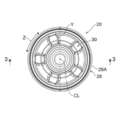
- FIG. 1 is a perspective view of a hole plug according to an embodiment of the present disclosure as viewed obliquely from above. It is a top view of the hole plug shown by FIG.
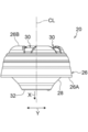
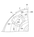
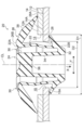
- FIG. 3 is a cross-sectional view taken along line 3-3 of the hole plug shown in FIG. 2; It is a side view of the hole plug shown by FIG. It is an enlarged view of the groove
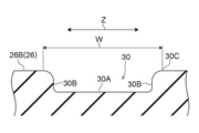
- FIG. 6 is a cross-sectional view taken along line 6-6 of the groove of the hole plug shown in FIG. 5; It is sectional drawing (sectional drawing corresponding to FIG. 3) of the hole plug which shows the state inserted in the 1st attachment hole of 2 panel members which piled up the hole plug shown in FIG. 1, and the 2nd attachment hole. It is sectional drawing (sectional drawing corresponding to FIG. 6) of the groove
- the hole plug 20 of the present embodiment is a member that closes the mounting hole formed in the plate-like portion of the mounting member.
- Arrows X shown in some of FIGS. 1 to 7 indicate the insertion direction of the hole plug 20 (hereinafter referred to as “plug insertion direction” as appropriate), and the arrow Y indicates the radial direction of the hole plug 20 (
- the “plug radial direction” is appropriately described, and the arrow Z indicates the circumferential direction of the hole plug 20 (hereinafter, appropriately described as “plug circumferential direction”).
- a symbol CL indicates a center line of the hole plug 20.
- the inner side in the plug radial direction refers to the side closer to the center line CL along the plug radial direction
- the outer side in the plug radial direction refers to the side farther from the center line CL along the plug radial direction.
- the hole plug 20 is to be attached to the attached member 12 and the attached member 14.
- the mounting member 12 has a plate-like portion 12A, and a through hole 13 is formed in the plate-like portion 12A.
- the through hole 13 has a diameter larger than that of a through hole 15 formed in a mounting member 14 described later. Specifically, the diameter D1 of the through hole 13 is larger than the diameter D2 of the through hole 15.
- the mounting member 12 is, for example, a panel member (a body panel or the like) of a vehicle.
- the mounting member 14 has a plate-like portion 14A, and a through hole 15 is formed in the plate-like portion 14A. Further, the mounting member 14 is mounted to the mounting member 12 in a state where the through hole 15 is aligned with the through hole 13 of the mounting member 12.
- the mounting member 14 is, for example, a bracket attached to a panel member of a vehicle. Further, the mounting member 14 of the present embodiment is an example of the mounting member in the present disclosure, and the through hole 15 is an example of the mounting hole of the mounting member in the present disclosure.
- the hole plug 20 includes an outer peripheral wall 22, a closing part 24, a flange 26, a claw 28 and a groove 30.
- the hole plug 20 of the present embodiment is an integrally molded product made of an elastically deformable resin.
- the outer peripheral wall part 22 is made cylindrical (this embodiment cylindrical shape), and it inserts in the through-hole 13 of the to-be-attached member 12, and the through-hole 15 of the to-be-attached member 14 It is supposed to be
- the cylindrical shape in the present embodiment includes those having a perfect circle and an elliptical cross-sectional shape.
- the toroidal ring includes a true circle and an ellipse.
- the closing portion 24 is bridged to the inside of the outer peripheral wall 22 and closes the inside of the outer peripheral wall 22. For this reason, in the engaged state in which the claws 28 of the hole plug 20 are engaged with the edge 15A of the through hole 15 of the mounting member 14 (hereinafter referred to as the "nail engaged state" as appropriate) The through hole 15 is closed by 24.
- the closed portion 24 has an annular projecting portion 32 projecting inward in the plug radial direction from the end 22B in the plug inserting direction of the outer peripheral wall portion 22 and an inner peripheral end of the projecting portion 32 opposite to the plug inserting direction
- a cylindrical inner peripheral wall portion 34 extending to the side and a face plate portion 36 bridged between the end portions of the inner peripheral wall portion 34 opposite to the plug insertion direction are provided.
- the flange portion 26 protrudes outward in the plug radial direction from the end 22A opposite to the plug insertion direction of the outer peripheral wall portion 22, and is annular (in this embodiment, annular) Is formed.
- the flange portion 26 of the present embodiment has a diameter D3 at the tip end portion 26A larger than the diameter D1 of the through hole 13 of the mounting member 12 in the unloaded state. For this reason, in the engaged state in which the claws 28 of the hole plug 20 are engaged with the edge 15A of the through hole 15 of the mounting member 14, the flange portion 26 and the periphery of the through hole 15 of the mounting member 14 and the mounting The periphery of the through hole 13 of the member 12 is covered (see FIG. 7).
- a raised portion 38 is formed on the surface of an intermediate portion between the distal end portion 26A and the proximal end portion 26B.
- the thickness of the raised portion 38 is thicker than the tip end 26A and the base end 26B of the flange 26.
- the claws 28 project outward from the end 22B of the outer peripheral wall 22 in the plug insertion direction toward the outer side in the plug radial direction and the opposite side to the plug insertion direction.
- the claws 28 are formed continuously along the outer periphery of the outer peripheral wall 22 and have an annular shape.
- the diameter D4 at the tip of the claw portion 28 is larger than the diameter D2 of the through hole 15 in the unloaded state.
- the claw portion 28 When the diameter-reduced claw portion 28 comes out of the through hole 15, the claw portion 28 is restored to the original state. Since the diameter D4 at the tip of the claw portion 28 is larger than the diameter D2 of the through hole 15, the force in the removal direction (the opposite direction to the insertion direction) is applied to the through hole 15 in the hole plug 20 When activated, the claws 28 engage (abut) the edge 15A of the through hole 15, and the movement in the removal direction is restricted (see FIG. 7).
- a plurality of grooves 30 are formed on the surface of the base end portion 26B of the flange portion 26 at intervals in the plug circumferential direction (the same direction as the circumferential direction of the flange portion 26). .
- the groove 30 extends from the outer peripheral wall 22 toward the flange 26 as shown in FIGS. 3 and 5. Specifically, the groove 30 is formed to straddle the end 22 B of the outer peripheral wall 22 and the base end 26 B of the flange 26.
- the groove 30 of the present embodiment is an example of the recess in the present disclosure.
- the bottom 30A of the groove 30 is flat.
- the portion of the hole plug 20 in which the groove 30 is formed has a reduced thickness.
- the groove width W of the groove 30 is larger at the opening 30C side than the bottom 30A.
- “the groove width W of the groove 30” is a length obtained by measuring the groove 30 along the plug circumferential direction.
- the opening width of the groove 30 is the largest at the base end portion 26 B of the flange portion 26.
- the “opening width of the groove 30” refers to the groove width at the opening 30C of the groove 30.
- five grooves 30 are formed on the surface of the base end portion 26B of the flange portion 26 at equal intervals in the circumferential direction of the plug.
- the groove width W is set such that the side wall portions 30B of the groove 30 do not abut each other even when the flange portion 26 is deformed to be parallel to the plug radial direction. .
- the outer peripheral wall portion 22 is inserted into the through hole 13 and the through hole 15 while pressing the face plate portion 36 of the closed portion 24.
- the claws 28 are restored and engaged with the edge 15 A of the through hole 15 as described above. This prevents the hole plug 20 from coming off the through hole 15.
- the outer peripheral wall portion 22 and the closing portion 24 close the through hole 15, and the flange portion 26 is the periphery of the through hole 15 of the mounting member 14 and the through hole 13 of the mounting member 12 Cover the periphery of the Therefore, the through hole 15 and the through hole 13 are blinded and stopped by the hole plug 20.
- the flange portion 26 since the plurality of grooves 30 are formed on the surface of the base end portion 26B of the flange portion 26, when the flange portion 26 abuts on the periphery of the through hole 13 at the time of insertion, The flange portion 26 is deformed starting from the groove 30. When the flange portion 26 is deformed, a force in the radial direction acts on the distal end portion 26A based on the insertion force of the hole plug 20, and a force in the radial direction acts on the proximal end portion 26B.
- the groove 30 is formed by forming the groove 30 on the surface of the proximal end 26B. Is a relief site for deformation due to external force, and the stress is reduced.
- the flange portion 26 is easily deformed starting from the groove 30, and the insertion force of the hole plug 20 into the through hole is reduced.
- the flange portion 26 is deformed starting from the groove 30 as compared with a configuration in which the bottom portion is sharp like a V-shaped cross section groove.
- the insertion force into the through hole is effectively reduced as compared with that in which a groove having a V-shaped cross section is formed on the surface of the base end 26B of the flange portion 26.
- the insertion force of the hole plug 20 into the through hole can be reduced, and therefore, the thickness of the flange portion 26 does not have to be reduced, and the occurrence of warpage of the flange portion 26 can be suppressed. .
- the groove 30 is extended from the outer peripheral wall portion 22 toward the flange portion 26, the groove 30 is added to the surface side of the base end portion 26B where an excessive stress is generated due to the deformation of the flange portion 26 Stress is also reduced in parts. Therefore, the insertion force of the hole plug 20 into the through hole is further reduced. Furthermore, in order to extend the groove 30 from the outer peripheral wall portion 22 toward the flange portion 26, the diameter of the base end portion 26B of the flange portion 26 is reduced. Specifically, as shown in FIG. 7, the proximal end 26B can be brought closer to the center line 26.
- the opening width of the groove 30 is the largest at the base end 26B of the flange portion 26, the groove 30 on the surface side of the base end 26B where excessive stress is generated by the deformation of the flange portion 26.
- the side wall portions 30B of the first and second side walls 30B are more difficult to contact with each other.
- the groove width W of the groove 30 is larger on the opening 30C side than the bottom 30A, for example, the groove width W of the groove 30 is the same on the bottom 30A and the opening 30C or on the opening 30C side than the bottom 30A.
- the side wall portions 30B of the groove 30 are less likely to abut each other when the flange portion 26 is deformed.
- the flange portion 26 can be deformed so as to be more parallel to the plug radial direction, and the mountable plate thickness tolerance It can be improved.
- the grooves 30 are formed in the flange portion 26 at equal intervals in the circumferential direction of the plug, when the flange portion 26 is deformed starting from the plurality of grooves 30, the flange portion 26 is made circumferentially It can be deformed (balanced) in a balanced manner. Furthermore, since five grooves 30 are formed in flange portion 26, that is, grooves 30 are formed at an angle of 72 degrees or less from center line CL, for example, an angle of four or less, ie, 90 degrees or more The flange portion 26 can be deformed (expanded) in a well-balanced manner in the circumferential direction of the plug as compared with the one formed by the above.
- the bottom 30A of the groove 30 is formed to be flat, but the present disclosure is not limited to this configuration.
- the bottom 40A may be formed in a curved surface like the groove 40 shown in FIG. Also in this case, the effect of reducing the insertion force of the hole plug into the through hole can be obtained as in the above-described embodiment.
- the bottom portion 40A of the groove 40 in a curved surface shape, it is possible to suppress concentration of stress on the bottom portion 40A when the flange portion 26 is deformed.
- the groove 30 extending from the outer peripheral wall 22 toward the flange 26 is formed on the surface of the base end 26B of the flange 26, but the present disclosure is not limited to this configuration.
- a circular or polygonal recess may be formed on the surface of the base end portion 26B of the flange portion 26.
- the opening width of the groove 30 is configured to be the largest at the base end 26B of the flange portion 26, but the present disclosure is not limited to this configuration.
- the opening width of the groove 30 may be the same in size from one end of the groove 30 to the other end.
- grooves 30 are formed in the flange portion 26 in the above embodiment, the present disclosure is not limited to this structure. For example, six or more may be sufficient.
- the claws 28 project from the end 22B side of the outer peripheral wall 22 (the end 22B side from the center of the outer peripheral wall 22 in the plug insertion direction), but the present disclosure is limited to this configuration I will not.
- the claws 28 may project from the end 22B of the outer peripheral wall 22.
- claw part 28 is formed in cyclic
- a plurality of claws 28 may be formed on the outer circumferential surface of the outer circumferential wall 22 at intervals in the circumferential direction of the plug.
- penetration hole 13 of mounting member 12 and penetration hole 15 of mounting member 14 are closed with hole plug 20
- this indication is not limited to this composition.
- the through-hole of one mounting member for example, panel material
- the through-hole of three or more mounting members may be closed.
- a cylindrical outer peripheral wall portion inserted into a mounting hole formed in the mounting member; A closed portion which is bridged inside the outer peripheral wall and closes the inside of the outer peripheral wall; An annular flange portion which projects from the end opposite to the insertion direction of the outer peripheral wall radially outward of the outer peripheral wall and covers the peripheral portion of the mounting hole; A claw that protrudes radially outward from an end side in the insertion direction of the outer peripheral wall and that engages with an edge of the mounting hole; A plurality of recesses formed on the surface of the base end portion of the flange portion at intervals in the circumferential direction of the flange portion, the bottom portion having a planar or curved surface shape; With a hole plug.
- the hole plug since a plurality of concave portions are formed on the surface of the base end portion of the flange portion, when the flange portion abuts on the peripheral portion of the mounting hole, the flange portion is deformed starting from these concave portions . In other words, the stress generated by the deformation of the flange portion is reduced by the plurality of recesses. For this reason, in the hole plug, for example, the insertion force into the mounting hole is reduced compared to the case where the recess is not formed on the surface of the base end portion of the flange portion.
- the flange portion is deformed starting from the recess as compared with the configuration in which the bottom is pointed like a V-shaped groove.
- the insertion force into the mounting hole is effectively reduced as compared with that in which the groove of the V-shaped cross section is formed on the surface of the base end portion of the flange portion.
- the recess is a groove extending from the outer peripheral wall toward the flange, stress is applied to the surface of the base end where excessive stress is generated due to deformation of the flange and also in the peripheral part Since the reduction is made, the insertion force into the mounting hole is further reduced.
- the opening width of the recess is the largest at the base end of the flange portion, the side wall portions of the recess are formed on the surface of the base end portion where excessive stress occurs due to deformation of the flange portion. Is more difficult to abut.
- the width of the recess is larger on the opening side than the bottom, for example, the width of the recess is the same on the bottom and the opening side or smaller than that on the opening At the time of deformation of the flange portion, it becomes difficult for the side wall portions of the recess to abut on each other.
- the flange portion is deformed in a well-balanced manner in the circumferential direction when the flange portion is deformed starting from a plurality of recessed portions. It is done (expanded).
- five or more concave portions are formed in the flange portion, that is, since the concave portions are formed at an angle of 72 degrees or less from the center of the outer peripheral wall portion, for example, four or less.
- the flange portion can be deformed (expanded) in a circumferential direction in a balanced manner as compared with the one formed at an angle of 90 degrees or more.
Landscapes
- Engineering & Computer Science (AREA)
- General Engineering & Computer Science (AREA)
- Mechanical Engineering (AREA)
- Chemical & Material Sciences (AREA)
- Combustion & Propulsion (AREA)
- Transportation (AREA)
- Pressure Vessels And Lids Thereof (AREA)
- Gasket Seals (AREA)
Priority Applications (2)
| Application Number | Priority Date | Filing Date | Title |
|---|---|---|---|
| CN201880083204.2A CN111512076B (zh) | 2017-12-27 | 2018-10-29 | 孔塞 |
| US16/957,789 US11493130B2 (en) | 2017-12-27 | 2018-10-29 | Hole plug |
Applications Claiming Priority (2)
| Application Number | Priority Date | Filing Date | Title |
|---|---|---|---|
| JP2017252223A JP6783748B2 (ja) | 2017-12-27 | 2017-12-27 | ホールプラグ |
| JP2017-252223 | 2017-12-27 |
Publications (1)
| Publication Number | Publication Date |
|---|---|
| WO2019130793A1 true WO2019130793A1 (ja) | 2019-07-04 |
Family
ID=67067030
Family Applications (1)
| Application Number | Title | Priority Date | Filing Date |
|---|---|---|---|
| PCT/JP2018/040191 Ceased WO2019130793A1 (ja) | 2017-12-27 | 2018-10-29 | ホールプラグ |
Country Status (4)
| Country | Link |
|---|---|
| US (1) | US11493130B2 (https=) |
| JP (1) | JP6783748B2 (https=) |
| CN (1) | CN111512076B (https=) |
| WO (1) | WO2019130793A1 (https=) |
Cited By (1)
| Publication number | Priority date | Publication date | Assignee | Title |
|---|---|---|---|---|
| US11493130B2 (en) | 2017-12-27 | 2022-11-08 | Nifco Inc. | Hole plug |
Families Citing this family (2)
| Publication number | Priority date | Publication date | Assignee | Title |
|---|---|---|---|---|
| US20220381343A1 (en) * | 2021-05-31 | 2022-12-01 | Illinois Tool Works Inc. | Sealing Plug |
| US20230349589A1 (en) * | 2022-04-29 | 2023-11-02 | Carrier Corporation | Hole plug for hvac component |
Citations (3)
| Publication number | Priority date | Publication date | Assignee | Title |
|---|---|---|---|---|
| JP2001124246A (ja) * | 1999-10-27 | 2001-05-11 | Kinugawa Rubber Ind Co Ltd | グロメット |
| JP2011158049A (ja) * | 2010-02-02 | 2011-08-18 | Piolax Inc | 留め具 |
| JP2014114850A (ja) * | 2012-12-07 | 2014-06-26 | Nifco Inc | ホールプラグ |
Family Cites Families (17)
| Publication number | Priority date | Publication date | Assignee | Title |
|---|---|---|---|---|
| FR2805503B1 (fr) * | 2000-02-28 | 2002-05-31 | Itw De France | Obturateur pour une ouverture realisee dans une tole |
| US7048486B2 (en) * | 2002-07-10 | 2006-05-23 | Newfrey Llc | Insert part for a wall opening, in particular on a vehicle body |
| JP4740124B2 (ja) * | 2004-05-24 | 2011-08-03 | 大和化成工業株式会社 | ホールプラグ |
| JP4896679B2 (ja) * | 2006-11-24 | 2012-03-14 | 株式会社パイオラックス | ホールプラグ |
| JP2011064296A (ja) * | 2009-09-18 | 2011-03-31 | Nifco Inc | ホールプラグ |
| JP5498890B2 (ja) * | 2009-11-12 | 2014-05-21 | 株式会社ニフコ | 自動車用の閉塞栓 |
| JP2012241843A (ja) * | 2011-05-23 | 2012-12-10 | Nifco Inc | ホールプラグ |
| ES2415758B1 (es) * | 2011-06-20 | 2014-09-09 | Illinois Tool Works, Inc. | Tapón obturador de orificios |
| JP5921353B2 (ja) * | 2011-11-16 | 2016-05-24 | 株式会社ニフコ | ホールプラグ |
| JP6088231B2 (ja) * | 2012-12-07 | 2017-03-01 | 株式会社ニフコ | ホールプラグ |
| JP5859467B2 (ja) * | 2013-01-09 | 2016-02-10 | 株式会社ニフコ | ホールプラグ |
| JP6122336B2 (ja) * | 2013-04-22 | 2017-04-26 | 大和化成工業株式会社 | ホールプラグ |
| JP6214335B2 (ja) * | 2013-10-24 | 2017-10-18 | 株式会社ニフコ | ホールプラグ |
| DE102015102169B4 (de) * | 2015-02-16 | 2016-08-25 | Trw Automotive Electronics & Components Gmbh | Verschlussstopfen |
| FR3032947B1 (fr) * | 2015-02-24 | 2020-02-21 | Itw Fastener Products Gmbh | Bouchons d'etancheite , assemblage et methode pour etancheifier une ouverture |
| CN204528016U (zh) * | 2015-04-04 | 2015-08-05 | 蒋祥初 | 气囊密封塞 |
| JP6783748B2 (ja) | 2017-12-27 | 2020-11-11 | トヨタ車体株式会社 | ホールプラグ |
-
2017
- 2017-12-27 JP JP2017252223A patent/JP6783748B2/ja active Active
-
2018
- 2018-10-29 CN CN201880083204.2A patent/CN111512076B/zh active Active
- 2018-10-29 WO PCT/JP2018/040191 patent/WO2019130793A1/ja not_active Ceased
- 2018-10-29 US US16/957,789 patent/US11493130B2/en active Active
Patent Citations (3)
| Publication number | Priority date | Publication date | Assignee | Title |
|---|---|---|---|---|
| JP2001124246A (ja) * | 1999-10-27 | 2001-05-11 | Kinugawa Rubber Ind Co Ltd | グロメット |
| JP2011158049A (ja) * | 2010-02-02 | 2011-08-18 | Piolax Inc | 留め具 |
| JP2014114850A (ja) * | 2012-12-07 | 2014-06-26 | Nifco Inc | ホールプラグ |
Cited By (1)
| Publication number | Priority date | Publication date | Assignee | Title |
|---|---|---|---|---|
| US11493130B2 (en) | 2017-12-27 | 2022-11-08 | Nifco Inc. | Hole plug |
Also Published As
| Publication number | Publication date |
|---|---|
| US11493130B2 (en) | 2022-11-08 |
| US20210372523A1 (en) | 2021-12-02 |
| JP6783748B2 (ja) | 2020-11-11 |
| CN111512076A (zh) | 2020-08-07 |
| JP2019116953A (ja) | 2019-07-18 |
| CN111512076B (zh) | 2022-05-06 |
Similar Documents
| Publication | Publication Date | Title |
|---|---|---|
| JP5880457B2 (ja) | グロメット | |
| WO2019130793A1 (ja) | ホールプラグ | |
| JP2014211224A (ja) | ホールプラグ | |
| WO2013073481A1 (ja) | ホールプラグ | |
| JP2015198528A (ja) | グロメット | |
| WO2018143257A1 (ja) | ホールプラグ | |
| US20190092397A1 (en) | Hole plug | |
| WO2014088043A1 (ja) | ホールプラグ | |
| WO2019130792A1 (ja) | ホールプラグの取付構造 | |
| JP6571367B2 (ja) | ホールプラグ | |
| JP2019116953A5 (https=) | ||
| JP2019075234A (ja) | グロメット | |
| JP2012007695A (ja) | 栓 | |
| WO2012157614A1 (ja) | ホールプラグ | |
| JP2005188623A (ja) | クリップ | |
| JP7211882B2 (ja) | 取付構造 | |
| JP5911790B2 (ja) | ホールプラグ | |
| JP6393150B2 (ja) | 防音カバー | |
| JP2019075233A (ja) | グロメット | |
| JP7191483B2 (ja) | 留め具 | |
| JP2013217448A (ja) | ホールプラグ | |
| JP2017007463A (ja) | グロメット及びグロメット付ワイヤハーネス | |
| JP2022175754A (ja) | ホールプラグ | |
| JP6131905B2 (ja) | グロメット | |
| JP2005299747A (ja) | ホールプラグ |
Legal Events
| Date | Code | Title | Description |
|---|---|---|---|
| 121 | Ep: the epo has been informed by wipo that ep was designated in this application |
Ref document number: 18897269 Country of ref document: EP Kind code of ref document: A1 |
|
| DPE1 | Request for preliminary examination filed after expiration of 19th month from priority date (pct application filed from 20040101) | ||
| NENP | Non-entry into the national phase |
Ref country code: DE |
|
| 122 | Ep: pct application non-entry in european phase |
Ref document number: 18897269 Country of ref document: EP Kind code of ref document: A1 |