WO2019130563A1 - 電気車制御装置 - Google Patents
電気車制御装置 Download PDFInfo
- Publication number
- WO2019130563A1 WO2019130563A1 PCT/JP2017/047306 JP2017047306W WO2019130563A1 WO 2019130563 A1 WO2019130563 A1 WO 2019130563A1 JP 2017047306 W JP2017047306 W JP 2017047306W WO 2019130563 A1 WO2019130563 A1 WO 2019130563A1
- Authority
- WO
- WIPO (PCT)
- Prior art keywords
- value
- command value
- current
- electric vehicle
- coupling
- Prior art date
- Legal status (The legal status is an assumption and is not a legal conclusion. Google has not performed a legal analysis and makes no representation as to the accuracy of the status listed.)
- Ceased
Links
Images





Classifications
-
- B—PERFORMING OPERATIONS; TRANSPORTING
- B60—VEHICLES IN GENERAL
- B60L—PROPULSION OF ELECTRICALLY-PROPELLED VEHICLES; SUPPLYING ELECTRIC POWER FOR AUXILIARY EQUIPMENT OF ELECTRICALLY-PROPELLED VEHICLES; ELECTRODYNAMIC BRAKE SYSTEMS FOR VEHICLES IN GENERAL; MAGNETIC SUSPENSION OR LEVITATION FOR VEHICLES; MONITORING OPERATING VARIABLES OF ELECTRICALLY-PROPELLED VEHICLES; ELECTRIC SAFETY DEVICES FOR ELECTRICALLY-PROPELLED VEHICLES
- B60L15/00—Methods, circuits, or devices for controlling the traction-motor speed of electrically-propelled vehicles
- B60L15/20—Methods, circuits, or devices for controlling the traction-motor speed of electrically-propelled vehicles for control of the vehicle or its driving motor to achieve a desired performance, e.g. speed, torque, programmed variation of speed
-
- B—PERFORMING OPERATIONS; TRANSPORTING
- B60—VEHICLES IN GENERAL
- B60L—PROPULSION OF ELECTRICALLY-PROPELLED VEHICLES; SUPPLYING ELECTRIC POWER FOR AUXILIARY EQUIPMENT OF ELECTRICALLY-PROPELLED VEHICLES; ELECTRODYNAMIC BRAKE SYSTEMS FOR VEHICLES IN GENERAL; MAGNETIC SUSPENSION OR LEVITATION FOR VEHICLES; MONITORING OPERATING VARIABLES OF ELECTRICALLY-PROPELLED VEHICLES; ELECTRIC SAFETY DEVICES FOR ELECTRICALLY-PROPELLED VEHICLES
- B60L3/00—Electric devices on electrically-propelled vehicles for safety purposes; Monitoring operating variables, e.g. speed, deceleration or energy consumption
- B60L3/0023—Detecting, eliminating, remedying or compensating for drive train abnormalities, e.g. failures within the drive train
- B60L3/0061—Detecting, eliminating, remedying or compensating for drive train abnormalities, e.g. failures within the drive train relating to electrical machines
-
- B—PERFORMING OPERATIONS; TRANSPORTING
- B60—VEHICLES IN GENERAL
- B60K—ARRANGEMENT OR MOUNTING OF PROPULSION UNITS OR OF TRANSMISSIONS IN VEHICLES; ARRANGEMENT OR MOUNTING OF PLURAL DIVERSE PRIME-MOVERS IN VEHICLES; AUXILIARY DRIVES FOR VEHICLES; INSTRUMENTATION OR DASHBOARDS FOR VEHICLES; ARRANGEMENTS IN CONNECTION WITH COOLING, AIR INTAKE, GAS EXHAUST OR FUEL SUPPLY OF PROPULSION UNITS IN VEHICLES
- B60K1/00—Arrangement or mounting of electrical propulsion units
- B60K1/02—Arrangement or mounting of electrical propulsion units comprising more than one electric motor
-
- B—PERFORMING OPERATIONS; TRANSPORTING
- B60—VEHICLES IN GENERAL
- B60L—PROPULSION OF ELECTRICALLY-PROPELLED VEHICLES; SUPPLYING ELECTRIC POWER FOR AUXILIARY EQUIPMENT OF ELECTRICALLY-PROPELLED VEHICLES; ELECTRODYNAMIC BRAKE SYSTEMS FOR VEHICLES IN GENERAL; MAGNETIC SUSPENSION OR LEVITATION FOR VEHICLES; MONITORING OPERATING VARIABLES OF ELECTRICALLY-PROPELLED VEHICLES; ELECTRIC SAFETY DEVICES FOR ELECTRICALLY-PROPELLED VEHICLES
- B60L53/00—Methods of charging batteries, specially adapted for electric vehicles; Charging stations or on-board charging equipment therefor; Exchange of energy storage elements in electric vehicles
- B60L53/20—Methods of charging batteries, specially adapted for electric vehicles; Charging stations or on-board charging equipment therefor; Exchange of energy storage elements in electric vehicles characterised by converters located in the vehicle
-
- B—PERFORMING OPERATIONS; TRANSPORTING
- B60—VEHICLES IN GENERAL
- B60L—PROPULSION OF ELECTRICALLY-PROPELLED VEHICLES; SUPPLYING ELECTRIC POWER FOR AUXILIARY EQUIPMENT OF ELECTRICALLY-PROPELLED VEHICLES; ELECTRODYNAMIC BRAKE SYSTEMS FOR VEHICLES IN GENERAL; MAGNETIC SUSPENSION OR LEVITATION FOR VEHICLES; MONITORING OPERATING VARIABLES OF ELECTRICALLY-PROPELLED VEHICLES; ELECTRIC SAFETY DEVICES FOR ELECTRICALLY-PROPELLED VEHICLES
- B60L9/00—Electric propulsion with power supply external to the vehicle
- B60L9/16—Electric propulsion with power supply external to the vehicle using AC induction motors
- B60L9/18—Electric propulsion with power supply external to the vehicle using AC induction motors fed from DC supply lines
-
- B—PERFORMING OPERATIONS; TRANSPORTING
- B60—VEHICLES IN GENERAL
- B60L—PROPULSION OF ELECTRICALLY-PROPELLED VEHICLES; SUPPLYING ELECTRIC POWER FOR AUXILIARY EQUIPMENT OF ELECTRICALLY-PROPELLED VEHICLES; ELECTRODYNAMIC BRAKE SYSTEMS FOR VEHICLES IN GENERAL; MAGNETIC SUSPENSION OR LEVITATION FOR VEHICLES; MONITORING OPERATING VARIABLES OF ELECTRICALLY-PROPELLED VEHICLES; ELECTRIC SAFETY DEVICES FOR ELECTRICALLY-PROPELLED VEHICLES
- B60L2200/00—Type of vehicles
- B60L2200/26—Rail vehicles
-
- B—PERFORMING OPERATIONS; TRANSPORTING
- B60—VEHICLES IN GENERAL
- B60L—PROPULSION OF ELECTRICALLY-PROPELLED VEHICLES; SUPPLYING ELECTRIC POWER FOR AUXILIARY EQUIPMENT OF ELECTRICALLY-PROPELLED VEHICLES; ELECTRODYNAMIC BRAKE SYSTEMS FOR VEHICLES IN GENERAL; MAGNETIC SUSPENSION OR LEVITATION FOR VEHICLES; MONITORING OPERATING VARIABLES OF ELECTRICALLY-PROPELLED VEHICLES; ELECTRIC SAFETY DEVICES FOR ELECTRICALLY-PROPELLED VEHICLES
- B60L2210/00—Converter types
- B60L2210/40—DC to AC converters
-
- B—PERFORMING OPERATIONS; TRANSPORTING
- B60—VEHICLES IN GENERAL
- B60L—PROPULSION OF ELECTRICALLY-PROPELLED VEHICLES; SUPPLYING ELECTRIC POWER FOR AUXILIARY EQUIPMENT OF ELECTRICALLY-PROPELLED VEHICLES; ELECTRODYNAMIC BRAKE SYSTEMS FOR VEHICLES IN GENERAL; MAGNETIC SUSPENSION OR LEVITATION FOR VEHICLES; MONITORING OPERATING VARIABLES OF ELECTRICALLY-PROPELLED VEHICLES; ELECTRIC SAFETY DEVICES FOR ELECTRICALLY-PROPELLED VEHICLES
- B60L2220/00—Electrical machine types; Structures or applications thereof
- B60L2220/10—Electrical machine types
- B60L2220/12—Induction machines
-
- B—PERFORMING OPERATIONS; TRANSPORTING
- B60—VEHICLES IN GENERAL
- B60L—PROPULSION OF ELECTRICALLY-PROPELLED VEHICLES; SUPPLYING ELECTRIC POWER FOR AUXILIARY EQUIPMENT OF ELECTRICALLY-PROPELLED VEHICLES; ELECTRODYNAMIC BRAKE SYSTEMS FOR VEHICLES IN GENERAL; MAGNETIC SUSPENSION OR LEVITATION FOR VEHICLES; MONITORING OPERATING VARIABLES OF ELECTRICALLY-PROPELLED VEHICLES; ELECTRIC SAFETY DEVICES FOR ELECTRICALLY-PROPELLED VEHICLES
- B60L2220/00—Electrical machine types; Structures or applications thereof
- B60L2220/40—Electrical machine applications
- B60L2220/42—Electrical machine applications with use of more than one motor
-
- B—PERFORMING OPERATIONS; TRANSPORTING
- B60—VEHICLES IN GENERAL
- B60L—PROPULSION OF ELECTRICALLY-PROPELLED VEHICLES; SUPPLYING ELECTRIC POWER FOR AUXILIARY EQUIPMENT OF ELECTRICALLY-PROPELLED VEHICLES; ELECTRODYNAMIC BRAKE SYSTEMS FOR VEHICLES IN GENERAL; MAGNETIC SUSPENSION OR LEVITATION FOR VEHICLES; MONITORING OPERATING VARIABLES OF ELECTRICALLY-PROPELLED VEHICLES; ELECTRIC SAFETY DEVICES FOR ELECTRICALLY-PROPELLED VEHICLES
- B60L2240/00—Control parameters of input or output; Target parameters
- B60L2240/40—Drive Train control parameters
- B60L2240/42—Drive Train control parameters related to electric machines
- B60L2240/421—Speed
-
- B—PERFORMING OPERATIONS; TRANSPORTING
- B60—VEHICLES IN GENERAL
- B60L—PROPULSION OF ELECTRICALLY-PROPELLED VEHICLES; SUPPLYING ELECTRIC POWER FOR AUXILIARY EQUIPMENT OF ELECTRICALLY-PROPELLED VEHICLES; ELECTRODYNAMIC BRAKE SYSTEMS FOR VEHICLES IN GENERAL; MAGNETIC SUSPENSION OR LEVITATION FOR VEHICLES; MONITORING OPERATING VARIABLES OF ELECTRICALLY-PROPELLED VEHICLES; ELECTRIC SAFETY DEVICES FOR ELECTRICALLY-PROPELLED VEHICLES
- B60L2240/00—Control parameters of input or output; Target parameters
- B60L2240/40—Drive Train control parameters
- B60L2240/42—Drive Train control parameters related to electric machines
- B60L2240/423—Torque
-
- B—PERFORMING OPERATIONS; TRANSPORTING
- B60—VEHICLES IN GENERAL
- B60L—PROPULSION OF ELECTRICALLY-PROPELLED VEHICLES; SUPPLYING ELECTRIC POWER FOR AUXILIARY EQUIPMENT OF ELECTRICALLY-PROPELLED VEHICLES; ELECTRODYNAMIC BRAKE SYSTEMS FOR VEHICLES IN GENERAL; MAGNETIC SUSPENSION OR LEVITATION FOR VEHICLES; MONITORING OPERATING VARIABLES OF ELECTRICALLY-PROPELLED VEHICLES; ELECTRIC SAFETY DEVICES FOR ELECTRICALLY-PROPELLED VEHICLES
- B60L2240/00—Control parameters of input or output; Target parameters
- B60L2240/40—Drive Train control parameters
- B60L2240/42—Drive Train control parameters related to electric machines
- B60L2240/427—Voltage
-
- B—PERFORMING OPERATIONS; TRANSPORTING
- B60—VEHICLES IN GENERAL
- B60L—PROPULSION OF ELECTRICALLY-PROPELLED VEHICLES; SUPPLYING ELECTRIC POWER FOR AUXILIARY EQUIPMENT OF ELECTRICALLY-PROPELLED VEHICLES; ELECTRODYNAMIC BRAKE SYSTEMS FOR VEHICLES IN GENERAL; MAGNETIC SUSPENSION OR LEVITATION FOR VEHICLES; MONITORING OPERATING VARIABLES OF ELECTRICALLY-PROPELLED VEHICLES; ELECTRIC SAFETY DEVICES FOR ELECTRICALLY-PROPELLED VEHICLES
- B60L2240/00—Control parameters of input or output; Target parameters
- B60L2240/40—Drive Train control parameters
- B60L2240/42—Drive Train control parameters related to electric machines
- B60L2240/429—Current
-
- B—PERFORMING OPERATIONS; TRANSPORTING
- B60—VEHICLES IN GENERAL
- B60L—PROPULSION OF ELECTRICALLY-PROPELLED VEHICLES; SUPPLYING ELECTRIC POWER FOR AUXILIARY EQUIPMENT OF ELECTRICALLY-PROPELLED VEHICLES; ELECTRODYNAMIC BRAKE SYSTEMS FOR VEHICLES IN GENERAL; MAGNETIC SUSPENSION OR LEVITATION FOR VEHICLES; MONITORING OPERATING VARIABLES OF ELECTRICALLY-PROPELLED VEHICLES; ELECTRIC SAFETY DEVICES FOR ELECTRICALLY-PROPELLED VEHICLES
- B60L2240/00—Control parameters of input or output; Target parameters
- B60L2240/40—Drive Train control parameters
- B60L2240/52—Drive Train control parameters related to converters
- B60L2240/529—Current
-
- Y—GENERAL TAGGING OF NEW TECHNOLOGICAL DEVELOPMENTS; GENERAL TAGGING OF CROSS-SECTIONAL TECHNOLOGIES SPANNING OVER SEVERAL SECTIONS OF THE IPC; TECHNICAL SUBJECTS COVERED BY FORMER USPC CROSS-REFERENCE ART COLLECTIONS [XRACs] AND DIGESTS
- Y02—TECHNOLOGIES OR APPLICATIONS FOR MITIGATION OR ADAPTATION AGAINST CLIMATE CHANGE
- Y02T—CLIMATE CHANGE MITIGATION TECHNOLOGIES RELATED TO TRANSPORTATION
- Y02T10/00—Road transport of goods or passengers
- Y02T10/60—Other road transportation technologies with climate change mitigation effect
- Y02T10/64—Electric machine technologies in electromobility
-
- Y—GENERAL TAGGING OF NEW TECHNOLOGICAL DEVELOPMENTS; GENERAL TAGGING OF CROSS-SECTIONAL TECHNOLOGIES SPANNING OVER SEVERAL SECTIONS OF THE IPC; TECHNICAL SUBJECTS COVERED BY FORMER USPC CROSS-REFERENCE ART COLLECTIONS [XRACs] AND DIGESTS
- Y02—TECHNOLOGIES OR APPLICATIONS FOR MITIGATION OR ADAPTATION AGAINST CLIMATE CHANGE
- Y02T—CLIMATE CHANGE MITIGATION TECHNOLOGIES RELATED TO TRANSPORTATION
- Y02T10/00—Road transport of goods or passengers
- Y02T10/60—Other road transportation technologies with climate change mitigation effect
- Y02T10/70—Energy storage systems for electromobility, e.g. batteries
-
- Y—GENERAL TAGGING OF NEW TECHNOLOGICAL DEVELOPMENTS; GENERAL TAGGING OF CROSS-SECTIONAL TECHNOLOGIES SPANNING OVER SEVERAL SECTIONS OF THE IPC; TECHNICAL SUBJECTS COVERED BY FORMER USPC CROSS-REFERENCE ART COLLECTIONS [XRACs] AND DIGESTS
- Y02—TECHNOLOGIES OR APPLICATIONS FOR MITIGATION OR ADAPTATION AGAINST CLIMATE CHANGE
- Y02T—CLIMATE CHANGE MITIGATION TECHNOLOGIES RELATED TO TRANSPORTATION
- Y02T10/00—Road transport of goods or passengers
- Y02T10/60—Other road transportation technologies with climate change mitigation effect
- Y02T10/7072—Electromobility specific charging systems or methods for batteries, ultracapacitors, supercapacitors or double-layer capacitors
-
- Y—GENERAL TAGGING OF NEW TECHNOLOGICAL DEVELOPMENTS; GENERAL TAGGING OF CROSS-SECTIONAL TECHNOLOGIES SPANNING OVER SEVERAL SECTIONS OF THE IPC; TECHNICAL SUBJECTS COVERED BY FORMER USPC CROSS-REFERENCE ART COLLECTIONS [XRACs] AND DIGESTS
- Y02—TECHNOLOGIES OR APPLICATIONS FOR MITIGATION OR ADAPTATION AGAINST CLIMATE CHANGE
- Y02T—CLIMATE CHANGE MITIGATION TECHNOLOGIES RELATED TO TRANSPORTATION
- Y02T10/00—Road transport of goods or passengers
- Y02T10/60—Other road transportation technologies with climate change mitigation effect
- Y02T10/72—Electric energy management in electromobility
-
- Y—GENERAL TAGGING OF NEW TECHNOLOGICAL DEVELOPMENTS; GENERAL TAGGING OF CROSS-SECTIONAL TECHNOLOGIES SPANNING OVER SEVERAL SECTIONS OF THE IPC; TECHNICAL SUBJECTS COVERED BY FORMER USPC CROSS-REFERENCE ART COLLECTIONS [XRACs] AND DIGESTS
- Y02—TECHNOLOGIES OR APPLICATIONS FOR MITIGATION OR ADAPTATION AGAINST CLIMATE CHANGE
- Y02T—CLIMATE CHANGE MITIGATION TECHNOLOGIES RELATED TO TRANSPORTATION
- Y02T90/00—Enabling technologies or technologies with a potential or indirect contribution to GHG emissions mitigation
- Y02T90/10—Technologies relating to charging of electric vehicles
- Y02T90/14—Plug-in electric vehicles
Definitions
- the present invention relates to an electric vehicle control apparatus applied to an electric vehicle in which one inverter drives a plurality of induction motors and the plurality of induction motors drive the same.
- a motor is connected and connected to a wheel axle mounted on a truck of an electric vehicle via a gear and a coupling. It controls the torque generated by the motor to drive the electric car. Moreover, it is common to use an induction motor as a motor.
- Patent Document 2 when the rotational speed of the motor detected by the speed detector exceeds the maximum speed setting value, the operation of the inverter is stopped to suppress an abnormal increase in the rotational speed of the motor.
- An electric vehicle control system is disclosed.
- a coupling which is a connecting member for connecting between an induction motor and a gear, may come off during traveling.
- an electric vehicle driven by a plurality of induction motors is pulled by the induction motor which is not disengaged even if the coupling of some of the induction motors is disengaged.
- the present invention has been made in view of the above, and it is an object of the present invention to obtain an electric vehicle control device capable of detecting the disengagement of the coupling by an easy method.
- the present invention is a total of a plurality of induction motors, one inverter for driving a plurality of induction motors, and a motor current flowing in each induction motor. Based on a current detector that detects a total current, a current command value calculated based on a torque command value, a voltage command value calculated based on a detected total current, and a calculated voltage command value and a detected total current And a controller for controlling the inverter based on the calculated speed estimated value.
- the driving control system controls the traveling of the electric car.
- the control device calculates a torque estimated value based on the total current and the voltage command value, and is provided between the induction motor and the drive mechanism of the electric vehicle based on the calculated torque estimated value and the torque command value.
- a coupling removal detection unit is provided to detect coupling removal.
- the present invention in the electric vehicle control device, it is possible to detect the disengagement of the coupling by an easy method.
- FIG. 3 is a block diagram showing an example of the configuration of the control device according to Embodiment 1 different from FIG.
- Block diagram showing the detailed configuration of the control device according to the second embodiment Flowchart showing the operation flow of the coupling removal detection in the second embodiment
- Block diagram showing the detailed configuration of the control device according to the third embodiment Flowchart showing the operation flow of the coupling removal detection in the third embodiment
- a block diagram showing an example of a hardware configuration for realizing the function of the coupling loss detection unit in the first, second and third embodiments A block diagram showing another example of a hardware configuration for realizing the function of the coupling loss detection unit in the first, second and third embodiments
- connection an electric vehicle control device according to an embodiment of the present invention will be described in detail with reference to the attached drawings.
- the present invention is not limited by the following embodiments. Also, in the following description, physical connection and electrical connection are simply referred to as “connection” without distinction.
- FIG. 1 is a block diagram of an electric vehicle drive system 80 including the electric vehicle control device according to the first embodiment.
- FIG. 1 shows an example of application to a DC electric vehicle.
- the electric vehicle drive system 80 according to the first embodiment includes an input circuit 3, a first drive group 50, and a second drive group 52.
- the first drive group 50 constitutes a first drive control system
- the second drive group 52 constitutes a second drive control system.
- the first drive group 50 and the second drive group 52 control the traveling of the electric vehicle.
- the positive side of the input circuit 3 is connected to the overhead wire 11 via the pantograph 15, and the negative side of the input circuit 3 is in contact with the rail 18 via the wheels 16.
- the first drive group 50 and the second drive group 52 are connected in parallel to the output side of the input circuit 3.
- one electric circuit is configured among the overhead wire 11, the pantograph 15, the input circuit 3, the first drive group 50, the wheel 16 and the rail 18.
- another electric circuit is configured among the overhead wire 11, the pantograph 15, the input circuit 3, the second drive group 52, the wheel 16 and the rail 18.
- Power from the overhead wire 11 is supplied to the input circuit 3 via the pantograph 15. Further, the electric power from the overhead wire 11 through the pantograph 15 and the input circuit 3 is supplied to the first drive group 50 and the second drive group 52.
- the input circuit 3 has a breaker 22, a filter capacitor 24 and a voltage detector 26.
- the circuit breaker 22 opens and closes the connection between the overhead wire 11 and the first drive group 50 and the second drive group 52.
- the filter capacitor 24 smoothes and stores the power supplied from the overhead wire 11.
- the voltage detector 26 detects the voltage of the filter capacitor 24.
- the first drive group 50 includes an inverter 1, two induction motors 2, a control device 4, and a current detector 5.
- the connection terminal on the high potential side of the inverter 1 is connected to the pantograph 15 via the circuit breaker 22 of the input circuit 3, and the connection terminal on the low potential side of the inverter 1 is electrically connected to the wheel 16 through the input circuit 3.
- the inverter 1 is a power conversion device that converts direct current supplied from the input circuit 3 into alternating current of variable voltage and variable frequency.
- the two induction motors 2 are connected to the AC side of the inverter 1.
- the side on which the input circuit 3 is present is referred to as the “DC side”
- the side on which the induction motor 2 is present is referred to as the “AC side”.
- the inverter 1 drives two induction motors 2.
- the two induction motors 2 apply a driving force to the electric vehicle.
- the current detector 5 is disposed between the inverter 1 and the connection point 9 of the two induction motors 2.
- the current detector 5 detects total currents i u , i v and i w which are the sum of motor currents flowing in each of the two induction motors 2.
- the motor current is a phase current flowing in each phase of one induction motor 2.
- the total current i u , i v , i w detected by the current detector 5 is input to the control device 4.
- a filter capacitor voltage v FC which is a detected value of the voltage detector 26 is input to the control device 4.
- Control device 4 generates a gate drive signal for driving switching element 1a of inverter 1 based on the information of total current i u , i v , i w , rotational speed ⁇ d and filter capacitor voltage v FC. Output to the inverter 1.
- the control device 4 generates a PWM signal for pulse width modulation (PWM) control of the inverter 1 which is a power conversion device.
- PWM pulse width modulation
- the second drive group 52 is also configured similarly to the first drive group 50.
- the components of the second drive group 52 are the same as those of the first drive group 50, and the description here is omitted.
- FIG. 1 shows an application example to a DC electric vehicle
- the present invention is also applicable to an AC electric vehicle.
- the configuration of the input circuit 3 is different, the basic configuration of the control device 4 is equivalent.
- FIG. 1 illustrates two drive groups including the first drive group 50 and the second drive group 52, it is needless to say that the present invention can be applied to three or more drive groups.
- FIG. 1 shows an example in which two induction motors 2 are connected to one inverter 1, the present invention is not limited to this example. In a vehicle on which the induction motor 2 is mounted, it is general that one vehicle has two carriages, and two carriage motors are mounted on one carriage. Therefore, in the general configuration, when one control device 4 is mounted on one vehicle, the four induction motors 2 are driven by the one control device 4.
- the electric vehicle drive system 80 according to the first embodiment is configured such that one inverter 1 drives a plurality of induction motors 2 that drive the electric vehicle.
- the control device 4 constitutes an electric vehicle control device according to the first embodiment.
- the electric vehicle drive system 80 according to the first embodiment is not provided with a speed sensor for detecting the rotational speed of the induction motor 2. That is, the control device 4 according to the first embodiment is a control device that performs so-called speed sensorless control that does not use the detection value of the speed sensor for control.
- the function of the control device 4 is the same in each drive group. Therefore, in the following, description will be given focusing on one control device 4 that controls one drive group.
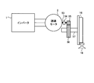
- FIG. 2 is a view showing a schematic configuration of a drive mechanism between the wheel 16 of the electric vehicle and the induction motor 2.
- a coupling 54 as a connecting member is provided on the rotation shaft 53 of the induction motor 2 and is connected to the motor side gear 55.
- the motor-side gear 55 is disposed so as to mesh with the wheel-side gear 56.
- the wheel gear 56 is fixed to the axle 57.
- the motor side gear 55 and the wheel side gear 56 constitute a gear of an electric car.
- Wheels 16 are connected to the axles 57.
- a mechanism that transmits the mechanical output of the induction motor 2 to the wheel 16 via the axle 57 is provided.
- the electric car drives the wheels 16 to rotate and travels on the rails 18 in contact with the wheels 16.
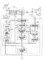
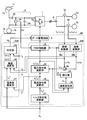
- FIG. 3 is a block diagram showing a detailed configuration of the control device 4 according to the first embodiment.
- the same or equivalent parts as those shown in FIG. 1 are denoted by the same reference numerals.
- the control device 4 has a gate drive circuit 8, a voltage control unit 30, and a coupling removal detection unit 40.
- the gate drive circuit 8 generates a gate drive signal for driving the switching element 1 a of the inverter 1 and outputs the gate drive signal to the inverter 1.
- the voltage control unit 30 generates a PWM signal for PWM control of the inverter 1 and outputs the PWM signal to the gate drive circuit 8.
- the coupling removal detecting unit 40 detects whether or not coupling removal has occurred in the induction motor 2 to be driven.
- Voltage control unit 30 includes torque command value calculation unit 31, current command value calculation unit 32, voltage command value calculation unit 33, integrator 34, PWM control unit 35, coordinate conversion unit 36, and speed estimation unit. And 38.
- the coordinate conversion unit 36 converts the total current i u , i v , i w detected by the current detector 5 into current values of d axis and q axis which are two axes of the rotating coordinate system.
- the converted current values are the d-axis current id and the q-axis current iq .
- the d axis is an axis called a magnetic flux axis
- the q axis is an axis called a torque axis.
- the d axis and the q axis are each in a vector orthogonal relationship.
- the conversion processing by the coordinate conversion unit 36 is known, and the description here is omitted.
- the d-axis current id and the q-axis current iq converted by the coordinate conversion unit 36 are input to the voltage command value calculation unit 33, the speed estimation unit 38, and the coupling loss detection unit 40.
- the start command C s is input to the torque command value calculation unit 31.
- the start command C s is a command that is output when the traveling of the electric vehicle is started.
- Torque command value calculating unit 31 a trigger input of a start command C s, and calculates the torque command value T m *.
- the torque command value T m * is a command value of torque to be output to the induction motor 2.
- the torque command value T m * calculated by the torque command value calculation unit 31 is input to the current command value calculation unit 32.
- the current command value calculation unit 32 calculates the q-axis current command value i q * , which is the current command value of the torque axis, and the d-axis current command value i, which is the current command value of the magnetic flux axis. Calculate d * .
- the calculation processing in the current command value calculation unit 32 is known, and the description here is omitted.
- Q-axis current command value current command value calculating section 32 calculates i q * and d-axis current command value i d * is input to the voltage command value calculating unit 33.
- Voltage command value calculation unit 33 calculates d-axis current command value id * and q-axis current command value iq * calculated by current command value calculation unit 32, and d-axis current i which is an output of coordinate conversion unit 36.
- the d- axis voltage command value v d * and the q-axis voltage command value v q * are calculated based on the d and q-axis current iq .
- the voltage command value is a command value of the voltage output from the inverter 1. In the case of vector control, it is a general method to divide and calculate in the d-axis direction and the q-axis direction.
- the calculation processing in the voltage command value calculation unit 33 is known, and the description here is omitted.
- the d-axis voltage command value v d * and the q-axis voltage command value v q * calculated by the voltage command value calculation unit 33 are input to the PWM control unit 35, the speed estimation unit 38, and the coupling loss detection unit 40. Ru.
- the speed estimation unit 38 calculates the estimated speed value ⁇ e by calculation based on the d-axis current id and the q-axis current i q , and the d-axis voltage command value v d * and the q-axis voltage command value v q *. .
- the estimated speed value ⁇ e calculated by the speed estimation unit 38 is input to the integrator 34.
- the integrator 34 obtains an angular frequency by internal calculation based on the input estimated speed value ⁇ e , integrates the obtained angular frequency, and calculates the phase ⁇ i .
- the angular frequency can be generated by adding the slip speed of the induction motor 2 to the speed estimated value ⁇ e .
- Phase theta i of the integrator 34 is calculated includes a PWM control unit 35, is inputted to the coordinate transformation unit 36. In the coordinate transformation unit 36, the phase theta i is used when calculating the d-axis current i d and the q-axis current i q.
- the PWM control unit 35 performs PWM control of the switching element 1 a of the inverter 1 based on the phase ⁇ i , the d-axis voltage command value v d * and the q-axis voltage command value v q * , and the filter capacitor voltage v FC . Generate a PWM signal.
- the generation process of the PWM signal is known, and the description here is omitted.
- the coupling removal detecting unit 40 includes a torque estimating unit 41, a deviation calculating unit 42, and a determining unit 43.
- the coupling removal detection unit 40 is a detection unit that detects removal of the coupling 54 provided on the rotation shaft 53 of the induction motor 2.
- the torque command value T m * calculated based on the start command C s and the total current i u , i v , i w detected by the current detector 5 between the torque estimate T e is calculated based on, it appears differences can detect coupling off. This difference is particularly noticeable at startup.
- the start time includes not only the case where the vehicle is shifted from the stopped state to the traveling state, but also the case where the vehicle is accelerated again from the coasting state. Also, the difference referred to herein is not a difference caused by chance or an error but a significant difference.
- the coupling removal detection unit 40 shown in FIG. 3 is configured using this principle.
- the torque estimation unit 41 and the d-axis current i d and the q-axis current i q that has been converted by the coordinate conversion unit 36, the d-axis voltage command value calculated by the voltage command value calculator 33 v d * and the q-axis voltage
- the command value v q * and the start command C s are input.
- Torque estimating unit 41 when the start command C s is input, a d-axis current i d and the q-axis current i q, the d-axis voltage command value v d *, q-axis voltage command value v q * and the based on, it calculates the torque estimated value T e.
- the estimated torque value Te is not an externally input or designated value, but an estimated torque value calculated by a control parameter in the controller 4.
- Torque estimate T e of the torque estimation unit 41 computed is input to the deviation calculation unit 42.
- a torque command value T m * is input to the deviation calculation unit 42.
- the deviation calculation unit 42 calculates the absolute value
- of the deviation is input to the determination unit 43.
- the reference value T s is input to the determination unit 43.
- the reference value T s is a threshold for detecting coupling loss.
- Determining unit 43 the absolute value of the deviation
- Determining unit 43 outputs a detection signal H d out to determine the coupling out occurs.
- the deviation detection signal Hd is output to the gate drive circuit 8.
- the deviation detection signal Hd is a control signal for forcibly stopping the operation of the gate drive circuit 8. While the disconnection detection signal Hd is output, the gate drive circuit 8 stops the output of the gate drive signal to the inverter 1 even if the PWM signal from the PWM control unit 35 is input.
- a start command C s to torque estimation unit 41 may be configured to enter a start command C s to the determination unit 43.
- the torque estimation unit 41 processing by the deviation calculation unit 42 and the judging unit 43 is made at all times.
- the determination result of the determination unit 43 is outputted to the gate driver circuit 8.
- the determination unit 43 according to the input of the start command C s starts operating, the determination result of the determination unit 43 is outputted to the gate driver circuit 8.
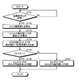
- FIG. 4 is a flowchart showing an operation flow of the coupling removal detection in the first embodiment.
- the processes of steps S101 and S102 are performed by the torque estimation unit 41
- the process of step S103 is performed by the deviation calculation unit 42
- the processes of steps S104 to S107 are performed by the determination unit 43.
- step S101 it is determined whether a start command C s has been received. If the start command C s has not been received (step S101, No), the process of step S101 is repeated. If receiving the activation command C s (step S101, Yes), the process proceeds to step S102.
- step S102 an estimated torque value Te is calculated.
- step S103 a deviation ⁇ T between the estimated torque value Te and the torque command value Tm * is calculated.
- step S104 the absolute value of the calculated deviation [Delta] T in step S103
- step S105 the absolute value
- the process proceeds to step S106.
- step S106 it is determined that "coupling is not present", and the process flow of FIG. 4 ends.
- step S105 the absolute value
- step S107 it is determined that "coupling is not lost", and the processing flow of FIG. 4 is ended.
- step S105 when the absolute value
- the coupling loss of the induction motor 2 is detected based on the torque command value T m * and the torque estimated value T e.
- the method according to the first embodiment may use the command information on torque “torque command value T m * ” and the estimated information on torque “torque estimated value T e ”, so that the decoupling of the induction motor 2 can be performed by a simple method. It becomes possible to detect.
- the coupling removal of a part of the induction motor 2 is detected, and the coupling removal is detected.
- Drive of the drive group can be stopped. Thereby, even if the drive of only one drive group including the induction motor 2 in the coupling-off state is stopped, the operation of the electric vehicle can be continued by the other drive group.
- FIG. 5 is a block diagram showing a configuration example of the control device 4 according to the first embodiment which is different from FIG.
- the difference from FIG. 3 is an output destination of out detecting signal H d. That is, in FIG. 3, whereas the outputs of the out detecting signal H d to the gate drive circuit 8, FIG. 5, and outputs a disconnection detection signal H d in breaker 22. Breaker has been received out detecting signal H d 22, by opening the contacts, not shown, to cut off the electric power supplied from the overhead wire 11.
- the configuration of FIG. 3 has the advantage that the operation of the electric vehicle can be continued.
- the configuration of FIG. 5 since the drive of only one drive group including the induction motor 2 in the coupling-off state can not be stopped, the operation of the electric vehicle can not be continued.
- the configuration of FIG. 5 since the power supply can be shut off on the side closer to the overhead wire 11, there is an advantage that the operation of the electric vehicle can be stopped promptly.
- the configuration of FIG. 5 is effective for avoiding such a situation.
- FIG. 6 is a block diagram showing a detailed configuration of the control device 4A according to the second embodiment.
- the control device 4A according to the second embodiment includes a voltage control unit 30A and a coupling removal detection unit 40A.
- the torque estimating unit 41 is changed to the speed converting unit 44, and the deviation calculating unit 42 is converted to the deviation calculating unit 45.
- the determination unit 43 is changed to the determination unit 46.
- the remaining configuration is the same as or equivalent to the configuration of the first embodiment except for input / output signals, and the same or equivalent components are denoted by the same reference numerals and redundant description will be omitted. The input and output signals will be described later.
- the coupling removal detection unit 40A is a detection unit that detects removal of the coupling 54 provided on the rotation shaft 53 of the induction motor 2.
- speed estimation calculated based on the actual rotation speed of the induction motor 2 and the total current i u , i v , i w detected by the current detector 5
- the coupling loss detection unit 40A shown in FIG. 5 is configured using this principle.
- a vehicle speed V s which is vehicle speed information from the outside, is input to the speed conversion unit 44.
- the vehicle speed information may use information on traveling speed managed by the train, or may use actual detection information on the traveling speed.
- the speed conversion unit 44 converts the vehicle speed V s into a converted speed ⁇ c .
- the converted speed ⁇ c is a converted value obtained by converting the vehicle speed V s into the rotational speed of the induction motor 2.
- the conversion speed ⁇ c calculated by the speed conversion unit 44 is input to the deviation calculation unit 45.
- the deviation calculation unit 45 in addition to the conversion speed omega c, the speed estimated value omega e is inputted.
- the deviation calculating unit 45 calculates the absolute value
- of the deviation is input to the determination unit 46.
- the reference value ⁇ s is input to the determination unit 46 in addition to the absolute value
- the reference value ⁇ s is a threshold for detecting coupling loss.
- Determination unit 46 the absolute value of the deviation
- the disconnection detection signal Hd is output to the gate drive circuit 8, but may be output to the circuit breaker 22 as shown in FIG.
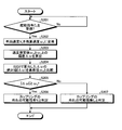
- FIG. 7 is a flowchart showing an operation flow of the coupling removal detection in the second embodiment.
- the processing of steps S201 and S202 is performed by the speed conversion unit 44
- the processing of step S203 is performed by the deviation calculation unit 45
- the processing of steps S204 to S207 is performed by the determination unit 46.
- step S201 it is determined whether a start command C s has been received. If not received the start command C s (step S201, No), it repeats the processing in step S201. If receiving the activation command C s (step S201, Yes), the process proceeds to step S202.
- step S202 the vehicle speed V s is converted to the converted speed ⁇ c .
- step S203 the deviation ⁇ between the estimated speed value ⁇ e and the converted speed ⁇ c is calculated.
- step S204 the absolute value
- the reference value ⁇ s is set as a determination value for preventing false detection due to noise or the like. That is, the reference value ⁇ s is a setting value provided to improve the accuracy of the coupling removal detection.
- step S205 when the absolute value
- step S206 it is determined that "coupling is not present", and the processing flow of FIG. 7 ends.
- step S207 it is determined that "coupling is not lost", and the processing flow of FIG. 7 is ended.
- step S205 the case where the absolute value
- the coupling loss of the induction motor 2 can be detected based on the vehicle speed V s and the estimated speed value ⁇ e. . Since the method according to the second embodiment may use input information on the speed of the vehicle speed V s and estimated information on the speed of the speed estimated value ⁇ e, the coupling loss of the induction motor 2 is detected by a simple method. It becomes possible.
- the coupling removal of a part of the induction motor 2 is detected, and the coupling removal is detected.
- Drive of the drive group can be stopped. Thereby, even if the drive of only one drive group including the induction motor 2 in the coupling-off state is stopped, the operation of the electric vehicle can be continued by the other drive group.
- FIG. 6 and outputs a disconnection detection signal H d to the gate drive circuit 8, as in FIG. 5, may output a disconnection detection signal H d in breaker 22.
- a disconnection detection signal H d By outputting the disconnection detection signal Hd to the circuit breaker 22, the effect of the configuration shown in FIG. 5 described in the first embodiment can be obtained.
- FIG. 8 is a block diagram showing a detailed configuration of the control device 4B according to the third embodiment.
- the control device 4B according to the third embodiment includes a voltage control unit 30B and a coupling removal detection unit 40B.
- the speed conversion unit 44 is changed to a current value conversion unit 47, and the deviation calculation unit 45 is a deviation calculation unit 48.
- the determination unit 46 is changed to the determination unit 49.
- the control device 4B instead of providing the current detector 5 between the inverter 1 and the connection point 9, the current detector 5a, between the connection point 9 and the induction motor 2 5b is provided.
- the coordinate conversion unit 36 is replaced with coordinate conversion units 36a and 36b, and an adder 39 is further added.
- the induction motor on the side of the current detector 5a is described as the induction motor 2a
- the induction motor on the side of the current detector 5b is described as the induction motor 2b.
- the other configuration is the same as or equivalent to the configuration of the second embodiment, and the same or equivalent configuration parts are assigned the same reference numerals and redundant descriptions will be omitted.
- the current detector 5a detects individual motor currents i u1 , i v1 and i w1 flowing to the induction motor 2a.
- the current detector 5b detects individual motor currents i u2 , i v2 and i w2 flowing to the induction motor 2 b.
- the detected values of the motor currents i u1 , i v1 and i w1 detected by the current detector 5 a are input to the coordinate conversion unit 36 a.
- the coordinate conversion unit 36a converts the motor currents i u1 , i v1 , i w1 detected by the current detector 5 a into current values of d axis and q axis.
- the converted current values are the d-axis current id1 and the q-axis current iq1 .
- the d-axis current id1 and the q-axis current iq1 converted by the coordinate conversion unit 36 a are input to the adder 39.
- the q-axis current iq1 of the d-axis current id1 and the q-axis current iq1 is input to the deviation calculation unit 48 of the coupling loss detection unit 40B.
- the detected values of the motor currents i u2 , i v2 and i w2 detected by the current detector 5 b are input to the coordinate conversion unit 36 b.
- the coordinate conversion unit 36 b converts the motor currents i u2 , i v2 and i w2 detected by the current detector 5 b into d-axis and q-axis current values.
- the converted current values are the d-axis current id2 and the q-axis current iq2 .
- the d-axis current id2 and the q-axis current iq2 converted by the coordinate conversion unit 36b are input to the adder 39.
- the q-axis current iq2 of the d-axis current id2 and the q-axis current iq2 is input to the deviation calculation unit 48 of the coupling loss detection unit 40B.
- the adder 39 adds the d-axis current id1 and the d-axis current id2 and adds the q-axis current iq1 and the q-axis current iq2 , and adds the sum to the voltage command value calculation unit 33 , And the speed estimation unit 38.
- the output of the adder 39, a motor current flowing in the induction motor 2a, a motor current flowing in the induction motor 2b is summed d-axis current i d and the q-axis current i q.
- the coupling removal detection unit 40B is a detection unit that detects removal of the coupling 54 provided on the rotation shaft 53 of the induction motor 2. When driving the induction motor 2 with the coupling 54 removed, it is between the actual motor current flowing through the individual induction motor 2 and the q-axis current command value iq * calculated based on the torque command value T m * There is a difference that can detect the coupling loss. This difference is particularly noticeable at startup. Also, this difference appears notably in the current component in the q-axis direction.
- the coupling removal detection unit 40B shown in FIG. 8 is configured using this principle.
- the current value conversion portion 47, a q-axis current command value i q * calculated by the current command value calculating section 32, and a start command C s is inputted.
- the current value conversion unit 47 derives the q-axis current command value i q * , which is a command value in the q-axis direction of two motor currents flowing through the induction motors 2a and 2b. It converts into q-axis current command value iq1 * per any one of motor 2a or induction motor 2b.
- the q-axis current command value iq 1 * converted by the current value conversion unit 47 is input to the deviation calculation unit 48.
- Deviation calculation unit 48 receives, in addition to q-axis current command value i q1 * , q-axis current i q1 converted by coordinate conversion unit 36 a and q-axis current i q2 converted by coordinate conversion unit 36 b. Ru. Deviation calculation unit 48, the absolute value of the deviation between the q-axis current command value i q1 * and the q-axis current i q1
- ⁇ I 1 Calculate the absolute value
- of the deviation is input to the determination unit 49.
- the determination unit 49 the absolute value of the deviation
- the reference value I s is a threshold for detecting the coupling loss.
- the determination unit 49 compares each of the deviation absolute values
- the determination unit 49 determines the coupling out occurs in the induction motor 2b detection signal H d of the gate drive circuit Output to 8.
- the disconnection detection signal Hd is output to the gate drive circuit 8, but may be output to the circuit breaker 22 as shown in FIG. 5.
- the q-axis current command value iq * is input to the current value conversion unit 47, and the q-axis current command value iq1 * , the q-axis current iq1 and the q-axis current iq2 are input to the deviation calculation unit 48.
- the d-axis current command value id * is input to the current value conversion unit 47, and the d-axis current command value id1 * , the d-axis current id1 and the d-axis current id2 are input to the deviation calculation unit 48.
- the command value and the current value of the d-axis current may be used for the determination of the coupling loss.
- a start command C s to the current value conversion portion 47 may be configured to enter a start command C s to the determining unit 49.
- processing by the current value conversion portion 47, the error calculator 48 and determining unit 49 is constantly performed. Then, according to the input of the start command C s, the determination result of the determination unit 49 is outputted to the gate driver circuit 8.
- processing by the current value conversion portion 47 and a deviation computing unit 48 is performed at all times. Then, the determination unit 49 according to the input of the start command C s starts operating, the determination result of the determination unit 49 is outputted to the gate driver circuit 8.
- FIG. 9 is a flowchart showing an operation flow of the coupling removal detection in the third embodiment.
- the processes of steps S301 and S302 are performed by the current value conversion unit 47
- the process of step S303 is performed by the deviation calculation unit 48
- the processes of steps S304 to S307 are performed by the determination unit 49.
- step S301 it is determined whether the start command C s has been received. If not received the start command C s (step S301, No), it repeats the processing in step S301. If receiving the activation command C s (step S301, Yes), the process proceeds to step S302.
- step S302 q axis current command value i q * is converted to i q1 * q-axis current command value per unit.
- step S303 deviations ⁇ I 1 and ⁇ I 2 between each of the q-axis current command values iq1 * and iq2 * and each of the q-axis currents iq1 and iq2 calculated based on the detected values are calculated.
- step S304 the absolute values
- step S305 if at least one of the absolute values
- step S305 if both of the absolute values
- step S307 it is determined that "coupling is not lost", and the processing flow of FIG. 9 is ended.
- step S305 when the absolute values
- the case where it is equal to s may be determined as “No”, and the process may move to step S307. That is, when the absolute values
- the q-axis current i q1 , i calculated based on the detection value of each motor current flowing to each of the induction motors 2a and 2b.
- the coupling loss of the induction motor 2 can be detected based on q2 and the q-axis current command value iq1 * per unit calculated based on the q-axis current command value iq * .
- the q-axis currents iq1 and iq2 can be calculated using the detected values of the currents flowing through the respective induction motors 2a and 2b.
- the method of the third embodiment may use the control parameter of q-axis current command value i q * and the detection information of current detectors 5a and 5b, so the coupling removal of induction motor 2 can be simplified. It becomes possible to detect by the method.
- the coupling removal of the induction motors 2a and 2b is detected, and the driving of the drive group including the induction motor 2a or 2b whose coupling removal is detected is stopped. be able to. Thus, even if the drive of only one drive group including the induction motors 2a and 2b in the coupling-off state is stopped, the operation of the electric vehicle can be continued by the other drive group.
- the electric vehicle control device according to the third embodiment, it becomes possible to specify which of the induction motors 2a and 2b is out of the coupling. As a result, compared to the electric vehicle control device according to the first and second embodiments, the effect of facilitating the failure search and maintenance work can be obtained.
- a processor 100 performing calculation and a program read by the processor 100. May be stored in the memory 102 and an interface 104 for inputting and outputting signals.
- the processor 100 may be an arithmetic unit, a microprocessor, a microcomputer, a central processing unit (CPU), or a digital signal processor (DSP).
- the memory 102 may be a nonvolatile or volatile semiconductor memory, such as a random access memory (RAM), a read only memory (ROM), a flash memory, an erasable programmable ROM (EPROM), or an electrically EPROM (registered trademark).
- RAM random access memory
- ROM read only memory
- EPROM erasable programmable ROM
- EPROM erasable programmable ROM
- electrically EPROM registered trademark
- Magnetic disks flexible disks, optical disks, compact disks, mini disks, and DVDs (Digital Versatile Disc).
- the memory 102 stores programs for executing the functions of the coupling removal detecting unit 40, the coupling removal detecting unit 40A, and the coupling removal detecting unit 40B.
- the processor 100 transmits and receives necessary information via the interface 104, and the processor 100 executes a program stored in the memory 102 to perform various kinds of arithmetic processing described in the first, second, and third embodiments. Run.
- the processing result by the processor 100 can be stored in the memory 102.
- the processor 100 and the memory 102 shown in FIG. 10 may be replaced with the processing circuit 103 as shown in FIG.
- the processing circuit 103 may be a single circuit, a complex circuit, a programmed processor, a parallel programmed processor, an application specific integrated circuit (ASIC), a field-programmable gate array (FPGA), or a combination thereof. .
Landscapes
- Engineering & Computer Science (AREA)
- Transportation (AREA)
- Mechanical Engineering (AREA)
- Power Engineering (AREA)
- Life Sciences & Earth Sciences (AREA)
- Sustainable Development (AREA)
- Sustainable Energy (AREA)
- Chemical & Material Sciences (AREA)
- Combustion & Propulsion (AREA)
- Electric Propulsion And Braking For Vehicles (AREA)
- Control Of Multiple Motors (AREA)
- Control Of Electric Motors In General (AREA)
Abstract
Description
図1は、実施の形態1に係る電気車制御装置を含む電気車駆動システム80の構成図である。図1は、直流電気車への適用例である。図1に示すように、実施の形態1に係る電気車駆動システム80は、入力回路3と、第1の駆動群50と、第2の駆動群52とを有する。第1の駆動群50は第1の駆動制御系を構成し、第2の駆動群52は第2の駆動制御系を構成する。第1の駆動群50及び第2の駆動群52は、電気車の走行を制御する。
図6は、実施の形態2に係る制御装置4Aの詳細構成を示すブロック図である。実施の形態2に係る制御装置4Aは、電圧制御部30Aと、カップリング外れ検出部40Aとを備える。
図8は、実施の形態3に係る制御装置4Bの詳細構成を示すブロック図である。実施の形態3に係る制御装置4Bは、電圧制御部30Bと、カップリング外れ検出部40Bとを備える。
Claims (6)
- 複数台の誘導モータと、複数台の前記誘導モータを駆動する1つのインバータと、各々の前記誘導モータに流れるモータ電流の合計であるトータル電流を検出する電流検出器と、トルク指令値に基づいて算出した電流指令値、検出された前記トータル電流に基づいて算出した電圧指令値、並びに、算出した前記電圧指令値及び検出した前記トータル電流に基づいて算出した速度推定値に基づいて前記インバータを制御する制御装置と、を有する駆動制御系を備え、前記駆動制御系によって電気車を走行制御する電気車制御装置であって、
前記制御装置は、
前記トータル電流と前記電圧指令値とに基づいてトルク推定値を算出し、算出した前記トルク推定値と前記トルク指令値とに基づいて、前記誘導モータと前記電気車の駆動機構との間に設けられたカップリングの外れを検出するカップリング外れ検出部を備えたことを特徴とする電気車制御装置。 - 前記カップリング外れ検出部は、
前記トルク推定値を推定する推定部と、
前記トルク指令値と前記トルク推定値との偏差の絶対値を演算する演算部と、
前記偏差の絶対値と基準値とを比較し、前記偏差の絶対値が前記基準値よりも大きいときにカップリング外れが生じていると判定する判定部と、
を備えたことを特徴とする請求項1に記載の電気車制御装置。 - 複数台の誘導モータと、複数台の前記誘導モータを駆動する1つのインバータと、各々の前記誘導モータに流れるモータ電流の合計であるトータル電流を検出する電流検出器と、トルク指令値及び検出された前記トータル電流に基づいて算出した電圧指令値、並びに、算出した前記電圧指令値及び検出した前記トータル電流に基づいて算出した速度推定値に基づいて前記インバータを制御する制御装置と、を有する駆動制御系を備え、前記駆動制御系によって電気車を走行制御する電気車制御装置であって、
前記制御装置は、
前記電気車の走行速度を用いて算出した前記誘導モータの回転速度と、前記速度推定値とに基づいて、前記誘導モータと前記電気車の駆動機構との間に設けられたカップリングの外れを検出するカップリング外れ検出部を備えたことを特徴とする電気車制御装置。 - 前記カップリング外れ検出部は、
前記電気車の走行速度を前記誘導モータの前記回転速度に換算する換算部と、
前記回転速度と前記速度推定値との偏差の絶対値を演算する演算部と、
前記偏差の絶対値と基準値とを比較し、前記偏差の絶対値が前記基準値よりも大きいときにカップリング外れが生じていると判定する判定部と、
を備えたことを特徴とする請求項3に記載の電気車制御装置。 - 複数台の誘導モータと、複数台の前記誘導モータを駆動する1つのインバータと、各々が前記誘導モータに流れる個々のモータ電流を検出する複数の電流検出器と、トルク指令値に基づいて算出した電流指令値、検出された個々の前記モータ電流の加算値に基づいて算出した電圧指令値、並びに、算出した前記電圧指令値及び前記モータ電流の加算値に基づいて算出した速度推定値に基づいて前記インバータを制御する制御装置と、を有する駆動制御系を備え、前記駆動制御系によって電気車を走行制御する電気車制御装置であって、
前記制御装置は、
各々の誘導モータに流れる個々の前記モータ電流の検出値に基づいて算出されるq軸電流と、前記電流指令値のうちのq軸電流指令値とに基づいて、各々の前記誘導モータと前記電気車の駆動機構との間に設けられたカップリングの外れを検出するカップリング外れ検出部を備えたことを特徴とする電気車制御装置。 - 前記カップリング外れ検出部は、
前記q軸電流指令値を前記誘導モータの1台当たりのq軸電流指令値に換算する換算部と、
各々の前記誘導モータにおける前記q軸電流と、前記q軸電流指令値との偏差の絶対値を演算する演算部と、
前記偏差の絶対値と基準値とを比較し、前記偏差の絶対値が前記基準値よりも大きいときにカップリング外れが生じていると判定する判定部と、
を備えたことを特徴とする請求項5に記載の電気車制御装置。
Priority Applications (4)
| Application Number | Priority Date | Filing Date | Title |
|---|---|---|---|
| DE112017008321.4T DE112017008321B4 (de) | 2017-12-28 | 2017-12-28 | Elektrofahrzeugsteuerung mit einer kupplungstrennungs-detektionseinheit |
| US16/956,745 US11518247B2 (en) | 2017-12-28 | 2017-12-28 | Electric vehicle controller |
| JP2019562691A JP6851504B2 (ja) | 2017-12-28 | 2017-12-28 | 電気車制御装置 |
| PCT/JP2017/047306 WO2019130563A1 (ja) | 2017-12-28 | 2017-12-28 | 電気車制御装置 |
Applications Claiming Priority (1)
| Application Number | Priority Date | Filing Date | Title |
|---|---|---|---|
| PCT/JP2017/047306 WO2019130563A1 (ja) | 2017-12-28 | 2017-12-28 | 電気車制御装置 |
Publications (1)
| Publication Number | Publication Date |
|---|---|
| WO2019130563A1 true WO2019130563A1 (ja) | 2019-07-04 |
Family
ID=67063331
Family Applications (1)
| Application Number | Title | Priority Date | Filing Date |
|---|---|---|---|
| PCT/JP2017/047306 Ceased WO2019130563A1 (ja) | 2017-12-28 | 2017-12-28 | 電気車制御装置 |
Country Status (4)
| Country | Link |
|---|---|
| US (1) | US11518247B2 (ja) |
| JP (1) | JP6851504B2 (ja) |
| DE (1) | DE112017008321B4 (ja) |
| WO (1) | WO2019130563A1 (ja) |
Cited By (4)
| Publication number | Priority date | Publication date | Assignee | Title |
|---|---|---|---|---|
| WO2021166839A1 (ja) * | 2020-02-18 | 2021-08-26 | 株式会社デンソー | 異常診断システムおよび異常診断方法 |
| WO2023053248A1 (ja) * | 2021-09-29 | 2023-04-06 | 株式会社Subaru | 電動車両の制御装置及び電動車両並びにコンピュータプログラムを記録した記録媒体 |
| US20230309443A1 (en) * | 2021-09-24 | 2023-10-05 | Nanjing Chervon Industry Co., Ltd. | Riding lawn mower |
| US12568880B2 (en) | 2021-09-18 | 2026-03-10 | Nanjing Chervon Industry Co., Ltd. | Riding lawn mower, display interface of a power tool and riding machine |
Citations (5)
| Publication number | Priority date | Publication date | Assignee | Title |
|---|---|---|---|---|
| JPH0956005A (ja) * | 1995-08-18 | 1997-02-25 | Hitachi Ltd | 電気車の制御装置 |
| JPH09107602A (ja) * | 1995-10-09 | 1997-04-22 | Hitachi Ltd | 電気車の制御装置 |
| JP2004264208A (ja) * | 2003-03-03 | 2004-09-24 | Jfe Steel Kk | ローラーテーブルの設備診断方法 |
| JP2006067731A (ja) * | 2004-08-27 | 2006-03-09 | Mitsubishi Electric Corp | 電動パワーステアリング装置 |
| WO2011080822A1 (ja) * | 2009-12-28 | 2011-07-07 | 三菱電機株式会社 | 電気車の電力変換装置 |
Family Cites Families (42)
| Publication number | Priority date | Publication date | Assignee | Title |
|---|---|---|---|---|
| IT1239384B (it) * | 1990-03-13 | 1993-10-20 | Fi Re Ma System S P A | Metodo e dispositivo per il controllo di un sistema di trazione su rotaia con ruote indipendenti singolarmente motorizzate |
| US6307759B1 (en) * | 1997-10-31 | 2001-10-23 | Hitachi, Ltd. | Control device for electric power translating device |
| JP2002315101A (ja) * | 2001-04-13 | 2002-10-25 | Mitsubishi Electric Corp | 電気車駆動制御装置 |
| JP2003134603A (ja) * | 2001-10-29 | 2003-05-09 | Toshiba Corp | 電気車の制御装置 |
| JP3732784B2 (ja) * | 2002-01-22 | 2006-01-11 | 財団法人鉄道総合技術研究所 | 電気車の駆動制御方法および制御装置 |
| JP2004080936A (ja) * | 2002-08-20 | 2004-03-11 | Railway Technical Res Inst | 加速度推定装置、電動機制御装置及び加速度推定方法 |
| JP2004328991A (ja) * | 2003-04-09 | 2004-11-18 | Nissan Motor Co Ltd | 車両の左右輪駆動装置 |
| JP3900358B2 (ja) * | 2003-12-15 | 2007-04-04 | 三菱電機株式会社 | 電気車制御装置 |
| US7733044B2 (en) * | 2005-02-24 | 2010-06-08 | Mitsubishi Heavy Industries, Ltd. | IPM motor system and control method thereof |
| CN101091119B (zh) * | 2005-04-01 | 2010-08-18 | 三菱电机株式会社 | 电车控制装置 |
| JP2008017609A (ja) * | 2006-07-05 | 2008-01-24 | Toshiba Corp | 電気車制御装置 |
| DE102006045397A1 (de) * | 2006-09-26 | 2008-04-03 | Siemens Ag | Fehlererkennung durch Auswertung von Größen der feldorientierten Regelung |
| WO2008053554A1 (fr) * | 2006-11-02 | 2008-05-08 | Mitsubishi Electric Corporation | Appareil de commande de voiture à moteur électrique |
| JP2008167586A (ja) * | 2006-12-28 | 2008-07-17 | Nissan Motor Co Ltd | 車両用駆動制御装置 |
| JP4476314B2 (ja) * | 2007-08-10 | 2010-06-09 | 三洋電機株式会社 | モータ制御装置及び圧縮機 |
| US20100191399A1 (en) * | 2007-10-18 | 2010-07-29 | Mitsubishi Electric Corporation | Wheel diameter measuring apparatus of electric vehicle |
| JP4877296B2 (ja) * | 2008-08-21 | 2012-02-15 | トヨタ自動車株式会社 | 駆動装置およびその制御装置 |
| JP4782218B2 (ja) * | 2009-06-10 | 2011-09-28 | 新日本製鐵株式会社 | 設備の異常診断方法 |
| ES2602809T3 (es) * | 2009-12-28 | 2017-02-22 | Mitsubishi Electric Corporation | Dispositivo de control de accionamiento de motor de corriente alterna |
| JP5528154B2 (ja) | 2010-02-23 | 2014-06-25 | 東洋電機製造株式会社 | 電気車制御装置 |
| JP6043045B2 (ja) * | 2010-06-28 | 2016-12-14 | 株式会社東芝 | 車両用制御システム |
| JP5190156B2 (ja) * | 2010-07-28 | 2013-04-24 | 三菱電機株式会社 | 交流回転機の制御装置 |
| US9203332B2 (en) * | 2011-06-30 | 2015-12-01 | Ntn Corporation | Motor drive device |
| KR101898755B1 (ko) * | 2011-08-18 | 2018-09-13 | 히다찌 겐끼 가부시키가이샤 | 모터 제어 장치 및 그것을 사용한 작업 기계 |
| US9209736B2 (en) * | 2011-10-03 | 2015-12-08 | General Electric Company | System and method for traction motor control |
| ES2590138T3 (es) * | 2011-11-30 | 2016-11-18 | Mitsubishi Electric Corporation | Dispositivo inversor para vehículo eléctrico |
| JP2013135501A (ja) * | 2011-12-26 | 2013-07-08 | Aisin Seiki Co Ltd | モータ駆動車両の制御装置及び制御方法 |
| JP5354036B2 (ja) * | 2012-01-19 | 2013-11-27 | トヨタ自動車株式会社 | 車両および車両の制御方法 |
| US9160272B2 (en) * | 2012-01-20 | 2015-10-13 | Mitsubishi Electric Corporation | Control device and control method for permanent magnet motor |
| JP2013183532A (ja) * | 2012-03-01 | 2013-09-12 | Toshiba Corp | モータ制御装置及びその制御方法 |
| JP5296942B1 (ja) * | 2012-07-20 | 2013-09-25 | 三菱電機株式会社 | 制御装置 |
| JPWO2015020009A1 (ja) * | 2013-08-07 | 2017-03-02 | 株式会社東芝 | 車両用制御装置及び鉄道車両 |
| JP5666043B2 (ja) | 2014-05-30 | 2015-02-04 | 株式会社東芝 | 電気車制御装置およびトルク指令生成方法 |
| WO2016063375A1 (ja) * | 2014-10-22 | 2016-04-28 | 三菱電機株式会社 | 軌間可変電車の制御装置 |
| JP6277288B2 (ja) * | 2014-11-28 | 2018-02-07 | 株式会社日立産機システム | 監視装置と監視方法およびそれらを備える制御装置と制御方法 |
| US20160229433A1 (en) * | 2015-02-06 | 2016-08-11 | Electro-Motive Diesel, Inc. | Automatic disabling of unpowered locked wheel fault detection |
| US9463817B2 (en) * | 2015-02-16 | 2016-10-11 | Electro-Motive Diesel, Inc. | Automatic disabling of unpowered locked wheel fault detection for slipped traction motor pinion |
| US20170087990A1 (en) * | 2015-09-29 | 2017-03-30 | General Electric Company | System and method for predicting mechanical failure |
| JP6483039B2 (ja) * | 2016-01-26 | 2019-03-13 | 株式会社日立製作所 | 電力変換装置 |
| JP6143905B1 (ja) * | 2016-03-08 | 2017-06-07 | 三菱電機株式会社 | 回転電機駆動装置の制御装置 |
| JP6765320B2 (ja) * | 2017-02-28 | 2020-10-07 | 株式会社日立産機システム | 交流電動機の制御装置 |
| DE102017208157A1 (de) * | 2017-05-15 | 2018-11-15 | Siemens Aktiengesellschaft | Verfahren und Vorrichtung zur Überwachung eines Antriebssystems |
-
2017
- 2017-12-28 US US16/956,745 patent/US11518247B2/en active Active
- 2017-12-28 WO PCT/JP2017/047306 patent/WO2019130563A1/ja not_active Ceased
- 2017-12-28 JP JP2019562691A patent/JP6851504B2/ja active Active
- 2017-12-28 DE DE112017008321.4T patent/DE112017008321B4/de active Active
Patent Citations (5)
| Publication number | Priority date | Publication date | Assignee | Title |
|---|---|---|---|---|
| JPH0956005A (ja) * | 1995-08-18 | 1997-02-25 | Hitachi Ltd | 電気車の制御装置 |
| JPH09107602A (ja) * | 1995-10-09 | 1997-04-22 | Hitachi Ltd | 電気車の制御装置 |
| JP2004264208A (ja) * | 2003-03-03 | 2004-09-24 | Jfe Steel Kk | ローラーテーブルの設備診断方法 |
| JP2006067731A (ja) * | 2004-08-27 | 2006-03-09 | Mitsubishi Electric Corp | 電動パワーステアリング装置 |
| WO2011080822A1 (ja) * | 2009-12-28 | 2011-07-07 | 三菱電機株式会社 | 電気車の電力変換装置 |
Cited By (7)
| Publication number | Priority date | Publication date | Assignee | Title |
|---|---|---|---|---|
| WO2021166839A1 (ja) * | 2020-02-18 | 2021-08-26 | 株式会社デンソー | 異常診断システムおよび異常診断方法 |
| JP2021131590A (ja) * | 2020-02-18 | 2021-09-09 | 株式会社デンソー | 異常診断システムおよび異常診断方法 |
| JP7176543B2 (ja) | 2020-02-18 | 2022-11-22 | 株式会社デンソー | 異常診断システム、異常診断方法およびコンピュータプログラム |
| US12568880B2 (en) | 2021-09-18 | 2026-03-10 | Nanjing Chervon Industry Co., Ltd. | Riding lawn mower, display interface of a power tool and riding machine |
| US20230309443A1 (en) * | 2021-09-24 | 2023-10-05 | Nanjing Chervon Industry Co., Ltd. | Riding lawn mower |
| WO2023053248A1 (ja) * | 2021-09-29 | 2023-04-06 | 株式会社Subaru | 電動車両の制御装置及び電動車両並びにコンピュータプログラムを記録した記録媒体 |
| JP7502573B2 (ja) | 2021-09-29 | 2024-06-18 | 株式会社Subaru | 電動車両の制御装置及び電動車両並びにコンピュータプログラムを記録した記録媒体 |
Also Published As
| Publication number | Publication date |
|---|---|
| US11518247B2 (en) | 2022-12-06 |
| DE112017008321T5 (de) | 2020-09-03 |
| DE112017008321B4 (de) | 2026-02-19 |
| US20200317058A1 (en) | 2020-10-08 |
| JP6851504B2 (ja) | 2021-03-31 |
| JPWO2019130563A1 (ja) | 2020-06-18 |
Similar Documents
| Publication | Publication Date | Title |
|---|---|---|
| US8228008B2 (en) | Motor controlling apparatus | |
| JP4455248B2 (ja) | 誘導電動機のベクトル制御装置 | |
| CN102668368B (zh) | 电动车辆的功率转换装置 | |
| CN101536303A (zh) | 电车控制装置 | |
| JP6246496B2 (ja) | 電気自動車の制御装置 | |
| JP6851504B2 (ja) | 電気車制御装置 | |
| JP2010246328A (ja) | インバータの故障診断装置 | |
| JP4573835B2 (ja) | 電気車制御装置 | |
| JPWO2011064846A1 (ja) | 電気車の電力変換装置 | |
| JP7035609B2 (ja) | 駆動装置 | |
| WO2019171836A1 (ja) | 車両制御装置 | |
| KR20140121858A (ko) | 모터 제어 장치 및 그 제어 방법 | |
| JP2012114974A (ja) | 電気車制御装置 | |
| JP6854925B2 (ja) | 電気車制御装置 | |
| TWI556996B (zh) | Trolley control device | |
| JP7038924B2 (ja) | 推進制御装置および推進制御方法 | |
| JP2009240123A (ja) | 電動機制御方法及び電動機制御装置 | |
| JP5359668B2 (ja) | エレベーターの制御装置 | |
| JP2005312126A (ja) | 電気車制御装置 | |
| JP5618690B2 (ja) | 電気車制御装置 | |
| JP2010063287A (ja) | 電気車制御装置 | |
| JP4141654B2 (ja) | 鉄道車両駆動用リニア誘導電動機の制御装置 | |
| JP4425818B2 (ja) | 誘導電動機の駆動制御装置 | |
| JP6142845B2 (ja) | 車両制御装置 | |
| JP2018011412A (ja) | 電気車制御装置 |
Legal Events
| Date | Code | Title | Description |
|---|---|---|---|
| 121 | Ep: the epo has been informed by wipo that ep was designated in this application |
Ref document number: 17936256 Country of ref document: EP Kind code of ref document: A1 |
|
| ENP | Entry into the national phase |
Ref document number: 2019562691 Country of ref document: JP Kind code of ref document: A |
|
| WWE | Wipo information: entry into national phase |
Ref document number: 112017008321 Country of ref document: DE |
|
| 122 | Ep: pct application non-entry in european phase |
Ref document number: 17936256 Country of ref document: EP Kind code of ref document: A1 |
|
| WWG | Wipo information: grant in national office |
Ref document number: 112017008321 Country of ref document: DE |