WO2019123871A1 - 画像表示装置 - Google Patents
画像表示装置 Download PDFInfo
- Publication number
- WO2019123871A1 WO2019123871A1 PCT/JP2018/041346 JP2018041346W WO2019123871A1 WO 2019123871 A1 WO2019123871 A1 WO 2019123871A1 JP 2018041346 W JP2018041346 W JP 2018041346W WO 2019123871 A1 WO2019123871 A1 WO 2019123871A1
- Authority
- WO
- WIPO (PCT)
- Prior art keywords
- opening
- image display
- screw
- display unit
- display device
- Prior art date
Links
Images


Classifications
-
- G—PHYSICS
- G02—OPTICS
- G02F—OPTICAL DEVICES OR ARRANGEMENTS FOR THE CONTROL OF LIGHT BY MODIFICATION OF THE OPTICAL PROPERTIES OF THE MEDIA OF THE ELEMENTS INVOLVED THEREIN; NON-LINEAR OPTICS; FREQUENCY-CHANGING OF LIGHT; OPTICAL LOGIC ELEMENTS; OPTICAL ANALOGUE/DIGITAL CONVERTERS
- G02F1/00—Devices or arrangements for the control of the intensity, colour, phase, polarisation or direction of light arriving from an independent light source, e.g. switching, gating or modulating; Non-linear optics
- G02F1/01—Devices or arrangements for the control of the intensity, colour, phase, polarisation or direction of light arriving from an independent light source, e.g. switching, gating or modulating; Non-linear optics for the control of the intensity, phase, polarisation or colour
- G02F1/13—Devices or arrangements for the control of the intensity, colour, phase, polarisation or direction of light arriving from an independent light source, e.g. switching, gating or modulating; Non-linear optics for the control of the intensity, phase, polarisation or colour based on liquid crystals, e.g. single liquid crystal display cells
- G02F1/133—Constructional arrangements; Operation of liquid crystal cells; Circuit arrangements
- G02F1/1333—Constructional arrangements; Manufacturing methods
- G02F1/133308—Support structures for LCD panels, e.g. frames or bezels
-
- H—ELECTRICITY
- H04—ELECTRIC COMMUNICATION TECHNIQUE
- H04N—PICTORIAL COMMUNICATION, e.g. TELEVISION
- H04N5/00—Details of television systems
- H04N5/64—Constructional details of receivers, e.g. cabinets or dust covers
-
- G—PHYSICS
- G02—OPTICS
- G02F—OPTICAL DEVICES OR ARRANGEMENTS FOR THE CONTROL OF LIGHT BY MODIFICATION OF THE OPTICAL PROPERTIES OF THE MEDIA OF THE ELEMENTS INVOLVED THEREIN; NON-LINEAR OPTICS; FREQUENCY-CHANGING OF LIGHT; OPTICAL LOGIC ELEMENTS; OPTICAL ANALOGUE/DIGITAL CONVERTERS
- G02F1/00—Devices or arrangements for the control of the intensity, colour, phase, polarisation or direction of light arriving from an independent light source, e.g. switching, gating or modulating; Non-linear optics
- G02F1/01—Devices or arrangements for the control of the intensity, colour, phase, polarisation or direction of light arriving from an independent light source, e.g. switching, gating or modulating; Non-linear optics for the control of the intensity, phase, polarisation or colour
- G02F1/13—Devices or arrangements for the control of the intensity, colour, phase, polarisation or direction of light arriving from an independent light source, e.g. switching, gating or modulating; Non-linear optics for the control of the intensity, phase, polarisation or colour based on liquid crystals, e.g. single liquid crystal display cells
- G02F1/133—Constructional arrangements; Operation of liquid crystal cells; Circuit arrangements
- G02F1/1333—Constructional arrangements; Manufacturing methods
- G02F1/133308—Support structures for LCD panels, e.g. frames or bezels
- G02F1/133314—Back frames
-
- G—PHYSICS
- G02—OPTICS
- G02F—OPTICAL DEVICES OR ARRANGEMENTS FOR THE CONTROL OF LIGHT BY MODIFICATION OF THE OPTICAL PROPERTIES OF THE MEDIA OF THE ELEMENTS INVOLVED THEREIN; NON-LINEAR OPTICS; FREQUENCY-CHANGING OF LIGHT; OPTICAL LOGIC ELEMENTS; OPTICAL ANALOGUE/DIGITAL CONVERTERS
- G02F1/00—Devices or arrangements for the control of the intensity, colour, phase, polarisation or direction of light arriving from an independent light source, e.g. switching, gating or modulating; Non-linear optics
- G02F1/01—Devices or arrangements for the control of the intensity, colour, phase, polarisation or direction of light arriving from an independent light source, e.g. switching, gating or modulating; Non-linear optics for the control of the intensity, phase, polarisation or colour
- G02F1/13—Devices or arrangements for the control of the intensity, colour, phase, polarisation or direction of light arriving from an independent light source, e.g. switching, gating or modulating; Non-linear optics for the control of the intensity, phase, polarisation or colour based on liquid crystals, e.g. single liquid crystal display cells
- G02F1/133—Constructional arrangements; Operation of liquid crystal cells; Circuit arrangements
- G02F1/1333—Constructional arrangements; Manufacturing methods
- G02F1/133308—Support structures for LCD panels, e.g. frames or bezels
- G02F1/133317—Intermediate frames, e.g. between backlight housing and front frame
-
- G—PHYSICS
- G02—OPTICS
- G02F—OPTICAL DEVICES OR ARRANGEMENTS FOR THE CONTROL OF LIGHT BY MODIFICATION OF THE OPTICAL PROPERTIES OF THE MEDIA OF THE ELEMENTS INVOLVED THEREIN; NON-LINEAR OPTICS; FREQUENCY-CHANGING OF LIGHT; OPTICAL LOGIC ELEMENTS; OPTICAL ANALOGUE/DIGITAL CONVERTERS
- G02F1/00—Devices or arrangements for the control of the intensity, colour, phase, polarisation or direction of light arriving from an independent light source, e.g. switching, gating or modulating; Non-linear optics
- G02F1/01—Devices or arrangements for the control of the intensity, colour, phase, polarisation or direction of light arriving from an independent light source, e.g. switching, gating or modulating; Non-linear optics for the control of the intensity, phase, polarisation or colour
- G02F1/13—Devices or arrangements for the control of the intensity, colour, phase, polarisation or direction of light arriving from an independent light source, e.g. switching, gating or modulating; Non-linear optics for the control of the intensity, phase, polarisation or colour based on liquid crystals, e.g. single liquid crystal display cells
- G02F1/133—Constructional arrangements; Operation of liquid crystal cells; Circuit arrangements
- G02F1/1333—Constructional arrangements; Manufacturing methods
- G02F1/133308—Support structures for LCD panels, e.g. frames or bezels
- G02F1/13332—Front frames
-
- G—PHYSICS
- G02—OPTICS
- G02F—OPTICAL DEVICES OR ARRANGEMENTS FOR THE CONTROL OF LIGHT BY MODIFICATION OF THE OPTICAL PROPERTIES OF THE MEDIA OF THE ELEMENTS INVOLVED THEREIN; NON-LINEAR OPTICS; FREQUENCY-CHANGING OF LIGHT; OPTICAL LOGIC ELEMENTS; OPTICAL ANALOGUE/DIGITAL CONVERTERS
- G02F1/00—Devices or arrangements for the control of the intensity, colour, phase, polarisation or direction of light arriving from an independent light source, e.g. switching, gating or modulating; Non-linear optics
- G02F1/01—Devices or arrangements for the control of the intensity, colour, phase, polarisation or direction of light arriving from an independent light source, e.g. switching, gating or modulating; Non-linear optics for the control of the intensity, phase, polarisation or colour
- G02F1/13—Devices or arrangements for the control of the intensity, colour, phase, polarisation or direction of light arriving from an independent light source, e.g. switching, gating or modulating; Non-linear optics for the control of the intensity, phase, polarisation or colour based on liquid crystals, e.g. single liquid crystal display cells
- G02F1/133—Constructional arrangements; Operation of liquid crystal cells; Circuit arrangements
- G02F1/1333—Constructional arrangements; Manufacturing methods
- G02F1/133308—Support structures for LCD panels, e.g. frames or bezels
- G02F1/133325—Assembling processes
Definitions
- the present disclosure relates to an image display device including a display panel that displays an image.
- Patent Document 1 discloses an image display apparatus including a panel for displaying an image, a chassis supporting the panel on the front, a plurality of circuit boards fixed to the rear of the chassis, and a front cover and a back cover for housing them inside. Disclose.
- the present disclosure provides an image display device that can be thinned and is structurally excellent.
- the image display device includes a display panel that displays an image on the front surface, a display unit that has a support member that supports the display panel and is disposed on the back side of the display panel, And a base plate disposed on the back side of the support member, and the base plate fastens the base plate and a first attachment member which is one of the plurality of attachment members.
- an image display device that can be thinned and is structurally excellent.
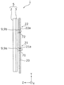
- FIG. 1 is a side view showing a basic configuration of an image display device according to the present disclosure.
- FIG. 2A is a perspective view showing the front side of the image display apparatus according to Embodiment 1.
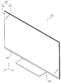
- FIG. 2B is a perspective view showing the back side of the image display device according to Embodiment 1.
- FIG. 3 is a side view showing a configuration outline of the display unit according to the first embodiment.
- FIG. 4 is an exploded perspective view of the image display device according to the first embodiment.
- FIG. 5 is a perspective view showing the configuration of the mounting member according to the first embodiment.
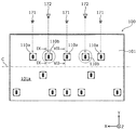
- FIG. 6 is a diagram showing an example of an arrangement layout of a plurality of attachment members according to the first embodiment.
- FIG. 7 is an enlarged perspective view showing the first mounting member and the first opening according to the first embodiment separately.
- FIG. 8 is an enlarged perspective view showing a state in which the first mounting member and the first opening according to Embodiment 1 are fastened with a first screw.
- FIG. 9 is an enlarged perspective view showing the second attachment member and the second opening according to the first embodiment separately.
- FIG. 10 is an enlarged perspective view showing a state in which the second screw penetrating the second opening according to the first embodiment is fixed to the second mounting member.
- FIG. 11 is a view showing an example of another shape of the opening formed in the second opening.
- 12A is a perspective view showing the front side of the image display device according to Embodiment 2.
- FIG. 12B is a perspective view showing the back side of the image display device according to Embodiment 2.
- FIG. 13 is an exploded perspective view of the image display device according to the second embodiment.
- FIG. 14 is an exploded perspective view showing the configuration of the first mounting member and the periphery according to the second embodiment.
- FIG. 15 is an exploded perspective view showing a configuration of a second mounting member according to Embodiment 2 and the periphery thereof.
- FIG. 16 is a partial cross-sectional view showing a configuration of a first mounting member and the periphery according to a second embodiment.
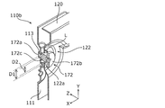
- FIG. 17 is a partial cross-sectional view showing the configuration of a second mounting member according to Embodiment 2 and the periphery thereof.
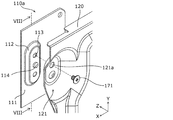
- FIG. 18 is a cross-sectional view showing a state in which a part of the second mounting member exposed from the frame member is inserted into the opening of the base plate.
- an image display apparatus such as a liquid crystal television receiver is provided with a bezel which covers the outer periphery of a display panel, which is, for example, a liquid crystal panel.
- a bezel provided in the image display device for example, a rectangular ring-shaped member is employed as in the front cover in Patent Document 1 mentioned above.
- the display panel when the frame member is not disposed in the image display device, the display panel can not be supported from the outer periphery, and for example, a structure in which the display panel is supported from the back side is adopted. That is, a display unit is configured by arranging, for example, a metal plate on the back side of the display panel, and a stand (which may be a wall hanging unit, hereinafter the same) is directly or indirectly fixed to the metal plate. That is, the stand is fastened to the metal plate forming the back of the display unit with a plurality of screws.
- a stand which may be a wall hanging unit, hereinafter the same
- the metal plate provided on the back side of the display panel is exposed to the outside, which may cause, for example, a problem of insulation measures for the metal plate or an appearance problem. Therefore, it is conceivable to provide not a metal plate but, for example, a glass plate on the back side of the display panel, that is, to form the back side of the display unit with a glass plate. However, in this case, there arises a problem that it is not realistic to fix a stand or the like to a glass plate with a screw.
- the frame member is supported at a plurality of points (such as screws) on a base plate disposed on the back side of the frame member, for example. Therefore, in order to support the display unit including the frame member securely and safely, what kind of support structure should be adopted is a problem.
- the present disclosure has been made based on such findings, and as a result of intensive studies by the inventor of the present application, it has been possible to obtain an idea about the structure of an image display device that can be thinned and is structurally excellent.
- expressions indicating the posture or position of one or more objects may be used. It also includes cases where it is not posture or position.
- parallel means not only completely parallel but also substantially parallel, that is, including, for example, a difference of several% or so. The same is true for expressions such as identical or uniform indicating the relationship between two or more pieces of information or objects.
- the vertical direction is made to coincide with the Y-axis direction
- the longitudinal direction is made to coincide with the Z-axis direction
- the lateral direction is made to coincide with the X-axis direction.
- FIG. 1 is a side view showing a basic configuration of an image display device 1 according to the present disclosure.
- FIG. 1 schematically shows the basic configuration of the image display device 1
- the base plate 20 shows a cross section in the YZ plane passing through the plurality of attachment members 9.
- the surface on the left side (Z-axis plus side) of the display panel 2 is the front surface (plane on which an image is displayed) of the display panel 2, and the direction on the Y-axis plus side is vertically upward.
- An image display apparatus 1 shown in FIG. 1 is an image display apparatus having a configuration common to an image display apparatus 10 according to a first embodiment described later and an image display apparatus 30 according to a second embodiment.
- the image display apparatus 1 according to the present embodiment includes a display panel 2 that displays an image on the front, and a display panel 2 disposed on the back of the display panel 2. And a plurality of mounting members 9 arranged on the support member 3 and a base plate 20 arranged on the back side of the support member 3.
- the base plate 20 has a first opening 21 and a second opening 22.
- the first opening 21 is formed with an opening 21 a through which a fastening member 71 for fastening the first mounting member 9 a which is one of the base plate 20 and the plurality of mounting members 9 passes.
- the second opening 22 is an opening 22a into which the projection 72 provided on the second attachment member 9b which is one of the plurality of attachment members 9 is inserted, and viewed from the projection direction of the projection 72 In this case, the opening 22a larger than the protrusion 72 is formed.
- the display panel 2 is supported from the back side, a frame member for supporting the display panel 2 from the outer periphery in a front view is unnecessary. Therefore, at least the peripheral portion of the portion for displaying an image in the image display device 1 can be thinned.
- the display unit 5 is fixed to the base plate 20 by the first mounting member 9 a disposed on the support member 3.
- the second attachment member 9b disposed in the support member 3 is not in a state of receiving the load of the display unit 5 in a normal state, for example, the attachment portion between the second attachment member 9b and the support member 3 It is hard to produce strength reduction.
- the second mounting member 9b receives the load of the display unit 5 at the time of an abnormality such that one or more of the first mounting members 9a is detached from the supporting member 3, the second mounting member 9b is , Can play a role as a member for supporting the display unit 5.
- the image display device 1 is an image display device 1 that can be thinned and is structurally excellent.
- the 2nd attachment member 9b is located above the 1st attachment member 9a, even if the position of the up-down direction of the 1st attachment member 9a and the 2nd attachment member 9b is the same Alternatively, the first mounting member 9a may be located above the second mounting member 9b.
- Embodiment 1 First, the first embodiment will be described with reference to FIGS. 2A to 10. First, the outline of the configuration of the image display device according to the first embodiment will be described with reference to FIGS. 2A to 4.
- FIG. 2A is a perspective view showing the front side of the image display apparatus 10 according to the first embodiment.
- FIG. 2B is a perspective view showing the back side of the image display device 10 according to the first embodiment.
- FIG. 3 is a side view showing a configuration outline of the display unit 100 according to the first embodiment.
- FIG. 4 is an exploded perspective view of the image display device 10 according to the first embodiment. In FIG. 4, illustration of various electronic circuits, wirings, and the stand 200 and the like is omitted.
- the image display device 10 is, for example, a flat panel display type liquid crystal television receiver.
- the image display device 10 includes a display unit 100 and a stand 200 that supports the display unit 100.
- the display unit 100 includes a display panel 102 for displaying an image on the front surface (surface on the Z-axis plus side), and a support plate 101 disposed on the back side (Z-axis minus side) of the display panel 102 for supporting the display panel 102.
- the support plate 101 is an example of a support member.
- a back cover 190 which is, for example, a resin molded product is disposed on the back side of the display unit 100.
- the back cover 190 covers only a part of the back of the support plate 101 as shown in FIG. 2B. The part is exposed.
- the back cover 190 is comprised by several members, such as a main body and a cover board, in this Embodiment, these several member groups are handled as the back cover 190.
- the display panel 102 included in the display unit 100 is a liquid crystal cell, and as shown in FIG. 3, the optical sheet unit 105 and the conductive sheet are interposed between the display panel 102 and the support plate 101.
- a light plate 103 and a reflector 104 are provided.
- the display panel 102, the optical sheet unit 105, the light guide plate 103, and the reflection plate 104 are fixed to the support plate 101 by an adhesive tape, an adhesive or the like arranged at the peripheral portion. That is, the display unit 100 including the display panel 102, the optical sheet unit 105, the light guide plate 103, the reflection plate 104, and the support plate 101 is treated as one structure in the process of assembling the image display device 10.
- An LED (light emitting diode) unit 150 which is an example of a light source unit is disposed at a position facing the lower end surface of the light guide plate 103 of the display unit 100.
- the light emitted from the LED unit 150 enters the inside of the light guide plate 103 from the lower end face of the light guide plate 103, and enters the display panel 102 through the optical sheet unit 105 disposed on the front surface of the light guide plate 103.
- the optical sheet unit 105 includes one or more optical sheets such as a diffusion sheet or a light collecting sheet. That is, in this embodiment, light for displaying an image is supplied to the display panel 102 which is a liquid crystal cell by an edge light type backlight.
- the LED unit 150 has an elongated substrate 152 along the lower end face of the light guide plate 103 and a plurality of LED elements 151 arranged in parallel on the upper surface of the elongated substrate 152.
- the plurality of LED elements 151 are arranged on one substrate 152, but the LED units 150 are arranged along the lower end face of the light guide plate 103 respectively. May be composed of a plurality of substrates having one or more LED elements 151. That is, the LED unit 150 may be configured by a plurality of LED modules that are separate from one another.
- the LED unit 150 is supported by the light source support member 155 from below.
- the light source support member 155 is a member made of metal such as aluminum, for example, and also functions as a heat dissipation member (heat sink) for releasing the heat generated from the LED unit 150.
- the image display apparatus 10 is provided with a bezel 140 which covers the lower end portion of the front surface of the display panel 102. More specifically, the bezel 140 has a portion covering the lower end portion of the front surface of the display panel 102 and a portion disposed below the light source support member 155.
- the bezel 140 and the light source support member 155 are fixed in the image display device 10 by being directly or indirectly connected to a base plate 120 described later.
- the stand 200 is a leg that allows the image display device 10 to stand on its own, and has a flat stand base 201 and a neck portion 204 provided upright from the stand base 201.
- the neck portion 204 is mechanically connected to the display unit 100, whereby the stand 200 is fixed to the display unit 100.
- the stand 200 is connected to the base plate 120 via the connection member 130 shown in FIG.
- the neck portion 204 is fastened to the connection member 130 with a plurality of screws
- the connection member 130 is fastened to the base plate 120 with a plurality of screws.
- the display unit 100 is fixed to the base plate 120, whereby the stand 200 and the display unit 100 are mechanically connected.
- the stand 200 is illustrated as a member for installing the image display device 10, but instead of the stand 200, for example, the image display device 10 is installed on a wall surface.
- the wall hanging unit may be provided.
- the support plate 101 forming the back surface of the display unit 100 is a glass plate, and as shown in FIG. 2B, when the display unit 100 is viewed from the back side, the upper portion of the support plate 101 and The left and right ends are exposed from the back cover 190. Therefore, when the image display device 10 is observed from the outside, the peripheral portion of the portion displaying the image is thinly recognized, and a gloss peculiar to glass is generated on the back side. That is, thinning of the image display device 10 can be achieved, and the image display device 10 can be made to have an aesthetic appearance.
- the base plate 120 also has a plurality of first openings 121 and second openings 122 provided at positions facing the plurality of attachment members 110.
- the mounting member 110 facing the second opening 122 of the plurality of mounting members 110 plays a different role than the mounting member 110 facing the first opening 121.
- FIGS. 1-10 the configuration of the mounting member 110 and the periphery thereof in the image display device 10 according to the present embodiment will be described with reference to FIGS.
- FIG. 5 is a perspective view showing the configuration of the mounting member 110 according to the first embodiment.
- FIG. 6 is a view showing an example of the layout of the plurality of attachment members 110 according to the first embodiment.
- the two-dot chain line parallel to the X-axis direction in FIG. 6 represents a center line C passing through the center position of the display unit 100 in the vertical direction.
- the mounting member 110 includes a main body portion 111, a boss 112 formed in a convex shape from the main body portion 111, and screw holes 113 and convex portions 114 formed in the boss 112. And.
- the mounting member 110 is a member manufactured by, for example, pressing a metal plate such as aluminum or iron.
- the main body portion 111 is a portion that forms a surface (surface on the Z axis plus side) to be bonded to the back surface 101 a of the support plate 101.
- the adhesive for bonding the main body 111 and the back surface 101a of the support plate 101 is not particularly limited, but, for example, an adhesive having a relatively high adhesive strength and which is less likely to deteriorate with temperature cycles is employed. Ru.
- the mounting member 110 according to the present embodiment can also be used when the member to be fixed is not a glass plate but a metal plate or the like.
- the boss 112 provided at the central portion of the main body portion 111 has a height sufficient to accommodate the tip portion of the screw passing through the screw hole 113.
- the convex portion 114 provided on the boss 112 is a portion that can be used to position a mating member (a base plate 120 in the present embodiment) to be fastened with the mounting member 110 with a screw.
- the first screw 171 is a screw for fastening the base plate 120 and the mounting member 110, and has a head portion 171b and a shaft portion 171a.
- the second screw 172 is a screw that penetrates the base plate 120 and does not fasten the base plate 120 and the attachment member 110.
- the second screw 172 has a head portion 172b, a shaft portion 172a, and a stepped portion 172c provided at the root of the shaft portion 172a. That is, the second screw 172 is, for example, a screw called a "step screw".
- both the shaft portion 171 a of the first screw 171 and the shaft portion 172 a of the second screw 172 can be screwed into the screw hole 113 of the mounting member 110. That is, the outer diameter, the pitch of the screw threads, and the like of the shaft portion 171 a of the first screw 171 and the shaft portion 172 a of the second screw 172 are the same.
- the second screw 172 is used for a part of the attachment members 110 among the plurality of attachment members 110, and for the remaining attachment members 110,
- the first screw 171 is used.
- the twelve attachment members 110 shown in FIG. 6 are common parts, and although the size and shape are the same, the attachment members 110 fastened to the base plate 120 by the first screws 171 are shown. , And the first mounting member 110a. Further, the mounting member 110 to which the second screw 172 is fixed is referred to as a second mounting member 110b.
- two attachment members 110 surrounded by a dotted circle are the second attachment members 110b, and the remaining ten attachment members 110 are the first attachment. It is a member 110a (including one not having a reference numeral).
- the second mounting member 110 b is disposed above the center (center line C) in the vertical direction of the display unit 100.
- the first mounting member 110 a and the second mounting member 110 b thus distinguished are different in structural relationship with the base plate 120.
- the configuration of each of the first mounting member 110a and the second mounting member 110b will be described using FIGS. 7 to 10.
- FIG. 7 the configuration of each of the first mounting member 110a and the second mounting member 110b will be described using FIGS. 7 to 10.
- FIG. 7 is an enlarged perspective view showing the first mounting member 110 a and the first opening 121 according to the first embodiment separately.
- FIG. 7 shows a state in which the first mounting member 110a and the base plate 120 are cut along the YZ plane passing through the line VII-VII in FIG.
- FIG. 8 is an enlarged perspective view showing a state in which the first mounting member 110 a and the first opening 121 according to Embodiment 1 are fastened by the first screw 171.
- FIG. 8 shows a state in which the first mounting member 110a and the base plate 120 are cut along the YZ plane passing through the line VIII-VIII in FIG.
- FIG. 9 is an enlarged perspective view showing the second mounting member 110 b and the second opening 122 according to the first embodiment separately. 9 shows a state in which the second mounting member 110b and the base plate 120 are cut along the YZ plane passing through the line IX-IX in FIG.
- FIG. 10 is an enlarged perspective view showing a state in which the second screw 172 penetrating the second opening 122 according to the first embodiment is fixed to the second mounting member 110 b.
- FIG. 10 shows a state in which the second mounting member 110b and the base plate 120 are cut along the YZ plane passing through the line XX in FIG.
- the first mounting member 110 a is disposed at a position facing the first opening 121 of the base plate 120, and the first mounting member 110 a is moved by the first screw 171 passing through the first opening 121. It is fastened with the first opening 121.
- the first opening 121 is a portion of the base plate 120 in which the opening 121 a through which the first screw 171 passes is formed.
- a hole into which the convex portion 114 of the first mounting member 110 a is inserted is formed below the opening 121 a, and the convex portion 114 is inserted into the hole to form the first opening 121.
- one of the first mounting members 110a is positioned relative to the other.
- the first mounting member 110 a is fixed to the base plate 120 by being fastened to the first opening 121 by the first screw 171, and as a result, the load of the display unit 100 (at least a part of the total load) It will be in the state of receiving).
- the first mounting member 110 a serves as a member for supporting the display unit 100 at normal times.
- the second attachment member 110 b does not have a role to support the display unit 100 at normal times.
- the second attachment member 110b is disposed at a position facing the second opening 122 of the base plate 120, and the second attachment member 110b penetrates the second opening 122.
- the two screws 172 are screwed into the screw holes 113 of the second mounting member 110b.
- the second opening 122 is a portion of the base plate 120 in which an opening 122 a through which the second screw 172 passes is formed.
- the size of the opening 122a is larger than the size of the step portion 172c which is a portion of the second screw 172 which is disposed inside the opening 122a. That is, in the state in which the shaft portion 172a of the second screw 172 is screwed into the screw hole 113 of the second mounting member 110b (the state in which the second screw 172 is fixed to the second mounting member 110b), the step of the second screw 172 There is a gap between the portion 172c and the inner periphery of the opening 122a.
- the stepped portion 172c is an example of a protruding portion provided on the second mounting member.
- the opening 122a and the step 172c are both circular when viewed from the axial direction of the second screw 172 (in the present embodiment, in the Z-axis direction).
- D1 the inner diameter of the opening 122a
- D2 the outer diameter of the stepped portion 172c
- the second mounting member 110 b is not in a state of receiving the load of the display unit 100 at the normal time.
- the second mounting member 110 b does not normally serve as a member for supporting the display unit 100.
- the first mounting member 110 a is peeled from the display unit 100
- the second mounting member 110 b functions as a member for supporting the display unit 100.
- a gap also referred to as “play” exists between the opening 122 a of the second opening 122 and the second screw 172.
- each of the first opening 121 and the second opening 122 has a recessed shape which is recessed toward the display unit 100 as shown in FIGS. 7 to 10.
- the shape of each of the opening 121a and the opening 122a There is no particular limitation on the shape of each of the opening 121a and the opening 122a.
- the portion may be treated as the first opening 121 or the second opening 122.
- a part of the base plate 120 is cut and raised, and the part is treated as the first opening 121 or the second opening 122 by forming the opening 121 a or the opening 122 a in the cut and raised part. It is also good.
- all of the ten attachment members 110 other than the two attachment members 110 treated as the second attachment member 110b are the same as the embodiment shown in FIGS. 7 and 8.
- it may not be connected with the base plate 120.
- the seven attachment members 110 below the center line C may be connected to the base plate 120 via another member (for example, the light source support member 155) fixed to the base plate 120.
- each of the seven attachment members 110 is directly fastened to the other member by the first screw 171.
- the other members are fixed to the base plate 120, the seven mounting members 110 function as members for supporting the display unit 100 at normal times.
- the image display apparatus 10 includes the display panel 102 for displaying an image on the front surface, and the support plate 101 disposed on the back side of the display panel 102 for supporting the display panel 102. And a plurality of mounting members 110 disposed on the support plate 101, and a base plate 120 disposed on the back side of the support plate 101.
- the base plate 120 has a first opening 121 and a second opening 122.
- the first opening 121 is formed with an opening 121 a through which a first screw 171 for fastening the base plate 120 and the first mounting member 110 a which is one of the plurality of mounting members 110 is passed.
- the second opening 122 is an opening 122a into which a protrusion (a step 172c of the second screw 172) provided on the second mounting member 110b which is one of the plurality of mounting members 110 is inserted.
- a protrusion a step 172c of the second screw 172
- an opening 122a larger than the step portion 172c is formed.
- the second mounting member 110b does not receive the load of the display unit 100 in a normal state, the strength reduction of the bonding portion of the support plate 101 with the back surface 101a does not easily occur. Therefore, temporarily, when the second mounting member 110b receives a load of the display unit 100, the display unit 100 is supported when an abnormality occurs such that one or more of the first mounting members 110a are detached from the support plate 101. It can play a role as a member.
- the second screw 172 fixed to the second mounting member 110 b is, for example, below the second opening 122 , And the second screw 172 is caught in the opening 122a. That is, there is a play between the peripheral edge of the second screw 172 and the opening 122a, which causes the movement or the change of the attitude of the display unit 100, thereby causing the structural abnormality in the image display device 10. It can also be recognized by the user. As a result, the user takes action such as requesting repair of the manufacturer of the image display device 10 before complete dropout of the display unit 100 (breaking of the mechanical connection with the stand 200) occurs. Can.
- the image display apparatus 10 is an image display apparatus 10 that can be thinned and is structurally excellent.
- a gap having a width L (L> 0) exists between the head 172 b of the second screw 172 and the surface on which the opening 122 a is formed. . That is, a gap (play) in the axial direction of the second screw 172 also exists between the second screw 172 and the opening 122 a. Therefore, for example, the head 172b of the second screw 172 can prevent the second screw 172 from coming off from the opening 122a, and tilt the display unit 100 in the front-rear direction when an abnormality occurs. Can. That is, the possibility of the user recognizing the occurrence of the structural abnormality is improved.
- each first attachment member 110a may be peeled off from the display unit 100, for example, due to the deterioration of the bonding portion. That is, it can not be said that increasing the number of first attachment members 110 a is sufficient as a fundamental solution for preventing the dropout of the display unit 100.
- the image display device 10 in the image display device 10 according to the present embodiment, at least one combination of the second attachment member 110 b, the second screw 172, and the second opening 122 is disposed, and these elements are It functions as a fail safe mechanism for supporting the display unit 100. That is, the certainty of the fall prevention of the display unit 100 in the image display device 10 is improved.
- the support member for supporting the display panel 102 is the support plate 101 disposed on the back surface side of the display panel 102, and the plurality of attachment members 110 are bonded to the back surface of the support plate 101 There is.
- the display unit 100 is supported by the first mounting member 110 a bonded to the back surface 101 a of the support plate 101. That is, a screw hole for fixing the first mounting member 110 a to the support plate 101 forming the rearmost surface in the display unit 100 is unnecessary. Therefore, as the support plate 101 , for example, a member such as a glass plate that can not substantially form a screw hole can be employed. For example, when a glass plate is employed as the support plate 101 in order to improve the appearance of the image display device 10, the plurality of attachment members 110 can be formed without processing the formation of screw holes in the support plate 101 or the like. It can be fixed to the support plate.
- the display panel 102 is It can be supported from the side. As a result, the peripheral portion of the portion of the image display device 10 that displays the image can be thinned.
- the second attachment member 110 b is disposed above the center (center line C) in the vertical direction of the display unit 100. More specifically, the second attachment member 110 b is disposed such that the step portion 172 c of the second screw 172 is located at or above the center (center line C) in the vertical direction of the display unit 100.
- the display unit 100 is caught in the opening 122a of the second opening 122 at a position above the center in the vertical direction. It is supported by the second screw 172. Therefore, the safety or stability in the state where the display unit 100 is supported by the second screw 172 is improved.
- two second attachment members 110 b are arranged side by side in the left-right direction on the back surface 101 a of the support plate 101.
- the display unit 100 can not be rotated around an axis (Z axis) in the front-rear direction.
- rotation of the display unit 100 around the vertical axis (Y axis) is suppressed.
- a corner that is likely to be broken in the rectangular display unit 100 can be attached to another member in the vicinity of the display unit 100.
- the possibility of interference is reduced. That is, even if the display unit 100 is displaced, damage to the display panel 102 or the support plate 101 made of glass or the like is avoided by peeling off the one or more first attachment members 110 a from the display unit 100. As a result, the possibility of making the image display device 10 difficult to repair is reduced.
- the two second attachment members 110b are disposed at a position where the center of the line connecting the two second attachment members 110b overlaps the center of the display unit 100 in the left-right direction (X-axis direction). It is done. Therefore, for example, when the display unit 100 is supported only at the positions of the two second attachment members 110b, the load applied to the two second attachment members 110b is equalized. That is, since the possibility that an excessive load is applied to one second mounting member 110b is reduced, the stability or safety of the support of the display unit 100 by the two second mounting members 110b is improved.
- the image display device 10 includes the light guide plate 103 disposed between the display panel 102 and the support plate 101;
- the LED unit 150 is disposed at a position facing the lower end surface of the light plate 103, and a light source support member 155 supporting the LED unit 150 from below.
- the light source support member 155 supporting the LED unit 150 that injects light from below is disposed on the lower end surface of the light guide plate 103. That is, the light source support member 155 exists below the lower end of the display unit 100 in terms of structure. Therefore, when the display unit 100 moves downward, the light source support member 155 can function as a member for supporting the display unit 100 from below. Further, for example, when metal is used as a material of the light source support member 155 in order to enhance the heat dissipation by the light source support member 155, the light source support member 155 has relatively high rigidity or strength. Therefore, the effectiveness of the function of supporting the display unit 100 of the light source support member 155 is also improved.
- the image display apparatus 10 includes a bezel 140 which covers the lower end portion of the front surface of the display panel 102.
- the bezel 140 in front of the lower end portion of the display unit 100, the bezel 140 is present. Therefore, if one or more first mounting members 110 a peel off from the display unit 100, the bezel 140 can function as a member for supporting the display unit 100 from the front. For example, when the display unit 100 moves downward, the lower end portion of the display unit 100 is hooked on the bezel 140, so that the display unit 100 can be inclined forward. That is, it is easy for the user to recognize that a structural abnormality has occurred in the image display device 10 while suppressing excessive movement of the display unit 100.
- the bezel 140 In the front view, only the lower end portion of the display unit 100 is covered by the bezel 140. Therefore, by collecting the components such as the LED unit 150 described above below the display unit 100, these components can be hidden by the bezel 140.
- the first attachment member 110 a is formed with a screw hole 113 screwed to the first screw 171 which is a fastening member.
- the second mounting member 110b a screw hole 113 having the same inner diameter as the screw hole 113 of the first mounting member 110a is formed, into which the second screw 172 forming the projecting portion is screwed.
- the mounting member 110 shown in FIG. 5 is used as the first mounting member 110a and the second mounting member 110b. That is, there is no need to separately manufacture the first mounting member 110a for fixing the display unit 100 to the base plate 120 and the second mounting member 110b as a locking means when the first mounting member 110a is peeled off. This is advantageous from the viewpoint of improving the manufacturing efficiency of the image display device 10 or suppressing the manufacturing cost.
- the protruding portion provided on the second mounting member 110b is formed at the root of the shaft portion 172a and the shaft portion 172a screwed into the screw hole 113 formed on the second mounting member 110b.
- Embodiment 1 has been described as an example of the technology disclosed in the present application.
- the technology in the present disclosure is not limited to this, and is also applicable to embodiments in which changes, replacements, additions, omissions, and the like are appropriately made.
- each component described in the first embodiment can be combined to make a new embodiment. Therefore, other embodiments will be exemplified below.
- the shape and size of the opening 122 a of the second opening 122 are not limited to the shapes and sizes shown in FIGS. 9 and 10.
- the shape of the opening 122a does not have to be circular, but may be long in a predetermined direction.
- FIG. 11 is a view showing an example of another shape of the opening formed in the second opening 122.
- the head 172 b of the second screw 172 is represented by a dotted circle so that the structural relationship between the opening 122 b formed in the second opening 122 and the second screw 172 can be clearly understood.
- Stepped portion 172c located inside 122b is represented by a hatched circle.
- the opening 122 b formed in the second opening 122 shown in FIG. 11 is longer in the vertical direction than in the horizontal direction. That is, the opening 122b has a vertically long shape.
- a gap between the step portion 172c and the inner periphery of the opening 122b exists at least below the step portion 172c.
- the second screw 172 is guided by the opening 122b, whereby the display unit 100 is moved.
- the movement direction of is restricted to the direction immediately below (the direction of the Y axis minus side). As described above, it is possible to control the moving direction of the display unit 100 according to the shape of the opening 122 b.
- the second screw 172 has a head portion 172 b larger than the opening 122 a formed in the second opening 122, but this is not essential.
- the head 172b is smaller than the opening 122a, since the moving direction of the display unit 100 is mainly downward, there is a high possibility that the head 172b is caught at the lower end of the opening 122a.
- the second screw 172 does not have the head portion 172b, if the axial length of the step portion 172c is relatively long, the step portion 172c moves from the opening 122a when the display unit 100 moves. The chance of getting out is low.
- the second screw 172 has the step portion 172c, and for example, a rod having the same diameter as the shaft portion 172a of the second screw 172 may be disposed at the position of the step portion 172c.
- the protrusion part provided in the 2nd attachment member 110b may be implement
- a convex portion of a size that can be inserted into the opening 122a of the second opening 122 is formed in the second attachment member 110b, and a head larger than the opening 122a is formed at the tip of the convex portion passing through the opening 122a. Attach the screw with.
- the same function as the second screw 172 can be carried by the convex portion integrally provided on the second attachment member 110b.
- a flat protrusion may be formed by cutting and raising a part of the second mounting member 110 b which is a plate-like member.
- the protrusion may be prevented from coming out of the opening 122 a of the second opening 122 by bending the tip of the cut and raised metal piece downward.
- the number of second attachment members 110 b among the twelve attachment members 110 shown in FIG. 6 is not limited to two, and at least one second attachment member 110 b is bonded to the support plate 101. Just do it. Also, for example, one or more second mounting members 110 b may be bonded to a region below the center line C in the back surface 101 a of the support plate 101.
- the number of attachment members 110 bonded to the back surface 101 a of the support plate 101 is not limited to twelve.
- the number of attachment members 110 provided in the image display apparatus 10 and how many of them are disposed as the first attachment member 110 a for example, the weight of the display unit 100, the lifetime of other components such as the display panel 102 And, in consideration of the durability and the like of the adhesive used for bonding the mounting member 110, it may be determined as appropriate.
- the arrangement positions of the one or more first attachment members 110a and the one or more second attachment members 110b may be appropriately determined in consideration of, for example, the gravity center position of the display unit 100 or the size and shape of the base plate 120. Just do it.
- first mounting member 110a and the second mounting member 110b are common members, the first mounting member 110a and the second mounting member 110b have different shapes and sizes. It may be.
- the second mounting member 110b which has a role as a locking means for emergency, has a screw hole 113 whose inside diameter is larger than the screw hole 113 of the first mounting member 110a so that a screw having a larger diameter is fixed. You may have.
- each of the first attachment member 110 a and the second attachment member 110 b may have a plurality of screw holes 113 so that a plurality of screws can be attached.
- the type of the display panel 102 included in the image display device 10 is not limited to the liquid crystal cell.
- an organic EL (Electroluminescence) display panel may be adopted as the display panel 102.
- the display unit 100 includes, for example, an organic EL display panel and a support plate 101 attached to the back of the organic EL display panel.
- Second Embodiment Second Embodiment A second embodiment will now be described with reference to FIGS. 12A-17. First, the outline of the configuration of the image display device according to the second embodiment will be described with reference to FIGS. 12A to 13.
- FIG. 12A is a perspective view showing the front side of the image display device 30 according to Embodiment 2.
- FIG. 12B is a perspective view showing the back side of the image display device 30 according to Embodiment 2.
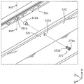
- FIG. 13 is an exploded perspective view of the image display device 30 according to the second embodiment. In FIG. 13, illustration of various electronic circuits, wirings, a stand 400 and the like is omitted.
- the image display device 30 is, for example, a flat panel display type liquid crystal television receiver.
- the image display device 30 includes a display unit 300 and a stand 400 that supports the display unit 300.
- the display unit 300 has a display panel 302 for displaying an image on the front surface (surface on the Z-axis plus side), and a frame member 301 attached to the periphery of the back surface of the display panel 302.
- the frame member 301 is an example of a support member.
- a base plate 320 is disposed on the back side of the frame member 301.
- a back cover 390 which is a resin molded product, for example, is disposed on the back side of the base plate 320, and the back cover 390 covers only a part of the back of the base plate 320, as shown in FIG. 12B. Exposed.
- the back cover 390 is constituted by a plurality of members such as a main body and a lid plate, in the present embodiment, the plurality of member groups are treated as the back cover 390.
- the display panel 302 included in the display unit 300 is a liquid crystal cell
- the display unit 300 further includes optical members such as an optical sheet unit and a light guide plate.
- the LED unit 350 which is an example of a light source part is arrange
- light for image display is supplied to the display panel 302 which is a liquid crystal cell by an edge light type backlight as in the first embodiment. Details of the display unit 300 will be described later with reference to FIGS. 16 and 17.
- the LED unit 350 includes an elongated substrate along the lower end face of the light guide plate 303 and a plurality of LED elements arranged in parallel on the upper surface of the substrate.
- the image display device 30 is provided with a bezel 340 which covers the lower end portion of the front surface of the display panel 302 and the LED unit 350.
- the bezel 340 is fixed in the image display device 30 by being directly or indirectly connected to the base plate 320.
- the stand 400 is a leg that allows the image display device 30 to stand on its own, and is mechanically connected to the base plate 320.
- the image display device 30 may include, for example, a wall mounting unit for installing the image display device 30 on a wall surface, instead of the stand 400.
- the frame member 301 for supporting the display panel 302 is, for example, a member made of resin, and is arranged along four sides (upper side, left side, right side, and lower side) on the back surface of the display panel 302 in this embodiment.
- the frame member 301 may be a rectangular ring-shaped member in which the portions corresponding to the four sides are integrally formed. Further, the rectangular annular frame member 301 may be formed by connecting two or more members with a screw or the like.
- the frame member 301 is attached to the base plate 320 by a plurality of screws. More specifically, as shown in FIG. 13, the base plate 320 has a plurality of first openings 321 disposed along the periphery and a second opening 322 disposed one on the left and one on the right. Mounting members 310 are disposed in the frame member 301 at positions facing the first opening 321 and the second opening 322, respectively.
- the first screw 371 is inserted into the first opening 321 of the base plate 320, and the first screw 371 is screwed to the mounting member 310 at the opposite position.
- the second screw 372 is inserted through the second opening 322 of the base plate 320, and the second screw 372 is screwed into the mounting member 310 at the opposite position.
- the frame member 301 supporting the display panel 302 is fixed to the base plate 320.
- first screws 371 are denoted by reference numeral 371 for simplicity of illustration, but they are at the same position as the four first screws 371 in the Z-axis direction. All the screws other than the two second screws 372 are the first screws 371. Further, the first opening 321 and the mounting member 310 are disposed at positions facing the respective first screws 371 in the Z-axis direction.
- the mounting member 310 facing the second opening 322 of the plurality of mounting members 310 plays a different role than the mounting member 310 facing the first opening 321.
- the configuration of the attachment member 310 and the periphery thereof in the image display device 30 according to the present embodiment will be described with reference to FIGS. 14 to 17.
- FIG. 14 is an exploded perspective view showing the configuration of the first mounting member 310a according to Embodiment 2 and the periphery thereof. Specifically, FIG. 14 shows the configuration of the mounting member 310 disposed within the dotted rectangle XIV in FIG. 13 and the periphery thereof.
- FIG. 15 is an exploded perspective view showing the configuration of the second mounting member 310 b according to Embodiment 2 and the periphery thereof. Specifically, FIG. 15 shows the configuration of the attachment member 310 disposed within the dotted rectangle XV in FIG. 13 and the periphery thereof.
- the components (display panel 302 etc.) other than the frame member 301 in the display unit 300 are not shown.
- FIG. 16 is a partial cross-sectional view showing the configuration of the first mounting member 310a according to Embodiment 2 and the periphery thereof. Specifically, FIG. 16 is a view schematically showing a partial cross section of the image display device 30 taken along line XVI-XVI in FIG.
- FIG. 17 is a partial cross-sectional view showing the configuration of the second mounting member 310b according to Embodiment 2 and the periphery thereof. Specifically, FIG. 17 is a view schematically showing a partial cross section of the image display device 30 taken along line XVII-XVII in FIG.
- the plurality of mounting members 310 disposed on the frame member 301 include a first mounting member 310a and a second mounting member 310b.
- the first mounting member 310 a and the second mounting member 310 b are, for example, metal nuts, and the first mounting member 310 a is screwed with the first screw 371, and the second mounting member 310 b is screwed with the second screw 372.
- the frame member 301 is provided with an arrangement hole 301a for arranging the first attachment member 310a and an arrangement hole 301b for arranging the second attachment member 310b.
- the first attachment member 310a when assembling the image display device 30, for example, the first attachment member 310a is inserted into the arrangement hole 301a while being heated and pressed. Thus, the inner peripheral surface of the arrangement hole 301a is melted, and as a result, the inner peripheral surface and the outer peripheral surface of the first mounting member 310a are welded.
- the second attachment member 310b is inserted into the arrangement hole 301b while being heated and pressurized. Thus, the inner peripheral surface of the arrangement hole 301b is melted, and as a result, the inner peripheral surface and the outer peripheral surface of the first mounting member 310a are welded.
- the first mounting member 310 a and the second mounting member 310 b are parts called, for example, an outsert nut, and are parts fixed later to the resin frame member 301.
- irregularities are formed by knurling so as to be firmly fixed to the inner peripheral surfaces of the arrangement holes 301a and 301b.
- the frame member 301 provided with the attachment member 310 may be produced by insert molding.
- the mounting member 310 may be fixed to the frame member 301 by press-fitting the mounting member 310 into the arrangement hole of the frame member 301.
- the mounting member 310 may be fixed to the frame member 301 by an adhesive.
- the mounting member 310 may be fixed to the frame member 301 by screwing the mounting member 310 having a screw thread on the outer peripheral surface into the screw hole of the frame member 301.
- the first screw 371 is a screw for fastening the base plate 320 and the first attachment member 310a, and has a head 371b and a shaft 371a.
- the second screw 372 is a screw that penetrates the base plate 320 and does not fasten the base plate 320 and the second attachment member 310 b.
- the second screw 372 has a head 372b, a shaft 372a, and a step 372c provided at the root of the shaft 372a. That is, the second screw 372 is, for example, a screw called a "step screw".
- the shaft portion 371a of the first screw 371 passes through the opening 321a provided in the first opening 321 of the base plate 320 and is screwed into the first attachment member 310a.
- a first opening that is a part of the base plate 320 between the head 371 b of the first screw 371 and the first attachment member 310 a (frame member 301) 321 is caught.
- a plurality of first screws 371 for fastening the base plate 320 and the frame member 301 are disposed in the image display device 30, whereby the frame member 301 is placed against the base plate 320. It is fixed.
- the display panel 302 is attached to the frame member 301 via an adhesive member 306 which is, for example, a double-sided tape. Further, on the back side of the display panel 302, optical members (optical sheet unit 305, light guide plate 303, and reflection plate 304) which the backlight unit has are disposed, and these optical members are shown in FIGS. It is supported by the frame member 301 or the base plate 320 at parts other than the positions shown.
- the first mounting member 310 a is fixed to the base plate 320 by being fastened to the first opening 321 by the first screw 371, whereby the base plate 320 is fixed to the frame member 301.
- the first mounting member 310a is in a state of receiving the load of the display unit 300 (including at least a part of the total load) at normal times.
- the first attachment member 310 a serves as a member for supporting the display unit 300 at normal times.
- the second attachment member 310 b does not normally play a role in supporting the display unit 300.
- the second attachment member 310 b is disposed at a position facing the second opening 322 of the base plate 320.
- the shaft portion 372a of the second screw 372 is screwed into the second mounting member 310b.
- the size of the opening 322a is larger than the size of the step portion 372c, which is a portion of the second screw 372 disposed inside the opening 322a. That is, in a state in which the shaft portion 372a of the second screw 372 is screwed with the second attachment member 310b, a gap (in the radial direction) is formed between the step portion 372c of the second screw 372 and the inner peripheral surface of the opening 322a. There is a gap).
- the stepped portion 372c is an example of a protruding portion provided on the second mounting member.
- the opening 322a and the step 372c are both circular when viewed from the axial direction of the second screw 372 (in the present embodiment, in the Z-axis direction).
- D3 the inside diameter of the opening 322a
- D4 the outside diameter of the stepped portion 372c
- D3 D4> D4.
- a gap M a gap having a width M (hereinafter referred to as “a gap M”) exists between the head 372 b of the second screw 372 and the surface on which the opening 322 a is formed.
- the second mounting member 310 b is not in a state of receiving the load of the display unit 300 at the normal time.
- the second mounting member 310 b does not normally serve as a member for supporting the display unit 300.
- the second attachment member 310 b functions as a member for supporting the display unit 300.
- a gap (play) exists between the opening 322 a of the second opening 322 and the second screw 372.
- the second attachment member 310 b when the second attachment member 310 b is in a state of supporting the display unit 300, it is possible to cause the movement or the change of the attitude of the display unit 300. Thereby, the user can be made to recognize that a structural abnormality has occurred in the image display device 30.
- the image display apparatus 30 includes the display panel 302 for displaying an image on the front surface, and the frame member 301 disposed on the back side of the display panel 302 for supporting the display panel 302. And a plurality of mounting members 310 disposed on the frame member 301, and a base plate 320 disposed on the back side of the frame member 301.
- the base plate 320 has a first opening 321 and a second opening 322. In the first opening 321, an opening 321a is formed through which a first screw 371 for fastening the base plate 320 and the first attachment member 310a which is one of the plurality of attachment members 310 passes.
- the second opening 322 is an opening 322a into which a protrusion (a step 372c of the second screw 372) provided on the second attachment member 310b which is one of the plurality of attachment members 310 is inserted.
- a protrusion a step 372c of the second screw 372
- an opening 322 a larger than the step 372 c is formed.
- the second mounting member 310 b does not receive the load of the display unit 300 under normal conditions, the reduction in strength of the mounting portion with respect to the frame member 301 hardly occurs. Therefore, temporarily, the second attachment member 310b receives the load of the display unit 300 at the time of occurrence of abnormality that one or more of the first attachment members 310a is detached from the frame member 301 due to aged deterioration of the frame member 301 or the like. In the state, it can play a role as a member for supporting the display unit 300.
- the second screw 372 fixed to the second mounting member 310 b is, for example, below the second opening 322.
- the second screw 372 is caught in the opening 322a. That is, there is a play between the peripheral edge of the second screw 372 and the opening 322a, which causes the movement or the change of the attitude of the display unit 300, thereby causing the structural abnormality of the image display device 30. It can also be recognized by the user. As a result, the user takes action, for example, requesting a manufacturer of the image display device 30 for repair before complete removal of the display unit 300 (breaking of the mechanical connection with the base plate 320) occurs. Can.
- the image display apparatus 30 according to the present embodiment is an image display apparatus 30 that can be thinned and is structurally excellent.
- two second attachment members 310 b are arranged side by side in the left-right direction on the frame member 301.
- the display unit 300 can be prevented from rotating around an axis (Z axis) in the front-rear direction.
- rotation of the display unit 300 around the vertical axis (Y axis) is suppressed.
- the corner of the display panel 302 that is easily damaged in the rectangular display unit 300 is in the vicinity of the display unit 300.
- the possibility of interfering with certain other components is reduced. That is, when the one or more first attachment members 310 a are detached from the display unit 300, the display panel 302 is not damaged even if the display unit 300 is displaced. As a result, the possibility of difficulty in repairing the image display device 30 is reduced.
- the two second attachment members 310b are disposed at a position where the center of the line connecting the two second attachment members 310b overlaps the center of the display unit 300 in the left-right direction (X-axis direction). It is done. Therefore, for example, when the display unit 300 is supported only at the positions of the two second attachment members 310b, the load applied to the two second attachment members 310b is equalized. That is, since the possibility of applying an excessive load to one second attachment member 310b is reduced, the stability or safety of the support of the display unit 300 by the two second attachment members 310b is improved.
- the image display device 30 includes a bezel 340 that covers the lower end portion of the front surface of the display panel 302.
- the bezel 340 in front of the lower end portion of the display unit 300, the bezel 340 is present. Therefore, if one or more of the first mounting members 310a are detached from the display unit 300, the bezel 340 can function as a member for supporting the display unit 300 from the front. For example, when the display unit 300 moves downward, the lower end portion of the display unit 300 is hooked on the bezel 340, so that the display unit 300 can be inclined forward. That is, it is easy for the user to recognize that a structural abnormality has occurred in the image display device 30 while suppressing excessive movement of the display unit 300.
- the support member for supporting the display panel 302 from the back surface side is the frame member 301 attached to the peripheral edge of the back surface of the display panel 302, and the plurality of attachment members 310 are welded to the frame member 301. ing.
- mechanical bonding between the frame member 301 and the mounting member 310 is achieved by adopting welding as a method of fixing the mounting member 310, which is a metal nut, to the resin-made frame member 301, for example. I can strengthen my strength. As a result, the mounting member 310 can be firmly fixed to the mounting member 310.
- the mounting member 310 is an outsert nut embedded in the frame member 301. Therefore, the mounting member 310 can be obtained or manufactured relatively easily. Further, the mounting member 310 made of resin can be fixed to the frame member 301 by a relatively easy process. Further, it is also possible to further strengthen the mechanical coupling force between the frame member 301 and the mounting member 310 by knurling or the like on the outer peripheral surface of the mounting member 310.
- the image display device 30 includes the back cover 390 that covers a part of the back surface of the base plate 320.
- the second opening 322 is disposed in the base plate 320 at a position covered by the back cover 390 (see FIG. 13).
- a gap is formed between the second screw 372 and the opening 322a of the second opening 322 is covered by the back cover 390, so, for example, foreign matter such as dust or dirt in the space Invasion is suppressed.
- the gap between the second screw 372 and the opening 322a which is provided for the safety of the image display device 30, is hidden by the back cover 390, the user may be anxious to see the gap.
- the protrusion provided on the second mounting member 310b is formed at the root of the shaft 372a screwed into the screw hole formed on the second mounting member 310b, and at the root of the shaft 372a.
- a step portion 372c in a stepped screw (second screw 372) having a step portion 372c is formed in a size larger than that of the step 372c when viewed from the axial direction of the shaft 372a, and the step 372c is inserted.
- Embodiment 2 has been described as an example of the technology disclosed in the present application.
- the technology in the present disclosure is not limited to this, and is also applicable to embodiments in which changes, replacements, additions, omissions, and the like are appropriately made.
- each component described in the second embodiment can be combined to make a new embodiment. Therefore, other embodiments will be exemplified below.
- the shape and size of the opening 322a of the second opening 322 are not limited to the shape and size shown in FIG.
- the shape of the opening 322a does not have to be circular, but may be elongated in a predetermined direction.
- the opening 322 a of the second opening 322 may be longer in the vertical direction than in the horizontal direction.
- the display unit 300 tries to move by dismounting the one or more first attachment members 310a from the display unit 300, the second screw 372 is guided by the opening 322a, whereby the display unit 300 is moved.
- the movement direction of is restricted to the direction immediately below (the direction of the Y axis minus side).
- the head portion 372b of the second screw 372 may be smaller than the opening 322a. Even in this case, since the moving direction of the display unit 300 is mainly downward, there is a high possibility that the head portion 372b is caught at the lower end of the opening 322a. Further, even if the second screw 372 does not have the head portion 372b, if the axial length of the step portion 372c is relatively long, the step portion 372c passes from the opening 322a when the display unit 300 moves. The chance of getting out is low.
- the second screw 372 has the step 372c.
- a rod having the same diameter as the shaft 372a of the second screw 372 may be disposed at the position of the step 372c.
- the protruding portion provided on the second attachment member 310 b may be realized by other than the second screw 372.
- the second attachment member 310b is formed with a convex portion of a size that can be inserted into the opening 322a of the second opening 322, and a head larger than the opening 322a at the tip of the convex portion passing through the opening 322a Attach the screw with.
- the same function as the second screw 372 can be carried by the convex portion integrally provided on the second attachment member 310b.
- a part of the second mounting member 410b which is an outsert nut may be exposed from the frame member 301, and the exposed part may be inserted into the opening 322a.
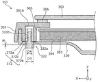
- FIG. 18 is a cross-sectional view showing a state in which a part of the second attachment member 410b exposed from the frame member 301 is inserted into the opening 322a.
- the position of the cross section in FIG. 18 conforms to the position of the cross section shown in FIG.
- the second attachment member 410b relatively long in the axial direction is disposed in the disposition hole 301b of the frame member 301, and a portion of the second attachment member 410b is exposed from the frame member 301 Do. Furthermore, the exposed portion (exposed portion) of the second mounting member 410b is inserted into the opening 322a that the second opening 322 of the base plate 320 has, and the second mounting member 410b does not have the stepped portion of the second screw 472. Screw in the shaft portion 472a. In this case, as shown in FIG. 18, even if the entire shaft portion 472a is screwed into the second mounting member 410b, the head portion 472b abuts on the end surface of the exposed portion of the second mounting member 410b. , Does not abut the surface where the opening 322a is formed. Further, the outer diameter D4 of the exposed portion of the second mounting member 410b is smaller than the inner diameter D3 of the opening 322a.
- a radial gap is formed between the exposed portion of the second attachment member 410b and the inner peripheral surface of the opening 322a, and an axial direction is formed between the head 472b and the surface on which the opening 322a is formed.
- a gap of width N (a gap N) is formed.
- the image display device 30 includes the two second attachment members 310b, but the number of second attachment members 310b is not limited to two, and at least one second attachment member 310b. May be fixed to the frame member 301.
- the number of first attachment members 310 a fixed to the frame member 301 is not particularly limited. That is, the number and the arrangement position of the first attachment member 310a and the second attachment member 310b may be appropriately determined according to, for example, the size or weight of the display unit 300.
- the second attachment member 310 b may be disposed above the center in the vertical direction of the display unit 300.
- the display unit 300 is caught in the opening 322a of the second opening 322 at a position above the center in the vertical direction. It is supported by a second screw 372. Therefore, the safety or stability in a state where the display unit 300 is supported by the second screw 372 is improved.
- the type of the display panel 302 included in the image display device 30 is not limited to the liquid crystal cell.
- an organic EL display panel may be adopted as the display panel 302.
- the display unit 300 includes, for example, an organic EL display panel and a frame member 301 attached to the back of the organic EL display panel.
- the present disclosure is applicable to an image display device for displaying an image. Specifically, the present disclosure is applicable to television receivers, monitor displays, digital signage, and the like.
Landscapes
- Physics & Mathematics (AREA)
- Nonlinear Science (AREA)
- Mathematical Physics (AREA)
- Chemical & Material Sciences (AREA)
- Crystallography & Structural Chemistry (AREA)
- General Physics & Mathematics (AREA)
- Optics & Photonics (AREA)
- Engineering & Computer Science (AREA)
- Multimedia (AREA)
- Signal Processing (AREA)
- Devices For Indicating Variable Information By Combining Individual Elements (AREA)
- Liquid Crystal (AREA)
Abstract
画像表示装置(1)は、表示パネル(2)及び表示パネル(2)を支持する支持部材(3)を有する表示ユニット(5)と、支持部材(3)に配置された複数の取付部材(9)と、支持部材(3)の背面側に配置されたベースプレート(20)とを備える。ベースプレート(20)は、第一開口部(21)と第二開口部(22)とを有する。第一開口部(21)には、ベースプレート(20)と、第一取付部材(9a)とを締結する締結部材(71)が貫通する開口(21a)が形成されている。第二開口部(22)には、第二取付部材(9b)に設けられた突出部(72)が挿入される開口(22a)であって、突出部(72)の突出方向から見た場合に、突出部(72)より大きな開口(22a)が形成されている。
Description
本開示は、画像を表示する表示パネルを備える画像表示装置に関する。
特許文献1は、画像を表示するパネルと、パネルを前面に支持したシャーシと、シャーシの背面に固定された複数の回路基板と、これらを内部に納めるフロントカバーおよびバックカバーとを備える画像表示装置を開示する。
本開示は、薄型化が可能であり、かつ、構造的に優れた画像表示装置を提供する。
本開示における画像表示装置は、前面に画像を表示する表示パネル、及び、前記表示パネルの背面側に配置された、前記表示パネルを支持する支持部材を有する表示ユニットと、前記支持部材に配置された複数の取付部材と、前記支持部材の背面側に配置されたベースプレートとを備え、前記ベースプレートは、前記ベースプレート、及び、前記複数の取付部材のうちの1つである第一取付部材を締結する締結部材が貫通する開口が形成された第一開口部と、前記複数の取付部材のうちの1つである第二取付部材に設けられた突出部が挿入される開口であって、前記突出部の突出方向から見た場合に、前記突出部より大きな開口が形成された第二開口部とを有する。
本開示によれば、薄型化が可能であり、かつ、構造的に優れた画像表示装置を提供することができる。
本願発明者らは、従来の画像表示装置に関し、以下の問題が生じることを見出した。従来、液晶テレビジョン受像機等の画像表示装置では、例えば液晶パネルである表示パネルの外周を覆うベゼルが備えられている。画像表示装置が備えるベゼルとしては、例えば上記特許文献1におけるフロントカバーのように、矩形環状の部材が採用される。
しかしながら、近年では、画像表示装置に対して薄型化が求められており、本願発明者らは、その要求に応えるために、表示パネルの周囲を囲む枠部材を持たない画像表示装置の構造についての検討を進めた。
具体的には、画像表示装置に枠部材を配置しない場合、表示パネルを外周から支えることができないため、例えば、表示パネルを背面側から支持する構造が採用される。つまり、表示パネルの背面側に例えば金属板を配置することで表示ユニットを構成し、その金属板に、例えばスタンド(壁掛ユニットでもよい、以下同じ)を直接的または間接的にネジで固定する。つまり、表示ユニットの背面を形成する金属板に、スタンドが複数のネジで締結される。これにより、表示パネルの周囲が枠で囲まれていない構造の画像表示装置が実現される。
しかしながらこの場合、表示パネルの背面側に設けられた金属板が外部に露出するため、例えば、金属板についての絶縁対策の問題、または、外観上の問題が生じ得る。そこで、金属板ではなく、例えばガラス板を表示パネルの背面側に設けること、つまり、表示ユニットの背面をガラス板で形成することが考えられる。しかし、この場合、ガラス板に対してスタンド等をネジで固定することは現実的ではないという問題が生じる。
また、例えば、表示パネルの背面周縁に取り付けられた枠部材で表示パネルを支持することでも、表示パネルの周囲が枠で囲まれていない構造の画像表示装置を実現することができる。しかしながらこの場合、その枠部材は、例えば、枠部材の背面側に配置されたベースプレートに複数の点(ネジ等)で支持される。従って、枠部材を含む表示ユニットを、確実かつ安全に支持するためには、どのような支持構造を採用すべきかが問題となる。
本開示は、このような知見に基づいてなされたものであり、本願発明者が鋭意検討した結果、薄型化が可能であり、かつ、構造的に優れた画像表示装置の構造についての着想を得た。
以下、適宜図面を参照しながら、実施の形態を説明する。但し、必要以上に詳細な説明は省略する場合がある。例えば、既によく知られた事項の詳細説明や実質的に同一の構成に対する重複説明を省略する場合がある。これは、以下の説明が不必要に冗長になるのを避け、当業者の理解を容易にするためである。また、図面は、本開示に係る画像表示装置の構成をわかりやすく示すために、適宜強調、省略、または比率の調整を行った模式的な図を含んでおり、実際の形状、位置関係、及び比率とは異なる場合がある。
また、以下の実施の形態の説明及び請求の範囲において、平行または中央などの、1以上の物体の姿勢または位置等を示す表現が用いられる場合があるが、これらの表現は、厳密にはその姿勢または位置等ではない場合も含む。例えば、平行とは、完全に平行であることを意味するだけでなく、実質的に平行である場合、すなわち、例えば数%程度の差異を含むことも意味する。2以上の情報または物体の関係を示す、同一または均一等の表現についても同じである。
なお、本願発明者らは、当業者が本開示を十分に理解するために添付図面及び以下の説明を提供するのであって、これらによって請求の範囲に記載の主題を限定することを意図するものではない。
また、以下の実施の形態において、説明の便宜上、上下方向をY軸方向と一致させ、前後方向をZ軸方向と一致させ、左右方向(横方向)をX軸方向と一致させているが、これら対応付けは、本開示に係る画像表示装置の製造時または使用時における姿勢を限定するものではない。また、以下の説明において、例えば、X軸プラス側とは、X軸の矢印方向側を示し、X軸マイナス側とは、X軸プラス側とは反対側を示す。Y軸方向及びZ軸方向についても同様である。
(本開示に係る画像表示装置の基本構成)
まず、図1を用いて、本開示に係る画像表示装置の基本構成を説明する。図1は、本開示に係る画像表示装置1の基本構成を示す側面図である。なお、図1では、画像表示装置1の基本構成が模式的に示されており、ベースプレート20は、複数の取付部材9を通るYZ平面における断面が図示されている。また、図1において、表示パネル2の左側(Z軸プラス側)の面が、表示パネル2の前面(画像を表示する面)であり、Y軸プラス側の方向が鉛直上方である。
まず、図1を用いて、本開示に係る画像表示装置の基本構成を説明する。図1は、本開示に係る画像表示装置1の基本構成を示す側面図である。なお、図1では、画像表示装置1の基本構成が模式的に示されており、ベースプレート20は、複数の取付部材9を通るYZ平面における断面が図示されている。また、図1において、表示パネル2の左側(Z軸プラス側)の面が、表示パネル2の前面(画像を表示する面)であり、Y軸プラス側の方向が鉛直上方である。
図1に示す画像表示装置1は、後述する実施の形態1に係る画像表示装置10及び実施の形態2に係る画像表示装置30に共通する構成を有する画像表示装置である。具体的には、本実施の形態に係る画像表示装置1は、図1に示すように、前面に画像を表示する表示パネル2、及び、表示パネル2の背面側に配置された、表示パネル2を支持する支持部材3を有する表示ユニット5と、支持部材3に配置された複数の取付部材9と、支持部材3の背面側に配置されたベースプレート20とを備える。ベースプレート20は、第一開口部21と第二開口部22とを有する。第一開口部21には、ベースプレート20、及び、複数の取付部材9のうちの1つである第一取付部材9aを締結する締結部材71が貫通する開口21aが形成されている。第二開口部22には、複数の取付部材9のうちの1つである第二取付部材9bに設けられた突出部72が挿入される開口22aであって、突出部72の突出方向から見た場合に、突出部72より大きな開口22aが形成されている。
この構成によれば、表示パネル2は背面側から支持されるため、表示パネル2を、正面視における外周から支持する枠部材が不要である。そのため、少なくとも、画像表示装置1において画像を表示する部分の周縁部の薄型化が図られる。また、表示ユニット5は、支持部材3に配置された第一取付部材9aによってベースプレート20に固定される。また、支持部材3に配置された第二取付部材9bは、通常時においては、表示ユニット5の荷重を受けない状態であるため、例えば、第二取付部材9bと支持部材3との取り付け部分の強度低下が生じ難い。そのため、仮に、1以上の第一取付部材9aが支持部材3から外れる、という異常発生時において、第二取付部材9bが表示ユニット5の荷重を受ける状態となった場合、第二取付部材9bは、表示ユニット5を支持する部材としての役割を果たすことができる。
このように、本実施の形態に係る画像表示装置1は、薄型化が可能であり、かつ、構造的に優れた画像表示装置1である。なお、図1では、第二取付部材9bが第一取付部材9aよりも上方に位置しているが、第一取付部材9a及び第二取付部材9bの上下方向の位置は、同一であってもよく、また、第一取付部材9aが第二取付部材9bよりも上方に位置していてもよい。
上記の基本構成を有する画像表示装置1のより具体的な例を、以下に、実施の形態1及2として説明する。
(実施の形態1)
まず、図2A~図10を用いて実施の形態1を説明する。まず、図2A~図4を用いて、実施の形態1に係る画像表示装置の構成概要について説明する。
まず、図2A~図10を用いて実施の形態1を説明する。まず、図2A~図4を用いて、実施の形態1に係る画像表示装置の構成概要について説明する。
[1-1.画像表示装置の全体構成]
図2Aは、実施の形態1に係る画像表示装置10の正面側を示す斜視図である。図2Bは、実施の形態1に係る画像表示装置10の背面側を示す斜視図である。図3は、実施の形態1に係る表示ユニット100の構成概要を示す側面図である。図4は、実施の形態1に係る画像表示装置10の分解斜視図である。なお、図4では、各種の電子回路、配線、及び、スタンド200等の図示は省略されている。
図2Aは、実施の形態1に係る画像表示装置10の正面側を示す斜視図である。図2Bは、実施の形態1に係る画像表示装置10の背面側を示す斜視図である。図3は、実施の形態1に係る表示ユニット100の構成概要を示す側面図である。図4は、実施の形態1に係る画像表示装置10の分解斜視図である。なお、図4では、各種の電子回路、配線、及び、スタンド200等の図示は省略されている。
図2A及び図2Bに示すように、画像表示装置10は、例えばフラットパネルディスプレイ型の液晶テレビジョン受像機である。画像表示装置10は、表示ユニット100と、表示ユニット100を支持するスタンド200とを備えている。表示ユニット100は、前面(Z軸プラス側の面)に画像を表示する表示パネル102と、表示パネル102の背面側(Z軸マイナス側)に配置された、表示パネル102を支持する支持板101とを有する。支持板101は、支持部材の一例である。表示ユニット100の背面側には、例えば樹脂成型品であるバックカバー190が配置されており、バックカバー190は、図2Bに示すように、支持板101の背面の一部のみを覆い、他の部分を露出させている。なお、バックカバー190は本体及び蓋板等の複数の部材で構成されているが、本実施の形態では、これら複数の部材群をバックカバー190として扱う。
本実施の形態では、表示ユニット100が備える表示パネル102は液晶セルであり、表示ユニット100は、図3に示すように、表示パネル102と支持板101との間に、光学シートユニット105、導光板103、及び反射板104を有している。また、表示パネル102、光学シートユニット105、導光板103、及び反射板104は、周縁部に配置された粘着テープまたは接着剤等によって、支持板101に固定されている。つまり、表示パネル102、光学シートユニット105、導光板103、反射板104、及び、支持板101で構成される表示ユニット100は、画像表示装置10の組み立て工程において、1つの構造物として扱われる。
表示ユニット100が有する導光板103の下端面に対向する位置には、光源部の一例であるLED(light emitting diode)ユニット150が配置されている。LEDユニット150から発せられた光は、導光板103の下端面から導光板103の内部に入射し、導光板103の前面に配置された光学シートユニット105を介して表示パネル102に入射する。光学シートユニット105は、拡散シートまたは集光シート等の光学シートを1以上有している。つまり、本実施の形態では、エッジライト方式のバックライトによって、液晶セルである表示パネル102に、画像表示のための光が供給される。
LEDユニット150は、導光板103の下端面に沿った長尺状の基板152と、長尺状の基板152の上面において並んで配置された複数のLED素子151とを有する。なお、図4に示すLEDユニット150では、一枚の基板152に複数のLED素子151が配置されているが、LEDユニット150は、導光板103の下端面に沿って並んで配置された、それぞれが1以上のLED素子151を有する複数枚の基板で構成されてもよい。つまり、LEDユニット150は、互いに別体の複数のLEDモジュールによって構成されてもよい。
また、本実施の形では、LEDユニット150は、下方から光源支持部材155によって支持されている。光源支持部材155は、例えばアルミニウム等の金属製の部材であり、LEDユニット150から発せられる熱を放出するための放熱部材(ヒートシンク)としても機能する。
また、本実施の形態では、図2A及び図3に示すように、画像表示装置10には、表示パネル102の前面の下端部を覆うベゼル140が備えられている。より詳細には、ベゼル140は、表示パネル102の前面の下端部を覆う部分と、光源支持部材155の下方に配置される部分とを有している。これらベゼル140及び光源支持部材155は、後述するベースプレート120と直接的または間接的に接続されることで、画像表示装置10において固定されている。
スタンド200は、画像表示装置10を自立させる脚部であり、平板状のスタンドベース201と、スタンドベース201から立設されたネック部204とを有する。ネック部204は、表示ユニット100と機械的に接続されており、これにより、スタンド200が表示ユニット100に固定される。
具体的には、スタンド200は、図4に示す接続部材130を介してベースプレート120と接続される。例えば、ネック部204が接続部材130に複数のネジで締結され、かつ、接続部材130がベースプレート120に複数のネジで締結される。さらに、ベースプレート120に表示ユニット100が固定され、これにより、スタンド200と表示ユニット100とが機械的に接続される。なお、本実施の形態では、画像表示装置10を設置するための部材としてスタンド200を例示したが、画像表示装置10は、スタンド200に換えて、例えば、画像表示装置10を壁面に設置するための壁掛ユニットを備えてもよい。
ここで、本実施の形態では、表示ユニット100の背面を形成する支持板101はガラス板であり、図2Bに示すように、表示ユニット100を背面側から見た場合、支持板101の上部及び左右の端部が、バックカバー190から露出した状態である。従って、画像表示装置10を外部から観察した場合、画像を表示する部分の周縁部が薄く認識され、かつ、背面側にガラス特有の光沢感が生じる。つまり、画像表示装置10の薄型化が図られ、かつ、画像表示装置10に美観を生じさせることができる。
しかしながら、ガラス板である支持板101に、ベースプレート120を固定するためのネジ孔を形成することは不可能または困難である。そこで、本実施の形態に係る画像表示装置10では、図4に示すように、支持板101の背面101aに複数の取付部材110を接着し、取付部材110を介してベースプレート120を支持板101に固定する手法が採用されている。
また、ベースプレート120は、複数の取付部材110と対向する位置に設けられた複数の第一開口部121及び第二開口部122を有している。複数の取付部材110うちの第二開口部122と対向する取付部材110は、第一開口部121と対向する取付部材110とは異なる役割を担っている。以下、図5~図10を参照しながら、本実施の形態に係る画像表示装置10における、取付部材110及びその周辺の構成について説明する。
[1-2.取付部材及びその周辺の構成]
図5は、実施の形態1に係る取付部材110の構成を示す斜視図である。図6は、実施の形態1に係る複数の取付部材110の配置レイアウトの一例を示す図である。なお、図6におけるX軸方向に平行な二点鎖線は、表示ユニット100の上下方向の中央位置を通る中心線Cを表している。
図5は、実施の形態1に係る取付部材110の構成を示す斜視図である。図6は、実施の形態1に係る複数の取付部材110の配置レイアウトの一例を示す図である。なお、図6におけるX軸方向に平行な二点鎖線は、表示ユニット100の上下方向の中央位置を通る中心線Cを表している。
図5に示すように、本実施の形態に係る取付部材110は、本体部111と、本体部111から凸状に形成されたボス112と、ボス112に形成されたネジ孔113及び凸部114とを有する。なお、取付部材110は、例えばアルミニウムまたは鉄等の金属製の板金にプレス加工等を施すことで作製される部材である。
本体部111は、支持板101の背面101aに接着される面(Z軸プラス側の面)を形成する部分である。なお、本体部111と支持板101の背面101aとを接着する接着剤に特に限定はないが、例えば、接着力が比較的に高く、かつ、温度サイクルに対して劣化し難い接着剤が採用される。また、本実施の形態に係る取付部材110は、固定先の部材がガラス板ではなく、金属板等である場合にも使用することができる。
本体部111の中央部分に設けられたボス112は、ネジ孔113を貫通するネジの先端部分を収容可能な程度の高さを有している。ボス112に設けられた凸部114は、取付部材110とネジで締結される相手の部材(本実施の形態ではベースプレート120)の位置決めに用いることができる部分である。
第一ネジ171は、ベースプレート120と取付部材110とを締結するためのネジであり、頭部171bと軸部171aとを有する。第二ネジ172は、ベースプレート120を貫通し、かつ、ベースプレート120と取付部材110とを締結しないネジである。第二ネジ172は、頭部172bと、軸部172aと、軸部172aの根本に設けられた段部172cとを有する。つまり、第二ネジ172は、例えば「段付ネジ」と呼ばれるネジである。
本実施の形態では、取付部材110のネジ孔113には、第一ネジ171の軸部171a及び第二ネジ172の軸部172aのいずも螺合可能である。つまり、第一ネジ171の軸部171aと、第二ネジ172の軸部172aとは、外径及びネジ山のピッチ等が同一である。
このように、全体形状が異なる2種類のネジ(171、172)は、取付部材110の位置に応じて、どちらが用いられるかが決定される。
本実施の形態では、例えば図6に示すように、複数の取付部材110のうちの一部の取付部材110に対して、第二ネジ172が用いられ、残りの取付部材110に対しては、第一ネジ171が用いられる。
なお、本実施の形態において、図6に示す12個の取付部材110は、共通の部品であり、サイズ及び形状は同一であるが、第一ネジ171によってベースプレート120と締結される取付部材110を、第一取付部材110aと表記する。また、第二ネジ172が固定される取付部材110を、第二取付部材110bと表記する。
本実施の形態では、12個の取付部材110のうちの、点線の円で囲んだ2つの取付部材110が、第二取付部材110bであり、残りの10個の取付部材110は、第一取付部材110a(符号を付していないものも含む)である。第二取付部材110bは、表示ユニット100における上下方向における中央(中心線C)より上に配置されている。
このように区別される第一取付部材110a及び第二取付部材110bのそれぞれは、ベースプレート120との構造上の関係が互いに異なっている。そこで、第一取付部材110a及び第二取付部材110bそれぞれの構成を、図7~図10を用いて説明する。
図7は、実施の形態1に係る第一取付部材110aと第一開口部121とを分離して示す拡大斜視図である。なお、図7は、図6におけるVII-VII線を通るYZ平面で第一取付部材110aとベースプレート120とを切断した状態が図示されている。
図8は、実施の形態1に係る第一取付部材110aと第一開口部121とを第一ネジ171で締結した状態を示す拡大斜視図である。なお、図8は、図7におけるVIII-VIII線を通るYZ平面で、第一取付部材110aとベースプレート120とを切断した状態が図示されている。
図9は、実施の形態1に係る第二取付部材110bと第二開口部122とを分離して示す拡大斜視図である。なお、図9は、図6におけるIX-IX線を通るYZ平面で、第二取付部材110bとベースプレート120とを切断した状態が図示されている。
図10は、実施の形態1に係る第二開口部122を貫通した第二ネジ172が第二取付部材110bに固定された状態を示す拡大斜視図である。なお、図10は、図9におけるX-X線を通るYZ平面で、第二取付部材110bとベースプレート120とを切断した状態が図示されている。
図7及び図8に示すように、第一取付部材110aは、ベースプレート120が有する第一開口部121に対向する位置に配置されており、第一開口部121を貫通する第一ネジ171によって第一開口部121と締結される。
具体的には、第一開口部121は、ベースプレート120における、第一ネジ171が貫通する開口121aが形成された部分である。本実施の形態では、開口121aの下方に、第一取付部材110aの凸部114が挿入される孔が形成されており、凸部114が当該孔に挿入されることで、第一開口部121及び第一取付部材110aの一方が他方に対して位置決めされる。
第一取付部材110aは、第一ネジ171によって第一開口部121と締結されることで、ベースプレート120に固定され、その結果、通常時において、表示ユニット100の荷重(全荷重の少なくとも一部である場合も含む)を受ける状態となる。言い換えると、第一取付部材110aは、通常時において、表示ユニット100を支持するための部材としての役割を有する。これに対し、第二取付部材110bは、通常時においては、表示ユニット100を支持するための役割を有していない。
具体的には、図9及び図10に示すように、第二取付部材110bは、ベースプレート120が有する第二開口部122に対向する位置に配置されており、第二開口部122を貫通する第二ネジ172が、第二取付部材110bのネジ孔113に螺合する。
第二開口部122は、ベースプレート120における、第二ネジ172が貫通する開口122aが形成された部分である。開口122aの大きさは、第二ネジ172における、開口122aの内部に配置される部分である段部172cの大きさよりも大きい。つまり、第二ネジ172の軸部172aを第二取付部材110bのネジ孔113と螺合させた状態(第二取付部材110bに第二ネジ172を固定した状態)において、第二ネジ172の段部172cと、開口122aの内周との間には隙間が存在する。なお、段部172cは、第二取付部材に設けられた突出部の一例である。
より詳細には、開口122a及び段部172cは、第二ネジ172の軸方向(本実施の形態ではZ軸方向)から見た場合において、ともに円形である。また、開口122aの内径をD1とし、段部172cの外径をD2とした場合、D1>D2である。さらに、第二ネジ172の頭部172bと、開口122aが形成された面との間には幅L(L>0)の隙間が存在する。
すなわち、ベースプレート120は、第二開口部122においては、第二ネジ172が貫通しているだけであり、第二ネジ172との間に、実質的な機械的な係り合いは存在していない。従って、第二取付部材110bは、通常時において、表示ユニット100の荷重を受けない状態である。言い換えると、第二取付部材110bは、通常時においては、表示ユニット100を支持するため部材としての役割を有しない。しかし、例えば、第一取付部材110aが表示ユニット100から剥がれた場合において、第二取付部材110bは、表示ユニット100を支持する部材として機能する。また、第二開口部122の開口122aと第二ネジ172との間に隙間(「遊び」とも呼ばれる)が存在する。これにより、第二取付部材110bが表示ユニット100を支持する状態となった場合に、あえて表示ユニット100の移動または姿勢の変化を生じさせることができる。これにより、画像表示装置10に構造上の異常が生じたことをユーザに認識させることができる。
なお、本実施の形態では、第一開口部121及び第二開口部122はいずれも、図7~図10に示すように、表示ユニット100側に凹んだ陥凹状の形状を有しているが、開口121a及び開口122aそれぞれの周囲の形状に特に限定はない。例えば、ベースプレート120における平板状の部分に開口121aまたは開口122aが形成されることで、当該部分が第一開口部121または第二開口部122として扱われてもよい。また、例えば、ベースプレート120の一部を切り起こし、その切り起こされた部分に開口121aまたは開口122aが形成されることで、当該部分が第一開口部121または第二開口部122として扱われてもよい。
また、図6に示す12個の取付部材110のうち、第二取付部材110bとして扱われる2つの取付部材110以外の10個の取付部材110の全てが、図7及び図8に示す態様と同じ態様で、ベースプレート120と接続されていなくてもよい。例えば、中心線Cより下の7個の取付部材110は、ベースプレート120に固定された他の部材(例えば光源支持部材155)を介してベースプレート120と接続されてもよい。この場合、7個の取付部材110のそれぞれは、直接的には、第一ネジ171によって当該他の部材と締結される。しかし、当該他の部材がベースプレート120に固定されていることで、当該7個の取付部材110は、通常時において、表示ユニット100を支持する部材として機能する。
[1-3.効果等]
以上説明したように、本実施の形態に係る画像表示装置10は、前面に画像を表示する表示パネル102、及び、表示パネル102の背面側に配置された、表示パネル102を支持する支持板101を有する表示ユニット100と、支持板101に配置された複数の取付部材110と、支持板101の背面側に配置されたベースプレート120とを備える。ベースプレート120は、第一開口部121と第二開口部122とを有する。第一開口部121には、ベースプレート120と、複数の取付部材110のうちの1つである第一取付部材110aとを締結する第一ネジ171が貫通する開口121aが形成されている。第二開口部122には、複数の取付部材110のうちの1つである第二取付部材110bに設けられた突出部(第二ネジ172の段部172c)が挿入される開口122aであって、段部172cの突出方向(第二ネジ172の軸方向)から見た場合に、段部172cより大きな開口122aが形成されている。
以上説明したように、本実施の形態に係る画像表示装置10は、前面に画像を表示する表示パネル102、及び、表示パネル102の背面側に配置された、表示パネル102を支持する支持板101を有する表示ユニット100と、支持板101に配置された複数の取付部材110と、支持板101の背面側に配置されたベースプレート120とを備える。ベースプレート120は、第一開口部121と第二開口部122とを有する。第一開口部121には、ベースプレート120と、複数の取付部材110のうちの1つである第一取付部材110aとを締結する第一ネジ171が貫通する開口121aが形成されている。第二開口部122には、複数の取付部材110のうちの1つである第二取付部材110bに設けられた突出部(第二ネジ172の段部172c)が挿入される開口122aであって、段部172cの突出方向(第二ネジ172の軸方向)から見た場合に、段部172cより大きな開口122aが形成されている。
この構成によれば、表示パネル102は、背面側から支持されるため、表示パネル102を、正面視における外周から支持する枠部材が不要である。そのため、少なくとも、画像表示装置10において画像を表示する部分の周縁部の薄型化が図られる。
さらに、第二取付部材110bは、通常時においては、表示ユニット100の荷重を受けない状態であるため、支持板101の背面101aとの接着部分の強度低下が生じ難い。そのため、仮に、1以上の第一取付部材110aが支持板101から外れる、という異常発生時において、第二取付部材110bが表示ユニット100の荷重を受ける状態となった場合、表示ユニット100を支持する部材としての役割を果たすことができる。
より詳細には、第二取付部材110bが、表示ユニット100の荷重を受ける状態となった場合、第二取付部材110bに固定された第二ネジ172が、第二開口部122に対して例えば下方に移動し、第二ネジ172が開口122aに引っ掛かった状態となる。つまり、第二ネジ172の周縁と開口122aとの間に遊びがあることで、表示ユニット100の移動または姿勢の変化が生じ、これにより、画像表示装置10に構造上の異常が生じたことをユーザに認識させることもできる。その結果、ユーザは、表示ユニット100の完全な脱落(スタンド200との機械的な接続の断絶)が生じる前に、例えば、画像表示装置10の製造者に修理を要求する等の行動をとることができる。
このように、本実施の形態に係る画像表示装置10は、薄型化が可能であり、かつ、構造的に優れた画像表示装置10である。
なお、本実施の形態では、図10で示したように、第二ネジ172の頭部172bと、開口122aが形成された面との間には幅L(L>0)の隙間が存在する。つまり、第二ネジ172と開口122aとの間には、第二ネジ172の軸方向における隙間(遊び)も存在する。従って、例えば、第二ネジ172の頭部172bによる、第二ネジ172の開口122aからの抜け止めの効果を得ることができ、かつ、異常発生時において表示ユニット100を、前後方向に傾かせることができる。つまり、ユーザが、構造上の異常の発生を認識する可能性が向上される。
ここで、例えば、図6に示す12個の取付部材110の全てを第一取付部材110aとすることで、ベースプレート120と表示ユニット100との締結箇所を増加させ、これにより、表示ユニット100の脱落の可能性を低下させることも考えられる。しかしながら、第一取付部材110aの数を増加させた場合であっても、それぞれの第一取付部材110aは、通常時において表示ユニット100の荷重を受け続けることに変わりはない。従って、これら第一取付部材110aのそれぞれは、例えば接着部分の劣化によって、表示ユニット100から剥がれる可能性がある。つまり、第一取付部材110aの数を増加させることは、表示ユニット100の脱落防止の根本的な解決策として十分であるとは言い難い。その点、本実施の形態に係る画像表示装置10では、第二取付部材110b、第二ネジ172、及び第二開口部122の組み合わせが少なくとも1つ配置されていることで、これらの要素が、表示ユニット100の支持に関するフェイルセーフ機構として機能する。つまり、画像表示装置10における表示ユニット100の脱落防止の確実性が向上される。
また、本実施の形態では、表示パネル102を支持する支持部材は、表示パネル102の背面側に配置された支持板101であり、複数の取付部材110は、支持板101の背面に接着されている。
この構成によれば、表示ユニット100は、支持板101の背面101aに接着された第一取付部材110aによって支持される。つまり、表示ユニット100における最背面を形成する支持板101に、第一取付部材110aを固定するためのネジ孔は不要である。そのため、支持板101として、例えばガラス板等のネジ孔の形成が実質的に不可能な部材を採用することができる。例えば、画像表示装置10の外観上の美観を向上させるために、支持板101としてガラス板を採用した場合、支持板101にネジ孔の形成等の加工を行うことなく、複数の取付部材110を支持板に固定することができる。つまり、支持板101としてガラス板を採用することで、画像表示装置10の背面側における表示ユニット100の露出する部分に、ガラス特有の光沢感を持たせる場合であっても、表示パネル102を背面側から支持することができる。これにより、画像表示装置10における画像を表示する部分の周縁部の薄型化が図られる。
また、本実施の形態では、例えば図6に示すように、第二取付部材110bは、表示ユニット100における上下方向の中央(中心線C)より上に配置されている。より詳細には、第二取付部材110bは、第二ネジ172の段部172cが、表示ユニット100における上下方向の中央(中心線C)以上に位置するように配置されている。
これにより、仮に、全ての第一取付部材110aが、表示ユニット100から剥がれた場合であっても、表示ユニット100は、上下方向の中央以上の位置で、第二開口部122の開口122aに引っ掛かった第二ネジ172によって支持される。そのため、第二ネジ172で表示ユニット100が支持された状態における安全性または安定性が向上する。
また、本実施の形態では、例えば図6に示すように、支持板101の背面101aには、2つの第二取付部材110bが左右方向に並んで配置されている。
この構成によれば、例えば、表示ユニット100を、前後方向の軸(Z軸)周りに回転させないことができる。また、仮に、表示ユニット100が、前傾姿勢になった場合において、表示ユニット100が上下方向の軸(Y軸)周りに回転することが抑制される。
このように、表示ユニット100のZ軸周りまたはY軸周りの回転が抑制されることで、例えば、矩形の表示ユニット100において破損しやすい角部が、表示ユニット100の近傍にある他の部材に干渉する可能性が低減される。つまり、1以上の第一取付部材110aが表示ユニット100から剥がれることで、表示ユニット100に変位が生じた場合であっても、表示パネル102またはガラス製の支持板101等の損傷は免れる。その結果、画像表示装置10の修理が困難となる可能性が低減される。
なお、本実施の形態では、2つの第二取付部材110bは、2つの第二取付部材110bを結ぶ線分の中央が、表示ユニット100の左右方向(X軸方向)の中央と重なる位置に配置されている。従って、例えば、2つの第二取付部材110bの位置のみで表示ユニット100が支持された場合において、2つの第二取付部材110bに掛けられる荷重が均等化される。つまり、1つの第二取付部材110bに過大な荷重が掛かる可能性が低減するため、2つの第二取付部材110bによる表示ユニット100の支持の安定性または安全性が向上する。
また、本実施の形態では、例えば図3及び図4に示すように、画像表示装置10は、表示ユニット100において、表示パネル102と支持板101との間に配置された導光板103と、導光板103の下端面に対向する位置に配置されたLEDユニット150と、LEDユニット150を下方から支持する光源支持部材155とを備える。
このように、本実施の形態に係る画像表示装置10では、導光板103の下端面に光を入射するLEDユニット150を下から支える光源支持部材155が配置される。つまり、構造上、表示ユニット100の下端部よりも下に光源支持部材155が存在する。従って、表示ユニット100が下方に移動した場合に、表示ユニット100を下から支える部材として光源支持部材155を機能させることができる。また、例えば光源支持部材155による放熱性を高めるために、光源支持部材155の素材として金属を採用した場合、光源支持部材155は、比較的に高い剛性または強度を有する。そのため、光源支持部材155の、表示ユニット100を支える機能の実効性も向上する。
また、本実施の形態では、例えば図2A、図3及び図4に示すように、画像表示装置10は、表示パネル102の前面の下端部を覆うベゼル140を備える。
つまり、表示ユニット100の下端部の前方には、ベゼル140が存在する。従って、仮に、1以上の第一取付部材110aが表示ユニット100から剥がれた場合において、表示ユニット100を前方から支える部材としてベゼル140を機能させることができる。例えば、表示ユニット100が下方に移動した場合、表示ユニット100の下端部がベゼル140に引っ掛かることで、表示ユニット100を前傾姿勢にさせることができる。つまり、表示ユニット100の過度な移動を抑制しながら、画像表示装置10に構造上の異常が生じたことをユーザに認識させやすくなる。
また、正面視において、表示ユニット100は、下端部のみがベゼル140によって覆われる。そのため、上述のLEDユニット150等の構成要素を表示ユニット100の下方に集めることで、これら構成要素をベゼル140で隠すことができる。
また、本実施の形態では、例えば図2A、図3及び図4に示すように、第一取付部材110aには、締結部材である第一ネジ171に螺合するネジ孔113が形成されている。第二取付部材110bには、突出部を形成する第二ネジ172が螺合する、第一取付部材110aのネジ孔113と同じ内径のネジ孔113が形成されている。
つまり、第一取付部材110a及び第二取付部材110bのそれぞれには、同一サイズ及び形状のネジ孔113が形成されている。従って、例えば、第一取付部材110aと第二取付部材110bとを共通化することができる。具体的には、本実施の形態では、図5に示す取付部材110を、第一取付部材110a及び第二取付部材110bとして使用している。すなわち、表示ユニット100をベースプレート120に固定するための第一取付部材110aと、第一取付部材110aが剥がれた場合の係止手段としての第二取付部材110bとを別々に作製する必要がない。このことは、画像表示装置10の製造効率の向上または製造コストの抑制の観点から有利である。
また、本実施の形態では、第二取付部材110bに設けられた突出部は、第二取付部材110bに形成されたネジ孔113に螺合する軸部172aと、軸部172aの根本に形成された段部172cとを有する段付ネジ(第二ネジ172)における段部172cである。つまり、第二開口部122に形成されている開口122aは、軸部172の軸部方向から見た場合に、段部172cより大きなサイズに形成されており、かつ、段部172cが挿入されている。
この構成によれば、第二ネジ172をネジ孔113にしっかりとネジ入れた場合であっても、開口122aと段部172cとの間に隙間が形成され、かつ、頭部172bと開口22aの周縁との間にも隙間が形成される。これにより、表示ユニット100の支持についてのフェイルセーフ機構として機能する第二ネジ172の第二取付部材110bへの取り付けが確実化され、かつ、容易化される。このことは、例えば、構造的に優れた画像表示装置10の製造効率の向上に寄与する。
(実施の形態1に関連する他の実施の形態)
以上のように、本出願において開示する技術の例示として、実施の形態1を説明した。しかしながら、本開示における技術は、これに限定されず、適宜、変更、置き換え、付加、省略などを行った実施の形態にも適用可能である。また、上記実施の形態1で説明した各構成要素を組み合わせて、新たな実施の形態とすることも可能である。そこで、以下、他の実施の形態を例示する。
以上のように、本出願において開示する技術の例示として、実施の形態1を説明した。しかしながら、本開示における技術は、これに限定されず、適宜、変更、置き換え、付加、省略などを行った実施の形態にも適用可能である。また、上記実施の形態1で説明した各構成要素を組み合わせて、新たな実施の形態とすることも可能である。そこで、以下、他の実施の形態を例示する。
例えば、第二開口部122の開口122aの形状及び大きさは、図9及び図10に示される形状及び大きさには限定されない。例えば、開口122aの形状は円形である必要はなく、所定の方向に長い形状であってもよい。
図11は、第二開口部122に形成された開口の別形状の一例を示す図である。なお、図11では、第二開口部122に形成された開口122bと第二ネジ172との構造上の関係が分かりすいように、第二ネジ172の頭部172bを点線の円で表し、開口122bの内部に位置する段部172cを、斜線を付した円形で表している。
図11に示す第二開口部122に形成されている開口122bは、左右方向よりも上下方向の方が長い。つまり、開口122bは縦長形状である。また、通常時では、少なくとも段部172cの下方に、段部172cと開口122bの内周との隙間が存在する。
この場合において、仮に、1以上の第一取付部材110aが表示ユニット100から剥がれることで、表示ユニット100が移動しようとする場合、第二ネジ172が開口122bにガイドされることで、表示ユニット100の移動方向は、直下の方向(Y軸マイナス側の方向)に規制される。このように、開口122bの形状に応じて、表示ユニット100の移動方向を制御することが可能である。
そのため、例えば、1以上の第一取付部材110aが表示ユニット100から剥がれるという異常の発生時において、表示ユニット100を、ユーザに認識させやすい態様で、かつ安全に移動させることが可能である。
また、本実施の形態では、第二ネジ172は、第二開口部122に形成された開口122aよりも大きな頭部172bを有しているが、このことは必須ではない。例えば、頭部172bが開口122aよりも小さい場合であっても、表示ユニット100の移動方向は主として下方であるため、頭部172bが、開口122aの下端に引っ掛かる可能性は高い。また、第二ネジ172が頭部172bを持たない場合であっても、段部172cの軸方向の長さが比較的に長ければ、表示ユニット100が移動した場合に段部172cが開口122aから抜け出す可能性は低い。
また、第二ネジ172が段部172cを有することも必須ではなく、例えば、第二ネジ172の軸部172aと同径の棒体が、段部172cの位置に配置されていてもよい。
また、第二取付部材110bに設けられる突出部は、第二ネジ172以外で実現されてもよい。例えば、第二取付部材110bに、第二開口部122の開口122aに挿入可能な大きさの凸部を形成し、開口122aを貫通した状態の当該凸部の先端に、開口122aより大きな頭部を有するネジを取り付ける。これにより、第二ネジ172と同様の機能を、第二取付部材110bに一体に設けられた凸部に担わせることができる。
また、板状の部材である第二取付部材110bの一部を切り起こすことで、平板状の突出部が形成されてもよい。この場合、切り起こされた金属片の先端を下方に折り曲げることで、突出部の、第二開口部122の開口122aからの抜け出しを防止してもよい。
また、図6に示す12個の取付部材110のうちの、第二取付部材110bの数は、2には限定されず、少なくとも1つの第二取付部材110bが、支持板101に接着されていればよい。また、例えば、支持板101の背面101aにおける中心線Cよりも下の領域に1以上の第二取付部材110bが接着されてもよい。
また、支持板101の背面101aに接着される取付部材110の数は12には限定されない。画像表示装置10が備える取付部材110の数、及び、そのうちの何個を第一取付部材110aとして配置するかについては、例えば、表示ユニット100の重量、表示パネル102等の他の構成要素の寿命、及び、取付部材110の接着に用いる接着剤の耐久性等を考慮して、適宜決定すればよい。また、1以上の第一取付部材110a及び1以上の第二取付部材110bの配置位置についても、例えば、表示ユニット100の重心位置、または、ベースプレート120のサイズ及び形状等を考慮して適宜決定すればよい。
また、上記実施の形態では、第一取付部材110aと第二取付部材110bとは共通の部材であるとしたが、第一取付部材110aと第二取付部材110bとは、互いに異なる形状及びサイズであってもよい。例えば、非常用の係止手段としての役割を有する第二取付部材110bは、より径が大きなネジが固定されるように、第一取付部材110aのネジ孔113よりも内径が大きなネジ孔113を有してもよい。また、第一取付部材110a及び第二取付部材110bのそれぞれは、複数のネジ孔113を有することで、複数のネジが取付可能であってもよい。
また、画像表示装置10が備える表示パネル102の種類は液晶セルには限定されない、例えば、表示パネル102として、有機EL(Electroluminescence)ディスプレイパネルが採用されてもよい。この場合、表示ユニット100は、例えば、有機ELディスプレイパネルと、有機ELディスプレイパネルの背面に取り付けられた支持板101とで構成される。
(実施の形態2)
次に、図12A~図17を用いて実施の形態2を説明する。まず、図12A~図13を用いて、実施の形態2に係る画像表示装置の構成概要について説明する。
次に、図12A~図17を用いて実施の形態2を説明する。まず、図12A~図13を用いて、実施の形態2に係る画像表示装置の構成概要について説明する。
[2-1.画像表示装置の全体構成]
図12Aは、実施の形態2に係る画像表示装置30の正面側を示す斜視図である。図12Bは、実施の形態2に係る画像表示装置30の背面側を示す斜視図である。図13は、実施の形態2に係る画像表示装置30の分解斜視図である。なお、図13では、各種の電子回路、配線、及び、スタンド400等の図示は省略されている。
図12Aは、実施の形態2に係る画像表示装置30の正面側を示す斜視図である。図12Bは、実施の形態2に係る画像表示装置30の背面側を示す斜視図である。図13は、実施の形態2に係る画像表示装置30の分解斜視図である。なお、図13では、各種の電子回路、配線、及び、スタンド400等の図示は省略されている。
図12A及び図12Bに示すように、画像表示装置30は、例えばフラットパネルディスプレイ型の液晶テレビジョン受像機である。画像表示装置30は、表示ユニット300と、表示ユニット300を支持するスタンド400とを備えている。表示ユニット300は、前面(Z軸プラス側の面)に画像を表示する表示パネル302と、表示パネル302の背面周縁に取り付けられた枠部材301とを有する。枠部材301は、支持部材の一例である。枠部材301の背面側には、ベースプレート320が配置されている。ベースプレート320の背面側には、例えば樹脂成型品であるバックカバー390が配置されており、バックカバー390は、図12Bに示すように、ベースプレート320の背面の一部のみを覆い、他の部分を露出させている。なお、バックカバー390は本体及び蓋板等の複数の部材で構成されているが、本実施の形態では、これら複数の部材群をバックカバー390として扱う。
本実施の形態では、表示ユニット300が備える表示パネル302は液晶セルであり、表示ユニット300はさらに、光学シートユニット及び導光板等の光学部材を有している。また、導光板の下端面に対向する位置には、光源部の一例であるLEDユニット350が配置されている。本実施の形態では、実施の形態1と同じく、エッジライト方式のバックライトによって、液晶セルである表示パネル302に、画像表示のための光が供給される。表示ユニット300の詳細については、図16及び図17を用いて後述する。
LEDユニット350は、実施の形態1に係るLEDユニット150と同じく、導光板303の下端面に沿った長尺状の基板と、基板の上面において並んで配置された複数のLED素子とを有する。
また、本実施の形態では、図12A及び図13に示すように、画像表示装置30には、表示パネル302の前面の下端部及びLEDユニット350を覆うベゼル340が備えられている。ベゼル340は、ベースプレート320と直接的または間接的に接続されることで、画像表示装置30において固定されている。
スタンド400は、画像表示装置30を自立させる脚部であり、ベースプレート320と機械的に接続されている。なお、画像表示装置30は、スタンド400に換えて、例えば、画像表示装置30を壁面に設置するための壁掛ユニットを備えてもよい。
表示パネル302を支持する枠部材301は、例えば樹脂製の部材であり、本実施の形態では、表示パネル302の背面における4辺(上辺、左辺、右辺、及び下辺)に沿って配置されている。なお、枠部材301は、上記4辺に対応する部分が一体に形成された矩形環状の部材であってもよい。また、2以上の部材がネジ等で連結されることで、矩形環状の枠部材301が形成されてもよい。
枠部材301は、具体的には、複数のネジによってベースプレート320に取り付けられている。より詳細には、図13に示すように、ベースプレート320は、周縁に沿って配置された複数の第一開口部321と、左右に一つずつ配置された第二開口部322とを有する。枠部材301には第一開口部321及び第二開口部322に対向する位置のそれぞれに、取付部材310が配置されている。ベースプレート320の第一開口部321には第一ネジ371が挿通され、第一ネジ371は、対向する位置にある取付部材310に螺合する。ベースプレート320の第二開口部322には第二ネジ372が挿通され、第二ネジ372は、対向する位置にある取付部材310に螺合する。これにより、表示パネル302を支持する枠部材301が、ベースプレート320に固定される。
なお、図13では、図示の簡単のために、複数の第一ネジ371のうちの4つのみに符号371を付しているが、Z軸方向において4つの第一ネジ371と同じ位置にある、2つの第二ネジ372以外の全てのネジは、第一ネジ371である。また、Z軸方向において全ての第一ネジ371それぞれに対向する位置に第一開口部321及び取付部材310が配置されている。
ここで、複数の取付部材310うちの第二開口部322と対向する取付部材310は、第一開口部321と対向する取付部材310とは異なる役割を担っている。以下、図14~図17を参照しながら、本実施の形態に係る画像表示装置30における、取付部材310及びその周辺の構成について説明する。
[2-2.取付部材及びその周辺の構成]
図14は、実施の形態2に係る第一取付部材310a及びその周辺の構成を示す分解斜視図である。具体的には、図14は、図13における点線矩形XIV内に配置された取付部材310、及び、その周辺の構成を示している。図15は、実施の形態2に係る第二取付部材310b及びその周辺の構成を示す分解斜視図である。具体的には、図15は、図13における点線矩形XV内に配置された取付部材310、及び、その周辺の構成を示している。なお、図14及び図15では、表示ユニット300における枠部材301以外の構成要素(表示パネル302など)の図示は省略されている。
図14は、実施の形態2に係る第一取付部材310a及びその周辺の構成を示す分解斜視図である。具体的には、図14は、図13における点線矩形XIV内に配置された取付部材310、及び、その周辺の構成を示している。図15は、実施の形態2に係る第二取付部材310b及びその周辺の構成を示す分解斜視図である。具体的には、図15は、図13における点線矩形XV内に配置された取付部材310、及び、その周辺の構成を示している。なお、図14及び図15では、表示ユニット300における枠部材301以外の構成要素(表示パネル302など)の図示は省略されている。
図16は、実施の形態2に係る第一取付部材310a及びその周辺の構成を示す部分断面図である。具体的には、図16は、図14のXVI-XVI線における画像表示装置30の部分断面を模式的に表す図である。図17は、実施の形態2に係る第二取付部材310b及びその周辺の構成を示す部分断面図である。具体的には、図17は、図15のXVII-XVII線における画像表示装置30の部分断面を模式的に表す図である。
図14~図17に示すように、枠部材301に配置された複数の取付部材310は、第一取付部材310a及び第二取付部材310bを含んでいる。第一取付部材310a及び第二取付部材310bは、例えば金属製のナットであり、第一取付部材310aは、第一ネジ371と螺合し、第二取付部材310bは、第二ネジ372と螺合する。枠部材301には、第一取付部材310aを配置するための配置穴301a、及び、第二取付部材310bを配置するための配置穴301bが設けられている。
このような構成において、画像表示装置30を組み立てる場合、例えば、第一取付部材310aを加熱及び加圧しながら配置穴301aに挿入する。これにより、配置穴301aの内周面が溶融し、その結果、当該内周面と第一取付部材310aの外周面とが溶着する。第二取付部材310bについても同様に、加熱及び加圧しながら配置穴301bに挿入する。これにより、配置穴301bの内周面が溶融し、その結果、当該内周面と第一取付部材310aの外周面とが溶着する。つまり、本実施の形態において、第一取付部材310a及び第二取付部材310bは、例えばアウトサートナットと呼ばれる部品であり、樹脂製の枠部材301に後付けで固定される部品である。第一取付部材310a及び第二取付部材310bのそれぞれの外周面には、配置穴301a及び301bの内周面に強固に固着するように、例えばローレット加工による凹凸が形成されている。
なお、取付部材310の枠部材301に対する取り付け手法に特に限定はなく、例えば、インサート成型によって、取付部材310を備える枠部材301が作製されてもよい。その他、枠部材301の配置穴に取付部材310が圧入されることで取付部材310が枠部材301に固定されてもよい。また、接着剤によって取付部材310が枠部材301に固定されもよい。また、外周面にネジ山を有する取付部材310が枠部材301のネジ穴に螺入されることで、取付部材310が枠部材301に固定されてもよい。
第一ネジ371は、ベースプレート320と第一取付部材310aとを締結するためのネジであり、頭部371bと軸部371aとを有する。第二ネジ372は、ベースプレート320を貫通し、かつ、ベースプレート320と第二取付部材310bとを締結しないネジである。第二ネジ372は、頭部372bと、軸部372aと、軸部372aの根本に設けられた段部372cとを有する。つまり、第二ネジ372は、例えば「段付ネジ」と呼ばれるネジである。
具体的には、図16に示すように、第一ネジ371の軸部371aは、ベースプレート320の第一開口部321に設けられた開口321aを貫通し、第一取付部材310aに螺合する。第一ネジ371が所定のトルクで締められることで、第一ネジ371の頭部371bと、第一取付部材310a(枠部材301)との間に、ベースプレート320の一部である第一開口部321が挟みこまれる。このように、ベースプレート320と枠部材301とを締結する第一ネジ371は、図13に示すように、画像表示装置30において複数配置されており、これにより、枠部材301は、ベースプレート320に対して固定される。
枠部材301には、図16及び図17に示すように、例えば両面テープである接着部材306を介して表示パネル302が取り付けられている。また、表示パネル302の背面側には、バックライトユニットが有する光学部材(光学シートユニット305、導光板303、及び反射板304)が配置されており、これら光学部材は、図16及び図17に示す位置以外の部分において、枠部材301またはベースプレート320に支持されている。
このように、第一取付部材310aは、第一ネジ371によって第一開口部321と締結されることで、ベースプレート320に固定され、これにより、ベースプレート320が枠部材301に固定される。その結果、第一取付部材310aは、通常時において、表示ユニット300の荷重(全荷重の少なくとも一部である場合も含む)を受ける状態となる。言い換えると、第一取付部材310aは、通常時において、表示ユニット300を支持するための部材としての役割を有する。これに対し、第二取付部材310bは、通常時においては、表示ユニット300を支持するための役割を有していない。
具体的には、図17に示すように、第二取付部材310bは、ベースプレート320が有する第二開口部322に対向する位置に配置されている。第二ネジ372の軸部372aは、第二取付部材310bに螺合する。この状態において、開口322aの大きさは、第二ネジ372における、開口322aの内部に配置される部分である段部372cの大きさよりも大きい。つまり、第二ネジ372の軸部372aを第二取付部材310bと螺合させた状態において、第二ネジ372の段部372cと、開口322aの内周面との間には隙間(径方向の隙間)が存在する。なお、段部372cは、第二取付部材に設けられた突出部の一例である。
より詳細には、開口322a及び段部372cは、第二ネジ372の軸方向(本実施の形態ではZ軸方向)から見た場合において、ともに円形である。また、開口322aの内径をD3とし、段部372cの外径をD4とした場合、D3>D4である。さらに、第二ネジ372の頭部372bと、開口322aが形成された面との間には、図17に示すように幅Mの隙間(以下、「隙間M」という。)が存在する。
すなわち、ベースプレート320は、第二開口部322においては、第二ネジ372が貫通しているだけであり、第二ネジ372との間に、実質的な機械的な係り合いは存在していない。従って、第二取付部材310bは、通常時において、表示ユニット300の荷重を受けない状態である。言い換えると、第二取付部材310bは、通常時においては、表示ユニット300を支持するため部材としての役割を有しない。しかし、例えば、第一取付部材310aが、枠部材301から抜け出すことで表示ユニット300から脱落した場合において、第二取付部材310bは、表示ユニット300を支持する部材として機能する。また、第二開口部322の開口322aと第二ネジ372との間に隙間(遊び)が存在する。これにより、第二取付部材310bが表示ユニット300を支持する状態となった場合に、あえて表示ユニット300の移動または姿勢の変化を生じさせることができる。これにより、画像表示装置30に構造上の異常が生じたことをユーザに認識させることができる。
[2-3.効果等]
以上説明したように、本実施の形態に係る画像表示装置30は、前面に画像を表示する表示パネル302、及び、表示パネル302の背面側に配置された、表示パネル302を支持する枠部材301を有する表示ユニット300と、枠部材301に配置された複数の取付部材310と、枠部材301の背面側に配置されたベースプレート320とを備える。ベースプレート320は、第一開口部321と第二開口部322とを有する。第一開口部321には、ベースプレート320と、複数の取付部材310のうちの1つである第一取付部材310aとを締結する第一ネジ371が貫通する開口321aが形成されている。第二開口部322には、複数の取付部材310のうちの1つである第二取付部材310bに設けられた突出部(第二ネジ372の段部372c)が挿入される開口322aであって、段部372cの突出方向(第二ネジ372の軸方向)から見た場合に、段部372cより大きな開口322aが形成されている。
以上説明したように、本実施の形態に係る画像表示装置30は、前面に画像を表示する表示パネル302、及び、表示パネル302の背面側に配置された、表示パネル302を支持する枠部材301を有する表示ユニット300と、枠部材301に配置された複数の取付部材310と、枠部材301の背面側に配置されたベースプレート320とを備える。ベースプレート320は、第一開口部321と第二開口部322とを有する。第一開口部321には、ベースプレート320と、複数の取付部材310のうちの1つである第一取付部材310aとを締結する第一ネジ371が貫通する開口321aが形成されている。第二開口部322には、複数の取付部材310のうちの1つである第二取付部材310bに設けられた突出部(第二ネジ372の段部372c)が挿入される開口322aであって、段部372cの突出方向(第二ネジ372の軸方向)から見た場合に、段部372cより大きな開口322aが形成されている。
この構成によれば、表示パネル302は、背面側から支持されるため、表示パネル302を、正面視における外周から支持する枠部材が不要である。そのため、少なくとも、画像表示装置30において画像を表示する部分の周縁部の薄型化が図られる。
さらに、第二取付部材310bは、通常時においては、表示ユニット300の荷重を受けない状態であるため、枠部材301に対する取り付け部分の強度低下が生じ難い。そのため、仮に、枠部材301の経年劣化等に起因して、1以上の第一取付部材310aが枠部材301から外れる、という異常発生時において、第二取付部材310bが表示ユニット300の荷重を受ける状態となった場合、表示ユニット300を支持する部材としての役割を果たすことができる。
より詳細には、第二取付部材310bが、表示ユニット300の荷重を受ける状態となった場合、第二取付部材310bに固定された第二ネジ372が、第二開口部322に対して例えば下方に移動し、第二ネジ372が開口322aに引っ掛かった状態となる。つまり、第二ネジ372の周縁と開口322aとの間に遊びがあることで、表示ユニット300の移動または姿勢の変化が生じ、これにより、画像表示装置30に構造上の異常が生じたことをユーザに認識させることもできる。その結果、ユーザは、表示ユニット300の完全な脱落(ベースプレート320との機械的な接続の断絶)が生じる前に、例えば、画像表示装置30の製造者に修理を要求する等の行動をとることができる。
このように、本実施の形態に係る画像表示装置30は、薄型化が可能であり、かつ、構造的に優れた画像表示装置30である。
また、本実施の形態では、例えば図13に示すように、枠部材301には、2つの第二取付部材310bが左右方向に並んで配置されている。
この構成によれば、例えば、表示ユニット300を、前後方向の軸(Z軸)周りに回転させないようにすることができる。また、仮に、表示ユニット300が、前傾姿勢になった場合において、表示ユニット300が上下方向の軸(Y軸)周りに回転することが抑制される。
このように、表示ユニット300のZ軸周りまたはY軸周りの回転が抑制されることで、例えば、矩形の表示ユニット300において破損しやすい、表示パネル302の角部が、表示ユニット300の近傍にある他の部材に干渉する可能性が低減される。つまり、1以上の第一取付部材310aが表示ユニット300から外れることで、表示ユニット300に変位が生じた場合であっても、表示パネル302の損傷は免れる。その結果、画像表示装置30の修理が困難となる可能性が低減される。
なお、本実施の形態では、2つの第二取付部材310bは、2つの第二取付部材310bを結ぶ線分の中央が、表示ユニット300の左右方向(X軸方向)の中央と重なる位置に配置されている。従って、例えば、2つの第二取付部材310bの位置のみで表示ユニット300が支持された場合において、2つの第二取付部材310bに掛けられる荷重が均等化される。つまり、1つの第二取付部材310bに過大な荷重が掛かる可能性が低減するため、2つの第二取付部材310bによる表示ユニット300の支持の安定性または安全性が向上する。
また、本実施の形態では、例えば図12A及び図13に示すように、画像表示装置30は、表示パネル302の前面の下端部を覆うベゼル340を備える。
つまり、表示ユニット300の下端部の前方には、ベゼル340が存在する。従って、仮に、1以上の第一取付部材310aが表示ユニット300から外れた場合において、表示ユニット300を前方から支える部材としてベゼル340を機能させることができる。例えば、表示ユニット300が下方に移動した場合、表示ユニット300の下端部がベゼル340に引っ掛かることで、表示ユニット300を前傾姿勢にさせることができる。つまり、表示ユニット300の過度な移動を抑制しながら、画像表示装置30に構造上の異常が生じたことをユーザに認識させやすくなる。
また、本実施の形態では、表示パネル302を背面側から支持する支持部材は、表示パネル302の背面周縁に取り付けられた枠部材301であり、複数の取付部材310は、枠部材301に溶着されている。
このように、例えば樹脂製の枠部材301に対して、金属製のナットである取付部材310を固定する手法として、溶着を採用することで、枠部材301と取付部材310との機械的な結合力を強めることがきる。その結果、取付部材310を強固に取付部材310に固定することができる。
具体的には、本実施の形態では、取付部材310は、枠部材301に埋設されたアウトサートナットである。そのため、比較的容易に、取付部材310を入手または作製することができる。また、比較的に容易な工程で樹脂製の取付部材310を枠部材301に固定することができる。また、取付部材310の外周面に対するローレット加工等により、枠部材301と取付部材310との機械的な結合力をさらに強めることも可能である。
また、本実施の形態に係る画像表示装置30は、ベースプレート320の背面の一部を覆うバックカバー390を備える。第二開口部322は、ベースプレート320において、バックカバー390に覆われる位置に配置されている(図13参照)。
この構成によれば、第二ネジ372との間に隙間が形成される、第二開口部322の開口322aがバックカバー390に覆われるため、例えば、当該隙間への塵または埃などの異物の侵入が抑制される。また、画像表示装置30の安全のために設けられている、第二ネジ372と開口322aとの間の隙間がバックカバー390によって隠されるため、ユーザが当該隙間を見て不安になるようなことがない。
また、本実施の形態では、第二取付部材310bに設けられた突出部は、第二取付部材310bに形成されたネジ孔に螺合する軸部372aと、軸部372aの根本に形成された段部372cとを有する段付ネジ(第二ネジ372)における段部372cである。つまり、第二開口部322に形成されている開口322aは、軸部372aの軸方向から見た場合に、段部372cより大きなサイズに形成されており、かつ、段部372cが挿入されている。
この構成によれば、第二ネジ372を第二取付部材310bにしっかりとネジ入れた場合であっても、開口322aの内周面と段部372cとの間に径方向の隙間が形成され、かつ、頭部372bと開口322aが形成された面との間にも軸方向の隙間Mが形成される。これにより、表示ユニット300の支持についてのフェイルセーフ機構として機能する第二ネジ372の第二取付部材310bへの取り付けが確実化され、かつ、容易化される。このことは、例えば、構造的に優れた画像表示装置30の製造効率の向上に寄与する。
(実施の形態2に関連する他の実施の形態)
以上のように、本出願において開示する技術の例示として、実施の形態2を説明した。しかしながら、本開示における技術は、これに限定されず、適宜、変更、置き換え、付加、省略などを行った実施の形態にも適用可能である。また、上記実施の形態2で説明した各構成要素を組み合わせて、新たな実施の形態とすることも可能である。そこで、以下、他の実施の形態を例示する。
以上のように、本出願において開示する技術の例示として、実施の形態2を説明した。しかしながら、本開示における技術は、これに限定されず、適宜、変更、置き換え、付加、省略などを行った実施の形態にも適用可能である。また、上記実施の形態2で説明した各構成要素を組み合わせて、新たな実施の形態とすることも可能である。そこで、以下、他の実施の形態を例示する。
例えば、第二開口部322の開口322aの形状及び大きさは、図15に示される形状及び大きさには限定されない。例えば、開口322aの形状は円形である必要はなく、所定の方向に長い形状であってもよい。例えば、図11に示す開口122bと同様に、第二開口部322の開口322aは、左右方向よりも上下方向の方が長くてもよい。
この場合において、仮に、1以上の第一取付部材310aが表示ユニット300から外れることで、表示ユニット300が移動しようとする場合、第二ネジ372が開口322aにガイドされることで、表示ユニット300の移動方向は、直下の方向(Y軸マイナス側の方向)に規制される。このように、開口122bの形状に応じて、表示ユニット100の移動方向を制御することが可能である。そのため、例えば、1以上の第一取付部材310aが表示ユニット300から外れるという異常の発生時において、表示ユニット300を、ユーザに認識させやすい態様で、かつ安全に移動させることが可能である。
また、第二ネジ372の頭部372bが開口322aよりも小さくてもよい。この場合であっても、表示ユニット300の移動方向は主として下方であるため、頭部372bが、開口322aの下端に引っ掛かる可能性は高い。また、第二ネジ372が頭部372bを持たない場合であっても、段部372cの軸方向の長さが比較的に長ければ、表示ユニット300が移動した場合に段部372cが開口322aから抜け出す可能性は低い。
また、第二ネジ372が段部372cを有することも必須ではなく、例えば、第二ネジ372の軸部372aと同径の棒体が、段部372cの位置に配置されていてもよい。
また、第二取付部材310bに設けられる突出部は、第二ネジ372以外で実現されてもよい。例えば、第二取付部材310bに、第二開口部322の開口322aに挿入可能な大きさの凸部を形成し、開口322aを貫通した状態の当該凸部の先端に、開口322aより大きな頭部を有するネジを取り付ける。これにより、第二ネジ372と同様の機能を、第二取付部材310bに一体に設けられた凸部に担わせることができる。
具体的には、図18に示すように、アウトサートナットである第二取付部材410bの一部を枠部材301から露出させ、露出した部分を開口322aに挿入してもよい。
図18は、枠部材301から露出した第二取付部材410bの一部が開口322aに挿入された状態を示す断面図である。なお、図18の断面の位置は、図17に示す断面の位置に準じている。
図18に示すように、軸方向に比較的に長い第二取付部材410bを、枠部材301の配置穴301bに配置し、第二取付部材410bの一部を枠部材301から露出させた状態とする。さらに、第二取付部材410bの露出した部分(露出部)を、ベースプレート320の第二開口部322が有する開口322aに挿入し、第二取付部材410bに、段部を有しない第二ネジ472の軸部472aを螺入する。この場合、図18に示すように、軸部472aの全体が第二取付部材410bに螺入された場合であっても、頭部472bは、第二取付部材410bの露出部の端面に当接し、開口322aが形成された面には当接しない。また、第二取付部材410bの露出部の外径D4は、開口322aの内径D3よりも小さい。
従って、第二取付部材410bの露出部と開口322aの内周面との間に径方向の隙間が形成され、かつ、頭部472bと開口322aが形成された面との間に、軸方向の幅Nの隙間(隙間N)が形成される。これにより、表示ユニット300の支持についてのフェイルセーフ機構として機能する第二ネジ472の第二取付部材310bへの取り付けが確実化され、かつ、容易化される。このことは、例えば、構造的に優れた画像表示装置30の製造効率の向上に寄与する。
また、本実施の形態では、画像表示装置30は、2つの第二取付部材310bを有するとしたが、第二取付部材310bの数は2には限定されず、少なくとも1つの第二取付部材310bが、枠部材301に固定されていればよい。同様に、枠部材301に固定される第一取付部材310aの数についても特に限定はない。つまり、第一取付部材310a及び第二取付部材310bの数及び配置位置は、例えば表示ユニット300のサイズまたは重量等に応じて適宜決定されてもよい。
例えば、本実施の形態において、第二取付部材310bを、表示ユニット300における上下方向の中央より上に配置してもよい。これにより、仮に、全ての第一取付部材310aが、表示ユニット300から外れた場合であっても、表示ユニット300は、上下方向の中央以上の位置で、第二開口部322の開口322aに引っ掛かった第二ネジ372によって支持される。そのため、第二ネジ372で表示ユニット300が支持された状態における安全性または安定性が向上する。
また、画像表示装置30が備える表示パネル302の種類は液晶セルには限定されない、例えば、表示パネル302として、有機ELディスプレイパネルが採用されてもよい。この場合、表示ユニット300は、例えば、有機ELディスプレイパネルと、有機ELディスプレイパネルの背面に取り付けられた枠部材301とで構成される。
以上のように、本開示における技術の例示として、実施の形態を説明した。そのために、添付図面及び詳細な説明を提供した。
したがって、添付図面及び詳細な説明に記載された構成要素の中には、課題解決のために必須な構成要素だけでなく、上記技術を例示するために、課題解決のためには必須でない構成要素も含まれ得る。そのため、それらの必須ではない構成要素が添付図面や詳細な説明に記載されていることをもって、直ちに、それらの必須ではない構成要素が必須であるとの認定をするべきではない。
また、上述の実施の形態は、本開示における技術を例示するためのものであるから、請求の範囲又はその均等の範囲において種々の変更、置き換え、付加、省略などを行うことができる。
本開示は、画像を表示するための画像表示装置に適用可能である。具体的には、テレビジョン受像機、モニタディスプレイ、及びデジタルサイネージなどに、本開示は適用可能である。
1、10、30 画像表示装置
2、102、302 表示パネル
3 支持部材
5、100、300 表示ユニット
9、110、310 取付部材
9a、110a、310a 第一取付部材
9b、110b、310b、410b 第二取付部材
20、120、320 ベースプレート
21、121、321 第一開口部
21a、22a、121a、122a、122b、321a、322a 開口
22、122、322 第二開口部
71 締結部材
72 突出部
101 支持板
101a 背面
103、303 導光板
104、304 反射板
105、305 光学シートユニット
111 本体部
112 ボス
113 ネジ孔
114 凸部
130 接続部材
140、340 ベゼル
150、350 LEDユニット
151 LED素子
152 基板
155 光源支持部材
171、371 第一ネジ
171a、172a、371a、372a、472a 軸部
171b、172b、371b、372b、472b 頭部
172、372、472 第二ネジ
172c、372c 段部
190、390 バックカバー
200、400 スタンド
201 スタンドベース
204 ネック部
301 枠部材
301a 配置穴
301b 配置穴
306 接着部材
Claims (13)
- 前面に画像を表示する表示パネル、及び、前記表示パネルの背面側に配置された、前記表示パネルを支持する支持部材を有する表示ユニットと、
前記支持部材に配置された複数の取付部材と、
前記支持部材の背面側に配置されたベースプレートとを備え、
前記ベースプレートは、
前記ベースプレート、及び、前記複数の取付部材のうちの1つである第一取付部材を締結する締結部材が貫通する開口が形成された第一開口部と、
前記複数の取付部材のうちの1つである第二取付部材に設けられた突出部が挿入される開口であって、前記突出部の突出方向から見た場合に、前記突出部より大きな開口が形成された第二開口部とを有する、
画像表示装置。 - 前記第二取付部材は、前記突出部が、前記表示ユニットにおける上下方向の中央以上に位置するように配置されている、
請求項1記載の画像表示装置。 - 前記支持部材の前記背面には、2つの前記第二取付部材が左右方向に並んで配置されている、
請求項1または2記載の画像表示装置。 - 前記第二開口部に形成されている前記開口は、左右方向よりも上下方向の方が長い、
請求項1~3のいずれか一項に記載の画像表示装置。 - さらに、前記表示パネルの前面の下端部を覆うベゼルを備える、
請求項1~4のいずれか一項に記載の画像表示装置。 - 前記第一取付部材には、前記締結部材である第一ネジに螺合する第一ネジ孔が形成されており、
前記第二取付部材には、前記突出部を形成する第二ネジが螺合する、前記第一ネジ孔と同じ内径の第二ネジ孔が形成されている、
請求項1~5のいずれか一項に記載の画像表示装置。 - 前記支持部材は、前記表示パネルの前記背面側に配置された支持板であり、
前記複数の取付部材は、前記支持板の背面に接着されている、
請求項1~6のいずれか一項に記載の画像表示装置。 - さらに、
前記表示ユニットにおいて、前記表示パネルと前記支持板との間に配置された導光板と、
前記導光板の下端面に対向する位置に配置された光源部と、
前記光源部を下方から支持する光源支持部材と、
を備える請求項7記載の画像表示装置。 - 前記支持部材は、前記表示パネルの背面周縁に取り付けられた枠部材であり、
前記複数の取付部材は、前記枠部材に圧入または溶着されている、
請求項1~6のいずれか一項に記載の画像表示装置。 - 前記取付部材は、前記枠部材に埋設されたアウトサートナットである、
請求項9記載の画像表示装置。 - 前記第二取付部材である前記アウトサートナットの、前記枠部材から突出した部分によって前記突出部が形成されている、
請求項10記載の画像表示装置。 - さらに、前記ベースプレートの背面の一部を覆うバックカバーを備え、
前記第二開口部は、前記ベースプレートにおいて、前記バックカバーに覆われる位置に配置されている、
請求項9~11のいずれか一項に記載の画像表示装置。 - 前記突出部は、前記第二取付部材に形成されたネジ孔に螺合する軸部と、前記軸部の根本に形成された段部とを有する段付ネジにおける前記段部である、
請求項1~12のいずれか一項に記載の画像表示装置。
Priority Applications (4)
| Application Number | Priority Date | Filing Date | Title |
|---|---|---|---|
| CN201880016773.5A CN110462717B (zh) | 2017-12-19 | 2018-11-07 | 图像显示装置 |
| EP18892485.6A EP3731216B1 (en) | 2017-12-19 | 2018-11-07 | Image display device |
| JP2019528585A JP6722912B2 (ja) | 2017-12-19 | 2018-11-07 | 画像表示装置 |
| US16/492,593 US11022829B2 (en) | 2017-12-19 | 2018-11-07 | Image display device |
Applications Claiming Priority (2)
| Application Number | Priority Date | Filing Date | Title |
|---|---|---|---|
| JP2017-242480 | 2017-12-19 | ||
| JP2017242480 | 2017-12-19 |
Publications (1)
| Publication Number | Publication Date |
|---|---|
| WO2019123871A1 true WO2019123871A1 (ja) | 2019-06-27 |
Family
ID=66992719
Family Applications (1)
| Application Number | Title | Priority Date | Filing Date |
|---|---|---|---|
| PCT/JP2018/041346 WO2019123871A1 (ja) | 2017-12-19 | 2018-11-07 | 画像表示装置 |
Country Status (5)
| Country | Link |
|---|---|
| US (1) | US11022829B2 (ja) |
| EP (1) | EP3731216B1 (ja) |
| JP (1) | JP6722912B2 (ja) |
| CN (1) | CN110462717B (ja) |
| WO (1) | WO2019123871A1 (ja) |
Cited By (1)
| Publication number | Priority date | Publication date | Assignee | Title |
|---|---|---|---|---|
| WO2022176272A1 (ja) * | 2021-02-17 | 2022-08-25 | パナソニックIpマネジメント株式会社 | 画像表示装置 |
Families Citing this family (1)
| Publication number | Priority date | Publication date | Assignee | Title |
|---|---|---|---|---|
| US11324128B2 (en) * | 2019-02-07 | 2022-05-03 | Microsoft Technology Licensing, Llc | Display device and mounting bracket for bezel |
Citations (6)
| Publication number | Priority date | Publication date | Assignee | Title |
|---|---|---|---|---|
| JPH10319874A (ja) * | 1997-05-15 | 1998-12-04 | Yamatake Honeywell Co Ltd | 表示装置 |
| JP2008009164A (ja) | 2006-06-29 | 2008-01-17 | Matsushita Electric Ind Co Ltd | 画像表示装置 |
| JP2009040226A (ja) * | 2007-08-09 | 2009-02-26 | Nanao Corp | モニタの着脱機構 |
| JP2011181564A (ja) * | 2010-02-26 | 2011-09-15 | Sanyo Electric Co Ltd | 電子機器の壁掛け構造 |
| JP2013092606A (ja) * | 2011-10-25 | 2013-05-16 | Funai Electric Co Ltd | 表示装置およびテレビジョン装置 |
| WO2014069267A1 (ja) * | 2012-10-29 | 2014-05-08 | ソニー株式会社 | 表示装置 |
Family Cites Families (19)
| Publication number | Priority date | Publication date | Assignee | Title |
|---|---|---|---|---|
| US7457120B2 (en) * | 2004-04-29 | 2008-11-25 | Samsung Sdi Co., Ltd. | Plasma display apparatus |
| CN2770283Y (zh) * | 2004-12-30 | 2006-04-05 | 鸿富锦精密工业(深圳)有限公司 | 显示设备的束线装置 |
| JP2009087879A (ja) * | 2007-10-02 | 2009-04-23 | Sharp Corp | バックライト装置および液晶表示装置 |
| JP2010068389A (ja) * | 2008-09-12 | 2010-03-25 | Funai Electric Co Ltd | 支持スタンド |
| JP5369593B2 (ja) | 2008-10-09 | 2013-12-18 | パナソニック株式会社 | 壁掛型扇風機 |
| RU2011136482A (ru) * | 2009-02-02 | 2013-03-10 | Шарп Кабусики Кайся | Устройство освещения и жидкокристаллическое дисплейное устройство |
| CN201554757U (zh) * | 2009-08-07 | 2010-08-18 | 西昌电业局 | 螺栓联接松动指示器 |
| KR20110055337A (ko) * | 2009-11-18 | 2011-05-25 | 삼성전자주식회사 | 디스플레이장치 |
| US7738245B1 (en) * | 2009-11-23 | 2010-06-15 | Peerless Industries, Inc. | Display mount |
| CN201621141U (zh) * | 2010-02-26 | 2010-11-03 | 张小波 | 一种板件连接结构 |
| JP2013218055A (ja) * | 2012-04-06 | 2013-10-24 | Sharp Corp | 表示装置、及びテレビ受信装置 |
| JP5513568B2 (ja) * | 2012-08-31 | 2014-06-04 | シャープ株式会社 | 表示装置、及びテレビジョン受信機 |
| CN110021902A (zh) * | 2013-04-04 | 2019-07-16 | 松下知识产权经营株式会社 | 电力转换装置和接线盒 |
| CN203702813U (zh) * | 2013-12-25 | 2014-07-09 | 西安轨道交通装备有限责任公司 | 一种车辆侧面悬挂件的固定结构 |
| KR102330107B1 (ko) * | 2015-07-10 | 2021-11-24 | 삼성디스플레이 주식회사 | 표시 장치 |
| CN205196681U (zh) * | 2015-11-02 | 2016-05-04 | 河南金凤牧业设备股份有限公司 | 一种养禽设备的底丝固定装置 |
| CN205720966U (zh) * | 2016-04-13 | 2016-11-23 | 六安市晶润光电科技有限公司 | 一种防震动的液晶显示模组 |
| CN206308563U (zh) * | 2016-12-20 | 2017-07-07 | 玉溪大红山矿业有限公司 | 一种能有效防止轨道位移的固定装置 |
| DE102017129827B3 (de) * | 2017-11-07 | 2019-03-28 | Fujitsu Client Computing Limited | Computersystem |
-
2018
- 2018-11-07 WO PCT/JP2018/041346 patent/WO2019123871A1/ja unknown
- 2018-11-07 CN CN201880016773.5A patent/CN110462717B/zh active Active
- 2018-11-07 US US16/492,593 patent/US11022829B2/en active Active
- 2018-11-07 EP EP18892485.6A patent/EP3731216B1/en active Active
- 2018-11-07 JP JP2019528585A patent/JP6722912B2/ja active Active
Patent Citations (6)
| Publication number | Priority date | Publication date | Assignee | Title |
|---|---|---|---|---|
| JPH10319874A (ja) * | 1997-05-15 | 1998-12-04 | Yamatake Honeywell Co Ltd | 表示装置 |
| JP2008009164A (ja) | 2006-06-29 | 2008-01-17 | Matsushita Electric Ind Co Ltd | 画像表示装置 |
| JP2009040226A (ja) * | 2007-08-09 | 2009-02-26 | Nanao Corp | モニタの着脱機構 |
| JP2011181564A (ja) * | 2010-02-26 | 2011-09-15 | Sanyo Electric Co Ltd | 電子機器の壁掛け構造 |
| JP2013092606A (ja) * | 2011-10-25 | 2013-05-16 | Funai Electric Co Ltd | 表示装置およびテレビジョン装置 |
| WO2014069267A1 (ja) * | 2012-10-29 | 2014-05-08 | ソニー株式会社 | 表示装置 |
Non-Patent Citations (1)
| Title |
|---|
| See also references of EP3731216A4 |
Cited By (2)
| Publication number | Priority date | Publication date | Assignee | Title |
|---|---|---|---|---|
| WO2022176272A1 (ja) * | 2021-02-17 | 2022-08-25 | パナソニックIpマネジメント株式会社 | 画像表示装置 |
| JP7478991B2 (ja) | 2021-02-17 | 2024-05-08 | パナソニックIpマネジメント株式会社 | 画像表示装置 |
Also Published As
| Publication number | Publication date |
|---|---|
| EP3731216A4 (en) | 2021-01-20 |
| JP6722912B2 (ja) | 2020-07-15 |
| CN110462717B (zh) | 2022-04-15 |
| JPWO2019123871A1 (ja) | 2019-12-19 |
| US20200409204A1 (en) | 2020-12-31 |
| EP3731216A1 (en) | 2020-10-28 |
| EP3731216B1 (en) | 2023-01-25 |
| CN110462717A (zh) | 2019-11-15 |
| US11022829B2 (en) | 2021-06-01 |
Similar Documents
| Publication | Publication Date | Title |
|---|---|---|
| JP4659156B1 (ja) | 液晶表示パネルを備えた電子機器 | |
| US20080130211A1 (en) | Display Panel and Display Device | |
| WO2019123871A1 (ja) | 画像表示装置 | |
| US8259251B2 (en) | Backlight module and liquid crystal display | |
| JP5104694B2 (ja) | ヘッドアップディスプレイ装置 | |
| JP5382486B2 (ja) | 液晶表示装置 | |
| EP3449310B1 (en) | Display apparatus and back light unit included therein | |
| US10291877B2 (en) | Display and television set | |
| US20170127536A1 (en) | Display device | |
| KR20180001949A (ko) | 디스플레이 장치 | |
| US8040454B2 (en) | Liquid crystal display | |
| JP2014029448A (ja) | 液晶モジュール及び液晶表示装置 | |
| US20150055350A1 (en) | Illumination device and display device | |
| JP2011180287A (ja) | 表示装置 | |
| US7284893B2 (en) | Light equalizing structure of backlight modules | |
| US11340650B2 (en) | Display apparatus | |
| JP6557869B2 (ja) | 表示装置、および、表示装置に用いられる背面板 | |
| WO2018123797A1 (ja) | 表示装置 | |
| US20130026508A1 (en) | Led module with passive led | |
| JP2001305984A (ja) | 表示装置 | |
| JP2014170079A (ja) | 表示装置 | |
| US9817258B2 (en) | Backlight module and liquid crystal display device | |
| JP2018101090A (ja) | 表示装置 | |
| KR102208127B1 (ko) | 디스플레이 장치 | |
| JP5210781B2 (ja) | 車両用ランプ装置 |
Legal Events
| Date | Code | Title | Description |
|---|---|---|---|
| ENP | Entry into the national phase |
Ref document number: 2019528585 Country of ref document: JP Kind code of ref document: A |
|
| 121 | Ep: the epo has been informed by wipo that ep was designated in this application |
Ref document number: 18892485 Country of ref document: EP Kind code of ref document: A1 |
|
| NENP | Non-entry into the national phase |
Ref country code: DE |
|
| ENP | Entry into the national phase |
Ref document number: 2018892485 Country of ref document: EP Effective date: 20200720 |