WO2018123797A1 - 表示装置 - Google Patents
表示装置 Download PDFInfo
- Publication number
- WO2018123797A1 WO2018123797A1 PCT/JP2017/045899 JP2017045899W WO2018123797A1 WO 2018123797 A1 WO2018123797 A1 WO 2018123797A1 JP 2017045899 W JP2017045899 W JP 2017045899W WO 2018123797 A1 WO2018123797 A1 WO 2018123797A1
- Authority
- WO
- WIPO (PCT)
- Prior art keywords
- bezel
- connecting member
- hole
- display device
- metal fitting
- Prior art date
Links
Images


Classifications
-
- G—PHYSICS
- G02—OPTICS
- G02F—OPTICAL DEVICES OR ARRANGEMENTS FOR THE CONTROL OF LIGHT BY MODIFICATION OF THE OPTICAL PROPERTIES OF THE MEDIA OF THE ELEMENTS INVOLVED THEREIN; NON-LINEAR OPTICS; FREQUENCY-CHANGING OF LIGHT; OPTICAL LOGIC ELEMENTS; OPTICAL ANALOGUE/DIGITAL CONVERTERS
- G02F1/00—Devices or arrangements for the control of the intensity, colour, phase, polarisation or direction of light arriving from an independent light source, e.g. switching, gating or modulating; Non-linear optics
- G02F1/01—Devices or arrangements for the control of the intensity, colour, phase, polarisation or direction of light arriving from an independent light source, e.g. switching, gating or modulating; Non-linear optics for the control of the intensity, phase, polarisation or colour
- G02F1/13—Devices or arrangements for the control of the intensity, colour, phase, polarisation or direction of light arriving from an independent light source, e.g. switching, gating or modulating; Non-linear optics for the control of the intensity, phase, polarisation or colour based on liquid crystals, e.g. single liquid crystal display cells
- G02F1/133—Constructional arrangements; Operation of liquid crystal cells; Circuit arrangements
- G02F1/1333—Constructional arrangements; Manufacturing methods
- G02F1/133308—Support structures for LCD panels, e.g. frames or bezels
-
- G—PHYSICS
- G09—EDUCATION; CRYPTOGRAPHY; DISPLAY; ADVERTISING; SEALS
- G09F—DISPLAYING; ADVERTISING; SIGNS; LABELS OR NAME-PLATES; SEALS
- G09F9/00—Indicating arrangements for variable information in which the information is built-up on a support by selection or combination of individual elements
-
- H—ELECTRICITY
- H04—ELECTRIC COMMUNICATION TECHNIQUE
- H04N—PICTORIAL COMMUNICATION, e.g. TELEVISION
- H04N5/00—Details of television systems
- H04N5/64—Constructional details of receivers, e.g. cabinets or dust covers
-
- G—PHYSICS
- G02—OPTICS
- G02F—OPTICAL DEVICES OR ARRANGEMENTS FOR THE CONTROL OF LIGHT BY MODIFICATION OF THE OPTICAL PROPERTIES OF THE MEDIA OF THE ELEMENTS INVOLVED THEREIN; NON-LINEAR OPTICS; FREQUENCY-CHANGING OF LIGHT; OPTICAL LOGIC ELEMENTS; OPTICAL ANALOGUE/DIGITAL CONVERTERS
- G02F1/00—Devices or arrangements for the control of the intensity, colour, phase, polarisation or direction of light arriving from an independent light source, e.g. switching, gating or modulating; Non-linear optics
- G02F1/01—Devices or arrangements for the control of the intensity, colour, phase, polarisation or direction of light arriving from an independent light source, e.g. switching, gating or modulating; Non-linear optics for the control of the intensity, phase, polarisation or colour
- G02F1/13—Devices or arrangements for the control of the intensity, colour, phase, polarisation or direction of light arriving from an independent light source, e.g. switching, gating or modulating; Non-linear optics for the control of the intensity, phase, polarisation or colour based on liquid crystals, e.g. single liquid crystal display cells
- G02F1/133—Constructional arrangements; Operation of liquid crystal cells; Circuit arrangements
- G02F1/1333—Constructional arrangements; Manufacturing methods
- G02F1/133308—Support structures for LCD panels, e.g. frames or bezels
- G02F1/133314—Back frames
-
- G—PHYSICS
- G02—OPTICS
- G02F—OPTICAL DEVICES OR ARRANGEMENTS FOR THE CONTROL OF LIGHT BY MODIFICATION OF THE OPTICAL PROPERTIES OF THE MEDIA OF THE ELEMENTS INVOLVED THEREIN; NON-LINEAR OPTICS; FREQUENCY-CHANGING OF LIGHT; OPTICAL LOGIC ELEMENTS; OPTICAL ANALOGUE/DIGITAL CONVERTERS
- G02F1/00—Devices or arrangements for the control of the intensity, colour, phase, polarisation or direction of light arriving from an independent light source, e.g. switching, gating or modulating; Non-linear optics
- G02F1/01—Devices or arrangements for the control of the intensity, colour, phase, polarisation or direction of light arriving from an independent light source, e.g. switching, gating or modulating; Non-linear optics for the control of the intensity, phase, polarisation or colour
- G02F1/13—Devices or arrangements for the control of the intensity, colour, phase, polarisation or direction of light arriving from an independent light source, e.g. switching, gating or modulating; Non-linear optics for the control of the intensity, phase, polarisation or colour based on liquid crystals, e.g. single liquid crystal display cells
- G02F1/133—Constructional arrangements; Operation of liquid crystal cells; Circuit arrangements
- G02F1/1333—Constructional arrangements; Manufacturing methods
- G02F1/133308—Support structures for LCD panels, e.g. frames or bezels
- G02F1/13332—Front frames
-
- G—PHYSICS
- G02—OPTICS
- G02F—OPTICAL DEVICES OR ARRANGEMENTS FOR THE CONTROL OF LIGHT BY MODIFICATION OF THE OPTICAL PROPERTIES OF THE MEDIA OF THE ELEMENTS INVOLVED THEREIN; NON-LINEAR OPTICS; FREQUENCY-CHANGING OF LIGHT; OPTICAL LOGIC ELEMENTS; OPTICAL ANALOGUE/DIGITAL CONVERTERS
- G02F1/00—Devices or arrangements for the control of the intensity, colour, phase, polarisation or direction of light arriving from an independent light source, e.g. switching, gating or modulating; Non-linear optics
- G02F1/01—Devices or arrangements for the control of the intensity, colour, phase, polarisation or direction of light arriving from an independent light source, e.g. switching, gating or modulating; Non-linear optics for the control of the intensity, phase, polarisation or colour
- G02F1/13—Devices or arrangements for the control of the intensity, colour, phase, polarisation or direction of light arriving from an independent light source, e.g. switching, gating or modulating; Non-linear optics for the control of the intensity, phase, polarisation or colour based on liquid crystals, e.g. single liquid crystal display cells
- G02F1/133—Constructional arrangements; Operation of liquid crystal cells; Circuit arrangements
- G02F1/1333—Constructional arrangements; Manufacturing methods
- G02F1/133308—Support structures for LCD panels, e.g. frames or bezels
- G02F1/133325—Assembling processes
-
- G—PHYSICS
- G02—OPTICS
- G02F—OPTICAL DEVICES OR ARRANGEMENTS FOR THE CONTROL OF LIGHT BY MODIFICATION OF THE OPTICAL PROPERTIES OF THE MEDIA OF THE ELEMENTS INVOLVED THEREIN; NON-LINEAR OPTICS; FREQUENCY-CHANGING OF LIGHT; OPTICAL LOGIC ELEMENTS; OPTICAL ANALOGUE/DIGITAL CONVERTERS
- G02F1/00—Devices or arrangements for the control of the intensity, colour, phase, polarisation or direction of light arriving from an independent light source, e.g. switching, gating or modulating; Non-linear optics
- G02F1/01—Devices or arrangements for the control of the intensity, colour, phase, polarisation or direction of light arriving from an independent light source, e.g. switching, gating or modulating; Non-linear optics for the control of the intensity, phase, polarisation or colour
- G02F1/13—Devices or arrangements for the control of the intensity, colour, phase, polarisation or direction of light arriving from an independent light source, e.g. switching, gating or modulating; Non-linear optics for the control of the intensity, phase, polarisation or colour based on liquid crystals, e.g. single liquid crystal display cells
- G02F1/133—Constructional arrangements; Operation of liquid crystal cells; Circuit arrangements
- G02F1/1333—Constructional arrangements; Manufacturing methods
- G02F1/133308—Support structures for LCD panels, e.g. frames or bezels
- G02F1/133328—Segmented frames
Definitions
- the present disclosure relates to a display device having a bezel surrounding a display module.
- Patent Document 1 discloses a frame body (hereinafter, also referred to as “bezel”) that covers a peripheral portion of a display module of a display device.
- This bezel includes four frame members, and has an arrangement in which ends of adjacent frame members of the four frame members are connected to each other.
- the present disclosure provides a display device that can easily reduce the size of the display device while maintaining the size of the display area.
- a display device includes a display module including a display panel that displays an image in a rectangular display region provided on a front surface, and a bezel that surrounds an outer periphery of the display module, and the bezel includes the display region.
- a plurality of elongated bezel portions arranged corresponding to each of the four sides, and a connecting member that connects two adjacent bezel portions of the plurality of bezel portions to each other, and the connection The member is disposed at a position overlapping the display module on the rear surface side of the display module.
- the display device according to the present disclosure can easily reduce the size of the display device while maintaining the size of the display area.
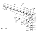
- FIG. 1 is a perspective view schematically showing an example of the appearance of the display device according to the first embodiment.
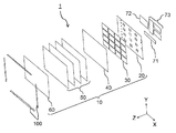
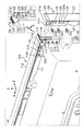
- FIG. 2 is an exploded perspective view schematically showing an example of the configuration of the display device in the first embodiment.
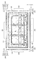
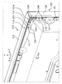
- FIG. 3 is a plan view schematically showing an example of the configuration of the back side of the display device in the first exemplary embodiment.
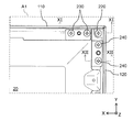
- FIG. 4 is an exploded view schematically showing an example of the configuration of the display device in the first embodiment.
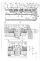
- FIG. 5 is an enlarged view showing a part of the display device in the first embodiment.
- FIG. 6 is an enlarged view showing another part of the display device in the first embodiment.
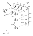
- FIG. 7 is an exploded perspective view schematically showing an example of the configuration of the connecting member disposed on the upper side of the display device in the first embodiment.
- FIG. 8 is a diagram schematically illustrating a state in which a bezel portion and a metal fitting which are arranged on the upper side of the display device in the first embodiment are connected to each other.
- FIG. 9 schematically shows a state in which the bezel portion arranged on the upper side of the display device and the bezel portion arranged on one short side of the display device are connected to each other by the connecting member in the first embodiment.
- FIG. 10 is an enlarged view schematically showing an example of the appearance of the corner of the bezel of the display device in the first embodiment.
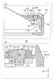
- FIG. 11 is a partial cross-sectional view of the display device in the first embodiment.
- FIG. 12 is a partial cross-sectional view of the display device in the first embodiment.
- This disclosure provides a display device that can be easily reduced in size when viewed from the front while maintaining the size of the display area.
- each drawing shows three axes, that is, an X axis, a Y axis, and a Z axis, and description will be made using the XYZ axes as necessary.
- the direction parallel (substantially parallel) to the long side of the display area 101 of the display device 1 installed on the installation surface is defined as the X-axis direction and parallel to the short side of the display area 101.
- a (substantially parallel) direction is a Y-axis direction, and a direction orthogonal to both the X-axis and the Y-axis is a Z-axis direction.
- a direction relatively far from the installation surface is up
- a direction relatively close to the installation surface is down
- a direction from the bottom to the top is a Y-axis positive direction.
- the front surface or the front surface of the display area 101 is the front surface or the front surface
- the surface opposite to the front surface is the back surface or the rear surface
- the direction from the back surface to the front surface is the positive Z-axis direction.
- the direction from left to right toward the front of the display area 101 is defined as the positive X-axis direction.
- each part will be described based on the display device 1 placed on an installation surface substantially parallel to the horizontal plane (XZ plane).
- the Y axis positive direction is up
- the Y axis negative direction is down
- the X axis and Z axis are the same as in other drawings. .
- these directions are relative for convenience and are not absolute. Further, the present disclosure is not limited by these directions.
- the display device 1 shown as an example in the first embodiment is a liquid crystal display device including a liquid crystal display panel as the display panel 60.
- FIG. 1 is a perspective view schematically showing an example of the appearance of the display device 1 in the first embodiment.
- the display device 1 has the appearance of a general flat panel display in which a display module 10 (see FIG. 2) including a display panel 60 is stored in a housing 1a.
- the display area 101 is configured to display a moving image or a still image based on the video signal.
- FIG. 2 is an exploded perspective view schematically showing an example of the configuration of the display device 1 according to the first embodiment.
- the display device 1 includes a bezel 100, a display module 10, a connection terminal board 71, a signal processing board 72, and a power supply board 73.
- the display module 10 includes a base plate 20, a plurality of light source substrates 30, a reflection sheet 40, various optical sheets 50, and a display panel 60.
- the display device 1 further includes a back cover (not shown) that covers the back side of the base plate 20.
- the display module 10, the connection terminal board 71, the signal processing board 72, and the power supply board 73 are housed in a housing 1 a (see FIG. 1) configured to include the back cover and the bezel 100. Is configured.
- the display device 1 may include a support member, a fastening member, a reinforcing member, and the like in addition to these members, and illustration of these members is omitted. Explanation regarding these members will be given as necessary.
- the base plate 20 is a support substrate used as a base on which the light source substrate 30, the connection terminal substrate 71, the signal processing substrate 72, and the power supply substrate 73 are attached.
- the base plate 20 is made of, for example, a plate-like metal.
- the base plate 20 is provided with a plurality of through holes and screw holes for attaching various members, and the light source substrates 30 are electrically connected to each other with a cable passing through the back side (Z-axis negative direction side) of the base plate 20.
- a plurality of openings used for electrically connecting the light source substrate 30 and another substrate are provided.
- the light source substrate 30 is a backlight module that is provided on the back side (Z-axis negative direction side) of the display panel 60 and irradiates the display panel 60 with light from the back side.
- the light source substrate 30 has a plurality of light sources on a main surface which is a front surface side (Z-axis positive direction side) of the light source substrate 30, and irradiates light emitted from the plurality of light sources on the rear surface side of the display panel 60. .
- the light source substrate 30 also has a driver element that drives each of the plurality of light sources.
- Each of the plurality of light sources is, for example, a point light source constituted by a light emitting diode (LED: Light Emitting Diode).
- a plurality of light source substrates 30 having the same (substantially the same) shape are attached to the front surface (the surface on the Z axis positive direction side) of the base plate 20 in a state of being arranged in a matrix.
- the plurality of light source substrates 30 constitute a direct type backlight that illuminates the display panel 60 from the back.
- the reflection sheet 40 is a sheet that reflects light and is disposed on the main surface (the surface on the Z-axis positive direction side) of the light source substrate 30.
- the reflection sheet 40 has a plurality of openings for penetrating each of the plurality of light sources provided in the light source substrate 30.
- the reflection sheet 40 reflects light traveling in the back direction (Z-axis negative direction) out of the light emitted from each light source penetrating each of the openings toward the front surface (in the Z-axis positive direction). To do.
- the reflection sheet 40 is made of, for example, a white synthetic resin.
- the plurality of optical sheets 50 are disposed between the display panel 60 and the reflection sheet 40 and have various optical functions.
- the plurality of optical sheets 50 are, for example, a diffusion plate that further improves the uniformity of light brightness by diffusing light emitted from the light source substrate 30, and a path of light emitted from the light source substrate 30 in the front direction ( A prism sheet that improves brightness visually recognized by the user by aligning in the positive direction of the Z axis).
- Each optical sheet 50 can be made of, for example, a synthetic resin formed on the surface with a fine shape corresponding to the function.
- the display panel 60 is a video display liquid crystal panel configured by arranging a plurality of pixels in a matrix.
- the display panel 60 displays an image based on an image signal input to a drive circuit (not shown).
- the bezel 100 is a support member that supports the outer periphery of the display module 10.
- the bezel 100 is made of, for example, a synthetic resin.
- the connection terminal board 71 is a circuit board provided with a terminal for receiving a video signal and an interface circuit.
- the signal processing board 72 is a circuit board provided with a signal processing circuit for processing a video signal.
- the signal processing board 72 is also provided with a circuit for generating a control signal for controlling (dimming) the luminance of the light source of the light source board 30 based on the video signal.
- the power supply board 73 is a circuit board provided with a power supply circuit for supplying operating power to the display device 1.
- the connection terminal board 71, the signal processing board 72, and the power supply board 73 are attached to the back surface of the base plate 20.
- FIG. 3 is a plan view schematically showing an example of the configuration on the back side of the display device 1 in the first embodiment.
- substrates from the back side is shown.
- FIG. 4 is an exploded view schematically showing an example of the configuration of the display device 1 according to the first embodiment.
- FIG. 4 shows a state where the bezel 100 is removed from the base plate 20.
- FIG. 5 is an enlarged view showing a part of the display device 1 according to the first embodiment.
- FIG. 5 shows an enlarged view of the portion shown as region A1 in FIG.
- FIG. 6 is an enlarged view showing another part of the display device 1 according to the first embodiment.
- FIG. 6 shows an enlarged view of the portion shown as region A2 in FIG.
- the bezel 100 includes a plurality of (for example, four) bezel portions 110 to 140, a connecting member 200, and a connecting member 250.
- Each of the plurality of bezel portions 110 to 140 is a long member arranged corresponding to each of the four sides of the display area 101.
- the bezel portion 110 and the bezel portion 130 are long members extending in the horizontal direction (X-axis direction), and the bezel portion 120 and the bezel portion 140. Is a long member extending in the vertical direction (Y-axis direction).
- the connecting member 200 and the connecting member 250 are members that connect two adjacent bezel portions of the plurality of bezel portions 110 to 140 to each other.
- the connecting member 200 and the connecting member 250 connect end portions of two adjacent bezel portions of the plurality of bezel portions 110 to 140 so as to be substantially perpendicular to each other. Thereby, the rectangular bezel 100 surrounding the outer periphery of the display module 10 is configured.
- the connecting member 200 includes a metal fitting 210 and connecting members 220 to 240.
- the one end of the bezel portion 110 (the end on the X-axis negative direction side) and the upper end portion of the bezel portion 120 (the end on the Y-axis positive direction side) are connected to each other, and the other end of the bezel portion 110 is connected.
- the end on the X-axis positive direction side) and the upper end (the end on the Y-axis positive direction side) of the bezel part 140 are connected to each other.
- the connecting member 250 includes a metal fitting 260 and a connecting member 270. At the lower corners of the display device 1 (that is, the corners on the X axis negative direction side and the Y axis negative direction side, and the corners on the X axis positive direction side and the Y axis negative direction side), the connecting member 250 The one end portion (end portion on the negative X-axis direction side) of the bezel portion 130 and the lower end portion (end portion on the negative Y-axis direction side) of the bezel portion 120 are connected to each other, and the other end portion of the bezel portion 130 is connected. (The end on the X-axis positive direction side) and the lower end (the end on the Y-axis negative direction side) of the bezel portion 140 are connected to each other.
- Side and Y-axis positive direction side corner has substantially the same structure except that it is bilaterally symmetric. Therefore, in the following, the upper right corner (the corner on the X axis negative direction side and the Y axis positive direction side) of the display device 1 as viewed from the back will be mainly described, and the upper left corner (X axis of the display device 1).
- a description of the corners on the positive direction side and the Y axis positive direction side is omitted.
- the portions other than the corners of the bezel 100 are fixed to the four sides of the base plate 20 by connecting members 281 to 284.
- the bezel 100 includes a plurality of (for example, three) connection members 281 at a plurality of locations (for example, three locations) excluding an end portion in the longitudinal direction of the bezel portion 110.
- the upper side of the base plate 20 (the long side on the Y axis positive direction side) is fixed.
- a plurality of (for example, two) portions of the portion excluding the end portion in the longitudinal direction of the bezel portion 120 are connected to a short side (one side) of the base plate 20 by a plurality of (for example, two) connecting members 282. It is fixed to the X-axis negative direction side (short side) side.
- a plurality of portions (for example, five locations) excluding the end portion in the longitudinal direction of the bezel portion 130 are arranged at the lower side (Y-axis negative) of the base plate 20 by a plurality of (for example, five) connection members 283. The long side of the direction side) is fixed.
- the bezel 100 includes a plurality of (for example, two) connecting members 284 at a plurality of portions (for example, two locations) of the bezel portion 140 excluding an end portion in the longitudinal direction. It is fixed to the X-axis positive direction side (short side) side.
- connection members 281 to 284 are, for example, metal screws.
- the bezel portions 110 to 140 are screwed into the screw holes provided in the base plate 20 with the connection members 281 to 284 passing through the through holes provided in the bezel portions 110 to 140, respectively. By doing so, it is fixed to the base plate 20.
- the bezel portion 110 disposed on the upper side (long side on the Y-axis positive direction side) side of the base plate 20 is a connection that penetrates the bezel portion 110 from the back side (in the Z-axis positive direction).
- the member 281 is fixed on the back surface side (Z-axis negative direction side) of the base plate 20.
- the bezel portion 120 disposed on one short side (the short side on the X axis negative direction side) of the base plate 20 is connected by a connecting member 282 that penetrates the bezel portion 120 from the back side (in the Z axis positive direction).
- the bezel part 140 fixed on the back side (Z-axis negative direction side) of the base plate 20 and disposed on the other short side (short side on the X-axis positive direction side) of the base plate 20 Is fixed on the back side (Z-axis negative direction side) of the base plate 20 by a connecting member 284 that passes through (in the Z-axis positive direction).
- the bezel portion 130 disposed on the lower side (long side on the Y-axis negative direction side) of the base plate 20 is connected to the base plate 20 by a connecting member 283 that penetrates the bezel portion 130 from the lower side (in the Y-axis positive direction). It is fixed on the lower surface (surface on the Y axis negative direction side) side.
- connection members 220 to 240 of the connecting member 200 are used for connecting the bezel part 110 and the bezel part 120 as shown in FIG. 5, and similarly, the bezel part 110 and the bezel part 140 are connected to each other. Used for concatenation. That is, the connection members 220 to 240 may not be used for the purpose of fixing the bezel 100 to the base plate 20. The bezel 100 only needs to be fixed to the base plate 20 by the connection members 281 to 284 at a position away from the arrangement position of the connecting member 200.
- the connecting member 200 disposed at the upper left corner (X-axis positive direction side and Y-axis positive direction side) of the display device 1 when viewed from the back side has a metal fitting 210 in the shape of the display device shown in FIG. 7 except that the shape of the metal fitting 210 of the connecting member 200 disposed at the corner on the upper right side (the negative X-axis side and the positive Y-axis side) of FIG. Since it is substantially the same structure, description is abbreviate
- the metal fitting 210 of the connecting member 200 arranged at the upper left corner of the display device 1 has substantially the same shape as the metal fitting 210 of the connecting member 200 arranged at the upper right corner of the display device 1. A thing may be used in a state rotated 90 degrees counterclockwise.
- FIG. 7 is an exploded perspective view schematically showing an example of the configuration of the connecting member 200 arranged on the upper side (the long side on the Y-axis positive direction side) of the display device 1 in the first embodiment.
- the connecting member 200 includes an L-shaped plate-shaped metal fitting 210 and connection members 220 to 240.
- the connection members 220 to 240 are, for example, metal stepped screws.
- the metal fitting 210 has two straight portions (a straight portion 211 and a straight portion 212) that form a substantially right-angle shape on the same plane (XY plane). Specifically, the metal fitting 210 has a rectangular plate-like linear portion 211 whose longitudinal direction extends along the X-axis direction and a rectangular plate-like linear portion 212 whose longitudinal direction extends along the Y-axis direction. The straight line portion 211 and the straight line portion 212 are formed on the same plane (XY plane).
- the bracket 210 is disposed on the bezel portion 110 disposed on the upper side (long side on the Y axis positive direction side) of the base plate 20 and on one short side (short side on the X axis negative direction side) of the base plate 20. This is a member for connecting the bezel part 120 to each other.
- the straight portion 211 of the metal fitting 210 corresponds to the bezel portion 110 and has a shape that overlaps one end portion in the longitudinal direction of the bezel portion 110 (end portion on the negative X-axis side) and the front-rear direction (Z-axis direction). Is formed.
- the straight portion 212 of the metal fitting 210 corresponds to the bezel portion 120 and has a shape that overlaps one end portion in the longitudinal direction of the bezel portion 120 (end portion on the Y-axis positive direction side) and the front-rear direction (Z-axis direction). Is formed.
- the metal fitting 210 has a plurality of (for example, two) fixing holes 214 to which the connecting member 230 is fixed in the straight portion 211.
- the metal fitting 210 has a plurality of (for example, two) fixing holes 217 to which the connection member 240 is fixed in the straight portion 212.
- the metal fitting 210 has a fixing hole 213 in which the connecting member 220 is fixed at a corner portion of the metal fitting 210 where the straight portion 211 and the straight portion 212 intersect.
- the fixing holes 213, 214, and 217 are formed with internal threads on the inner surfaces.
- the two fixing holes 214 are arranged on the lateral side (X-axis positive direction side) of the fixing hole 213, and are arranged in parallel in the horizontal direction (X-axis direction) in the linear portion 211.
- the two fixing holes 217 are arranged on the lower side (Y-axis negative direction side) of the fixing hole 213 and are arranged in parallel in the vertical direction (Y-axis direction) in the straight portion 212.
- the metal fitting 210 has a substantially cylindrical convex portion 215 and a convex portion 218 that are formed to protrude to the back side (Z-axis negative direction side).
- the convex portion 215 is disposed between the two fixing holes 214 in the linear portion 211.
- the convex portion 218 is disposed between the two fixing holes 217 in the linear portion 212.
- the metal fitting 210 has a plurality of (for example, two) protrusions 216 and a plurality of (for example, two) protrusions 219 that are formed to protrude to the back side (Z-axis negative direction side).
- the two protrusions 216 are disposed on the straight portion 211. Specifically, each of the two protrusions 216 is disposed at a position on the lower side (Y-axis negative direction side) of each of the two fixing holes 214.
- the arrangement positions of the two protrusions 216 are set to be arranged at positions inside the display area 101 when viewed in the front-rear direction of the display module 10 (from the Z-axis direction).
- the two protrusions 219 are disposed on the straight line portion 212. Specifically, each of the two protrusions 219 is disposed at a position on the lateral side (X-axis positive direction side) of each of the two fixing holes 217. The arrangement positions of the two protrusions 219 are set so as to be arranged at positions inside the display area 101 when viewed in the front-rear direction of the display module 10 (from the Z-axis direction).
- connection members 220 to 240 include two straight portions 211 and 212 that the metal fitting 210 has, and two adjacent bezel portions of the plurality of bezel portions 110 to 140 (for example, the bezel portion 110 and the bezel portion 120). Are mutually connected in a state where they are stacked on each other in the front-rear direction (Z-axis direction) of the display module 10.
- the connecting member 230 is screwed with the fixing hole 214 of the metal fitting 210 in a state where the linear portion 211 of the metal fitting 210 and the bezel portion 110 are overlapped with each other in the front-rear direction (Z-axis direction) of the display module 10.
- the bezel part 110 and the metal fitting 210 are connected to each other.
- the connecting member 240 is screwed into the fixing hole 217 of the metal fitting 210 in a state where the linear portion 212 of the metal fitting 210 and the bezel portion 120 are overlapped with each other in the front-rear direction (Z-axis direction) of the display module 10.
- the bezel portion 120 and the metal fitting 210 are connected to each other.
- the connection member 220 displays the corner of the metal fitting 210, the end of the bezel 110 (the end on the X axis negative direction side), and the end of the bezel 120 (the end on the Y axis positive direction side).
- the bezel part 110, the bezel part 120, and the metal fitting 210 are connected to each other by screwing into the fixing hole 213 of the metal fitting 210. In this manner, the metal fitting 210 and the connection members 220 to 240 connect the adjacent bezel portions 110 and 120 to each other.
- FIG. 8 is a diagram schematically showing a state in which the bezel portion 110 and the metal fitting 210 arranged on the upper side (the long side on the Y-axis positive direction side) of the display device 1 in Embodiment 1 are connected to each other. .
- FIG. 9 shows a bezel portion 110 arranged on the upper side (the long side on the Y-axis positive direction side) of the display device 1 according to Embodiment 1 and one short side (the short side on the X-axis negative direction side) of the display device 1. It is a figure which shows typically a mode that the bezel part 120 arrange
- FIG. 9B is a perspective view when the bezel portion 120 is viewed from the front side (Z-axis positive direction side).
- FIG. 10 is an enlarged view of a corner portion of the bezel 100 of the display device 1 in the first embodiment.
- FIG. 10 shows a corner portion of the bezel 100 after the bezel 100 is attached to the base plate 20 (the corner portion at the upper right end when the display device 1 is viewed from the back side, the X-axis negative direction side and the Y-axis positive direction). The side corners) are shown enlarged.
- the bezel portion 110 disposed on the upper side (the long side on the Y-axis positive direction side) of the base plate 20 includes a back surface portion 111, a side surface portion 112, and a front surface portion 113.
- the back surface portion 111 is a plate-like member disposed on the back surface side (Z-axis negative direction side) of the bezel portion 110.
- the side surface portion 112 is a plate-like member disposed on the upper surface (side surface on the Y axis positive direction side) side of the bezel portion 110.
- the side surface portion 112 is a portion that forms the upper side surface (upper surface) of the housing of the display device 1.
- the front surface portion 113 is a plate-like member disposed on the front surface side (Z-axis positive direction side) of the bezel portion 110.
- the front part 113 is a part that forms a frame arranged on the upper side (long side on the Y axis positive direction side) of the display area 101 (see FIG. 1) on the front side of the display device 1.
- the back surface portion 111 is formed so as to protrude downward (Y-axis negative direction side) from the end portion on the back surface side (Z-axis negative direction side) of the side surface portion 112.
- the front surface portion 113 is formed so as to protrude downward (Y-axis negative direction side) from an end portion of the side surface portion 112 on the front surface side (Z-axis positive direction side).
- the back surface portion 111, the side surface portion 112, and the front surface portion 113 are long plate-like members extending in the horizontal direction (X-axis direction).
- the bezel portion 110 has a substantially C-shape when viewed from the longitudinal direction (X-axis direction), and is one of the four sides of the base plate 20 between the front surface portion 113 and the back surface portion 111. Sides (upper side, long side on the Y axis positive direction side) can be arranged.
- the back surface portion 111 of the bezel portion 110 has a longitudinal direction (X axis) on one end side (an end side in the X axis negative direction) in the longitudinal direction (X axis direction) of the bezel portion 110.
- a plurality of through holes arranged in parallel in the direction).
- the back surface portion 111 of the bezel portion 110 has a first through hole 114 arranged at the outermost end in the longitudinal direction (end portion in the negative direction of the X axis) as the plurality of through holes, and is longer than the first through hole 114.
- Two second through holes 115 disposed on the inner side in the direction (X axis positive direction side than the first through hole 114).
- the back surface portion 111 of the bezel portion 110 further includes a third through hole 116 between the two second through holes 115. That is, the plurality of through-holes extend from one end (end on the X-axis negative direction side) in the longitudinal direction (X-axis direction) to the longitudinal direction (X-axis positive direction) on the back surface portion 111 of the bezel portion 110.
- the first through hole 114, the second through hole 115, the third through hole 116, and the second through hole 115 are arranged in parallel in this order, and penetrate the back surface portion 111 in the thickness direction (Z-axis direction). ing.
- the back surface portion 111 of the bezel portion 110 is connected to the metal fitting 210 by the connecting member 230.
- the second portion 111b in which the second through hole 115 of the bezel portion 110 is formed and the straight portion 211 of the metal fitting 210 are connected to the fixing hole 214 and the second through hole 115 of the straight portion 211.
- Z-axis direction the front-rear direction
- the bezel portion 110 and the metal fitting 210 are arranged in the front-rear direction (Z-axis) so that the second portion 111b of the bezel portion 110 is disposed on the back side (Z-axis negative direction side) of the straight portion 211 of the metal fitting 210.
- the connecting member 230 is threaded into the fixing hole 214 of the metal fitting 210 through the second through hole 115 from the back side (in the positive direction of the Z axis).
- the back surface part 111 and the metal fitting 210 of the bezel part 110 are mutually connected.
- the convex portion 215 formed on the straight portion 211 of the metal fitting 210 is fitted into the third through hole 116 from the front side (Z-axis positive direction side) of the second portion 111b.
- the second through hole 115 and the fixing hole 214 of the metal fitting 210 are in the front-rear direction (Z-axis direction).
- the convex portion 215 and the third through hole 116 are formed so as to overlap each other and the first through hole 114 and the fixing hole 213 of the metal fitting 210 overlap each other in the front-rear direction (Z-axis direction).
- the metal fitting 210 when the metal fitting 210 is connected to the bezel portion 110, the metal fitting 210 can be easily attached to a predetermined position (each through hole and each of the bezel portions 110) simply by fitting the convex portion 215 to the third through hole 116.
- the fixing holes can be arranged in positions where they overlap each other in the front-rear direction (Z-axis direction).
- the base plate 20 is disposed between the back surface portion 111 and the front surface portion 113 of the bezel portion 110.
- the bezel portion 120 is fixed to the metal fitting 210 by the connecting member 220 and the connecting member 240.
- the bezel portion 110 and the bezel portion 120 are connected to each other.
- the bezel portion 120 disposed on one short side (the short side on the X-axis negative direction side) side of the base plate 20 has a back surface portion 121, a side surface portion 122, and a bezel portion 110. And a front surface portion 123.
- the back surface portion 121 is a plate-like member disposed on the back surface side (Z-axis negative direction side) of the bezel portion 120.
- the side surface portion 122 is a plate-like member disposed on one side surface (side surface on the X axis negative direction side) of the bezel portion 120.
- the side surface portion 122 is a portion that forms one side surface of the housing of the display device 1 (a short side surface of the display device 1 on the X axis negative direction side).
- the front surface portion 123 is a plate-like member disposed on the front surface side (Z-axis positive direction side) of the bezel portion 120.
- the front part 123 is a part that forms a frame arranged on one short side (short side on the X axis negative direction side) of the display region 101 (see FIG. 1) on the front surface of the display device 1.
- the back surface portion 121 is formed so as to protrude laterally (X-axis positive direction side) from the end portion on the back surface side (Z-axis negative direction side) of the side surface portion 122.
- the front surface portion 123 is formed so as to protrude laterally (X-axis positive direction side) from the end portion on the front surface side (Z-axis positive direction side) of the side surface portion 122.
- the back surface portion 121, the side surface portion 122, and the front surface portion 123 are long plate-like members extending in the vertical direction (Y-axis direction).
- the bezel portion 120 is similar to the rear portion 111, the side portion 112, and the front portion 113 of the bezel portion 110.
- the directions are connected so as to be substantially orthogonal, and the side surface portion 122 and the front surface portion 123 are connected so that their short directions are substantially orthogonal. Therefore, the bezel portion 120 has a substantially C-shape when viewed from the longitudinal direction (Y-axis direction), and the other of the four sides of the base plate 20 between the front surface portion 123 and the back surface portion 121. 1 side (short side on the X-axis negative direction side) can be arranged.
- the bezel part 140 has substantially the same structure as the bezel part 120 except that it is symmetrical with the bezel part 120. Therefore, although detailed description is omitted, the bezel portion 140 has a substantially C-shape when viewed from the longitudinal direction (Y-axis direction), and the base plate 20 is interposed between the front surface portion and the back surface portion. Another one of the four sides (the short side on the X axis positive direction side) can be arranged. Similarly, the bezel part 130 has substantially the same structure as the bezel part 110 except that the bezel part 110 is vertically symmetrical and the connection direction of the connection member 283 is different.
- the bezel portion 130 has a substantially C-shape when viewed from the longitudinal direction (X-axis direction), and the base plate 20 is interposed between the front surface portion and the back surface portion.
- the remaining one of the four sides (lower side, long side on the Y-axis negative direction side) can be arranged.
- the back surface portion 121 of the bezel portion 120 is, like the back surface portion 111 of the bezel portion 110, one end side (Y-axis direction) in the longitudinal direction (Y-axis direction) of the bezel portion 120.
- a plurality of through holes arranged in parallel in the longitudinal direction (Y-axis direction) are provided on the end side on the axial positive direction side.
- the back surface portion 121 of the bezel portion 120 includes a first through hole 124 disposed at the outermost end in the longitudinal direction (end portion in the positive Y-axis direction) and a lower portion than the first through hole 124 as the plurality of through holes.
- Two second through-holes 125 disposed on the side (Y-axis negative direction side).
- the back surface portion 121 of the bezel portion 120 further includes a third through hole 126 between the two second through holes 125. That is, the plurality of through-holes extend from one end portion (end portion on the Y-axis positive direction side) in the longitudinal direction (Y-axis positive direction) to the longitudinal direction (Y-axis negative direction) on the back surface portion 121 of the bezel portion 120.
- the first through hole 124, the second through hole 125, the third through hole 126, and the second through hole 125 are arranged in parallel in this order, and penetrate the back surface portion 121 in the thickness direction (Z-axis direction). ing.
- the back surface portion 121 of the bezel portion 120 is connected to the metal fitting 210 by the connecting member 240.
- the second portion 121b in which the second through hole 125 of the bezel portion 120 is formed and the straight portion 212 of the metal fitting 210 are connected to the fixing hole 217 and the second through hole 125 of the straight portion 212.
- Z-axis direction the front-rear direction
- the bezel portion 120 and the metal fitting 210 are arranged in the front-rear direction (Z-axis) so that the second portion 121b of the bezel portion 120 is disposed on the back side (Z-axis negative direction side) of the straight portion 212 of the metal fitting 210.
- the connection member 240 is threaded into the fixing hole 217 of the metal fitting 210 through the second through hole 125 from the back side (in the positive Z-axis direction).
- the back surface part 121 and the metal fitting 210 of the bezel part 120 are mutually connected.
- the first portion 121a in which the first through hole 124 of the bezel portion 120 is formed overlaps the first portion 111a in which the first through hole 114 of the bezel portion 110 is formed. It overlaps with the corner part.
- the 1st through-hole 114 of the bezel part 110, the 1st through-hole 124 of the bezel part 120, and the fixing hole 213 (refer FIG. 7) of the metal fitting 210 have mutually overlapped in the front-back direction (Z-axis direction). It becomes.
- connection member 220 is passed through the first through hole 114 of the bezel part 110 and the first through hole 124 of the bezel part 120 from the back side (in the positive direction of the Z axis) to fix the fixing hole 213 of the metal fitting 210. (See FIG. 7).
- the back surface part 121 and the metal fitting 210 of the bezel part 120 are mutually connected.
- one end of the bezel portion 110 (the end on the X-axis negative direction side) and one end of the bezel portion 120 (the end on the Y-axis positive direction side) are fixed to the corner of the metal fitting 210. Is done.
- the convex portion 218 formed on the straight portion 212 of the metal fitting 210 is formed on the front surface side (Z-axis positive direction side) of the second portion 121b. ) To the third through hole 126.
- the second through hole 125 and the fixing hole 217 of the metal fitting 210 are in the front-rear direction (Z-axis direction).
- the convex portion 218 and the third through hole 126 are formed so as to overlap each other and the first through hole 124 and the fixing hole 213 of the metal fitting 210 overlap each other in the front-rear direction (Z-axis direction). Therefore, when the bezel portion 120 is connected to the metal fitting 210 connected to the bezel portion 110, the bezel portion 120 can be easily attached to the bezel portion 110 only by fitting the convex portion 218 into the third through hole 126. Can be arranged at a predetermined position (position where each through hole and each fixing hole overlap each other in the front-rear direction (Z-axis direction)).
- the bezel portion 110 has a rib 117 that is formed on the portion overlapping the bezel portion 120 so as to protrude to the back side (Z-axis negative side) and extend in the longitudinal direction (X-axis direction) of the bezel portion 110. It may be.
- the bezel portion 120 may have a groove portion 127 that is recessed on the back side (Z-axis negative direction side) and formed in a shape that can be fitted to the rib 117 at a portion facing the rib 117 of the bezel portion 110. Good.
- the bezel part 110 and the bezel part 120 formed in this way are overlapped with each other so that the rib 117 and the groove part 127 are fitted to each other, whereby the bezel part 110 and the bezel part 120 are placed in a predetermined position (each through hole). And each fixing hole can be easily overlapped in a position where they overlap each other in the front-rear direction (Z-axis direction).
- the structure shown in FIG. 10 is formed by fixing the bezel portion 110 and the bezel portion 120 and the base plate 20 in combination.
- FIG. 11 is a partial cross-sectional view of the display device 1 according to the first embodiment.
- the cross-sectional view shown in FIG. 11 is a cross-sectional view taken along the line XI-XI in FIG. 11A is a cross-sectional view taken along the line XI-XI in FIG. 5 after the bezel portion 110 and the bezel portion 120 are combined with the base plate 20, and
- FIG. 11B is a cross-sectional view of FIG.
- FIG. 11C is an enlarged view of a region A4 indicated by a broken line in FIG. 11A.
- FIG. 12 is a partial cross-sectional view of display device 1 in the first embodiment.
- the cross-sectional view shown in FIG. 12 is a cross-sectional view taken along line XII-XII in FIG. 12A is a cross-sectional view taken along the line XII-XII in FIG. 5 after the bezel portion 110 and the bezel portion 120 are combined with the base plate 20, and
- FIG. 12B is a cross-sectional view of FIG. It is an enlarged view of area
- the bezel portion 110 disposed on the upper side (the long side on the Y axis positive direction side) of the base plate 20 is a first portion in which a first through hole 114 is formed in the back surface portion 111. 111a and a second portion 111b in which a plurality of (for example, two) second through holes 115 and third through holes 116 are formed.
- the thickness t1 (see FIG. 11B) of the first portion 111a in the front-rear direction (Z-axis direction) is the thickness t2 of the second portion 111b in the front-rear direction (Z-axis direction). (See FIG. 11C).
- the bezel portion 120 disposed on one short side (the short side on the X-axis negative direction side) of the base plate 20 has a first through hole 124 formed in the back surface portion 121.
- a second portion 121b in which a plurality of (for example, two) second through holes 125 and third through holes 126 are formed.
- the thickness t3 (see FIG. 11B) of the first portion 121a in the front-rear direction (Z-axis direction) is the front-rear direction (Z-axis direction) of the second portion 121b.
- Thickness t4 see FIG. 12B).
- the back surface portion 121 of the bezel portion 120 has a thickness (Z) greater than the thickness t3 of the first portion 121a on the inner side (X-axis positive direction side) and the lower side (Y-axis negative direction side) than the first portion 121a.
- a thick portion 121c having a large size in the axial direction is formed.
- each of the connecting member 220, the connecting member 230, and the connecting member 240 is a stepped screw.
- the connection member 220 includes a male screw part 223 that is screwed into the fixing hole 213 of the metal fitting 210 at the tip, and a shaft part 222 having a diameter larger than that of the male screw part 223. And a head portion 221 having a diameter larger than that of the shaft portion 222.
- the connecting member 230 includes a male screw part 233 that is screwed into the fixing hole 214 of the metal fitting 210 at the tip, a shaft part 232 having a diameter larger than that of the male screw part 233, and a shaft part 232.
- the connection member 240 includes a male screw part 243 that is screwed into the fixing hole 217 of the metal fitting 210 at the tip, a shaft part 242 having a diameter larger than that of the male screw part 243, and a shaft part 242. And a head 241 having a large diameter.
- the shaft portion 222 passes through the first through hole 124 of the back surface portion 121 of the bezel portion 120 and the first through hole 114 of the back surface portion 111 of the bezel portion 110, and the male screw portion 223 has the metal fitting 210.
- the fixing hole 213 is fixed.
- connection member 230 the shaft portion 232 passes through the second through hole 115 of the back surface portion 111 of the bezel portion 110, and the male screw portion 233 is fixed to the fixing hole 214 of the metal fitting 210.
- connection member 240 the shaft portion 242 passes through the second through hole 125 of the back surface portion 121 of the bezel portion 120, and the male screw portion 243 is fixed to the fixing hole 217 of the metal fitting 210.
- the thickness in the axial direction (Z-axis direction) of the shaft portion 232 of the connecting member 230 that passes through the second through hole 115 of the second portion 111b of the bezel portion 110 is shown in FIG.
- the thickness is set to be less than the thickness t2 of the second portion 111b of the bezel portion 110. That is, the thickness t2 of the second portion 111b of the bezel portion 110 is equal to or greater than the length L2 of the shaft portion 232 of the connection member 230.
- the thickness in the axial direction (Z-axis direction) of the shaft portion 242 of the connecting member 240 that passes through the second through hole 125 of the second portion 121b of the bezel portion 120 is shown in FIG.
- the thickness is set to be less than the thickness t4 of the second portion 121b of the bezel portion 120. That is, the thickness t4 of the second portion 121b of the bezel portion 120 is equal to or greater than the length L3 of the shaft portion 242 of the connection member 240.
- the connecting member 220 passes the first portion 111a of the bezel portion 110, the first portion 121a of the bezel portion 120, and the metal fitting 210 through the first portion 111a.
- the shaft portion 222 passes through the hole 114 and the first through hole 124 of the first portion 121a, and the lower surface of the head 221 (the surface on the Z-axis positive direction side) and the upper surface of the metal fitting 210 (the surface on the Z-axis negative direction side) ) In the state where there is a gap in the front-rear direction (Z-axis direction) of the base plate 20.
- the connecting member 230 has the shaft portion 232 that passes through the second portion 111b and the metal fitting 210 of the bezel portion 110 and the second through hole 115 of the second portion 111b.
- connection member 230 includes the second portion 111b of the bezel portion 110 and the metal fitting 210, the lower surface of the shaft portion 232 (the surface on the Z-axis positive direction side), and the upper surface of the metal fitting 210 (the surface on the Z-axis negative direction side).
- the base plate 20 is connected with a gap in the front-rear direction (Z-axis direction).
- the connecting member 240 passes through the second portion 121b of the bezel portion 120 and the metal fitting 210, and the shaft portion 242 passes through the second through hole 125 of the second portion 121b.
- connection member 240 includes the second portion 121b of the bezel portion 120 and the metal fitting 210, the lower surface of the shaft portion 242 (the surface on the Z-axis positive direction side), and the upper surface of the metal fitting 210 (the surface on the Z-axis negative direction side).
- the base plate 20 is connected with a gap in the front-rear direction (Z-axis direction).
- the gap between the second through hole 115 and the shaft portion 232 of the connecting member 230 (the gap in the radial direction of the second through hole 115) is A gap between the first through hole 114 and the shaft part 222 of the connecting member 220 (a gap in the radial direction of the first through hole 114), and a gap between the first through hole 124 and the shaft part 222 of the connecting member 220 It is larger than (the gap in the radial direction of the first through hole 124).
- a gap between the second through hole 125 and the shaft portion 242 of the connection member 240 (gap in the radial direction of the second through hole 125). Is a gap between the first through hole 114 and the shaft part 222 of the connection member 220 (a gap in the radial direction of the first through hole 114), and between the first through hole 124 and the shaft part 222 of the connection member 220. It is larger than the gap between them (the gap in the radial direction of the first through hole 124).
- the metal fitting 210 and the connection members 220 to 240 constituting the connecting member 200 are connected to the rear surface side (Z-axis) of the base plate 20 constituting the display module 10. (Surface on the negative direction side) is disposed at a position overlapping the base plate 20 in the front-rear direction (Z-axis direction).
- the bezel part 140 has substantially the same structure as the bezel part 120 except that the bezel part is symmetrical to the bezel part 120. . Therefore, in the above description, the bezel portion 120 may be read as the bezel portion 140.
- the bezel portion 130 has substantially the same structure as the bezel portion 110 except that the bezel portion 110 is different from the bezel portion 110 in that the bezel portion is different from the number of the connecting members 283 and the connecting direction. Therefore, in the above description, the bezel portion 110 may be read as the bezel portion 130.
- the description of the connecting member 250 is omitted.
- the connecting member 270 included in the connecting member 250 substantially the same members as the connecting members 220 to 240 included in the connecting member 200 may be used.
- . 4 illustrates a configuration in which the connecting member 250 includes a metal fitting 260 having a shape different from that of the metal fitting 210 of the connecting member 200, the shapes of the metal fitting 210 and the metal fitting 260 illustrated are merely examples of the shape of the metal fitting. Absent.
- the metal fitting 260 shown in FIG. 4 has a shape in which some of the fixing holes and the convex portions are omitted from the metal fitting 210, but is used in substantially the same application as the metal fitting 210.
- the connecting member 250 connects the lower end of the bezel portion 120 (the Y-axis negative direction side end portion) and the one end portion of the bezel portion 130 (the X-axis negative direction side end portion) to each other by the metal fitting 260 and the connection member 270.
- the lower end of the bezel part 140 (the end part on the negative side in the Y axis) and the other end part (the end part on the positive side in the X axis) of the bezel part 130 are connected to each other by the metal fitting 260 and the connecting member 270.
- the member has substantially the same function as the connecting member 200.
- the thing of the substantially same shape as the metal fitting 210 may be used as the metal fitting 260.
- the display device includes a display module including a display panel that displays an image in a rectangular display area provided on the front surface, and a bezel that surrounds the outer periphery of the display module. And a plurality of long bezel portions arranged corresponding to each of the four sides of the display area, and a connecting member that connects two adjacent bezel portions of the plurality of bezel portions to each other.
- the connecting member is disposed at a position overlapping the display module on the rear surface side of the display module.
- the display device 1 is an example of a display device.
- the display area 101 is an example of a display area.
- the display panel 60 is an example of a display panel.
- the display module 10 is an example of a display module.
- the bezel 100 is an example of a bezel.
- the bezel portions 110 to 140 are an example of a plurality of bezel portions.
- Each of the connecting member 200 and the connecting member 250 is an example of a connecting member.
- the display device 1 shown in Embodiment 1 includes a display module 10 that includes a display panel 60 that displays an image in a rectangular display area 101 provided on the front surface, a bezel 100 that surrounds the outer periphery of the display module 10, Is provided.
- the bezel 100 includes a plurality of long bezel portions 110 to 140 disposed corresponding to each of the four sides of the display area 101, and two adjacent bezel portions (a plurality of bezel portions 110 to 140).
- the connecting member 200 and the connecting member 250 that connect the bezel portion 110 and the bezel portion 120 to each other are provided, and the connecting member 200 and the connecting member 250 are arranged on the rear surface side (Z-axis negative direction side) of the display module 10.
- the display module 10 is disposed at a position overlapping the display module 10 in the front-rear direction (Z-axis direction).
- the connecting member 200 and the connecting member 250 are provided on the rear side (back side) of the display module 10 opposite to the image display side (display area 101 side). It arrange
- each of the plurality of bezel portions may have a plurality of through holes arranged in the longitudinal direction at the end of the bezel portion in the longitudinal direction of the bezel portion.
- the connecting member may have a plate-shaped metal fitting and a connecting member.
- the connecting member may connect the metal fitting and two adjacent bezel portions of the plurality of bezel portions in a state where they are overlapped with each other in the front-rear direction of the display module.
- the connection member may include a first connection member that is commonly used for two adjacent bezel portions and a second connection member that is used for each of two adjacent bezel portions.
- the first connecting member includes a first part formed with a first through hole arranged at the outermost end in the longitudinal direction and a metal fitting among the plurality of through holes of the bezel portion, and the first through hole. You may connect in the state which penetrated and the clearance gap was vacant in the said front-back direction.
- the second connecting member passes through the second through hole through the second part and the metal fitting formed with the second through hole different from the first through hole among the plurality of through holes of the bezel portion, You may connect in the state where the clearance gap is not vacant in the front-back direction.
- the first through holes 114 and 124 and the second through holes 115 and 125 are examples of through holes.
- Each of the metal fittings 210 and 260 is an example of a metal fitting.
- Each of the connection members 220, 230, 240, and 270 is an example of a connection member.
- the first through holes 114 and 124 are examples of the first through holes.
- Each of the first portions 111a and 121a is an example of a first portion.
- the connection member 220 is an example of a first connection member.
- Each of the second through holes 115 and 125 is an example of a second through hole.
- Each of the second portions 111b and 121b is an example of a second portion.
- Each of the connection members 230 and 240 is an example of a second connection member.
- the bezel portion 110 has a plurality of through holes arranged in the longitudinal direction at the end of the bezel portion 110 in the longitudinal direction of the bezel portion 110.
- the bezel portion 120 (140) has a plurality of through holes arranged in the longitudinal direction at the end of the bezel portion 120 (140) in the longitudinal direction of the bezel portion 120 (140).
- the connecting member 200 includes a plate-shaped metal fitting 210 and connecting members 220 to 240.
- connection members 220 to 240 connect the metal fitting 210 and two adjacent bezel portions (for example, the bezel portion 110 and the bezel portion 120) of the plurality of bezel portions 110 to 140 to the front and rear direction (Z (Axial direction) Connect to each other in a stacked state.
- the connection member 220 which is the first connection member among the connection members 220 to 240, is commonly used for two adjacent bezel portions (for example, the bezel portion 110 and the bezel portion 120) and is adjacent to each other.
- the first through hole disposed at the outermost end in the longitudinal direction (the end portion on the Y-axis positive direction side).
- the connection member 230 and the connection member 240 which are the second connection members among the connection members 220 to 240 are used for two adjacent bezel parts (for example, the bezel part 110 and the bezel part 120).
- the connection member 230 is formed with a second through hole 115 different from the first through hole 114 among a plurality of through holes of one of the two bezel parts adjacent to each other (for example, the bezel part 110).
- the second portion 111b and the metal fitting 210 that pass through the second through hole 115 are connected in a state where there is no gap in the front-rear direction (Z-axis direction).
- the connection member 240 is formed with a second through hole 125 different from the first through hole 124 among a plurality of through holes of the other bezel part (for example, the bezel part 120) of the two bezel parts adjacent to each other.
- the second portion 121b and the metal fitting 210 are connected through the second through hole 125 with no gap in the front-rear direction (Z-axis direction).
- the bezel part 110 and the bezel part 120 adjacent to each other are the first through holes arranged at the outermost end (end part on the X axis negative direction side) of the bezel part 110.
- the first portion 111a in which 114 is formed and in the first portion 121a in which the first through hole 124 is formed at the outermost end (the end on the Y-axis positive direction side) of the bezel portion 120, 210 are connected to each other with a gap.
- the bezel portion 110 is connected to the metal fitting 210 in a state where there is no gap in the second portion 111b in which the second through hole 115 different from the first through hole 114 is formed.
- the bezel portion 120 is connected to the metal fitting 210 in a state where there is no gap in the second portion 121b in which the second through hole 125 different from the first through hole 124 is formed.
- two adjacent bezel parts for example, the bezel part 110 and the bezel part 120
- the bezel 100 that is a connection point between two adjacent bezel portions (for example, the bezel portion 110 and the bezel portion 120) is connected. Even if the corner portion is deformed, the deformation can be allowed. Therefore, in the display device 1, even if thermal expansion or thermal contraction occurs in the bezel portions 110 to 140 due to a temperature change, it is possible to suppress the bezel 100 from being damaged due to the temperature change.
- the first part of one of the two bezel parts adjacent to each other and the first part of the other bezel part are overlapped with each other by the first connecting member. It may be connected.
- the first connecting member may connect the first portion of one bezel portion, the first portion of the other bezel portion, and the metal fitting with a gap in the front-rear direction.
- the first portion 111a) and the first portion (for example, the first portion 121a) of the other bezel portion (for example, the bezel portion 120) are overlapped with each other, and are connecting members that are first connecting members.
- 220 is connected to the metal fitting 210.
- the connection member 220 that is the first connection member includes a first part (for example, the first part 111a) of one bezel part (for example, the bezel part 110) and a first part of the other bezel part (for example, the bezel part 120).
- the part (for example, the first part 121a) and the metal fitting 210 are connected in a state where there is a gap in the front-rear direction (Z-axis direction).
- the connection member 220 includes the first portions (for example, the first portion 111a and the first portion) of the two adjacent bezel portions (for example, the bezel portion 110 and the bezel portion 120). 121a) in a state where the two bezel portions (for example, the bezel portion 110 and the bezel portion 120) and the metal fitting 210 are spaced from each other. Part 110 and bezel part 120) and metal fitting 210 are connected to each other. Thereby, in the display device 1, when the corner portion of the bezel 100 is deformed due to a temperature change, the two bezel portions (for example, adjacent to each other and connected to each other) are allowed while allowing the deformation. Further, it is possible to reduce the occurrence of a shift in the connection portion between the bezel portion 110 and the bezel portion 120).
- the first connecting member and the second connecting member may be stepped screws.
- the first connection member and the second connection member may include a male screw portion that is screwed to the metal fitting at the tip, a shaft portion having a diameter larger than that of the male screw portion, and a head portion having a diameter larger than that of the shaft portion. .
- the total thickness of the first portions of the two adjacent bezel portions may be less than the length of the shaft portion of the first connecting member in the axial direction.
- the thickness of the second portion in each of the two bezel portions adjacent to each other may be equal to or greater than the length of the shaft portion of the second connection member in the axial direction.
- each of the shaft portions 222, 232, and 242 is an example of a shaft portion.
- Each of the heads 221, 231, and 241 is an example of a head.
- Each of the first portion 111a thickness t1 and the first portion 121a thickness t3 is an example of the thickness of the first portion.
- the length L1 of the shaft portion of the connection member 220 is an example of the length of the shaft portion of the first connection member.
- Each of the thickness t2 of the second part 111b and the thickness t4 of the second part 121b is an example of the thickness of the second part.
- Each of the length L2 of the shaft portion 232 of the connecting member 230 and the length L3 of the shaft portion 242 of the connecting member 240 is an example of the length of the shaft portion of the second connecting member.
- connection member 220 that is the first connection member and the connection members 230 and 240 that are the second connection members are stepped screws.
- the connecting member 220 as the first connecting member includes a male screw part 223 screwed into the metal fitting 210 at the tip, a shaft part 222 having a diameter larger than that of the male screw part 223, a head part 221 having a diameter larger than that of the shaft part 222, Have
- the connection member 230 that is the second connection member includes a male screw part 233 that is screwed to the metal fitting 210 at the tip, a shaft part 232 having a diameter larger than that of the male screw part 233, a head part 231 having a diameter larger than that of the shaft part 232, Have
- the connection member 240 as the second connection member includes a male screw part 243 that is screwed to the metal fitting 210 at the tip, a shaft part 242 having a diameter larger than that of the male screw part 243, and a head part
- the total thickness (t1 + t3) of the first portion 121a is less than the length L1 in the axial direction of the shaft portion 222 of the connecting member 220, which is the first connecting member.
- the thickness t2 of the second portion 111b in one bezel portion (for example, the bezel portion 110) of two bezel portions adjacent to each other (for example, the bezel portion 110 and the bezel portion 120) is that of the connection member 230 that is the second connection member.
- the thickness t4 of the second portion 121b in the other bezel portion is not less than the length L2 in the axial direction of the shaft portion 232, and the thickness t4 of the second portion 121b of the connecting member 240 that is the second connecting member. It is the length L3 or more in the axial direction.
- the connection member 220 that is a stepped screw has one bezel portion (for example, the bezel portion 110) of two adjacent bezel portions (for example, the bezel portion 110 and the bezel portion 120). ) And the first portion 121a of the other bezel portion (for example, the bezel portion 120), the first portion 111a and the first portion 121a are spaced apart in the front-rear direction (Z-axis direction). And the metal fitting 210 can be easily connected to each other. Further, the connection members 230 and 240 that are stepped screws are provided in the second portion 111b of one bezel portion (for example, the bezel portion 110) of two adjacent bezel portions (for example, the bezel portion 110 and the bezel portion 120).
- the second portion 111b and the metal fitting 210 are applied with a predetermined pressing force (for example, a pressing force generated by a difference between the length L2 and the thickness t2 and a tightening force of the connecting member 230 as the second connecting member).
- a predetermined pressing force for example, a pressing force generated by a difference between the length L2 and the thickness t2 and a tightening force of the connecting member 230 as the second connecting member.
- a predetermined pressing force for example, the difference between the length L3 and the thickness t4, and the connection member 240 which is the second connection member.
- the gap in the radial direction of the second through hole between the second through hole and the second connecting member is larger than the gap in the radial direction of the first through hole between the first through hole and the first connecting member. May be larger.
- the gap in the radial direction of the second through hole 115 between the second through hole 115 and the connection member 230 that is the second connection member is the same as the first through hole 114. It is larger than the gap in the radial direction of the first through hole 114 with the connection member 220 as the first connection member, and is larger than the gap in the radial direction of the first through hole 124 between the first through hole 124 and the connection member 220. large. Further, the gap in the radial direction of the second through hole 125 between the second through hole 125 and the connection member 240 as the second connection member is between the first through hole 114 and the connection member 220 as the first connection member. It is larger than the gap in the radial direction of the first through hole 114 and larger than the gap in the radial direction of the first through hole 124 between the first through hole 124 and the connecting member 220.
- the second portion 111b is allowed to move in the radial direction of the second through hole 115 (movement on the XY plane), and the second portion 121b is It is allowed to move in the radial direction of the two through-holes 125 (movement on the XY plane).
- the first portion 111a is allowed to move in the circumferential direction of the first through-hole 114 (movement in the Z-axis direction), and the first portion 121a moves in the circumferential direction of the first through-hole 124 (Z-axis).
- Direction movement is allowed.
- the display device 1 allows the corner portion of the bezel 100 to be deformed due to the temperature change.
- the metal fitting is disposed at a position inside the display area from a plurality of fixing holes to which the connection member is fixed and a position of the fixing hole to which the second connection member among the plurality of fixing holes is fixed, And a protruding portion that protrudes toward the bezel portion.
- the fixing holes 213, 214, and 217 are examples of a plurality of fixing holes.
- Each of the fixing holes 214 and 217 is an example of a fixing hole to which the second connection member is fixed.
- Each of the protrusions 216 and 219 is an example of a protrusion.
- the metal fitting 210 includes a fixing hole 213 to which the connection member 220 is fixed, a fixing hole 214 to which the connection member 230 is fixed, and a fixing to which the connection member 240 is fixed. Hole 217.
- the connection member 230 that is the second connection member is fixed to the fixing hole 214
- the connection member 240 that is the second connection member is fixed to the fixing hole 217.
- the metal fitting 210 is disposed at a position inside the display area 101 (for example, a position on the Y axis negative direction side) from the position of the fixing hole 214, and protrudes toward the bezel portion (for example, the bezel portion 110) (Z axis).
- the protrusion 216 that protrudes in the negative direction and the position of the fixing hole 217 are disposed at a position inside the display area 101 (for example, a position on the negative side of the X-axis), and on the side of the bezel (for example, the bezel 120). And a projecting portion 219 that projects (projects in the negative Z-axis direction).
- the pressing force F1 (the end on the Y axis negative direction side of the bezel 110 is pressed in the Z axis negative direction) from the protrusion 216 toward the end of the bezel 110.
- the bezel portion 110 and the metal fitting 210 can be connected in a state where a force is applied, and the pressing force F1 (the end of the bezel portion 120 on the X axis positive direction side) from the protruding portion 219 toward the end portion of the bezel portion 120 can be connected.
- the bezel portion 120 and the metal fitting 210 can be connected in a state where a force pressing the portion in the negative Z-axis direction (see FIG. 12) is applied.
- the bezel portion (for example, the bezel portions 110 and 120) can be fixed to the metal fitting 210 in a state where the pressing force F ⁇ b> 1 in the twisting direction is applied to the bezel portion (for example, the bezel portions 110 and 120). it can. Therefore, in the display device 1, the bezel portion (for example, the bezel portions 110 and 120) can be prevented from being bent, and the strength of the bezel portion (for example, the bezel portions 110 and 120) can be improved. Note that it is desirable that the sizes of the protrusions 216 and 219 be appropriately set in consideration of the specifications of the bezel 100 including the strength required for the bezel 100 and the like.
- one of the two bezel portions adjacent to each other has a rib that protrudes rearward and extends in the longitudinal direction of the one bezel portion in a portion overlapping the other bezel portion. You may have.
- the other bezel portion may have a groove portion that is recessed to the rear side and that has a shape in which the rib fits in a portion facing the rib of the one bezel portion.
- the rib 117 is an example of a rib.
- the groove part 127 is an example of a groove part.
- one of the two bezel portions (for example, the bezel portion 110 and the bezel portion 120) adjacent to each other is the other bezel portion (for example, the bezel portion 110).
- a rib 117 protrudes rearward (Z-axis negative direction side) and extends in the longitudinal direction of the one bezel portion (for example, the bezel portion 110).
- the other bezel part (for example, the bezel part 120) is depressed on the rear side (Z-axis negative direction side) in a portion facing the rib 117 of the one bezel part (for example, the bezel part 110), And it has the groove part 127 of the shape where the rib 117 fits.
- two adjacent bezel parts (for example, the bezel part 110 and the bezel part 120) are placed in a predetermined position (each through hole and each fixing hole in the front-rear direction (Z-axis direction)). ) Can be easily stacked on each other.
- the display device may further include a support substrate that is disposed on the rear side of the display panel and supports the display panel.
- the bezel may be fixed to the support substrate at a position away from the position where the connecting member is disposed.
- the base plate 20 is an example of a support substrate.
- the display device 1 shown in the first embodiment further includes a base plate 20 that is disposed on the rear side of the display panel 60 and serves as a support substrate for supporting the display panel 60.
- the bezel 100 is fixed to the base plate 20 by connecting members 281 to 284 at a position away from the position where the connecting member 200 and the connecting member 250 are arranged.
- the bezel 100 is not fixed to the base plate 20 at a position where the connecting member 200 and the connecting member 250 are disposed. Therefore, the bezel portions 110 to 140 undergo thermal expansion or contraction due to temperature changes. Even if the corner portion of the bezel 100 that is generated and the connecting portion between two adjacent bezel portions (for example, the bezel portion 110 and the bezel portion 120) is deformed, the deformation can be allowed. Therefore, in the display device 1, even if thermal expansion or thermal contraction occurs in the bezel portions 110 to 140 due to a temperature change, it is possible to suppress the bezel 100 from being damaged due to the temperature change.
- the bezel part 110 and the bezel part 120 have been described as examples of two adjacent bezel parts among the plurality of bezel parts 110 to 140, but the other two bezel parts adjacent to each other.
- the bezel portion 120 and the bezel portion 130, the bezel portion 130 and the bezel portion 140, the bezel portion 110 and the bezel portion 140 are substantially the same as the configurations described in the embodiment, so that Similar effects can be obtained.
- the first embodiment has been described as an example of the technique disclosed in the present application.
- the technology in the present disclosure is not limited to this, and can be applied to embodiments in which changes, replacements, additions, omissions, and the like are made.
- the display device 1 is a liquid crystal display device including a liquid crystal display panel as the display panel 60 .
- the display device 1 is not limited to a liquid crystal display device, and may be a display device including an organic EL (Electro Luminescence) panel or other display panel.
- the display device 1 may be a television receiver, a monitor device, a computer display device, or the like.
- the configuration example in which the base plate 20 is formed of a plate-like metal has been described.
- the material for forming the base plate 20 is not limited to metal, and may be formed of other materials as long as the material has sufficient strength and durability.
- the light source substrate 30 includes the light emitting diode as the light source
- the light source may be configured by a light emitting element other than the light emitting diode (for example, an EL element).
- the light source may not be a point light source.
- the configuration example in which the plurality of light source substrates 30 is arranged on the front surface (the surface on the Z-axis positive direction side) of the base plate 20 has been described, but the display device 1 is replaced with the plurality of light source substrates 30.
- One light source substrate may be provided.
- the configuration example in which the reflection sheet 40 is formed of a white synthetic resin has been described, but the material forming the reflection sheet 40 is not limited to the synthetic resin.
- the reflection sheet 40 should just be formed with the material which can fully reflect the light radiate
- the material forming the bezel 100 is not limited to the synthetic resin.
- the bezel 100 only needs to be formed of a material having sufficient strength and durability to support the display module 10, and may be formed of, for example, a metal or other material.
- the connecting member 250 arranged at the lower part (end part on the Y-axis negative direction side) of the display device 1 is connected to the upper part (end part on the Y-axis positive direction side) of the display apparatus 1.
- the connection member 250 may be formed in the substantially same shape as the connection member 200.
- the number of the bezel portions included in the bezel 100 is not limited to four.
- the bezel 100 may include a number of bezel portions other than four.
- connection members 281 to 284 are formed of metal
- the material forming the connection members 281 to 284 is not limited to metal.
- the connection members 281 to 284 may be formed of any material as long as the material has strength and durability necessary for fixing the bezel 100 to the base plate 20.
- the number of connection members 281 to 284 and the number of locations where the bezel portions 110 to 140 are fixed to the base plate 20 described in the embodiment are merely examples. These numbers may be appropriately set according to the size of the display device 1 and the connection strength required for the bezel portions 110 to 140.
- connection members 220, 230, 240, and 270 are formed of metal.
- the material that forms the connection members 220, 230, 240, and 270 is not limited to metal. What is the connection members 220, 230, 240, and 270 as long as the materials have the strength and durability necessary to connect the adjacent bezel portions (for example, the bezel portion 110 and the bezel portion 120) to each other? It may be formed of any material.
- connection members 220, 230, 240, and 270 described in the embodiment the number of through holes through which the connection members 220, 230, 240, and 270 pass, and the connection members 220, 230, 240, and 270
- the number of fixing holes to be fixed is merely an example. These numbers may be set appropriately according to the connection strength required to connect two adjacent bezel portions.
- the optimum numerical values of the lengths L1 to L3 and the thicknesses t1 to t4 shown in the embodiment vary depending on the material forming the bezel 100, the specifications of the bezel 100, and the like. Therefore, it is desirable to appropriately set these values in consideration of the material forming the bezel 100, the specifications of the bezel 100 including the strength required for the bezel 100, and the like.
- the present disclosure is applicable to a display device that can easily reduce the size of the display device while maintaining the size of the display area.
- the present disclosure is applicable to a television receiver, a video recording / playback device, a monitor device, a computer display device, and the like.
Abstract
表示領域のサイズを維持したまま、表示装置のサイズを小型化することが容易にできる表示装置を提供する。表示装置は、前面に設けられた矩形の表示領域に映像を表示する表示パネルを含む表示モジュールと、表示モジュールの外周を囲うベゼル(100)と、を備え、ベゼル(100)は、表示領域の4辺のそれぞれに対応して配置される長尺状の複数のベゼル部(110,120,130,140)と、複数のベゼル部(110,120,130,140)のうちの互いに隣接する2つのベゼル部(110,120等)を互いに連結する連結部材(200)と、を有する。連結部材(200)は、表示モジュールの後面側において、表示モジュールと重なる位置に配置されている。
Description
本開示は、表示モジュールの周囲を囲うベゼルを有する表示装置に関する。
特許文献1は、表示装置の表示モジュールの周縁部を覆う枠体(以下、「ベゼル」ともいう)を開示する。このベゼルは、4つの枠部材を備え、4つの枠部材のうちの互いに隣接する枠部材の端部同士が連結されている構成を有する。
本開示は、表示領域の大きさを維持したまま、表示装置を小型化することが容易にできる表示装置を提供する。
本開示における表示装置は、前面に設けられた矩形の表示領域に映像を表示する表示パネルを含む表示モジュールと、前記表示モジュールの外周を囲うベゼルと、を備え、前記ベゼルは、前記表示領域の4辺のそれぞれに対応して配置される長尺状の複数のベゼル部と、前記複数のベゼル部のうちの互いに隣接する2つのベゼル部を互いに連結する連結部材と、を有し、前記連結部材は、前記表示モジュールの後面側において、前記表示モジュールと重なる位置に配置されている。
本開示における表示装置は、表示領域の大きさを維持したまま、表示装置を小型化することが容易にできる。
(本開示の基礎となった知見)
本願発明者は、特許文献1に開示されている表示装置に関し、以下の問題が生じることを見出した。
本願発明者は、特許文献1に開示されている表示装置に関し、以下の問題が生じることを見出した。
特許文献1に開示された技術を用いた表示装置では、表示面側から表示装置を見たとき(以下、「正面視」ともいう)に、表示モジュールの側方の位置において4つの枠部材のうちの互いに隣接する枠部材の端部同士が連結されている。このため、表示装置を正面視したときのベゼルの幅を十分に小さくできず、正面視における表示装置の大きさに対する表示領域の大きさの割合を十分に大きくできない、という問題が生じる。言い換えると、特許文献1に開示された技術では、表示領域の大きさを維持したまま、表示装置の正面視の大きさを小型化することが困難である。しかし、表示装置に対しては、表示領域の大きさを維持したまま、表示装置をより小型化することが望まれている。
本開示は、表示領域の大きさを維持したまま、表示装置の正面視における小型化が容易にできる表示装置を提供する。
以下、適宜図面を参照しながら、実施の形態を詳細に説明する。ただし、必要以上に詳細な説明は省略する場合がある。例えば、すでによく知られた事項の詳細説明、および実質的に同一の構成に対する重複説明等を省略する場合がある。これは、以下の説明が不必要に冗長になるのを避け、当業者の理解を容易にするためである。
なお、添付図面および以下で説明する実施の形態は、当業者が本開示を十分に理解するために提供されるのであって、いずれも本開示の一例を示すものである。以下の実施の形態で示される数値、形状、材料、構成要素、構成要素の配置位置および接続形態、等は、一例であり、これらにより特許請求の範囲に記載の主題を限定することは意図されていない。また、以下の実施の形態における構成要素のうち、最上位概念を示す独立請求項に記載されていない構成要素は、独立請求項に示された構成要素に任意に付加可能な構成要素である。
また、各図は、必ずしも厳密に図示されたものではなく、本開示をわかりやすく示すために適宜省略等を行った模式図である。また、各図において、実質的に同じ構成要素については同じ符号を付し、説明を省略または簡略化する場合がある。
なお、以下の実施の形態では、各図面にX軸、Y軸、Z軸の3軸を示し、必要に応じて、XYZ軸を用いて説明を行う。本実施の形態では、便宜的に、設置面に設置された表示装置1の表示領域101の長辺に平行(実質的に平行)な方向をX軸方向とし、表示領域101の短辺に平行(実質的に平行)な方向をY軸方向とし、X軸およびY軸の双方に直交する方向をZ軸方向とする。また、表示装置1において設置面から相対的に遠い方を上、設置面に相対的に近い方を下とし、下から上に向かう方向をY軸正方向とする。また、表示領域101の表面(画像を表示する面)を前面または正面とし、前面の反対側の面を背面または後面とし、背面から前面に向かう方向(画像を表示する方向)をZ軸正方向とし、表示領域101の前面に向かって左から右に向かう方向をX軸正方向とする。また、以下の実施の形態では、水平面(X-Z平面)に実質的に平行な設置面に載置された表示装置1に基づいて、各部の説明を行う。例えば、設置面に設置ができない分解された状態の表示装置1の説明においても、Y軸正方向を上とし、Y軸負方向を下とし、X軸Z軸についても他の図面と同様とする。しかし、これらの方向は便宜的に示す相対的なものであり、絶対的なものではない。また、これらの方向により本開示が限定されるものでもない。
(実施の形態1)
実施の形態1に一例として示す表示装置1は、表示パネル60として液晶表示パネルを備える液晶表示装置である。
実施の形態1に一例として示す表示装置1は、表示パネル60として液晶表示パネルを備える液晶表示装置である。
[1-1.構成]
図1は、実施の形態1における表示装置1の外観の一例を模式的に示す斜視図である。
図1は、実施の形態1における表示装置1の外観の一例を模式的に示す斜視図である。
図1に示すように、表示装置1は、表示パネル60を含む表示モジュール10(図2参照)が筐体1a内に格納されて構成された、一般的なフラットパネルディスプレイの外観を有する。そして、表示領域101に、映像信号に基づく動画像または静止画像を表示するように構成されている。
図2は、実施の形態1における表示装置1の構成の一例を模式的に示す分解斜視図である。
図2に示すように、表示装置1は、ベゼル100、表示モジュール10、接続端子基板71、信号処理基板72、および電源基板73を、備える。表示モジュール10は、ベースプレート20、複数の光源基板30、反射シート40、各種の光学シート50、および表示パネル60、を備えて構成される。表示装置1は、さらに、ベースプレート20の背面側を覆う背面カバー(図示せず)を備える。そして、背面カバーおよびベゼル100を含んで構成される筐体1a(図1参照)内に、表示モジュール10、接続端子基板71、信号処理基板72、および電源基板73が格納されて、表示装置1が構成されている。なお、表示装置1は、これらの部材の他に、支持部材、締結部材、および補強部材、等を有していてもよく、それらの部材の図示は省略している。それらの部材に関する説明は、必要に応じて行う。
ベースプレート20は、光源基板30、接続端子基板71、信号処理基板72、および電源基板73を取り付ける基台として用いられる支持基板である。ベースプレート20は、例えば、板状の金属で形成されている。
ベースプレート20には、各種部材を取り付けるための貫通孔およびねじ穴が複数設けられ、さらに、光源基板30同士をベースプレート20の背面側(Z軸負方向側)を通るケーブルで電気的に接続したり、光源基板30と他の基板とを電気的に接続したりするために用いられる複数の開口、等が設けられている。
光源基板30は、表示パネル60の背面側(Z軸負方向側)に設けられ、表示パネル60に背面側から光を照射するバックライトモジュールである。光源基板30は、光源基板30の前面側(Z軸正方向側)の面である主面に複数の光源を有し、表示パネル60の背面側に、それら複数の光源が発する光を照射する。光源基板30は、複数の光源の各々を駆動するドライバ素子も有する。複数の光源の各々は、例えば、発光ダイオード(LED:Light Emitting Diode)で構成された点光源である。
ベースプレート20の前面(Z軸正方向側の面)には、互いに同じ(実質的に同じ)形状の複数の光源基板30が、マトリクス状に配置された状態で取り付けられている。これら複数の光源基板30により、表示パネル60を背面から照明する直下型のバックライトが構成される。
反射シート40は、光源基板30の主面(Z軸正方向側の面)上に配置された、光を反射するシートである。反射シート40は、光源基板30が備える複数の光源の各々を貫通させるための複数の開口を有する。そして、反射シート40は、それらの開口の各々を貫通した各光源から出射された光のうち、背面方向(Z軸負方向)に進行する光を前面に向けて(Z軸正方向に)反射する。反射シート40は、例えば、白色の合成樹脂で形成されている。
複数の光学シート50は、表示パネル60と反射シート40との間に配置され、各種の光学機能を有するシートである。複数の光学シート50は、例えば、光源基板30から発せられた光を拡散することにより光の輝度の均一性をさらに向上する拡散板や、光源基板30から発せられた光の進路を前面方向(Z軸正方向)に揃えることによりユーザによって視認される輝度を向上するプリズムシート、等を含む。各光学シート50は、例えば、表面に、機能に応じた微細形状が設けられて成形された合成樹脂で構成することができる。
表示パネル60は、複数の画素がマトリクス状に配列されて構成された映像表示用の液晶パネルである。表示パネル60は、駆動回路(図示せず)に入力される映像信号に基づいた映像を表示する。
ベゼル100は、表示モジュール10の外周を支持する支持部材である。ベゼル100は、例えば、合成樹脂で形成されている。
接続端子基板71は、映像信号を受信するための端子およびインターフェース回路が設けられた回路基板である。信号処理基板72は、映像信号を処理するための信号処理回路が設けられた回路基板である。信号処理基板72には、光源基板30の光源の輝度を制御(調光)するための制御信号を、映像信号に基づいて生成する回路等も設けられている。電源基板73は、表示装置1に動作電力を供給するための電源回路が設けられた回路基板である。接続端子基板71、信号処理基板72、および電源基板73は、ベースプレート20の背面に取り付けられている。
次に、ベゼル100の詳細について説明する。
図3は、実施の形態1における表示装置1の背面側の構成の一例を模式的に示す平面図である。図3には、背面カバーおよび各種基板を除いた表示装置1を背面側から見た図を示す。
図4は、実施の形態1における表示装置1の構成の一例を模式的に示す分解図である。図4には、ベースプレート20からベゼル100を取り外した状態を示す。
図5は、実施の形態1における表示装置1の一部を拡大して示す拡大図である。図5には、図3に領域A1として示す部分を拡大して示す。
図6は、実施の形態1における表示装置1の他の一部を拡大して示す拡大図である。図6には、図3に領域A2として示す部分を拡大して示す。
なお、以下では、説明を簡略化するために、複数の光源基板30、反射シート40、各種の光学シート50、表示パネル60、背面カバー、および各基板71~73を除いた構成を説明する。
図3~図6に示すように、ベゼル100は、複数(例えば、4つ)のベゼル部110~140と、連結部材200および連結部材250と、を有する。
複数のベゼル部110~140のそれぞれは、表示領域101の4辺のそれぞれに対応して配置される長尺状の部材である。具体的には、設置面に設置された表示装置1において、ベゼル部110およびベゼル部130は、水平方向(X軸方向)に延伸した長尺状の部材であり、ベゼル部120およびベゼル部140は、鉛直方向(Y軸方向)に延伸した長尺状の部材である。
連結部材200および連結部材250は、複数のベゼル部110~140のうちの互いに隣接する2つのベゼル部同士を互いに連結する部材である。連結部材200および連結部材250は、複数のベゼル部110~140のうちの互いに隣接する2つのベゼル部の端部同士を略直角となるように連結する。これにより、表示モジュール10の外周を囲う矩形のベゼル100が構成される。
連結部材200は、金具210と、接続部材220~240とを備えて構成される。そして、表示装置1の上部の両角部(すなわち、X軸負方向側かつY軸正方向側の角部、およびX軸正方向側かつY軸正方向側の角部)では、連結部材200によって、ベゼル部110の一方の端部(X軸負方向側の端部)とベゼル部120の上端部(Y軸正方向側の端部)とが互いに連結され、ベゼル部110の他方の端部(X軸正方向側の端部)とベゼル部140の上端部(Y軸正方向側の端部)とが互いに連結されている。
連結部材250は、金具260と、接続部材270とを備えて構成される。そして、表示装置1の下部の両角部(すなわち、X軸負方向側かつY軸負方向側の角部、およびX軸正方向側かつY軸負方向側の角部)では、連結部材250によって、ベゼル部130の一方の端部(X軸負方向側の端部)とベゼル部120の下端部(Y軸負方向側の端部)とが互いに連結され、ベゼル部130の他方の端部(X軸正方向側の端部)とベゼル部140の下端部(Y軸負方向側の端部)とが互いに連結されている。
なお、背面から見た(Z軸負方向側から見た)表示装置1の右上の角部(X軸負方向側かつY軸正方向側の角部)と左上の角部(X軸正方向側かつY軸正方向側の角部)とは、左右対称であることを除いて実質的に同じ構造を有する。したがって、以下では、背面から見た表示装置1の右上の角部(X軸負方向側かつY軸正方向側の角部)について主に説明し、表示装置1の左上の角部(X軸正方向側かつY軸正方向側の角部)についての説明は省略する。
なお、図4に示すように、ベゼル100は、ベゼル100の角部以外の部分が、接続部材281~284によって、ベースプレート20の4辺に固定されている。具体的には、図4に示すように、ベゼル100は、ベゼル部110の長手方向における端部を除く部分の複数個所(例えば、3箇所)が、複数(例えば、3つ)の接続部材281によって、ベースプレート20の上辺(Y軸正方向側の長辺)側に固定されている。また、ベゼル100は、ベゼル部120の長手方向における端部を除く部分の複数個所(例えば、2箇所)が、複数(例えば、2つ)の接続部材282によって、ベースプレート20の一方の短辺(X軸負方向側の短辺)側に固定されている。また、ベゼル100は、ベゼル部130の長手方向における端部を除く部分の複数個所(例えば、5箇所)が、複数(例えば、5つ)の接続部材283によって、ベースプレート20の下辺(Y軸負方向側の長辺)側に固定されている。そして、ベゼル100は、ベゼル部140の長手方向における端部を除く部分の複数個所(例えば、2箇所)が、複数(例えば、2つ)の接続部材284によって、ベースプレート20の他方の短辺(X軸正方向側の短辺)側に固定されている。
接続部材281~284は、例えば、金属製のビスである。そして、ベゼル部110~140は、接続部材281~284の各々が、ベゼル部110~140に設けられた貫通孔の各々を貫通した状態で、ベースプレート20に設けられたねじ穴の各々に螺合することにより、ベースプレート20に固定される。また、ベースプレート20の上辺(Y軸正方向側の長辺)側に配置されるベゼル部110は、図6に示すように、ベゼル部110を背面側から(Z軸正方向に)貫通する接続部材281によって、ベースプレート20の背面側(Z軸負方向側)において固定される。同様に、ベースプレート20の一方の短辺(X軸負方向側の短辺)側に配置されるベゼル部120は、ベゼル部120を背面側から(Z軸正方向に)貫通する接続部材282によって、ベースプレート20の背面側(Z軸負方向側)において固定され、ベースプレート20の他方の短辺(X軸正方向側の短辺)側に配置されるベゼル部140は、ベゼル部140を背面側から(Z軸正方向に)貫通する接続部材284によって、ベースプレート20の背面側(Z軸負方向側)において固定される。一方、ベースプレート20の下辺(Y軸負方向側の長辺)側に配置されるベゼル部130は、ベゼル部130を下側から(Y軸正方向に)貫通する接続部材283によって、ベースプレート20の下面(Y軸負方向側の面)側において固定される。
なお、本実施の形態では、連結部材200の接続部材220~240は、図5に示すようにベゼル部110とベゼル部120との連結に使用され、同様に、ベゼル部110とベゼル部140との連結に使用される。すなわち、接続部材220~240は、ベゼル100をベースプレート20に固定する目的で使用されなくてもよい。ベゼル100は、連結部材200の配置位置から離れた位置で、接続部材281~284によって、ベースプレート20に固定されていればよい。
次に、背面側から見て表示装置1の右上側(X軸負方向側かつY軸正方向側)の角部に配置される連結部材200の具体的な構成について、図7を用いて説明する。なお、背面側から見て表示装置1の左上側(X軸正方向側かつY軸正方向側)の角部に配置される連結部材200は、金具210の形状が、図7に示す表示装置1の右上側(X軸負方向側かつY軸正方向側)の角部に配置される連結部材200の金具210の形状と左右対称であることを除いて、図7に示す連結部材200と実質的に同じ構成であるので、説明を省略する。なお、表示装置1の左上側の角部に配置される連結部材200の金具210として、表示装置1の右上側の角部に配置される連結部材200の金具210と実質的に同一の形状のものを、反時計回りに90度回転した状態で用いてもよい。
図7は、実施の形態1における表示装置1の上辺(Y軸正方向側の長辺)側に配置される連結部材200の構成の一例を模式的に示す分解斜視図である。
連結部材200は、L字形板状の金具210と、接続部材220~240と、を有する。接続部材220~240は、例えば、金属製の段付きビスである。
金具210は、同一面(X-Y平面)上において略直角の形状を構成する2つの直線部分(直線部分211、および直線部分212)を有する。具体的には、金具210は、長手方向がX軸方向に沿って延伸した矩形板状の直線部分211と、長手方向がY軸方向に沿って延伸した矩形板状の直線部分212とを有し、直線部分211と直線部分212とは、同一面(X-Y平面)上に形成されている。
金具210は、ベースプレート20の上辺(Y軸正方向側の長辺)側に配置されるベゼル部110と、ベースプレート20の一方の短辺(X軸負方向側の短辺)側に配置されるベゼル部120とを相互に連結するための部材である。金具210の直線部分211は、ベゼル部110に対応しており、ベゼル部110の長手方向の一方の端部(X軸負方向側の端部)と前後方向(Z軸方向)に重なる形状に形成されている。金具210の直線部分212は、ベゼル部120に対応しており、ベゼル部120の長手方向の一方の端部(Y軸正方向側の端部)と前後方向(Z軸方向)に重なる形状に形成されている。
金具210は、直線部分211に、接続部材230が固定される複数(例えば、2つ)の固定孔214を有する。また、金具210は、直線部分212に、接続部材240が固定される複数(例えば、2つ)の固定孔217を有する。また、金具210は、直線部分211と直線部分212とが交わる、金具210の角部に、接続部材220が固定される固定孔213を有する。固定孔213、214、217には、内面に雌ねじが形成されている。
2つの固定孔214は、固定孔213の横側(X軸正方向側)に配置され、かつ、直線部分211において水平方向(X軸方向)に並列して配置されている。2つの固定孔217は、固定孔213の下側(Y軸負方向側)に配置され、かつ、直線部分212において鉛直方向(Y軸方向)に並列して配置されている。
また、金具210は、背面側(Z軸負方向側)に突出して形成された、略円柱形状の凸部215および凸部218を有する。凸部215は、直線部分211における、2つの固定孔214の間に配置されている。凸部218は、直線部分212における、2つの固定孔217の間に配置されている。
また、金具210は、背面側(Z軸負方向側)に突出して形成された複数(例えば、2つ)の突起部216および複数(例えば、2つ)の突起部219を有する。2つの突起部216は、直線部分211に配置されている。具体的には、2つの突起部216の各々は、2つの固定孔214の各々の下側(Y軸負方向側)の位置に配置されている。2つの突起部216の配置位置は、表示モジュール10の前後方向に(Z軸方向から)見たときに、表示領域101の内側の位置に配置されるように設定されている。一方、2つの突起部219は、直線部分212に配置されている。具体的には、2つの突起部219の各々は、2つの固定孔217の各々の横側(X軸正方向側)の位置に配置されている。2つの突起部219の配置位置は、表示モジュール10の前後方向に(Z軸方向から)見たときに、表示領域101の内側の位置に配置されるように設定されている。
接続部材220~240は、金具210が有する2つの直線部分211および直線部分212と、複数のベゼル部110~140のうちの互いに隣接する2つのベゼル部(例えば、ベゼル部110およびベゼル部120)とを、表示モジュール10の前後方向(Z軸方向)に互いに重ねた状態で、相互に接続する部材である。具体的には、接続部材230は、金具210の直線部分211と、ベゼル部110とを、表示モジュール10の前後方向(Z軸方向)に互いに重ねた状態で、金具210の固定孔214と螺合することにより、ベゼル部110と金具210とを相互に接続する。接続部材240は、金具210の直線部分212と、ベゼル部120とを、表示モジュール10の前後方向(Z軸方向)に互いに重ねた状態で、金具210の固定孔217と螺合することにより、ベゼル部120と金具210とを相互に接続する。接続部材220は、金具210の角部と、ベゼル部110の端部(X軸負方向側の端部)と、ベゼル部120の端部(Y軸正方向側の端部)とを、表示モジュール10の前後方向(Z軸方向)に互いに重ねた状態で、金具210の固定孔213と螺合することにより、ベゼル部110とベゼル部120と金具210とを相互に接続する。このようにして、金具210および接続部材220~240は、互いに隣接するベゼル部110とベゼル部120とを互いに連結する。
次に、2つのベゼル部110およびベゼル部120とベースプレート20との組立て方法について説明する。まず、ベゼル部110と金具210との接続について説明し、次に、ベゼル部110が接続された金具210とベゼル部120との接続について説明する。
図8は、実施の形態1における表示装置1の上辺(Y軸正方向側の長辺)側に配置されるベゼル部110と金具210とを相互に接続する様子を模式的に示す図である。
図9は、実施の形態1における表示装置1の上辺(Y軸正方向側の長辺)側に配置されるベゼル部110と表示装置1の一方の短辺(X軸負方向側の短辺)側に配置されるベゼル部120とを連結部材200により相互に連結する様子を模式的に示す図である。なお、図9の(b)は、ベゼル部120を前面側(Z軸正方向側)から見たときの斜視図である。
図10は、実施の形態1における表示装置1のベゼル100の角部の拡大図である。図10には、ベゼル100をベースプレート20に取り付けた後の、ベゼル100の角部(表示装置1を背面側から見たときの右上端部の角部、X軸負方向側かつY軸正方向側の角部)を拡大して示す。
図8に示すように、ベースプレート20の上辺(Y軸正方向側の長辺)側に配置されるベゼル部110は、背面部111と、側面部112と、前面部113と、を有する。背面部111は、ベゼル部110の背面側(Z軸負方向側)に配置された板状部材である。側面部112は、ベゼル部110の上面(Y軸正方向側の側面)側に配置された板状部材である。側面部112は、表示装置1の筐体の上側の側面(上面)を形成する部分である。前面部113は、ベゼル部110の前面側(Z軸正方向側)に配置された板状部材である。前面部113は、表示装置1の前面において表示領域101(図1参照)の上辺(Y軸正方向側の長辺)側に配置される額縁を形成する部分である。
背面部111は、側面部112の背面側(Z軸負方向側)の端部から、下方(Y軸負方向側)に突出するように形成されている。前面部113は、側面部112の前面側(Z軸正方向側)の端部から、下方(Y軸負方向側)に突出するように形成されている。背面部111、側面部112、および前面部113は、水平方向(X軸方向)に延伸した長尺板状の部材である。
背面部111と側面部112とは、互いの短手方向が略直交するように接続されており、側面部112と前面部113とは、互いの短手方向が略直交するように接続されている。したがって、ベゼル部110は、長手方向(X軸方向)から見たときに、略C字状の形状を有し、前面部113と背面部111との間にベースプレート20の4辺のうちの1辺(上辺、Y軸正方向側の長辺)を配置することができる。
ベゼル部110の背面部111は、図8に示すように、ベゼル部110の長手方向(X軸方向)における一方の端部側(X軸負方向の端部側)に、長手方向(X軸方向)に並列して配置された複数の貫通孔を有する。ベゼル部110の背面部111は、それら複数の貫通孔として、長手方向の最外端(X軸負方向の端部)に配置された第1貫通孔114と、第1貫通孔114よりも長手方向の内側(第1貫通孔114よりもX軸正方向側)に配置された2つの第2貫通孔115と、を備える。ベゼル部110の背面部111は、さらに、2つの第2貫通孔115の間に、第3貫通孔116を有する。すなわち、それら複数の貫通孔は、ベゼル部110の背面部111において、長手方向(X軸方向)の一方の端部(X軸負方向側の端部)から長手方向(X軸正方向)に、第1貫通孔114、第2貫通孔115、第3貫通孔116、第2貫通孔115、の順番に並列して配置され、かつ、背面部111を厚み方向(Z軸方向)に貫通している。
図8に示すように、ベゼル部110は、ベゼル部110の背面部111が、接続部材230によって、金具210と接続される。具体的には、まず、ベゼル部110の第2貫通孔115が形成されている第2部分111bと、金具210の直線部分211とを、直線部分211の固定孔214と第2貫通孔115とが、前後方向(Z軸方向)に互いに重なるようにして、相互に重ね合わせる。このとき、ベゼル部110の第2部分111bが、金具210の直線部分211よりも背面側(Z軸負方向側)に配置されるように、ベゼル部110と金具210とを前後方向(Z軸方向)に相互に重ね合わせる。その状態で、接続部材230を、背面側から(Z軸正方向に)第2貫通孔115を貫通させて、金具210の固定孔214に螺合させる。これにより、ベゼル部110の背面部111と金具210とが相互に接続される。
なお、このとき、金具210の直線部分211に形成されている凸部215は、第2部分111bの前面側(Z軸正方向側)から第3貫通孔116に嵌合する。本実施の形態においては、直線部分211の凸部215と第3貫通孔116とが嵌合したときに、第2貫通孔115と金具210の固定孔214とが前後方向(Z軸方向)に互いに重なり、第1貫通孔114と金具210の固定孔213とが前後方向(Z軸方向)に互いに重なるように、凸部215および第3貫通孔116が形成されている。このため、ベゼル部110に金具210を接続するときに、凸部215を第3貫通孔116に嵌合させるだけで、容易に、金具210をベゼル部110の所定の位置(各貫通孔と各固定孔とが前後方向(Z軸方向)に互いに重なる位置)に配置することができる。
次に、図9の(a)に示すように、ベースプレート20を、ベゼル部110の背面部111と前面部113との間に配置する。その状態で、ベゼル部120を、接続部材220および接続部材240によって、金具210に固定する。こうして、ベゼル部110とベゼル部120とを相互に連結する。
図9に示すように、ベースプレート20の一方の短辺(X軸負方向側の短辺)側に配置されるベゼル部120は、ベゼル部110と同様に、背面部121と、側面部122と、前面部123と、を有する。背面部121は、ベゼル部120の背面側(Z軸負方向側)に配置された板状部材である。側面部122は、ベゼル部120の一方の側面(X軸負方向側の側面)側に配置された板状部材である。側面部122は、表示装置1の筐体の一方の側面(表示装置1のX軸負方向側の短辺の側面)を形成する部分である。前面部123は、ベゼル部120の前面側(Z軸正方向側)に配置された板状部材である。前面部123は、表示装置1の前面において表示領域101(図1参照)の一方の短辺(X軸負方向側の短辺)側に配置される額縁を形成する部分である。
背面部121は、側面部122の背面側(Z軸負方向側)の端部から、側方(X軸正方向側)に突出するように形成されている。前面部123は、側面部122の前面側(Z軸正方向側)の端部から、側方(X軸正方向側)に突出するように形成されている。背面部121、側面部122、および前面部123は、鉛直方向(Y軸方向)に延伸した長尺板状の部材である。
図9の(b)に示すように、ベゼル部120は、ベゼル部110の背面部111、側面部112、および前面部113と同様に、背面部121と側面部122とが、互いの短手方向が略直交するように接続されており、側面部122と前面部123とが、互いの短手方向が略直交するように接続されている。したがって、ベゼル部120は、長手方向(Y軸方向)から見たときに、略C字状の形状を有し、前面部123と背面部121との間にベースプレート20の4辺のうちの他の1辺(X軸負方向側の短辺)を配置することができる。
なお、図示していないが、ベゼル部140は、ベゼル部120と左右対称である点を除き、ベゼル部120と実質的に同じ構造を有する。したがって、詳細な説明は省略するが、ベゼル部140は、長手方向(Y軸方向)から見たときに、略C字状の形状を有し、前面部と背面部との間にベースプレート20の4辺のうちのさらに他の1辺(X軸正方向側の短辺)を配置することができる。同様に、ベゼル部130は、ベゼル部110と、上下対称である点および接続部材283の接続方向が異なる点を除き、ベゼル部110と実質的に同じ構造を有する。したがって、詳細な説明は省略するが、ベゼル部130は、長手方向(X軸方向)から見たときに、略C字状の形状を有し、前面部と背面部との間にベースプレート20の4辺のうちの残りの1辺(下辺、Y軸負方向側の長辺)を配置することができる。
図9の(a)に示すように、ベゼル部120の背面部121は、ベゼル部110の背面部111と同様に、ベゼル部120の長手方向(Y軸方向)における一方の端部側(Y軸正方向側の端部側)に、長手方向(Y軸方向)に並列して配置された複数の貫通孔を有する。ベゼル部120の背面部121は、それら複数の貫通孔として、長手方向の最外端(Y軸正方向の端部)に配置された第1貫通孔124と、第1貫通孔124よりも下側(Y軸負方向側)に配置された2つの第2貫通孔125と、を備える。ベゼル部120の背面部121は、さらに、2つの第2貫通孔125の間に、第3貫通孔126を有する。すなわち、それら複数の貫通孔は、ベゼル部120の背面部121において、長手方向(Y軸方向)の一方の端部(Y軸正方向側の端部)から長手方向(Y軸負方向)に、第1貫通孔124、第2貫通孔125、第3貫通孔126、第2貫通孔125、の順番に並列して配置され、かつ、背面部121を厚み方向(Z軸方向)に貫通している。
図9に示すように、ベゼル部120は、ベゼル部120の背面部121が、接続部材240によって、金具210と接続される。具体的には、まず、ベゼル部120の第2貫通孔125が形成されている第2部分121bと、金具210の直線部分212とを、直線部分212の固定孔217と第2貫通孔125とが、前後方向(Z軸方向)に互いに重なるようにして、相互に重ね合わせる。このとき、ベゼル部120の第2部分121bが、金具210の直線部分212よりも背面側(Z軸負方向側)に配置されるように、ベゼル部120と金具210とを前後方向(Z軸方向)に相互に重ね合わせる。その状態で、接続部材240を、背面側から(Z軸正方向に)第2貫通孔125を貫通させて、金具210の固定孔217に螺合させる。これにより、ベゼル部120の背面部121と金具210とが相互に接続される。
このとき、ベゼル部120の第1貫通孔124が形成されている第1部分121aは、ベゼル部110の第1貫通孔114が形成されている第1部分111aと互いに重なった状態で、金具210の角部と重なる。そして、ベゼル部110の第1貫通孔114と、ベゼル部120の第1貫通孔124と、金具210の固定孔213(図7参照)とが、前後方向(Z軸方向)に互いに重なった状態となる。その状態で、接続部材220を、背面側から(Z軸正方向に)、ベゼル部110の第1貫通孔114およびベゼル部120の第1貫通孔124を貫通させて、金具210の固定孔213(図7参照)に螺合させる。これにより、ベゼル部120の背面部121と金具210とが相互に接続される。これにより、ベゼル部110の一方の端部(X軸負方向側の端部)とベゼル部120の一方の端部(Y軸正方向側の端部)とが、金具210の角部に固定される。
なお、ベゼル部120を、ベゼル部110に接続された金具210に組み合わせるときに、金具210の直線部分212に形成されている凸部218は、第2部分121bの前面側(Z軸正方向側)から第3貫通孔126に嵌合する。本実施の形態においては、直線部分212の凸部218と第3貫通孔126とが嵌合したときに、第2貫通孔125と金具210の固定孔217とが前後方向(Z軸方向)に互いに重なり、第1貫通孔124と金具210の固定孔213とが前後方向(Z軸方向)に互いに重なるように、凸部218および第3貫通孔126が形成されている。このため、ベゼル部120を、ベゼル部110に接続された金具210に接続するときに、凸部218を第3貫通孔126に嵌合させるだけで、容易に、ベゼル部120を、ベゼル部110に接続された金具210の所定の位置(各貫通孔と各固定孔とが前後方向(Z軸方向)に互いに重なる位置)に配置することができる。
ベゼル部110は、ベゼル部120と重なる部分に、背面側(Z軸負向側)に突出し、かつ、ベゼル部110の長手方向(X軸方向)に延伸して形成されたリブ117を有していてもよい。ベゼル部120は、ベゼル部110のリブ117と対向する部分に、背面側(Z軸負方向側)に陥没し、かつ、リブ117と嵌合できる形状に形成された溝部127を有してもよい。このように形成されたベゼル部110およびベゼル部120は、リブ117と溝部127とが嵌合するように相互に重ね合わせることで、ベゼル部110とベゼル部120とを所定の位置(各貫通孔と各固定孔とが前後方向(Z軸方向)に互いに重なる位置)で重ね合わせることが容易にできる。
以上のようにベゼル部110およびベゼル部120とベースプレート20とを組み合わせて固定することにより、図10に示すような構造体が構成される。
次に、ベゼル部110およびベゼル部120と、ベースプレート20とが相互に組み合わされた状態における、ベゼル部110およびベゼル部120と、連結部材200と、ベースプレート20と、の関係について、図11および図12の断面図を参照しながら説明する。
図11は、実施の形態1における表示装置1の部分断面図である。図11に示す断面図は、図5におけるXI-XI線断面図である。なお、図11の(a)は、ベゼル部110およびベゼル部120をベースプレート20に組み合わせた後の図5におけるXI-XI断面図であり、図11の(b)は、図11の(a)に破線で示す領域A3の拡大図であり、図11の(c)は、図11の(a)に破線で示す領域A4の拡大図である。
図12は、実施の形態1における表示装置1の部分断面図である。図12に示す断面図は、図5におけるXII-XII線断面図である。なお、図12の(a)は、ベゼル部110およびベゼル部120をベースプレート20に組み合わせた後の図5におけるXII-XII断面図であり、図12の(b)は、図12の(a)に破線で示す領域A5の拡大図である。
図8に示したように、ベースプレート20の上辺(Y軸正方向側の長辺)側に配置されるベゼル部110は、背面部111に、第1貫通孔114が形成されている第1部分111aと、複数(例えば、2つ)の第2貫通孔115および第3貫通孔116が形成されている第2部分111bと、を有する。そして、図11に示すように、第1部分111aの前後方向(Z軸方向)の厚みt1(図11の(b)参照)は、第2部分111bの前後方向(Z軸方向)の厚みt2(図11の(c)参照)よりも薄い。
また、図9に示したように、ベースプレート20の一方の短辺(X軸負方向側の短辺)側に配置されるベゼル部120は、背面部121に、第1貫通孔124が形成されている第1部分121aと、複数(例えば、2つ)の第2貫通孔125および第3貫通孔126が形成されている第2部分121bと、を有する。そして、図11および図12に示すように、第1部分121aの前後方向(Z軸方向)の厚みt3(図11の(b)参照)は、第2部分121bの前後方向(Z軸方向)の厚みt4(図12の(b)参照)よりも薄い。また、ベゼル部120の背面部121には、第1部分121aよりも内側(X軸正方向側)および下側(Y軸負方向側)に、第1部分121aの厚みt3よりも厚み(Z軸方向の大きさ)が大きい肉厚部121cが形成されている。
図11、図12に示すように、接続部材220、接続部材230、および接続部材240の各々は、段付きビスである。具体的には、接続部材220は、図11の(b)に示すように、先端において金具210の固定孔213と螺合する雄ねじ部223と、雄ねじ部223よりも直径が大きい軸部222と、軸部222よりも直径が大きい頭部221と、を有する。接続部材230は、図11の(c)に示すように、先端において金具210の固定孔214と螺合する雄ねじ部233と、雄ねじ部233よりも直径が大きい軸部232と、軸部232よりも直径が大きい頭部231と、を有する。接続部材240は、図12の(b)に示すように、先端において金具210の固定孔217と螺合する雄ねじ部243と、雄ねじ部243よりも直径が大きい軸部242と、軸部242よりも直径が大きい頭部241と、を有する。このため、接続部材220は、軸部222が、ベゼル部120の背面部121の第1貫通孔124およびベゼル部110の背面部111の第1貫通孔114を貫通し、雄ねじ部223が金具210の固定孔213に固定される。接続部材230は、軸部232が、ベゼル部110の背面部111の第2貫通孔115を貫通し、雄ねじ部233が金具210の固定孔214に固定される。接続部材240は、軸部242が、ベゼル部120の背面部121の第2貫通孔125を貫通し、雄ねじ部243が金具210の固定孔217に固定される。
また、ベゼル部110の第1部分111aの第1貫通孔114およびベゼル部120の第1部分121aの第1貫通孔124を貫通する、接続部材220の軸部222の、軸方向(Z軸方向)における長さL1は、図11の(b)に示すように、ベゼル部110の第1部分111aの厚みt1と、ベゼル部120の第1部分121aの厚みt3との合計よりも大きくなるように設定されている。すなわち、ベゼル部110の第1部分111aの厚みt1とベゼル部120の第1部分121aの厚みt3との合計は、接続部材220の軸部222の長さL1未満である。
また、ベゼル部110の第2部分111bの第2貫通孔115を貫通する、接続部材230の軸部232の、軸方向(Z軸方向)における長さL2は、図11の(c)に示すように、ベゼル部110の第2部分111bの厚みt2未満になるように設定されている。すなわち、ベゼル部110の第2部分111bの厚みt2は、接続部材230の軸部232の長さL2以上である。
また、ベゼル部120の第2部分121bの第2貫通孔125を貫通する、接続部材240の軸部242の、軸方向(Z軸方向)における長さL3は、図12の(b)に示すように、ベゼル部120の第2部分121bの厚みt4未満になるように設定されている。すなわち、ベゼル部120の第2部分121bの厚みt4は、接続部材240の軸部242の長さL3以上である。
これにより、接続部材220は、図11の(b)に示すように、ベゼル部110の第1部分111aとベゼル部120の第1部分121aと金具210とを、第1部分111aの第1貫通孔114および第1部分121aの第1貫通孔124を軸部222が貫通し、かつ、頭部221の下面(Z軸正方向側の面)と金具210の上面(Z軸負方向側の面)との間に、ベースプレート20の前後方向(Z軸方向)に隙間が空いている状態で、接続する。
また、接続部材230は、図11の(c)に示すように、ベゼル部110の第2部分111bと金具210とを、第2部分111bの第2貫通孔115を軸部232が貫通し、かつ、頭部231の下面(Z軸正方向側の面)と金具210の上面(Z軸負方向側の面)との間に、ベースプレート20の前後方向(Z軸方向)に隙間が空いていない状態で、接続する。すなわち、接続部材230は、ベゼル部110の第2部分111bと金具210とを、軸部232の下面(Z軸正方向側の面)と金具210の上面(Z軸負方向側の面)との間に、ベースプレート20の前後方向(Z軸方向)に隙間が空いている状態で、接続する。
また、接続部材240は、図12の(b)に示すように、ベゼル部120の第2部分121bと金具210とを、第2部分121bの第2貫通孔125を軸部242が貫通し、かつ、頭部241の下面(Z軸正方向側の面)と金具210の上面(Z軸負方向側の面)との間に、ベースプレート20の前後方向(Z軸方向)に隙間が空いていない状態で、接続する。すなわち、接続部材240は、ベゼル部120の第2部分121bと金具210とを、軸部242の下面(Z軸正方向側の面)と金具210の上面(Z軸負方向側の面)との間に、ベースプレート20の前後方向(Z軸方向)に隙間が空いている状態で、接続する。
また、図11の(b)、(c)に示すように、第2貫通孔115と接続部材230の軸部232との間の隙間(第2貫通孔115の径方向における隙間)は、第1貫通孔114と接続部材220の軸部222との間の隙間(第1貫通孔114の径方向における隙間)、および、第1貫通孔124と接続部材220の軸部222との間の隙間(第1貫通孔124の径方向における隙間)よりも大きい。
また、図11の(b)および図12の(b)に示すように、第2貫通孔125と接続部材240の軸部242との間の隙間(第2貫通孔125の径方向における隙間)は、第1貫通孔114と接続部材220の軸部222との間の隙間(第1貫通孔114の径方向における隙間)、および、第1貫通孔124と接続部材220の軸部222との間の隙間(第1貫通孔124の径方向における隙間)よりも大きい。
また、図11の(a)および図12の(a)に示すように、連結部材200を構成する金具210および接続部材220~240は、表示モジュール10を構成するベースプレート20の後面側(Z軸負方向側の面)において、ベースプレート20と前後方向(Z軸方向)において重なる位置に配置されている。
なお、上述の実施の形態ではベゼル部140およびベゼル部130に関する説明を省略したが、ベゼル部140は、ベゼル部120と左右対称である点を除き、ベゼル部120と実質的に同じ構造を有する。したがって、上述の説明において、ベゼル部120をベゼル部140に読み替えてもよい。同様に、ベゼル部130は、ベゼル部110と、上下対称である点と接続部材283の個数および接続方向とが異なる点を除き、ベゼル部110と実質的に同じ構造を有する。したがって、上述の説明において、ベゼル部110をベゼル部130に読み替えてもよい。
なお、上述の実施の形態では連結部材250に関する説明を省略したが、連結部材250が備える接続部材270として、連結部材200が備える接続部材220~240と実質的に同じ部材が用いられてもよい。また、図4では、連結部材250が、連結部材200の金具210とは異なる形状の金具260を備える構成を図示したが、図示した金具210および金具260の形状は、金具の形状の一例に過ぎない。図4に示した金具260は、金具210から、固定孔および凸部のいくつかを省略した形状であるが、金具210と実質的に同じ用途で用いられる。連結部材250は、ベゼル部120の下端(Y軸負方向側の端部)とベゼル部130の一方の端部(X軸負方向側の端部)とを金具260および接続部材270によって相互に連結し、ベゼル部140の下端(Y軸負方向側の端部)とベゼル部130の他方の端部(X軸正方向側の端部)とを金具260および接続部材270によって相互に連結するという点で、連結部材200と実質的に同じ機能を有する部材である。なお、金具260として、金具210と実質的に同じ形状のものが使用されてもよい。
[1-2.効果、等]
以上のように、本実施の形態における表示装置は、前面に設けられた矩形の表示領域に映像を表示する表示パネルを含む表示モジュールと、表示モジュールの外周を囲うベゼルと、を備え、ベゼルは、表示領域の4辺のそれぞれに対応して配置される長尺状の複数のベゼル部と、複数のベゼル部のうちの互いに隣接する2つのベゼル部を互いに連結する連結部材と、を有する。連結部材は、表示モジュールの後面側において、表示モジュールと重なる位置に配置されている。
以上のように、本実施の形態における表示装置は、前面に設けられた矩形の表示領域に映像を表示する表示パネルを含む表示モジュールと、表示モジュールの外周を囲うベゼルと、を備え、ベゼルは、表示領域の4辺のそれぞれに対応して配置される長尺状の複数のベゼル部と、複数のベゼル部のうちの互いに隣接する2つのベゼル部を互いに連結する連結部材と、を有する。連結部材は、表示モジュールの後面側において、表示モジュールと重なる位置に配置されている。
なお、表示装置1は表示装置の一例である。表示領域101は表示領域の一例である。表示パネル60は表示パネルの一例である。表示モジュール10は表示モジュールの一例である。ベゼル100はベゼルの一例である。ベゼル部110~140は複数のベゼル部の一例である。連結部材200および連結部材250は、それぞれが連結部材の一例である。
例えば、実施の形態1に示した表示装置1は、前面に設けられた矩形の表示領域101に映像を表示する表示パネル60を含む表示モジュール10と、表示モジュール10の外周を囲うベゼル100と、を備える。ベゼル100は、表示領域101の4辺のそれぞれに対応して配置される長尺状の複数のベゼル部110~140と、複数のベゼル部110~140のうちの互いに隣接する2つのベゼル部(例えば、ベゼル部110およびベゼル部120、等)を互いに連結する連結部材200および連結部材250と、を有し、連結部材200および連結部材250は、表示モジュール10の後面側(Z軸負方向側の面)において、表示モジュール10と前後方向(Z軸方向)において重なる位置に配置されている。
このように構成された表示装置1では、連結部材200および連結部材250は、表示モジュール10の、映像を表示する側(表示領域101側)とは反対側である後側(背面側)において、表示モジュール10と前後方向(Z軸方向)において重なる位置に配置されている。そのため、映像の表示面側から表示装置1を見たときの(正面視における)ベゼル100の幅を、十分に小さくできる。これにより、映像の表示面側から表示装置1を見たときの(正面視における)表示装置1の大きさに対する表示領域101の大きさの割合を十分に大きくできる。すなわち、表示装置1では、表示領域101の大きさを維持したまま、表示装置1の正面視の大きさを小型化することが容易にできる。
当該表示装置において、複数のベゼル部のそれぞれは、当該ベゼル部の長手方向における、当該ベゼル部の端部において、当該長手方向に並ぶ複数の貫通孔を有してもよい。連結部材は、板状の金具と、接続部材と、を有してもよい。接続部材は、当該金具と、複数のベゼル部のうちの互いに隣接する2つのベゼル部とを、表示モジュールの前後方向に互いに重ねた状態で接続してもよい。接続部材は、互いに隣接する2つのベゼル部に共通に用いられる第1接続部材と、互いに隣接する2つのベゼル部のそれぞれに用いられる第2接続部材と、を有してもよい。第1接続部材は、当該ベゼル部の複数の貫通孔のうち、当該長手方向の最外端に配置される第1貫通孔が形成されている第1部分と金具とを、第1貫通孔を貫通し、かつ、当該前後方向に隙間が空いている状態で接続してもよい。第2接続部材は、当該ベゼル部の複数の貫通孔のうち、第1貫通孔とは異なる第2貫通孔が形成されている第2部分と金具とを、第2貫通孔を貫通し、当該前後方向に隙間が空いていない状態で接続してもよい。
なお、第1貫通孔114、124、および第2貫通孔115、125は、それぞれが貫通孔の一例である。金具210、260は、それぞれが金具の一例である。接続部材220、230、240、270は、それぞれが接続部材の一例である。第1貫通孔114、124は、第1貫通孔の一例である。第1部分111a、121aは、それぞれが第1部分の一例である。接続部材220は第1接続部材の一例である。第2貫通孔115、125は、それぞれが第2貫通孔の一例である。第2部分111b、121bは、それぞれが第2部分の一例である。接続部材230、240は、それぞれが第2接続部材の一例である。
例えば、実施の形態1に示した表示装置1において、ベゼル部110は、ベゼル部110の長手方向における、ベゼル部110の端部において、長手方向に並ぶ複数の貫通孔を有する。ベゼル部120(140)は、ベゼル部120(140)の長手方向における、ベゼル部120(140)の端部において、長手方向に並ぶ複数の貫通孔を有する。連結部材200は、板状の金具210と、接続部材220~240と、を有する。接続部材220~240は、金具210と、複数のベゼル部110~140のうちの互いに隣接する2つのベゼル部(例えば、ベゼル部110およびベゼル部120)とを、表示モジュール10の前後方向(Z軸方向)に互いに重ねた状態で接続する。接続部材220~240のうちの第1接続部材である接続部材220は、互いに隣接する2つのベゼル部(例えば、ベゼル部110およびベゼル部120)に共通に用いられ、互いに隣接する2つのベゼル部のうちの一方のベゼル部(例えば、ベゼル部110)の複数の貫通孔のうち、長手方向の最外端(X軸負方向側の端部)に配置される第1貫通孔114が形成されている第1部分111aと、他方のベゼル部(例えば、ベゼル部120)の複数の貫通孔のうち、長手方向の最外端(Y軸正方向側の端部)に配置される第1貫通孔124が形成されている第1部分121aと、金具210とを、第1貫通孔114および第1貫通孔124を貫通し、かつ、当該前後方向(Z軸方向)に隙間が空いている状態で、接続する。接続部材220~240のうちの第2接続部材である接続部材230および接続部材240は、互いに隣接する2つのベゼル部(例えば、ベゼル部110およびベゼル部120)のそれぞれに用いられる。接続部材230は、互いに隣接する2つのベゼル部のうちの一方のベゼル部(例えば、ベゼル部110)の複数の貫通孔のうち、第1貫通孔114とは異なる第2貫通孔115が形成されている第2部分111bと金具210とを、第2貫通孔115を貫通し、当該前後方向(Z軸方向)に隙間が空いていない状態で接続する。接続部材240は、互いに隣接する2つのベゼル部のうちの他方のベゼル部(例えば、ベゼル部120)の複数の貫通孔のうち、第1貫通孔124とは異なる第2貫通孔125が形成されている第2部分121bと金具210とを、第2貫通孔125を貫通し、当該前後方向(Z軸方向)に隙間が空いていない状態で接続する。
このように構成された表示装置1では、例えば、互いに隣接するベゼル部110およびベゼル部120は、ベゼル部110の最外端(X軸負方向側の端部)に配置される第1貫通孔114が形成されている第1部分111a、およびベゼル部120の最外端(Y軸正方向側の端部)に配置される第1貫通孔124が形成されている第1部分121aにおいて、金具210と、隙間が空いている状態で相互に接続される。また、ベゼル部110は、第1貫通孔114とは異なる第2貫通孔115が形成されている第2部分111bにおいて、金具210と、隙間が空いていない状態で相互に接続される。また、ベゼル部120は、第1貫通孔124とは異なる第2貫通孔125が形成されている第2部分121bにおいて、金具210と、隙間が空いていない状態で相互に接続される。このように、表示装置1では、互いに隣接する2つのベゼル部(例えば、ベゼル部110およびベゼル部120)が、最外端同士が固定されずに(すなわち、隙間が空いた状態で)相互に連結されているため、温度変化によりベゼル部110~140に熱膨張または熱収縮が生じて、互いに隣接する2つのベゼル部(例えば、ベゼル部110およびベゼル部120)の接続箇所であるベゼル100の角部が変形したとしても、その変形を許容することができる。したがって、表示装置1では、温度変化によってベゼル部110~140に熱膨張または熱収縮が生じたとしても、その温度変化を原因としてベゼル100が破損することを抑制することができる。
当該表示装置において、互いに隣接する2つのベゼル部のうちの一方のベゼル部の第1部分と、他方のベゼル部の第1部分とは、互いに重なった状態で、第1接続部材により、金具と接続されてもよい。第1接続部材は、一方のベゼル部の第1部分と他方のベゼル部の第1部分と金具とを、当該前後方向に隙間が空いている状態で接続してもよい。
例えば、実施の形態1に示した表示装置1において、互いに隣接する2つのベゼル部(例えば、ベゼル部110およびベゼル部120)のうちの一方のベゼル部(例えば、ベゼル部110)の第1部分(例えば、第1部分111a)と、他方のベゼル部(例えば、ベゼル部120)の第1部分(例えば、第1部分121a)とは、互いに重なった状態で、第1接続部材である接続部材220により、金具210と接続される。第1接続部材である接続部材220は、一方のベゼル部(例えば、ベゼル部110)の第1部分(例えば、第1部分111a)と、他方のベゼル部(例えば、ベゼル部120)の第1部分(例えば、第1部分121a)と金具210とを、当該前後方向(Z軸方向)に隙間が空いている状態で接続する。
このように構成された表示装置1では、接続部材220は、互いに隣接する2つのベゼル部(例えば、ベゼル部110およびベゼル部120)の第1部分同士(例えば、第1部分111aおよび第1部分121a)を相互に重ねた状態、かつ、それら2つのベゼル部(例えば、ベゼル部110およびベゼル部120)と金具210との間に隙間が空いた状態で、それら2つのベゼル部(例えば、ベゼル部110およびベゼル部120)と金具210とを、相互に接続する。これにより、表示装置1では、ベゼル100の角部において、温度変化によって当該角部に変形が生じたときに、その変形を許容しつつ、互いに隣接し互いに接続されている2つのベゼル部(例えば、ベゼル部110およびベゼル部120)の接続箇所にずれが生じることを低減することができる。
当該表示装置において、第1接続部材および第2接続部材は、段付きビスであってもよい。第1接続部材および第2接続部材は、先端において金具と螺合する雄ねじ部と、雄ねじ部よりも直径が大きい軸部と、軸部よりも直径が大きい頭部と、を有してもよい。互いに隣接する2つのベゼル部の第1部分の厚みの合計は、第1接続部材の軸部の軸方向における長さ未満であってもよい。互いに隣接する2つのベゼル部のそれぞれにおける、第2部分の厚みは、第2接続部材の軸部の軸方向における長さ以上であってもよい。
なお、雄ねじ部223、233、243は、それぞれが雄ねじ部の一例である。軸部222、232、242は、それぞれが軸部の一例である。頭部221、231、241は、それぞれが頭部の一例である。第1部分の111a厚みt1および第1部分121aの厚みt3は、それぞれが第1部分の厚みの一例である。接続部材220の軸部の長さL1は、第1接続部材の軸部の長さの一例である。第2部分111bの厚みt2、および第2部分121b厚みt4は、それぞれが第2部分の厚みの一例である。接続部材230の軸部232の長さL2、および接続部材240の軸部242の長さL3は、それぞれが第2接続部材の軸部の長さの一例である。
例えば、実施の形態1に示した表示装置1において、第1接続部材である接続部材220および第2接続部材である接続部材230、240は、段付きビスである。第1接続部材である接続部材220は、先端において金具210と螺合する雄ねじ部223と、雄ねじ部223よりも直径が大きい軸部222と、軸部222よりも直径が大きい頭部221と、を有する。第2接続部材である接続部材230は、先端において金具210と螺合する雄ねじ部233と、雄ねじ部233よりも直径が大きい軸部232と、軸部232よりも直径が大きい頭部231と、を有する。また、第2接続部材である接続部材240は、先端において金具210と螺合する雄ねじ部243と、雄ねじ部243よりも直径が大きい軸部242と、軸部242よりも直径が大きい頭部241と、を有する。互いに隣接する2つのベゼル部(例えば、ベゼル部110およびベゼル部120)の一方のベゼル部(例えば、ベゼル部110)の第1部分111aの厚みt1と、他方のベゼル部(例えば、ベゼル部120)の第1部分121aの厚みt3の合計(t1+t3)は、第1接続部材である接続部材220の軸部222の軸方向における長さL1未満である。互いに隣接する2つのベゼル部(例えば、ベゼル部110およびベゼル部120)の一方のベゼル部(例えば、ベゼル部110)における第2部分111bの厚みt2は、第2接続部材である接続部材230の軸部232の軸方向における長さL2以上であり、他方のベゼル部(例えば、ベゼル部120)における、第2部分121bの厚みt4は、第2接続部材である接続部材240の軸部242の軸方向における長さL3以上である。
このように構成された表示装置1では、段付きビスである接続部材220が、互いに隣接する2つのベゼル部(例えば、ベゼル部110およびベゼル部120)の一方のベゼル部(例えば、ベゼル部110)の第1部分111a、および他方のベゼル部(例えば、ベゼル部120)の第1部分121aにおいて、前後方向(Z軸方向)に隙間を空けた状態で、第1部分111a、第1部分121aおよび金具210を相互に接続することが容易にできる。また、段付きビスである接続部材230、240が、互いに隣接する2つのベゼル部(例えば、ベゼル部110およびベゼル部120)の一方のベゼル部(例えば、ベゼル部110)の第2部分111bにおいて、所定の押圧力(例えば、長さL2と厚みt2との差、および第2接続部材である接続部材230の締め付け力によって生じる押圧力)を加えた状態で第2部分111bと金具210とを相互に固定し、他方のベゼル部(例えば、ベゼル部120)の第2部分121bにおいて、所定の押圧力(例えば、長さL3と厚みt4との差、および第2接続部材である接続部材240の締め付け力によって生じる押圧力)を加えた状態で第2部分121bと金具210とを相互に固定することが、容易にできる。
当該表示装置において、第2貫通孔と第2接続部材との、第2貫通孔の径方向における隙間は、第1貫通孔と第1接続部材との、第1貫通孔の径方向における隙間よりも大きくてもよい。
例えば、実施の形態1に示した表示装置1において、第2貫通孔115と第2接続部材である接続部材230との、第2貫通孔115の径方向における隙間は、第1貫通孔114と第1接続部材である接続部材220との、第1貫通孔114の径方向における隙間よりも大きく、第1貫通孔124と接続部材220との、第1貫通孔124の径方向における隙間よりも大きい。また、第2貫通孔125と第2接続部材である接続部材240との、第2貫通孔125の径方向における隙間は、第1貫通孔114と第1接続部材である接続部材220との、第1貫通孔114の径方向における隙間よりも大きく、第1貫通孔124と接続部材220との、第1貫通孔124の径方向における隙間よりも大きい。
このように構成された表示装置1では、第2部分111bが、第2貫通孔115の径方向へ移動すること(X-Y平面上での移動)が許容され、第2部分121bが、第2貫通孔125の径方向へ移動すること(X-Y平面上での移動)が許容される。また、第1部分111aが第1貫通孔114の周方向へ移動すること(Z軸方向の移動)が許容され、第1部分121aが第1貫通孔124の周方向へ移動すること(Z軸方向の移動)が許容される。これにより、表示装置1では、温度変化によってベゼル部110~140に熱膨張または熱収縮が生じたとしても、ベゼル100の角部において、その温度変化を原因として生じる当該角部の変形を許容しつつ、互いに隣接し互いに接続されている2つのベゼル部(例えば、ベゼル部110およびベゼル部120)の接続箇所にずれが生じることを低減することができる。
当該表示装置において、金具は、接続部材が固定される複数の固定孔と、複数の固定孔のうちの第2接続部材が固定される固定孔の位置から表示領域の内側の位置に配置され、ベゼル部側に突出する突起部と、を有してもよい。
なお、固定孔213、214、217は、複数の固定孔の一例である。固定孔214、217は、それぞれが、第2接続部材が固定される固定孔の一例である。突起部216、219は、それぞれが突起部の一例である。
例えば、実施の形態1に示した表示装置1において、金具210は、接続部材220が固定される固定孔213と、接続部材230が固定される固定孔214と、接続部材240が固定される固定孔217と、を有する。また、金具210では、固定孔214に、第2接続部材である接続部材230が固定され、固定孔217に、第2接続部材である接続部材240が固定される。そして、金具210は、固定孔214の位置から表示領域101の内側の位置(例えば、Y軸負方向側の位置)に配置され、ベゼル部(例えば、ベゼル部110)側に突出する(Z軸負方向に突出する)突起部216と、固定孔217の位置から表示領域101の内側の位置(例えば、X軸負方向側の位置)に配置され、ベゼル部(例えば、ベゼル部120)側に突出する(Z軸負方向に突出する)突起部219と、を有する。
このように構成された表示装置1では、例えば、突起部216からベゼル部110の端部に向けて押圧力F1(ベゼル部110のY軸負方向側の端部をZ軸負方向に押圧する力)を加えた状態で、ベゼル部110と金具210とを接続することができ、突起部219からベゼル部120の端部に向けて押圧力F1(ベゼル部120のX軸正方向側の端部をZ軸負方向に押圧する力、図12参照)を加えた状態で、ベゼル部120と金具210とを接続することができる。すなわち、表示装置1では、ベゼル部(例えば、ベゼル部110、120)に捻る方向の押圧力F1を加えた状態で、ベゼル部(例えば、ベゼル部110、120)を金具210に固定することができる。そのため、表示装置1では、ベゼル部(例えば、ベゼル部110、120)がたわむことを抑制でき、ベゼル部(例えば、ベゼル部110、120)の強度を向上させることができる。なお、突起部216、219の大きさは、ベゼル100に求められる強度等を含むベゼル100の仕様、等を考慮して、適切に設定することが望ましい。
当該表示装置において、互いに隣接する2つのベゼル部のうちの一方のベゼル部は、他方のベゼル部と重なる部分において、後側に突出し、かつ、当該一方のベゼル部の長手方向に延伸するリブを有していてもよい。当該他方のベゼル部は、当該一方のベゼル部のリブと対向する部分において、後側に陥没し、かつ、リブが嵌合する形状の溝部を有していてもよい。
なお、リブ117はリブの一例である。溝部127は溝部の一例である。
例えば、実施の形態1に示した表示装置1において、互いに隣接する2つのベゼル部(例えば、ベゼル部110およびベゼル部120)のうちの一方のベゼル部(例えば、ベゼル部110)は、他方のベゼル部(例えば、ベゼル部120)と重なる部分において、後側(Z軸負方向側)に突出し、かつ、当該一方のベゼル部(例えば、ベゼル部110)の長手方向に延伸するリブ117を有する。また、当該他方のベゼル部(例えば、ベゼル部120)は、当該一方のベゼル部(例えば、ベゼル部110)のリブ117と対向する部分において、後側(Z軸負方向側)に陥没し、かつ、リブ117が嵌合する形状の溝部127を有する。
このように構成された表示装置1では、互いに隣接する2つのベゼル部(例えば、ベゼル部110およびベゼル部120)を、所定の位置(各貫通孔と各固定孔とが前後方向(Z軸方向)に互いに重なる位置)で相互に重ねることが容易にできる。
当該表示装置は、さらに、表示パネルの後側に配置され、表示パネルを支持するための支持基板を備えていてもよい。ベゼルは、連結部材が配置される位置から離れた位置で、支持基板に固定されてもよい。
なお、ベースプレート20は支持基板の一例である。
例えば、実施の形態1に示した表示装置1は、さらに、表示パネル60の後側に配置され、表示パネル60を支持するための支持基板としてのベースプレート20を備える。ベゼル100は、連結部材200および連結部材250が配置される位置から離れた位置で、接続部材281~284によって、ベースプレート20に固定される。
このように構成された表示装置1では、ベゼル100は、連結部材200および連結部材250が配置される位置ではベースプレート20に固定されないため、温度変化によりベゼル部110~140に熱膨張または熱収縮が生じ、互いに隣接する2つのベゼル部(例えば、ベゼル部110およびベゼル部120)の連結箇所であるベゼル100の角部が変形したとしても、その変形を許容することができる。したがって、表示装置1では、温度変化によってベゼル部110~140に熱膨張または熱収縮が生じたとしても、その温度変化を原因としてベゼル100が破損することを抑制することができる。
なお、上述した実施の形態では、複数のベゼル部110~140のうちの互いに隣接する2つのベゼル部の例としてベゼル部110およびベゼル部120を説明したが、互いに隣接する他の2つのベゼル部(例えば、ベゼル部120およびベゼル部130、ベゼル部130およびベゼル部140、ベゼル部110およびベゼル部140)についても、実施の形態で説明した構成と実質的に同じ構成とすることで、上述と同様の効果を得ることが可能である。
(他の実施の形態)
以上のように、本出願において開示する技術の例示として、実施の形態1を説明した。しかしながら、本開示における技術は、これに限定されず、変更、置き換え、付加、省略等を行った実施の形態にも適用できる。また、上記実施の形態1および2で説明した各構成要素を組み合わせて、新たな実施の形態とすることも可能である。
以上のように、本出願において開示する技術の例示として、実施の形態1を説明した。しかしながら、本開示における技術は、これに限定されず、変更、置き換え、付加、省略等を行った実施の形態にも適用できる。また、上記実施の形態1および2で説明した各構成要素を組み合わせて、新たな実施の形態とすることも可能である。
そこで、以下、他の実施の形態を例示する。
実施の形態では、表示装置1が、表示パネル60として液晶表示パネルを備える液晶表示装置である構成例を説明した。しかし、表示装置1は、何ら液晶表示装置に限定されるものではなく、有機EL(Electro Luminescence)パネル、またはその他の表示パネルを備えた表示装置であってもよい。また、表示装置1は、テレビジョン受像機であってもよく、モニター装置、またはコンピュータディスプレイ装置等であってもよい。
実施の形態では、ベースプレート20が、板状の金属で形成されている構成例を説明した。しかし、ベースプレート20を形成する材料は、何ら金属に限定されるものではなく、十分な強度と耐久性を有する材料であれば、他の材料で形成されていてもよい。
実施の形態では、光源基板30に光源として発光ダイオードが備えられている構成例を説明したが、光源は発光ダイオード以外の発光素子(例えば、EL素子等)で構成されてもよい。また、光源は点光源でなくてもよい。
実施の形態では、ベースプレート20の前面(Z軸正方向側の面)に、複数の光源基板30が配置された構成例を説明したが、表示装置1は、複数の光源基板30に代えて、1枚の光源基板を備えていてもよい。
実施の形態では、反射シート40が白色の合成樹脂で形成された構成例を説明したが、反射シート40を形成する材料は何ら合成樹脂に限定されない。反射シート40は、光源から出射された光を十分に反射できる材料で形成されていればよい。
実施の形態では、ベゼル100が合成樹脂で形成された構成例を説明したが、ベゼル100を形成する材料は、合成樹脂に限定されない。ベゼル100は、表示モジュール10を支持するのに十分な強度と耐久性を有する材料で形成されていればよく、例えば、金属、またはその他の材料で形成されていてもよい。
実施の形態では、表示装置1の下部(Y軸負方向側の端部)に配置される連結部材250が、表示装置1の上部(Y軸正方向側の端部)に配置される連結部材200と異なる形状で形成された構成例を説明したが、連結部材250は連結部材200と実質的に同じ形状で形成されていてもよい。
実施の形態では、ベゼル100が4つのベゼル部110~140を備える構成例を説明したが、ベゼル100が備えるベゼル部の数は4つに限定されない。ベゼル100は、4つ以外の数のベゼル部を備えていてもよい。
実施の形態では、接続部材281~284が金属で形成された構成例を説明したが、接続部材281~284を形成する材料は金属に限定されない。ベゼル100をベースプレート20に固定するのに必要な強度と耐久性を備えた材料であれば、接続部材281~284は、どのような材料で形成されていてもよい。また、実施の形態で説明した、接続部材281~284の個数、およびベゼル部110~140におけるベースプレート20への固定箇所の数も、単なる一例に過ぎない。それらの数は表示装置1の大きさやベゼル部110~140に必要とされる接続強度等に応じて適切に設定されればよい。
実施の形態では、接続部材220、230、240、270が金属で形成された構成例を説明したが、接続部材220、230、240、270を形成する材料は金属に限定されない。互いに隣接するベゼル部同士(例えば、ベゼル部110とベゼル部120)を相互に接続するのに必要な強度と耐久性を備えた材料であれば、接続部材220、230、240、270はどのような材料で形成されていてもよい。また、実施の形態で説明した、接続部材220、230、240、270の個数、接続部材220、230、240、270が貫通される貫通孔の数、および接続部材220、230、240、270が固定される固定孔の数も、単なる一例に過ぎない。それらの数は、互いに隣接する2つのベゼル部同士を接続するのに必要とされる接続強度等に応じて適切に設定されればよい。
実施の形態に示した長さL1~L3および厚みt1~t4の最適な数値は、ベゼル100を形成する材料およびベゼル100の仕様等によって異なる。したがって、それらの数値は、ベゼル100を形成する材料、およびベゼル100に求められる強度等を含むベゼル100の仕様、等を考慮して、適切に設定することが望ましい。
以上のように、本開示における技術の例示として、実施の形態を説明した。そのために、添付図面および詳細な説明を提供した。
したがって、添付図面および詳細な説明に記載された構成要素の中には、課題解決のために必須な構成要素だけでなく、上記技術を例示するために、課題解決のためには必須でない構成要素も含まれ得る。そのため、それらの必須ではない構成要素が添付図面や詳細な説明に記載されていることをもって、直ちに、それらの必須ではない構成要素が必須であるとの認定をするべきではない。
また、上述の実施の形態は、本開示における技術を例示するためのものであるから、特許請求の範囲またはその均等の範囲において種々の変更、置き換え、付加、省略などを行うことができる。
本開示は、表示領域の大きさを維持したまま、表示装置を小型化することが容易にできる表示装置等に適用可能である。具体的には、テレビジョン受像機、映像録画再生装置、モニター装置、コンピュータディスプレイ装置等に、本開示は適用可能である。
1 表示装置
1a 筐体
10 表示モジュール
20 ベースプレート
30 光源基板
40 反射シート
50 光学シート
60 表示パネル
71 接続端子基板
72 信号処理基板
73 電源基板
100 ベゼル
101 表示領域
110,120,130,140 ベゼル部
111,121 背面部
111a,121a 第1部分
111b,121b 第2部分
112,122 側面部
113,123 前面部
114,124 第1貫通孔
115,125 第2貫通孔
116,126 第3貫通孔
117 リブ
127 溝部
200,250 連結部材
210,260 金具
211,212 直線部分
213,214,217 固定孔
215,218 凸部
216,219 突起部
220,230,240,270,281,282,283,284 接続部材
221,231,241 頭部
222,232,242 軸部
223,233,243 雄ねじ部
Claims (8)
- 前面に設けられた矩形の表示領域に映像を表示する表示パネルを含む表示モジュールと、
前記表示モジュールの外周を囲うベゼルと、を備え、
前記ベゼルは、
前記表示領域の4辺のそれぞれに対応して配置される長尺状の複数のベゼル部と、
前記複数のベゼル部のうちの互いに隣接する2つのベゼル部を互いに連結する連結部材と、を有し、
前記連結部材は、前記表示モジュールの後面側において、前記表示モジュールと重なる位置に配置されている、
表示装置。 - 前記複数のベゼル部のそれぞれは、当該ベゼル部の長手方向における、当該ベゼル部の端部において、前記長手方向に並ぶ複数の貫通孔を有し、
前記連結部材は、
板状の金具と、
前記金具と、前記複数のベゼル部のうちの互いに隣接する2つのベゼル部とを、前記表示モジュールの前後方向に互いに重ねた状態で接続する接続部材と、を有し、
前記接続部材は、
前記互いに隣接する2つのベゼル部に共通に用いられ、当該ベゼル部の前記複数の貫通孔のうち、前記長手方向の最外端に配置される第1貫通孔が形成されている第1部分と前記金具とを、前記第1貫通孔を貫通し、かつ、前記前後方向に隙間が空いている状態で接続する第1接続部材と、
前記互いに隣接する2つのベゼル部のそれぞれに用いられ、当該ベゼル部の前記複数の貫通孔のうち、前記第1貫通孔とは異なる第2貫通孔が形成されている第2部分と前記金具とを、前記第2貫通孔を貫通し、前記前後方向に隙間が空いていない状態で接続する第2接続部材と、を有する、
請求項1に記載の表示装置。 - 前記互いに隣接する2つのベゼル部のうちの一方のベゼル部の前記第1部分と、他方のベゼル部の前記第1部分とは、互いに重なった状態で、前記第1接続部材により前記金具と接続され、
前記第1接続部材は、前記一方のベゼル部の前記第1部分と前記他方のベゼル部の前記第1部分と前記金具とを、前記前後方向に隙間が空いている状態で接続する、
請求項2に記載の表示装置。 - 前記第1接続部材および前記第2接続部材は、段付きビスであって、
先端において前記金具と螺合する雄ねじ部と、前記雄ねじ部よりも直径が大きい軸部と、前記軸部よりも直径が大きい頭部と、を有し、
前記互いに隣接する2つのベゼル部の前記第1部分の厚みの合計は、前記第1接続部材の前記軸部の軸方向における長さ未満であり、
前記互いに隣接する2つのベゼル部のそれぞれにおける、前記第2部分の厚みは、前記第2接続部材の前記軸部の軸方向における長さ以上である、
請求項3に記載の表示装置。 - 前記第2貫通孔と前記第2接続部材との、前記第2貫通孔の径方向における隙間は、前記第1貫通孔と前記第1接続部材との、前記第1貫通孔の径方向における隙間よりも大きい、
請求項2から4のいずれか1項に記載の表示装置。 - 前記金具は、前記接続部材が固定される複数の固定孔と、前記複数の固定孔のうちの前記第2接続部材が固定される固定孔の位置から前記表示領域の内側の位置に配置され、前記ベゼル部側に突出する突起部と、を有する、
請求項2から5のいずれか1項に記載の表示装置。 - 前記互いに隣接する2つのベゼル部のうちの一方のベゼル部は、他方のベゼル部と重なる部分において、後側に突出し、かつ、前記一方のベゼル部の長手方向に延伸するリブを有し、
前記他方のベゼル部は、前記一方のベゼル部の前記リブと対向する部分において、後側に陥没し、かつ、前記リブが嵌合する形状の溝部を有する、
請求項1から6のいずれか1項に記載の表示装置。 - さらに、
前記表示パネルの後側に配置され、前記表示パネルを支持するための支持基板を備え、
前記ベゼルは、前記連結部材が配置される位置から離れた位置で、前記支持基板に固定される、
請求項1から7のいずれか1項に記載の表示装置。
Priority Applications (3)
| Application Number | Priority Date | Filing Date | Title |
|---|---|---|---|
| US16/469,187 US10768460B2 (en) | 2016-12-27 | 2017-12-21 | Display device |
| JP2018559113A JP6917550B2 (ja) | 2016-12-27 | 2017-12-21 | 表示装置 |
| EP17885708.2A EP3564931B1 (en) | 2016-12-27 | 2017-12-21 | Display device |
Applications Claiming Priority (2)
| Application Number | Priority Date | Filing Date | Title |
|---|---|---|---|
| JP2016-253658 | 2016-12-27 | ||
| JP2016253658 | 2016-12-27 |
Publications (1)
| Publication Number | Publication Date |
|---|---|
| WO2018123797A1 true WO2018123797A1 (ja) | 2018-07-05 |
Family
ID=62710542
Family Applications (1)
| Application Number | Title | Priority Date | Filing Date |
|---|---|---|---|
| PCT/JP2017/045899 WO2018123797A1 (ja) | 2016-12-27 | 2017-12-21 | 表示装置 |
Country Status (4)
| Country | Link |
|---|---|
| US (1) | US10768460B2 (ja) |
| EP (1) | EP3564931B1 (ja) |
| JP (1) | JP6917550B2 (ja) |
| WO (1) | WO2018123797A1 (ja) |
Cited By (1)
| Publication number | Priority date | Publication date | Assignee | Title |
|---|---|---|---|---|
| WO2020105165A1 (ja) * | 2018-11-22 | 2020-05-28 | 三菱電機株式会社 | 表示装置 |
Families Citing this family (1)
| Publication number | Priority date | Publication date | Assignee | Title |
|---|---|---|---|---|
| KR102292254B1 (ko) | 2020-02-20 | 2021-08-20 | 엘지전자 주식회사 | 디스플레이 디바이스 |
Citations (11)
| Publication number | Priority date | Publication date | Assignee | Title |
|---|---|---|---|---|
| JPH0716138A (ja) * | 1993-06-29 | 1995-01-20 | Yasuda Seiko Kk | 額縁フレーム片の連結装置 |
| JP2006201318A (ja) * | 2005-01-19 | 2006-08-03 | Sharp Corp | シャーシ構造 |
| JP2008080044A (ja) * | 2006-09-29 | 2008-04-10 | Nikkeikin Aluminium Core Technology Co Ltd | 枠体及び枠体の接合方法 |
| JP2009210953A (ja) * | 2008-03-06 | 2009-09-17 | Akebono Kikai Kk | ディスプレイ画面用筐体 |
| JP2010072207A (ja) * | 2008-09-17 | 2010-04-02 | Taisei Plas Co Ltd | 表示装置のフロントパネル |
| US20110292315A1 (en) * | 2010-05-28 | 2011-12-01 | Samsung Electronics Co., Ltd. | Backlight assembly, and liquid crystal display module and liquid crystal display device having the same |
| JP2013130282A (ja) * | 2011-12-22 | 2013-07-04 | Sharp Corp | 連結構造、枠体、表示装置及びテレビジョン受信装置 |
| JP2014027645A (ja) | 2012-06-22 | 2014-02-06 | Sharp Corp | 表示装置及びテレビジョン受信機 |
| JP5635208B1 (ja) * | 2013-07-30 | 2014-12-03 | シャープ株式会社 | 光学部材保持構造、表示装置、及びテレビ受信装置 |
| JP2015026065A (ja) * | 2012-09-28 | 2015-02-05 | シャープ株式会社 | 液晶表示装置及び表示装置 |
| JP2015141374A (ja) * | 2014-01-30 | 2015-08-03 | 三菱電機株式会社 | 表示装置 |
Family Cites Families (8)
| Publication number | Priority date | Publication date | Assignee | Title |
|---|---|---|---|---|
| JP2007086625A (ja) * | 2005-09-26 | 2007-04-05 | Sharp Corp | 表示装置 |
| JP2007322728A (ja) * | 2006-05-31 | 2007-12-13 | Sharp Corp | 表示装置 |
| JP5082638B2 (ja) * | 2007-07-11 | 2012-11-28 | 船井電機株式会社 | 液晶表示装置 |
| JP5841875B2 (ja) * | 2012-03-28 | 2016-01-13 | シャープ株式会社 | 表示装置 |
| JP5554870B1 (ja) | 2012-09-28 | 2014-07-23 | シャープ株式会社 | 液晶表示装置及び表示装置 |
| KR101424686B1 (ko) * | 2013-01-29 | 2014-08-01 | 제이에스엘씨디(주) | 디스플레이 패널용 프레임 어셈블리 |
| TWM503590U (zh) | 2014-12-19 | 2015-06-21 | Aopen Inc | 顯示裝置及其承載框架 |
| CN204479876U (zh) * | 2015-04-01 | 2015-07-15 | 京东方科技集团股份有限公司 | 一种外框和显示装置 |
-
2017
- 2017-12-21 JP JP2018559113A patent/JP6917550B2/ja active Active
- 2017-12-21 EP EP17885708.2A patent/EP3564931B1/en active Active
- 2017-12-21 WO PCT/JP2017/045899 patent/WO2018123797A1/ja unknown
- 2017-12-21 US US16/469,187 patent/US10768460B2/en active Active
Patent Citations (11)
| Publication number | Priority date | Publication date | Assignee | Title |
|---|---|---|---|---|
| JPH0716138A (ja) * | 1993-06-29 | 1995-01-20 | Yasuda Seiko Kk | 額縁フレーム片の連結装置 |
| JP2006201318A (ja) * | 2005-01-19 | 2006-08-03 | Sharp Corp | シャーシ構造 |
| JP2008080044A (ja) * | 2006-09-29 | 2008-04-10 | Nikkeikin Aluminium Core Technology Co Ltd | 枠体及び枠体の接合方法 |
| JP2009210953A (ja) * | 2008-03-06 | 2009-09-17 | Akebono Kikai Kk | ディスプレイ画面用筐体 |
| JP2010072207A (ja) * | 2008-09-17 | 2010-04-02 | Taisei Plas Co Ltd | 表示装置のフロントパネル |
| US20110292315A1 (en) * | 2010-05-28 | 2011-12-01 | Samsung Electronics Co., Ltd. | Backlight assembly, and liquid crystal display module and liquid crystal display device having the same |
| JP2013130282A (ja) * | 2011-12-22 | 2013-07-04 | Sharp Corp | 連結構造、枠体、表示装置及びテレビジョン受信装置 |
| JP2014027645A (ja) | 2012-06-22 | 2014-02-06 | Sharp Corp | 表示装置及びテレビジョン受信機 |
| JP2015026065A (ja) * | 2012-09-28 | 2015-02-05 | シャープ株式会社 | 液晶表示装置及び表示装置 |
| JP5635208B1 (ja) * | 2013-07-30 | 2014-12-03 | シャープ株式会社 | 光学部材保持構造、表示装置、及びテレビ受信装置 |
| JP2015141374A (ja) * | 2014-01-30 | 2015-08-03 | 三菱電機株式会社 | 表示装置 |
Non-Patent Citations (1)
| Title |
|---|
| See also references of EP3564931A4 |
Cited By (2)
| Publication number | Priority date | Publication date | Assignee | Title |
|---|---|---|---|---|
| WO2020105165A1 (ja) * | 2018-11-22 | 2020-05-28 | 三菱電機株式会社 | 表示装置 |
| JPWO2020105165A1 (ja) * | 2018-11-22 | 2021-03-11 | 三菱電機株式会社 | 表示装置 |
Also Published As
| Publication number | Publication date |
|---|---|
| JP6917550B2 (ja) | 2021-08-11 |
| US20190353952A1 (en) | 2019-11-21 |
| JPWO2018123797A1 (ja) | 2019-11-21 |
| EP3564931B1 (en) | 2022-02-02 |
| US10768460B2 (en) | 2020-09-08 |
| EP3564931A1 (en) | 2019-11-06 |
| EP3564931A4 (en) | 2020-01-01 |
Similar Documents
| Publication | Publication Date | Title |
|---|---|---|
| JP5147250B2 (ja) | 液晶表示装置 | |
| JP5066264B2 (ja) | 表示装置及びテレビ受信装置 | |
| JP5802277B2 (ja) | 表示装置及びテレビ受信装置 | |
| US20150212261A1 (en) | Lighting apparatus, display apparatus, and television receiver | |
| WO2010134565A1 (ja) | 光源装置及びこれを備える表示装置 | |
| US9583046B2 (en) | Lighting device, display device, and television device | |
| WO2010082377A1 (ja) | 照明装置、表示装置、及びテレビ受信装置 | |
| US9477124B2 (en) | Display device and television device | |
| US20080130211A1 (en) | Display Panel and Display Device | |
| WO2013031829A1 (ja) | 表示装置及びテレビ受信装置 | |
| US9507080B2 (en) | Lighting device, display device and television device | |
| WO2014034487A1 (ja) | 照明装置、表示装置、及びテレビ受信装置 | |
| US20150124177A1 (en) | Lighting device, display device and television device | |
| JPWO2017038082A1 (ja) | 映像表示装置 | |
| JPWO2010146933A1 (ja) | 表示装置、テレビ受信装置 | |
| US20130033652A1 (en) | Lighting device, display device and television receiver | |
| US9192071B2 (en) | Display apparatus and method of manufacturing the same | |
| JP2008129200A (ja) | 表示装置用照明装置、表示装置 | |
| WO2018123797A1 (ja) | 表示装置 | |
| US9658390B2 (en) | Light source cover including groove and backlight assembly including the light source cover | |
| WO2013061882A1 (ja) | 照明装置、表示装置、テレビ受信装置及び照明装置の製造方法 | |
| JP5511588B2 (ja) | 光源装置及びこれを備える表示装置、テレビ受像装置 | |
| WO2013121944A1 (ja) | 表示装置、及びテレビ受信装置 | |
| US20160131828A1 (en) | Illumination device, display device, and tv receiver | |
| WO2014181566A1 (ja) | 照明装置、表示装置、及びテレビ受信装置 |
Legal Events
| Date | Code | Title | Description |
|---|---|---|---|
| 121 | Ep: the epo has been informed by wipo that ep was designated in this application |
Ref document number: 17885708 Country of ref document: EP Kind code of ref document: A1 |
|
| ENP | Entry into the national phase |
Ref document number: 2018559113 Country of ref document: JP Kind code of ref document: A |
|
| NENP | Non-entry into the national phase |
Ref country code: DE |
|
| ENP | Entry into the national phase |
Ref document number: 2017885708 Country of ref document: EP Effective date: 20190729 |