WO2019093079A1 - ヘッドアップディスプレイ装置 - Google Patents
ヘッドアップディスプレイ装置 Download PDFInfo
- Publication number
- WO2019093079A1 WO2019093079A1 PCT/JP2018/038450 JP2018038450W WO2019093079A1 WO 2019093079 A1 WO2019093079 A1 WO 2019093079A1 JP 2018038450 W JP2018038450 W JP 2018038450W WO 2019093079 A1 WO2019093079 A1 WO 2019093079A1
- Authority
- WO
- WIPO (PCT)
- Prior art keywords
- retardation layer
- polarizer
- group
- display device
- head
- Prior art date
Links
Images


Classifications
-
- B—PERFORMING OPERATIONS; TRANSPORTING
- B60—VEHICLES IN GENERAL
- B60K—ARRANGEMENT OR MOUNTING OF PROPULSION UNITS OR OF TRANSMISSIONS IN VEHICLES; ARRANGEMENT OR MOUNTING OF PLURAL DIVERSE PRIME-MOVERS IN VEHICLES; AUXILIARY DRIVES FOR VEHICLES; INSTRUMENTATION OR DASHBOARDS FOR VEHICLES; ARRANGEMENTS IN CONNECTION WITH COOLING, AIR INTAKE, GAS EXHAUST OR FUEL SUPPLY OF PROPULSION UNITS IN VEHICLES
- B60K35/00—Arrangement of adaptations of instruments
-
- G—PHYSICS
- G02—OPTICS
- G02B—OPTICAL ELEMENTS, SYSTEMS OR APPARATUS
- G02B27/00—Optical systems or apparatus not provided for by any of the groups G02B1/00 - G02B26/00, G02B30/00
- G02B27/01—Head-up displays
Definitions
- a head-up display device In the head-up display device, a cover member that covers the opening of the optical path is provided in order to prevent foreign matter such as dust into the housing in which the optical system is accommodated. Furthermore, in order to prevent the temperature rise in the housing (specifically, in order to prevent the incidence of sunlight), a polarizing plate may be attached to the cover member (for example, Patent Document 1).
- the conventional head-up display device has insufficient concealability inside the housing, and the inside can be seen, so the commercial value is also insufficient.
- the display luminance is lowered and the visibility becomes insufficient.
- the head-up display device of the present invention includes a display cell, and a first polarizing plate with retardation layer including a polarizer and a first retardation layer sequentially from the display cell side on the emission side of the display cell.
- the in-plane retardation Re (550) of the first retardation layer and the second retardation layer is 100 nm to 200 nm, respectively.
- the polarizer includes an aromatic disazo compound represented by the following formula (1):
- Q 1 represents a substituted or unsubstituted aryl group
- Q 2 represents a substituted or unsubstituted arylene group
- R 1 each independently represents a hydrogen atom, a substituted or unsubstituted group
- R represents an alkyl group, substituted or unsubstituted acetyl group, substituted or unsubstituted benzoyl group, substituted or unsubstituted phenyl group
- M represents a counter ion
- m is an integer of 0 to 2
- n is 0
- at least one of m and n is not 0, 1 ⁇ m + n ⁇ 6, and when m is 2, each R 1 may be the same or different Good.
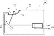
- FIG. 1 is a partial schematic cross-sectional view for explaining a head-up display device according to an embodiment of the present invention.
- the head-up display device 100 includes a display cell 11 and a first polarizing plate 12 with a retardation layer, and a display 10 for emitting projection light; and at least one reflector for reflecting the projection light (in the illustrated example, A housing 30 having one reflector 20) and an opening 32 and accommodating the display 10 and the reflector 20 therein; a cover member 40 covering the opening 32; a housing of the cover member 40 And a second polarizing plate with retardation layer 50 provided on the inner side.
- one reflector 20 is provided in the embodiment of FIG. 1, two reflectors 20, 22 may be provided as in the head-up display device 101 shown in FIG.
- any appropriate configuration may be employed as the display 10.
- a liquid crystal display device is mentioned as a representative example of a display. Therefore, as the display cell 11, a liquid crystal cell can be mentioned. Any appropriate configuration may be employed as a configuration of the liquid crystal cell (for example, a drive mode).
- the display 10 includes the display cell 11 and the first polarizing plate 12 with a retardation layer as described above.
- the first polarizing plate 12 with a retardation layer is typically bonded to the output side of the display cell 11 via an adhesive.
- the first retardation layer-provided polarizing plate 12 includes a polarizer 124 and a first retardation layer 126 in order from the display cell 11 side.
- the first retardation layer polarizing plate 12 may include a substrate 122 on the display cell 11 side of the polarizer 124 as necessary.
- the in-plane retardation Re (550) of the first retardation layer 126 is 100 nm to 200 nm.
- nx is the refractive index in the direction in which the in-plane refractive index is maximized (ie, the slow axis direction), and “ny” is the direction orthogonal to the in-plane slow axis (ie, the phase advance Axial refractive index).
- the reflector 20 has, for example, a mirror portion and a mirror holder for holding the mirror portion at a predetermined position of the housing 30.
- the mirror portion may be a plane mirror or a concave mirror.
- a concave mirror is employed.
- the projected image can be enlarged and displayed.
- the radius of curvature of the concave mirror can be appropriately set according to the purpose, the size of the image to be projected, and the like.
- the reflector 22 may be, for example, a flat mirror (cold mirror) that transmits only infrared light and reflects visible light and ultraviolet light.
- the housing 30 is a box-like member having an internal space capable of housing the display 10 and the reflectors 20 and 22.
- the housing 30 typically has an opening 32, and projection light emitted from the display 10 through the opening 32 is emitted to the outside of the housing 30.
- Housing 30 may be comprised of any suitable material.
- a material which is difficult to heat up by irradiation of sunlight and is easy to form can be mentioned. Specific examples of such materials include acrylic resins, epoxy resins, polyester resins, urethane resins, polyolefin resins, fluorine resins, and phenoxy resins.
- the housing 30 may be incorporated in part of a car or may be a member independent of the car. For example, a dashboard of a car may be used as the housing.
- the cover member 40 is a plate-like member that covers the opening 32 of the housing 30 so that dust does not enter the inside of the housing 30.
- the cover member 40 is typically transparent, and projection light reflected from the reflector 20 is transmitted through the cover member 40 and emitted to the outside of the housing 30. Details of the cover member will be described later in Section B.
- the second polarizing plate 50 with a retardation layer is bonded to the inside of the cover member 40 via the adhesive.
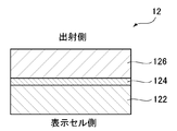
- the second polarizing plate with retardation layer 50 includes a polarizer 54 and a second retardation layer 56 in order from the cover member 40 side.
- the second retardation layer polarizing plate 50 may include a substrate 52 on the cover member 40 side of the polarizer 54 as necessary.
- the in-plane retardation Re (550) of the second retardation layer 56 is 100 nm to 200 nm.
- the angle between the slow axis of the second retardation layer and the absorption axis of the polarizer is a predetermined angle (described later: particularly preferably 45) By setting it in the vicinity of °), it has a function of converting linearly polarized light into circularly polarized light or elliptically polarized light, or a function of converting circularly polarized light or elliptically polarized light into linearly polarized light.
- projection light (circularly polarized light or elliptically polarized light) emitted from the display (liquid crystal display device) can be favorably converted into linearly polarized light and emitted to the outside of the housing 30.
- natural light from the outside is converted into circularly polarized light or elliptically polarized light by the second retardation layer, and when the circularly polarized light or elliptically polarized light is reflected inside the housing, the rotational direction is reversed.
- Such reflected (rotationally reversed) circularly polarized light or elliptically polarized light may be absorbed by the second retardation layer, and emission to the outside of the housing may be substantially prevented.
- the brightness of the projection light from the display released to the outside of the housing can be maintained high, and the visibility inside the housing is significantly reduced (that is, the concealability inside the housing is extremely reduced) Be excellent).
- the first polarizing plate with retardation layer (first retardation layer) and the second polarizing plate with retardation layer (second retardation layer) are respectively placed at predetermined positions in the head-up display device.
- first retardation layer first retardation layer
- second retardation layer the second retardation layer-attached polarizing plate.
- the details of the second retardation layer-attached polarizing plate will be described later in Section C together with the first retardation layer-attached polarizing plate.
- the absorption axes of the respective polarizers are substantially parallel to each other in the first retardation-layer-attached polarizing plate and the second retardation-layer-attached polarizing plate.
- the first retardation layer polarizing plate and the second retardation layer polarizing plate are typically arranged such that the slow axes of the respective retardation layers are substantially orthogonal to each other. .
- the expressions “substantially parallel” and “substantially parallel” include cases where an angle formed by two directions is 0 ° ⁇ 7 °, preferably 0 ° ⁇ 5 °. More preferably, it is 0 ° ⁇ 3 °.
- the expressions “substantially orthogonal” and “substantially orthogonal” include cases where the angle formed by the two directions is 90 ° ⁇ 7 °, preferably 90 ° ⁇ 5 °, more preferably 90 ° ⁇ . It is 3 degrees.
- orthogonal or “parallel”
- the mirror holder has, for example, an axis whose circumferential surface is connected to the back surface of the mirror, and a controller connected to the end of the axis. Since the angle of the mirror unit changes in accordance with the rotation of the shaft, the control unit can indirectly adjust the angle of the mirror unit by controlling the rotation of the shaft. The angle of the mirror may typically be adjusted according to the shape of the windshield.
- the head-up display device will not be described because any suitable configuration commonly used in the industry is adopted.
- the cover member and the polarizing plate with a retardation layer will be specifically described.
- the cover member 40 is typically transparent, as described above.
- “transparent” means having the property of transmitting visible light with a wavelength of 360 nm to 830 nm. Transparent substantially does not absorb visible light and transmits light of all wavelengths in the visible light range (colorless and transparent), and absorbs light of a part of wavelengths in the visible light range, and its wavelengths Other cases of transmitting light (colored and transparent) are included.
- the cover member 40 is preferably colorless and transparent.
- the total light transmittance of the cover member is preferably 50% or more, more preferably 70% or more, and still more preferably 90% or more. The total light transmittance is a value measured according to JIS K7375.
- the thickness of the cover member may be, for example, 10 ⁇ m to 1000 ⁇ m. If the cover member is too thick, the transmittance of the projection light may be reduced (the light loss of the projection light may be increased), which may contribute to the generation of a double image. If the cover member is too thin, the mechanical strength may be insufficient and the covering function may be insufficient.
- the cover member may be composed of any suitable transparent material. Typical examples include resin and glass. Specific examples of the resin include: ester-based resins such as polyethylene terephthalate and polyethylene naphthalate; cellulose-based resins such as diacetyl cellulose and triacetyl cellulose; polycarbonate-based resins such as bisphenol A-based polycarbonate; acrylic resins such as polymethyl methacrylate Acrylic resins such as lactone-modified acrylic resin; styrene resins such as polystyrene and acrylonitrile / styrene copolymer; polyethylene, polypropylene, olefin resins having cyclic structure or norbornene structure, and olefin resin such as ethylene / propylene copolymer Vinyl-based resins; amide-based resins such as aromatic polyamides; imide-based resins; sulfone-based resins; polyethersulfone-based resins; Rensurufido resin
- first Retardation Layer Polarizing Plate and Second Retardation Layer Polarizing Plate The constituent elements of the first retardation layer polarizing plate and the second retardation layer polarizing plate (typically, polarization).
- the same explanation applies to the elements 124 and 54, the first retardation layer 126 and the second retardation layer 56, and the substrates 122 and 52).
- the polarizers 124 and 54 may be identical to or different from each other. The same applies to the first retardation layer 56 and the second retardation layer 126, and to the substrates 122 and 52.
- Polarizer Any appropriate polarizer may be employed as the polarizer. Representative examples include iodine-based polarizers and lyotropic liquid crystal polarizers.
- the resin film forming the iodine-based polarizer may be a single-layer resin film, or may be produced using a laminate of two or more layers.
- the polarizer composed of a single-layer resin film examples include polyvinyl alcohol (PVA) based resin film, partially formalized PVA based resin film, ethylene / vinyl acetate copolymer based partially saponified film, etc.
- PVA polyvinyl alcohol
- a polarizer obtained by dyeing a PVA-based resin film with iodine and uniaxially stretching it is used because of excellent optical properties.
- staining by the said iodine is performed by immersing a PVA-type resin film in iodine aqueous solution, for example.
- the stretching ratio of the uniaxial stretching is preferably 3 to 7 times. Stretching may be carried out after the dyeing process or may be carried out while dyeing. Moreover, it may be dyed after being drawn.
- the PVA resin film is subjected to swelling treatment, crosslinking treatment, washing treatment, drying treatment, and the like. For example, by immersing and washing the PVA-based resin film in water prior to dyeing, it is possible not only to clean the stains and antiblocking agents on the surface of the PVA-based resin film, but also to swell the PVA-based resin film and dye it. Unevenness can be prevented.
- the polarizer obtained by using a laminate a laminate of a resin substrate and a PVA-based resin layer (PVA-based resin film) laminated on the resin substrate, or a resin substrate and the resin
- coated-formed to the base material is mentioned.
- coated and formed by the said resin base material applies a PVA-type resin solution to a resin base material, for example, it is made to dry, and a resin base material Forming a PVA-based resin layer thereon to obtain a laminate of the resin base and the PVA-based resin layer; stretching and dyeing the laminate to make the PVA-based resin layer as a polarizer; obtain.
- stretching typically includes dipping the laminate in a boric acid aqueous solution and stretching.
- stretching may optionally further comprise air-stretching the laminate at a high temperature (eg, 95 ° C. or higher) prior to stretching in an aqueous boric acid solution.
- the resulting laminate of resin substrate / polarizer may be used as it is (that is, the resin substrate may be used as a protective layer of polarizer), and the resin substrate is peeled off from the laminate of resin substrate / polarizer.
- any appropriate protective layer depending on the purpose may be laminated on the peeled surface.
- the details of the method for producing such a polarizer are described, for example, in JP-A-2012-73580. The publication is incorporated herein by reference in its entirety.
- the lyotropic liquid crystal polarizer is excellent in heat resistance, and as a result, the heat resistance of the head-up display device can be further improved.
- the lyotropic liquid crystal polarizer includes, for example, an aromatic disazo compound represented by the following formula (1):
- Q 1 represents a substituted or unsubstituted aryl group
- Q 2 represents a substituted or unsubstituted arylene group
- R 1 each independently represents a hydrogen atom, a substituted or unsubstituted group
- R represents an alkyl group, substituted or unsubstituted acetyl group, substituted or unsubstituted benzoyl group, substituted or unsubstituted phenyl group
- M represents a counter ion
- m is an integer of 0 to 2
- n is 0
- at least one of m and n is not 0, 1 ⁇ m + n ⁇ 6, and when m is 2, each R 1 may be the same or
- the naphthyl group and the azo group are bonded at the 1- or 2-position of the naphthyl group.
- R 1 is preferably a hydrogen atom, a substituted or unsubstituted alkyl group, or a substituted or unsubstituted acetyl group, more preferably a hydrogen atom.
- the substituted or unsubstituted alkyl group includes a substituted or unsubstituted alkyl group having 1 to 6 carbon atoms.
- M (counter ion) of the formula (1) is preferably a hydrogen ion; an alkali metal ion such as Li, Na, K or Cs; an alkaline earth metal ion such as Ca, Sr or Ba; other metal ions; And ammonium ions optionally substituted by a group or a hydroxyalkyl group; salts of organic amines and the like.
- metal ions include Ni + , Fe 3 + , Cu 2 + , Ag 2 + , Zn 2 + , Al 3 + , Pd 2 + , Cd 2 + , Sn 2 + , Co 2 + , Mn 2 + , Ce 3 + .
- the aryl group represented by Q 1 in the formula (1) includes, in addition to a phenyl group, a fused ring group in which two or more benzene rings such as a naphthyl group are condensed.
- the arylene group represented by Q 2 includes, in addition to a phenylene group, a fused ring group in which two or more benzene rings such as a naphthylene group are fused.
- the aryl group of Q 1 or the arylene group of Q 2 may or may not have a substituent.
- the aromatic disazo compound of the formula (1) having a polar group is excellent in solubility in an aqueous solvent, regardless of whether the aryl group or the arylene group is substituted or unsubstituted.
- the substituent is one selected from an alkoxy group having 1 to 6 carbon atoms, a hydroxyalkyl group having 1 to 6 carbon atoms, a carboxyl group, a sulfonic acid group, and a nitro group.
- the aromatic disazo compound which has such a substituent is especially excellent in water solubility.
- the aryl group or arylene group may be substituted by one of these substituents, or may be substituted by two or more. Also, the substituents may be substituted in any ratio.
- Q 1 in the formula (1) is preferably a substituted or unsubstituted phenyl group, more preferably a phenyl group having the above-mentioned substituent.
- Q 2 is preferably a substituted or unsubstituted naphthylene group, more preferably a naphthylene group having the above-described substituent, and particularly preferably a 1,4-naphthylene group having the above-described substituent.
- R 1 , M, m and n are as described for Formula (1) above.
- a and B represent a substituent, and a and b represent the substitution number.
- a and B are each independently an alkyl group having 1 to 6 carbon atoms, an alkoxy group having 1 to 6 carbon atoms, an alkylamino group having 1 to 6 carbon atoms, a phenylamino group, an acylamino group having 1 to 6 carbon atoms And a hydroxyalkyl group having 1 to 6 carbon atoms such as a dihydroxypropyl group, a carboxyl group such as a COOM group, a sulfonic acid group such as an SO 3 M group, a hydroxyl group, a cyano group, a nitro group, an amino group and a halogeno group.
- a is an integer of 0 to 5
- b is an integer of 0 to 4. However, at least one of a and b is not zero.
- the substituents A may be the same or different.
- the substituents B may be the same or different.
- aromatic disazo compounds represented by the following formula (3) are preferable.
- the OH group of the naphthyl group is bonded to the position (ortho position) adjacent to the azo group.
- R 1 , M, m and n are as described for Formula (1), and A is as described for Formula (2).
- p represents an integer of 0 to 4. p is preferably 1 or 2, more preferably 1.
- the aromatic disazo compounds represented by the above formulas (1) to (3) can be produced, for example, by Toyo Hosoda "Theoretical manufacture dye chemistry (5th edition)" (July 15, 1947, published by Jichihodo, pages 135 to 152). Can be synthesized according to For example, after the aromatic disazo compound of the formula (3) is subjected to diazotization and coupling reaction of an aniline derivative and a naphthalenesulfonic acid derivative to obtain a monoazo compound, this monoazo compound is diazotized and further 1-amino- It can be synthesized by coupling reaction with an 8-naphthol sulfonic acid derivative.
- the lyotropic liquid crystal polarizer can be produced, for example, by a method including the following step B and step C.
- the step A may be performed before the step B, and the step D may be performed after the step C.
- Step A a step of subjecting the surface of the substrate to an orientation treatment.
- Step B A step of applying a coating solution containing the aromatic disazo compound represented by the above formula (1) on the surface of a substrate to form a coating.
- Step C A step of drying the coated film to form a polarizer which is a dried coated film.
- Process D A process of subjecting the surface of the polarizer obtained in Process C to a water resistance treatment.
- the polarizing plate with a retardation layer which has an orientation film between a base material and a polarizer is produced.
- the substrate may be used as it is (in this case, the substrate may function as a protective layer of a polarizer), and the substrate may be peeled off to provide any appropriate protective film on the peeled surface.
- Process B is a process of forming a coating film using a coating liquid.
- the coating liquid contains the above-mentioned aromatic disazo compound and a solvent for dissolving or dispersing the aromatic disazo compound.
- the coating liquid is obtained by dissolving or dispersing the aromatic disazo compound in a solvent.
- any suitable solvent can be used as a solvent for dissolving or dispersing the aromatic disazo compound.
- Aqueous solvents are preferred.
- the aqueous solvent include water, a hydrophilic solvent, and a mixed solvent of water and a hydrophilic solvent.
- the hydrophilic solvent is a solvent which dissolves substantially uniformly in water.
- hydrophilic solvents include alcohols such as methanol and isopropyl alcohol; glycols such as ethylene glycol; cellosolves such as methyl cellosolve and ethyl cellosolve; ketones such as acetone and methyl ethyl ketone; esters such as ethyl acetate; It can be mentioned.
- the aqueous solvent preferably, water or a mixed solvent of water and a hydrophilic solvent is used.
- the aromatic disazo compound represented by the above formula (1) is an organic compound having lyotropic liquid crystallinity. Therefore, the coating liquid exhibits a lyotropic liquid crystal phase by changing the liquid temperature, the concentration of the aromatic disazo compound, and the like.
- the lyotropic liquid crystal phase is generated by the formation of a supramolecular association in the liquid by the aromatic disazo compound.
- the lyotropic liquid crystal phase can be identified and identified by the optical pattern observed with a polarizing microscope.
- the supramolecular association is one large complex formed by bonding a plurality of aromatic disazo compounds by hydrogen bond or the like.
- the (meth) acrylic resin has a Tg (glass transition temperature) of preferably 115 ° C. or more, more preferably 120 ° C. or more, still more preferably 125 ° C. or more, particularly preferably 130 ° C. or more. It is because it is excellent in durability.
- the upper limit of the Tg of the (meth) acrylic resin is not particularly limited, but is preferably 170 ° C. or less from the viewpoint of formability and the like.
- Retardation Layer-Containing Polarizing Plate The laminate of the base material / polarizer and the retardation film were pasted together so that the polarizer and the retardation film faced each other.
- an acrylic pressure-sensitive adhesive manufactured by Nitto Denko Corporation, product name “CS9861UA”
- bonding was performed such that the absorption axis of the polarizer and the slow axis of the retardation film form an angle of 45 °.
- a polarizing plate with a retardation layer having a constitution of base material / polarizer / retardation film (retardation layer) was obtained.
- Two polarizing plates with retardation layer were prepared, and it was set as the 1st polarizing plate with retardation layer and the 2nd polarizing plate with retardation layer.
- Example 2 A head-up display device compatible product was produced in the same manner as in Example 1 except that the retardation value of both the first retardation layer and the second retardation layer was 110 nm. The obtained product corresponding to the head-up display device was subjected to the same evaluation as in Example 1. The results are shown in Table 1.
- Example 4 A head-up display device compatible product was produced in the same manner as in Example 1 except that the retardation value of the first retardation layer was 120 nm, and the retardation value of the second retardation layer was 190 nm.
- the obtained product corresponding to the head-up display device was subjected to the same evaluation as in Example 1. The results are shown in Table 1.
- Comparative Example 1 A head-up display device compatible product was produced in the same manner as in Example 1 except that the first retardation layer was not provided. The obtained product corresponding to the head-up display device was subjected to the same evaluation as in Example 1. The results are shown in Table 1.
- Comparative Example 2 A head-up display device compatible product was produced in the same manner as in Example 1 except that neither the first retardation layer nor the second retardation layer was provided. The obtained product corresponding to the head-up display device was subjected to the same evaluation as in Example 1. The results are shown in Table 1.
- the head-up display device of the example satisfies the internal concealability and the display brightness at the same time.
Abstract
本発明は、内部の隠蔽性と表示輝度とを同時に満足し得るヘッドアップディスプレイ装置を提供することを目的とする。 本発明のヘッドアップディスプレイ装置(100)は、表示セル(11)と、表示セル(11)の出射側において表示セル側から順に偏光子および第1の位相差層を含む第1の位相差層付偏光板(12)と、を含み、投影光を出射する表示器(10)と;投影光を反射する少なくとも1つの反射器(20)と;開口部(32)を有し、かつ、表示器(10)および反射器(20)を内部に収容する筐体(30)と;開口部(32)を覆うカバー部材(40)と;カバー部材(40)の筐体内部側に設けられた、カバー部材側から順に偏光子と第2の位相差層とを含む第2の位相差層付偏光板(50)と;を有する。第1の位相差層および第2の位相差層の面内位相差Re(550)は、それぞれ100nm~200nmである。
Description
本発明は、ヘッドアップディスプレイ装置に関する。
車両の運転者は、フロントガラスを通して前方を注視すると共に、インストルメントパネル上の計器類を目視しながら運転を実施する。すなわち、視線が前方と下方の計器類とへ移動する。前方を見たままで、計器類を見ることができれば、視線の移動がなく、運転性(最終的に安全性)の向上が期待できる。この知見からヘッドアップディスプレイ装置が開発され、実用に供されるようになってきている。ヘッドアップディスプレイ装置においては、光学系が収納されるハウジング内への塵芥等の異物を防止するため、光路の開口部を覆うカバー部材が設けられる。さらに、ハウジング内の高温化を防止するため(具体的には、太陽光の入射を防止するため)、上記カバー部材に偏光板が貼り合わせられる場合がある(例えば、特許文献1)。従来のヘッドアップディスプレイ装置は、ハウジング内部の隠蔽性が不十分であり内部が見えてしまうので、商品価値も不十分である。一方、ヘッドアップディスプレイ装置の隠蔽性を高めようとすると、表示輝度が低下し、視認性が不十分になってしまう。
本発明は上記従来の課題を解決するためになされたものであり、その目的とするところは、内部の隠蔽性と表示輝度とを同時に満足し得るヘッドアップディスプレイ装置を提供することにある。
本発明のヘッドアップディスプレイ装置は、表示セルと、該表示セルの出射側において該表示セル側から順に偏光子および第1の位相差層を含む第1の位相差層付偏光板と、を含み、投影光を出射する表示器と;該投影光を反射する少なくとも1つの反射器と;開口部を有し、かつ、該表示器および該反射器を内部に収容する筐体と;該開口部を覆うカバー部材と;該カバー部材の筐体内部側に設けられた、該カバー部材側から順に偏光子と第2の位相差層とを含む第2の位相差層付偏光板と;を有する。該第1の位相差層および該第2の位相差層の面内位相差Re(550)は、それぞれ100nm~200nmである。
1つの実施形態においては、上記偏光子は、下記式(1)で表される芳香族ジスアゾ化合物を含む:

式(1)において、Q1は、置換または非置換のアリール基を表し、Q2は、置換または非置換のアリーレン基を表し、R1は、それぞれ独立して、水素原子、置換または非置換のアルキル基、置換または非置換のアセチル基、置換または非置換のベンゾイル基、置換または非置換のフェニル基を表し、Mは対イオンを表し、mは0~2の整数であり、nは0~6の整数であり;ただし、mおよびnの少なくとも一方は0でなく、1≦m+n≦6であり、mが2である場合、それぞれのR1は同一であってもよく異なっていてもよい。
1つの実施形態においては、上記偏光子の厚みは100nm~1000nmである。
1つの実施形態においては、上記ヘッドアップディスプレイ装置は、上記開口部を介して上記筐体から出射した投影光のフロントガラスに対する反射角が10°~50°となるよう構成されている。
1つの実施形態においては、上記偏光子は、下記式(1)で表される芳香族ジスアゾ化合物を含む:
1つの実施形態においては、上記偏光子の厚みは100nm~1000nmである。
1つの実施形態においては、上記ヘッドアップディスプレイ装置は、上記開口部を介して上記筐体から出射した投影光のフロントガラスに対する反射角が10°~50°となるよう構成されている。
本発明の実施形態によれば、ヘッドアップディスプレイ装置において、表示器の出射側に表示器の表示セル側から順に偏光子と第1の位相差層とを含む第1の位相差層付偏光板を積層し、かつ、筐体の開口部を覆うカバー部材の筐体内部側にカバー部材側から順に偏光子と第2の位相差層とを含む第2の位相差層付偏光板を積層することにより、内部の隠蔽性と表示輝度とを同時に満足し得るヘッドアップディスプレイ装置を実現することができる。
以下、本発明の実施形態について説明するが、本発明はこれらの実施形態には限定されない。
A.ヘッドアップディスプレイ装置の全体構成
図1は、本発明の1つの実施形態によるヘッドアップディスプレイ装置を説明する部分概略断面図である。ヘッドアップディスプレイ装置100は、表示セル11と第1の位相差層付偏光板12とを含み、投影光を出射する表示器10と;投影光を反射する少なくとも1つの反射器(図示例では、1つの反射器)20と;開口部32を有し、かつ、表示器10および反射器20を内部に収容する筐体30と;開口部32を覆うカバー部材40と;カバー部材40の筐体内部側に設けられた第2の位相差層付偏光板50と;を有する。図1の実施形態では1つの反射器20が設けられているが、図2に示すヘッドアップディスプレイ装置101のように2つの反射器20、22が設けられてもよい。
図1は、本発明の1つの実施形態によるヘッドアップディスプレイ装置を説明する部分概略断面図である。ヘッドアップディスプレイ装置100は、表示セル11と第1の位相差層付偏光板12とを含み、投影光を出射する表示器10と;投影光を反射する少なくとも1つの反射器(図示例では、1つの反射器)20と;開口部32を有し、かつ、表示器10および反射器20を内部に収容する筐体30と;開口部32を覆うカバー部材40と;カバー部材40の筐体内部側に設けられた第2の位相差層付偏光板50と;を有する。図1の実施形態では1つの反射器20が設けられているが、図2に示すヘッドアップディスプレイ装置101のように2つの反射器20、22が設けられてもよい。
表示器10としては、任意の適切な構成が採用され得る。表示器の代表例としては液晶表示装置が挙げられる。したがって、表示セル11としては、液晶セルが挙げられる。液晶セルの構成(例えば、駆動モード)としては、任意の適切な構成が採用され得る。
本発明の実施形態においては、表示器10は、上記のとおり表示セル11と第1の位相差層付偏光板12とを含む。第1の位相差層付偏光板12は、代表的には、粘着剤を介して表示セル11の出射側に貼り合わせられている。第1の位相差層付偏光板12は、図3に示すように、表示セル11側から順に偏光子124と第1の位相差層126とを含む。図示例のように、第1の位相差層付偏光板12は、偏光子124の表示セル11側に必要に応じて基材122を含んでいてもよい。本発明の実施形態においては、第1の位相差層126の面内位相差Re(550)は100nm~200nmである。第1の位相差層の面内位相差がこのような範囲であれば、第1の位相差層の遅相軸と偏光子の吸収軸との角度を所定の角度(後述)に設定することにより、表示器からの出射光を円偏光または楕円偏光に変換する機能を有する。このような出射光(円偏光または楕円偏光)は、後述する第2の位相差層付偏光板の第2の位相差層により直線偏光に変換され、開口部から筐体外部に放たれる。第1の位相差層付偏光板の詳細については、第2の位相差層付偏光板と併せてC項で後述する。なお、本明細書において「Re(λ)」は、23℃における波長λnmの光で測定したフィルムの面内位相差である。したがって、「Re(550)」は、23℃における波長550nmの光で測定したフィルムの面内位相差である。Re(λ)は、フィルムの厚みをd(nm)としたとき、式:Re=(nx-ny)×dによって求められる。ここで、「nx」は面内の屈折率が最大になる方向(すなわち、遅相軸方向)の屈折率であり、「ny」は面内で遅相軸と直交する方向(すなわち、進相軸方向)の屈折率である。
反射器20(および存在する場合には反射器22)としては、任意の適切な構成が採用され得る。反射器20は、例えば、鏡部と当該鏡部を筐体30の所定の位置で保持するミラーホルダーとを有する。鏡部は、平面鏡であってもよく凹面鏡であってもよい。図示例では凹面鏡が採用されている。凹面鏡を用いることにより、投影される映像を拡大して表示することができる。凹面鏡の曲率半径は、目的、投影させる映像の大きさなどに応じて適切に設定され得る。反射器22が設けられる場合、反射器22は、例えば、赤外線のみを透過しかつ可視光線および紫外線を反射する平面鏡(コールドミラー)であり得る。
筐体30は、表示器10および反射器20、22を収容可能な内部空間を有する箱状の部材である。筐体30は、代表的には開口部32を有し、この開口部32を介して表示器10から出射された投影光が筐体30の外部に放たれる。筐体30は、任意の適切な材料で構成され得る。好ましい構成材料としては、太陽光の照射によって昇温し難くかつ成形し易い材料が挙げられる。このような材料の具体例としては、アクリル系樹脂、エポキシ系樹脂、ポリエステル系樹脂、ウレタン系樹脂、ポリオレフィン系樹脂、フッ素系樹脂、フェノキシ系樹脂が挙げられる。筐体30は自動車の一部に組み込まれていてもよく、自動車と独立した部材であってもよい。例えば、自動車のダッシュボードを筐体として用いてもよい。
カバー部材40は、筐体30の内部に塵芥が入らないように筐体30の開口部32を覆う板状の部材である。カバー部材40は、代表的には透明であり、反射器20から反射された投影光は、カバー部材40を透過して筐体30の外部に放たれる。カバー部材の詳細についてはB項で後述する。
本発明の実施形態においては、第2の位相差層付偏光板50が、粘着剤を介してカバー部材40の筐体内部側に貼り合わせられている。第2の位相差層付偏光板50は、図4に示すように、カバー部材40側から順に偏光子54と第2の位相差層56とを含む。図示例のように、第2の位相差層付偏光板50は、偏光子54のカバー部材40側に必要に応じて基材52を含んでいてもよい。本発明の実施形態においては、第2の位相差層56の面内位相差Re(550)は100nm~200nmである。第2の位相差層の面内位相差がこのような範囲であれば、第2の位相差層の遅相軸と偏光子の吸収軸との角度を所定の角度(後述:とりわけ好ましくは45°近傍)に設定することにより、直線偏光を円偏光または楕円偏光に変換する機能、あるいは、円偏光または楕円偏光を直線偏光に変換する機能を有する。その結果、表示器(液晶表示装置)から出射される投影光(円偏光または楕円偏光)を良好に直線偏光に変換し、筐体30の外部に放つことができる。さらに、第2の位相差層により、外部からの自然光は円偏光または楕円偏光に変換され、当該円偏光または楕円偏光が筐体内部で反射すると回転方向が逆転する。このような反射した(回転方向が逆転した)円偏光または楕円偏光は、第2の位相差層で吸収され、筐体外部への放出が実質的に防止され得る。その結果、筐体外部へ放たれる表示器からの投影光の輝度を高く維持することができ、かつ、筐体内部の視認性を格段に小さくする(すなわち、筐体内部の隠蔽性を非常に優れたものとする)ことができる。言い換えれば、第1の位相差層付偏光板(第1の位相差層)と第2の位相差層付偏光板(第2の位相差層)とをそれぞれヘッドアップディスプレイ装置の所定の位置に所定の状態で組み込むことにより、内部の隠蔽性と表示輝度とを同時に満足し得るヘッドアップディスプレイ装置を実現することができる。さらに、第2の位相差層付偏光板を配置することにより、第2の位相差層付偏光板の偏光子によって太陽光の入射(透過)を抑制することができるので、ヘッドアップディスプレイ装置の耐熱性を向上させることができる。第2の位相差層付偏光板の詳細については、第1の位相差層付偏光板と併せてC項で後述する。
本発明の実施形態においては、第1の位相差層付偏光板と第2の位相差層付偏光板とは、代表的には、それぞれの偏光子の吸収軸が実質的に平行となるように配置されている。さらに、第1の位相差層付偏光板と第2の位相差層付偏光板とは、代表的には、それぞれの位相差層の遅相軸が実質的に直交するように配置されている。第1の位相差層付偏光板と第2の位相差層付偏光板とをこのような軸角度となるよう配置することにより、2つの位相差層付偏光板による直線偏光と円偏光または楕円偏光との相互の変換機能を十分なものとすることができる。なお、本明細書において「実質的に平行」および「略平行」という表現は、2つの方向のなす角度が0°±7°である場合を包含し、好ましくは0°±5°であり、さらに好ましくは0°±3°である。「実質的に直交」および「略直交」という表現は、2つの方向のなす角度が90°±7°である場合を包含し、好ましくは90°±5°であり、さらに好ましくは90°±3°である。さらに、本明細書において単に「直交」または「平行」というときは、実質的に直交または実質的に平行な状態を含み得るものとする。
ヘッドアップディスプレイ装置は、1つの実施形態においては、図5に示すように、開口部32を介して筐体30から出射した投影光のフロントガラス60に対する反射角αが10°~50°となるよう構成されている。このような構成であれば、上記第1および第2の位相差層付偏光板の効果との相乗的な効果により、より優れた内部の隠蔽性とより優れた表示輝度とを有するヘッドアップディスプレイ装置を実現することができる。反射角αは、好ましくは15°~45°であり、より好ましくは20°~40°である。反射角αは、反射器20の角度を調整することにより制御することができる。具体的には、ミラーホルダーを角度調整可能な構成とすればよい。ミラーホルダーは、例えば、鏡部の裏面にその周面が接続された軸と、軸の端部と接続した制御部と、を有する。鏡部の角度は、軸の回転に追従して変化するので、制御部によって軸の回転を制御することにより、間接的に鏡部の角度を調整することができる。鏡部の角度は、代表的には、フロントガラスの形状に応じて調整され得る。
ヘッドアップディスプレイ装置の詳細な構成については、業界で慣用されている任意の適切な構成が採用されるので、詳細な説明は省略する。以下、カバー部材および位相差層付偏光板について具体的に説明する。
B.カバー部材
カバー部材40は、上記のとおり、代表的には透明である。本明細書において「透明」とは、波長360nm~830nmの可視光を透過する性質を有することを意味する。透明は、実質的に可視光を吸収せず、可視光域の全ての波長の光を透過する場合(無色透明)、および、可視光域の一部の波長の光を吸収し、かつその波長以外の光を透過する場合(有色透明)を含む。カバー部材40は、好ましくは無色透明である。カバー部材の全光線透過率は、好ましくは50%以上であり、より好ましくは70%以上であり、さらに好ましくは90%以上である。全光線透過率は、JIS K7375に準じて測定される値である。
カバー部材40は、上記のとおり、代表的には透明である。本明細書において「透明」とは、波長360nm~830nmの可視光を透過する性質を有することを意味する。透明は、実質的に可視光を吸収せず、可視光域の全ての波長の光を透過する場合(無色透明)、および、可視光域の一部の波長の光を吸収し、かつその波長以外の光を透過する場合(有色透明)を含む。カバー部材40は、好ましくは無色透明である。カバー部材の全光線透過率は、好ましくは50%以上であり、より好ましくは70%以上であり、さらに好ましくは90%以上である。全光線透過率は、JIS K7375に準じて測定される値である。
カバー部材の表面形状は、開口部32の形状に応じて適切に設計することができる。例えば、カバー部材は、開口部を覆う部分が、平面のみまたは曲面のみから構成されていてもよく、開口部を覆う部分が、複数の平面および/または複数の曲面から構成されてもよい。代表的には、カバー部材の表面形状は、平面のみまたは曲面のみから構成されている。図示例では、開口部を覆う部分が曲面のみで構成されたカバー部材が用いられている。
カバー部材の厚みは、例えば10μm~1000μmであり得る。カバー部材が厚すぎると、投影光の透過率が低減し(投影光の光損失が多くなり)、さらに、二重像が発生する一因となるおそれがある。カバー部材が薄すぎると、機械的強度が不十分となり、被覆機能が不十分となるおそれがある。
カバー部材は、任意の適切な透明材料で構成され得る。代表例としては、樹脂、ガラスが挙げられる。樹脂の具体例としては、ポリエチレンテレフタレート、ポリエチレンナフタレート等のエステル系樹脂;ジアセチルセルロース、トリアセチルセルロース等のセルロース系樹脂;ビスフェノールA系ポリカーボネートなどのポリカーボネート系樹脂;ポリメチルメタクリレート等のアクリル系樹脂、ラクトン変性アクリル樹脂などのアクリル系樹脂;ポリスチレン、アクリロニトリル・スチレン共重合体等のスチレン系樹脂;ポリエチレン、ポリプロピレン、環状構造又はノルボルネン構造を有するポリオレフィン、エチレン・プロピレン共重合体等のオレフィン系樹脂;塩化ビニル系樹脂;芳香族ポリアミド等のアミド系樹脂;イミド系樹脂;スルホン系樹脂;ポリエーテルスルホン系樹脂;ポリエーテルエーテルケトン系樹脂、ポリフェニレンスルフィド系樹脂;ビニルアルコール系樹脂;塩化ビニリデン系樹脂;ビニルブチラール系樹脂;アリレート系樹脂;ポリオキシメチレン系樹脂;エポキシ系樹脂;が挙げられる。これらの樹脂は、単独で用いてもよく、2種以上を組み合わせて用いてもよい。
C.第1の位相差層付偏光板および第2の位相差層付偏光板
第1の位相差層付偏光板および第2の位相差層付偏光板のそれぞれの構成要素(代表的には、偏光子124および54、第1の位相差層126および第2の位相差層56、基材122および52)については、同様の説明が適用されるので、区別して記載する必要がある場合を除きまとめて説明する。なお、例えば偏光子124および54は、それぞれが同一であってもよく異なっていてもよい。第1の位相差層56および第2の位相差層126、ならびに、基材122および52についても同様である。
第1の位相差層付偏光板および第2の位相差層付偏光板のそれぞれの構成要素(代表的には、偏光子124および54、第1の位相差層126および第2の位相差層56、基材122および52)については、同様の説明が適用されるので、区別して記載する必要がある場合を除きまとめて説明する。なお、例えば偏光子124および54は、それぞれが同一であってもよく異なっていてもよい。第1の位相差層56および第2の位相差層126、ならびに、基材122および52についても同様である。
C-1.偏光子
偏光子としては、任意の適切な偏光子が採用され得る。代表例としては、ヨウ素系偏光子およびリオトロピック液晶偏光子が挙げられる。
偏光子としては、任意の適切な偏光子が採用され得る。代表例としては、ヨウ素系偏光子およびリオトロピック液晶偏光子が挙げられる。
ヨウ素系偏光子を形成する樹脂フィルムは、単層の樹脂フィルムであってもよく、二層以上の積層体を用いて作製されてもよい。
単層の樹脂フィルムから構成される偏光子の具体例としては、ポリビニルアルコール(PVA)系樹脂フィルム、部分ホルマール化PVA系樹脂フィルム、エチレン・酢酸ビニル共重合体系部分ケン化フィルム等の親水性高分子フィルムに、ヨウ素や二色性染料等の二色性物質による染色処理および延伸処理が施されたもの、PVAの脱水処理物やポリ塩化ビニルの脱塩酸処理物等ポリエン系配向フィルム等が挙げられる。好ましくは、光学特性に優れることから、PVA系樹脂フィルムをヨウ素で染色し一軸延伸して得られた偏光子が用いられる。
上記ヨウ素による染色は、例えば、PVA系樹脂フィルムをヨウ素水溶液に浸漬することにより行われる。上記一軸延伸の延伸倍率は、好ましくは3~7倍である。延伸は、染色処理後に行ってもよいし、染色しながら行ってもよい。また、延伸してから染色してもよい。必要に応じて、PVA系樹脂フィルムに、膨潤処理、架橋処理、洗浄処理、乾燥処理等が施される。例えば、染色の前にPVA系樹脂フィルムを水に浸漬して水洗することで、PVA系樹脂フィルム表面の汚れやブロッキング防止剤を洗浄することができるだけでなく、PVA系樹脂フィルムを膨潤させて染色ムラなどを防止することができる。
積層体を用いて得られる偏光子の具体例としては、樹脂基材と当該樹脂基材に積層されたPVA系樹脂層(PVA系樹脂フィルム)との積層体、あるいは、樹脂基材と当該樹脂基材に塗布形成されたPVA系樹脂層との積層体を用いて得られる偏光子が挙げられる。樹脂基材と当該樹脂基材に塗布形成されたPVA系樹脂層との積層体を用いて得られる偏光子は、例えば、PVA系樹脂溶液を樹脂基材に塗布し、乾燥させて樹脂基材上にPVA系樹脂層を形成して、樹脂基材とPVA系樹脂層との積層体を得ること;当該積層体を延伸および染色してPVA系樹脂層を偏光子とすること;により作製され得る。本実施形態においては、延伸は、代表的には積層体をホウ酸水溶液中に浸漬させて延伸することを含む。さらに、延伸は、必要に応じて、ホウ酸水溶液中での延伸の前に積層体を高温(例えば、95℃以上)で空中延伸することをさらに含み得る。得られた樹脂基材/偏光子の積層体はそのまま用いてもよく(すなわち、樹脂基材を偏光子の保護層としてもよく)、樹脂基材/偏光子の積層体から樹脂基材を剥離し、当該剥離面に目的に応じた任意の適切な保護層を積層して用いてもよい。このような偏光子の製造方法の詳細は、例えば特開2012-73580号公報に記載されている。当該公報は、その全体の記載が本明細書に参考として援用される。
リオトロピック液晶偏光子は耐熱性に優れるので、結果として、ヘッドアップディスプレイ装置の耐熱性をさらに向上させることができる。リオトロピック液晶偏光子は、例えば、下記式(1)で表される芳香族ジスアゾ化合物を含む:
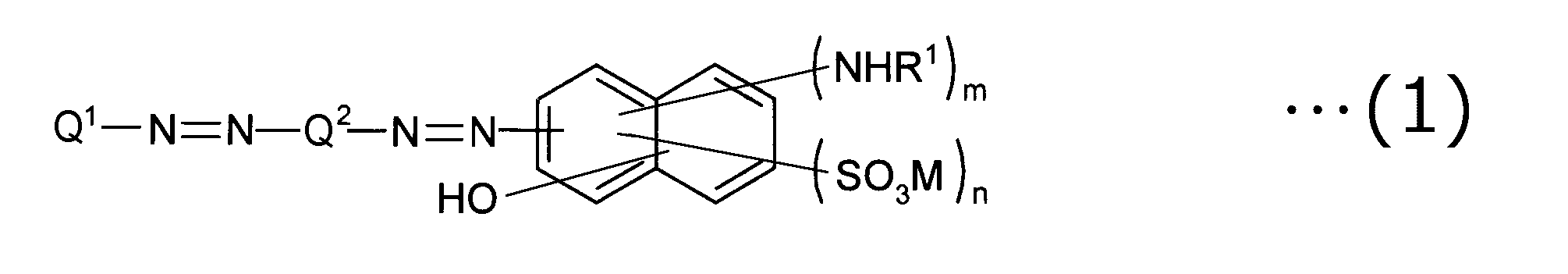
式(1)において、Q1は、置換または非置換のアリール基を表し、Q2は、置換または非置換のアリーレン基を表し、R1は、それぞれ独立して、水素原子、置換または非置換のアルキル基、置換または非置換のアセチル基、置換または非置換のベンゾイル基、置換または非置換のフェニル基を表し、Mは対イオンを表し、mは0~2の整数であり、nは0~6の整数であり;ただし、mおよびnの少なくとも一方は0でなく、1≦m+n≦6であり、mが2である場合、それぞれのR1は同一であってもよく異なっていてもよい。
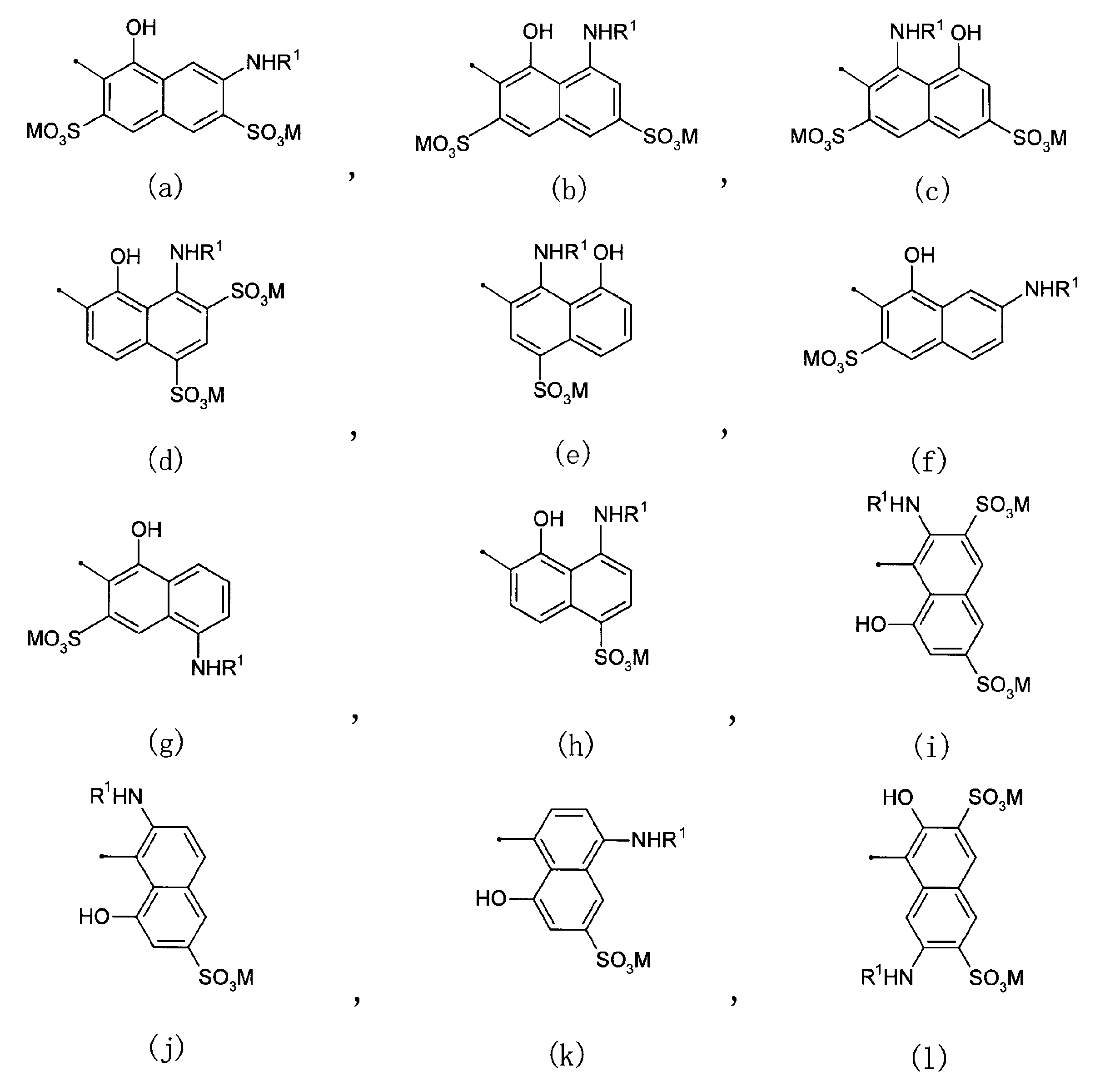
式(1)に示されたOH、(NHR1)m、および(SO3M)nは、それぞれナフチル環の7つの置換部位のいずれに結合していてもよい。
式(1)のナフチル基とアゾ基(-N=N-)の結合位置は、特に限定されない。好ましくは、ナフチル基とアゾ基とは、ナフチル基の1位または2位で結合されている。
式(1)のR1のアルキル基、アセチル基、ベンゾイル基、またはフェニル基が置換基を有する場合、その置換基としては、下記アリール基またはアリーレン基において例示する置換基が挙げられる。R1は、好ましくは、水素原子、置換または非置換のアルキル基、置換または非置換のアセチル基であり、より好ましくは水素原子である。置換または非置換のアルキル基としては、置換または非置換の炭素数1~6のアルキル基が挙げられる。
式(1)のM(対イオン)は、好ましくは、水素イオン;Li、Na、K、Csなどのアルカリ金属イオン;Ca、Sr、Baなどのアルカリ土類金属イオン;その他の金属イオン;アルキル基若しくはヒドロキシアルキル基で置換されていてもよいアンモニウムイオン;有機アミンの塩などが挙げられる。金属イオンとしては、例えば、Ni+、Fe3+、Cu2+、Ag+、Zn2+、Al3+、Pd2+、Cd2+、Sn2+、Co2+、Mn2+、Ce3+が挙げられる。有機アミンとしては、炭素数1~6のアルキルアミン、ヒドロキシル基を有する炭素数1~6のアルキルアミン、カルボキシル基を有する炭素数1~6のアルキルアミンなどが挙げられる。式(1)において、SO3Mが2つ以上存在する場合、それぞれのMは、同一でもよく異なっていてもよい。また、式(1)において、SO3MのMが2価以上の陽イオンである場合、隣接する他のアゾ系化合物のSO3
-と結合して超分子会合体を形成し得る。
式(1)のmは、好ましくは1である。また、一般式(1)のnは、好ましくは1または2である。
式(1)のナフチル基の具体例としては、下記の式(a)~式(l)で表されるものが挙げられる。式(a)~式(l)のR1およびMは、式(1)について説明したとおりである。
式(1)においてQ1で表されるアリール基は、フェニル基の他、ナフチル基などのようなベンゼン環が2以上縮合した縮合環基が挙げられる。Q2で表されるアリーレン基は、フェニレン基の他、ナフチレン基などのようなベンゼン環が2以上縮合した縮合環基が挙げられる。
Q1のアリール基またはQ2のアリーレン基は、それぞれ置換基を有していてもよいし、置換基を有していなくてもよい。上記アリール基またはアリーレン基が置換または非置換のいずれの場合でも、極性基を有する式(1)の芳香族ジスアゾ化合物は、水系溶媒に対する溶解性に優れている。
上記アリール基またはアリーレン基が置換基を有する場合、その置換基としては、例えば、炭素数1~6のアルキル基、炭素数1~6のアルコキシ基、炭素数1~6のアルキルアミノ基、フェニルアミノ基、炭素数1~6のアシルアミノ基、ジヒドロキシプロピル基等の炭素数1~6のヒドロキシアルキル基、COOM基などのカルボキシル基、SO3M基などのスルホン酸基、水酸基、シアノ基、ニトロ基、アミノ基、ハロゲノ基などが挙げられる。好ましくは、上記置換基は、炭素数1~6のアルコキシ基、炭素数1~6のヒドロキシアルキル基、カルボキシル基、スルホン酸基、およびニトロ基から選択される1つである。このような置換基を有する芳香族ジスアゾ化合物は、特に水溶性に優れている。上記アリール基またはアリーレン基は、これらの置換基の1種で置換されていてもよく、2種以上で置換されていてもよい。また、置換基は、任意の比率で置換されていてもよい。
式(1)のQ1は、好ましくは置換または非置換のフェニル基であり、より好ましくは上記置換基を有するフェニル基である。Q2は、好ましくは置換または非置換のナフチレン基であり、より好ましくは上記置換基を有するナフチレン基であり、特に好ましくは上記置換基を有する1,4-ナフチレン基である。
式(1)のQ1が置換または非置換のフェニル基で、かつ、Q2が置換または非置換の1,4-ナフチレン基である芳香族ジスアゾ系化合物は、下記式(2)で表される。

式(2)において、R1、M、mおよびnは、上記式(1)について説明したとおりである。式(2)において、AおよびBは、置換基を表し、aおよびbは、その置換数を表す。AおよびBは、それぞれ独立して、炭素数1~6のアルキル基、炭素数1~6のアルコキシ基、炭素数1~6のアルキルアミノ基、フェニルアミノ基、炭素数1~6のアシルアミノ基、ジヒドロキシプロピル基等の炭素数1~6のヒドロキシアルキル基、COOM基などのカルボキシル基、SO3M基などのスルホン酸基、水酸基、シアノ基、ニトロ基、アミノ基、ハロゲノ基を表す。aは、0~5の整数であり、bは、0~4の整数を表す。ただし、aおよびbの少なくとも一方は0でない。aが2以上である場合、置換基Aは、同じでもよいし、異なっていてもよい。bが2以上である場合、置換基Bは、同じでもよいし、異なっていてもよい。
式(2)に含まれる芳香族ジスアゾ化合物の中では、下記式(3)で表される芳香族ジスアゾ化合物が好ましい。式(3)の芳香族ジスアゾ化合物は、置換基Aがアゾ基(-N=N-)を基準にしてパラ位に結合している。さらに、式(3)の芳香族ジスアゾ化合物は、そのナフチル基のOH基がアゾ基に隣接した位置(オルト位)に結合している。このような式(3)の芳香族ジスアゾ化合物を用いれば、加熱により収縮し難い偏光子を容易に形成することができる。

式(3)において、R1、M、mおよびnは、上記式(1)について説明したとおりであり、Aは、上記式(2)について説明したとおりである。式(3)において、pは、0~4の整数を表す。pは、好ましくは1または2であり、より好ましくは1である。
上記式(1)~(3)で表される芳香族ジスアゾ化合物は、例えば、細田豊著「理論製造 染料化学(5版)」(昭和43年7月15日技報堂発行、135頁~152頁)に従って合成できる。例えば、式(3)の芳香族ジスアゾ化合物は、アニリン誘導体とナフタレンスルホン酸誘導体とをジアゾ化およびカップリング反応させてモノアゾ化合物を得た後、このモノアゾ化合物をジアゾ化し、さらに、1-アミノ-8-ナフトールスルホン酸誘導体とカップリング反応させることによって合成できる。
リオトロピック液晶偏光子は、例えば、下記の工程Bおよび工程Cを含む方法によって製造することができる。必要に応じて、工程Bの前に工程Aを行ってもよく、工程Cの後に工程Dを行ってもよい。
工程A:基材の表面に、配向処理を施す工程。
工程B:基材の表面に上記式(1)で表される芳香族ジスアゾ化合物を含むコーティング液を塗布し、塗膜を形成する工程。
工程C:塗膜を乾燥し、乾燥塗膜である偏光子を形成する工程。
工程D:工程Cで得られた偏光子の表面に、耐水化処理を施す工程。
工程A:基材の表面に、配向処理を施す工程。
工程B:基材の表面に上記式(1)で表される芳香族ジスアゾ化合物を含むコーティング液を塗布し、塗膜を形成する工程。
工程C:塗膜を乾燥し、乾燥塗膜である偏光子を形成する工程。
工程D:工程Cで得られた偏光子の表面に、耐水化処理を施す工程。
(工程A)
工程Aは、基材の表面に配向処理を行うことで、基材の表面に配向規制力を付与する工程である。予め配向規制力を有する基材を用いる場合、工程Aを実施する必要はない。配向規制力の付与方法としては、例えば、(a)基材の表面をラビング処理する方法、(b)フィルムの表面にポリイミドなどの膜を形成し、その膜の表面をラビング処理して配向膜を形成する方法、(c)フィルムの表面に光反応性化合物からなる膜を形成し、その膜に光照射して配向膜を形成する方法が挙げられる。なお、(b)および(c)の方法を用いる場合、基材と偏光子の間に配向膜を有する位相差層付偏光板が作製される。基材はそのまま用いてもよく(この場合、基材が偏光子の保護層として機能し得る)、基材を剥離して当該剥離面に任意の適切な保護フィルムを設けてもよい。
工程Aは、基材の表面に配向処理を行うことで、基材の表面に配向規制力を付与する工程である。予め配向規制力を有する基材を用いる場合、工程Aを実施する必要はない。配向規制力の付与方法としては、例えば、(a)基材の表面をラビング処理する方法、(b)フィルムの表面にポリイミドなどの膜を形成し、その膜の表面をラビング処理して配向膜を形成する方法、(c)フィルムの表面に光反応性化合物からなる膜を形成し、その膜に光照射して配向膜を形成する方法が挙げられる。なお、(b)および(c)の方法を用いる場合、基材と偏光子の間に配向膜を有する位相差層付偏光板が作製される。基材はそのまま用いてもよく(この場合、基材が偏光子の保護層として機能し得る)、基材を剥離して当該剥離面に任意の適切な保護フィルムを設けてもよい。
(工程B)
工程Bは、コーティング液を用いて塗膜を形成する工程である。コーティング液は、上記芳香族ジスアゾ化合物と、芳香族ジスアゾ化合物を溶解または分散させる溶媒と、を含む。コーティング液は、溶媒に、芳香族ジスアゾ化合物を溶解または分散させることによって得られる。なお、必要に応じて、上記芳香族ジスアゾ化合物以外の他のポリマー、および/または添加剤などを溶媒に添加してもよい。
工程Bは、コーティング液を用いて塗膜を形成する工程である。コーティング液は、上記芳香族ジスアゾ化合物と、芳香族ジスアゾ化合物を溶解または分散させる溶媒と、を含む。コーティング液は、溶媒に、芳香族ジスアゾ化合物を溶解または分散させることによって得られる。なお、必要に応じて、上記芳香族ジスアゾ化合物以外の他のポリマー、および/または添加剤などを溶媒に添加してもよい。
芳香族ジスアゾ化合物を溶解または分散させる溶媒は、任意の適切な溶媒を用いることができる。水系溶媒が好ましい。水系溶媒としては、水、親水性溶媒、水と親水性溶媒の混合溶媒などが挙げられる。親水性溶媒は、水に略均一に溶解する溶媒である。親水性溶媒としては、例えば、メタノール、イソプロピルアルコールなどのアルコール類;エチレングリコールなどのグリコール類;メチルセロソルブ、エチルセロソルブなどのセロソルブ類;アセトン、メチルエチルケトンなどのケトン類;酢酸エチルなどのエステル類;が挙げられる。上記水系溶媒は、好ましくは、水、または、水と親水性溶媒の混合溶媒が用いられる。
上記式(1)で表される芳香族ジスアゾ化合物は、リオトロピック液晶性を有する有機化合物である。そのため、コーティング液は、液温や芳香族ジスアゾ化合物の濃度などを変化させることにより、リオトロピック液晶相を示す。リオトロピック液晶相は、芳香族ジスアゾ化合物が液中で超分子会合体を形成することによって生じる。リオトロピック液晶相は、偏光顕微鏡で観察される光学模様によって、確認、識別できる。なお、超分子会合体は、複数の芳香族ジスアゾ化合物が水素結合等によって結合して形成された1つの大きな複合体である。
コーティング液中における芳香族ジスアゾ化合物の濃度は、それが液晶相を示すように調製することが好ましい。コーティング液中における芳香族ジスアゾ化合物の濃度は、通常0.05重量%~50重量%であり、好ましくは0.5重量%~40重量%であり、より好ましくは1重量%~10重量%である。また、コーティング液は、適切なpHに調整される。コーティング液のpHは、好ましくは2~10程度、より好ましくは6~8程度である。さらに、コーティング液の温度は、好ましくは10℃~40℃、より好ましくは15℃~30℃に調整される。
コーティング液を基材の上に塗布することにより、塗膜が形成される。塗膜内において、芳香族ジスアゾ化合物は基材の配向規制力によって所定の方向に配向する。コーティング液の塗布方法としては、任意の適切なコータを用いた塗布方法を採用することができる。コータとしては、例えば、バーコータ、ロールコータ、スピンコータ、コンマコータ、グラビアコータ、エアーナイフコータ、ダイコータが挙げられる。
(工程C)
工程Cは、乾燥塗膜である偏光子を形成する工程である。基材の上に乾燥塗膜である偏光子を形成することで、基材と偏光子とを有する偏光板が得られる。
工程Cは、乾燥塗膜である偏光子を形成する工程である。基材の上に乾燥塗膜である偏光子を形成することで、基材と偏光子とを有する偏光板が得られる。
工程Bで得られた塗膜を乾燥することにより、塗膜に含まれる溶媒が揮発し、固形の芳香族ジスアゾ化合物を含む乾燥塗膜(リオトロピック液晶偏光子)が形成される。偏光子の内部において、芳香族ジスアゾ化合物は超分子会合体を形成したままその配向が固定されている。塗膜の乾燥方法としては、例えば、自然乾燥、強制的な乾燥が挙げられる。強制的な乾燥としては、例えば、減圧乾燥、加熱乾燥、減圧加熱乾燥が挙げられる。好ましくは、自然乾燥が用いられる。塗膜の乾燥時間は、乾燥温度や溶媒の種類によって、適宜設定され得る。例えば、自然乾燥の場合には、乾燥時間は、好ましくは1秒~120分であり、より好ましくは10秒~5分である。乾燥温度は、好ましくは10℃~100℃であり、より好ましくは10℃~90℃であり、特に好ましくは10℃~80℃である。なお、乾燥温度とは、塗膜の表面や内部の温度ではなく、塗膜を乾燥する雰囲気の温度を意味する。
(工程D)
工程Dは、偏光子に耐水化処理液を接触させることによって偏光子に耐水性を付与する工程である。偏光子を耐水化処理液に接触させる方法としては、任意の適切な方法が採用され得る。接触方法としては、(a)偏光子の表面に耐水化処理液を塗布する、(b)耐水化処理液が満たされた浴中に偏光板(偏光子)を浸漬する、(c)耐水化処理液が満たされた浴中に偏光板(偏光子)を通過させる、などの方法が挙げられる。前記(a)の耐水化処理液の塗布は、任意の適切なコータ、または、スプレーなどを用いて行われ得る。
工程Dは、偏光子に耐水化処理液を接触させることによって偏光子に耐水性を付与する工程である。偏光子を耐水化処理液に接触させる方法としては、任意の適切な方法が採用され得る。接触方法としては、(a)偏光子の表面に耐水化処理液を塗布する、(b)耐水化処理液が満たされた浴中に偏光板(偏光子)を浸漬する、(c)耐水化処理液が満たされた浴中に偏光板(偏光子)を通過させる、などの方法が挙げられる。前記(a)の耐水化処理液の塗布は、任意の適切なコータ、または、スプレーなどを用いて行われ得る。
耐水化処理液は、任意の適切な液体を用いることができる。耐水化処理液は、例えば、有機色素を架橋する機能を有する架橋剤と、その架橋剤を溶解または分散する溶媒と、を含む。架橋剤としては、例えば、有機窒素化合物を挙げることができ、溶媒としては、例えば、水系溶媒を挙げることができる。有機窒素化合物としては、その分子中に2個以上のカチオン性基(好ましくは、窒素原子を含むカチオン性基)を有する非環式の有機窒素化合物などが好ましく用いられる。非環式の有機窒素化合物(非環式の脂肪族窒素化合物)としては、例えば、アルキレンジアミンなどの脂肪族ジアミンまたはその塩;アルキレントリアミンなどの脂肪族トリアミンまたはその塩;アルキレンテトラアミンなどの脂肪族テトラアミンまたはその塩;アルキレンペンタアミンなどの脂肪族ペンタアミンまたはその塩;アルキレンエーテルジアミンなどの脂肪族エーテルジアミンまたはその塩などが挙げられる。水系溶媒としては、上記工程Bに関して説明したものを用いることができる。
耐水化処理液中における架橋剤の濃度は、好ましくは1質量%~50質量%であり、さらに好ましくは5質量%~30質量%である。耐水化処理液に偏光子を接触させると、偏光子の内部の有機色素が架橋剤を介して架橋される。架橋により、耐水性および機械的強度に優れた偏光子が得られる。
ヨウ素系偏光子の厚みは、好ましくは15μm以下であり、より好ましくは13μm以下であり、さらに好ましくは10μmであり、特に好ましくは8μm以下である。偏光子の厚みの下限は、1つの実施形態においては2μmであり、別の実施形態においては3μmである。リオトロピック液晶偏光子の厚みは、好ましくは1000nm以下であり、より好ましくは700nm以下であり、特に好ましくは500nm以下である。リオトロピック液晶偏光子の厚みの下限は、好ましくは100nmであり、より好ましくは200nmであり、特に好ましくは300nmである。偏光子の厚みがこのような範囲であれば、投影光を良好に筐体から放つことができ、かつ、太陽光の筐体内部への入射(透過)を抑制することができる。
偏光子は、好ましくは、波長380nm~780nmのいずれかの波長で吸収二色性を示す。偏光子の単体透過率は、好ましくは35.0%~50.0%であり、より好ましくは40.0%~45.0%である。
偏光子の偏光度は、上記のとおり88%以上であり、好ましくは89%以上であり、さらに好ましくは90%以上である。
C-2.位相差層
位相差層は、上記のとおり、直線偏光を円偏光または楕円偏光に変換する機能、あるいは、円偏光または楕円偏光を直線偏光に変換する機能を有する。位相差層は、代表的には屈折率特性がnx>nyの関係を示す。位相差層の面内位相差Re(550)は、上記のとおり100nm~200nmであり、好ましくは110nm~170nm、より好ましくは130nm~150nmである。面内位相差が上記のような範囲であれば、適切な楕円偏光性能を有する位相差フィルムを優れた生産性および妥当なコストで得ることができる。結果として、内部の隠蔽性と表示輝度とを同時に満足し得るヘッドアップディスプレイ装置を、優れた生産性および妥当なコストで得ることができる。
位相差層は、上記のとおり、直線偏光を円偏光または楕円偏光に変換する機能、あるいは、円偏光または楕円偏光を直線偏光に変換する機能を有する。位相差層は、代表的には屈折率特性がnx>nyの関係を示す。位相差層の面内位相差Re(550)は、上記のとおり100nm~200nmであり、好ましくは110nm~170nm、より好ましくは130nm~150nmである。面内位相差が上記のような範囲であれば、適切な楕円偏光性能を有する位相差フィルムを優れた生産性および妥当なコストで得ることができる。結果として、内部の隠蔽性と表示輝度とを同時に満足し得るヘッドアップディスプレイ装置を、優れた生産性および妥当なコストで得ることができる。
位相差層は、nx>nyの関係を有する限り、任意の適切な屈折率楕円体を示す。好ましくは、位相差層の屈折率楕円体は、nx>ny≧nzの関係を示す。位相差層のNz係数は、好ましくは1~2であり、より好ましくは1~1.5であり、さらに好ましくは1~1.3である。Nz係数は、式:Rth(λ)/Re(λ)から算出される。Re(λ)は上記のとおりである。「Rth(λ)」は、23℃における波長λnmの光で測定したフィルムの厚み方向の位相差である。Rth(λ)は、フィルムの厚みをd(nm)としたとき、式:Rth=(nx-nz)×dによって求められる。「nz」は厚み方向の屈折率である。
偏光子と位相差層とは、偏光子の吸収軸と位相差層の遅相軸とが所定の角度をなすように積層されている。偏光子の吸収軸と位相差層の遅相軸とのなす角度は、好ましくは35°~55°であり、より好ましくは38°~52°であり、さらに好ましくは40°~50°であり、特に好ましくは42°~48°であり、とりわけ好ましくは45°近傍である。第1の位相差層をこのような軸関係で偏光子よりも出射側(表示セルと反対側)に配置し、かつ、第2の位相差層をこのような軸関係で偏光子よりも筐体内部側(カバー部材と反対側)に配置することにより、内部の隠蔽性と表示輝度とを同時に満足し得るヘッドアップディスプレイ装置を実現することができる。
位相差層は、上記のような光学特性を満足させ得る、任意の適切な位相差フィルムで構成される。位相差フィルムを形成する樹脂の代表例としては、環状オレフィン系樹脂、ポリカーボネート系樹脂、セルロース系樹脂、ポリエステル系樹脂、ポリビニルアルコール系樹脂、ポリアミド系樹脂、ポリイミド系樹脂、ポリエーテル系樹脂、ポリスチレン系樹脂、アクリル系樹脂が挙げられる。位相差層が逆分散波長特性を示す樹脂フィルムで構成される場合、ポリカーボネート系樹脂が好適に用いられ得、フラットな波長分散特性を示す樹脂フィルムで構成される場合、環状オレフィン系樹脂が好適に用いられ得る。
環状オレフィン系樹脂は、環状オレフィンを重合単位として重合される樹脂の総称であり、例えば、特開平1-240517号公報、特開平3-14882号公報、特開平3-122137号公報等に記載されている樹脂が挙げられる。具体例としては、環状オレフィンの開環(共)重合体、環状オレフィンの付加重合体、環状オレフィンとエチレン、プロピレン等のα-オレフィンとの共重合体(代表的には、ランダム共重合体)、および、これらを不飽和カルボン酸やその誘導体で変性したグラフト変性体、ならびに、それらの水素化物が挙げられる。
ポリカーボネート樹脂としては、本発明の効果が得られる限りにおいて、任意の適切なポリカーボネート樹脂を用いることができる。好ましくは、ポリカーボネート樹脂は、フルオレン系ジヒドロキシ化合物に由来する構造単位と、イソソルビド系ジヒドロキシ化合物に由来する構造単位と、脂環式ジオール、脂環式ジメタノール、ジ、トリまたはポリエチレングリコール、ならびに、アルキレングリコールまたはスピログリコールからなる群から選択される少なくとも1つのジヒドロキシ化合物に由来する構造単位と、を含む。好ましくは、ポリカーボネート樹脂は、フルオレン系ジヒドロキシ化合物に由来する構造単位と、イソソルビド系ジヒドロキシ化合物に由来する構造単位と、脂環式ジメタノールに由来する構造単位ならびに/あるいはジ、トリまたはポリエチレングリコールに由来する構造単位と、を含み;さらに好ましくは、フルオレン系ジヒドロキシ化合物に由来する構造単位と、イソソルビド系ジヒドロキシ化合物に由来する構造単位と、ジ、トリまたはポリエチレングリコールに由来する構造単位と、を含む。ポリカーボネート樹脂は、必要に応じてその他のジヒドロキシ化合物に由来する構造単位を含んでいてもよい。なお、本発明に好適に用いられ得るポリカーボネート樹脂の詳細は、例えば、特開2014-10291号公報、特開2014-26266号公報に記載されており、当該記載は本明細書に参考として援用される。
セルロース系樹脂の具体例としては、セルロース(ジ、トリ)アセテート、セルロースプロピオネート、セルロースブチレート、セルロースアセテートプロピオネート、セルロースアセテートブチレート、セルロースアセテートフタレート、セルロースフタレートが挙げられる。
位相差層(位相差フィルム)は、代表的には、上記のような樹脂から形成された樹脂フィルムを少なくとも一方向に延伸することにより作製される。
樹脂フィルムの形成方法としては、任意の適切な方法が採用され得る。例えば、溶融押出し法(例えば、Tダイ成形法)、キャスト塗工法(例えば、流延法)、カレンダー成形法、熱プレス法、共押出し法、共溶融法、多層押出し、インフレーション成形法等が挙げられる。好ましくは、Tダイ成形法、流延法およびインフレーション成形法が用いられる。
樹脂フィルムの厚み(未延伸フィルム)の厚みは、所望の光学特性、後述の延伸条件などに応じて、任意の適切な値に設定され得る。好ましくは50μm~300μmであり、より好ましくは80μm~250μmである。
上記延伸は、任意の適切な延伸方法、延伸条件(例えば、延伸温度、延伸倍率、延伸方向)が採用され得る。具体的には、自由端延伸、固定端延伸・自由端収縮、固定端収縮などの様々な延伸方法を、単独で用いることも、同時もしくは逐次で用いることもできる。延伸方向に関しても、水平方向、垂直方向、厚さ方向、対角方向等、様々な方向や次元に行なうことができる。延伸の温度は、好ましくは、樹脂フィルムのガラス転移温度(Tg)±20℃の範囲である。
上記延伸方法、延伸条件を適宜選択することにより、上記所望の光学特性(例えば、屈折率楕円体、面内位相差、Nz係数)を有する位相差フィルム(結果として、位相差層)を得ることができる。
1つの実施形態においては、位相差層は、樹脂フィルムを一軸延伸もしくは固定端一軸延伸することにより作製される。一軸延伸の具体例としては、樹脂フィルムを長尺方向に走行させながら、長手方向(縦方向)に延伸する方法が挙げられる。一軸延伸の別の具体例としては、テンターを用いて横方向に延伸する方法が挙げられる。延伸倍率は、好ましくは10%~500%である。
別の実施形態においては、位相差層は、長尺状の樹脂フィルムを長尺方向に対して角度θの方向に連続的に斜め延伸することにより作製される。斜め延伸を採用することにより、フィルムの長尺方向に対して角度θの配向角を有する長尺状の延伸フィルムが得られ、例えば、偏光子との積層に際してロールトゥロールが可能となり、製造工程を簡略化することができる。角度θは、上記のような、偏光子の吸収軸と位相差層の遅相軸とのなす角度に対応する。
斜め延伸に用いる延伸機としては、例えば、横および/または縦方向に、左右異なる速度の送り力もしくは引張り力または引き取り力を付加し得るテンター式延伸機が挙げられる。テンター式延伸機には、横一軸延伸機、同時二軸延伸機等があるが、長尺状の樹脂フィルムを連続的に斜め延伸し得る限り、任意の適切な延伸機が用いられ得る。
斜め延伸の方法としては、例えば、特開昭50-83482号公報、特開平2-113920号公報、特開平3-182701号公報、特開2000-9912号公報、特開2002-86554号公報、特開2002-22944号公報等に記載の方法が挙げられる。
延伸フィルム(結果として、位相差層)の厚みは、好ましくは20μm~80μm、より好ましくは30μm~60μmである。
C-3.基材
基材は、位相差層付偏光板の任意の構成要素であり、必要に応じて設けられる。基材は、偏光子の保護フィルムとして使用できる任意の適切なフィルムで構成される。当該フィルムの主成分となる材料の具体例としては、トリアセチルセルロース(TAC)等のセルロース系樹脂や、ポリエステル系、ポリビニルアルコール系、ポリカーボネート系、ポリアミド系、ポリイミド系、ポリエーテルスルホン系、ポリスルホン系、ポリスチレン系、ポリノルボルネン系、ポリオレフィン系、環状オレフィン系、(メタ)アクリル系、アセテート系等の透明樹脂等が挙げられる。また、(メタ)アクリル系、ウレタン系、(メタ)アクリルウレタン系、エポキシ系、シリコーン系等の熱硬化型樹脂または紫外線硬化型樹脂等も挙げられる。この他にも、例えば、シロキサン系ポリマー等のガラス質系ポリマーも挙げられる。また、特開2001-343529号公報(WO01/37007)に記載のポリマーフィルムも使用できる。このフィルムの材料としては、例えば、側鎖に置換または非置換のイミド基を有する熱可塑性樹脂と、側鎖に置換または非置換のフェニル基ならびにニトリル基を有する熱可塑性樹脂を含有する樹脂組成物が使用でき、例えば、イソブテンとN-メチルマレイミドからなる交互共重合体と、アクリロニトリル・スチレン共重合体とを有する樹脂組成物が挙げられる。当該ポリマーフィルムは、例えば、上記樹脂組成物の押出成形物であり得る。好ましくは、(メタ)アクリル系樹脂、環状オレフィン系樹脂が用いられ得る。
基材は、位相差層付偏光板の任意の構成要素であり、必要に応じて設けられる。基材は、偏光子の保護フィルムとして使用できる任意の適切なフィルムで構成される。当該フィルムの主成分となる材料の具体例としては、トリアセチルセルロース(TAC)等のセルロース系樹脂や、ポリエステル系、ポリビニルアルコール系、ポリカーボネート系、ポリアミド系、ポリイミド系、ポリエーテルスルホン系、ポリスルホン系、ポリスチレン系、ポリノルボルネン系、ポリオレフィン系、環状オレフィン系、(メタ)アクリル系、アセテート系等の透明樹脂等が挙げられる。また、(メタ)アクリル系、ウレタン系、(メタ)アクリルウレタン系、エポキシ系、シリコーン系等の熱硬化型樹脂または紫外線硬化型樹脂等も挙げられる。この他にも、例えば、シロキサン系ポリマー等のガラス質系ポリマーも挙げられる。また、特開2001-343529号公報(WO01/37007)に記載のポリマーフィルムも使用できる。このフィルムの材料としては、例えば、側鎖に置換または非置換のイミド基を有する熱可塑性樹脂と、側鎖に置換または非置換のフェニル基ならびにニトリル基を有する熱可塑性樹脂を含有する樹脂組成物が使用でき、例えば、イソブテンとN-メチルマレイミドからなる交互共重合体と、アクリロニトリル・スチレン共重合体とを有する樹脂組成物が挙げられる。当該ポリマーフィルムは、例えば、上記樹脂組成物の押出成形物であり得る。好ましくは、(メタ)アクリル系樹脂、環状オレフィン系樹脂が用いられ得る。
上記(メタ)アクリル系樹脂としては、Tg(ガラス転移温度)が、好ましくは115℃以上、より好ましくは120℃以上、さらに好ましくは125℃以上、特に好ましくは130℃以上である。耐久性に優れ得るからである。上記(メタ)アクリル系樹脂のTgの上限値は特に限定されないが、成形性等の観点から、好ましくは170℃以下である。
上記(メタ)アクリル系樹脂としては、本発明の効果を損なわない範囲内で、任意の適切な(メタ)アクリル系樹脂を採用し得る。例えば、ポリメタクリル酸メチルなどのポリ(メタ)アクリル酸エステル、メタクリル酸メチル-(メタ)アクリル酸共重合体、メタクリル酸メチル-(メタ)アクリル酸エステル共重合体、メタクリル酸メチル-アクリル酸エステル-(メタ)アクリル酸共重合体、(メタ)アクリル酸メチル-スチレン共重合体(MS樹脂など)、脂環族炭化水素基を有する重合体(例えば、メタクリル酸メチル-メタクリル酸シクロヘキシル共重合体、メタクリル酸メチル-(メタ)アクリル酸ノルボルニル共重合体など)が挙げられる。好ましくは、ポリ(メタ)アクリル酸メチルなどのポリ(メタ)アクリル酸C1-6アルキルが挙げられる。より好ましくは、メタクリル酸メチルを主成分(50~100重量%、好ましくは70~100重量%)とするメタクリル酸メチル系樹脂が挙げられる。
上記(メタ)アクリル系樹脂の具体例としては、例えば、三菱レイヨン社製のアクリペットVHやアクリペットVRL20A、特開2004-70296号公報に記載の分子内に環構造を有する(メタ)アクリル系樹脂、分子内架橋や分子内環化反応により得られる高Tg(メタ)アクリル系樹脂が挙げられる。
上記(メタ)アクリル系樹脂として、高い耐熱性、高い透明性、高い機械的強度を有する点で、ラクトン環構造を有する(メタ)アクリル系樹脂が特に好ましい。
上記ラクトン環構造を有する(メタ)アクリル系樹脂としては、特開2000-230016号公報、特開2001-151814号公報、特開2002-120326号公報、特開2002-254544号公報、特開2005-146084号公報などに記載の、ラクトン環構造を有する(メタ)アクリル系樹脂が挙げられる。
上記ラクトン環構造を有する(メタ)アクリル系樹脂は、質量平均分子量(重量平均分子量と称することもある)が、好ましくは1000~2000000、より好ましくは5000~1000000、さらに好ましくは10000~500000、特に好ましくは50000~500000である。
上記ラクトン環構造を有する(メタ)アクリル系樹脂は、Tg(ガラス転移温度)が、好ましくは115℃以上、より好ましくは125℃以上、さらに好ましくは130℃以上、特に好ましくは135℃、最も好ましくは140℃以上である。耐久性に優れ得るからである。上記ラクトン環構造を有する(メタ)アクリル系樹脂のTgの上限値は特に限定されないが、成形性等の観点から、好ましくは170℃以下である。
なお、本明細書において「(メタ)アクリル系」とは、アクリル系および/またはメタクリル系をいう。
環状オレフィン系樹脂は、上記のC-2項で位相差フィルムについて説明したとおりである。
リオトロピック液晶偏光子を採用する場合、基材は、芳香族ジアゾ化合物を含むコーティング液が塗布される基材をそのまま用いてもよく、当該基材を剥離し、剥離面に上記のような保護フィルムを貼り合わせてもよい。
基材は、光学的に等方性であることが好ましい。本明細書において「光学的に等方性である」とは、面内位相差Re(550)が0nm~10nmであり、厚み方向の位相差Rth(550)が-10nm~+10nmであることをいう。
基材の厚みは、好ましくは20μm~80μm、より好ましくは30μm~60μmである。
C-4.その他
位相差層付偏光板は、必要に応じて、基材の偏光子と反対側にハードコート層および/またはアンチブロッキング層をさらに有していてもよい。ハードコート層の詳細は、例えば、特開2007-171943号公報に記載されている。アンチブロッキング層の詳細は、例えば、特開2015-115171号公報、特開2015-141674号公報、特開2015-120870号公報、特開2015-005272号公報に記載されている。これらの公報の記載は、参考として本明細書に援用される。
位相差層付偏光板は、必要に応じて、基材の偏光子と反対側にハードコート層および/またはアンチブロッキング層をさらに有していてもよい。ハードコート層の詳細は、例えば、特開2007-171943号公報に記載されている。アンチブロッキング層の詳細は、例えば、特開2015-115171号公報、特開2015-141674号公報、特開2015-120870号公報、特開2015-005272号公報に記載されている。これらの公報の記載は、参考として本明細書に援用される。
偏光子と位相差層とは、任意の適切な接着層を介して貼り合わせられている。ヨウ素系偏光子を用いる場合、偏光子と基材とは、任意の適切な接着層を介して貼り合わせられている。接着層は、粘着剤層であってもよく接着剤層であってもよい。粘着剤層を構成する粘着剤は、代表的にはアクリル系粘着剤であり得る。接着剤層を構成する接着剤は、代表的には、エネルギー線硬化型接着剤であり得る。
以下、実施例によって本発明を具体的に説明するが、本発明はこれら実施例によって限定されるものではない。なお、実施例における評価項目は以下のとおりである。
(1)内部の隠蔽性
実施例および比較例で得られたヘッドアップディスプレイ装置対応品の箱(筐体)の端から横方向に100mm、上方向に400mmの位置に蛍光灯(GENTOS社製、「DK-S70CWH」)を設置し、液晶表示装置の電源を切った状態で、輝度計(TOPCON社製、「SR-UL1」)にて筐体の底の反射輝度を測定した。さらに、目視により筐体内部の視認性を確認し、以下の基準で評価した。
○:筐体内部の液晶表示装置は視認できなかった
×:筐体内部の液晶表示装置が明確に視認された
(2)表示輝度
実施例および比較例で得られたヘッドアップディスプレイ装置対応品について、輝度計(TOPCON社製、「SR-UL1」)にて液晶表示装置の表示輝度を測定した。
[実施例1]
1.有機色素(芳香族ジアゾ化合物)の合成
4-ニトロアニリンと8-アミノ-2-ナフタレンスルホン酸とを、常法(細田豊著「理論製造 染料化学 第5版」昭和43年7月15日技法堂発行、135ページ~152ページに記載の方法)により、ジアゾ化およびカップリング反応させて、モノアゾ化合物を得た。得られたモノアゾ化合物を、前記常法によりジアゾ化し、さらに、1-アミノ-8-ナフトール-2,4-ジスルホン酸リチウム塩とカップリング反応させて粗生成物を得た。これを塩化リチウムで塩析することによって、下記式(4)の芳香族ジスアゾ化合物を得た。

1.有機色素(芳香族ジアゾ化合物)の合成
4-ニトロアニリンと8-アミノ-2-ナフタレンスルホン酸とを、常法(細田豊著「理論製造 染料化学 第5版」昭和43年7月15日技法堂発行、135ページ~152ページに記載の方法)により、ジアゾ化およびカップリング反応させて、モノアゾ化合物を得た。得られたモノアゾ化合物を、前記常法によりジアゾ化し、さらに、1-アミノ-8-ナフトール-2,4-ジスルホン酸リチウム塩とカップリング反応させて粗生成物を得た。これを塩化リチウムで塩析することによって、下記式(4)の芳香族ジスアゾ化合物を得た。
2.偏光板の作製
基材としてノルボルネン系樹脂フィルム(日本ゼオン(株)製:製品名「ゼオノア」、ZF14-100)を用意し、このフィルムの表面にラビング処理および親水化処理(コロナ処理)を施した。上記式(4)の芳香族ジスアゾ化合物をイオン交換水に溶解させ、濃度4重量%のコーティング液を調製した。ラビング処理および親水化処理を施した基板の表面にコーティング液をバーコータ(BUSHMAN社製:製品名「Mayer rot HS4」を用いて塗布し、23℃の恒温室内で自然乾燥することで、基材表面に乾燥塗膜(偏光子)を形成した。なお、偏光子の厚みは300nmであった。
続いて、基材/偏光子の積層体を耐水化処理液に2秒間浸漬した。耐水化処理液としては、1,3-プロパンジアミン塩酸塩(東京化成工業(株)製)、1,2-エチレンジアミン塩酸塩(東京化成工業(株)製)、およびビスヘキサメチレントリアミン(東京化成工業(株)製)を質量比55:15:30で含む水溶液を用いた。耐水化処理液から取り出した基材/偏光子の積層体を水洗し、乾燥させることにより、耐水性が付与された偏光子(基材/偏光子の積層体)を得た。
3.位相差層を構成する位相差フィルム
位相差層を構成する位相差フィルムとして「アートン 4RJT1403」(JSR社製)を用いた。
位相差層を構成する位相差フィルムとして「アートン 4RJT1403」(JSR社製)を用いた。
4.位相差層付偏光板の作製
上記基材/偏光子の積層体と上記位相差フィルムとを、偏光子と位相差フィルムとが対向するように貼り合わせた。貼り合わせには、アクリル系粘着剤(日東電工(株)製、製品名「CS9861UA」)を用いた。また、貼り合わせは、偏光子の吸収軸と位相差フィルムの遅相軸とが45°の角度をなすようにして行った。このようにして、基材/偏光子/位相差フィルム(位相差層)の構成を有する位相差層付偏光板を得た。位相差層付偏光板を2つ用意し、第1の位相差層付偏光板および第2の位相差層付偏光板とした。
上記基材/偏光子の積層体と上記位相差フィルムとを、偏光子と位相差フィルムとが対向するように貼り合わせた。貼り合わせには、アクリル系粘着剤(日東電工(株)製、製品名「CS9861UA」)を用いた。また、貼り合わせは、偏光子の吸収軸と位相差フィルムの遅相軸とが45°の角度をなすようにして行った。このようにして、基材/偏光子/位相差フィルム(位相差層)の構成を有する位相差層付偏光板を得た。位相差層付偏光板を2つ用意し、第1の位相差層付偏光板および第2の位相差層付偏光板とした。
5.第2の位相差層付偏光板/カバー部材の積層体の作製
カバー部材として厚さ300μmのポリカーボネート系樹脂シート(三菱ガス化学(株)製:製品名「MRF08U」)を用いた。このカバー部材と上記第2の位相差層付偏光板とを、カバー部材と基材とが対向するようにして、アクリル系粘着剤(日東電工(株)製:製品名「CS9862UA」)を介して貼り合わせ、位相差層付偏光板/カバー部材の積層体を作製した。
カバー部材として厚さ300μmのポリカーボネート系樹脂シート(三菱ガス化学(株)製:製品名「MRF08U」)を用いた。このカバー部材と上記第2の位相差層付偏光板とを、カバー部材と基材とが対向するようにして、アクリル系粘着剤(日東電工(株)製:製品名「CS9862UA」)を介して貼り合わせ、位相差層付偏光板/カバー部材の積層体を作製した。
6.ヘッドアップディスプレイ装置対応品の作製
カーボン入り導電性プラスチック段ボール(ヤマコー社製)を用いて、200mm×150mm×200mmのサイズで、上部が開口した箱を作製した。
一方、携帯情報端末(Apple社製、「i-pad mini」)からバックライト付き液晶表示装置を取出し、視認側の偏光板を除去した。偏光板を除去した面に、上記で得られた第1の位相差層付偏光板を貼り合わせた。第1の偏光板が貼り合わせられた液晶表示装置を上記の箱の内部に設置した。
次に、上記で得られた第2の位相差層付偏光板/カバー部材の積層体を用いて、カバー部材が外側になるようにして、箱の開口部を被覆した。このとき、第1の位相差層付偏光板と第2の位相差層付偏光板とは、それぞれの偏光子の吸収軸が平行となるように、かつ、それぞれの位相差層の遅相軸が直交するように配置した。
以上のようにして、ヘッドアップディスプレイ装置対応品を作製した。得られたヘッドアップディスプレイ装置対応品を上記(1)および(2)の評価に供した。結果を表1に示す。
[実施例2]
第1の位相差層と第2の位相差層の位相差値を共に110nmとしたこと以外は実施例1と同様にしてヘッドアップディスプレイ装置対応品を作製した。得られたヘッドアップディスプレイ装置対応品を実施例1と同様の評価に供した。結果を表1に示す。
第1の位相差層と第2の位相差層の位相差値を共に110nmとしたこと以外は実施例1と同様にしてヘッドアップディスプレイ装置対応品を作製した。得られたヘッドアップディスプレイ装置対応品を実施例1と同様の評価に供した。結果を表1に示す。
[実施例3]
第1の位相差層と第2の位相差層の位相差値を共に190nmとしたこと以外は実施例1と同様にしてヘッドアップディスプレイ装置対応品を作製した。得られたヘッドアップディスプレイ装置対応品を実施例1と同様の評価に供した。結果を表1に示す。
第1の位相差層と第2の位相差層の位相差値を共に190nmとしたこと以外は実施例1と同様にしてヘッドアップディスプレイ装置対応品を作製した。得られたヘッドアップディスプレイ装置対応品を実施例1と同様の評価に供した。結果を表1に示す。
[実施例4]
第1の位相差層の位相差値を120nm、第2の位相差層の位相差値を190nmとしたこと以外は実施例1と同様にしてヘッドアップディスプレイ装置対応品を作製した。得られたヘッドアップディスプレイ装置対応品を実施例1と同様の評価に供した。結果を表1に示す。
第1の位相差層の位相差値を120nm、第2の位相差層の位相差値を190nmとしたこと以外は実施例1と同様にしてヘッドアップディスプレイ装置対応品を作製した。得られたヘッドアップディスプレイ装置対応品を実施例1と同様の評価に供した。結果を表1に示す。
[比較例1]
第1の位相差層を設けなかったこと以外は実施例1と同様にしてヘッドアップディスプレイ装置対応品を作製した。得られたヘッドアップディスプレイ装置対応品を実施例1と同様の評価に供した。結果を表1に示す。
第1の位相差層を設けなかったこと以外は実施例1と同様にしてヘッドアップディスプレイ装置対応品を作製した。得られたヘッドアップディスプレイ装置対応品を実施例1と同様の評価に供した。結果を表1に示す。
[比較例2]
第1の位相差層および第2の位相差層をいずれも設けなかったこと以外は実施例1と同様にしてヘッドアップディスプレイ装置対応品を作製した。得られたヘッドアップディスプレイ装置対応品を実施例1と同様の評価に供した。結果を表1に示す。
第1の位相差層および第2の位相差層をいずれも設けなかったこと以外は実施例1と同様にしてヘッドアップディスプレイ装置対応品を作製した。得られたヘッドアップディスプレイ装置対応品を実施例1と同様の評価に供した。結果を表1に示す。
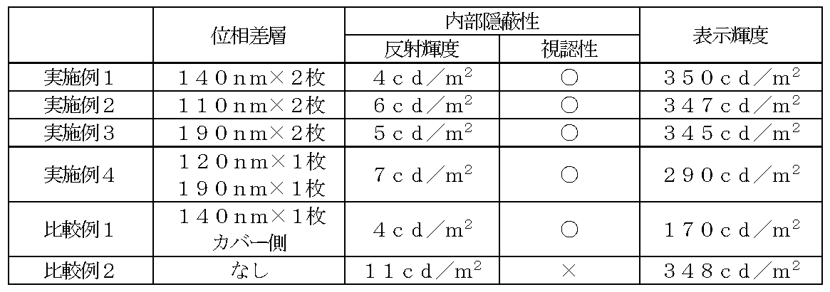
表1から明らかなように、実施例のヘッドアップディスプレイ装置は、内部隠蔽性と表示輝度とを同時に満足することがわかる。
本発明の実施形態によるヘッドアップディスプレイ装置は、フロントガラスを備える車両(代表的には、自動車)に好適に用いられ得る。
10 表示器
11 表示セル
12 第1の位相差層付偏光板
20 反射器
30 筐体
40 カバー部材
50 第2の位相差層付偏光板
100 ヘッドアップディスプレイ装置
101 ヘッドアップディスプレイ装置
11 表示セル
12 第1の位相差層付偏光板
20 反射器
30 筐体
40 カバー部材
50 第2の位相差層付偏光板
100 ヘッドアップディスプレイ装置
101 ヘッドアップディスプレイ装置
Claims (4)
- 表示セルと、該表示セルの出射側において該表示セル側から順に偏光子および第1の位相差層を含む第1の位相差層付偏光板と、を含み、投影光を出射する表示器と;
該投影光を反射する少なくとも1つの反射器と;
開口部を有し、かつ、該表示器および該反射器を内部に収容する筐体と;
該開口部を覆うカバー部材と;
該カバー部材の筐体内部側に設けられた、該カバー部材側から順に偏光子と第2の位相差層とを含む第2の位相差層付偏光板と;を有し、
該第1の位相差層および該第2の位相差層の面内位相差Re(550)が、それぞれ100nm~200nmである、
ヘッドアップディスプレイ装置。 - 前記偏光子が、下記式(1)で表される芳香族ジスアゾ化合物を含む、請求項1に記載のヘッドアップディスプレイ装置:

- 前記偏光子の厚みが100nm~1000nmである、請求項1または2に記載のヘッドアップディスプレイ装置。
- 前記開口部を介して前記筐体から出射した投影光のフロントガラスに対する反射角が10°~50°となるよう構成されている、請求項1から3のいずれかに記載のヘッドアップディスプレイ装置。
Priority Applications (4)
| Application Number | Priority Date | Filing Date | Title |
|---|---|---|---|
| KR1020207010426A KR20200085735A (ko) | 2017-11-09 | 2018-10-16 | 헤드업 디스플레이 장치 |
| CN201880067760.0A CN111226159B (zh) | 2017-11-09 | 2018-10-16 | 抬头显示器装置 |
| US16/756,957 US11567315B2 (en) | 2017-11-09 | 2018-10-16 | Head-up display device |
| EP18876797.4A EP3709070A4 (en) | 2017-11-09 | 2018-10-16 | HEAD-UP DISPLAY DEVICE |
Applications Claiming Priority (4)
| Application Number | Priority Date | Filing Date | Title |
|---|---|---|---|
| JP2017216115 | 2017-11-09 | ||
| JP2017-216115 | 2017-11-09 | ||
| JP2018194391A JP2019086766A (ja) | 2017-11-09 | 2018-10-15 | ヘッドアップディスプレイ装置 |
| JP2018-194391 | 2018-10-15 |
Publications (1)
| Publication Number | Publication Date |
|---|---|
| WO2019093079A1 true WO2019093079A1 (ja) | 2019-05-16 |
Family
ID=66437847
Family Applications (1)
| Application Number | Title | Priority Date | Filing Date |
|---|---|---|---|
| PCT/JP2018/038450 WO2019093079A1 (ja) | 2017-11-09 | 2018-10-16 | ヘッドアップディスプレイ装置 |
Country Status (1)
| Country | Link |
|---|---|
| WO (1) | WO2019093079A1 (ja) |
Citations (33)
| Publication number | Priority date | Publication date | Assignee | Title |
|---|---|---|---|---|
| JPS5083482A (ja) | 1973-11-26 | 1975-07-05 | ||
| JPS62225429A (ja) * | 1986-03-28 | 1987-10-03 | Yazaki Corp | 車載用ヘツドアツプデイスプレイ装置 |
| JPH01240517A (ja) | 1988-03-22 | 1989-09-26 | Japan Synthetic Rubber Co Ltd | 重合体並びにその前駆体および製造方法 |
| JPH02113920A (ja) | 1988-10-25 | 1990-04-26 | Mitsubishi Kasei Corp | 延伸フィルム又はシートの製造方法 |
| JPH0314882A (ja) | 1989-03-10 | 1991-01-23 | Mitsui Petrochem Ind Ltd | メッキ用組成物およびメッキ物 |
| JPH03122137A (ja) | 1989-10-06 | 1991-05-24 | Japan Synthetic Rubber Co Ltd | 熱可塑性樹脂成形品 |
| JPH03182701A (ja) | 1989-12-13 | 1991-08-08 | Nippon Kayaku Co Ltd | 延伸フィルム及びその製造法 |
| JPH06885U (ja) * | 1992-06-05 | 1994-01-11 | 日本精機株式会社 | 車両用表示装置 |
| JP2000009912A (ja) | 1998-06-25 | 2000-01-14 | Nitto Denko Corp | 延伸フィルムの製造方法及び位相差板 |
| JP2000230016A (ja) | 1998-12-09 | 2000-08-22 | Nippon Shokubai Co Ltd | 透明性耐熱樹脂の製造方法とその用途 |
| WO2001037007A1 (fr) | 1999-11-12 | 2001-05-25 | Kaneka Corporation | Film transparent |
| JP2001151814A (ja) | 1999-11-26 | 2001-06-05 | Nippon Shokubai Co Ltd | 透明性耐熱樹脂の製造方法およびその用途 |
| JP2001343529A (ja) | 2000-03-30 | 2001-12-14 | Kanegafuchi Chem Ind Co Ltd | 偏光子保護フィルムおよびその製造方法 |
| JP2002022944A (ja) | 2000-07-06 | 2002-01-23 | Fuji Photo Film Co Ltd | 円偏光板およびその製造方法 |
| JP2002086554A (ja) | 2000-07-10 | 2002-03-26 | Fuji Photo Film Co Ltd | ポリマーフィルムの延伸方法、偏光膜、偏光板および位相差膜の製造方法、および液晶表示装置 |
| JP2002120326A (ja) | 2000-10-18 | 2002-04-23 | Nippon Shokubai Co Ltd | 透明熱可塑性樹脂積層体 |
| JP2002254544A (ja) | 2001-03-05 | 2002-09-11 | Nippon Shokubai Co Ltd | 熱可塑性樹脂積層体 |
| JP2004070296A (ja) | 2002-06-14 | 2004-03-04 | Toray Ind Inc | 偏光板保護シートおよび偏光板 |
| JP2005146084A (ja) | 2003-11-13 | 2005-06-09 | Nippon Shokubai Co Ltd | ラクトン環含有重合体とその製造方法ならびに用途 |
| JP2007171943A (ja) | 2005-11-28 | 2007-07-05 | Nitto Denko Corp | 光学補償層付偏光板およびそれを用いた画像表示装置 |
| JP2008070504A (ja) | 2006-09-13 | 2008-03-27 | Nippon Seiki Co Ltd | 表示装置 |
| JP2010152005A (ja) * | 2008-12-24 | 2010-07-08 | Nippon Sheet Glass Co Ltd | ヘッドアップディスプレイ |
| JP2012073580A (ja) | 2010-09-03 | 2012-04-12 | Nitto Denko Corp | 薄型偏光膜の製造方法 |
| JP2012194357A (ja) * | 2011-03-16 | 2012-10-11 | Nitto Denko Corp | 偏光フィルム、コーティング液、及び画像表示装置 |
| US20130279016A1 (en) * | 2010-12-23 | 2013-10-24 | Eckhard Finger | Head-up display for a motor vehicle |
| JP2014010291A (ja) | 2012-06-29 | 2014-01-20 | Nitto Denko Corp | 円偏光板および表示装置 |
| JP2014026266A (ja) | 2012-06-21 | 2014-02-06 | Nitto Denko Corp | 偏光板および有機elパネル |
| JP2015005272A (ja) | 2013-05-22 | 2015-01-08 | 日東電工株式会社 | 両面透明導電性フィルムおよびタッチパネル |
| JP2015115171A (ja) | 2013-12-11 | 2015-06-22 | 日東電工株式会社 | 透明導電性フィルム及びその用途 |
| JP2015120870A (ja) | 2013-11-20 | 2015-07-02 | Dicグラフィックス株式会社 | 印刷インキ組成物 |
| JP2015141674A (ja) | 2014-01-30 | 2015-08-03 | 日東電工株式会社 | 両面透明導電性フィルム及びその巻回体、並びにタッチパネル |
| JP2015222337A (ja) * | 2014-05-23 | 2015-12-10 | 日本精機株式会社 | 表示装置 |
| WO2017094248A1 (ja) * | 2015-12-01 | 2017-06-08 | パナソニックIpマネジメント株式会社 | 自由曲面レンズ、および、ヘッドアップディスプレイ |
-
2018
- 2018-10-16 WO PCT/JP2018/038450 patent/WO2019093079A1/ja unknown
Patent Citations (33)
| Publication number | Priority date | Publication date | Assignee | Title |
|---|---|---|---|---|
| JPS5083482A (ja) | 1973-11-26 | 1975-07-05 | ||
| JPS62225429A (ja) * | 1986-03-28 | 1987-10-03 | Yazaki Corp | 車載用ヘツドアツプデイスプレイ装置 |
| JPH01240517A (ja) | 1988-03-22 | 1989-09-26 | Japan Synthetic Rubber Co Ltd | 重合体並びにその前駆体および製造方法 |
| JPH02113920A (ja) | 1988-10-25 | 1990-04-26 | Mitsubishi Kasei Corp | 延伸フィルム又はシートの製造方法 |
| JPH0314882A (ja) | 1989-03-10 | 1991-01-23 | Mitsui Petrochem Ind Ltd | メッキ用組成物およびメッキ物 |
| JPH03122137A (ja) | 1989-10-06 | 1991-05-24 | Japan Synthetic Rubber Co Ltd | 熱可塑性樹脂成形品 |
| JPH03182701A (ja) | 1989-12-13 | 1991-08-08 | Nippon Kayaku Co Ltd | 延伸フィルム及びその製造法 |
| JPH06885U (ja) * | 1992-06-05 | 1994-01-11 | 日本精機株式会社 | 車両用表示装置 |
| JP2000009912A (ja) | 1998-06-25 | 2000-01-14 | Nitto Denko Corp | 延伸フィルムの製造方法及び位相差板 |
| JP2000230016A (ja) | 1998-12-09 | 2000-08-22 | Nippon Shokubai Co Ltd | 透明性耐熱樹脂の製造方法とその用途 |
| WO2001037007A1 (fr) | 1999-11-12 | 2001-05-25 | Kaneka Corporation | Film transparent |
| JP2001151814A (ja) | 1999-11-26 | 2001-06-05 | Nippon Shokubai Co Ltd | 透明性耐熱樹脂の製造方法およびその用途 |
| JP2001343529A (ja) | 2000-03-30 | 2001-12-14 | Kanegafuchi Chem Ind Co Ltd | 偏光子保護フィルムおよびその製造方法 |
| JP2002022944A (ja) | 2000-07-06 | 2002-01-23 | Fuji Photo Film Co Ltd | 円偏光板およびその製造方法 |
| JP2002086554A (ja) | 2000-07-10 | 2002-03-26 | Fuji Photo Film Co Ltd | ポリマーフィルムの延伸方法、偏光膜、偏光板および位相差膜の製造方法、および液晶表示装置 |
| JP2002120326A (ja) | 2000-10-18 | 2002-04-23 | Nippon Shokubai Co Ltd | 透明熱可塑性樹脂積層体 |
| JP2002254544A (ja) | 2001-03-05 | 2002-09-11 | Nippon Shokubai Co Ltd | 熱可塑性樹脂積層体 |
| JP2004070296A (ja) | 2002-06-14 | 2004-03-04 | Toray Ind Inc | 偏光板保護シートおよび偏光板 |
| JP2005146084A (ja) | 2003-11-13 | 2005-06-09 | Nippon Shokubai Co Ltd | ラクトン環含有重合体とその製造方法ならびに用途 |
| JP2007171943A (ja) | 2005-11-28 | 2007-07-05 | Nitto Denko Corp | 光学補償層付偏光板およびそれを用いた画像表示装置 |
| JP2008070504A (ja) | 2006-09-13 | 2008-03-27 | Nippon Seiki Co Ltd | 表示装置 |
| JP2010152005A (ja) * | 2008-12-24 | 2010-07-08 | Nippon Sheet Glass Co Ltd | ヘッドアップディスプレイ |
| JP2012073580A (ja) | 2010-09-03 | 2012-04-12 | Nitto Denko Corp | 薄型偏光膜の製造方法 |
| US20130279016A1 (en) * | 2010-12-23 | 2013-10-24 | Eckhard Finger | Head-up display for a motor vehicle |
| JP2012194357A (ja) * | 2011-03-16 | 2012-10-11 | Nitto Denko Corp | 偏光フィルム、コーティング液、及び画像表示装置 |
| JP2014026266A (ja) | 2012-06-21 | 2014-02-06 | Nitto Denko Corp | 偏光板および有機elパネル |
| JP2014010291A (ja) | 2012-06-29 | 2014-01-20 | Nitto Denko Corp | 円偏光板および表示装置 |
| JP2015005272A (ja) | 2013-05-22 | 2015-01-08 | 日東電工株式会社 | 両面透明導電性フィルムおよびタッチパネル |
| JP2015120870A (ja) | 2013-11-20 | 2015-07-02 | Dicグラフィックス株式会社 | 印刷インキ組成物 |
| JP2015115171A (ja) | 2013-12-11 | 2015-06-22 | 日東電工株式会社 | 透明導電性フィルム及びその用途 |
| JP2015141674A (ja) | 2014-01-30 | 2015-08-03 | 日東電工株式会社 | 両面透明導電性フィルム及びその巻回体、並びにタッチパネル |
| JP2015222337A (ja) * | 2014-05-23 | 2015-12-10 | 日本精機株式会社 | 表示装置 |
| WO2017094248A1 (ja) * | 2015-12-01 | 2017-06-08 | パナソニックIpマネジメント株式会社 | 自由曲面レンズ、および、ヘッドアップディスプレイ |
Non-Patent Citations (2)
| Title |
|---|
| See also references of EP3709070A4 * |
| YUTAKA HOSODA: "Theoretical Production Dye Chemistry Fifth Edition", 15 July 1968, GIHODO, pages: 135 - 152 |
Similar Documents
| Publication | Publication Date | Title |
|---|---|---|
| JP7309264B2 (ja) | ヘッドアップディスプレイ装置 | |
| WO2020152949A1 (ja) | ヘッドアップディスプレイ装置およびその製造方法 | |
| US11933979B2 (en) | Head-up display device | |
| JP2023059916A (ja) | ヘッドアップディスプレイ装置およびその製造方法 | |
| JP7253893B2 (ja) | ヘッドアップディスプレイ装置 | |
| JP2019086766A (ja) | ヘッドアップディスプレイ装置 | |
| US11650419B2 (en) | Head-up display apparatus | |
| WO2019093079A1 (ja) | ヘッドアップディスプレイ装置 | |
| US11215821B2 (en) | Head-up display device | |
| US11966050B2 (en) | Head-up display apparatus | |
| WO2019078190A1 (ja) | ヘッドアップディスプレイ装置 | |
| WO2019078192A1 (ja) | ヘッドアップディスプレイ装置 |
Legal Events
| Date | Code | Title | Description |
|---|---|---|---|
| 121 | Ep: the epo has been informed by wipo that ep was designated in this application |
Ref document number: 18876797 Country of ref document: EP Kind code of ref document: A1 |
|
| NENP | Non-entry into the national phase |
Ref country code: DE |
|
| ENP | Entry into the national phase |
Ref document number: 2018876797 Country of ref document: EP Effective date: 20200609 |