WO2019065101A1 - 空気流搬送装置 - Google Patents
空気流搬送装置 Download PDFInfo
- Publication number
- WO2019065101A1 WO2019065101A1 PCT/JP2018/032578 JP2018032578W WO2019065101A1 WO 2019065101 A1 WO2019065101 A1 WO 2019065101A1 JP 2018032578 W JP2018032578 W JP 2018032578W WO 2019065101 A1 WO2019065101 A1 WO 2019065101A1
- Authority
- WO
- WIPO (PCT)
- Prior art keywords
- air flow
- transport
- wall
- transfer
- path
- Prior art date
- Legal status (The legal status is an assumption and is not a legal conclusion. Google has not performed a legal analysis and makes no representation as to the accuracy of the status listed.)
- Ceased
Links
Images






Classifications
-
- A—HUMAN NECESSITIES
- A63—SPORTS; GAMES; AMUSEMENTS
- A63F—CARD, BOARD, OR ROULETTE GAMES; INDOOR GAMES USING SMALL MOVING PLAYING BODIES; VIDEO GAMES; GAMES NOT OTHERWISE PROVIDED FOR
- A63F7/00—Indoor games using small moving playing bodies, e.g. balls, discs or blocks
- A63F7/02—Indoor games using small moving playing bodies, e.g. balls, discs or blocks using falling playing bodies or playing bodies running on an inclined surface, e.g. pinball games
-
- B—PERFORMING OPERATIONS; TRANSPORTING
- B65—CONVEYING; PACKING; STORING; HANDLING THIN OR FILAMENTARY MATERIAL
- B65G—TRANSPORT OR STORAGE DEVICES, e.g. CONVEYORS FOR LOADING OR TIPPING, SHOP CONVEYOR SYSTEMS OR PNEUMATIC TUBE CONVEYORS
- B65G51/00—Conveying articles through pipes or tubes by fluid flow or pressure; Conveying articles over a flat surface, e.g. the base of a trough, by jets located in the surface
- B65G51/02—Directly conveying the articles, e.g. slips, sheets, stockings, containers or workpieces, by flowing gases
- B65G51/03—Directly conveying the articles, e.g. slips, sheets, stockings, containers or workpieces, by flowing gases over a flat surface or in troughs
-
- B—PERFORMING OPERATIONS; TRANSPORTING
- B65—CONVEYING; PACKING; STORING; HANDLING THIN OR FILAMENTARY MATERIAL
- B65H—HANDLING THIN OR FILAMENTARY MATERIAL, e.g. SHEETS, WEBS, CABLES
- B65H29/00—Delivering or advancing articles from machines; Advancing articles to or into piles
- B65H29/24—Delivering or advancing articles from machines; Advancing articles to or into piles by air blast or suction apparatus
-
- B—PERFORMING OPERATIONS; TRANSPORTING
- B65—CONVEYING; PACKING; STORING; HANDLING THIN OR FILAMENTARY MATERIAL
- B65H—HANDLING THIN OR FILAMENTARY MATERIAL, e.g. SHEETS, WEBS, CABLES
- B65H5/00—Feeding articles separated from piles; Feeding articles to machines
- B65H5/22—Feeding articles separated from piles; Feeding articles to machines by air-blast or suction device
-
- G—PHYSICS
- G07—CHECKING-DEVICES
- G07D—HANDLING OF COINS OR VALUABLE PAPERS, e.g. TESTING, SORTING BY DENOMINATIONS, COUNTING, DISPENSING, CHANGING OR DEPOSITING
- G07D9/00—Counting coins; Handling of coins not provided for in the other groups of this subclass
Definitions
- the present invention relates to an air flow transfer device for transferring a sheet-like or thin plate-like object by an air flow.
- a transport device including a transport belt that transports while contacting a banknote, and a transport mechanism such as a drive roller that drives the transport belt is used.
- a transport belt that transports while contacting a banknote
- a transport mechanism such as a drive roller that drives the transport belt
- Patent Document 1 a conveyance device which generates an air flow for conveyance in a hollow conveyance pipe, and conveys a bill by placing the air flow on the air flow.
- Patent Document 2 a conveyance device which generates an air flow for conveyance in a hollow conveyance pipe, and conveys a bill by placing the air flow on the air flow.
- FIG. 13 is a schematic view of a transfer pipe according to a conventional example
- FIG. 13 (a) is a perspective view
- FIG. 13 (b) is a cross-sectional view taken along line CC of FIG. 13 (a).
- the transport pipe 200 has a quadrangular prism-shaped transport path 205 formed by four smooth inner wall surfaces 201.
- the transport pipe 200 generates an air flow 210 flowing in the transport path 205 from one side to the other in the longitudinal direction, and inserts the bill 220 into the transport pipe 200 from one side in the longitudinal direction.
- the bill 220 is in a posture extending substantially along the transport path 205, the following problems occur in the transport of the bill 220.
- the first problem is that the bill 220 is adsorbed to the inner wall surface 201 of the transport pipe 200 facing the main surface 221 of the bill 220, and the bill 220 can not be transported. This is because, when the bill 220 is biased to the inner wall surface 201 of the transport pipe 200, the flow velocity of the air flow on the biased side is increased, and a negative pressure is generated between the bill 220 and the inner wall surface 201, and the bill 220 is It is considered to be due to being drawn to the wall surface 201.
- the second problem is that when the air flow 210 flowing in the transport pipe 200 is accelerated, turbulence is generated and the bill 220 can not be transported. When the velocity of the air flow 210 flowing in the transfer pipe 200 is relatively low, the air flow 210 flowing in the transfer pipe 200 maintains a laminar flow that moves regularly along the longitudinal direction of the transfer pipe 200.
- Turbulent flow is a state of flow in which the air flow randomly moves in the transfer pipe 200.
- the banknote 220 flaps in the transport pipe 200, and eventually, the banknote 220 is attracted to the inner wall surface 201 and is not transported for contact, or transport failure occurs.
- the back end of the bill in order to convey a bill by air flow using a conveyance pipe, the back end of the bill is bent and deformed in a J shape, and the wind pressure of the air flow for conveyance is applied to the curved deformation portion.
- conveyance of a banknote is implement
- Patent No. 4130697 Patent No. 5563883 gazette
- Patent Document 2 since the paper sheet is forcibly pushed out using the pushing unit, when the paper sheet is strongly adsorbed to the inner wall surface, the paper sheet is compressed and deformed, which causes a jam in the conveyance pipe. And there is a problem that fatal damage is applied to the paper.
- the push-in unit system is susceptible to the air volume, and is not suitable for conveying the curved portion or long distance conveyance. Further, in the prior art in which paper sheets are conveyed in the horizontal direction using an air flow, the paper is limited to conveyance in a posture in which the width direction of the paper sheets is the gravity direction. could not be transported.
- the present invention has been made in view of the above-mentioned circumstances, and an auxiliary member for conveyance is unnecessary, and the conveyance object is stabilized by the air flow while preventing the deformation of the conveyance object such as paper sheets and the like. It is an object of the present invention to provide a novel airflow conveying device which can carry and convey a transported object by setting the angle of the main surface of the transported object to a free angle with respect to the gravity direction.
- the airflow carrier device of the present invention forms a conveyance way which conveys a sheet-like or thin plate-like conveyance thing by airflow, and the said conveyance way conveyed along the conveyance way
- a transfer pipe having two main inner walls respectively parallel to both main surfaces of the object, an air flow generating device for generating a main transfer air flow from one of the transfer paths toward the other in the transfer path, each main inner wall, An opposing member disposed opposite to each other with a predetermined gap therebetween, and having opposing surfaces respectively opposing the main surfaces of the transported object to be conveyed, and forming the conveying path between the opposing surfaces;
- a plurality of wall flow generation units each formed on the respective opposing members to generate a wall flow that prevents the transported object being conveyed from contacting or adsorbing on the opposing surfaces.
- the air flow transfer device of the present invention forms a transfer path for transferring a sheet-like or thin plate-like transferred object by an air flow, and the above-mentioned transfer is performed along the transfer path.
- a transfer pipe having two main inner walls respectively facing both main surfaces of the transferred object, an air flow generating device for generating a main transfer air flow from one side of the transfer path to the other in the transfer path, and each main And a plurality of wall flow generating parts each comprising a recess for forming a wall flow which is formed on the inner wall to prevent the transported object being conveyed from contacting or adsorbing to the main inner wall.
- the auxiliary member for conveyance is unnecessary, and the conveyance object can be stably conveyed by the air flow while preventing the deformation of the conveyance object such as a paper sheet.
- FIG. 1 is a cross-sectional view
- FIG. 2 is BB sectional drawing of (a)
- FIG. 3 shows the conveyance pipe which concerns on 1st embodiment of this invention, (a) is a cross-sectional view, (b) is BB sectional drawing of (a), (c) is (a) ) Of FIG.
- FIG. 1 It is a figure which shows the detail of a wall flow generation
- (a) is a partial expansion perspective view
- (b) is the EE sectional drawing of (a).
- (A) to (c) are a plan view and a partially enlarged longitudinal sectional view of an opposing surface for explaining an example of a wall flow generation unit according to a third embodiment of the present invention. It is a cross-sectional view which shows the conveyance pipe which concerns on the modification of 3rd embodiment of this invention. It is a longitudinal cross-sectional view which shows the curved part of the conveyance pipe
- FIGS. 1 (a) and 1 (b) schematically illustrate the transport path of the transport pipe in order to explain in principle the configuration of the transport path of the transport pipe provided in the preferred embodiment of the airflow transport device of the present invention.
- FIG. 1 is a conceptual view shown, and FIG. 1 is a cross-sectional view corresponding to a cross-section taken along the line CC of FIG.
- the transfer pipe 100 shown in FIG. 1 has a transfer path 110 inside.
- a main transport air stream 10 (10 a, 10 b) for transporting the transported object S is formed in the transport path 110 of the transport pipe 100.
- the main transport air stream 10 flows from one side (left side in the figure) of the transport path 110 in the longitudinal direction to the other side (right side in the figure).
- the embodiment of the present invention is characterized in that the wall flow 11 (11a, 11b) is generated in the conveyance path 110 as an air flow different from the main conveyance air stream 10.
- the wall flows 11 (11a, 11b) are, as shown in FIG. 1A, both main surfaces S1, S1 of the transported object S transported in the regular transport posture, and both main surfaces S1, S1 thereof.
- the opposing surface 121 (121a, 121b) of the conveyance path 110 which each opposes, respectively.
- the wall flow 11 (11a, 11b) is an air flow that acts to prevent the transported object S being transported from approaching, coming into contact with, or adsorbing to the facing surface 121.
- This wall flow 11 (11a, 11b) is generated on the opposing surface 121 even if it is an air flow blown toward the transported object S, like a cushion between the transported object S and the opposing surface 121. It may be a fine vortex that functions.
- the wall flow generation unit generates a wall flow 11 (11a, 11b) according to the state of the main carrier air stream 10 sent into the carrier path 110, which will be described later with reference to FIG.
- the wall flow 11 (11a, 11b) can also be referred to as a transfer auxiliary flow that assists the transfer of the object S with respect to the main transfer air stream 10 (10a, 10b) sent into the transfer path 110.
- the conveyed object S conveyed by the conveying pipe 100 of the air flow conveying device shown in FIG. 1 is, for example, a sheet or thin plate such as a paper sheet, a card, a bill bundle etc.
- the material of the object S is not particularly limited.
- the to-be-conveyed object S passes at a substantially central position in the conveyance pipe 100. It means that the object S can be transported along the transport direction so that the transported object S does not have compressive deformation without approaching, contacting or adsorbing the opposing surface 121 of the transport path 110.
- Reynolds number is known as a value that characterizes the behavior of fluid such as air.
- the upper critical Reynolds number which is the Reynolds number when the fluid transitions from laminar flow to turbulent flow, is defined as follows.
- Re Ud / v .. Formula (1)
- U the flow velocity of the air flow [m / s]
- d the representative length of the cross section in the air flow pipe [m]
- v the dynamic viscosity of the fluid [m ⁇ 2 / s].
- ⁇ viscosity coefficient of fluid [kg / ms]
- q density of fluid [kg / m ⁇ 3].
- the viscosity coefficient ⁇ can be reduced as much as possible, the upper critical Reynolds number Re can be increased as much as possible. That is, since the upper critical Reynolds number at which transition from laminar flow to turbulent flow can be increased, laminar flow can be maintained even if the air flow velocity U is increased.
- the wall flow 11 (11a, 11b) is generated in the conveyance path 110 as an air flow different from the main conveyance airflow 10 (10a, 10b).
- the following effects occur.
- Second, the reduction of the viscous drag can lower the dynamic viscosity coefficient v and improve the upper critical Reynolds number. That is, even if the flow velocity U of the main transport air stream 10 is increased, the laminar flow can be maintained, and flapping during transport of the object S can be prevented.
- the wall flow 11 can push back the transferred object S approaching the facing surface 121 toward the central portion of the transfer path 110 to prevent the transferred object S from being adsorbed to the facing surface 121. The third effect is described.
- Fig.1 (a) when the to-be-conveyed object S is conveyed by center part vicinity of the thickness direction (direction orthogonal to the longitudinal direction which is the conveyance direction) of the conveyance path 110, the to-be-conveyed object S
- the flow velocity and air pressure of the main carrier air stream 10 (10a, 10b) flowing between the and each opposing surface 121a, 121b are substantially equal, and the wall flow 11 (11a, 11b) generated in the respective opposing surface 121a, 121b
- the flow of the main transportation air stream 10a is It becomes faster than the flow of the main carrier air stream 10b. Since a wall flow 11a of a size corresponding to the state of the main transport air stream 10 is generated on the opposing surface 121a, the main transport having high speed is performed between the opposing surface 121a and the main surface S1 of the transported object S. A strong wall flow 11a is generated according to the air flow 10a. The to-be-conveyed object S is pushed back toward the central part of the conveyance path 110 by this strong wall flow 11a, as shown to Fig.1 (a). As a result, the to-be-conveyed object S is smoothly conveyed in the conveyance path 110 without being adsorbed to the facing surface 121 a.
- the airflow transport device 1 is a device that transports a to-be-conveyed object S such as a bill or a card by an airflow.
- the air flow transfer device 1 according to the present embodiment generates a wall flow on the opposite surface of the transfer pipe 100 by forming the wall flow on the opposite surface of the transfer path 110, and generates the wall flow on the opposite surface of the transported object S.
- the present embodiment is characterized in that the main transport air stream 10 for transporting the transported object S is maintained in a laminar flow so that the transported object S can be transported stably along the transport direction while preventing adsorption.
- the transport direction is along the longitudinal direction of the transport path 110 of the transport pipe 100.
- the object S to be transported by the airflow transport device 1 is a sheet-like member (e.g., a paper sheet such as a bill or a securities), a thin plate-like member (e.g., a card), These bundles etc. are included.
- the material of the conveyed object S may be paper, plastic, metal foil, or any other material.
- the main surface of the transferred object S is a wide surface other than the end surface extending in the thickness direction of the transferred object S (direction orthogonal to the longitudinal direction which is the transfer direction).
- the transported object S is transported while maintaining a substantially elongated posture along the transport direction (longitudinal direction) at the time of transport.
- the gas for transferring the transferred object S is preferably air, but other than air. The following gases and fluids may be used.
- the direction along the transport direction of the transported object S is the longitudinal direction
- the direction along the width direction of the transported object S is the width direction and a direction orthogonal to both the longitudinal direction and the width direction Will be described as the thickness direction.
- FIG. 2 is a schematic view showing the overall configuration of the airflow transfer device 1 according to an embodiment of the present invention.
- the airflow transport device 1 is configured to transport a transport path 110 that transports the transported object S by the airflow, and travels from one side to the other in the longitudinal direction of the transport path 110 (transport direction And an air flow generating device 20 for generating a main transfer air flow 10 which is an air flow in the transfer path 110.
- the airflow transfer device 1 is disposed at an intermediate position in the longitudinal direction of the transfer pipe 100, and the plurality of charging ports 30 for introducing the object S into the transfer path 110; And a recovery device 40 for recovering the transported object S disposed at the other end and transported.
- the collection device 40 in the case where the transported object S is a bill is, for example, a safe that stores the bill.
- the air flow generating device 20 is disposed at one end in the longitudinal direction of the transport pipe 100 (upstream end in the transport direction).
- the air flow generating device 20 blows air into the conveyance path 110 to generate a main conveyance air flow 10 directed from one side to the other in the longitudinal direction of the conveyance path 110.
- the main carrier air flow 10 which is an air flow generated by the air flow generator 20 can flow evenly in the carrier path 110 as a laminar flow.
- the airflow generation device 20 is disposed at the other end (downstream end in the transport direction) of the transport pipe 100 in the longitudinal direction as described above. It may be a device that generates the main carrier air flow 10 by sucking air and exhausting it to the outside.
- the air flow generating device 20 is disposed at an intermediate portion in the longitudinal direction of the transfer pipe 100, and generates the main transfer air flow 10 by suctioning air from the transfer path 110 or by flowing air into the transfer path 110. It may be a device that Furthermore, a plurality of airflow generating devices 20 may be provided in the airflow conveying device 1.
- FIG. 2 shows the airflow transfer device 1 including the transfer pipe 100 having the straight transfer path 110 as an example, the transfer path 110 of the transfer pipe 100 may be curved or bent, and the air flow
- the transport apparatus 1 may include an annular transport path 110 that circulates the main transport airflow generated by the airflow generation device 20.
- the airflow transfer device 1 may include a transfer path 110 having a branch.
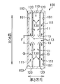
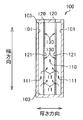
- FIG. Fig. 3 is a view showing the transfer pipe 100 according to the first embodiment of the present invention
- Fig. 3 (a) is a cross-sectional view
- Fig. 3 (b) is a BB of Fig. 3 (a)
- FIG. 3 (c) is a cross-sectional view taken along the line CC of FIG. 3 (a).
- FIG. 3A is a cross-sectional view cut along a plane orthogonal to the transport direction of the article S, and is a view corresponding to the AA cross section of FIG.
- the conveyance pipe 100 shown in FIG. 3 includes a plurality of opposed plates (opposite members) 120 and a plurality of wall flow generation units 130, as particularly shown in FIGS. 3 (a) and 3 (c).
- Each opposing plate (opposing member) 120 has opposing surfaces 121 and 121 that respectively oppose the main surfaces S1 and S1 of the article S.
- the wall flow generation unit 130 is formed on the opposing plate 120, and the wall flow generation unit 130 generates a wall flow 11 that prevents adsorption of the transported object S on the opposing plate 120 during transport.
- the transfer pipe 100 is a duct having a hollow space whose cross-sectional shape is substantially rectangular.
- the conveying pipe 100 extends along the longitudinal direction (conveying direction) shown in FIGS. 3A and 3C and includes the first inner walls 101 and 101 of the conveying pipe 100 facing each other, and FIG. And second inner walls 103, 103 shown in FIG. 3 (b).
- the first inner wall 101, 101 of the transfer pipe 100 is a relatively wide surface extending in the direction along the main surfaces S1, S1 of the transported object S to be transferred, and the second inner wall 103, 103 of the transfer pipe 100 is transfer It is a relatively narrow surface substantially orthogonal to the first inner walls 101, 101 of the tube 100.
- a pair of opposing plates 120, 120 extending along the transport direction is disposed in parallel along the transport direction in the transport pipe 100.
- a transport path 110 is formed between the facing plates 120 and 120.
- the opposing plates 120, 120 are spaced apart from the first inner wall 101, 101 of the transport pipe 100 by a predetermined distance, First air flow paths 111 and 111 are formed between 120 and 120 and the first inner walls 101 and 101 of the transfer pipe 100. Further, as shown in FIGS.
- the opposing plates 120 and 120 are disposed apart from the second inner walls 103 and 103 by providing a predetermined distance.
- second air flow paths 113, 113 are formed in the region between the opposing plates 120, 120 and the second inner walls 103, 103.
- the first air flow paths 111, 111 are disposed in parallel with the transport path 110 with the opposing plates 120, 120 interposed therebetween.
- the opposing plates 120 and 120 are supported by stays (not shown) as a plurality of fixing members attached to, for example, the first inner wall 101 and 101 or the second inner walls 103 and 103 of the transfer pipe 100.
- the stay is preferably disposed at a predetermined interval along the longitudinal direction of the transfer pipe 100, and supports the opposing plate 120 at a position where the various air flows in the transfer pipe 100 are not obstructed.
- the opposing plates 120 and 120 are spaced apart from, for example, the first inner wall 101 or 101 or the second inner wall 103 or 103 of the transport pipe 100, for example, using studs or collars as fixing members. It may be fixed.
- the width between the opposing plates 120 can be set preferably in the range of about 9 mm to 16 mm, and more preferably in the range of 10 mm to 13 mm.
- the gap between the opposing plates is less than 9 mm, when a bill with a fold or a bend is inserted into the transport pipe, the phenomenon of contact between the opposing plates 120 occurs and frictional resistance occurs to stably convey It is not preferable because it can not be done.
- the distance between the opposing plates exceeds 16 mm, the volume of the transfer pipe 100 increases, and the output of the air flow generating device 20 needs to be increased, which is not preferable.
- the plurality of wall flow generation units 130 are arranged on the facing surface 121 preferably in a staggered manner, for example, in a state of being alternately arranged. .
- the wall flow 11 generated by each wall flow generation unit 130 is a wall flow positioned forward and backward with respect to the transport direction It is hard to receive the influence by the wall flow 11 which the generation part 130 generates. For this reason, since each wall flow generation part 130 can form the stable wall flow 11 in the conveyance path 110, the to-be-conveyed object S can be conveyed in the conveyance path 110 more stably.
- line which consists of several wall flow generation part 130 adjacently arranged by the width direction with the zigzag form comprises the other wall flow generation part row located in a longitudinal direction front-back direction It refers to a state in which the position in the width direction is shifted between the individual wall flow generating portions.
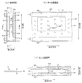
- FIG. 4 is a view showing details of the wall flow generation unit 130
- FIG. 4 (a) is a partially enlarged perspective view of the wall flow generation unit 130
- FIG. 4 (b) is an E-- of FIG. It is E sectional drawing.
- a plurality of wall flow generation parts 130 are formed in the opposing plate 120.
- the plurality of wall flow generation units 130 generate wall flows 11 as illustrated in FIGS. 4A and 4B in order to prevent adsorption of the transported object S to the facing surface 121 during conveyance. Structure.
- the wall flow generation unit 130 includes a through hole 131 and a guide member 133.
- the through holes 131 are formed through the opposing plate 120.
- the guide member 133 is formed corresponding to the through hole 131.
- the guide member 133 is formed so as to extend (project) from the peripheral edge 131 b excluding the upstream end edge 131 a of the through hole 131 to the first air flow passage 111 side.
- the guide member 133 is a guide member for introducing air for spouting the air flow in the first air flow passage 111 to the transport path 110 via the through hole 131. As shown in FIGS.
- the guide member 133 has a curved guide surface 133a on the side of the guide member 133 facing the conveyance path 110.
- the guide surface 133 a jets the air flow introduced from the first air flow passage 111 side toward the transfer passage 110 as the wall flow 11 in an oblique direction toward the transfer passage 110.
- the through holes 131 preferably have a shape in which the width thereof gradually decreases toward the downstream side in the transport direction.
- the air flow introduced from the first air flow passage 111 can be jetted as the wall flow 11 toward the transport path 110 while being guided by the curved guide surface 133a.
- the guide member 133 has a shape in which the amount of protrusion toward the first air flow passage 111 gradually increases toward the upstream side in the transport direction.
- the air flow introduced from the first air flow passage 111 can be reliably ejected as the wall flow 11 toward the transport path 110 while being guided by the curved guide surface 133a.
- the inclination angle ⁇ shown in FIG. 4B is an angle indicating that the central portion in the width direction of the guide surface 133a is inclined with respect to the opposing surface 121.
- the inclination angle ⁇ of the guide surface 133a can be set preferably in the range of about 20 degrees to about 60 degrees, and more preferably in the range of about 30 degrees to about 45 degrees.
- the inclination angle ⁇ is preferably in the range of 20 degrees to 60 degrees, the object S can be stably conveyed along the conveyance direction of the conveyance path 110 without the object S being deformed.
- the inclination angle ⁇ is, for example, less than 20 degrees, the jet of the wall flow 11 toward the transport path 110 is weak and the wall flow 11 is insufficient, and the transported object S tends to adhere to the facing surface 121.
- the object S can not be stably transported along the transport direction of the transport path 110, which is not preferable.
- the inclination angle ⁇ exceeds 60 degrees, the coefficient of restitution with respect to the guide surface 133a becomes strong and the jet of the wall flow 11 may become weak, and the conveyed object S is stabilized along the conveyance direction of the conveyance path 110 Can not be transported, which is not preferable.
- the inclination angle ⁇ is in the range of 30 degrees to 45 degrees.
- the conveyed object S is, for example, a bill
- the conveyed object S is not deformed without being deformed.
- the sheet can be further stably conveyed along the conveyance direction of the conveyance path 110.
- the inclination angle ⁇ is particularly preferably 30 degrees when the transported object S is, for example, a bill. According to the experiments of the present inventors, it has been found that the to-be-conveyed object S can be conveyed in the conveying direction most stably when the inclination angle ⁇ is 30 degrees.
- the guide member 133 may have a shape in which the inclination angle ⁇ of the guide surface 133a is constant in the transport direction, or in the first air flow passage 111 side (or downstream in the transport direction). It may be a curved shape bulging in a convex shape, or may be a curved shape bulging in a convex shape toward the conveyance path 110 side.
- the size of the through hole 131 is width (W) 8 mm ⁇ conveyance direction length (L) 7 mm ⁇ depth (D) 2.5 mm It can be shaped like a triangular window.
- FIG. 5 is a partially enlarged perspective view showing a wall flow generation part 130A which is another example different from the wall flow generation part 130 shown in FIG.
- the wall flow generation unit 130 ⁇ / b> A includes a through hole 131 and a guide member 133.
- the through holes 131 are formed through the opposing member 120.
- the guide member 133 is formed corresponding to the through hole 131.
- the guide member 133 is formed so as to extend (project) from the peripheral edge 131 b excluding the upstream end edge 131 a of the through hole 131 to the first air flow passage 111 side.
- the guide member 133 guides the air flow in the first air flow passage 111 to the conveyance path 110 via the through hole 131.
- the guide member 133 has a guide surface 133 a on the side of the guide member 133 facing the transport path 110.
- the guide surface 133 a jets the air flow introduced from the first air flow passage 111 side toward the transfer passage 110 as the wall flow 11 in an oblique direction toward the transfer passage 110.
- the wall flow generation unit 130A shown in FIG. 5 is different in shape from the wall flow generation unit 130 shown in FIG. 4 in that the width of the through holes 131 is maintained constant along the transport direction. However, the amount of protrusion of the guide member 133 of the wall flow generation unit 130A shown in FIG. 5 to the first air flow passage 111 side gradually increases toward the upstream side in the transport direction. It has the same shape as 130. Similar to the wall flow generation unit 130 illustrated in FIG. 4, the wall flow generation unit 130A can eject the air flow introduced from the first air flow passage 111 side as the wall flow 11 toward the transport path 110 side. For example, when the opposing plate 120 shown in FIGS.
- the wall flow generation unit 130 is more than a slit-like cut formed so as to extend in the width direction with respect to the metal flat plate. It is formed by raising the downstream side in the transport direction three-dimensionally from the plate surface.
- the wall flow generating portion 130 can be formed, for example, by injection molding or extrusion with a louver-like opening.
- the arrangement and quantity of the wall flow generating unit 130 will be described with reference to FIG.
- FIG. 3 when the number of wall flow generation parts 130 is too small with respect to the size of the transported object S to be conveyed (area occupied by the main surface S1 shown in FIG. 3C), Due to the shortage of the ejection amount, the transported object S tends to adhere to the facing surface 121 by approaching it.
- the number of wall flow generation units 130 is too large with respect to the size of the conveyed object S to be conveyed reversely, the conveyance force by the main conveyance airflow decreases. Therefore, it is necessary to provide an appropriate number of wall flow generation units 130 for the size of the conveyed object S to appropriately adjust the amount of wall flow supplied to the object S.
- the wall flow generation unit 130 be disposed in about 3 to 5 rows in the transport direction and in about 2 to 5 rows in the width direction corresponding to the size of the transported object S. That is, it is desirable that the transported object S always faces the wall flow generating portion 130 in about 3 to 5 rows in the transport direction and in about 2 to 5 rows in the width direction during transport.
- the transported object S is, for example, a bill
- the bill will rise well and the transport direction Stable transport.
- the transported object S is, for example, a bill
- the bill can be favorably surfaced and stably transported in the transport direction.
- the wall flow generation unit 130 in order to make the average wall flow function at all times for the transported object S being transported, as described above. It is desirable to be arranged alternately (alternately) along. However, the wall flow generation units 130 may be arranged in a grid shape (grid shape) along the transport direction.
- FIG. 6 is a partial cross-sectional perspective view of the transfer pipe 100.
- the air flow flowing in the transfer pipe 100 in addition to the main transfer air flow 10 and the wall flow 11, the air flow from the transfer path 110 to the first air flow path 111 via the second air flow path 113.
- the arrangement positions of the first air flow passage 111 and the second air flow passage 113 in the transfer pipe 100 have already been described with reference to FIGS. 3 (a) and 3 (b).
- the return flow 13 supplies the air to be the wall flow 11 from the transport path 110 through the second air flow path 113 to the first air flow path 111.
- the air in the transfer pipe 100 flows and circulates as in the first air flow path 111 ⁇ through hole 131 ⁇ transfer path 110 ⁇ second air flow path 113 ⁇ first air flow path 111. That is, the air that has generated the wall flow 11 in the process of flowing into the conveyance path 110 from the through hole 131 returns to the first air flow path 111 as the return flow 13 from the second air flow path 113, and again the conveyance path 110 from the through hole 131 Flow to generate a wall flow 11.
- the air in the transfer pipe 100 since the air in the transfer pipe 100 circulates, a balance between the density of the air in the first air flow passage 111 and the density of the air in the transfer path 110 can be ensured through the through hole 131. Flow is stabilized.
- the air of this circulating flow flows from the upstream side to the downstream side in the conveying direction along the flow of the main conveying air flow 10 in the process of circulating in the conveying pipe 100, so the air flow has a spiral with the opposing plate 120 interposed therebetween. It is thought that it flows downstream while turning like a circle.
- the first air flow path 111 communicating with the transfer path 110 through the through hole 131, the transfer path 110, and the first air flow path 111 are communicated.
- the second air flow path 113 different from the through hole 131 air can be circulated in a spiral shape in the transfer pipe 100.
- the second air flow passage 113 includes the second inner wall 103 of the transfer pipe 100 and the widthwise end edge of the opposing plate 120 (the end along the conveying direction of the opposing plate 120) Are most desirable from the viewpoint of forming a circulating flow well.
- uniform wall flow 11 can be generated continuously without interruption in the transfer pipe 100. Therefore, the uniform wall flow 11 and the main transfer air stream 10 can be The transported object S can be stably transported along the transport direction without causing the transported object S to adhere (contact or adsorb) to the facing surface 121.
- W represents the maximum value of the width direction length of the through holes 131 shown in FIG. 4A
- n represents the maximum number of the through holes 131 formed in the opposing plate 120 in the width direction.
- the depth (length in the thickness direction) of the opening of the through hole 131 is D
- the second air flow path 113 is the length in the thickness direction (the distance between the opposing plate 120 and the first inner wall 101) as G 2 ⁇ D ⁇ G formula (4)
- the conveyance direction of the air flow flowing in the first air flow passage 111 is higher than the velocity in the conveyance direction of the main conveyance air flow 10 flowing in the conveyance passage 110 shown in FIG. Since the velocity in the case of (1) is faster, the wall flow 11 can be generated uniformly and the transport of the object S can be stabilized.
- the transfer pipe 100 is arranged such that the width direction of the transfer pipe 100 (or the width direction of the transfer path 110) shown in FIG. 3A extends along the gravity direction (vertical direction or vertical direction) It may be disposed so that the width direction of the transfer pipe 100 is orthogonal to the gravity direction (that is, the width direction of the transfer pipe 100 extends in the horizontal direction), or the width direction of the transfer pipe 100 is gravity. It may be arranged to extend in any direction with respect to the direction. That is, the width direction of the transfer pipe 100 can be set to an arbitrary angle with respect to the gravity direction.
- the wall flow 11 acting on each main surface S1 of the article S has an effect of lifting the article S away from the opposing surface 121 against gravity. Therefore, even if the width direction of the transfer pipe 100 is set to an arbitrary angle with respect to the gravity direction (that is, the angle of the main surface S1 of the transported object S being conveyed is an arbitrary angle with respect to the gravity direction The transport object S is stably transported without contacting the facing surface 121 even if the transport pipe 100 is installed).
- the above-described airflow transfer device 1 has a transfer pipe 100.
- the transport pipe 100 forms a transport path 110 for transporting the transported object S by air flow, and both main surfaces S1 of the transported object S transported in a regular transport posture along the transport path 110. It has the first inner wall 101 as two parallel main inner walls.
- the air flow generating device 20 generates a main transfer air flow 10 in one of the transfer paths 110 from the one side of the transfer path 110 to the other.
- the opposing plates 120 are disposed opposite to each other with a predetermined gap G between them and the first inner wall 101 as each main inner wall, and both main surfaces S1 of the transported object S transported in the regular transport posture and each An opposing surface 121 is provided.
- the opposing plate 120 is an opposing member that forms the transport path 110 between the opposing surfaces 121.
- the plurality of wall flow generation units 130 are respectively formed on the opposing plates 120, and generate wall flows 11 that prevent the transported object S being transported from contacting or adsorbing on the opposing surfaces. Thereby, each wall flow generation
- each wall flow generation unit 130 is formed to penetrate the opposing plate 120 as the opposing member, and the first air flow passage 111 formed between the opposing plate 120 and each main inner wall 101, and the transport passage 110 And a through hole 131 for communicating the two.
- the through holes 131 are formed through the opposing plate 120, and the through holes 131 communicate the first air flow path 111 with the transport path 110. For this reason, since the wall flow 11 can be generated from the first air flow passage 111 side to the conveyance path 110 side, it is possible to prevent the transported object S being conveyed from contacting or adsorbing to the facing surface 121. . Furthermore, as shown in FIG. 4 and FIG.
- each wall flow generation unit 130 extends from the peripheral edge 131 b excluding the upstream end edge 131 a of the through hole 131 to the first air flow path 111 side
- a guide member 133 for guiding the air flow in the passage 111 to the conveyance path 110 via the through hole 131 is provided.
- the guide member 133 can reliably jet the air flow introduced from the first air flow passage 111 side toward the conveyance path 110 as the wall flow 11 in the oblique direction toward the conveyance path 110. For this reason, it can prevent that the to-be-conveyed object S in conveyance contacts or adsorb
- the transfer pipe 100 is provided with a second air flow path 113 for introducing the air flow in the transfer path 110 into the first air flow path 111.
- the return flow 13 from the transfer path 110 to the first air flow path 111 via the second air flow path 113 is It is formed.
- the return flow 13 supplies the air to be the wall flow 11 from the transport path 110 through the second air flow path 113 to the first air flow path 111. Therefore, the air that has generated the wall flow 11 in the process of flowing into the conveyance path 110 from the through hole 131 returns to the first air flow path 111 as the return flow 13 from the second air flow path 113, and again the conveyance path from the through hole 131 It flows into 110 to generate a wall flow 11. Therefore, the wall flow 11 can be formed more reliably. Further, the wall flow 11 has an effect of causing the object S to be lifted from the facing surface 121. Therefore, even if the transport pipe 100 is installed such that the width direction of the transport pipe 100 extends in a direction other than the vertical direction, the transported object S is stably transported without being in contact with the facing surface 121.
- FIG. 7 is a cross-sectional view showing a transfer pipe according to a first modified embodiment of the present invention.
- the conveyance pipe 100 of 1st modification embodiment of this invention attaches
- the second air flow paths 113, 113 may be disposed at an intermediate portion in the width direction of the transfer pipe 100.
- the second air flow paths 113 and 113 are formed in the middle portion in the width direction by dividing the opposing plates 120 and 120 separately arranged in the thickness direction into two in the width direction. .
- the two second air flow paths 113 and 113 are both air flow paths extending along the conveyance direction of the conveyance path 110.
- the second air flow paths 113 and 113 may be provided intermittently in the conveyance direction of the conveyance path 110. Since the second air flow paths 113 and 113 are disposed in the middle in the width direction, the end in the width direction of one side of the opposing plate 120 is in close contact with the second inner wall 103 in FIG.
- the wall flow 11 is generated so that the circulation flow is caused to flow sequentially through the transport path 110, the second air flow path 113, the first air flow path 111, and the through hole 131. It is possible to stably generate the transported object S stably and efficiently in the transport direction.
- FIG. 8 is a cross-sectional view showing a transfer pipe according to a second embodiment of the present invention.
- the transport pipe 100 of the second embodiment of the present invention differs from the transport pipe 100 of the first embodiment described above and the transport pipe 100 of the first modified embodiment of the present invention, and the second air flow path is omitted.
- the conveyance pipe 100 which concerns on 2nd embodiment of this invention attaches the same code
- the two opposing plates 120, 120 disposed in the transport pipe 100 are disposed apart from the first inner walls 101, 101 respectively, and the opposing plates 120, 120 and the first inner wall 101 are disposed.
- first air flow paths 111, 111 are formed. Both widthwise end portions of the opposing plates 120 and 120 are in close contact with and fixed to the second inner walls 103 and 103.
- a plurality of wall flow generation parts 130 having through holes are formed in the opposing plates 120, 120, and flow through the first air flow paths 111, 111.
- the air flows into the transport path 110 through the through hole of the wall flow generation unit 130 to generate the wall flow 11.
- the wall flow 11 since the air that generates the wall flow 11 can be supplied from the first air flow passage 111, the wall flow 11 is generated, and the transported object S adheres to the facing surface 121.
- an air flow faster than the main transfer air flow is generated in the first air flow passage 111.
- it may be made to flow in the same direction as the main carrier air flowing through the carrier path 110.
- the second air flow path is omitted by closely fixing both end portions in the width direction of the opposing plates 120, 120 to the second inner walls 103, 103. Is adopted. Therefore, the opposing plates 120 and 120 can be reliably fixed to the second inner walls 103 and 103 of the transfer pipe 100, and the structure of the transfer pipe 100 can be simplified.
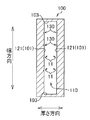
- FIG. 9 is a cross-sectional view showing a transfer pipe according to a third embodiment of the present invention.
- the third embodiment of the present invention shown in FIG. 9 is characterized in that the wall flow generation unit 130 is configured by a recess (concave surface) formed in the opposing surface.
- symbol is attached
- the transport pipe 100 forms a transport path 110 for transporting the transported object by an air flow.
- the first inner wall 101 of the transport pipe 100 doubles as the facing surface (facing member) 121 described above, and the facing surface 121 faces both main surfaces of the object to be transported.
- a plurality of wall flow generation units 130 are formed on the facing surfaces 121.
- the plurality of wall flow generating portions 130 are concave portions 137 as concave portions or concave portions as illustrated in FIG. 10.
- the plurality of wall flow generation units 130 generate a wall flow that prevents adsorption of the transported object to be transported to the first inner wall 101.
- FIGS. 10 (a) to 10 (c) are diagrams for explaining an example of the shape of the wall flow generation unit 130 according to the third embodiment of the present invention shown in FIG.
- the partial enlarged longitudinal cross-sectional view of a wall flow generation part is shown.
- the wall flow generation unit 130 is a concave portion 137 formed on the facing surface 121 or a concave surface 137 as a recess.
- the concave surface 137 as the wall flow generation unit 130 is an example having a perfect circular shape in plan view.
- the longitudinal cross-sectional shape of the wall flow generation unit 130 is an arc shape, an oval shape, or the like.
- the deepest part 135 of the wall flow generation part 130 is located in the center part of the conveyance direction, the deepest part 135 of the concave surface 137 as the wall flow generation part 130 may be offset upstream in the conveyance direction.
- the wall flow generation unit 130 is an example having an elliptical shape (or an oval shape) in plan view.
- the longitudinal cross-sectional shape of the wall flow generation unit 130 is an arc shape, an oval shape, or the like.
- the deepest portion 135 of the concave surface 137 as the wall flow generation unit 130 may be offset to the upstream side in the transport direction.
- concave surface 137 as wall flow generation part 130 When wall flow generation part 130 is made into elliptical shape, it is desirable for concave surface 137 as wall flow generation part 130 to be arranged so that the long axis may extend along a conveyance direction. Note that the major axis of the concave surface 137 as the wall flow generation unit 130 may be inclined or orthogonal to the transport direction.
- the concave surface 137 as the wall flow generation unit 130 is an example of a teardrop type or a water drop type in plan view.
- the end corners of the concave surface 137 as the wall flow generation unit 130 are disposed so as to face the downstream side in the transport direction. That is, the increase rate of the widthwise length from the upstream end of the wall flow generation unit 130 in the transport direction to the downstream side is greater than the increase rate of the widthwise length from the downstream end of the wall flow generation unit 130 in the transport direction.
- the wall flow generating unit 130 is disposed to be large. Furthermore, in the concave surface 137 of FIG.
- the major axis extends along the transport direction, similarly to the concave surface 137 of the oval-shaped wall flow generating portion shown in FIG. Although it is desirable to arrange, the major axis may be inclined relative to the transport direction.
- the wall flow generation unit 130 illustrated in FIG. 10C is disposed at a position where the deepest portion 135 is displaced upstream in the transport direction. That is, the gradient from the upstream end of the wall flow generation part 130 to the deepest part 135 is formed to be steeper than the gradient from the downstream end of the wall flow generation part 130 to the deepest part 135.
- the wall flow 11 can be more reliably generated in order to prevent the transported object being transported from being adsorbed to the first inner wall 101.
- the wall flow generation part 130 is a concave portion or a concave surface 137 as a recess
- the plan view of the wall flow generation part 130 In addition to the perfect circular shape, the elliptical shape, and the teardrop shape, the shape of can be a polygonal shape, an oval shape, or any other shape.
- the concave surface 137 of the wall flow generation unit 130 may be formed of a curved surface, or may be formed by combining a plurality of flat surfaces.
- FIG. 10 shows an example in which the wall flow generation units 130 are alternately arranged in the facing surface 121, for example, in a zigzag shape. Since the wall flow generating portions 130 are alternately arranged on the facing surface 121, the plurality of wall flow generating portions 130 form the wall flows 11 in the transport path so as to be substantially uniform without unevenness. Can. For this reason, in order to prevent the transported object being transported from being adsorbed to the first inner wall 101, the wall flow 11 can be reliably generated.
- the wall flow generating units 130 are alternately arranged on the facing surface 121, for example, in a staggered manner, the wall flows 11 generated by the wall flow generating units 130 are generated by the front and rear wall flow generating units 130. Insensitive to wall flow 11.
- the to-be-conveyed object S can be stably conveyed in the conveyance path 110.
- the wall flow generation units 130 may be aligned and arranged in a grid shape (grid shape) on the facing surface 121.
- the relationship between the arrangement quantity of the wall flow generating unit 130 and the area occupied by the main surface of the transported object is as described in the first embodiment (FIG. 3) of the present invention.
- FIG. 11 is a cross-sectional view showing a transfer pipe according to a modification of the third embodiment of the present invention.
- the wall flow generation unit 130 is formed by the concave portion or the concave portion (concave surface 137)
- the opposing plate 120 is disposed at a position separated from the first inner wall 101 and the second inner wall 103 of the transport pipe 100, respectively.
- the wall flow generating unit 130 may be formed on the facing surface 121 of the facing plate 120.
- the angle of the transfer pipe 100 can also be set to an arbitrary angle with respect to the direction of gravity, as described in the first embodiment of the present invention.
- the wall flow generation unit 130 is a concave portion or a recess provided in an opposing surface (opposing member) 121 which also serves as the first inner wall 101 of the transport pipe 100. It is formed by the concave surface 137 as. For this reason, the number of parts constituting the transfer pipe 100 can be reduced, and the internal structure of the transfer pipe 100 can be simplified. Moreover, since the wall flow generation unit 130 can be formed, for example, by pressing on the opposite surface (opposite member) 121 which also serves as the first inner wall 101 of the transport pipe 100, the wall flow generation unit 130 can be easily formed. It can do.
- the wall flow generation part 130 is formed by a concave portion 137 provided in the opposing plate 120 or a concave surface 137 as a concave.
- the concave surface 137 as the wall flow generation unit 130 can be easily formed, for example, by pressing the opposing surface (opposing member) 121 of the opposing plate 120.
- FIG. 12 is a longitudinal sectional view showing a curved portion of a transfer pipe according to a fourth embodiment of the present invention.
- tube 100 curves (or bending) is shown.
- the transfer pipe of the airflow transfer device has, for example, a curved structure, a ring-shaped structure, or a branched structure along a required transfer path. Structure.
- the flow velocity of the main conveyance air flow 10c on the outer circumferential side of the conveyance path 110 is faster than the flow velocity of the main conveyance air flow 10d on the inner circumferential side.
- At least one of the number and the area of the wall flow generation portion 130 is divided into another portion (straight line in the curved portion outer peripheral upstream region 115 and the curved portion inner peripheral downstream region 117).
- the wall flow 11 in the curved portion outer peripheral upstream region 115 and the curved portion inner peripheral downstream region 117 is increased by increasing the number of conveyance paths.
- the viscous drag of the curved portion outer peripheral upstream region 115 and the curved portion inner peripheral downstream region 117 is reduced to the limit, and the generation of the turbulent flow is prevented.
- the object S can be pushed back to the central portion of the transport path 110 by the wall flow 11. For this reason, adhesion to the opposing surface 121 of the to-be-conveyed object S is prevented, and smooth direction change is implement
- the above-described airflow transport device 1 forms a transport path 110 for transporting the sheet-like or thin-plate-like transported object S by air flow, and is transported along the transport path 110.
- a transport pipe 100 having two main inner walls (for example, the first inner wall 101) parallel to both main surfaces S1 and S1 of the object and a main transport air stream 10 from one of the transport paths 110 to the other into the transport path 110
- the opposing plate 120 as the opposing member forming the transport path 110 between the opposing surfaces 121 and the opposing plates 120 are respectively formed to prevent the transported object S being conveyed from contacting or adsorbing to the opposing surface 121
- the wall flow 11 is an air flow that acts to prevent the transported object S being transported from approaching, coming into contact with, or adsorbing to the facing surface 121.
- the wall flow 11 is a minute vortex flow generated on the facing surface 121 and functioning like a cushion between the carried object S and the facing surface 121 even if the air flow is blown toward the carried object S.
- Such a wall flow 11 may be generated by a wall flow generation portion 130 having a through hole 131 formed in the opposing member 120 and a wall flow generation portion 130 having a bottom with a recess formed on the opposing surface 121. , Has been confirmed by the inventor's experiments. By generating the wall flow 11, it is possible to reduce the viscous drag between the opposing surface 121 and the air.
- the upper critical Reynolds number can be increased, and the main transport air stream 10 maintains the laminar flow even when the flow velocity of the main transport air stream is increased. It can prevent flutter. Furthermore, the wall flow 11 pushes back the transferred object toward the central portion of the transfer path 110 when the transferred object S approaches the facing surface 121, and the transferred object S contacts or adsorbs to the facing surface 121. To prevent.
- each wall flow generation unit 130 is formed to penetrate the opposing member 120, and each wall flow generation unit 130 includes the opposing member 120 and each main inner wall (first It is characterized in that it has a through hole 131 communicating the first air flow passage 111 formed between it and the inner wall 101) and the transport passage 110.
- the through holes 131 of the wall flow generation units 130 are flow paths for supplying the air of the first air flow path 111 to the transport path 110, and generate wall flows 11 to be sprayed toward the transported object.
- the through hole 131 is formed to penetrate the opposing plate 120, and the through hole 131 communicates the first air flow passage 111 with the transport passage 110. For this reason, since the wall flow 11 is formed from the first air flow passage 111 side to the conveyance path 110 side, it is possible to prevent the transported object S being conveyed from contacting or adsorbing to the facing surface 121.
- each wall flow generation unit 130 extends from the peripheral edge 131 b excluding the upstream end edge 131 a of the through hole 131 to the first air flow path 111 side.
- a guide member 133 for guiding the air flow in the air flow passage 111 to the conveyance path 110 via the through hole 131 is provided.
- the guide member 133 can cause the air flow introduced from the first air flow passage 111 side to be jetted obliquely toward the conveyance path 110 as the wall flow 11 toward the conveyance path 110 side. For this reason, it can prevent that the to-be-conveyed object S in conveyance contacts or adsorb
- the guide member 133 preferably includes a guide surface 133 a as an inclined surface which is inclined toward the first air flow passage 111 from the downstream end edge of the through hole 131 toward the upstream side.
- the guide surface 133a of the guide member 133 can ensure that the air flow introduced from the first air flow passage 111 side is jetted obliquely toward the conveyance passage 110 as the wall flow 11 toward the conveyance passage 110 side. it can.
- the length of the through hole 131 in the width direction orthogonal to the transfer direction gradually decreases toward the downstream side in the transfer direction. According to this aspect, the air flow introduced from the first air flow passage 111 side can be reliably ejected as the wall flow 11 to the transport path 110 side.
- the airflow transfer device 1 is characterized in that the second air flow passage 113 for introducing the air flow in the transfer passage 110 into the first air flow passage 111 is provided.
- the wall flow 11 generated in the process of flowing into the conveyance path 110 from the through hole 131 returns to the first air flow path 111 as the return flow 13 from the second air flow path 113, and the conveyance path from the through hole 131 again. It flows into 110 and generates wall flow 11 again. Therefore, the wall flow 11 can be formed more reliably.
- the wall flow generation unit 130 is a bottomed recess (concave surface 137) formed in the facing surface 121.
- the number of parts constituting the transfer pipe 100 can be reduced, and the internal structure of the transfer pipe 100 can be simplified.
- the wall flow generation unit 130 can be formed, for example, by pressing on the opposite surface (opposite member) 121 which also serves as the first inner wall 101 of the transport pipe 100, the wall flow generation unit 130 can be easily formed. It can do.
- the depth of the recess (concave surface 137) from the facing surface 121 is deep on the upstream side in the transport direction of the article S and shallow on the downstream side in the transport direction. It is characterized by According to this aspect, the recess (concave surface 137) can reliably form the wall flow 11 on the transport path 110 side.
- the wall flow generation units 130 are characterized in that they are alternately arranged in the transfer direction of the object S to be transferred.
- the plurality of wall flow generation units 130 can form the wall flow 11 in the transport path 110 so as to be substantially uniform without unevenness. Therefore, the wall flow 11 can be reliably generated to prevent the transported object S being transported from being adsorbed to the first inner wall 101.
- the wall flow generation units 130 are alternately arranged on the facing surface 121, for example, in a staggered manner, the wall flows 11 generated by the wall flow generation units 130 are the front and rear wall flow generation units 130. It is not easily affected by the generated wall flow 11. For this reason, since the stable wall flow 11 can be formed in the conveyance path 110, the to-be-conveyed object S can be stably conveyed in the conveyance path 110.
- the wall flow generation portion in the portion where the pressure loss of the main transport air flow 10 increases (the curved portion outer peripheral upstream region 115, the curved portion inner peripheral downstream region 117). It is characterized in that at least one of the quantity and size of 130 is increased over the other parts. According to this aspect, in the curved portion outer peripheral upstream region 115 and the curved portion inner peripheral downstream region 117, the viscosity of the curved portion outer peripheral upstream region 115 and the curved portion inner peripheral downstream region 117 is increased by increasing the wall flow 11. As much as possible to prevent the occurrence of turbulence.
- the transported object S can be pushed back to the central portion of the conveying path 110 by the wall flow 11.
- the adhesion of the conveyed object S to the opposing surface 121 is prevented, and the smooth direction change is realized along the curved portion (or the bent portion) of the conveyed object S. For this reason, the to-be-conveyed object S can be stably conveyed by an air flow.
- the airflow transfer device 1 forms a transport path 110 for transporting the sheet-like or thin plate-like transport object S by air flow, and the transport object transported along the transport path.
- a transport pipe 100 having two main inner walls (first inner walls) respectively opposing the main surfaces S1 of the first and second embodiments, and an air flow generator 20 for generating a main transport air flow 10 from one side of the transport path to the other in the transport path 110
- a plurality of wall flow generating portions 130 each comprising a concave surface 137 which is a wall flow 11 which is formed on each main inner wall to prevent the transported object being conveyed from contacting or adsorbing to the main inner wall.
- the wall flow generation unit 130 generates the wall flow 11 on the opposing surface 121 of the opposing member 120, so the auxiliary member for conveyance conventionally required is unnecessary.
- the object S can be stably conveyed by the air flow while preventing deformation of the object S such as paper sheets.
- the plurality of wall flow generating portions 130 are formed of the concave surface 137 which is a concave, the number of parts of the transfer pipe 100 can be reduced and the structure of the transfer pipe 100 can be simplified.
- the conveyance pipe 100 is formed in linear form as an example, and the conveyance direction of the to-be-conveyed object S is linear form.
- the present invention is not limited to this, and the transport pipe 100 may be formed by curving or bending, so that the transport direction of the object S may be a curve, or a plurality of transport pipes 100 may be connected from one transport pipe 100. It may be branched and formed.
- the airflow transfer device can be applied to, for example, a game arcade provided with a game machine such as a pachinko machine or a slot machine. That is, the airflow transfer device according to the embodiment of the present invention directs the bill, which is the transferred object inserted from the bill insertion portion of each gaming machine, to the bill stacking unit through the island facility disposed on the back side of the gaming machine. Useful for long distance transport.
- the shape of the wall flow generation unit 130 is not limited to the illustrated example, and any shape can be adopted.
- the concave surface 137 which is a recess of the wall flow generation unit 130 illustrated in FIG. 10 may have a dimple or spoon cut shape.
- the counter plate 120 including the wall flow generation unit 130 also includes the use of a plate member having a plurality of through holes such as punching metal.
- S object to be transported, S1: main surface, 1: air flow transfer device, 10, 10a to 10d: main transfer air flow, 11, 11a, 11b: wall flow, 13: recurrent flow, 20: air flow generation device, 30: Input port 40: recovery device 100: transport pipe 101: first inner wall (main inner wall) 103: second inner wall 110: transport path 111: first air flow path 113: second air flow path 115 Curved part outer peripheral side upstream region, 117: curved portion inner peripheral side downstream region, 120: opposing plate (example of opposing member), 121, 121a, 121b: opposing surface, 130, 130A: wall flow generating portion, 131: through hole, 131a: upstream end edge, 131b: peripheral edge, 133: guide member, 133a: guide surface, 135: deepest portion, 137: concave surface (concave portion), 200: transport pipe, 201: inner wall surface, 205: transport path, 210 ... air flow
Landscapes
- Engineering & Computer Science (AREA)
- Mechanical Engineering (AREA)
- Physics & Mathematics (AREA)
- Fluid Mechanics (AREA)
- Multimedia (AREA)
- General Physics & Mathematics (AREA)
- Delivering By Means Of Belts And Rollers (AREA)
- Pinball Game Machines (AREA)
- Feeding Of Articles By Means Other Than Belts Or Rollers (AREA)
Abstract
搬送用の補助部材が不要であり、紙葉類等のような被搬送物の変形を防ぎながら、被搬送物を空気流により安定して搬送できる空気流搬送装置を提供する。 空気流搬送装置1は、搬送路110に沿って搬送される被搬送物Sの両主面S1と夫々並行する2つの主内壁としての第一内壁101を有した搬送管100と、搬送路110の一方から他方に向かう主搬送気流10を搬送路110内に発生させる気流発生装置20と、各第一内壁101との間に所定のギャップを隔てて夫々対向配置されて、搬送される被搬送物Sの両主面S1と夫々対向する対向面121を備え、対向面121間に搬送路110を形成する対向部材としての対向板120と、各対向板120に夫々形成されて、搬送中の被搬送物Sが対向面に接触又は吸着することを防止する壁流11を発生させる複数の壁流発生部130を備える。
Description
本発明は、シート状又は薄板状の被搬送物を空気流にて搬送する空気流搬送装置に関する。
従来、紙幣(シート状の被搬送物)の搬送には、紙幣と接触しながら搬送する搬送ベルトや、これを駆動する駆動ローラ等の搬送機構を備えた搬送装置が用いられている。例えば、パチンコ、スロットマシンの遊技場においては、各遊技機の紙幣投入部から投入された紙幣は、遊技機の裏側に配置された島設備に導入されて、紙幣集積部に向けて長距離搬送される。
しかし、従来の搬送装置を用いて紙幣を長距離搬送しようとすると、搬送装置が大型化し、搬送機構の駆動のためのランニングコストが増大するという問題がある。
そこで、近年においては、中空の搬送管内に搬送用の空気流を発生させて、空気流に乗せて紙幣を搬送する搬送装置が提案されている(特許文献1、特許文献2)。しかし、一般的には、紙幣を単に搬送管に挿入して空気流を用いて搬送しようとすると、搬送管の内壁面に紙幣が吸着されて搬送されなくなるという問題がある。
しかし、従来の搬送装置を用いて紙幣を長距離搬送しようとすると、搬送装置が大型化し、搬送機構の駆動のためのランニングコストが増大するという問題がある。
そこで、近年においては、中空の搬送管内に搬送用の空気流を発生させて、空気流に乗せて紙幣を搬送する搬送装置が提案されている(特許文献1、特許文献2)。しかし、一般的には、紙幣を単に搬送管に挿入して空気流を用いて搬送しようとすると、搬送管の内壁面に紙幣が吸着されて搬送されなくなるという問題がある。
図13は、従来例に係る搬送管の模式図であり、図13(a)は斜視図であり、図13(b)は図13(a)のC-C断面図である。
搬送管200は、四つの平滑な内壁面201によって形成される四角柱状の搬送路205を有する。搬送管200は、搬送路205内に長手方向の一方から他方に向かって流れる空気流210を発生させると共に、長手方向の一方から紙幣220を搬送管200内に挿入する。
しかし、紙幣220を概ね搬送路205に沿って伸長した姿勢とした場合には、紙幣220の搬送上、以下のような問題が生じる。
搬送管200は、四つの平滑な内壁面201によって形成される四角柱状の搬送路205を有する。搬送管200は、搬送路205内に長手方向の一方から他方に向かって流れる空気流210を発生させると共に、長手方向の一方から紙幣220を搬送管200内に挿入する。
しかし、紙幣220を概ね搬送路205に沿って伸長した姿勢とした場合には、紙幣220の搬送上、以下のような問題が生じる。
第一の問題は、紙幣220の主面221と対向する搬送管200の内壁面201に紙幣220が吸着されてしまい、紙幣220が搬送できなくなるという問題である。これは、紙幣220が搬送管200の内壁面201に偏った場合に、偏った側の空気流の流速が速くなって、紙幣220と内壁面201との間が負圧となり、紙幣220が内壁面201に引き寄せられるためと考えられる。
第二の問題は、搬送管200内を流れる空気流210を高速化すると乱流が発生し、紙幣220を搬送できなくなるという問題である。搬送管200内を流れる空気流210の速度が比較的遅い場合には、搬送管200内を流れる空気流210は、搬送管200の長手方向に沿って規則正しく運動する層流を維持する。
第二の問題は、搬送管200内を流れる空気流210を高速化すると乱流が発生し、紙幣220を搬送できなくなるという問題である。搬送管200内を流れる空気流210の速度が比較的遅い場合には、搬送管200内を流れる空気流210は、搬送管200の長手方向に沿って規則正しく運動する層流を維持する。
しかし、搬送管200内を流れる空気流210の速度がある値を超えて高速化すると、空気流が搬送管200の内壁面201に衝突することが原因で、搬送管200内に乱流が発生する。乱流は、空気流が搬送管200内で不規則に運動する流れの状態である。搬送管200内で乱流が発生すると、紙幣220が搬送管200内でばたつき、最終的には紙幣220が内壁面201に吸着、接触して搬送されなくなるか、搬送不良に陥る。
搬送管を利用して空気流により紙幣を搬送するために、特許文献1においては、紙幣の後端部をJ字状に湾曲変形させ、湾曲変形部に搬送用の空気流の風圧を作用させることにより、紙幣の搬送を実現している。また、特許文献2においては、押し込みユニット(ビュレット、搬送補助体)を紙幣の後方に配置して、押し込みユニットが紙幣を後方から押し込むことで、紙幣の搬送を実現している。
搬送管を利用して空気流により紙幣を搬送するために、特許文献1においては、紙幣の後端部をJ字状に湾曲変形させ、湾曲変形部に搬送用の空気流の風圧を作用させることにより、紙幣の搬送を実現している。また、特許文献2においては、押し込みユニット(ビュレット、搬送補助体)を紙幣の後方に配置して、押し込みユニットが紙幣を後方から押し込むことで、紙幣の搬送を実現している。
しかし、上記従来技術には、以下のような問題がある。
特許文献1においては、紙葉類を変形させる為に、紙葉類の搬送先である紙葉類収納部での詰まりが発生する原因となっていた。また、紙葉類が有する癖、皺、よれ具合、コシの強さ等は紙葉類毎に異なっているために、搬送中に維持するべき変形形状が一定とならず、搬送管内での詰まりの要因となっていた。更に、搬送のために変形させた紙葉類を搬送後に伸長させる必要があるため、紙幣の変形と伸長を繰り返すことで、紙葉類の劣化が加速するという問題もある。
特許文献2においては、押し込みユニットを用いて紙葉類を強制的に押し出すため、紙葉類が内壁面に強力に吸着した場合には紙葉類が圧縮変形し、搬送管内での詰まりの要因になると共に、紙葉類に致命的なダメージが加わるといった問題がある。また、押し込みユニット方式は風量の影響を受けやすく、湾曲部の搬送や長距離搬送には不向きである。
また、空気流を用いて紙葉類を水平方向に搬送する従来の技術では、紙葉類の幅方向が重力方向となる姿勢での搬送に限定されており、紙葉類を水平にした姿勢で搬送することはできなかった。
特許文献1においては、紙葉類を変形させる為に、紙葉類の搬送先である紙葉類収納部での詰まりが発生する原因となっていた。また、紙葉類が有する癖、皺、よれ具合、コシの強さ等は紙葉類毎に異なっているために、搬送中に維持するべき変形形状が一定とならず、搬送管内での詰まりの要因となっていた。更に、搬送のために変形させた紙葉類を搬送後に伸長させる必要があるため、紙幣の変形と伸長を繰り返すことで、紙葉類の劣化が加速するという問題もある。
特許文献2においては、押し込みユニットを用いて紙葉類を強制的に押し出すため、紙葉類が内壁面に強力に吸着した場合には紙葉類が圧縮変形し、搬送管内での詰まりの要因になると共に、紙葉類に致命的なダメージが加わるといった問題がある。また、押し込みユニット方式は風量の影響を受けやすく、湾曲部の搬送や長距離搬送には不向きである。
また、空気流を用いて紙葉類を水平方向に搬送する従来の技術では、紙葉類の幅方向が重力方向となる姿勢での搬送に限定されており、紙葉類を水平にした姿勢で搬送することはできなかった。
本発明は上述の事情に鑑みてなされたものであり、搬送用の補助部材が不要であり、紙葉類等のような被搬送物の変形を防ぎながら、被搬送物を空気流により安定して搬送でき、更に重力方向に対して被搬送物の主面の角度を自由な角度に設定して被搬送物を搬送可能な、新規な空気流搬送装置を提供することを目的とする。
上記の課題を解決するために、本発明の空気流搬送装置は、シート状又は薄板状の被搬送物を気流により搬送する搬送路を形成し、該搬送路に沿って搬送される前記被搬送物の両主面と夫々並行する2つの主内壁を有した搬送管と、前記搬送路の一方から他方に向かう主搬送気流を前記搬送路内に発生させる気流発生装置と、前記各主内壁との間に所定のギャップを隔てて夫々対向配置されて、搬送される前記被搬送物の両主面と夫々対向する対向面を備え、該対向面間に前記搬送路を形成する対向部材と、前記各対向部材に夫々形成されて、搬送中の前記被搬送物が前記対向面に接触又は吸着することを防止する壁流を発生させる複数の壁流発生部と、を備えたことを特徴とする。
また、上記の課題を解決するために、本発明の空気流搬送装置は、シート状又は薄板状の被搬送物を気流により搬送する搬送路を形成し、該搬送路に沿って搬送される前記被搬送物の両主面と夫々対向する2つの主内壁を有した搬送管と、前記搬送路の一方から他方に向かう主搬送気流を前記搬送路内に発生させる気流発生装置と、前記各主内壁に夫々形成されて、搬送中の前記被搬送物が前記主内壁に接触又は吸着することを防止する壁流を発生させる凹所から成る複数の壁流発生部と、を備えたことを特徴とする。
また、上記の課題を解決するために、本発明の空気流搬送装置は、シート状又は薄板状の被搬送物を気流により搬送する搬送路を形成し、該搬送路に沿って搬送される前記被搬送物の両主面と夫々対向する2つの主内壁を有した搬送管と、前記搬送路の一方から他方に向かう主搬送気流を前記搬送路内に発生させる気流発生装置と、前記各主内壁に夫々形成されて、搬送中の前記被搬送物が前記主内壁に接触又は吸着することを防止する壁流を発生させる凹所から成る複数の壁流発生部と、を備えたことを特徴とする。
本発明の空気流搬送装置によれば、搬送用の補助部材が不要であり、紙葉類等のような被搬送物の変形を防ぎながら、被搬送物を空気流により安定して搬送できる。
以下に、本発明の好ましい実施形態の空気流搬送装置を、図面を参照して詳しく説明する。本発明の理解のために、本発明の原理をまず図1を参照しながら説明して、その後に本発明の各実施形態を、図2以降を参照して順次詳細に説明する。
本発明の実施形態は、本発明の好ましい具体的な例であり、技術的に好ましい種々の限定が付されている。しかし、本発明の特許請求の範囲は、以下の説明において特に本発明を限定する旨の記載がない限り、これらの態様に限定されない。また、本発明の各実施形態では、同様の構成要素には同一の符号を付して、構成要素の詳細な説明は適宜省略する。
本発明の実施形態は、本発明の好ましい具体的な例であり、技術的に好ましい種々の限定が付されている。しかし、本発明の特許請求の範囲は、以下の説明において特に本発明を限定する旨の記載がない限り、これらの態様に限定されない。また、本発明の各実施形態では、同様の構成要素には同一の符号を付して、構成要素の詳細な説明は適宜省略する。
〔本発明の原理〕
図1(a)、(b)は、本発明の空気流搬送装置の好ましい実施形態が備える搬送管の搬送路の構成を原理的に説明するために、この搬送管の搬送路を模式的に示す概念図であり、図1は、図13のC-C断面に相当する断面図である。
図1に示す搬送管100は、内部に搬送路110を有する。被搬送物Sを搬送するための主搬送気流10(10a、10b)は、搬送管100の搬送路110内に形成されている。主搬送気流10は、搬送路110の長手方向の一方(図中左側)から他方(図中右側)に向かって流れている。
本発明の実施形態においては、壁流11(11a、11b)が、主搬送気流10とは異なる空気流として、搬送路110内に発生されるように構成した点に特徴がある。この壁流11(11a、11b)は、図1(a)に示すように、正規の搬送姿勢で搬送される被搬送物Sの両主面S1、S1と、これらの両主面S1、S1と夫々対向する搬送路110の対向面121(121a、121b)との間において、それぞれ発生される。
図1(a)、(b)は、本発明の空気流搬送装置の好ましい実施形態が備える搬送管の搬送路の構成を原理的に説明するために、この搬送管の搬送路を模式的に示す概念図であり、図1は、図13のC-C断面に相当する断面図である。
図1に示す搬送管100は、内部に搬送路110を有する。被搬送物Sを搬送するための主搬送気流10(10a、10b)は、搬送管100の搬送路110内に形成されている。主搬送気流10は、搬送路110の長手方向の一方(図中左側)から他方(図中右側)に向かって流れている。
本発明の実施形態においては、壁流11(11a、11b)が、主搬送気流10とは異なる空気流として、搬送路110内に発生されるように構成した点に特徴がある。この壁流11(11a、11b)は、図1(a)に示すように、正規の搬送姿勢で搬送される被搬送物Sの両主面S1、S1と、これらの両主面S1、S1と夫々対向する搬送路110の対向面121(121a、121b)との間において、それぞれ発生される。
ここで、壁流11(11a、11b)とは、搬送中の被搬送物Sが対向面121へ接近、接触、或いは吸着することを防止するように作用する空気流のことである。この壁流11(11a、11b)は、被搬送物Sに向けて吹き付ける空気流であっても、対向面121上に発生して被搬送物Sと対向面121との間でクッションのように機能する微少渦流であってもよい。壁流発生部は、後で図2を参照しながら説明するが、搬送路110内に送られる主搬送気流10の状態に応じた壁流11(11a、11b)を発生させる。
この壁流11(11a、11b)は、搬送路110内に送られる主搬送気流10(10a、10b)に対して、被搬送物Sの搬送を補助する搬送補助流とも呼ぶことができる。
この壁流11(11a、11b)は、搬送路110内に送られる主搬送気流10(10a、10b)に対して、被搬送物Sの搬送を補助する搬送補助流とも呼ぶことができる。
図1に示す空気流搬送装置の搬送管100により搬送される被搬送物Sとしては、例えば紙葉類、カード類、札束類等のようなシート状又は薄板状のものであるが、被搬送物Sの材質は特に限定されない。
被搬送物Sが搬送される際の正規の搬送姿勢とは、図1(a)に例示するように、被搬送物Sが、搬送管100内のほぼ中央位置で通過することで、被搬送物Sが搬送路110の対向面121へ接近、接触、或いは吸着しないで、被搬送物Sが圧縮変形の無いように、搬送方向に沿って搬送できる姿勢のことを言う。
被搬送物Sが搬送される際の正規の搬送姿勢とは、図1(a)に例示するように、被搬送物Sが、搬送管100内のほぼ中央位置で通過することで、被搬送物Sが搬送路110の対向面121へ接近、接触、或いは吸着しないで、被搬送物Sが圧縮変形の無いように、搬送方向に沿って搬送できる姿勢のことを言う。
<レイノルズ数>
ここで、空気のような流体のふるまいを特徴付ける値としてレイノルズ数が知られている。流体が層流から乱流に遷移するときのレイノルズ数である上臨界レイノルズ数は、以下のように定義される。
Re=Ud/v ・・・式(1)
但し、U:空気流の流速[m/s]、d:送風管内の断面における代表長さ[m]、v:流体の動粘性係数[m^2/s]。
ここで、空気のような流体のふるまいを特徴付ける値としてレイノルズ数が知られている。流体が層流から乱流に遷移するときのレイノルズ数である上臨界レイノルズ数は、以下のように定義される。
Re=Ud/v ・・・式(1)
但し、U:空気流の流速[m/s]、d:送風管内の断面における代表長さ[m]、v:流体の動粘性係数[m^2/s]。
また、流体の動粘性係数vは以下の式により定義される。
v=μ/q ・・・式(2)
但し、μ:流体の粘性係数[kg/ms]、q:流体の密度[kg/m^3]。
一般的には、図13に例示する通常用いられる搬送管200の内壁面201が平滑面である場合、レイノルズ数Reが2300~4000程度になると、搬送管200内の空気流は層流から乱流に遷移する。
上記式(1)(2)から、粘性係数μを限りなく低下させることができれば、上臨界レイノルズ数Reを限りなく増加させることができる。つまり、層流から乱流に遷移する上臨界レイノルズ数を上昇させることができるので、空気流の流速Uを高めても層流を維持することができる。
v=μ/q ・・・式(2)
但し、μ:流体の粘性係数[kg/ms]、q:流体の密度[kg/m^3]。
一般的には、図13に例示する通常用いられる搬送管200の内壁面201が平滑面である場合、レイノルズ数Reが2300~4000程度になると、搬送管200内の空気流は層流から乱流に遷移する。
上記式(1)(2)から、粘性係数μを限りなく低下させることができれば、上臨界レイノルズ数Reを限りなく増加させることができる。つまり、層流から乱流に遷移する上臨界レイノルズ数を上昇させることができるので、空気流の流速Uを高めても層流を維持することができる。
<壁流による効果>
図1に示すように、本発明の実施形態において、壁流11(11a、11b)が、主搬送気流10(10a、10b)とは異なる空気流として、搬送路110内に発生されることによって、以下の効果が生じる。
第一に、対向面121と空気との粘性抵抗を減少させることができる。
第二に、粘性抵抗の減少によって動粘性係数vを低下させることができ、上臨界レイノルズ数が向上する。即ち、主搬送気流10の流速Uを高めても、層流を維持することができ、被搬送物Sの搬送時のばたつきを防止できる。
第三に、壁流11は、対向面121に接近した被搬送物Sを搬送路110の中央部に向けて押し返して、被搬送物Sが対向面121に吸着することを防止できる。この第三の効果について説明する。
図1に示すように、本発明の実施形態において、壁流11(11a、11b)が、主搬送気流10(10a、10b)とは異なる空気流として、搬送路110内に発生されることによって、以下の効果が生じる。
第一に、対向面121と空気との粘性抵抗を減少させることができる。
第二に、粘性抵抗の減少によって動粘性係数vを低下させることができ、上臨界レイノルズ数が向上する。即ち、主搬送気流10の流速Uを高めても、層流を維持することができ、被搬送物Sの搬送時のばたつきを防止できる。
第三に、壁流11は、対向面121に接近した被搬送物Sを搬送路110の中央部に向けて押し返して、被搬送物Sが対向面121に吸着することを防止できる。この第三の効果について説明する。
図1(a)に示すように、被搬送物Sが、搬送路110の厚さ方向(搬送方向である長手方向と直交する方向)の中央部付近を搬送される場合に、被搬送物Sと夫々の対向面121a、121bとの間を流れる主搬送気流10(10a、10b)の流速及び気圧はほぼ均等であり、夫々の対向面121a、121bにおいて発生する壁流11(11a、11b)の大きさもほぼ均等となる。
図1(b)に示すように、図1(a)の場合と異なり、例えば被搬送物Sが、一方の対向面121a寄りに偏って搬送される場合には、主搬送気流10aの流れは主搬送気流10bの流れよりも速くなる。対向面121aには、主搬送気流10の状態に応じた大きさの壁流11aが発生するため、対向面121aと被搬送物Sの主面S1との間には、高速となった主搬送気流10aに応じた強い壁流11aが発生する。被搬送物Sは、この強い壁流11aにより、図1(a)に示すように、搬送路110の中央部に向けて押し返される。その結果、被搬送物Sは、対向面121aに吸着することなく、搬送路110内をスムーズに搬送される。
図1(b)に示すように、図1(a)の場合と異なり、例えば被搬送物Sが、一方の対向面121a寄りに偏って搬送される場合には、主搬送気流10aの流れは主搬送気流10bの流れよりも速くなる。対向面121aには、主搬送気流10の状態に応じた大きさの壁流11aが発生するため、対向面121aと被搬送物Sの主面S1との間には、高速となった主搬送気流10aに応じた強い壁流11aが発生する。被搬送物Sは、この強い壁流11aにより、図1(a)に示すように、搬送路110の中央部に向けて押し返される。その結果、被搬送物Sは、対向面121aに吸着することなく、搬送路110内をスムーズに搬送される。
〔第一の実施形態〕
本発明の第一の実施形態に係る空気流搬送装置1について、図2を参照して説明する。空気流搬送装置1は、紙幣やカード等の被搬送物Sを空気流により搬送する装置である。
本実施形態に係る空気流搬送装置1は、搬送管100の搬送路110の対向面に壁流を形成することによって、対向面上に壁流を発生させて被搬送物Sの対向面への吸着を防止すると共に、被搬送物Sを搬送する主搬送気流10を層流に維持して、被搬送物Sが搬送方向に沿って安定して搬送されるようにした点に特徴がある。この搬送方向は、搬送管100の搬送路110の長手方向に沿っている。
なお、空気流搬送装置1によって搬送される被搬送物Sには、好ましくはシート状の部材(例:紙幣や有価証券等の紙葉類)、薄板状の部材(例:カード類)、及びこれらの束等を含む。被搬送物Sの材質としては、紙製、プラスチック製、或いは金属箔、その他どのような材質であってもよい。
本発明の第一の実施形態に係る空気流搬送装置1について、図2を参照して説明する。空気流搬送装置1は、紙幣やカード等の被搬送物Sを空気流により搬送する装置である。
本実施形態に係る空気流搬送装置1は、搬送管100の搬送路110の対向面に壁流を形成することによって、対向面上に壁流を発生させて被搬送物Sの対向面への吸着を防止すると共に、被搬送物Sを搬送する主搬送気流10を層流に維持して、被搬送物Sが搬送方向に沿って安定して搬送されるようにした点に特徴がある。この搬送方向は、搬送管100の搬送路110の長手方向に沿っている。
なお、空気流搬送装置1によって搬送される被搬送物Sには、好ましくはシート状の部材(例:紙幣や有価証券等の紙葉類)、薄板状の部材(例:カード類)、及びこれらの束等を含む。被搬送物Sの材質としては、紙製、プラスチック製、或いは金属箔、その他どのような材質であってもよい。
以下の説明において、被搬送物Sの主面とは、被搬送物Sの厚さ方向(搬送方向である長手方向と直交する方向)に伸びる端面以外の広い面のことである。また、被搬送物Sは、搬送時に搬送方向(長手方向)に沿って、概ね伸長した姿勢を維持しつつ搬送されるものとする。
図2以降を参照しながら、空気を利用して被搬送物Sを搬送する空気流搬送装置1について説明するが、被搬送物Sを搬送する気体としては、好ましくは空気であるが、空気以外の気体、流体を用いてもよい。
本発明は、図示した好ましい実施形態に基づいて説明するが、この実施形態に記載される構成要素、種類、組み合わせ、形状、その相対配置などは特定的な記載がない限り、この発明の範囲をそれのみに限定する主旨ではなく単なる説明例に過ぎない。
搬送管100の搬送路110について、被搬送物Sの搬送方向に沿った方向を長手方向、被搬送物Sの幅方向に沿った方向を幅方向、長手方向と幅方向の双方に直交する方向を厚さ方向として説明する。
図2以降を参照しながら、空気を利用して被搬送物Sを搬送する空気流搬送装置1について説明するが、被搬送物Sを搬送する気体としては、好ましくは空気であるが、空気以外の気体、流体を用いてもよい。
本発明は、図示した好ましい実施形態に基づいて説明するが、この実施形態に記載される構成要素、種類、組み合わせ、形状、その相対配置などは特定的な記載がない限り、この発明の範囲をそれのみに限定する主旨ではなく単なる説明例に過ぎない。
搬送管100の搬送路110について、被搬送物Sの搬送方向に沿った方向を長手方向、被搬送物Sの幅方向に沿った方向を幅方向、長手方向と幅方向の双方に直交する方向を厚さ方向として説明する。
<空気流搬送装置1>
次に、空気流搬送装置1について、詳しく説明する。
図2は、本発明の一実施形態に係る空気流搬送装置1の全体的な構成を示した概略図である。
図2に示すように、空気流搬送装置1は、被搬送物Sを空気流により搬送する搬送路110を形成する搬送管100と、搬送路110の長手方向の一方から他方に向かう(搬送方向に流れる)空気流である主搬送気流10を搬送路110内に発生させる気流発生装置20とを備える。
更に、空気流搬送装置1は、搬送管100の長手方向の中間部適所に配置されて、被搬送物Sを搬送路110内に投入する複数の投入口30と、搬送路110の長手方向の他端部に配置されて搬送されてきた被搬送物Sを回収する回収装置40とを備える。被搬送物Sが紙幣である場合の回収装置40は、例えば紙幣を収容する金庫である。
次に、空気流搬送装置1について、詳しく説明する。
図2は、本発明の一実施形態に係る空気流搬送装置1の全体的な構成を示した概略図である。
図2に示すように、空気流搬送装置1は、被搬送物Sを空気流により搬送する搬送路110を形成する搬送管100と、搬送路110の長手方向の一方から他方に向かう(搬送方向に流れる)空気流である主搬送気流10を搬送路110内に発生させる気流発生装置20とを備える。
更に、空気流搬送装置1は、搬送管100の長手方向の中間部適所に配置されて、被搬送物Sを搬送路110内に投入する複数の投入口30と、搬送路110の長手方向の他端部に配置されて搬送されてきた被搬送物Sを回収する回収装置40とを備える。被搬送物Sが紙幣である場合の回収装置40は、例えば紙幣を収容する金庫である。
図2に示すように、気流発生装置20は、搬送管100の長手方向の一端部(搬送方向の上流側端部)に配置されている。気流発生装置20は、搬送路110内に空気を吹き込むことにより、搬送路110の長手方向の一方から他方に向かう主搬送気流10を発生させる。気流発生装置20が発生する空気流である主搬送気流10は、搬送路110内を層流として均等に流すことができる。
なお、図2に示す例とは異なり、気流発生装置20は、上述したように搬送管100の長手方向の他端部(搬送方向の下流側端部)に配置されて、搬送路110内の空気を吸入して外部に排気することにより、主搬送気流10を発生させる装置でもよい。また、気流発生装置20は、搬送管100の長手方向の中間部に配置されて、搬送路110から空気を吸引するか又は搬送路110内に空気を流入させることにより、主搬送気流10を発生させる装置でもよい。さらに、気流発生装置20は、空気流搬送装置1に複数備えられてもよい。
図2には、一例として直線的な搬送路110を有する搬送管100を備える空気流搬送装置1を示しているが、搬送管100の搬送路110は湾曲又は屈曲していてもよく、空気流搬送装置1は、気流発生装置20が発生させた主搬送気流を循環させる環状の搬送路110を備えていてもよい。また、空気流搬送装置1は分岐を有する搬送路110を備えていてもよい。
なお、図2に示す例とは異なり、気流発生装置20は、上述したように搬送管100の長手方向の他端部(搬送方向の下流側端部)に配置されて、搬送路110内の空気を吸入して外部に排気することにより、主搬送気流10を発生させる装置でもよい。また、気流発生装置20は、搬送管100の長手方向の中間部に配置されて、搬送路110から空気を吸引するか又は搬送路110内に空気を流入させることにより、主搬送気流10を発生させる装置でもよい。さらに、気流発生装置20は、空気流搬送装置1に複数備えられてもよい。
図2には、一例として直線的な搬送路110を有する搬送管100を備える空気流搬送装置1を示しているが、搬送管100の搬送路110は湾曲又は屈曲していてもよく、空気流搬送装置1は、気流発生装置20が発生させた主搬送気流を循環させる環状の搬送路110を備えていてもよい。また、空気流搬送装置1は分岐を有する搬送路110を備えていてもよい。
<搬送管100>
次に、搬送管100について、図3を参照して説明する。
図3は、本発明の第一の実施形態に係る搬送管100を示す図であり、図3(a)は横断面図であり、図3(b)は図3(a)のB-B断面図であり、図3(c)は図3(a)のC-C断面図である。なお、図3(a)は、被搬送物Sの搬送方向と直交する面にて切断した断面図であり、図2のA-A断面に相当する図である。
次に、搬送管100について、図3を参照して説明する。
図3は、本発明の第一の実施形態に係る搬送管100を示す図であり、図3(a)は横断面図であり、図3(b)は図3(a)のB-B断面図であり、図3(c)は図3(a)のC-C断面図である。なお、図3(a)は、被搬送物Sの搬送方向と直交する面にて切断した断面図であり、図2のA-A断面に相当する図である。
図3に示す搬送管100は、特に図3(a)と図3(c)に示すように、複数の対向板(対向部材)120と、複数の壁流発生部130とを備えている。各対向板(対向部材)120は、被搬送物Sの両主面S1、S1と夫々対向する対向面121、121を有する。壁流発生部130は、対向板120にそれぞれ形成されており、壁流発生部130は、搬送中の被搬送物Sの対向板120への吸着を防止する壁流11を発生させる。
図3(a)に示すように、搬送管100は、横断面形状が概略矩形状の中空空間を有するダクトである。搬送管100は、図3(a)と図3(c)に示す長手方向(搬送方向)に沿って伸びると共に互いに対向する搬送管100の第一内壁101、101と、図3(a)と図3(b)に示す第二内壁103、103とを備える。搬送管100の第一内壁101、101は、搬送される被搬送物Sの主面S1、S1に沿った方向に伸びる比較的広い面であり、搬送管100の第二内壁103、103は搬送管100の第一内壁101、101と略直交する比較的狭い面である。
図3(a)に示すように、搬送管100は、横断面形状が概略矩形状の中空空間を有するダクトである。搬送管100は、図3(a)と図3(c)に示す長手方向(搬送方向)に沿って伸びると共に互いに対向する搬送管100の第一内壁101、101と、図3(a)と図3(b)に示す第二内壁103、103とを備える。搬送管100の第一内壁101、101は、搬送される被搬送物Sの主面S1、S1に沿った方向に伸びる比較的広い面であり、搬送管100の第二内壁103、103は搬送管100の第一内壁101、101と略直交する比較的狭い面である。
図3(a)から図3(c)に示すように、搬送管100内には、搬送方向に沿って伸びる一対の対向板120、120が、搬送方向に沿って平行に配置されている。図3(a)と図3(c)に示すように、対向板120、120の間には、搬送路110が形成されている。
図3(a)と図3(c)に示すように、対向板120、120は、搬送管100の第一内壁101、101から所定の間隔を設けることで離して配置されており、対向板120、120と搬送管100の第一内壁101、101との間には、第一気流路111、111が形成されている。また、図3(a)と図3(b)に示すように、対向板120、120は、第二内壁103、103から所定の間隔を設けることで離して配置されている。
図3(a)と図3(b)に示すように、対向板120、120と第二内壁103、103との間の領域には、第二気流路113、113が形成されている。第一気流路111、111は、対向板120、120を間に挟んで搬送路110と並行に配置されている。
対向板120、120は、例えば搬送管100の第一内壁101、101又は第二内壁103、103に取り付けられた複数の固定部材としてのステー(不図示)によって支持される。ステーは、好ましくは搬送管100の長手方向に沿って所定の間隔を開けて配置されており、搬送管100内での各種の空気流を阻害しない位置において対向板120を支持する。
図3(a)と図3(c)に示すように、対向板120、120は、搬送管100の第一内壁101、101から所定の間隔を設けることで離して配置されており、対向板120、120と搬送管100の第一内壁101、101との間には、第一気流路111、111が形成されている。また、図3(a)と図3(b)に示すように、対向板120、120は、第二内壁103、103から所定の間隔を設けることで離して配置されている。
図3(a)と図3(b)に示すように、対向板120、120と第二内壁103、103との間の領域には、第二気流路113、113が形成されている。第一気流路111、111は、対向板120、120を間に挟んで搬送路110と並行に配置されている。
対向板120、120は、例えば搬送管100の第一内壁101、101又は第二内壁103、103に取り付けられた複数の固定部材としてのステー(不図示)によって支持される。ステーは、好ましくは搬送管100の長手方向に沿って所定の間隔を開けて配置されており、搬送管100内での各種の空気流を阻害しない位置において対向板120を支持する。
ただし、対向板120、120は、例えば搬送管100の第一内壁101、101又は第二内壁103、103に対して、間隔を設けるようにして、例えば固定部材としてのスタッドやカラー等を用いて固定しても良い。
対向板120間の幅は、好ましくは9mmから16mm程度の範囲で設定することができるが、より好ましくは10mm~13mmの範囲とすることが望ましい。
例えば対向板間が9mm未満であると、折り目や曲がりのある癖札を搬送管に挿入した場合に、対向板120間双方に接触する現象が発生することにより摩擦抵抗が発生し安定して搬送できないので、好ましくない。
また、対向板間が16mmを超えると、搬送管100の体積が大きくなり、気流発生装置20の出力を大きくする必要がある為、好ましくない。
対向板120間の幅は、好ましくは9mmから16mm程度の範囲で設定することができるが、より好ましくは10mm~13mmの範囲とすることが望ましい。
例えば対向板間が9mm未満であると、折り目や曲がりのある癖札を搬送管に挿入した場合に、対向板120間双方に接触する現象が発生することにより摩擦抵抗が発生し安定して搬送できないので、好ましくない。
また、対向板間が16mmを超えると、搬送管100の体積が大きくなり、気流発生装置20の出力を大きくする必要がある為、好ましくない。
図3(b)に例示した例では、複数の壁流発生部130が、対向面121上に、好ましくは互い違いに配置されている状態として、例えば千鳥格子状になるように配置されている。このように、複数の壁流発生部130が、千鳥格子状になるように配置されていると、各壁流発生部130が発生する壁流11は、搬送方向に関して前後に位置する壁流発生部130が発生する壁流11による影響を受け難い。このため、各壁流発生部130は、搬送路110において、安定した壁流11を形成できるので、被搬送物Sは、搬送路110内をより安定して搬送させることができる。
なお、千鳥格子状とは、幅方向に隣接配置された複数の壁流発生部130から成る一つの壁流発生部列が、長手方向前後方向に位置する他の壁流発生部列を構成する個々の壁流発生部との間で幅方向位置をずらして配置されている状態を指称する。
なお、千鳥格子状とは、幅方向に隣接配置された複数の壁流発生部130から成る一つの壁流発生部列が、長手方向前後方向に位置する他の壁流発生部列を構成する個々の壁流発生部との間で幅方向位置をずらして配置されている状態を指称する。
<壁流発生部130>
次に、壁流発生部130について、説明する。
図4は、壁流発生部130の詳細を示す図であり、図4(a)は壁流発生部130の部分拡大斜視図であり、図4(b)は図4(a)のE-E断面図である。
図3(a)から図3(c)に例示したように、複数の壁流発生部130が、対向板120に形成されている。複数の壁流発生部130は、搬送中の被搬送物Sの対向面121への吸着を防止するために、図4(a)と図4(b)に例示するような壁流11を発生させる構造を有する。
次に、壁流発生部130について、説明する。
図4は、壁流発生部130の詳細を示す図であり、図4(a)は壁流発生部130の部分拡大斜視図であり、図4(b)は図4(a)のE-E断面図である。
図3(a)から図3(c)に例示したように、複数の壁流発生部130が、対向板120に形成されている。複数の壁流発生部130は、搬送中の被搬送物Sの対向面121への吸着を防止するために、図4(a)と図4(b)に例示するような壁流11を発生させる構造を有する。
図4(a)と図4(b)に示すように、壁流発生部130は、貫通孔131と、ガイド部材133とを備える。貫通孔131は、対向板120に貫通形成されている。ガイド部材133は、貫通孔131に対応して形成されている。このガイド部材133は、貫通孔131の上流側端縁131aを除いた周縁131bから第一気流路111側へ延出(突出)して形成されている。ガイド部材133は、第一気流路111内の空気流を、貫通孔131を経由して搬送路110へ噴出するための空気導入用の案内部材である。
図4(a)と図4(b)に示すように、ガイド部材133は、ガイド部材133の搬送路110に面した側に、湾曲したガイド面133aを有する。このガイド面133aは、第一気流路111側から流入させた空気流を搬送路110側に壁流11として、搬送路110に向けて斜め方向に噴出させる。
図4(a)と図4(b)に示すように、ガイド部材133は、ガイド部材133の搬送路110に面した側に、湾曲したガイド面133aを有する。このガイド面133aは、第一気流路111側から流入させた空気流を搬送路110側に壁流11として、搬送路110に向けて斜め方向に噴出させる。
ここで、貫通孔131は、好ましくはその幅が搬送方向の下流側に向うほど漸減する形状を有している。これにより、第一気流路111側から流入させた空気流は、湾曲したガイド面133aにより案内されながら、搬送路110側に壁流11として噴出させることができる。また、ガイド部材133は、第一気流路111側への突出量が、搬送方向の上流側に向かうほど漸増する形状である。これにより、第一気流路111側から流入させた空気流は、湾曲したガイド面133aにより案内されながら、搬送路110側に壁流11として確実に噴出させることができる。
図4(b)に示す傾斜角度θは、ガイド面133aの幅方向中央部において対向面121に対して傾斜していることを示す角度である。
このガイド面133aの傾斜角度θは、好ましくは20度から60度程度の範囲で設定することができるが、より好ましくは30度~45度の範囲とすることが望ましい。傾斜角度θが、好ましくは20度~60度の範囲とすると、被搬送物Sが変形することなく、被搬送物Sを搬送路110の搬送方向に沿って安定して搬送することができる。
このガイド面133aの傾斜角度θは、好ましくは20度から60度程度の範囲で設定することができるが、より好ましくは30度~45度の範囲とすることが望ましい。傾斜角度θが、好ましくは20度~60度の範囲とすると、被搬送物Sが変形することなく、被搬送物Sを搬送路110の搬送方向に沿って安定して搬送することができる。
もし、傾斜角度θが、例えば20度未満であると、搬送路110側への壁流11の噴出が弱く壁流11が不足して、被搬送物Sが対向面121に付着しやすくなり、被搬送物Sを搬送路110の搬送方向に沿って安定して搬送できないので、好ましくない。
また、傾斜角度θが、例えば60度を超えると、ガイド面133aに対する反発係数が強くなり壁流11の噴出が弱くなるおそれがあり、被搬送物Sを搬送路110の搬送方向に沿って安定して搬送できず、好ましくはない。
傾斜角度θは、より好ましくは30度~45度の範囲とすると、被搬送物Sが例えば紙幣のようなものである場合には、被搬送物Sが変形することなく、被搬送物Sを搬送路110の搬送方向に沿ってさらに安定して搬送することができる。
この傾斜角度θは、被搬送物Sが例えば紙幣のようなものである場合には、特に好ましくは30度である。本発明者らの実験により、傾斜角度θが30度であると、被搬送物Sは最も安定して搬送方向に搬送することができることが判明している。
また、傾斜角度θが、例えば60度を超えると、ガイド面133aに対する反発係数が強くなり壁流11の噴出が弱くなるおそれがあり、被搬送物Sを搬送路110の搬送方向に沿って安定して搬送できず、好ましくはない。
傾斜角度θは、より好ましくは30度~45度の範囲とすると、被搬送物Sが例えば紙幣のようなものである場合には、被搬送物Sが変形することなく、被搬送物Sを搬送路110の搬送方向に沿ってさらに安定して搬送することができる。
この傾斜角度θは、被搬送物Sが例えば紙幣のようなものである場合には、特に好ましくは30度である。本発明者らの実験により、傾斜角度θが30度であると、被搬送物Sは最も安定して搬送方向に搬送することができることが判明している。
なお、図4(b)に示すように、ガイド部材133は、ガイド面133aの傾斜角度θが搬送方向に一定となる形状でもよいし、第一気流路111側(或いは搬送方向下流側)に凸状に膨出した湾曲形状でもよいし、搬送路110側に凸状に膨出した湾曲形状でもよい。
一例として、被搬送物Sが幅76mm、長さ160mmの紙幣である場合、貫通孔131の大きさは、幅(W)8mm×搬送方向長(L)7mm×深さ(D)2.5mmの三角形の出窓形状とすることができる。
一例として、被搬送物Sが幅76mm、長さ160mmの紙幣である場合、貫通孔131の大きさは、幅(W)8mm×搬送方向長(L)7mm×深さ(D)2.5mmの三角形の出窓形状とすることができる。
図5は、図4に示す壁流発生部130とは異なる他の例である壁流発生部130Aを示す部分拡大斜視図である。
図5に示すように、壁流発生部130Aは、貫通孔131と、ガイド部材133とを備える。貫通孔131は、対向部材120に貫通形成されている。ガイド部材133は、貫通孔131に対応して形成されている。このガイド部材133は、貫通孔131の上流側端縁131aを除いた周縁131bから第一気流路111側へ延出(突出)して形成されている。ガイド部材133は、第一気流路111内の空気流を、貫通孔131を経由して搬送路110へ導く。
ガイド部材133は、ガイド部材133の搬送路110に面した側に、ガイド面133aを有する。このガイド面133aは、第一気流路111側から流入させた空気流を搬送路110側に壁流11として、搬送路110に向けて斜め方向に噴出させる。
図5に示すように、壁流発生部130Aは、貫通孔131と、ガイド部材133とを備える。貫通孔131は、対向部材120に貫通形成されている。ガイド部材133は、貫通孔131に対応して形成されている。このガイド部材133は、貫通孔131の上流側端縁131aを除いた周縁131bから第一気流路111側へ延出(突出)して形成されている。ガイド部材133は、第一気流路111内の空気流を、貫通孔131を経由して搬送路110へ導く。
ガイド部材133は、ガイド部材133の搬送路110に面した側に、ガイド面133aを有する。このガイド面133aは、第一気流路111側から流入させた空気流を搬送路110側に壁流11として、搬送路110に向けて斜め方向に噴出させる。
図5に示す壁流発生部130Aは、貫通孔131の幅が搬送方向に沿って一定に維持されている点で、図4に示した壁流発生部130とは形状が異なる。しかし、図5に示す壁流発生部130Aのガイド部材133の第一気流路111側への突出量は、搬送方向の上流側に向かうほど漸増する点で、図4に示した壁流発生部130と同様の形状である。壁流発生部130Aは、図4に示した壁流発生部130と同様に、第一気流路111側から流入させた空気流を搬送路110側に壁流11として噴出させることができる。
例えば、図4と図5に示す対向板120が金属平板から構成される場合には、壁流発生部130は、金属平板に対して幅方向に伸びるように形成されたスリット状の切り込みよりも搬送方向下流側を板面から立体的に起こすことにより形成される。壁流発生部130は、例えば射出成型又はルーバー状に開口させる押出し加工により形成することができる。
例えば、図4と図5に示す対向板120が金属平板から構成される場合には、壁流発生部130は、金属平板に対して幅方向に伸びるように形成されたスリット状の切り込みよりも搬送方向下流側を板面から立体的に起こすことにより形成される。壁流発生部130は、例えば射出成型又はルーバー状に開口させる押出し加工により形成することができる。
壁流発生部130の配置及び数量については、図3を参照して説明する。
図3に示すように、搬送される被搬送物Sの大きさ(図3(c)に示す主面S1の占める面積)に対して、壁流発生部130の数が少なすぎると壁流の噴出量が不足して、被搬送物Sが対向面121に接近して付着しやすくなる。また、逆に搬送される被搬送物Sの大きさに対して、壁流発生部130の数が多すぎると、主搬送気流による搬送力が低下する。
従って、搬送される被搬送物Sの大きさに対して適切な数量の壁流発生部130を設けて、被搬送物Sに対して供給する壁流の量を適切に調整する必要がある。
具体的には、壁流発生部130は、被搬送物Sの大きさに対応して、搬送方向に3~5列程度、幅方向に2~5列程度、配置されることが望ましい。つまり、被搬送物Sは搬送中に、常時、搬送方向に3~5列程度、幅方向に2~5列程度の壁流発生部130と対向することが望ましい。一例としては、被搬送物Sが例えば紙幣である場合には、紙幣の長手方向に沿って、例えば最小限で3列の壁流発生部130があれば、紙幣は良好に浮上して搬送方向に安定して搬送できる。被搬送物Sが例えば紙幣である場合には、紙幣の短手方向に沿って、同様に例えば最低限2列あれば、紙幣は良好に浮上して搬送方向に安定して搬送できる。
図3に示すように、搬送される被搬送物Sの大きさ(図3(c)に示す主面S1の占める面積)に対して、壁流発生部130の数が少なすぎると壁流の噴出量が不足して、被搬送物Sが対向面121に接近して付着しやすくなる。また、逆に搬送される被搬送物Sの大きさに対して、壁流発生部130の数が多すぎると、主搬送気流による搬送力が低下する。
従って、搬送される被搬送物Sの大きさに対して適切な数量の壁流発生部130を設けて、被搬送物Sに対して供給する壁流の量を適切に調整する必要がある。
具体的には、壁流発生部130は、被搬送物Sの大きさに対応して、搬送方向に3~5列程度、幅方向に2~5列程度、配置されることが望ましい。つまり、被搬送物Sは搬送中に、常時、搬送方向に3~5列程度、幅方向に2~5列程度の壁流発生部130と対向することが望ましい。一例としては、被搬送物Sが例えば紙幣である場合には、紙幣の長手方向に沿って、例えば最小限で3列の壁流発生部130があれば、紙幣は良好に浮上して搬送方向に安定して搬送できる。被搬送物Sが例えば紙幣である場合には、紙幣の短手方向に沿って、同様に例えば最低限2列あれば、紙幣は良好に浮上して搬送方向に安定して搬送できる。
また、壁流発生部130は、搬送中の被搬送物Sに対して常時平均的な壁流を機能させるために、図3(b)に例示するように、すでに説明したように、搬送方向に沿って互い違い(交互に)に配置されていることが望ましい。しかし、壁流発生部130は、搬送方向に沿って格子状(グリッド状)に配置されていてもよい。
<循環流>
次に、搬送管100内を流れる空気流の循環について、図6を参照して説明する。図6は、搬送管100の一部断面斜視図である。
図6に示すように、搬送管100内を流れる空気流には、主搬送気流10と壁流11の他に、搬送路110から第二気流路113を経由して第一気流路111に向かう回帰流13が存在する。搬送管100内の第一気流路111と第二気流路113の配置位置は、図3(a)と図3(b)を参照してすでに説明している。回帰流13は、壁流11となる空気を搬送路110から第二気流路113を通過して、第一気流路111に供給する。
これにより、搬送管100内の空気は、第一気流路111→貫通孔131→搬送路110→第二気流路113→第一気流路111・・・のように流れて、循環する。つまり、貫通孔131から搬送路110に流入する過程で壁流11を発生させた空気は、第二気流路113から回帰流13として第一気流路111に戻り、再び貫通孔131から搬送路110に流入して壁流11を発生させる。
このように、搬送管100内の空気が循環するので、第一気流路111内の空気と、搬送路110内の空気の密度のバランスが貫通孔131を通じて確保できるので、搬送管100内の空気の流れが安定する。
次に、搬送管100内を流れる空気流の循環について、図6を参照して説明する。図6は、搬送管100の一部断面斜視図である。
図6に示すように、搬送管100内を流れる空気流には、主搬送気流10と壁流11の他に、搬送路110から第二気流路113を経由して第一気流路111に向かう回帰流13が存在する。搬送管100内の第一気流路111と第二気流路113の配置位置は、図3(a)と図3(b)を参照してすでに説明している。回帰流13は、壁流11となる空気を搬送路110から第二気流路113を通過して、第一気流路111に供給する。
これにより、搬送管100内の空気は、第一気流路111→貫通孔131→搬送路110→第二気流路113→第一気流路111・・・のように流れて、循環する。つまり、貫通孔131から搬送路110に流入する過程で壁流11を発生させた空気は、第二気流路113から回帰流13として第一気流路111に戻り、再び貫通孔131から搬送路110に流入して壁流11を発生させる。
このように、搬送管100内の空気が循環するので、第一気流路111内の空気と、搬送路110内の空気の密度のバランスが貫通孔131を通じて確保できるので、搬送管100内の空気の流れが安定する。
また、この循環流の空気は、搬送管100内を循環する過程で主搬送気流10の流れに沿って搬送方向の上流から下流側に流れるので、空気流は対向板120を間に挟んで螺旋状に旋回しながら下流側に流れていくと考えられる。
このように、搬送管100内には、搬送路110の他に、貫通孔131を介して搬送路110と連通する第一気流路111と、搬送路110と第一気流路111とを連通させる貫通孔131とは異なる第二気流路113とを設けたことにより、空気は、搬送管100内で螺旋状に循環させることができる。
このように、搬送管100内には、搬送路110の他に、貫通孔131を介して搬送路110と連通する第一気流路111と、搬送路110と第一気流路111とを連通させる貫通孔131とは異なる第二気流路113とを設けたことにより、空気は、搬送管100内で螺旋状に循環させることができる。
この第二気流路113は、図3(a)に例示するように、搬送管100の第二内壁103と対向板120の幅方向端縁(対向板120の搬送方向に沿った端部)との間に設けることが、循環流を良好に形成する観点から最も望ましい。
空気を搬送管100内で循環させることにより、均一な壁流11が、搬送管100内で途切れることなく連続して発生させることができることから、この均一な壁流11と主搬送気流10は、被搬送物Sを対向面121に付着(接触、吸着)させることなく、被搬送物Sを安定して搬送方向に沿って搬送することができる。
空気を搬送管100内で循環させることにより、均一な壁流11が、搬送管100内で途切れることなく連続して発生させることができることから、この均一な壁流11と主搬送気流10は、被搬送物Sを対向面121に付着(接触、吸着)させることなく、被搬送物Sを安定して搬送方向に沿って搬送することができる。
ここで、図4(a)に示す貫通孔131の幅方向長の最大値をW、対向板120に形成された貫通孔131の幅方向における最大の個数をn、図3(a)に示す第二気流路113の幅方向長(第二内壁103と対向板120の幅方向端縁との距離)をFとした場合に、
W×n≒F×2 ・・・式(3)
を満たすようにすることで、搬送管100内で上記循環流が安定して発生し、被搬送物Sは、安定して効率的に搬送できる。
W×n≒F×2 ・・・式(3)
を満たすようにすることで、搬送管100内で上記循環流が安定して発生し、被搬送物Sは、安定して効率的に搬送できる。
また、図4(b)に示すように貫通孔131の開口の深さ(厚さ方向の長さ)をD、図3(a)と図3(c)に示すように第二気流路113の厚さ方向における長さ(対向板120と第一内壁101との間隔)をGとした場合に、
2×D≒G ・・・式(4)
を満たすようにすることで、搬送管100内で上記循環流が安定して発生し、被搬送物Sは、安定して効率的に搬送方向に搬送できる。
2×D≒G ・・・式(4)
を満たすようにすることで、搬送管100内で上記循環流が安定して発生し、被搬送物Sは、安定して効率的に搬送方向に搬送できる。
式(3)、及び式(4)を満たすことで、図6に示す搬送路110内を流れる主搬送気流10の搬送方向における速度よりも、第一気流路111内を流れる空気流の搬送方向における速度の方が速くなるので、壁流11が均一に発生し、被搬送物Sの搬送を安定させることができる。
<搬送管100の角度>
ここで、搬送管100は、図3(a)に示す搬送管100の幅方向(又は搬送路110の幅方向)が重力方向(鉛直方向或いは上下方向)に沿って伸びるように配置してもよいし、搬送管100の幅方向が重力方向に対して直交するように(つまり搬送管100の幅方向が水平方向に伸びるように)配置してもよいし、搬送管100の幅方向が重力方向に対して任意の方向に伸びるように配置してもよい。即ち、搬送管100の幅方向は、重力方向に対して任意の角度に設定することができる。
本発明の第一の実施形態においては、被搬送物Sの各主面S1に働く壁流11は、重力に抗して被搬送物Sを対向面121から浮き上がらせる効果を有する。従って、搬送管100の幅方向を重力方向に対して任意の角度に設定しても(つまり、搬送中の被搬送物Sの主面S1の角度が重力方向に対して任意の角度となるように搬送管100を設置しても)、被搬送物Sは対向面121に接触することなく、安定して搬送される。
ここで、搬送管100は、図3(a)に示す搬送管100の幅方向(又は搬送路110の幅方向)が重力方向(鉛直方向或いは上下方向)に沿って伸びるように配置してもよいし、搬送管100の幅方向が重力方向に対して直交するように(つまり搬送管100の幅方向が水平方向に伸びるように)配置してもよいし、搬送管100の幅方向が重力方向に対して任意の方向に伸びるように配置してもよい。即ち、搬送管100の幅方向は、重力方向に対して任意の角度に設定することができる。
本発明の第一の実施形態においては、被搬送物Sの各主面S1に働く壁流11は、重力に抗して被搬送物Sを対向面121から浮き上がらせる効果を有する。従って、搬送管100の幅方向を重力方向に対して任意の角度に設定しても(つまり、搬送中の被搬送物Sの主面S1の角度が重力方向に対して任意の角度となるように搬送管100を設置しても)、被搬送物Sは対向面121に接触することなく、安定して搬送される。
<第一の実施形態の効果>
上述した、本発明の第一の実施形態の空気流搬送装置1は、搬送管100を有する。この搬送管100は、被搬送物Sを気流により搬送する搬送路110を形成しており、この搬送路110に沿って正規の搬送姿勢で搬送される被搬送物Sの両主面S1と夫々並行する2つの主内壁としての第一内壁101を有している。気流発生装置20は、搬送路110の一方から他方に向かう主搬送気流10を搬送路110内に発生させる。
対向板120は、各主内壁としての第一内壁101との間に所定のギャップGを隔てて夫々対向配置されて、正規の搬送姿勢で搬送される被搬送物Sの両主面S1と夫々対向する対向面121を備える。対向板120は、対向面121間に搬送路110を形成する対向部材である。
複数の壁流発生部130は、各対向板120に夫々形成されて、搬送中の被搬送物Sが対向面に接触又は吸着することを防止する壁流11を発生させる。これにより、対向板120の各壁流発生部130は、搬送中の被搬送物Sが対向面に接触又は吸着することを防止する壁流11を発生させる。
このため、空気流搬送装置1は、搬送用の補助部材が不要であり、紙葉類等のような被搬送物Sの変形を防ぎながら、被搬送物Sを空気流により安定して搬送できる。
上述した、本発明の第一の実施形態の空気流搬送装置1は、搬送管100を有する。この搬送管100は、被搬送物Sを気流により搬送する搬送路110を形成しており、この搬送路110に沿って正規の搬送姿勢で搬送される被搬送物Sの両主面S1と夫々並行する2つの主内壁としての第一内壁101を有している。気流発生装置20は、搬送路110の一方から他方に向かう主搬送気流10を搬送路110内に発生させる。
対向板120は、各主内壁としての第一内壁101との間に所定のギャップGを隔てて夫々対向配置されて、正規の搬送姿勢で搬送される被搬送物Sの両主面S1と夫々対向する対向面121を備える。対向板120は、対向面121間に搬送路110を形成する対向部材である。
複数の壁流発生部130は、各対向板120に夫々形成されて、搬送中の被搬送物Sが対向面に接触又は吸着することを防止する壁流11を発生させる。これにより、対向板120の各壁流発生部130は、搬送中の被搬送物Sが対向面に接触又は吸着することを防止する壁流11を発生させる。
このため、空気流搬送装置1は、搬送用の補助部材が不要であり、紙葉類等のような被搬送物Sの変形を防ぎながら、被搬送物Sを空気流により安定して搬送できる。
また、各壁流発生部130は、対向部材としての対向板120に貫通形成されており、対向板120と各主内壁101との間に形成される第一気流路111と、搬送路110と、を連通させる貫通孔131を備える。
貫通孔131は、対向板120に貫通形成されており、貫通孔131は、第一気流路111と搬送路110を連通している。このため、壁流11を、第一気流路111側から搬送路110側に発生させることができるので、搬送中の被搬送物Sが対向面121に接触又は吸着することを防止することができる。
さらに、図4と図5に示すように、各壁流発生部130は、貫通孔131の上流側端縁131aを除いた周縁131bから各第一気流路111側へ延出して第一気流路111内の空気流を、貫通孔131を経由して搬送路110へ導くガイド部材133を備える。
これにより、ガイド部材133は、第一気流路111側から流入させた空気流を搬送路110側に壁流11として、搬送路110に向けて斜め方向に確実に噴出させることができる。このため、搬送中の被搬送物Sが、対向面121に接触又は吸着することを防止することができる。
貫通孔131は、対向板120に貫通形成されており、貫通孔131は、第一気流路111と搬送路110を連通している。このため、壁流11を、第一気流路111側から搬送路110側に発生させることができるので、搬送中の被搬送物Sが対向面121に接触又は吸着することを防止することができる。
さらに、図4と図5に示すように、各壁流発生部130は、貫通孔131の上流側端縁131aを除いた周縁131bから各第一気流路111側へ延出して第一気流路111内の空気流を、貫通孔131を経由して搬送路110へ導くガイド部材133を備える。
これにより、ガイド部材133は、第一気流路111側から流入させた空気流を搬送路110側に壁流11として、搬送路110に向けて斜め方向に確実に噴出させることができる。このため、搬送中の被搬送物Sが、対向面121に接触又は吸着することを防止することができる。
図4と図5に示すように、貫通孔131における搬送方向と直交する幅方向における長さが、搬送方向の下流側へ向かう程漸減する。これにより、第一気流路111側から流入させた空気流は、搬送路110側に壁流11として確実に噴出させることができる。
図6に示すように、搬送管100は、搬送路110内の気流を第一気流路111へ導入する第二気流路113を備えている。これにより、搬送管100内を流れる空気流には、主搬送気流10と壁流11の他に、搬送路110から第二気流路113を経由して第一気流路111に向かう回帰流13が形成される。この回帰流13は、壁流11となる空気を搬送路110から第二気流路113を通過して、第一気流路111に供給する。このため、貫通孔131から搬送路110に流入する過程で壁流11を発生させた空気は、第二気流路113から回帰流13として第一気流路111に戻り、再び貫通孔131から搬送路110に流入して壁流11を発生させる。従って、壁流11をより確実に形成することができる。
また、上記壁流11は、対向面121から被搬送物Sを浮き上がらせる効果を有する。従って、搬送管100の幅方向が鉛直方向以外の方向に伸びるように搬送管100を設置したとしても、被搬送物Sは対向面121に接触することなく、安定して搬送される。
図6に示すように、搬送管100は、搬送路110内の気流を第一気流路111へ導入する第二気流路113を備えている。これにより、搬送管100内を流れる空気流には、主搬送気流10と壁流11の他に、搬送路110から第二気流路113を経由して第一気流路111に向かう回帰流13が形成される。この回帰流13は、壁流11となる空気を搬送路110から第二気流路113を通過して、第一気流路111に供給する。このため、貫通孔131から搬送路110に流入する過程で壁流11を発生させた空気は、第二気流路113から回帰流13として第一気流路111に戻り、再び貫通孔131から搬送路110に流入して壁流11を発生させる。従って、壁流11をより確実に形成することができる。
また、上記壁流11は、対向面121から被搬送物Sを浮き上がらせる効果を有する。従って、搬送管100の幅方向が鉛直方向以外の方向に伸びるように搬送管100を設置したとしても、被搬送物Sは対向面121に接触することなく、安定して搬送される。
〔第一の変形実施形態〕
次に、本発明の第一の変形実施形態を、図7を参照して説明する。
図7は、本発明の第一の変形実施形態に係る搬送管を示す横断面図である。以下、本発明の第一の変形実施形態の搬送管100が、上述した本発明の第一の実施形態の搬送管100と同様の機能を有する部位については、同一の符号を付してその説明を適宜省略する。
図7に示すように、第二気流路113、113は、搬送管100の幅方向の中間部に配置してもよい。本例においては、厚さ方向に離間して配置した夫々の対向板120、120を幅方向に二分割することによって、幅方向の中間部に夫々第二気流路113、113が形成されている。2つの第二気流路113、113は、共に搬送路110の搬送方向に沿って延在する気流路である。なお、第二気流路113、113は、搬送路110の搬送方向に断続的に設けられてもよい。
第二気流路113、113を幅方向の中間部に配置したため、図7においては対向板120の片側の幅方向端部は、第二内壁103に密着させた構成としている。
本発明の第一の変形実施形態によっても、循環流が、搬送路110、第二気流路113、第一気流路111、及び貫通孔131を順に流れるように発生するために、壁流11が安定的に発生し、被搬送物Sを安定して効率的に搬送方向に搬送できる。
次に、本発明の第一の変形実施形態を、図7を参照して説明する。
図7は、本発明の第一の変形実施形態に係る搬送管を示す横断面図である。以下、本発明の第一の変形実施形態の搬送管100が、上述した本発明の第一の実施形態の搬送管100と同様の機能を有する部位については、同一の符号を付してその説明を適宜省略する。
図7に示すように、第二気流路113、113は、搬送管100の幅方向の中間部に配置してもよい。本例においては、厚さ方向に離間して配置した夫々の対向板120、120を幅方向に二分割することによって、幅方向の中間部に夫々第二気流路113、113が形成されている。2つの第二気流路113、113は、共に搬送路110の搬送方向に沿って延在する気流路である。なお、第二気流路113、113は、搬送路110の搬送方向に断続的に設けられてもよい。
第二気流路113、113を幅方向の中間部に配置したため、図7においては対向板120の片側の幅方向端部は、第二内壁103に密着させた構成としている。
本発明の第一の変形実施形態によっても、循環流が、搬送路110、第二気流路113、第一気流路111、及び貫通孔131を順に流れるように発生するために、壁流11が安定的に発生し、被搬送物Sを安定して効率的に搬送方向に搬送できる。
〔第二の実施形態〕
次に、本発明の第二の実施形態を、図8を参照して説明する。
図8は、本発明の第二の実施形態に係る搬送管を示す横断面図である。本発明の第二の実施形態の搬送管100は、上述した第一の実施形態の搬送管100と本発明の第一の変形実施形態の搬送管100とは異なり、第二気流路を省略した点に特徴がある。なお、本発明の第二の実施形態に係る搬送管100が、本発明の第一の実施形態の搬送管100と同様の機能を有する部位には同一の符号を付してその説明を適宜省略する。
図8に示すように、搬送管100内に配置された2つの対向板120、120は、夫々第一内壁101、101から離間して配置されており、対向板120、120と第一内壁101、101との間には、第一気流路111、111が形成されている。対向板120、120の幅方向両端部は、第二内壁103、103に対して密着して固定されている。
次に、本発明の第二の実施形態を、図8を参照して説明する。
図8は、本発明の第二の実施形態に係る搬送管を示す横断面図である。本発明の第二の実施形態の搬送管100は、上述した第一の実施形態の搬送管100と本発明の第一の変形実施形態の搬送管100とは異なり、第二気流路を省略した点に特徴がある。なお、本発明の第二の実施形態に係る搬送管100が、本発明の第一の実施形態の搬送管100と同様の機能を有する部位には同一の符号を付してその説明を適宜省略する。
図8に示すように、搬送管100内に配置された2つの対向板120、120は、夫々第一内壁101、101から離間して配置されており、対向板120、120と第一内壁101、101との間には、第一気流路111、111が形成されている。対向板120、120の幅方向両端部は、第二内壁103、103に対して密着して固定されている。
対向板120、120には、本発明の第一の実施形態と同様に、貫通孔(符号省略)を有する複数の壁流発生部130が形成されており、第一気流路111、111を流れる空気は、壁流発生部130の貫通孔を介して搬送路110内に流入して壁流11を発生させる。本発明の第二の実施形態においても、壁流11を発生させる空気を第一気流路111から供給することができるので、壁流11が発生し、被搬送物Sは、対向面121に付着させることなく安定して搬送方向に搬送できる。
なお、壁流11を発生させる空気を第一気流路111から搬送路110に効率的、且つ継続的に供給するために、第一気流路111内において、主搬送気流よりも高速の空気流を、搬送路110を流れる主搬送気流と同方向に流すようにしてもよい。
なお、壁流11を発生させる空気を第一気流路111から搬送路110に効率的、且つ継続的に供給するために、第一気流路111内において、主搬送気流よりも高速の空気流を、搬送路110を流れる主搬送気流と同方向に流すようにしてもよい。
<第二の実施形態の効果>
本発明の第二の実施形態の搬送管100では、対向板120、120の幅方向両端部は、第二内壁103、103に密着して固定されていることで第二気流路を省略する構造を採用している。このため、対向板120、120は、搬送管100の第二内壁103、103に対して確実に固定することができ、搬送管100の構造を簡素化することができる。
本発明の第二の実施形態の搬送管100では、対向板120、120の幅方向両端部は、第二内壁103、103に密着して固定されていることで第二気流路を省略する構造を採用している。このため、対向板120、120は、搬送管100の第二内壁103、103に対して確実に固定することができ、搬送管100の構造を簡素化することができる。
〔第三の実施形態〕
図9は、本発明の第三の実施形態に係る搬送管を示す横断面図である。図9に示す本発明の第三の実施形態では、壁流発生部130は、対向面に形成した凹所(凹面)により構成されている点に特徴がある。なお、本発明の第三の実施形態に係る搬送管100が、本発明の第一の実施形態の搬送管100と同様の機能を有する部材には、同一の符号を付してその説明を適宜省略する。
図9に示すように、搬送管100は、被搬送物を空気流により搬送する搬送路110を形成している。搬送管100の第一内壁101は、すでに説明した対向面(対向部材)121を兼ねており、対向面121は、被搬送物の両主面と夫々対向する。これらの対向面121には、複数の壁流発生部130が形成されている。
複数の壁流発生部130は、図10に例示するような凹状部分もしくは凹所としての凹面137である。複数の壁流発生部130は、搬送中の被搬送物の第一内壁101への吸着を防止する壁流を発生させる。
図9は、本発明の第三の実施形態に係る搬送管を示す横断面図である。図9に示す本発明の第三の実施形態では、壁流発生部130は、対向面に形成した凹所(凹面)により構成されている点に特徴がある。なお、本発明の第三の実施形態に係る搬送管100が、本発明の第一の実施形態の搬送管100と同様の機能を有する部材には、同一の符号を付してその説明を適宜省略する。
図9に示すように、搬送管100は、被搬送物を空気流により搬送する搬送路110を形成している。搬送管100の第一内壁101は、すでに説明した対向面(対向部材)121を兼ねており、対向面121は、被搬送物の両主面と夫々対向する。これらの対向面121には、複数の壁流発生部130が形成されている。
複数の壁流発生部130は、図10に例示するような凹状部分もしくは凹所としての凹面137である。複数の壁流発生部130は、搬送中の被搬送物の第一内壁101への吸着を防止する壁流を発生させる。
図10(a)~図10(c)は、図9に示す本発明の第三の実施形態に係る壁流発生部130の形状例を説明する図であり、夫々対向面121の平面図と壁流発生部の部分拡大縦断面図を示している。部分拡大断面図に示すように、壁流発生部130は、対向面121に形成された凹状部分もしくは凹所としての凹面137である。
図10(a)では、壁流発生部130としての凹面137は、平面で見て真円形状とした例である。壁流発生部130の縦断面形状は、円弧状又は楕円形状等である。壁流発生部130の最深部135は搬送方向の中央部に位置しているが、壁流発生部130としての凹面137の最深部135は、搬送方向の上流側に偏位させてもよい。
図10(b)では、壁流発生部130は、平面で見て楕円形状(或いは、長円形)とした例である。壁流発生部130の縦断面形状は、円弧状又は楕円形状等である。壁流発生部130としての凹面137の最深部135は、搬送方向の上流側に偏位させてもよい。壁流発生部130を楕円形状とする場合には、壁流発生部130としての凹面137は、その長軸が搬送方向に沿って伸びるように配置されることが望ましい。なお、壁流発生部130としての凹面137の長軸は、搬送方向に対して傾斜又は直交させてもよい。
図10(a)では、壁流発生部130としての凹面137は、平面で見て真円形状とした例である。壁流発生部130の縦断面形状は、円弧状又は楕円形状等である。壁流発生部130の最深部135は搬送方向の中央部に位置しているが、壁流発生部130としての凹面137の最深部135は、搬送方向の上流側に偏位させてもよい。
図10(b)では、壁流発生部130は、平面で見て楕円形状(或いは、長円形)とした例である。壁流発生部130の縦断面形状は、円弧状又は楕円形状等である。壁流発生部130としての凹面137の最深部135は、搬送方向の上流側に偏位させてもよい。壁流発生部130を楕円形状とする場合には、壁流発生部130としての凹面137は、その長軸が搬送方向に沿って伸びるように配置されることが望ましい。なお、壁流発生部130としての凹面137の長軸は、搬送方向に対して傾斜又は直交させてもよい。
図10(c)では、壁流発生部130としての凹面137は平面で見て涙型もしくは水滴型とした例である。この場合には、壁流発生部130としての凹面137の先端角部が搬送方向の下流側を向くように配置する。つまり、壁流発生部130の搬送方向の上流端から下流側に向かう幅方向長の増加率が、壁流発生部130の搬送方向の下流端から上流側に向かう幅方向長の増加率よりも大きくなるように、壁流発生部130を配置する。
更に、図10(c)の凹面137は、図10(b)に示した楕円形状の壁流発生部の凹面137と同様に、長軸(最長の内径)が搬送方向に沿って伸びるように配置することが望ましいが、長軸は、搬送方向に対して傾斜させてもよい。
図10(c)に示す壁流発生部130は、部分拡大断面図に示すように、最深部135が搬送方向の上流側に変位した位置に配置されている。即ち、壁流発生部130の上流端から最深部135にかけての勾配は、壁流発生部130の下流端から最深部135にかけての勾配よりも急となるように形成されている。これにより、搬送中の被搬送物が第一内壁101へ吸着するのを防止するために、壁流11をより確実に発生させることができる。
更に、図10(c)の凹面137は、図10(b)に示した楕円形状の壁流発生部の凹面137と同様に、長軸(最長の内径)が搬送方向に沿って伸びるように配置することが望ましいが、長軸は、搬送方向に対して傾斜させてもよい。
図10(c)に示す壁流発生部130は、部分拡大断面図に示すように、最深部135が搬送方向の上流側に変位した位置に配置されている。即ち、壁流発生部130の上流端から最深部135にかけての勾配は、壁流発生部130の下流端から最深部135にかけての勾配よりも急となるように形成されている。これにより、搬送中の被搬送物が第一内壁101へ吸着するのを防止するために、壁流11をより確実に発生させることができる。
以上、図10(a)~図10(c)に基づいて、壁流発生部130が凹状部分もしくは凹所としての凹面137である場合の例について説明したが、壁流発生部130の平面視の形状は、真円形状、楕円形状、涙型以外にも、多角形状やオーバル形状、その他の形状とすることができる。また、壁流発生部130の凹面137は、湾曲面から形成されてもよいし、複数の平面を組み合わせて形成されてもよい。
図10では、壁流発生部130が対向面121において互い違いに、例えば千鳥状になるように配置された例を示している。壁流発生部130が対向面121において互い違いに配置されていることにより、複数の壁流発生部130は、搬送路において、壁流11をムラの無いようにほぼ均一になるように形成することができる。このため、搬送中の被搬送物が第一内壁101へ吸着するのを防止するために、壁流11を確実に発生させることができる。
壁流発生部130が対向面121において互い違いに、例えば千鳥状になるように配置されていると、各壁流発生部130が発生する壁流11は、前後の壁流発生部130が発生する壁流11による影響を受け難い。このため、搬送路110には、安定した壁流11を形成できるので、被搬送物Sは、安定して搬送路110内を搬送させることができる。
なお、壁流発生部130が対向面121において互い違いに配置された例の他に、壁流発生部130は、対向面121において格子状(グリッド状)に整列して配列されてもよい。
壁流発生部130の配置数量と被搬送物の主面の占める面積との関係は、本発明の第一の実施形態(図3)にて説明した通りである。
壁流発生部130が対向面121において互い違いに、例えば千鳥状になるように配置されていると、各壁流発生部130が発生する壁流11は、前後の壁流発生部130が発生する壁流11による影響を受け難い。このため、搬送路110には、安定した壁流11を形成できるので、被搬送物Sは、安定して搬送路110内を搬送させることができる。
なお、壁流発生部130が対向面121において互い違いに配置された例の他に、壁流発生部130は、対向面121において格子状(グリッド状)に整列して配列されてもよい。
壁流発生部130の配置数量と被搬送物の主面の占める面積との関係は、本発明の第一の実施形態(図3)にて説明した通りである。
図11は、本発明の第三の実施形態の変形例に係る搬送管を示す横断面図である。壁流発生部130を凹状部分あるいは凹所(凹面137)により形成する場合であっても、対向板120が、搬送管100の第一内壁101と第二内壁103からそれぞれ離間した位置に配置され、壁流発生部130が対向板120の対向面121に形成されるようにしてもよい。
また、搬送管100の角度についても、本発明の第一の実施形態にて説明したのと同様に、重力方向に対して任意の角度に設定することができる。
また、搬送管100の角度についても、本発明の第一の実施形態にて説明したのと同様に、重力方向に対して任意の角度に設定することができる。
<第三の実施形態の効果>
図9と図10に示す本発明の第三の実施形態では、壁流発生部130は、搬送管100の第一内壁101を兼ねる対向面(対向部材)121において設けられた凹状部分あるいは凹所としての凹面137により形成されている。このため、搬送管100を構成する部品点数を減らして、搬送管100の内部構造の簡素化が図れる。しかも、壁流発生部130は、搬送管100の第一内壁101を兼ねる対向面(対向部材)121に対して、例えばプレスにより形成することができるので、壁流発生部130の形成が簡単に行える。
図11に示す本発明の第三の実施形態の変形例では、壁流発生部130は、対向板120において設けられた凹状部分あるいは凹所としての凹面137により形成されている。このため、壁流発生部130としての凹面137は、対向板120の対向面(対向部材)121に対して、例えばプレスにより簡単に形成できる。
図9と図10に示す本発明の第三の実施形態では、壁流発生部130は、搬送管100の第一内壁101を兼ねる対向面(対向部材)121において設けられた凹状部分あるいは凹所としての凹面137により形成されている。このため、搬送管100を構成する部品点数を減らして、搬送管100の内部構造の簡素化が図れる。しかも、壁流発生部130は、搬送管100の第一内壁101を兼ねる対向面(対向部材)121に対して、例えばプレスにより形成することができるので、壁流発生部130の形成が簡単に行える。
図11に示す本発明の第三の実施形態の変形例では、壁流発生部130は、対向板120において設けられた凹状部分あるいは凹所としての凹面137により形成されている。このため、壁流発生部130としての凹面137は、対向板120の対向面(対向部材)121に対して、例えばプレスにより簡単に形成できる。
〔第四の実施形態〕
図12は、本発明の第四の実施形態に係る搬送管の湾曲部を示す縦断面図である。図12には、搬送管100の搬送路110が湾曲(又は屈曲)する場合の好ましい例を示している。このように搬送管100を湾曲させることで、空気流搬送装置の搬送管は、例えば必要とされる搬送経路に沿って湾曲させた構造にしたり、リング状に形成した構造にしたり、あるいは分岐させた構造にすることができる。
図12に示すように、搬送路110の外周側の主搬送気流10cの流速の方が、内周側の主搬送気流10dの流速よりも速くなる。搬送路110の外周側と搬送路110の内周側との間に発生する主搬送気流10c、10dの流速差のために、搬送路110の湾曲部外周側上流領域115と湾曲部内周側下流領域117においては、乱流(空気流の淀み)が発生する。湾曲部外周側上流領域115と湾曲部内周側下流領域117においては、他の部位に比較してエネルギー損失(圧力損失)が増大する。この乱流は、搬送路110に沿った被搬送物Sの搬送を阻害する。
図12は、本発明の第四の実施形態に係る搬送管の湾曲部を示す縦断面図である。図12には、搬送管100の搬送路110が湾曲(又は屈曲)する場合の好ましい例を示している。このように搬送管100を湾曲させることで、空気流搬送装置の搬送管は、例えば必要とされる搬送経路に沿って湾曲させた構造にしたり、リング状に形成した構造にしたり、あるいは分岐させた構造にすることができる。
図12に示すように、搬送路110の外周側の主搬送気流10cの流速の方が、内周側の主搬送気流10dの流速よりも速くなる。搬送路110の外周側と搬送路110の内周側との間に発生する主搬送気流10c、10dの流速差のために、搬送路110の湾曲部外周側上流領域115と湾曲部内周側下流領域117においては、乱流(空気流の淀み)が発生する。湾曲部外周側上流領域115と湾曲部内周側下流領域117においては、他の部位に比較してエネルギー損失(圧力損失)が増大する。この乱流は、搬送路110に沿った被搬送物Sの搬送を阻害する。
そこで、本発明の第四の実施形態においては、搬送路110が湾曲(又は屈曲)する場合において、エネルギー損失が他の部位よりも比較的大きくなる搬送路110の湾曲部外周側上流領域115と湾曲部内周側下流領域117に対応して形成される壁流発生部130の数量と面積の少なくとも一方を、他の部位よりも増大させた点に特徴がある。
例えば、もし、搬送路110の搬送方向の全域に渡って壁流発生部130の数量と面積を一定にした場合には、搬送中の被搬送物Sは、湾曲部外周側上流領域115において発生する乱流の影響により、湾曲部外周側上流領域115の対向面121に付着して搬送不能になるという問題が発生する。なお、湾曲部内周側下流領域117においても同様の問題が発生する。
例えば、もし、搬送路110の搬送方向の全域に渡って壁流発生部130の数量と面積を一定にした場合には、搬送中の被搬送物Sは、湾曲部外周側上流領域115において発生する乱流の影響により、湾曲部外周側上流領域115の対向面121に付着して搬送不能になるという問題が発生する。なお、湾曲部内周側下流領域117においても同様の問題が発生する。
そこで、本発明の第四の実施形態においては、湾曲部外周側上流領域115と湾曲部内周側下流領域117においては、壁流発生部130の数量と面積の少なくとも一方を、他の部位(直線搬送路)よりも増大させることで、湾曲部外周側上流領域115と湾曲部内周側下流領域117における壁流11を増大させるようにした。このように、壁流11を増大させることで、湾曲部外周側上流領域115と湾曲部内周側下流領域117の粘性抵抗を極限まで低下させて、乱流の発生を防止する。
また、湾曲部外周側上流領域115と湾曲部内周側下流領域117における壁流11を増大させることで、壁流11により被搬送物Sを搬送路110の中心部へと押し戻すことができる。このため、被搬送物Sの対向面121への付着を防止し、被搬送物Sの湾曲部(又は屈曲部)に沿ってスムーズな方向転換を実現する。このため、被搬送物Sは、空気流により安定して搬送方向に沿って搬送できる。
また、湾曲部外周側上流領域115と湾曲部内周側下流領域117における壁流11を増大させることで、壁流11により被搬送物Sを搬送路110の中心部へと押し戻すことができる。このため、被搬送物Sの対向面121への付着を防止し、被搬送物Sの湾曲部(又は屈曲部)に沿ってスムーズな方向転換を実現する。このため、被搬送物Sは、空気流により安定して搬送方向に沿って搬送できる。
<第四の実施形態の効果>
図12に示す本発明の第四の実施形態では、搬送管100の搬送路110が湾曲(又は屈曲)する形状であっても、被搬送物Sは、空気流により安定して搬送できる。このため、搬送管100が曲げて形成されていることで、例えば被搬送物Sの搬送方向が曲線になっている場合や、1つの搬送管100から複数の搬送管100が分岐する場合にも対応して、被搬送物Sは、空気流により安定して搬送できる。
図12に示す本発明の第四の実施形態では、搬送管100の搬送路110が湾曲(又は屈曲)する形状であっても、被搬送物Sは、空気流により安定して搬送できる。このため、搬送管100が曲げて形成されていることで、例えば被搬送物Sの搬送方向が曲線になっている場合や、1つの搬送管100から複数の搬送管100が分岐する場合にも対応して、被搬送物Sは、空気流により安定して搬送できる。
〔本発明の実施態様例と作用、効果のまとめ〕
上述した本発明の好ましい実施形態の空気流搬送装置1は、シート状又は薄板状の被搬送物Sを気流により搬送する搬送路110を形成し、該搬送路110に沿って搬送される被搬送物の両主面S1、S1と夫々並行する2つの主内壁(例えば第一内壁101)を有した搬送管100と、搬送路110の一方から他方に向かう主搬送気流10を搬送路110内に発生させる気流発生装置20と、各主内壁との間に所定のギャップGを隔てて夫々対向配置されて、搬送される被搬送物Sの両主面S1と夫々対向する対向面121を備え、該対向面121間に搬送路110を形成する対向部材としての対向板120と、各対向板120に夫々形成されて、搬送中の被搬送物Sが対向面121に接触又は吸着することを防止する壁流11を発生させる複数の壁流発生部130と、を備えたことを特徴とする。
上述した本発明の好ましい実施形態の空気流搬送装置1は、シート状又は薄板状の被搬送物Sを気流により搬送する搬送路110を形成し、該搬送路110に沿って搬送される被搬送物の両主面S1、S1と夫々並行する2つの主内壁(例えば第一内壁101)を有した搬送管100と、搬送路110の一方から他方に向かう主搬送気流10を搬送路110内に発生させる気流発生装置20と、各主内壁との間に所定のギャップGを隔てて夫々対向配置されて、搬送される被搬送物Sの両主面S1と夫々対向する対向面121を備え、該対向面121間に搬送路110を形成する対向部材としての対向板120と、各対向板120に夫々形成されて、搬送中の被搬送物Sが対向面121に接触又は吸着することを防止する壁流11を発生させる複数の壁流発生部130と、を備えたことを特徴とする。
ここで、壁流11とは、搬送中の被搬送物Sが対向面121へ接近、接触、或いは吸着することを防止するように作用する空気流のことである。壁流11は、被搬送物Sに向けて吹き付ける空気流であっても、対向面121上に発生して被搬送物Sと対向面121との間でクッションのように機能する微少渦流であってもよい。このような壁流11は、対向部材120に貫通形成した貫通孔131を備える壁流発生部130や、対向面121に形成した有底の凹所からなる壁流発生部130により発生することが、本発明者の実験により確認されている。
壁流11を発生させることによって、対向面121と空気との粘性抵抗を減少させることができる。また、動粘性係数を低下させることで、上臨界レイノルズ数を上昇させることができ、主搬送気流の流速を高めても主搬送気流10が層流を維持し、搬送される被搬送物Sのばたつきを防止できる。更に、壁流11は、被搬送物Sが対向面121に接近した場合に被搬送物を搬送路110の中央部に向けて押し返し、被搬送物Sが対向面121に接触又は吸着することを防止する。
壁流11を発生させることによって、対向面121と空気との粘性抵抗を減少させることができる。また、動粘性係数を低下させることで、上臨界レイノルズ数を上昇させることができ、主搬送気流の流速を高めても主搬送気流10が層流を維持し、搬送される被搬送物Sのばたつきを防止できる。更に、壁流11は、被搬送物Sが対向面121に接近した場合に被搬送物を搬送路110の中央部に向けて押し返し、被搬送物Sが対向面121に接触又は吸着することを防止する。
以上のように、本発明の好ましい実施形態の空気流搬送装置1は、壁流発生部130が対向部材120の対向面121に壁流11を発生させるので、従来必要であった搬送用の補助部材が不要であり、紙葉類等のような被搬送物の変形を防ぎながら、被搬送物Sを空気流により安定して搬送できる。
本発明の好ましい実施形態の空気流搬送装置1において、各壁流発生部130は、対向部材120に貫通形成されており、各壁流発生部130は、対向部材120と各主内壁(第一内壁101)との間に形成される第一気流路111と搬送路110とを連通させる貫通孔131を備えることを特徴とする。各壁流発生部130の貫通孔131は、第一気流路111の空気を搬送路110に供給する流路であり、被搬送物に向けて吹き付ける壁流11を発生させる。
本態様によれば、貫通孔131は、対向板120に貫通形成されており、貫通孔131は、第一気流路111と搬送路110を連通している。このため、壁流11は、第一気流路111側から搬送路110側に形成されるので、搬送中の被搬送物Sが対向面121に接触又は吸着することを防止できる。
本発明の好ましい実施形態の空気流搬送装置1において、各壁流発生部130は、対向部材120に貫通形成されており、各壁流発生部130は、対向部材120と各主内壁(第一内壁101)との間に形成される第一気流路111と搬送路110とを連通させる貫通孔131を備えることを特徴とする。各壁流発生部130の貫通孔131は、第一気流路111の空気を搬送路110に供給する流路であり、被搬送物に向けて吹き付ける壁流11を発生させる。
本態様によれば、貫通孔131は、対向板120に貫通形成されており、貫通孔131は、第一気流路111と搬送路110を連通している。このため、壁流11は、第一気流路111側から搬送路110側に形成されるので、搬送中の被搬送物Sが対向面121に接触又は吸着することを防止できる。
本発明の好ましい実施形態の空気流搬送装置1において、各壁流発生部130は、貫通孔131の上流側端縁131aを除いた周縁131bから各第一気流路111側へ延出して第一気流路111内の空気流を、貫通孔131を経由して搬送路110へ導くガイド部材133を備えることを特徴とする。
本態様によれば、ガイド部材133は、第一気流路111側から流入させた空気流を搬送路110側に壁流11として、搬送路110に向けて斜め方向に噴出させることができる。このため、搬送中の被搬送物Sが対向面121に接触又は吸着することを防止することができる。
このガイド部材133は、好ましくは貫通孔131の下流側端縁から上流側に向けて、第一気流路111側に傾斜した傾斜面としてのガイド面133aを備える。これにより、ガイド部材133のガイド面133aは、第一気流路111側から流入させた空気流を搬送路110側に壁流11として、搬送路110に向けて斜め方向に確実に噴出させることができる。
本発明の好ましい実施形態の空気流搬送装置1において、貫通孔131は搬送方向と直交する幅方向における長さが、搬送方向の下流側へ向かう程漸減することを特徴とする。
本態様によれば、第一気流路111側から流入させた空気流は、搬送路110側に壁流11として確実に噴出させることができる。
本態様によれば、ガイド部材133は、第一気流路111側から流入させた空気流を搬送路110側に壁流11として、搬送路110に向けて斜め方向に噴出させることができる。このため、搬送中の被搬送物Sが対向面121に接触又は吸着することを防止することができる。
このガイド部材133は、好ましくは貫通孔131の下流側端縁から上流側に向けて、第一気流路111側に傾斜した傾斜面としてのガイド面133aを備える。これにより、ガイド部材133のガイド面133aは、第一気流路111側から流入させた空気流を搬送路110側に壁流11として、搬送路110に向けて斜め方向に確実に噴出させることができる。
本発明の好ましい実施形態の空気流搬送装置1において、貫通孔131は搬送方向と直交する幅方向における長さが、搬送方向の下流側へ向かう程漸減することを特徴とする。
本態様によれば、第一気流路111側から流入させた空気流は、搬送路110側に壁流11として確実に噴出させることができる。
本発明の好ましい実施形態の空気流搬送装置1において、搬送路110内の気流を第一気流路111へ導入する第二気流路113を備えたことを特徴とする。
本態様によれば、貫通孔131から搬送路110に流入する過程で発生した壁流11は、第二気流路113から回帰流13として第一気流路111に戻り、再び貫通孔131から搬送路110に流入して再び壁流11を発生させる。従って、壁流11は、より確実に形成することができる。
本発明の好ましい実施形態の空気流搬送装置1において、壁流発生部130は、対向面121に形成された有底の凹所(凹面137)であることを特徴とする。
本態様によれば、搬送管100を構成する部品点数を減らして、搬送管100の内部構造の簡素化が図れる。しかも、壁流発生部130は、搬送管100の第一内壁101を兼ねる対向面(対向部材)121に対して、例えばプレスにより形成することができるので、壁流発生部130の形成が簡単に行える。
本発明の好ましい実施形態の空気流搬送装置1において、凹所(凹面137)の対向面121からの深さは、被搬送物Sの搬送方向の上流側において深く、搬送方向の下流側において浅いことを特徴とする。
本態様によれば、凹所(凹面137)は、搬送路110側に壁流11を確実に形成することができる。
本態様によれば、貫通孔131から搬送路110に流入する過程で発生した壁流11は、第二気流路113から回帰流13として第一気流路111に戻り、再び貫通孔131から搬送路110に流入して再び壁流11を発生させる。従って、壁流11は、より確実に形成することができる。
本発明の好ましい実施形態の空気流搬送装置1において、壁流発生部130は、対向面121に形成された有底の凹所(凹面137)であることを特徴とする。
本態様によれば、搬送管100を構成する部品点数を減らして、搬送管100の内部構造の簡素化が図れる。しかも、壁流発生部130は、搬送管100の第一内壁101を兼ねる対向面(対向部材)121に対して、例えばプレスにより形成することができるので、壁流発生部130の形成が簡単に行える。
本発明の好ましい実施形態の空気流搬送装置1において、凹所(凹面137)の対向面121からの深さは、被搬送物Sの搬送方向の上流側において深く、搬送方向の下流側において浅いことを特徴とする。
本態様によれば、凹所(凹面137)は、搬送路110側に壁流11を確実に形成することができる。
本発明の好ましい実施形態の空気流搬送装置1において、壁流発生部130は、被搬送物Sの搬送方向に互い違いに配置されていることを特徴とする。
本態様によれば、複数の壁流発生部130は、搬送路110において、壁流11をムラの無いようにほぼ均一になるように形成することができる。このため、搬送中の被搬送物Sが第一内壁101へ吸着するのを防止するために、壁流11を確実に発生させることができる。また、壁流発生部130が対向面121において互い違いに、例えば千鳥状になるように配置されていると、各壁流発生部130が発生する壁流11は、前後の壁流発生部130が発生する壁流11による影響を受けにくい。このため、搬送路110には、安定した壁流11を形成できるので、被搬送物Sは、安定して搬送路110内を搬送させることができる。
本態様によれば、複数の壁流発生部130は、搬送路110において、壁流11をムラの無いようにほぼ均一になるように形成することができる。このため、搬送中の被搬送物Sが第一内壁101へ吸着するのを防止するために、壁流11を確実に発生させることができる。また、壁流発生部130が対向面121において互い違いに、例えば千鳥状になるように配置されていると、各壁流発生部130が発生する壁流11は、前後の壁流発生部130が発生する壁流11による影響を受けにくい。このため、搬送路110には、安定した壁流11を形成できるので、被搬送物Sは、安定して搬送路110内を搬送させることができる。
また、本発明の好ましい実施形態の空気流搬送装置1では、主搬送気流10の圧力損失が増大する部位(湾曲部外周側上流領域115、湾曲部内周側下流領域117)において、壁流発生部130の数量と大きさの少なくとも一方を、他の部位よりも増大させたことを特徴とする。
本態様によれば、湾曲部外周側上流領域115と湾曲部内周側下流領域117では、壁流11を増大させることで、湾曲部外周側上流領域115と湾曲部内周側下流領域117の粘性抵抗を極限まで低下させて、乱流の発生を防止する。また、湾曲部外周側上流領域115と湾曲部内周側下流領域117では、壁流11を増大させることで、被搬送物Sは、壁流11により搬送路110の中心部へと押し戻すことができ、被搬送物Sの対向面121への付着を防止し、被搬送物Sの湾曲部(又は屈曲部)に沿ってスムーズな方向転換を実現する。このため、被搬送物Sは、空気流により安定して搬送できる。
本態様によれば、湾曲部外周側上流領域115と湾曲部内周側下流領域117では、壁流11を増大させることで、湾曲部外周側上流領域115と湾曲部内周側下流領域117の粘性抵抗を極限まで低下させて、乱流の発生を防止する。また、湾曲部外周側上流領域115と湾曲部内周側下流領域117では、壁流11を増大させることで、被搬送物Sは、壁流11により搬送路110の中心部へと押し戻すことができ、被搬送物Sの対向面121への付着を防止し、被搬送物Sの湾曲部(又は屈曲部)に沿ってスムーズな方向転換を実現する。このため、被搬送物Sは、空気流により安定して搬送できる。
また、本発明の好ましい実施形態の空気流搬送装置1は、シート状又は薄板状の被搬送物Sを気流により搬送する搬送路110を形成し、該搬送路に沿って搬送される被搬送物の両主面S1と夫々対向する2つの主内壁(第一内壁)を有した搬送管100と、搬送路の一方から他方に向かう主搬送気流10を搬送路110内に発生させる気流発生装置20と、各主内壁に夫々形成されて、搬送中の被搬送物が主内壁に接触又は吸着することを防止する壁流11を発生させる凹所である凹面137から成る複数の壁流発生部130と、を備えたことを特徴とする。
本発明の好ましい実施形態の空気流搬送装置1によれば、壁流発生部130が対向部材120の対向面121に壁流11を発生させるので、従来必要であった搬送用の補助部材が不要であり、紙葉類等のような被搬送物Sの変形を防ぎながら、被搬送物Sを空気流により安定して搬送できる。また、複数の壁流発生部130が、凹所である凹面137から成るので、搬送管100の部品点数を減らして搬送管100の構造を簡素化することができる。
本発明の好ましい実施形態の空気流搬送装置1によれば、壁流発生部130が対向部材120の対向面121に壁流11を発生させるので、従来必要であった搬送用の補助部材が不要であり、紙葉類等のような被搬送物Sの変形を防ぎながら、被搬送物Sを空気流により安定して搬送できる。また、複数の壁流発生部130が、凹所である凹面137から成るので、搬送管100の部品点数を減らして搬送管100の構造を簡素化することができる。
ところで、本発明は、上記実施形態に限定されず、特許請求の範囲を逸脱しない範囲で種々の変更ができる。本発明の各実施形態の構成は、任意に組み合わせることも可能である。
例えば、図1と図2に示すように、搬送管100は、一例として直線状に形成されており、被搬送物Sの搬送方向は直線状である。しかし、これに限らず、搬送管100は、湾曲、又は屈曲して形成されることで、被搬送物Sの搬送方向を曲線としても良いし、1つの搬送管100から複数の搬送管100が分岐して形成されていても良い。
本発明の実施形態の空気流搬送装置は、例えばパチンコやスロットマシン等の遊技機を備えた遊技場に適用することができる。すなわち、本発明の実施形態の空気流搬送装置は、各遊技機の紙幣投入部から投入される被搬送物である紙幣を、遊技機の裏側に配置された島設備を通じて紙幣集積部に向けて長距離搬送するのに有用である。
本発明の実施形態では、壁流発生部130の形状は、図示例に限定されず、任意の形状を採用することができる。図10に例示する壁流発生部130の凹所である凹面137は、ディンプルあるいはスプーンカット形状であってもよい。
本発明の実施形態では、壁流発生部130を備える対向板120としては、例えばパンチングメタルのような複数の貫通孔を有する板部材を使用することも含まれる。
例えば、図1と図2に示すように、搬送管100は、一例として直線状に形成されており、被搬送物Sの搬送方向は直線状である。しかし、これに限らず、搬送管100は、湾曲、又は屈曲して形成されることで、被搬送物Sの搬送方向を曲線としても良いし、1つの搬送管100から複数の搬送管100が分岐して形成されていても良い。
本発明の実施形態の空気流搬送装置は、例えばパチンコやスロットマシン等の遊技機を備えた遊技場に適用することができる。すなわち、本発明の実施形態の空気流搬送装置は、各遊技機の紙幣投入部から投入される被搬送物である紙幣を、遊技機の裏側に配置された島設備を通じて紙幣集積部に向けて長距離搬送するのに有用である。
本発明の実施形態では、壁流発生部130の形状は、図示例に限定されず、任意の形状を採用することができる。図10に例示する壁流発生部130の凹所である凹面137は、ディンプルあるいはスプーンカット形状であってもよい。
本発明の実施形態では、壁流発生部130を備える対向板120としては、例えばパンチングメタルのような複数の貫通孔を有する板部材を使用することも含まれる。
S…被搬送物、S1…主面、1…空気流搬送装置、10、10a~10d…主搬送気流、11、11a、11b…壁流、13…回帰流、20…気流発生装置、30…投入口、40…回収装置、100…搬送管、101…第一内壁(主内壁)、103…第二内壁、110…搬送路、111…第一気流路、113…第二気流路、115…湾曲部外周側上流領域、117…湾曲部内周側下流領域、120…対向板(対向部材の例)、121、121a、121b…対向面、130、130A…壁流発生部、131…貫通孔、131a…上流側端縁、131b…周縁、133…ガイド部材、133a…ガイド面、135…最深部、137…凹面(凹所)、200…搬送管、201…内壁面、205…搬送路、210…空気流
Claims (10)
- シート状又は薄板状の被搬送物を気流により搬送する搬送路を形成し、該搬送路に沿って搬送される前記被搬送物の両主面と夫々並行する2つの主内壁を有した搬送管と、
前記搬送路の一方から他方に向かう主搬送気流を前記搬送路内に発生させる気流発生装置と、
前記各主内壁との間に所定のギャップを隔てて夫々対向配置されて、搬送される前記被搬送物の両主面と夫々対向する対向面を備え、該対向面間に前記搬送路を形成する対向部材と、
前記各対向部材に夫々形成されて、搬送中の前記被搬送物が前記対向面に接触又は吸着することを防止する壁流を発生させる複数の壁流発生部と、を備えたことを特徴とする空気流搬送装置。 - 前記各壁流発生部は、前記対向部材に貫通形成されて、前記対向部材と前記各主内壁との間に形成される第一気流路と、前記搬送路と、を連通させる貫通孔を備えることを特徴とする請求項1に記載の空気流搬送装置。
- 前記各壁流発生部は、前記貫通孔の上流側端縁を除いた周縁から前記各第一気流路側へ延出して前記第一気流路内の空気流を、前記貫通孔を経由して前記搬送路へ導くガイド部材を備えることを特徴とする請求項2に記載の空気流搬送装置。
- 前記貫通孔における搬送方向と直交する幅方向における長さが、搬送方向の下流側へ向かう程漸減することを特徴とする請求項2又は3に記載の空気流搬送装置。
- 前記搬送路内の気流を前記第一気流路へ導入する第二気流路を備えたことを特徴とする請求項2乃至4の何れか一項に記載の空気流搬送装置。
- 前記壁流発生部は、前記対向面に形成された有底の凹所であることを特徴とする請求項1に記載の空気流搬送装置。
- 前記凹所の前記対向面からの深さは、前記被搬送物の搬送方向上流側において深く、搬送方向下流側において浅いことを特徴とする請求項6に記載の空気流搬送装置。
- 前記壁流発生部は、前記被搬送物の搬送方向に互い違いに配置されていることを特徴とする請求項1乃至7の何れか一項に記載の空気流搬送装置。
- 前記主搬送気流の圧力損失が増大する部位において、前記壁流発生部の数量と大きさの少なくとも一方を、他の部位よりも増大させたことを特徴とする請求項1乃至8の何れか一項に記載の空気流搬送装置。
- シート状又は薄板状の被搬送物を気流により搬送する搬送路を形成し、該搬送路に沿って搬送される前記被搬送物の両主面と夫々対向する2つの主内壁を有した搬送管と、
前記搬送路の一方から他方に向かう主搬送気流を前記搬送路内に発生させる気流発生装置と、
前記各主内壁に夫々形成されて、搬送中の前記被搬送物が前記主内壁に接触又は吸着することを防止する壁流を発生させる凹所から成る複数の壁流発生部と、を備えたことを特徴とする空気流搬送装置。
Applications Claiming Priority (2)
| Application Number | Priority Date | Filing Date | Title |
|---|---|---|---|
| JP2017190749A JP6339732B1 (ja) | 2017-09-29 | 2017-09-29 | 空気流搬送装置 |
| JP2017-190749 | 2017-09-29 |
Publications (1)
| Publication Number | Publication Date |
|---|---|
| WO2019065101A1 true WO2019065101A1 (ja) | 2019-04-04 |
Family
ID=62487576
Family Applications (1)
| Application Number | Title | Priority Date | Filing Date |
|---|---|---|---|
| PCT/JP2018/032578 Ceased WO2019065101A1 (ja) | 2017-09-29 | 2018-09-03 | 空気流搬送装置 |
Country Status (3)
| Country | Link |
|---|---|
| JP (1) | JP6339732B1 (ja) |
| TW (1) | TW201919975A (ja) |
| WO (1) | WO2019065101A1 (ja) |
Families Citing this family (8)
| Publication number | Priority date | Publication date | Assignee | Title |
|---|---|---|---|---|
| JP6709474B2 (ja) * | 2018-11-29 | 2020-06-17 | 日本ゲームカード株式会社 | 紙葉類搬送装置 |
| JP6709480B1 (ja) * | 2019-07-08 | 2020-06-17 | 日本ゲームカード株式会社 | 紙葉類搬送装置 |
| JP6709481B1 (ja) * | 2019-08-06 | 2020-06-17 | 日本ゲームカード株式会社 | 紙葉類搬送装置 |
| JP7330494B2 (ja) * | 2019-08-06 | 2023-08-22 | 日本ゲームカード株式会社 | 紙葉類搬送装置 |
| JP7374473B2 (ja) * | 2019-12-16 | 2023-11-07 | 日本ゲームカード株式会社 | 紙葉類搬送装置 |
| JP7131829B2 (ja) * | 2019-12-27 | 2022-09-06 | 株式会社ジェッター | シート体の移送方法及び設備 |
| JP6725929B1 (ja) * | 2020-03-12 | 2020-07-22 | 日本ゲームカード株式会社 | 紙葉類搬送装置 |
| JP7440069B2 (ja) | 2020-06-16 | 2024-02-28 | 日本ゲームカード株式会社 | 紙葉類搬送装置 |
Citations (5)
| Publication number | Priority date | Publication date | Assignee | Title |
|---|---|---|---|---|
| JPH0318537A (ja) * | 1989-06-15 | 1991-01-28 | Omron Corp | 紙葉類搬送装置 |
| EP1008542A1 (en) * | 1998-12-07 | 2000-06-14 | Ergoflow B.V. | Conveying system, parts for such a conveying system, and method for conveying sheet-like objects |
| US6647698B1 (en) * | 1999-01-06 | 2003-11-18 | Ergoflow B.V. | System and method for conveying sheet-like objects |
| JP2010037102A (ja) * | 2008-08-08 | 2010-02-18 | Glory Ltd | 紙幣搬送装置 |
| JP2012218827A (ja) * | 2011-04-05 | 2012-11-12 | Mars Wintec Co Ltd | 紙葉類搬送装置に用いるブースタおよび紙葉類搬送装置 |
-
2017
- 2017-09-29 JP JP2017190749A patent/JP6339732B1/ja active Active
-
2018
- 2018-09-03 WO PCT/JP2018/032578 patent/WO2019065101A1/ja not_active Ceased
- 2018-09-10 TW TW107131683A patent/TW201919975A/zh unknown
Patent Citations (5)
| Publication number | Priority date | Publication date | Assignee | Title |
|---|---|---|---|---|
| JPH0318537A (ja) * | 1989-06-15 | 1991-01-28 | Omron Corp | 紙葉類搬送装置 |
| EP1008542A1 (en) * | 1998-12-07 | 2000-06-14 | Ergoflow B.V. | Conveying system, parts for such a conveying system, and method for conveying sheet-like objects |
| US6647698B1 (en) * | 1999-01-06 | 2003-11-18 | Ergoflow B.V. | System and method for conveying sheet-like objects |
| JP2010037102A (ja) * | 2008-08-08 | 2010-02-18 | Glory Ltd | 紙幣搬送装置 |
| JP2012218827A (ja) * | 2011-04-05 | 2012-11-12 | Mars Wintec Co Ltd | 紙葉類搬送装置に用いるブースタおよび紙葉類搬送装置 |
Also Published As
| Publication number | Publication date |
|---|---|
| TW201919975A (zh) | 2019-06-01 |
| JP6339732B1 (ja) | 2018-06-06 |
| JP2019064787A (ja) | 2019-04-25 |
Similar Documents
| Publication | Publication Date | Title |
|---|---|---|
| WO2019065101A1 (ja) | 空気流搬送装置 | |
| JP4501713B2 (ja) | エア浮上搬送装置 | |
| JP6983445B1 (ja) | 搬送流増幅装置 | |
| JP6725929B1 (ja) | 紙葉類搬送装置 | |
| JP6709474B2 (ja) | 紙葉類搬送装置 | |
| JP4954439B2 (ja) | 空気圧式の枚葉紙案内装置を備える枚葉紙処理機械 | |
| JP7440069B2 (ja) | 紙葉類搬送装置 | |
| CN104066664B (zh) | 浮动运输设备和浮动运输方法 | |
| TW455564B (en) | Web transport system | |
| JP5555761B2 (ja) | 紙葉類搬送装置 | |
| JP5670110B2 (ja) | 紙葉類取込装置 | |
| JP6709480B1 (ja) | 紙葉類搬送装置 | |
| JP6727687B1 (ja) | 紙葉類搬送装置 | |
| JP7374473B2 (ja) | 紙葉類搬送装置 | |
| JP7692607B2 (ja) | 搬送流増幅装置 | |
| JP2015038007A (ja) | 紙葉類取込装置 | |
| JP7330494B2 (ja) | 紙葉類搬送装置 | |
| JP6709481B1 (ja) | 紙葉類搬送装置 | |
| JP2012038241A (ja) | 紙葉類取込装置 | |
| JP2021142450A (ja) | 除塵装置及び除塵方法 | |
| JP2024002370A (ja) | 紙葉類搬送装置 | |
| JP2026034674A (ja) | 搬送流増幅装置 | |
| JP2017014020A (ja) | 紙葉類取込装置 | |
| JP5820044B2 (ja) | 紙葉類取込装置 | |
| TWI602760B (zh) | Sheet conveyor |
Legal Events
| Date | Code | Title | Description |
|---|---|---|---|
| 121 | Ep: the epo has been informed by wipo that ep was designated in this application |
Ref document number: 18863776 Country of ref document: EP Kind code of ref document: A1 |
|
| NENP | Non-entry into the national phase |
Ref country code: DE |
|
| 122 | Ep: pct application non-entry in european phase |
Ref document number: 18863776 Country of ref document: EP Kind code of ref document: A1 |