WO2019064692A1 - 塗布液滴の特性評価装置 - Google Patents
塗布液滴の特性評価装置 Download PDFInfo
- Publication number
- WO2019064692A1 WO2019064692A1 PCT/JP2018/020265 JP2018020265W WO2019064692A1 WO 2019064692 A1 WO2019064692 A1 WO 2019064692A1 JP 2018020265 W JP2018020265 W JP 2018020265W WO 2019064692 A1 WO2019064692 A1 WO 2019064692A1
- Authority
- WO
- WIPO (PCT)
- Prior art keywords
- droplet
- unit
- coated
- shape
- image
- Prior art date
- Legal status (The legal status is an assumption and is not a legal conclusion. Google has not performed a legal analysis and makes no representation as to the accuracy of the status listed.)
- Ceased
Links
Images



Classifications
-
- G—PHYSICS
- G01—MEASURING; TESTING
- G01B—MEASURING LENGTH, THICKNESS OR SIMILAR LINEAR DIMENSIONS; MEASURING ANGLES; MEASURING AREAS; MEASURING IRREGULARITIES OF SURFACES OR CONTOURS
- G01B11/00—Measuring arrangements characterised by the use of optical techniques
- G01B11/02—Measuring arrangements characterised by the use of optical techniques for measuring length, width or thickness
- G01B11/06—Measuring arrangements characterised by the use of optical techniques for measuring length, width or thickness for measuring thickness ; e.g. of sheet material
-
- G—PHYSICS
- G01—MEASURING; TESTING
- G01B—MEASURING LENGTH, THICKNESS OR SIMILAR LINEAR DIMENSIONS; MEASURING ANGLES; MEASURING AREAS; MEASURING IRREGULARITIES OF SURFACES OR CONTOURS
- G01B11/00—Measuring arrangements characterised by the use of optical techniques
- G01B11/24—Measuring arrangements characterised by the use of optical techniques for measuring contours or curvatures
-
- G—PHYSICS
- G01—MEASURING; TESTING
- G01N—INVESTIGATING OR ANALYSING MATERIALS BY DETERMINING THEIR CHEMICAL OR PHYSICAL PROPERTIES
- G01N21/00—Investigating or analysing materials by the use of optical means, i.e. using sub-millimetre waves, infrared, visible or ultraviolet light
- G01N21/17—Systems in which incident light is modified in accordance with the properties of the material investigated
- G01N21/25—Colour; Spectral properties, i.e. comparison of effect of material on the light at two or more different wavelengths or wavelength bands
- G01N21/27—Colour; Spectral properties, i.e. comparison of effect of material on the light at two or more different wavelengths or wavelength bands using photo-electric detection ; circuits for computing concentration
Definitions
- the present invention is a characteristic evaluation device for evaluating the characteristics of a coated droplet by capturing a three-dimensional shape change in the drying process with the lapse of time of the droplet (that is, the coated droplet) coated by an inkjet or dispenser It is about
- coated films, wires and the like of a predetermined pattern are formed by drying droplets applied in a desired pattern using an ink jet or a dispenser.
- Patent Document 2 describes that it is applicable to on-line measurement of the film thickness of a continuously traveling film sheet in a film manufacturing process
- Non-Patent Document 1 describes a film of a silicon oxide film on a silicon wafer.
- an object of the present invention is to provide a characteristic evaluation device for accurately capturing the time-dependent three-dimensional shape change of a coated droplet in a drying process and evaluating the characteristics of the coated droplet.
- one aspect according to the present invention is A characteristic evaluation device for evaluating characteristics of the applied droplet by capturing a three-dimensional shape change in the drying process with the passage of time of the applied droplet, A droplet shape measurement unit that measures the three-dimensional shape of the applied droplet using a light interference method with a plurality of wavelengths; A time-dependent droplet shape recording unit for recording the time-dependent droplet shape, which is associated with the three-dimensional shape of the application droplet measured by the droplet shape measurement unit and the time when the three-dimensional shape of the application droplet is measured. And a characteristic evaluation unit that evaluates the characteristics of the coated droplet based on the plurality of temporally-droplet shapes at different measurement times recorded in the temporally-droplet shape recording unit. It is a characteristic evaluation device of application droplet.
- the three-dimensional shape of the applied droplet can be measured at high speed, it is possible to accurately capture the change in the three-dimensional shape in the drying process of the applied droplet.
- calibration is performed from an interference color image obtained by imaging coated droplets by the wide area model fitting method (so-called self calibration is performed), calibration of the relationship between each color information and the film thickness value is unnecessary, and blue is unnecessary.
- three wavelengths of green and red are used, it becomes possible to measure the three-dimensional shape of the coated droplet in a wide film thickness range of about 20 nm to 8 ⁇ m.
- the horizontal direction is expressed as x direction and y direction
- the direction perpendicular to the xy plane that is, the gravity direction
- z direction the direction perpendicular to the xy plane
- the direction against gravity is referred to as up
- the direction under which gravity works is referred to as down.
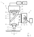
- FIG. 1 is a schematic view showing an entire configuration of an example of an embodiment embodying the present invention.
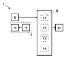
- FIG. 2 is a functional block diagram showing the connection of each device in an example of the embodiment embodying the present invention.
- the characteristic evaluation device 1 has the applied droplet LQ by capturing a three-dimensional shape change in the drying process with the passage of time of the droplet (hereinafter, applied droplet) LQ applied on the substrate W.
- the characteristic evaluation device 1 includes a light source unit 7, an image pickup unit 8, a computer unit 9, a display unit 10, and the like.
- the light source unit 7 irradiates light L1 of at least three types of wavelengths toward the coated droplet LQ coated on the substrate W.
- the light source unit 7 includes a lighting unit 70 and a lighting power supply 75.
- the illumination unit 70 emits light of at least three wavelengths necessary for capturing an interference color image.
- the lighting unit 70 includes a white lamp 70, a reflecting plate 71, and a three-wavelength band filter 72.
- the white lamp 70 emits light in a wide band (so-called broad wavelength band) including blue: 470 nm, green: 560 nm and red: 600 nm, and a halogen lamp can be specifically exemplified.
- the reflection plate 71 reflects visible light emitted from the white lamp 70 and increases the amount of light L1 emitted to the outside.
- the three-wavelength band-pass filter 72 passes at least three wavelength components (here, blue, green and red are exemplified) and attenuates the other wavelength components. It is. More specifically, the three-wavelength band-pass filter 72 is formed of a band pass filter in which a plurality of thin films are formed on the surface of a glass or quartz substrate.
- the illumination power supply 75 supplies the white lamp 70 of the illumination unit 70 with the power necessary for light emission.
- the image pickup unit 8 picks up the light L3 reflected by the application droplet LQ as an interference color image by the color camera 80 from above.
- the image pickup unit 8 includes a color camera 80 and a lens unit 81.
- the light L3 reflected by the application droplet LQ is the light reflected by the surface of the application droplet LQ (so-called surface reflection light) and the light L3 reflected at the interface between the application droplet LQ and the substrate W Light (so-called back surface reflected light) is combined (that is, interference light).
- the color camera 80 outputs a video signal (analog signal) and video data (digital signal) corresponding to a captured color image to the outside, and includes a color filter 85 and an imaging element 86.
- the lens unit 81 forms an image of the application droplet LQ on the imaging device 86 of the color camera 80.
- the lens unit 81 in the present embodiment also plays a role of irradiating the light emitted from the light source 7 toward the imaging target, and making the illumination light the same as the imaging optical axis (that is, the coaxial falling tilt method).
- the lens unit 81 includes a half mirror 82, an objective lens 83, and an imaging lens 84.
- the lens unit 81 reflects the light L1 emitted from the light source unit 7 by the half mirror 82 and irradiates it as the illumination light L2 to the measurement target area R, and of the light L3 reflected by the application droplet LQ,
- the light L 4 that has passed through the objective lens 83 and the half mirror 82 can be imaged on the imaging element 86 of the color camera 80 by the imaging lens 84.
- the computer unit 9 inputs and outputs signals and data, stores data, performs arithmetic processing on input or stored data, inputs and stores images, performs image processing on these images, determination processing based on the image processing, and image conversion Processing, determination results, and output of an image after image processing are performed.
- the computer unit 9 includes an input unit, an information recording unit, a numerical operation processing unit, an image processing unit, and an output unit. More specifically, the computer unit 9 is configured by a computer (hardware) having an image processing function and its execution program (software).
- the computer unit 9 further includes an information input device such as a keyboard, a mouse, and a track pad, and is connected to a display unit 10 described later.
- the computer unit 9 includes an image recording unit 11, a droplet shape measurement unit 12, a time-lapse droplet shape recording unit 13, and a characteristic evaluation unit 14.
- the image recording unit 11 records the interference color image captured by the image capturing unit 8.
- the image recording unit 11 is configured of an information recording unit of the computer unit 9 (for example, a magnetic recording medium such as a hard disk or a semiconductor memory).
- the droplet shape measurement unit 12 measures the three-dimensional shape of the coated droplet LQ using light interference method with a plurality of wavelengths. Specifically, the droplet shape measurement unit 12 measures the film thickness distribution of the application droplet LQ by measuring the film thickness of each point from the interference color image recorded in the image recording unit 11, and the three-dimensional shape To measure the The film thickness measurement method of each point is color separated for each light of at least three kinds of wavelengths from the color information of the point to calculate the brightness value, and the phase for each wavelength is calculated from the brightness value. A plurality of film thickness candidates are calculated from the phase, and a film thickness value is estimated from the calculated plurality of film thickness candidates. More specifically, the droplet shape measurement unit 12 is configured by an image processing unit or numerical operation processing unit (hardware) of the computer unit 9 and an execution program (software) thereof.
- the computer unit 9 performs predetermined image processing based on the execution program, or performs image recording
- the image is stored in the unit 11, the image is read out from the image recording unit 11, and the droplet shape measurement unit 12 performs predetermined image processing and numerical calculation processing to obtain the film thickness distribution of the applied droplet LQ.
- the calculation that is, measurement
- the three-dimensional shape of the application droplet LQ can be calculated (that is, measurement).
- the droplet shape measurement unit 12 performs the wavelength estimation process based on interference fringe model fitting as described in Patent Document 2 on each point in the image (that is, a plurality of wavelengths).
- the film thickness distribution is measured using the light interference method according to (1), and the three-dimensional shape of the coated droplet LQ is measured.
- the droplet shape measurement unit 12 emits illumination light including monochromatic light of a plurality of wavelengths to the transparent film to be measured, and is generated by the reflected light on the surface of the transparent film and the reflected light on the back surface Select one or more selected points from the interference color image, select an interference luminance signal of the wavelength number j corresponding to the point number i among the selected points of the n points, and select the wavelength ⁇ (j) of the wavelength number j It is assumed that the average brightness a (j) of wavelength number j, the interference modulation index b (j), and the film thickness t (i) of point number i are all or part of unknown parameters, and the rest are known parameters.
- processing for obtaining an unknown parameter that is, film thickness estimation calculation processing
- ⁇ (k, j) cos ⁇ 1 [ ⁇ g (k, j) / a (j) -1 ⁇ / b (j)]
- FIG. 3 is an image diagram showing an example of the interference color image input to the droplet shape measurement unit 12.
- FIG. 3 shows an interference color image of the application droplet LQ.
- image information originally includes color information, due to the restriction as an attached drawing, it is substituted by what is expressed in black and white shades (the same applies to the following).
- the temporal droplet shape recording unit 13 records the temporal droplet shape.
- the "time-dependent droplet shape” referred to here is a string obtained by linking the three-dimensional shape of the coated droplet LQ measured by the droplet shape measurement unit 12 and the time when the three-dimensional shape of the coated droplet LQ is measured. It is.
- the time-dependent droplet shape includes data (so-called, body) indicating the three-dimensional shape of the applied droplet LQ and time data (so-called, header) when the three-dimensional shape of the applied droplet LQ is measured. It has a linked data structure.
- the characteristic evaluation unit 14 evaluates the characteristic of the application droplet LQ based on the plurality of temporal droplet shapes having different measurement times recorded in the temporal droplet shape recording unit 13.
- the property evaluation unit 14 calculates the following items and the like based on the time-dependent droplet shape (that is, evaluates the characteristics of the coated droplet LQ).
- the solute diffusion constant D is a constant depending on the material of the coating liquid, and can be calculated from the molar volume of the solute in the droplet, the
- the display unit 10 is also called an information display or a display monitor, and when a video signal output from the computer unit 9 is input, characters, graphic information, and the like are displayed corresponding to the video signal. Specifically, the display unit 10 displays an image, information, etc. as described below. Among the interference color images recorded in the image recording unit 11, a selected interference color image. An image in which the film thickness distribution of the coated droplet LQ measured by the droplet shape measurement unit 12 is represented by a two-dimensional distribution.
- An image that three-dimensionally represents the film thickness distribution of the coated droplet LQ measured by the droplet shape measurement unit 12-The film thickness distribution of the coated droplet LQ recorded in the time-lapse droplet shape recording unit 13 is two-dimensional or three-dimensional Images of the original representation arranged in order of measurement time ⁇ Superimposition of cross-sectional profiles of the application droplet LQ at different measurement times ⁇ Characteristics of the application droplet LQ
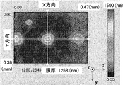
- FIG. 4 is an image diagram showing an example of an image in which the measurement result of the film thickness distribution is represented by a two-dimensional distribution.
- FIG. 5 is an image diagram showing an example of an image three-dimensionally expressing the measurement result of the film thickness distribution.
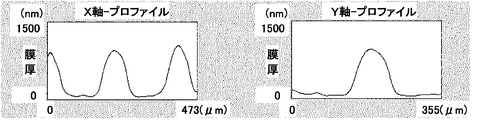
- FIG. 6 is an image diagram showing an example of a measurement result profile of film thickness distribution in the X direction and the Y direction.
- FIG. 7 is an image view showing an example of an interference color image and an X-direction profile of the film thickness distribution, which show a change with time.
- the images shown in FIG. 7 are the interference color image and the X direction profile image of the coated droplet LQ after 5 minutes, 9 minutes, 13 minutes, and 17 minutes after 5 minutes of discharging the coated droplet LQ. It is an arrangement of
- the characteristic evaluation device 1 can measure the three-dimensional shape of the coated droplet LQ at high speed and can accurately change the three-dimensional shape in the process of drying the coated droplet LQ because of such a configuration. It is possible to capture At this time, by irradiating light including three wavelengths of blue, green and red from the light source section 7, the film thickness distribution can be obtained even in a wide film thickness range of about 20 nm to 8 ⁇ m of the film thickness of the coated droplet LQ. It can be measured.
- the characteristic evaluation unit 13 may be configured to evaluate the characteristics of the coated droplet LQ at one time.
- the white lamp 70 constituting the light source unit 7 is not limited to the above-described halogen lamp, and may be a metal halide lamp, a xenon lamp, a mercury lamp, a white LED or the like.
- the three-wavelength band-pass filter 72 constituting the light source unit 7 is not limited to the configuration disposed between the white lamp 70 and the half mirror 82 as described above, but a half mirror between the objective lens 83 and the coated droplet LQ It may be arranged between the imaging lens 84 and the imaging lens 84, between the imaging lens 84 and the imaging camera 80, or the like.
- the light source unit 7 is not limited to the configuration including the white lamp 70, the reflection plate 71, and the three-wavelength band filter 72 as described above, but the LED emitting blue, the LED emitting green, and the red It is good also as composition provided with the light emission unit provided with LED.
- one or more LEDs of each color are provided, and the illumination power supply is configured to supply a predetermined DC voltage and current to each LED.
- a laser diode emitting light of each color or a laser diode emitting light of three wavelengths simultaneously and a power supply for driving the laser diode may be provided.
- the structure which irradiates the light of three types of wavelength of blue: 470 nm, green: 560 nm, and red: 600 nm as the light source part 7 was illustrated.
- the light source unit according to the present invention is not limited to such a configuration, and part or all of the light source unit may be replaced with light of another wavelength.
- the light of the other wavelength irradiated from the light source part near infrared light, orange light, blue green light and the like can be exemplified.
- the wavelength of the light irradiated from the light source part 7 is good also as four types in all, and good also as a kind beyond it.
Landscapes
- Physics & Mathematics (AREA)
- General Physics & Mathematics (AREA)
- Analytical Chemistry (AREA)
- Biochemistry (AREA)
- Spectroscopy & Molecular Physics (AREA)
- Health & Medical Sciences (AREA)
- Life Sciences & Earth Sciences (AREA)
- Chemical & Material Sciences (AREA)
- Mathematical Physics (AREA)
- Theoretical Computer Science (AREA)
- General Health & Medical Sciences (AREA)
- Engineering & Computer Science (AREA)
- Immunology (AREA)
- Pathology (AREA)
- Length Measuring Devices By Optical Means (AREA)
- Investigating Or Analysing Materials By Optical Means (AREA)
Abstract
乾燥過程における塗布液滴の経時三次元形状変化を正確に捉え、当該塗布液滴が有する特性を評価する特性評価装置を提供すること。 具体的には、塗布液滴の時間経過に伴う乾燥過程における三次元形状変化を捉えることで当該塗布液滴が有する特性を評価する特性評価装置であって、 複数波長による光干渉法を用いて当該塗布液滴の三次元形状を測定する液滴形状測定部と、 液滴形状測定部で測定した塗布液滴の三次元形状と、当該塗布液滴の三次元形状を測定した時刻とを紐付けた、経時液滴形状を記録する経時液滴形状記録部と、 経時液滴形状記録部に記録された、測定時刻の異なる複数の経時液滴形状に基づいて、当該塗布液滴が有する特性を評価する特性評価部とを備えた、塗布液滴の特性評価装置。
Description
本発明は、インクジェットやディスペンサ等で塗布された液滴(つまり、塗布液滴)の時間経過に伴う乾燥過程における三次元形状変化を捉えることで当該塗布液滴が有する特性を評価する特性評価装置に関するものである。
液晶ディスプレイのカラーフィルタやプリンタブルエレクトロニクスの配線などは、インクジェットやディスペンサ等を用いて所望のパターンで塗布された液滴を乾燥させることで、所定パターンの塗布皮膜や配線などが形成されている。
そして、これら塗布液滴を乾燥させた後の塗布皮膜や配線の膜厚均一化や側面垂直性の向上が求められている。そのためには、塗布液滴の乾燥過程における動的な三次元形状変化を正確に捉え、塗布条件や塗布材料に反映することが重要である。
北川、大槻,「干渉色画像解析による透明膜の広視野膜厚分布測定装置の開発」,精密工学会誌,2013年11月,第79巻,第11号,1078-1082頁
レーザビームをスキャンさせて凹凸形状を測る技術では、液滴の乾燥速度が速い場合にはそのスキャン中に液滴形状が変化してしまい、塗布液滴の形状を正確に測定できない。
一方、塗布液滴をエリアセンサカメラで上方から平面視して撮像する技術では、平面視したときの形状(円形か楕円かなど)や寸法(直径など)は把握できるが、垂直方向の膜厚分布が分からない。
一方、特許文献1に示す様な位相測定法では、干渉縞による位相接続で膜厚を算出するため、液滴輪郭部などの急峻な膜厚変化部分は干渉縞が過密になり正しく位相を測定できない。また、ピエゾ鏡を移動させながら位相測定をしているため、液滴の乾燥速度が速い場合にはその移動時間中に液滴形状が変化してしまい、塗布液滴の形状を正確に測定できない。
一方、特許文献2では、フィルム製造プロセスにおいて連続走行するフィルムシートの膜厚をオンライン計測することに適用可能な旨が記載されており、非特許文献1では、シリコンウエハ上のシリコン酸化膜の膜厚、ニュートンリング板の空気間隙、シャボン膜の膜厚を測定できる旨が記載されているが、塗布液滴の乾燥過程における動的な三次元形状変化を捉え、当該塗布液滴が有する特性が評価できることまでは言及されていない。
そこで本発明は、乾燥過程における塗布液滴の経時三次元形状変化を正確に捉え、当該塗布液滴が有する特性を評価する特性評価装置を提供することを目的とする。
以上の課題を解決するために、本発明に係る一態様は、
塗布液滴の時間経過に伴う乾燥過程における三次元形状変化を捉えることで当該塗布液滴が有する特性を評価する特性評価装置であって、
複数波長による光干渉法を用いて当該塗布液滴の三次元形状を測定する液滴形状測定部と、
液滴形状測定部で測定した塗布液滴の三次元形状と、当該塗布液滴の三次元形状を測定した時刻とを紐付けた、経時液滴形状を記録する経時液滴形状記録部と、
経時液滴形状記録部に記録された、測定時刻の異なる複数の経時液滴形状に基づいて、当該塗布液滴が有する特性を評価する特性評価部とを備えた、
塗布液滴の特性評価装置である。
塗布液滴の時間経過に伴う乾燥過程における三次元形状変化を捉えることで当該塗布液滴が有する特性を評価する特性評価装置であって、
複数波長による光干渉法を用いて当該塗布液滴の三次元形状を測定する液滴形状測定部と、
液滴形状測定部で測定した塗布液滴の三次元形状と、当該塗布液滴の三次元形状を測定した時刻とを紐付けた、経時液滴形状を記録する経時液滴形状記録部と、
経時液滴形状記録部に記録された、測定時刻の異なる複数の経時液滴形状に基づいて、当該塗布液滴が有する特性を評価する特性評価部とを備えた、
塗布液滴の特性評価装置である。
このような態様によれば、高速で塗布液滴の三次元形状の測定ができるため、当該塗布液滴の乾燥過程における三次元形状の変化を正確に捉えることが可能となる。そのうえ、広域モデル適合法により、塗布液滴を撮像した干渉色画像から校正を行う(いわゆる、セルフキャリブレーションを行う)ため、各色情報と膜厚値との関係づけの校正が不要であり、青・緑・赤色の3波長を用いれば、20nmないし8μm程度の幅広い膜厚レンジで、塗布液滴の三次元形状の測定が可能となる。
乾燥過程における塗布液滴の経時三次元形状変化を正確に捉え、当該塗布液滴が有する特性を評価することができる。
以下に、本発明を実施するための形態について、図を用いながら説明する。なお各図では、水平方向をx方向、y方向と表現し、xy平面に垂直な方向(つまり、重力方向)をz方向と表現する。また、重力に逆らう方向を上、重力がはたらく方向を下と表現する。
図1は、本発明を具現化する形態の一例の全体構成を示す概略図である。
図2は、本発明を具現化する形態の一例における各機器のつながりを示す機能ブロック図である。
図2は、本発明を具現化する形態の一例における各機器のつながりを示す機能ブロック図である。
本発明に係る特性評価装置1は、基板W上に塗布された液滴(以下、塗布液滴)LQの時間経過に伴う乾燥過程における三次元形状変化を捉えることで当該塗布液滴LQが有する特性を評価するものである。
具体的には、特性評価装置1は、光源部7、画像撮像部8、コンピュータ部9、表示部10等を備えて構成されている。
具体的には、特性評価装置1は、光源部7、画像撮像部8、コンピュータ部9、表示部10等を備えて構成されている。
光源部7は、基板W上に塗布された塗布液滴LQに向けて少なくとも3種類の波長の光L1を照射するものである。具体的には、光源部7は、照明ユニット70と、照明用電源75を備えている。
照明ユニット70は、干渉色画像の撮像に必要な、少なくとも3種類の波長の光を発するものである。具体的には、照明ユニット70は、白色ランプ70と、反射板71と、3波長帯域フィルタ72を備えている。白色ランプ70は、青色:470nm、緑色:560nm、赤色:600nmを含む広い帯域(いわゆる、ブロードな波長帯域)の光を放出するものであり、具体的にはハロゲンランプが例示できる。反射板71は、白色ランプ70から放出された可視光を反射し、外部に照射する光L1の量を増やすものである。3波長帯域フィルタ72は、白色ランプ70から放出された光のうち、少なくとも3種類の波長成分(ここでは、青色・緑色・赤色を例示する)を通過させ、それ以外の波長成分を減衰させるものである。より具体的には、3波長帯域フィルタ72は、ガラスや石英基板の表面に複数の薄膜が形成されたバンドパスフィルターで構成されている。
照明用電源75は、照明ユニット70の白色ランプ70に対して、発光に必要な電力を供給するものである。
画像撮像部8は、塗布液滴LQで反射された光L3を、上方からカラーカメラ80にて干渉色画像として撮像するものである。具体的には、画像撮像部8は、カラーカメラ80と、レンズユニット81を備えている。なお、ここで言う、塗布液滴LQで反射された光L3とは、塗布液滴LQの表面で反射した光(いわゆる、表面反射光)と、塗布液滴LQと基板Wとの界面で反射した光(いわゆる、裏面反射光)とが合成されたもの(つまり、干渉光)である。
カラーカメラ80は、撮像されたカラー画像に対応した映像信号(アナログ信号)や映像データ(デジタル信号)を外部に出力するものであり、カラーフィルタ85と、撮像素子86を備えている。
レンズユニット81は、塗布液滴LQの像を、カラーカメラ80の撮像素子86に結像させるものである。また、本実施例におけるレンズユニット81は、光源7から照射された光を、撮像対象に向けて照射する役割も併せ持ち、照明光を撮像光軸と同じ(つまり、同軸落斜方式)にすることができる。具体的には、レンズユニット81は、ハーフミラー82、対物レンズ83、結像レンズ84を備えている。そのため、レンズユニット81は、光源部7から照射された光L1を、ハーフミラー82で反射させて照明光L2として測定対象領域Rに照射し、塗布液滴LQで反射された光L3のうち、対物レンズ83とハーフミラー82を通過した光L4を結像レンズ84にてカラーカメラ80の撮像素子86に結像させることができる。
コンピュータ部9は、信号やデータの入力や出力、データの記憶、入力または記憶されたデータに対する演算処理のほか、画像の入力や記憶、これら画像に対する画像処理、画像処理に基づく判定処理や画像変換処理、判定結果や画像処理後の画像の出力などを行うものである。具体的には、コンピュータ部9は、入力部、情報記録部、数値演算処理部、画像処理部、出力部を備えている。より具体的には、コンピュータ部9は、画像処理機能を備えたコンピュータ(ハードウェア)とその実行プログラム(ソフトウェア)により構成されている。また、コンピュータ部9は、キーボードやマウス、トラックパッドなどの情報入力デバイスを備え、後述する表示部10と接続されている。
コンピュータ部9は、画像記録部11、液滴形状測定部12、経時液滴形状記録部13、特性評価部14を備えている。
画像記録部11は、画像撮像部8で撮像された干渉色画像を記録するものである。具体的には、画像記録部11は、コンピュータ部9の情報記録部(例えば、ハードディスクなどの磁気記録媒体や、半導体メモリーなど)で構成されている。
液滴形状測定部12は、複数波長による光干渉法を用いて塗布液滴LQの三次元形状を測定するものである。具体的には、液滴形状測定部12は、画像記録部11に記録された干渉色画像より、各点の膜厚を測定して塗布液滴LQの膜厚分布を測定し、三次元形状を測定するものである。各点の膜厚測定方法は、その点の色情報から少なくとも3種類の波長の光毎に色分離して輝度値を算出し、当該輝度値から波長毎の位相を算出し、当該波長毎の位相から複数の膜厚候補を算出し、当該算出された複数の膜厚候補から膜厚値を推定するものである。より具体的には、液滴形状測定部12は、コンピュータ部9の画像処理部や数値演算処理部(ハードウェア)と、その実行プログラム(ソフトウェア)で構成されている。
そのため、コンピュータ部9は、画像撮像部8から出力された映像信号(アナログ信号)や映像データ(デジタル信号)が入力されると、実行プログラムに基づいて、所定の画像処理を行ったり、画像記録部11に画像を保存したり、画像記録部11から画像を読み出したり、液滴形状測定部12にて所定の画像処理や数値演算処理をしたりして、塗布液滴LQの膜厚分布を算出(つまり、測定)し、塗布液滴LQの三次元形状を算出(つまり、測定)することができる。
具体的には、液滴形状測定部12は、特許文献2に記載されているような干渉縞モデル適合による波長推定処理を、画像内の各点に対して行うことで、(つまり、複数波長による光干渉法を用いて)膜厚分布を測定し、塗布液滴LQの三次元形状を測定するものである。
より具体的には、液滴形状測定部12は、複数の波長の単色光を含む照明光を測定対象である透明膜に照射し、透明膜の表面の反射光と裏面の反射光により生成される干渉色画像から1点以上の選択点をn点選択し、n点の選択点の内の点番号iに対応する波長番号jの干渉輝度信号に、波長番号jの波長λ(j)を既知とし、波長番号jの平均輝度a(j)、干渉変調度b(j)、および点番号iの膜厚t(i)のすべて、あるいは、一部を未知パラメータとし、残りを既知パラメータとして、点番号iに対応する波長番号jの輝度g(i,j)が、次式
g(i,j)=a(j)[1+b(j)×cos{4πt(i)/λ(j)}]
で表される干渉縞モデルを適合することにより、未知パラメータを求める処理(つまり、膜厚推定演算処理)を行う。
g(i,j)=a(j)[1+b(j)×cos{4πt(i)/λ(j)}]
で表される干渉縞モデルを適合することにより、未知パラメータを求める処理(つまり、膜厚推定演算処理)を行う。
さらに、干渉色画像内の任意の点番号kに関し、先に得られて既知の波長番号jの平均輝度a(j)および干渉変調度b(j)と、点番号kの各波長の輝度g(k,j)とから、点番号kにおける波長番号jの位相φ(k,j)を、次式
φ(k,j)=cos-1[{g(k,j)/a(j)-1}/b(j)]
により求め、得られた当該波長毎の位相から、当該波長毎に複数の膜厚候補を求め、当該波長どうしの複数の膜厚候補を突き合わせて最も合致する膜厚t(k)を求める処理(つまり、膜厚推定演算処理)を行う。
φ(k,j)=cos-1[{g(k,j)/a(j)-1}/b(j)]
により求め、得られた当該波長毎の位相から、当該波長毎に複数の膜厚候補を求め、当該波長どうしの複数の膜厚候補を突き合わせて最も合致する膜厚t(k)を求める処理(つまり、膜厚推定演算処理)を行う。
図3は、液滴形状測定部12に入力される干渉色画像の一例を示す画像図である。図3には、塗布液滴LQの干渉色画像が示されている。なお画像図には、本来カラー情報も含まれるが、添付図面としての制約上、白黒の濃淡にて表現したもので代用する(以下同様)。
経時液滴形状記録部13は、経時液滴形状を記録するものである。ここで言う「経時液滴形状」とは、液滴形状測定部12で測定した塗布液滴LQの三次元形状と、当該塗布液滴LQの三次元形状を測定した時刻とを紐付けたものである。
具体的には、経時液滴形状は、塗布液滴LQの三次元形状を示すデータ(いわゆる、ボディ)と、当該塗布液滴LQの三次元形状を測定した時刻データ(いわゆる、ヘッダ)とが紐付けされたデータ構造をしている。
特性評価部14は、経時液滴形状記録部13に記録された、測定時刻の異なる複数の前記経時液滴形状に基づいて、塗布液滴LQが有する特性を評価するものである。
具体的には、特性評価部14は、経時液滴形状に基づいて下述の項目等を算出(つまり、塗布液滴LQが有する特性を評価)する。
・測定時刻T1,T2における、塗布液滴LQの体積V1,V2
・測定時刻T1,T2における、塗布液滴LQの表面積S1,S2
・測定時刻T1,T2間の蒸発量:V2-V1
・単位時間当たりの蒸発量:例えば、(V2-V1)/(T2-T1)
・単位時間当たりで単位面積当たりの蒸発量(すなわち、蒸発速度J)
:例えばJ=(V2-V1)/(T2-T1)/{(S1+S2)/2}
・ペクレ数:塗布液滴LQの半径R×蒸発速度J/溶質拡散定数D
なお、溶質拡散定数Dは、塗布液の材料に依る定数であり、液滴内溶質のモル体積、液滴内溶媒の粘度、分子量、会合度から算出できる。
・測定時刻T1,T2における、塗布液滴LQの体積V1,V2
・測定時刻T1,T2における、塗布液滴LQの表面積S1,S2
・測定時刻T1,T2間の蒸発量:V2-V1
・単位時間当たりの蒸発量:例えば、(V2-V1)/(T2-T1)
・単位時間当たりで単位面積当たりの蒸発量(すなわち、蒸発速度J)
:例えばJ=(V2-V1)/(T2-T1)/{(S1+S2)/2}
・ペクレ数:塗布液滴LQの半径R×蒸発速度J/溶質拡散定数D
なお、溶質拡散定数Dは、塗布液の材料に依る定数であり、液滴内溶質のモル体積、液滴内溶媒の粘度、分子量、会合度から算出できる。
表示部10は、インフォメーションディスプレイ、表示モニタとも呼ばれ、コンピュータ部9から出力された映像信号が入力されると、映像信号に対応して文字や図形情報などが表示されるものである。具体的には、表示部10は、下述の様な画像や情報等を表示する。
・画像記録部11に記録された干渉色画像のうち、選択された干渉色画像
・液滴形状測定部12で測定された塗布液滴LQの膜厚分布を二次元分布で表した画像
・液滴形状測定部12で測定された塗布液滴LQの膜厚分布を三次元的に表した画像
・経時液滴形状記録部13に記録された塗布液滴LQの膜厚分布を二次元または三次元的に表した画像を、測定時刻順に並べたもの
・異なる測定時刻の塗布液滴LQの断面プロファイルを重ね合わせたもの
・塗布液滴LQが有する特性
・画像記録部11に記録された干渉色画像のうち、選択された干渉色画像
・液滴形状測定部12で測定された塗布液滴LQの膜厚分布を二次元分布で表した画像
・液滴形状測定部12で測定された塗布液滴LQの膜厚分布を三次元的に表した画像
・経時液滴形状記録部13に記録された塗布液滴LQの膜厚分布を二次元または三次元的に表した画像を、測定時刻順に並べたもの
・異なる測定時刻の塗布液滴LQの断面プロファイルを重ね合わせたもの
・塗布液滴LQが有する特性
図4は、膜厚分布の測定結果を二次元分布で表した画像の一例を示す画像図である。
図5は、膜厚分布の測定結果を三次元的に表した画像の一例を示す画像図である。
図6は、X方向およびY方向の膜厚分布の測定結果プロファイルの一例を示す画像図である。
図7は、干渉色画像および膜厚分布のX方向プロファイルの、経時変化を表した画像の一例を示す画像図である。図7に示す画像は、塗布液滴LQを吐出させて5分経過後、9分経過後、13分経過後、17分経過後における、干渉色画像ならびに、塗布液滴LQのX方向プロファイル画像を並べたものである。
本発明に係る特性評価装置1は、この様な構成をしているため、高速で塗布液滴LQの三次元形状の測定ができ、塗布液滴LQの乾燥過程における三次元形状の変化を正確に捉えるが可能となる。このとき、光源部7から青色・緑色・赤色の3種類の波長を含んだ光を照射することで、塗布液滴LQの膜厚が20nmないし8μm程度の幅広い膜厚レンジでも、膜厚分布を測定することができる。
[別の形態]
なお上述では、塗布液滴LQが1つの場合について詳細な説明を行ったが、複数の塗布液滴LQを1つの観察視野内に収め、これら塗布液滴LQについて一度に膜厚分布を測定し、特性評価部13は、これら塗布液滴LQが有する特性を一度に評価する構成であっても良い。
なお上述では、塗布液滴LQが1つの場合について詳細な説明を行ったが、複数の塗布液滴LQを1つの観察視野内に収め、これら塗布液滴LQについて一度に膜厚分布を測定し、特性評価部13は、これら塗布液滴LQが有する特性を一度に評価する構成であっても良い。
[光源部の変形例]
光源部7を構成する白色ランプ70は、上述のハロゲンランプに限らず、メタルハライドランプ、キセノンランプ、水銀ランプ、白色LEDなどで構成しても良い。
光源部7を構成する白色ランプ70は、上述のハロゲンランプに限らず、メタルハライドランプ、キセノンランプ、水銀ランプ、白色LEDなどで構成しても良い。
また、光源部7を構成する3波長帯域フィルタ72は、上述のような白色ランプ70とハーフミラー82の間に配置された構成に限らず、対物レンズ83と塗布液滴LQの間、ハーフミラー82と結像レンズ84の間、結像レンズ84と撮像カメラ80の間などに配置した構成としても良い。
また光源部7は、上述のような白色ランプ70と、反射板71と、3波長帯域フィルタ72を備えた構成に限らず、青色に発光するLEDと、緑色に発光するLEDと、赤色に発光するLEDとを備えた発光ユニットを備えた構成としても良い。この場合、各色のLEDは、1個ずつないし複数備えた構成とし、照明用電源は、各LEDに所定の直流電圧と電流を供給する構成としておく。或いは、各色で発光するLEDに代えて、各色で発光するレーザダイオードまたは3波長が同時発光するレーザダイオードと、そのレーザダイオードを駆動させる電源を備えた構成としても良い。
また上述では、光源部7として、青色:470nm、緑色:560nm、赤色:600nmの3種類の波長の光を照射する構成を例示した。しかし、本発明に係る光源部は、このような構成に限定されず、一部又は全部を他の波長の光に代えた構成としても良い。この場合、光源部から照射される他の波長の光としては、近赤外線の光、橙色の光、青緑色の光などが例示できる。また、光源部7から照射される光の波長は、全部で4種類としても良いし、それ以上の種類としても良い。
1 特性評価装置
7 光源部
8 画像撮像部
9 コンピュータ部
10 表示部
11 画像記録部
12 液滴形状測定部
13 経時液滴形状記録部
14 特性評価部
70 白色ランプ
72 3波長帯域フィルタ
75 照明用電源
80 撮像カメラ
81 レンズユニット
82 ハーフミラー
83 対物レンズ
84 結像レンズ
85 カラーフィルタ
86 撮像素子
F 膜厚の測定対象領域
L1 光源部から照射された光
L2 膜厚の測定対象領域に照射された光
L3 膜厚の測定対象領域から反射された光(干渉光)
L4 ハーフミラーを通過した光(撮像される干渉光)
W 基板
7 光源部
8 画像撮像部
9 コンピュータ部
10 表示部
11 画像記録部
12 液滴形状測定部
13 経時液滴形状記録部
14 特性評価部
70 白色ランプ
72 3波長帯域フィルタ
75 照明用電源
80 撮像カメラ
81 レンズユニット
82 ハーフミラー
83 対物レンズ
84 結像レンズ
85 カラーフィルタ
86 撮像素子
F 膜厚の測定対象領域
L1 光源部から照射された光
L2 膜厚の測定対象領域に照射された光
L3 膜厚の測定対象領域から反射された光(干渉光)
L4 ハーフミラーを通過した光(撮像される干渉光)
W 基板
Claims (3)
- 塗布液滴の時間経過に伴う乾燥過程における三次元形状変化を捉えることで当該塗布液滴が有する特性を評価する特性評価装置であって、
複数波長による光干渉法を用いて前記塗布液滴の三次元形状を測定する液滴形状測定部と、
前記液滴形状測定部で測定した前記塗布液滴の三次元形状と、当該塗布液滴の三次元形状を測定した時刻とを紐付けた、経時液滴形状を記録する経時液滴形状記録部と、
前記経時液滴形状記録部に記録された、前記測定時刻の異なる複数の前記経時液滴形状に基づいて、当該塗布液滴が有する特性を評価する特性評価部とを備えた、
塗布液滴の特性評価装置。 - 前記液滴形状測定部は、複数の塗布液滴について一度に膜厚分布を測定し、
前記特性評価部は、これら塗布液滴が有する特性を一度に評価する
ことを特徴とする、請求項1に記載の塗布液滴の特性評価装置。 - 前記塗布液滴が有する特性の評価項目として、蒸発速度、ペクレ数のうち少なくとも1つを算出する
ことを特徴とする、請求項1又は請求項2に記載の塗布液滴の特性評価装置。
Applications Claiming Priority (2)
| Application Number | Priority Date | Filing Date | Title |
|---|---|---|---|
| JP2017-184670 | 2017-09-26 | ||
| JP2017184670A JP2019060683A (ja) | 2017-09-26 | 2017-09-26 | 塗布液滴の特性評価装置 |
Publications (1)
| Publication Number | Publication Date |
|---|---|
| WO2019064692A1 true WO2019064692A1 (ja) | 2019-04-04 |
Family
ID=65903366
Family Applications (1)
| Application Number | Title | Priority Date | Filing Date |
|---|---|---|---|
| PCT/JP2018/020265 Ceased WO2019064692A1 (ja) | 2017-09-26 | 2018-05-28 | 塗布液滴の特性評価装置 |
Country Status (2)
| Country | Link |
|---|---|
| JP (1) | JP2019060683A (ja) |
| WO (1) | WO2019064692A1 (ja) |
Cited By (1)
| Publication number | Priority date | Publication date | Assignee | Title |
|---|---|---|---|---|
| JP2022166815A (ja) * | 2021-04-21 | 2022-11-02 | 株式会社村田製作所 | インクジェット印刷装置の評価装置、および、インクジェット印刷装置 |
Citations (8)
| Publication number | Priority date | Publication date | Assignee | Title |
|---|---|---|---|---|
| JP2008046110A (ja) * | 2006-07-20 | 2008-02-28 | Canon Inc | 液滴の形状計測方法及び装置 |
| JP2008209404A (ja) * | 2007-01-31 | 2008-09-11 | Tokyo Institute Of Technology | 複数波長による表面形状の測定方法およびこれを用いた装置 |
| JP2010139294A (ja) * | 2008-12-10 | 2010-06-24 | Seiko Epson Corp | 着弾ドットの体積測定方法 |
| JP2014124542A (ja) * | 2012-12-25 | 2014-07-07 | Fujitsu Ltd | 接着剤の塗布方法及び装置 |
| JP2014211395A (ja) * | 2013-04-19 | 2014-11-13 | 国立大学法人島根大学 | 塗料乾燥に伴う溶剤の密度推定法 |
| JP2016024089A (ja) * | 2014-07-22 | 2016-02-08 | 株式会社リコー | 液体状態変化測定装置及び液体状態変化測定方法 |
| US20160123725A1 (en) * | 2013-05-31 | 2016-05-05 | University Of North Carolina At Charlotte | Methods of determining the shape of a sessile drop |
| WO2017122633A1 (ja) * | 2016-01-13 | 2017-07-20 | Ntn株式会社 | 微小突起の体積測定方法および液状材料の塗布方法 |
-
2017
- 2017-09-26 JP JP2017184670A patent/JP2019060683A/ja active Pending
-
2018
- 2018-05-28 WO PCT/JP2018/020265 patent/WO2019064692A1/ja not_active Ceased
Patent Citations (8)
| Publication number | Priority date | Publication date | Assignee | Title |
|---|---|---|---|---|
| JP2008046110A (ja) * | 2006-07-20 | 2008-02-28 | Canon Inc | 液滴の形状計測方法及び装置 |
| JP2008209404A (ja) * | 2007-01-31 | 2008-09-11 | Tokyo Institute Of Technology | 複数波長による表面形状の測定方法およびこれを用いた装置 |
| JP2010139294A (ja) * | 2008-12-10 | 2010-06-24 | Seiko Epson Corp | 着弾ドットの体積測定方法 |
| JP2014124542A (ja) * | 2012-12-25 | 2014-07-07 | Fujitsu Ltd | 接着剤の塗布方法及び装置 |
| JP2014211395A (ja) * | 2013-04-19 | 2014-11-13 | 国立大学法人島根大学 | 塗料乾燥に伴う溶剤の密度推定法 |
| US20160123725A1 (en) * | 2013-05-31 | 2016-05-05 | University Of North Carolina At Charlotte | Methods of determining the shape of a sessile drop |
| JP2016024089A (ja) * | 2014-07-22 | 2016-02-08 | 株式会社リコー | 液体状態変化測定装置及び液体状態変化測定方法 |
| WO2017122633A1 (ja) * | 2016-01-13 | 2017-07-20 | Ntn株式会社 | 微小突起の体積測定方法および液状材料の塗布方法 |
Cited By (2)
| Publication number | Priority date | Publication date | Assignee | Title |
|---|---|---|---|---|
| JP2022166815A (ja) * | 2021-04-21 | 2022-11-02 | 株式会社村田製作所 | インクジェット印刷装置の評価装置、および、インクジェット印刷装置 |
| JP7567837B2 (ja) | 2021-04-21 | 2024-10-16 | 株式会社村田製作所 | インクジェット印刷装置の評価装置、および、インクジェット印刷装置 |
Also Published As
| Publication number | Publication date |
|---|---|
| JP2019060683A (ja) | 2019-04-18 |
Similar Documents
| Publication | Publication Date | Title |
|---|---|---|
| JP4242767B2 (ja) | 2次元型検出器を用いた薄膜特性測定装置及びその測定方法 | |
| KR100415123B1 (ko) | 표면간거리의광학적측정방법및장치 | |
| KR20030025891A (ko) | 다층박막의 두께형상과 굴절률분포를 2차원형반사광도계의 원리를 이용하여 측정하는 장치와 그 측정방법 | |
| TWI426227B (zh) | 移動樣品之形貌的量測方法及其裝置 | |
| CN102472608A (zh) | 干涉显微镜和测定装置 | |
| KR20170053707A (ko) | 금속체의 형상 검사 장치 및 금속체의 형상 검사 방법 | |
| TWI567364B (zh) | 結構光產生裝置、量測系統及其方法 | |
| JP3511097B2 (ja) | 光干渉を用いた形状測定方法および形状測定装置 | |
| CN113281343A (zh) | 一种对多层透明材料进行缺陷检测的系统及方法 | |
| KR100785802B1 (ko) | 입체 형상 측정장치 | |
| JP2010060385A (ja) | 液膜厚の測定装置及び測定方法 | |
| JP5514641B2 (ja) | レーザー干渉バンプ測定器 | |
| JP5124485B2 (ja) | 光学表面センサー | |
| JP7370326B2 (ja) | 大視野3d分光顕微鏡法 | |
| JP2007538238A (ja) | デバイス上の局所構造体を測定する方法 | |
| JPH1183457A (ja) | スペクトル干渉顕微鏡及び該顕微鏡を用いた表面形状測定方法 | |
| WO2019064692A1 (ja) | 塗布液滴の特性評価装置 | |
| JP6207383B2 (ja) | 屈折率分布計測方法、屈折率分布計測装置、及び光学素子の製造方法 | |
| JP2000035315A (ja) | 透明材料の厚さを測定するための方法及び装置 | |
| JP2018004442A (ja) | 透明板の形状測定方法および形状測定装置 | |
| JPH09133517A (ja) | 分布測定装置 | |
| JP2008046110A (ja) | 液滴の形状計測方法及び装置 | |
| JP2010503832A (ja) | 三次元の流れ測定装置及び測定方法 | |
| JP3939028B2 (ja) | 斜入射干渉計 | |
| JP5239049B2 (ja) | 粗さ測定方法及び粗さ測定装置 |
Legal Events
| Date | Code | Title | Description |
|---|---|---|---|
| 121 | Ep: the epo has been informed by wipo that ep was designated in this application |
Ref document number: 18863003 Country of ref document: EP Kind code of ref document: A1 |
|
| NENP | Non-entry into the national phase |
Ref country code: DE |
|
| 122 | Ep: pct application non-entry in european phase |
Ref document number: 18863003 Country of ref document: EP Kind code of ref document: A1 |