WO2019064448A1 - 部品把持具 - Google Patents
部品把持具 Download PDFInfo
- Publication number
- WO2019064448A1 WO2019064448A1 PCT/JP2017/035280 JP2017035280W WO2019064448A1 WO 2019064448 A1 WO2019064448 A1 WO 2019064448A1 JP 2017035280 W JP2017035280 W JP 2017035280W WO 2019064448 A1 WO2019064448 A1 WO 2019064448A1
- Authority
- WO
- WIPO (PCT)
- Prior art keywords
- pair
- claws
- component
- pins
- contact
- Prior art date
Links
Images


Classifications
-
- B—PERFORMING OPERATIONS; TRANSPORTING
- B23—MACHINE TOOLS; METAL-WORKING NOT OTHERWISE PROVIDED FOR
- B23Q—DETAILS, COMPONENTS, OR ACCESSORIES FOR MACHINE TOOLS, e.g. ARRANGEMENTS FOR COPYING OR CONTROLLING; MACHINE TOOLS IN GENERAL CHARACTERISED BY THE CONSTRUCTION OF PARTICULAR DETAILS OR COMPONENTS; COMBINATIONS OR ASSOCIATIONS OF METAL-WORKING MACHINES, NOT DIRECTED TO A PARTICULAR RESULT
- B23Q7/00—Arrangements for handling work specially combined with or arranged in, or specially adapted for use in connection with, machine tools, e.g. for conveying, loading, positioning, discharging, sorting
- B23Q7/04—Arrangements for handling work specially combined with or arranged in, or specially adapted for use in connection with, machine tools, e.g. for conveying, loading, positioning, discharging, sorting by means of grippers
-
- H—ELECTRICITY
- H01—ELECTRIC ELEMENTS
- H01R—ELECTRICALLY-CONDUCTIVE CONNECTIONS; STRUCTURAL ASSOCIATIONS OF A PLURALITY OF MUTUALLY-INSULATED ELECTRICAL CONNECTING ELEMENTS; COUPLING DEVICES; CURRENT COLLECTORS
- H01R43/00—Apparatus or processes specially adapted for manufacturing, assembling, maintaining, or repairing of line connectors or current collectors or for joining electric conductors
- H01R43/20—Apparatus or processes specially adapted for manufacturing, assembling, maintaining, or repairing of line connectors or current collectors or for joining electric conductors for assembling or disassembling contact members with insulating base, case or sleeve
- H01R43/205—Apparatus or processes specially adapted for manufacturing, assembling, maintaining, or repairing of line connectors or current collectors or for joining electric conductors for assembling or disassembling contact members with insulating base, case or sleeve with a panel or printed circuit board
-
- H—ELECTRICITY
- H05—ELECTRIC TECHNIQUES NOT OTHERWISE PROVIDED FOR
- H05K—PRINTED CIRCUITS; CASINGS OR CONSTRUCTIONAL DETAILS OF ELECTRIC APPARATUS; MANUFACTURE OF ASSEMBLAGES OF ELECTRICAL COMPONENTS
- H05K13/00—Apparatus or processes specially adapted for manufacturing or adjusting assemblages of electric components
- H05K13/04—Mounting of components, e.g. of leadless components
- H05K13/0404—Pick-and-place heads or apparatus, e.g. with jaws
- H05K13/0408—Incorporating a pick-up tool
-
- H—ELECTRICITY
- H05—ELECTRIC TECHNIQUES NOT OTHERWISE PROVIDED FOR
- H05K—PRINTED CIRCUITS; CASINGS OR CONSTRUCTIONAL DETAILS OF ELECTRIC APPARATUS; MANUFACTURE OF ASSEMBLAGES OF ELECTRICAL COMPONENTS
- H05K13/00—Apparatus or processes specially adapted for manufacturing or adjusting assemblages of electric components
- H05K13/04—Mounting of components, e.g. of leadless components
- H05K13/0417—Feeding with belts or tapes
- H05K13/0419—Feeding with belts or tapes tape feeders
-
- H—ELECTRICITY
- H05—ELECTRIC TECHNIQUES NOT OTHERWISE PROVIDED FOR
- H05K—PRINTED CIRCUITS; CASINGS OR CONSTRUCTIONAL DETAILS OF ELECTRIC APPARATUS; MANUFACTURE OF ASSEMBLAGES OF ELECTRICAL COMPONENTS
- H05K13/00—Apparatus or processes specially adapted for manufacturing or adjusting assemblages of electric components
- H05K13/04—Mounting of components, e.g. of leadless components
- H05K13/0417—Feeding with belts or tapes
- H05K13/0426—Feeding with belts or tapes for components being oppositely extending terminal leads
Definitions
- the present invention relates to a component gripping tool that grips an electronic component by the approach of a pair of claws.
- Some component gripping tools grip electronic components by the approach of a pair of claws, as described in the following patent documents.
- the present invention is to properly hold an electronic component by the approach of a pair of claws.
- the present specification is disposed between a pair of claws for gripping a plurality of pins or leads of an electronic component and the pair of claws, and is gripped by the pair of claws. And a contact surface that abuts on a tip of two or more pins or leads of the plurality of pins or leads, and the pair of claws hold the plurality of pins or leads,
- a component gripping tool is disclosed in which a relief portion is formed on the contact surface so that the claws and the contact surface do not interfere with each other.
- the tip of two or more pins or leads of the plurality of pins or leads gripped by the pair of claws abuts on the contact surface disposed between the pair of claws. Further, in the state in which the pair of claws grips the plurality of pins or leads, a relief portion is formed on the contact surface so that the pair of claws does not interfere with the contact surface. This makes it possible to suppress interference between the claws and the contact surface, and to properly hold the electronic component by the approach of the pair of claws.
- FIG. 1 It is a perspective view showing a component mounting machine It is a perspective view which shows the components mounting apparatus of a component mounting machine. It is a perspective view which shows the components holding tool of this invention. It is sectional drawing which shows the components holding tool of FIG. It is the schematic which shows a tape-ized component. It is a perspective view which shows the conventional component holding tool. It is sectional drawing which shows the components holding tool of FIG. It is a perspective view which shows the nail
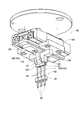
- FIG. 1 shows a component mounter 10.
- the component mounter 10 is a device for performing the mounting operation of components on the circuit substrate 12.
- the component mounter 10 includes an apparatus main body 20, a base material conveyance and holding device 22, a component mounting device 24, imaging devices 26 and 28, a component supply device 30, and a bulk component supply device 32.
- a circuit board, a base material of a three-dimensional structure, etc. are mentioned as circuit base material 12
- a printed wiring board, a printed circuit board, etc. are mentioned as a circuit board.
- the apparatus body 20 is constituted by a frame portion 40 and a beam portion 42 mounted on the frame portion 40.
- the base material transport and holding device 22 is disposed at the center of the frame portion 40 in the front-rear direction, and includes a transport device 50 and a clamp device 52.
- the transfer device 50 is a device for transferring the circuit substrate 12
- the clamp device 52 is a device for holding the circuit substrate 12.
- the base material transport and holding device 22 transports the circuit base material 12 and holds the circuit base material 12 fixedly at a predetermined position.
- the transport direction of the circuit substrate 12 is referred to as the X direction
- the horizontal direction perpendicular to the direction is referred to as the Y direction
- the vertical direction is referred to as the Z direction. That is, the width direction of the component mounter 10 is the X direction, and the front-rear direction is the Y direction.
- the component mounting device 24 is disposed in the beam unit 42 and has two working heads 60 and 62 and a working head moving device 64.
- a component gripping tool 66 is detachably provided on the lower end surface of each working head 60, 62.
- the component gripping tool 66 has a pair of claws 67. By bringing the pair of claws 67 close, the component is gripped, and by separating the pair of claws 67, the gripped component is separated.
- the working head moving device 64 has an X direction moving device 68, a Y direction moving device 70, and a Z direction moving device 72.
- the two working heads 60 and 62 are integrally moved to an arbitrary position on the frame portion 40 by the X-direction moving device 68 and the Y-direction moving device 70.
- the working heads 60 and 62 are detachably mounted on the sliders 74 and 76, and the Z-direction moving device 72 moves the sliders 74 and 76 in the vertical direction separately.
- the work heads 60 and 62 are individually moved in the vertical direction by the Z-direction moving device 72.
- the imaging device 26 is attached to the slider 74 in a state of facing downward, and is moved together with the working head 60 in the X direction, the Y direction, and the Z direction. Thereby, the imaging device 26 captures an arbitrary position on the frame unit 40. As shown in FIG. 1, the imaging device 28 is disposed between the base material conveyance and holding device 22 on the frame portion 40 and the component supply device 30 so as to face upward. Thereby, the imaging device 28 images the component gripped by the component gripping tool 66 of the working heads 60 and 62.
- the component supply device 30 is disposed at one end of the frame portion 40 in the front-rear direction.
- the component supply device 30 has a tray-type component supply device 78 and a feeder-type component supply device (not shown).
- the tray-type component supply device 78 is a device that supplies components in a state of being placed on the tray.
- the feeder type parts supply apparatus is an apparatus for supplying parts by a tape feeder and a stick feeder (not shown).
- the bulk parts supply device 32 is disposed at the other end of the frame portion 40 in the front-rear direction.
- the loose parts feeder 32 is a device for aligning a plurality of parts scattered in a scattered state and supplying the parts in an aligned state. That is, it is an apparatus which aligns a plurality of parts of an arbitrary posture to a predetermined posture and supplies the components of the predetermined posture.
- Examples of components supplied by the component supply device 30 and the bulk component supply device 32 include electronic components such as electronic circuit components, components of solar cells, and components of power modules. Further, there are electronic circuit parts including parts having leads, parts not having leads, and the like.
- the component mounting operation is performed on the circuit substrate 12 held by the substrate conveyance and holding device 22 by the above-described configuration. Specifically, the circuit substrate 12 is conveyed to the working position, and is held fixed by the clamp device 52 at that position. Next, the imaging device 26 moves above the circuit substrate 12 and images the circuit substrate 12. Thereby, information on the error of the holding position of the circuit substrate 12 can be obtained. Further, the component supply device 30 or the bulk component supply device 32 supplies components at a predetermined supply position. Then, either of the working heads 60 and 62 moves above the supply position of the component, and the component gripping tool 66 holds the component.
- the work heads 60 and 62 holding the component move above the imaging device 28, and the component held by the component gripping tool 66 is imaged by the imaging device 28. This provides information on the error in the holding position of the part.
- the working heads 60 and 62 holding the components move to the upper side of the circuit base 12 and correct the holding position error of the circuit base 12, the error of the holding position of the components, etc. Do.
- the component holding tool 66 detaches the component, whereby the component is mounted on the circuit base 12.
- the component holding tool 66 holds the component by the approach of the pair of claws 67 and separates the component by the separation of the pair of claws 67. Installation work is being carried out.
- the electronic components include electronic components having a plurality of pins extending upward and a plurality of pins extending downward, so-called pin header. In such an electronic component, a plurality of upwardly extending pins are gripped by the component gripper 66, and a plurality of downwardly extending pins are inserted into a plurality of through holes formed in the circuit substrate 12.
- the electronic component 80 has a generally block-like component body 82, and three lower pins 84 extending downward from the lower surface of the component body 82; It comprises three upper pins 86 extending upward from the upper surface of the component body 82. Then, the three upper pins 86 of the electronic component 80 are gripped by the pair of claws 67.
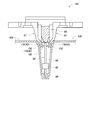
- a contact block 88 is disposed between the pair of claws 67, and when the three upper pins 86 are gripped by the pair of claws 67, 3
- the upper end of the upper pin 86 of the book contacts the lower surface (hereinafter referred to as the “contact surface”) 90 of the contact block 88. That is, when the electronic component 80 is gripped by the component gripping tool 66, the component gripping tool 66 is lowered until the contact surface 90 of the contact block 88 contacts the upper end of the upper pin 86, and the upper end of the upper pin 86 When it contacts the contact surface 90, the pair of claws 67 approach and grip the upper pin 86.
- the component gripping tool 66 that is, the working head 60 to which the component gripping tool 66 is attached is operated by the operation of the working head moving device 64. Move up 12 At this time, the working head is arranged so that the through holes (not shown) formed in the circuit base 12 and the lower pins 84 of the electronic component 80 coincide in XY coordinates, that is, aligned in a straight line in the vertical direction. The operation of the transfer device 64 is controlled. Then, when the working head 60 is lowered, the lower pins 84 of the electronic component 80 are inserted into the through holes formed in the circuit substrate 12.
- the outer diameter of the lower pin 84 is the same as the inner diameter of the through hole or slightly larger than the inner diameter of the through hole. Further, the upper end of the upper pin 86 is in contact with the contact surface 90 of the contact block 88 in a state where the electronic component 80 is held by the component holder 66. Then, with the upper end of the upper pin 86 in contact with the contact surface 90 of the contact block 88, the working head 60 is lowered, and the lower pin 84 of the electronic component 80 is inserted into the through hole. As a result, the upper pin 86 is pushed by the abutting block 88, whereby the lower pin 84 is press-fit into the through hole of the circuit base 12, and the electronic component 80 is mounted on the circuit base 12.
- the electronic component 80 is supplied as a taped component, it may be supplied in an inclined state, and in such a case, the conventional component gripping tool can properly hold the electronic component 80. There is a possibility that it can not be done.
- the taped component 100 is composed of a carrier tape 106 in which a large number of accommodation recesses 102 are formed, and an electronic component 80 accommodated in the accommodation recess 102.
- the housing recess 102 is slightly longer than the length dimension of the electronic component 80, and the electronic component 80 is housed in the housing recess 102 so as to extend in the vertical direction.
- the claw 67 of the component gripping tool 66 is inserted into the gap between the inner wall surface of the housing recess 102 and the upper pin 86 of the electronic component 80 housed in the housing recess 102, and the upper pin 86 is a pair of claws 67. It is held by Further, since the holding position of the electronic component 80 by the component holding tool 66 is a predetermined supply position, the carrier tape 106 extends the carrier tape 106 every time the electronic component 80 is held by the component holding tool 66. In the direction, it is sent out one by one. As a result, the accommodation recess 102 in which the electronic component 80 is accommodated is delivered to the supply position, and a new electronic component 80 is supplied. However, the electronic component 80 accommodated in the accommodation recess 102 may be inclined inside the accommodation recess 102 as the electronic component 80 indicated by a dotted line in FIG. 5 is accompanied by the delivery of the carrier tape 106.
- the conventional component gripping tool 110 is disposed between the pair of claws 112 and the pair of claws 112 as shown in FIGS. And a contact block 114.
- Each of the pair of claws 112 is composed of a grip portion 116, an arm portion 118 and a slide portion 119.
- the gripping portion 116 is a portion that grips the three upper pins 86 of the electronic component 80. For this reason, the dimension in the width direction of the grip portion 116 is longer than the length dimension in the direction in which the three upper pins 86 are arranged. Thereby, the three upper pins 86 are collectively gripped by the pair of claws 112.
- the length dimension in the direction in which the three upper pins 86 are arranged is both ends of the three upper pins 86 in the direction in which the three upper pins 86 are arranged orthogonally to the extending direction of the upper pins 86, The distance between the outer sides of the two upper pins 86 located at the outer side.
- the arm portion 118 is a portion for holding the grip portion 116, and is configured by the main arm portion 120 and the bending portion 122.
- the main arm portion 120 is disposed to extend in the vertical direction, and is connected to the slide portion 119 at an upper end portion.
- the bending portion 122 is continuous downward from the lower end of the main arm portion 120.
- the bending part 122 is bent so that the contact block 114 may be approached, so that it goes to a lower end part.
- the grip portion 116 is fixed to the lower end of the bent portion 122. That is, the arm portion 118 is bent at a lower end portion in a direction approaching the abutting block 114, and the grip portion 116 is fixed to the lower end of the arm portion 118.
- the slide portion 119 is slidably held in the left-right direction by the main body portion 125 of the component gripping tool 110, and the pair of claws 112 slide so as to approach and separate. Therefore, with the sliding of the slide portion 119, when the pair of claws 112 approaches closest to each other, the gripping portions 116 of the pair of claws 112 are in contact with each other. At this time, the pair of arm portions 118 do not contact due to the bending of the bending portion 122, and the pair of arm portions 118 are separated.
- the width dimension of the arm portion 118 is the same as the width dimension of the grip portion 116. For this reason, the width dimension of the claw 112 is uniform in the vertical direction, that is, from the main arm portion 120 to the gripping portion 116. Incidentally, the width dimension is a dimension in the left and right direction orthogonal to the sliding direction of the claw 112.
- the abutment block 114 is disposed between the arm portions 118 of the pair of claws 112, and the width dimension of the abutment block 114 is longer than the lengthwise dimension of the three upper pins 86, and , Slightly longer than the width dimension of the claw 112. Also, the thickness dimension of the abutment block 114 is slightly shorter than the distance between the main arms 120 of the pair of arms 118 when the pair of claws 112 approach closest. The thickness dimension is a dimension in the sliding direction of the claw 112.
- the side surface of the contact block 114 facing the bent portion 122 of the arm portion 118 is a tapered surface 126 over the entire area in the width direction, and the lower surface of the contact block 114 (hereinafter referred to as “contact surface”) As it goes to 128), it inclines toward the inside of the abutment block 88.
- the taper angle of the tapered surface 126 is substantially the same as the bending angle of the bending portion 122 of the arm portion 118. Therefore, when the pair of claws 112 comes closest to each other, the bent portion 122 of the arm portion 118 and the tapered surface 126 of the abutment block 114 face each other, and the arm portion 118 and the abutment block 114 do not interfere with each other.
- Abutment block 114 is located between the arms 118 of the pair of claws 112.
- the lower end portion of the pair of claws 112 receives the taped component 100 by lowering the working head 60 mounted with the component holding tool 110 in a state where the pair of claws 112 are separated. It is inserted into the inside of the recess 102. At this time, the lower end portions of the pair of claws 112 of the accommodation recess 102 are positioned such that the upper pins 86 of the electronic component 80 accommodated in the accommodation recess 102 are positioned between the gripping portions 116 of the pair of claws 112. It is inserted inside.
- the upper end of the upper pin 86 of the electronic component 80 abuts on the abutting surface 128 of the abutting block 114 located between the pair of claws 112, and the pair of claws 112 approaches, thereby the upper pin 86 Are gripped by the grips 116 of the pair of claws 112.
- the upper end of the upper pin 86 of the electronic component 80 inserted between the lower ends of the pair of claws 112 is In some cases, the contact surface 128 of the abutment block 114 does not contact, and it may enter between the abutment block 114 and the claw 112. In such a case, the upper end of the upper pin 86 is caught between the tapered surface 126 of the abutment block 114 and the claws 112, so that the pair of claws 112 can not be approached. The upper pin 86 can not be gripped.
- the width dimension of the arm portion 150 of the claw 67 is narrower than the width dimension of the gripping portion 152, and the arm of the abutment block 88
- a tapered surface (see FIG. 4) 156 is formed only on a part of the side surface facing the portion 150 in the width direction. Then, when the pair of claws 67 approaches, the arm portion 150 and the tapered surface 156 face each other, and the interference between the arm portion 150 and the abutment block 88 is prevented. Thereby, the upper pin 86 of the electronic component 80 can be gripped by the grip portion 152 without causing the arm portion 150 and the contact block 88 to interfere with each other.
- the thickness dimension of the contact surface 90 of the contact block 88 excludes the formation portion of the tapered surface 156
- the distance between the pair of grips 152 is longer.
- at least two or more upper pins 86 of the electronic component 80 in the state in the thickest thickness direction of the contact surface 90 contact the contact surface 90 It is set to abut.
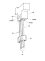
- each of the pair of claws 67 is configured of a grip portion 152, an arm portion 150, and a slide portion 158.
- the gripping portion 152 is a portion for gripping the three upper pins 86 of the electronic component 80, and the width dimension of the gripping portion 152 is the same as that of the gripping portion 116 of the conventional component gripping tool 110. It is longer than the length dimension of the lined direction.
- the arm portion 150 is a portion for holding the grip portion 152, and the width dimension of the arm portion 150 is about 1/3 of the width dimension of the grip portion 152.
- the arm portion 150 is configured of a main arm portion 160 and a bending portion 162.
- the main arm portion 160 is disposed to extend in the vertical direction, and is connected to the slide portion 158 at an upper end portion.
- the bending portion 162 continues downward from the lower end of the main arm portion 160. And the bending part 162 is bent so that the contact
- the lower end of the bent portion 162 is fixed to the central portion in the width direction of the grip portion 152.
- the arm portion 150 is bent at a lower end portion in a direction approaching the abutment block 88, and the grip portion 152 has a width dimension of about three times the width dimension of the arm portion 150 at the lower end of the arm portion 150. Is fixed.
- the slide portion 158 is slidably held in the left-right direction by the main body portion 166 of the component holding tool 66, and the pair of claws 67 slide so as to approach and separate. Therefore, with the sliding of the slide portion 158, when the pair of claws 67 approaches closest, the gripping portions 152 of the pair of claws 67 are in contact with each other. At this time, the pair of arm portions 150 does not contact due to the bending of the bending portion 162, and the pair of arm portions 150 is separated.
- the abutting block 88 is disposed between the arm portions 150 of the pair of claws 67.
- the width dimension of the abutment block 88 is slightly longer than the width dimension of the grip portion 152 (see FIG. 3).
- the thickness dimension of the contact block 88 is such that the main arm portion 160 of the pair of arm portions 150 when the pair of claws 67 comes closest to each other so as not to interfere when the pair of claws 67 operate. Slightly shorter than the distance between them (see FIG. 4).
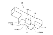
- the side surface 170 opposed to the pair of arm portions 150 of the abutting block 88 is a tapered surface 156 in a part in the width direction, and the tapered surface 156 is an abutting surface 90 of the abutting block 88.
- the tapered surface 156 is an abutting surface 90 of the abutting block 88.
- a recess 174 is formed at the center of the corner 172 where the contact surface 90 of the contact block 88 and the side surface 170 intersect.
- the concave portion 174 has a shape in which the center of the corner portion 172 is cut away from the contact surface 90 to the side surface 170 and is formed at a position facing the bending portion 162 of the arm portion 150.
- the bottom surface of the recess 174 is a tapered surface 156.
- Recesses 174 are formed on a pair of side surfaces 170 and abutment surface 90 opposed to a pair of arm portions 150 of abutment block 88, and a pair of depressions 174 formed on a pair of side surfaces 170. Is a symmetrical shape.
- the abutment surface 90 is generally H-shaped due to the recess block 174 extending from the abutment surface 90 to the side surface 170 in the abutment block 88. For this reason, the location where the recess 174 of the abutment surface 90 is formed, that is, the central portion in the width direction of the abutment surface 90 is recessed and the thickness dimension is short. On the other hand, portions of the abutting surface 90 where the concave portions 174 are not formed, that is, both end portions in the width direction of the abutting surface 90 have a long thickness dimension.
- the contact surface 90 is a first surface 176 having a short thickness in the central portion in the width direction, and is a second surface 178 having a long thickness in the both ends in the width direction.
- the thickness dimension of the second surface 178 is longer than the distance between the pair of gripping portions 152 in the state in which the pair of claws 67 is most separated.
- the first surface 176 and the second surface 178 are continuous on one surface.
- the bottom surface of the concave portion 174 that is, the taper angle of the tapered surface 156 is substantially the same as the bending angle of the bending portion 162 of the arm portion 150.
- the width dimension of the recess 174 is slightly larger than the width dimension of the bent portion 162. For this reason, when the pair of claws 67 approaches, as shown in FIG. 3, the bent portion 162 of the arm portion 150 enters the concave portion 174 of the abutment block 88.
- the abutment block 88 is disposed between the arm portions 150 of the pair of claws 67 without interference between the arm portion 150 and the abutment block 88.
- the lower end portion of the pair of claws 67 is, as shown in FIG. , Is inserted into the inside of the receiving recess 102 of the taped component 100.
- the lower end portion of the pair of claws 67 of the accommodation recess 102 is positioned so that the upper pin 86 of the electronic component 80 accommodated in the accommodation recess 102 is positioned between the gripping portions 152 of the pair of claws 67. It is inserted inside.
- the upper end of the three upper pins 86 of the electronic component 80 abuts on the abutment surface 90 of the abutment block 88 located between the pair of claws 67.
- the central upper pin 86 of the three upper pins 86 abuts on the first surface 176 of the abutment surface 90, and the upper pins 86 at both ends of the three upper pins 86 abut It abuts on the second surface 178 of the surface 90.
- the three upper pins 86 are gripped by the grip portions 116 of the pair of claws 67.
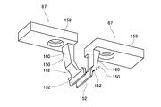
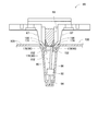
- the upper pin 86 of the electronic component 80 can be appropriately gripped by the component gripping tool 66. More specifically, as shown in FIGS. 11 and 12, when the electronic component 80 is inclined inside the accommodation recess 102, the three electronic components 80 inserted between the lower ends of the pair of claws 67. The central upper pin 86 of the upper pins 86 does not abut the first surface 176 of the abutment surface 90 of the abutment block 88. In FIG. 12, the taped component 100, the claws 67, and the like are omitted.
- the upper pins 86 at both ends of the three upper pins 86 of the electronic component 80 inserted between the lower ends of the pair of claws 67 are the second surface 178 of the contact surface 90 of the contact block 88. Abut on.
- the electronic component 80 is largely inclined. Even if the upper pins 86 at both ends abut the second surface 178. For this reason, the upper end of the central upper pin 86 not in contact with the abutment surface 90 of the three upper pins 86 does not enter the inside of the recess 174.
- the upper pins 86 at both ends of the three upper pins 86 that determine the length dimension of the upper pins 86 in a row direction are in contact with the contact surface 90 of the contact block 88, As the claw 67 approaches, the three upper pins 86 are pushed by the grip portion 152 of the claw 67 and oscillated. At this time, the inclination of the electronic component 80 is corrected, and the three upper pins 86 abut on the abutment surface 90 of the abutment block 88. That is, the central upper pin 86 of the three upper pins 86 abuts on the first surface 176 of the abutment surface 90, and the upper pins 86 at both ends of the three upper pins 86 are abutment surfaces.
- the three upper pins 86 are gripped by the grip portion 152 of the claw 67 by the approach of the pair of claws 67.
- the upper pin 86 of the electronic component 80 is in contact with the contact surface 90. Can be held by the holding unit 152.
- the component gripping tool 66 is an example of a component gripping tool.
- the nail 67 is an example of a nail.
- the electronic component 80 is an example of an electronic component.
- the upper pin 86 is an example of a pin or a lead.
- the contact surface 90 is an example of the contact surface.
- the recess 174 is an example of a relief and a recess.
- the present invention is not limited to the above embodiments, and can be implemented in various modes in which various changes and improvements are made based on the knowledge of those skilled in the art.
- the abutting surface 90 of the abutting block 88 the first surface 176 and the second surface 178 are continuous on one surface, but the abutting surface is one surface. It is possible to make it a non-continuous surface, that is, a non-continuous surface.
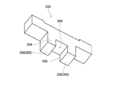
- a recess 204 is formed on the bottom surface of the abutment block 200, that is, on the abutment surface 202.
- the recess 204 is shaped to be cut away from the abutment surface 202 to the pair of side surfaces 206. That is, the contact surface 202 of the contact block 200 is divided by the recess at the central portion in the width direction to form two third surfaces 208. And when the contact block 200 of such a structure is employ
- the present invention is applied to the electronic component 80 having the lower pin 84 and the upper pin 86, but in the case of the electronic component having the upper pin 86, various kinds of components can be used. It is possible to apply the present invention. That is, the present invention can be applied to an electronic component having a plurality of pins held by the pair of claws 67 of the component holding tool 66. In addition, it is easy to apply to the various aspect made to contact two or more upper pins of electronic parts provided with a plurality of upper pins on a contact side. For example, two or more upper pins in contact with the contact surface of electronic components having a plurality of upper pins may be asymmetrically selected, and the shape of the contact surface may be asymmetric.
- the upper pins to be gripped may be selected asymmetrically.
- the length dimension of the direction in which the upper pins are arranged may exceed the width dimension of the contact surface or the grip portion of the claw. That is, there may be no correlation between the upper pin gripped by the grip and the upper pin abutting the contact surface.
- the contact block 88 of the above embodiment is a consumable item, it only needs to be one component of the component gripping tool 66 configured to be replaceable, and the main body portion 166 forming the main body of the component gripping tool 66
- the contact block 88 may be integrally configured.
- the present invention can be applied to an electronic component housed in a tray provided with a plurality of cavities having a large number of housing recess shapes, an electronic component etc. supplied in an inclined state.
Landscapes
- Engineering & Computer Science (AREA)
- Manufacturing & Machinery (AREA)
- Microelectronics & Electronic Packaging (AREA)
- Mechanical Engineering (AREA)
- Supply And Installment Of Electrical Components (AREA)
- Manipulator (AREA)
Abstract
電子部品の複数のピン又はリードを把持する1対の爪と、1対の爪の間に配設され、1対の爪により把持された複数のピン又はリードのうちの2以上のピン又はリードの先端に当接する当接面とを備え、1対の爪が前記複数のピン又はリードを把持している状態で、1対の爪と当接面とが干渉しないように、当接面に逃げ部が形成された部品把持具。
Description
本発明は、1対の爪の接近により電子部品を把持する部品把持具に関するものである。
部品把持具には、下記特許文献に記載されているように、1対の爪の接近により電子部品を把持するものがある。
本発明は、1対の爪の接近により電子部品を適切に把持することである。
上記課題を解決するために、本明細書は、電子部品の複数のピン又はリードを把持する1対の爪と、前記1対の爪の間に配設され、前記1対の爪により把持された複数のピン又はリードのうちの2以上のピン又はリードの先端に当接する当接面とを備え、前記1対の爪が前記複数のピン又はリードを把持している状態で、前記1対の爪と前記当接面とが干渉しないように、前記当接面に逃げ部が形成された部品把持具を開示する。
本開示では、1対の爪の間に配設された当接面に、1対の爪により把持された複数のピン又はリードのうちの2以上のピン又はリードの先端が当接する。また、1対の爪が複数のピン又はリードを把持している状態で、1対の爪と当接面とが干渉しないように、当接面に逃げ部が形成されている。これにより、爪と当接面との干渉を抑制し、1対の爪の接近により電子部品を適切に把持することが可能となる。
以下、本発明を実施するための形態として、本発明の実施例を、図を参照しつつ詳しく説明する。
(A)部品実装機の構成
図1に、部品実装機10を示す。部品実装機10は、回路基材12に対する部品の実装作業を実行するための装置である。部品実装機10は、装置本体20、基材搬送保持装置22、部品装着装置24、撮像装置26,28、部品供給装置30、ばら部品供給装置32を備えている。なお、回路基材12として、回路基板、三次元構造の基材等が挙げられ、回路基板として、プリント配線板、プリント回路板等が挙げられる。
図1に、部品実装機10を示す。部品実装機10は、回路基材12に対する部品の実装作業を実行するための装置である。部品実装機10は、装置本体20、基材搬送保持装置22、部品装着装置24、撮像装置26,28、部品供給装置30、ばら部品供給装置32を備えている。なお、回路基材12として、回路基板、三次元構造の基材等が挙げられ、回路基板として、プリント配線板、プリント回路板等が挙げられる。
装置本体20は、フレーム部40と、そのフレーム部40に上架されたビーム部42とによって構成されている。基材搬送保持装置22は、フレーム部40の前後方向の中央に配設されており、搬送装置50とクランプ装置52とを有している。搬送装置50は、回路基材12を搬送する装置であり、クランプ装置52は、回路基材12を保持する装置である。これにより、基材搬送保持装置22は、回路基材12を搬送するとともに、所定の位置において、回路基材12を固定的に保持する。なお、以下の説明において、回路基材12の搬送方向をX方向と称し、その方向に直角な水平の方向をY方向と称し、鉛直方向をZ方向と称する。つまり、部品実装機10の幅方向は、X方向であり、前後方向は、Y方向である。
部品装着装置24は、ビーム部42に配設されており、2台の作業ヘッド60,62と作業ヘッド移動装置64とを有している。各作業ヘッド60,62の下端面には、図2に示すように、部品把持具66が着脱可能に設けられている。部品把持具66は、1対の爪67を有しており、それら1対の爪67を接近させることで、部品を把持し、1対の爪67を離間させることで、把持した部品を離脱する。また、作業ヘッド移動装置64は、X方向移動装置68とY方向移動装置70とZ方向移動装置72とを有している。そして、X方向移動装置68とY方向移動装置70とによって、2台の作業ヘッド60,62は、一体的にフレーム部40上の任意の位置に移動させられる。また、各作業ヘッド60,62は、スライダ74,76に着脱可能に装着されており、Z方向移動装置72は、スライダ74,76を個別に上下方向に移動させる。つまり、作業ヘッド60,62は、Z方向移動装置72によって、個別に上下方向に移動させられる。
撮像装置26は、下方を向いた状態でスライダ74に取り付けられており、作業ヘッド60とともに、X方向,Y方向およびZ方向に移動させられる。これにより、撮像装置26は、フレーム部40上の任意の位置を撮像する。撮像装置28は、図1に示すように、フレーム部40上の基材搬送保持装置22と部品供給装置30との間に、上を向いた状態で配設されている。これにより、撮像装置28は、作業ヘッド60,62の部品把持具66に把持された部品を撮像する。
部品供給装置30は、フレーム部40の前後方向での一方側の端部に配設されている。部品供給装置30は、トレイ型部品供給装置78とフィーダ型部品供給装置(図示省略)とを有している。トレイ型部品供給装置78は、トレイ上に載置された状態の部品を供給する装置である。フィーダ型部品供給装置は、テープフィーダ、スティックフィーダ(図示省略)によって部品を供給する装置である。
ばら部品供給装置32は、フレーム部40の前後方向での他方側の端部に配設されている。ばら部品供給装置32は、ばらばらに散在された状態の複数の部品を整列させて、整列させた状態で部品を供給する装置である。つまり、任意の姿勢の複数の部品を、所定の姿勢に整列させて、所定の姿勢の部品を供給する装置である。なお、部品供給装置30および、ばら部品供給装置32によって供給される部品として、電子回路部品,太陽電池の構成部品,パワーモジュールの構成部品等の電子部品が挙げられる。また、電子回路部品には、リードを有する部品,リードを有さない部品等が有る。
(B)部品実装機の作動
部品実装機10では、上述した構成によって、基材搬送保持装置22に保持された回路基材12に対して部品の装着作業が行われる。具体的には、回路基材12が、作業位置まで搬送され、その位置において、クランプ装置52によって固定的に保持される。次に、撮像装置26が、回路基材12の上方に移動し、回路基材12を撮像する。これにより、回路基材12の保持位置の誤差に関する情報が得られる。また、部品供給装置30若しくは、ばら部品供給装置32は、所定の供給位置において、部品を供給する。そして、作業ヘッド60,62の何れかが、部品の供給位置の上方に移動し、部品把持具66によって部品を保持する。続いて、部品を保持した作業ヘッド60,62が、撮像装置28の上方に移動し、撮像装置28によって、部品把持具66に保持された部品が撮像される。これにより、部品の保持位置の誤差に関する情報が得られる。続いて、部品を保持した作業ヘッド60,62が、回路基材12の上方に移動し、保持している部品を、回路基材12の保持位置の誤差,部品の保持位置の誤差等を補正する。そして、部品把持具66が部品を離脱することで、回路基材12に部品が装着される。
部品実装機10では、上述した構成によって、基材搬送保持装置22に保持された回路基材12に対して部品の装着作業が行われる。具体的には、回路基材12が、作業位置まで搬送され、その位置において、クランプ装置52によって固定的に保持される。次に、撮像装置26が、回路基材12の上方に移動し、回路基材12を撮像する。これにより、回路基材12の保持位置の誤差に関する情報が得られる。また、部品供給装置30若しくは、ばら部品供給装置32は、所定の供給位置において、部品を供給する。そして、作業ヘッド60,62の何れかが、部品の供給位置の上方に移動し、部品把持具66によって部品を保持する。続いて、部品を保持した作業ヘッド60,62が、撮像装置28の上方に移動し、撮像装置28によって、部品把持具66に保持された部品が撮像される。これにより、部品の保持位置の誤差に関する情報が得られる。続いて、部品を保持した作業ヘッド60,62が、回路基材12の上方に移動し、保持している部品を、回路基材12の保持位置の誤差,部品の保持位置の誤差等を補正する。そして、部品把持具66が部品を離脱することで、回路基材12に部品が装着される。
(C)部品把持具の構造
上述したように、部品実装機10では、部品把持具66が、1対の爪67の接近により部品を把持し、1対の爪67の離間により部品を離脱することで、装着作業が行われている。また、電子部品には、上方に延び出す複数のピンと、下方に延び出す複数のピンとを有する電子部品、所謂、ピンヘッダがある。このような電子部品では、上方に延び出す複数のピンが、部品把持具66により把持され、下方に延び出す複数のピンが、回路基材12に形成された複数の貫通穴に挿入される。
上述したように、部品実装機10では、部品把持具66が、1対の爪67の接近により部品を把持し、1対の爪67の離間により部品を離脱することで、装着作業が行われている。また、電子部品には、上方に延び出す複数のピンと、下方に延び出す複数のピンとを有する電子部品、所謂、ピンヘッダがある。このような電子部品では、上方に延び出す複数のピンが、部品把持具66により把持され、下方に延び出す複数のピンが、回路基材12に形成された複数の貫通穴に挿入される。
具体的には、例えば、電子部品80は、図3に示すように、概してブロック状の部品本体部82と、部品本体部82の下面から下方に向かって延び出す3本の下方ピン84と、部品本体部82の上面から上方に向かって延び出す3本の上方ピン86とにより構成されている。そして、電子部品80の3本の上方ピン86が、1対の爪67によって、把持される。
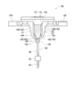
なお、1対の爪67の間には、図4に示すように、当接ブロック88が配設されており、1対の爪67により3本の上方ピン86が把持される際に、3本の上方ピン86の上端が、当接ブロック88の下面(以下、「当接面」と記載する)90に接触する。つまり、部品把持具66により電子部品80が把持される際に、上方ピン86の上端に当接ブロック88の当接面90が接触するまで、部品把持具66が下降され、上方ピン86の上端が当接面90に接触したときに、1対の爪67が接近し、上方ピン86を把持する。
次に、上方ピン86が1対の爪67により把持されると、部品把持具66、つまり、部品把持具66が取り付けられた作業ヘッド60が、作業ヘッド移動装置64の作動により、回路基材12の上方に移動する。この際、回路基材12に形成された貫通穴(図示省略)と、電子部品80の下方ピン84とがXY座標において一致するように、つまり、上下方向に一直線上に並ぶように、作業ヘッド移動装置64の作動が制御される。そして、作業ヘッド60が下降することで、回路基材12に形成された貫通穴に、電子部品80の下方ピン84が挿入される。
なお、下方ピン84の外径は貫通穴の内径と同じ、若しくは、貫通穴の内径より僅かに大きくされている。また、電子部品80が部品把持具66に把持されている状態において、上方ピン86の上端が当接ブロック88の当接面90に接触している。そして、上方ピン86の上端が当接ブロック88の当接面90に接触した状態で、作業ヘッド60が下降し、電子部品80の下方ピン84が貫通穴に挿入される。これにより、上方ピン86が当接ブロック88により押し込まれることで、下方ピン84が回路基材12の貫通穴に圧入されて、電子部品80が回路基材12に装着される。
しかしながら、電子部品80は、テープ化部品として供給されるため、傾斜した状態で供給される場合があり、そのような場合に、従来の部品把持具では、電子部品80を適切に把持することができない虞がある。具体的には、図5に示すように、テープ化部品100は、多数の収容凹部102が形成されたキャリアテープ106と、収容凹部102に収容される電子部品80とから構成されている。収容凹部102は、電子部品80の長さ寸法より僅かに長くされており、その収容凹部102の内部に、電子部品80が上下方向に延びる姿勢で収容されている。
そして、収容凹部102の内壁面と、その収容凹部102に収容された電子部品80の上方ピン86との隙間に、部品把持具66の爪67が挿入され、上方ピン86が1対の爪67により把持される。また、部品把持具66による電子部品80の把持位置は、所定の供給位置とされているため、電子部品80が部品把持具66により把持される毎に、キャリアテープ106は、キャリアテープ106の延びる方向に、順次、送り出される。これにより、電子部品80の収容された収容凹部102が、供給位置に送り出され、新たな電子部品80が供給される。しかしながら、収容凹部102に収容された電子部品80は、キャリアテープ106の送り出しに伴って、図5中の点線で示す電子部品80のように、収容凹部102の内部において傾斜する虞がある。
一方で、従来の部品把持具110は、上記部品把持具66と同様に、図6及び図7に示すように、1対の爪112と、それら1対の爪112の間に配設された当接ブロック114とを有している。1対の爪112の各々は、把持部116とアーム部118とスライド部119とにより構成されている。把持部116は、電子部品80の3本の上方ピン86を把持する部分である。このため、把持部116の幅方向の寸法は、3本の上方ピン86の並ぶ方向の長さ寸法より長くされている。これにより、1対の爪112によって、3本の上方ピン86が纏めて把持される。なお、3本の上方ピン86の並ぶ方向の長さ寸法とは、上方ピン86の延びる方向と直行して3本の上方ピン86が並ぶ方向において、3本の上方ピン86の両端であり、大外に位置する2本の上方ピン86の大外間の距離である。
また、アーム部118は、把持部116を保持する部分であり、主アーム部120と屈曲部122とにより構成されている。主アーム部120は、上下方向に延びるように配設されており、上端部において、スライド部119に連結されている。また、屈曲部122は、主アーム部120の下端から下方に向かって連続している。そして、屈曲部122は、下端部に向かうほど、当接ブロック114に接近するように屈曲している。その屈曲部122の下端に、把持部116が固定されている。つまり、アーム部118は、下端部において、当接ブロック114に接近する方向に屈曲しており、アーム部118の下端に把持部116が固定されている。
また、スライド部119は、部品把持具110の本体部125により、左右方向にスライド可能に保持されており、1対の爪112は接近・離間するようにスライドする。このため、スライド部119のスライドに伴って、1対の爪112が最接近することで、1対の爪112の把持部116が接触する。この際、1対のアーム部118は、屈曲部122の屈曲により接触せず、1対のアーム部118は離間している。
なお、アーム部118の幅寸法は、把持部116の幅寸法と同じとされている。このため、爪112の幅寸法は、上下方向に渡って、つまり、主アーム部120から把持部116に至るまで、均一とされている。ちなみに、幅寸法は、爪112のスライド方向と直行する左右の方向の寸法である。
当接ブロック114は、1対の爪112のアーム部118の間に配設されており、当接ブロック114の幅寸法は、3本の上方ピン86の並ぶ方向の長さ寸法より長く、かつ、爪112の幅寸法より僅かに長くされている。また、当接ブロック114の厚さ寸法は、1対の爪112が最接近した際の1対のアーム部118の主アーム部120の間の距離より僅かに短くされている。なお、厚さ寸法は、爪112のスライド方向における寸法である。ただし、当接ブロック114のアーム部118の屈曲部122と対向する側面は、幅方向の全域に亘って、テーパ面126とされており、当接ブロック114の下面(以下、「当接面」と記載する)128に向かうほど、当接ブロック88の内部に向かうように傾斜している。このテーパ面126のテーパ角度は、アーム部118の屈曲部122の屈曲角度と略同じとされている。このため、1対の爪112が最接近した際に、アーム部118の屈曲部122と当接ブロック114のテーパ面126とが対向し、アーム部118と当接ブロック114とが干渉することなく、1対の爪112のアーム部118の間に、当接ブロック114が位置する。
このような構造において、1対の爪112が離間した状態で、部品把持具110の装着された作業ヘッド60が下降することで、1対の爪112の下端部が、テープ化部品100の収容凹部102の内部に挿入される。この際、1対の爪112の把持部116の間に、収容凹部102に収容されている電子部品80の上方ピン86が位置するように、1対の爪112の下端部が収容凹部102の内部に挿入される。そして、1対の爪112の間に位置する当接ブロック114の当接面128に、電子部品80の上方ピン86の上端が当接し、1対の爪112が接近することで、上方ピン86が、1対の爪112の把持部116により把持される。
しかしながら、図7に示すように、電子部品80が収容凹部102の内部において傾斜していると、1対の爪112の下端部の間に挿入された電子部品80の上方ピン86の上端が、当接ブロック114の当接面128に接触せず、当接ブロック114と爪112との間に入り込む場合がある。このような場合には、上方ピン86の上端が当接ブロック114のテーパ面126と爪112との間に引っ掛かり、1対の爪112を接近させることができず、1対の爪112により、上方ピン86を把持することができない。
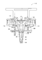
このようなことに鑑みて、部品把持具66では、図3に示すように、爪67のアーム部150の幅寸法が、把持部152の幅寸法より狭くされており、当接ブロック88のアーム部150と対向する側面のうちの幅方向における一部にのみ、テーパ面(図4参照)156が形成されている。そして、1対の爪67が接近した際に、アーム部150とテーパ面156とが対向し、アーム部150と当接ブロック88との干渉が防止される。これにより、アーム部150と当接ブロック88とを干渉させることなく、把持部152により電子部品80の上方ピン86を把持することができる。また、当接ブロック88の側面の幅方向における一部にのみ、テーパ面156が形成されることで、当接ブロック88の当接面90の厚さ寸法は、テーパ面156の形成箇所を除いて、1対の把持部152の間の距離より長くされている。そして、当接面90の最も厚い厚さ方向の寸法は、電子部品80が傾いた状態で供給されたとしても、その状態の電子部品80の少なくとも2以上の上方ピン86が当接面90に当接するように設定されている。これにより、テープ化部品100の収容凹部102の内部で傾斜している電子部品80の上方ピン86が、1対の爪67により把持される際に、当接ブロック88の当接面90に、少なくとも2以上の上方ピン86の上端を当接させ、1対の爪67により適切に上方ピン86を把持することが可能となる。
具体的に、1対の爪67の各々は、図8に示すように、把持部152とアーム部150とスライド部158とにより構成されている。把持部152は、電子部品80の3本の上方ピン86を把持する部分であり、把持部152の幅寸法は、従来の部品把持具110の把持部116と同様に、3本の上方ピン86の並ぶ方向の長さ寸法より長くされている。
また、アーム部150は、把持部152を保持する部分であり、アーム部150の幅寸法は、把持部152の幅寸法の1/3程度とされている。アーム部150は、主アーム部160と屈曲部162とにより構成されている。主アーム部160は、上下方向に延びるように配設されており、上端部において、スライド部158に連結されている。また、屈曲部162は、主アーム部160の下端から下方に向かって連続している。そして、屈曲部162は、図4に示すように、下端部に向かうほど、当接ブロック88に接近するように屈曲している。その屈曲部162の下端は、把持部152の幅方向における中央部に固定されている。つまり、アーム部150は、下端部において、当接ブロック88に接近する方向に屈曲しており、アーム部150の下端に、アーム部150の幅寸法の約3倍の幅寸法を有する把持部152が固定されている。
また、スライド部158は、図4に示すように、部品把持具66の本体部166により、左右方向にスライド可能に保持されており、1対の爪67は接近・離間するようにスライドする。このため、スライド部158のスライドに伴って、1対の爪67が最接近することで、1対の爪67の把持部152が接触する。この際、1対のアーム部150は、屈曲部162の屈曲により接触せず、1対のアーム部150は離間している。
また、当接ブロック88は、図3及び図4に示すように、1対の爪67のアーム部150の間に配設されている。そして、当接ブロック88の幅寸法は、把持部152の幅寸法より僅かに長くされている(図3参照)。また、当接ブロック88の厚さ寸法は、1対の爪67が動作した際に干渉しないように、1対の爪67が最接近した際の1対のアーム部150の主アーム部160の間の距離より僅かに短くされている(図4参照)。ただし、当接ブロック88の1対のアーム部150と対向する側面170は、幅方向の一部において、テーパ面156とされており、そのテーパ面156は、当接ブロック88の当接面90に向かうほど、当接ブロック88の内部に向かうように傾斜している。
詳しくは、図9に示すように、当接ブロック88の当接面90と側面170とが交差する角部172の中央に、凹部174が形成されている。凹部174は、角部172の中央が当接面90から側面170に至るまで切り欠かれた形状をなし、アーム部150の屈曲部162と対向する位置に形成されている。そして、その凹部174の底面が、テーパ面156とされている。なお、凹部174は、当接ブロック88の1対のアーム部150と対向する1対の側面170及び当接面90に形成されており、1対の側面170に形成された1対の凹部174は、対称的な形状とされている。
このように、当接ブロック88に当接面90から側面170に至る凹部174が形成されることで、当接面90は、概してH型形状をなす。このため、当接面90の凹部174が形成されている箇所、つまり、当接面90の幅方向における中央部
は、凹んでおり、厚さ寸法は短い。一方、当接面90の凹部174が形成されていない箇所、つまり、当接面90の幅方向における両端部は、厚さ寸法が長い。つまり、当接面90は、幅方向における中央部において、厚さ寸法の短い第1面176とされており、幅方向における両端部において、厚さ寸法の長い第2面178とされている。ちなみに、第2面178の厚さ寸法は、1対の爪67が最も離間した状態での1対の把持部152の間の距離より長くされている。また、第1面176と第2面178とは1面で連続している。
は、凹んでおり、厚さ寸法は短い。一方、当接面90の凹部174が形成されていない箇所、つまり、当接面90の幅方向における両端部は、厚さ寸法が長い。つまり、当接面90は、幅方向における中央部において、厚さ寸法の短い第1面176とされており、幅方向における両端部において、厚さ寸法の長い第2面178とされている。ちなみに、第2面178の厚さ寸法は、1対の爪67が最も離間した状態での1対の把持部152の間の距離より長くされている。また、第1面176と第2面178とは1面で連続している。
また、凹部174の底面、つまり、テーパ面156のテーパ角度は、アーム部150の屈曲部162の屈曲角度と略同じとされている。そして、凹部174の幅寸法は、屈曲部162の幅寸法より僅かに大きくされている。このため、1対の爪67が接近した際に、図3に示すように、アーム部150の屈曲部162が、当接ブロック88の凹部174に入り込む。このように、アーム部150と当接ブロック88とが干渉することなく、1対の爪67のアーム部150の間に、当接ブロック88が配置されている。
このような構造において、1対の爪67が離間した状態で、部品把持具66の装着された作業ヘッド60が下降することで、図10に示すように、1対の爪67の下端部が、テープ化部品100の収容凹部102の内部に挿入される。この際、1対の爪67の把持部152の間に、収容凹部102に収容されている電子部品80の上方ピン86が位置するように、1対の爪67の下端部が収容凹部102の内部に挿入される。そして、部品把持具66の下降に伴って、1対の爪67の間に位置する当接ブロック88の当接面90に、電子部品80の3本の上方ピン86の上端が当接する。この際、3本の上方ピン86のうちの中央の上方ピン86は、当接面90の第1面176に当接し、3本の上方ピン86のうちの両端の上方ピン86は、当接面90の第2面178に当接する。そして、1対の爪67が接近することで、3本の上方ピン86が、1対の爪67の把持部116により把持される。
また、電子部品80が収容凹部102の内部において傾斜している場合であっても、その電子部品80の上方ピン86を、部品把持具66により適切に把持することが可能である。詳しくは、図11及び図12に示すように、電子部品80が収容凹部102の内部において傾斜していると、1対の爪67の下端部の間に挿入された電子部品80の3本の上方ピン86のうちの中央の上方ピン86は、当接ブロック88の当接面90の第1面176に当接しない。なお、図12では、テープ化部品100,爪67等が省略されている。
一方、1対の爪67の下端部の間に挿入された電子部品80の3本の上方ピン86のうちの両端の上方ピン86は、当接ブロック88の当接面90の第2面178に当接する。特に、第2面178の厚さ寸法は、1対の爪67が最も離間した状態での1対の把持部152の間の距離より長くされているため、電子部品80が大きく傾斜している場合であっても、両端の上方ピン86は第2面178に当接する。このため、3本の上方ピン86のうちの当接面90に当接しない中央の上方ピン86の上端は、凹部174の内部に入り込まない。
そして、上方ピン86の並ぶ方向の長さ寸法を決定する3本の上方ピン86のうちの両端の上方ピン86が、当接ブロック88の当接面90に当接している状態で、1対の爪67が接近することで、3本の上方ピン86が爪67の把持部152に押されて搖動する。この際、電子部品80の傾斜が是正され、3本の上方ピン86が当接ブロック88の当接面90に当接する。つまり、3本の上方ピン86のうちの中央の上方ピン86は、当接面90の第1面176に当接し、3本の上方ピン86のうちの両端の上方ピン86は、当接面90の第2面178に当接する。そして、1対の爪67の接近により、3本の上方ピン86が爪67の把持部152により把持される。このように、部品把持具66では、電子部品80が収容凹部102の内部において傾斜している場合であっても、その電子部品80の上方ピン86を、当接面90に当接させた状態で、把持部152により把持することができる。
なお、部品把持具66は、部品把持具の一例である。爪67は、爪の一例である。電子部品80は、電子部品の一例である。上方ピン86は、ピン又はリードの一例である。当接面90は、当接面の一例である。凹部174は、逃げ部及び、凹部の一例である。
また、本発明は、上記実施例に限定されるものではなく、当業者の知識に基づいて種々の変更、改良を施した種々の態様で実施することが可能である。具体的には、例えば、上記実施例では、当接ブロック88の当接面90において、第1面176と第2面178とが1面で連続しているが、当接面を1面で連続しない面、つまり、非連続面とすることが可能である。詳しくは、図13に示すように、当接ブロック200の底面、つまり、当接面202には、凹部204が形成されている。凹部204は、当接面202から1対の側面206に至るまで切り欠かれた形状とされている。つまり、当接ブロック200の当接面202は、幅方向の中央部において、凹部により分断され、2つの第3面208とされている。そして、このような構造の当接ブロック200が採用された場合において、図14に示すように、電子部品80が傾斜していると、3本の上方ピン86のうちの両端の上方ピン86が、当接面202、つまり、第3面208に当接する。これにより、当接ブロック200を採用した部品把持具においても、上述した部品把持具66と同様の効果を奏することができる。なお、当接ブロック200を採用した部品把持具では、3本の上方ピン86のうちの両端の上方ピン86、つまり、2本の上方ピン86が当接面202に当接する。
また、上記実施例では、下方ピン84と上方ピン86とを有する電子部品80に本発明が適用されているが、上方ピン86を有している電子部品であれば、種々の種類の部品に本発明を適用することが可能である。つまり、部品把持具66の1対の爪67により把持される複数のピンを有する電子部品に、本発明を適用することが可能である。なお、複数本の上方ピンを備えた電子部品のうちの2本以上の上方ピンを当接面に当接させる様々な態様に適用することは容易である。例えば、複数本の上方ピンを備えた電子部品のうちの当接面に当接する2本以上の上方ピンを非対称に選定することもあり、当接面の形状が非対称形であることもある。同様に、全ての上方ピンを把持する必要はなく、把持する上方ピンを非対称に選定することもある。また、上方ピンの並ぶ方向の長さ寸法が当接面や爪の把持部の幅寸法を超えることもある。つまり、把持部で把持する上方ピンと当接面に当接する上方ピンとに相関的な関係が認められない場合もある
なお、上記実施例の当接ブロック88は、消耗品であるため、交換可能に構成された部品把持具66の1部品であればよく、部品把持具66の本体をなす本体部166と、当接ブロック88とが一体的に構成されていてもよい。
また、多数の収容凹部形状である複数のキャビティを備えたトレイに収容された電子部品,傾いた状態で供給される電子部品等にも、本発明を適用することが可能である。
66:部品把持具 67:爪 80:電子部品 86:上方ピン(ピン)(リード) 90:当接面 174:凹部(逃げ部) 202:当接面 204:凹部(逃げ部)
Claims (4)
- 電子部品の複数のピン又はリードを把持する1対の爪と、
前記1対の爪の間に配設され、前記1対の爪により把持された複数のピン又はリードのうちの2以上のピン又はリードの先端に当接する当接面と
を備え、
前記1対の爪が前記複数のピン又はリードを把持している状態で、前記1対の爪と前記当接面とが干渉しないように、前記当接面に逃げ部が形成された部品把持具。 - 前記当接面が、1面で連続する請求項1に記載の部品把持具。
- 前記逃げ部が、
前記当接面の前記1対の爪と対向する縁部に形成された1対の凹部により構成されており、
前記1対の凹部が、対称的な形状とされた請求項2に記載の部品把持具。 - 前記当接面が、1面で連続しない請求項1に記載の部品把持具。
Priority Applications (6)
| Application Number | Priority Date | Filing Date | Title |
|---|---|---|---|
| JP2019545506A JP6788750B2 (ja) | 2017-09-28 | 2017-09-28 | 部品把持具 |
| EP17927723.1A EP3689538B1 (en) | 2017-09-28 | 2017-09-28 | Part gripping tool |
| US16/645,692 US20200266597A1 (en) | 2017-09-28 | 2017-09-28 | Part gripping tool |
| PCT/JP2017/035280 WO2019064448A1 (ja) | 2017-09-28 | 2017-09-28 | 部品把持具 |
| CN201780095063.1A CN111132798B (zh) | 2017-09-28 | 2017-09-28 | 元件把持件 |
| US17/654,982 US11942747B2 (en) | 2017-09-28 | 2022-03-15 | Part gripping tool |
Applications Claiming Priority (1)
| Application Number | Priority Date | Filing Date | Title |
|---|---|---|---|
| PCT/JP2017/035280 WO2019064448A1 (ja) | 2017-09-28 | 2017-09-28 | 部品把持具 |
Related Child Applications (2)
| Application Number | Title | Priority Date | Filing Date |
|---|---|---|---|
| US16/645,692 A-371-Of-International US20200266597A1 (en) | 2017-09-28 | 2017-09-28 | Part gripping tool |
| US17/654,982 Continuation US11942747B2 (en) | 2017-09-28 | 2022-03-15 | Part gripping tool |
Publications (1)
| Publication Number | Publication Date |
|---|---|
| WO2019064448A1 true WO2019064448A1 (ja) | 2019-04-04 |
Family
ID=65901116
Family Applications (1)
| Application Number | Title | Priority Date | Filing Date |
|---|---|---|---|
| PCT/JP2017/035280 WO2019064448A1 (ja) | 2017-09-28 | 2017-09-28 | 部品把持具 |
Country Status (5)
| Country | Link |
|---|---|
| US (2) | US20200266597A1 (ja) |
| EP (1) | EP3689538B1 (ja) |
| JP (1) | JP6788750B2 (ja) |
| CN (1) | CN111132798B (ja) |
| WO (1) | WO2019064448A1 (ja) |
Families Citing this family (2)
| Publication number | Priority date | Publication date | Assignee | Title |
|---|---|---|---|---|
| WO2019064448A1 (ja) | 2017-09-28 | 2019-04-04 | 株式会社Fuji | 部品把持具 |
| CN113246162B (zh) * | 2021-05-28 | 2023-06-30 | 东莞市冠佳电子设备有限公司 | 一种竖式二极管取料夹爪 |
Citations (6)
| Publication number | Priority date | Publication date | Assignee | Title |
|---|---|---|---|---|
| JPS60109830A (ja) | 1984-03-24 | 1985-06-15 | テラゾ−工業株式会社 | 模様付テラゾ−タイル |
| JPS60117039A (ja) | 1983-11-30 | 1985-06-24 | Toshiba Corp | 超音波加湿器 |
| JPH05269689A (ja) * | 1992-03-25 | 1993-10-19 | Sony Corp | ワークの把持装置 |
| JPH06314762A (ja) * | 1993-04-30 | 1994-11-08 | Nec Kansai Ltd | リードフレーム供給装置 |
| JP2001246590A (ja) * | 2000-03-01 | 2001-09-11 | Kyoto Tokushu Kiki Kk | 電池の電極把持具及び電極把持装置 |
| JP2014124711A (ja) * | 2012-12-26 | 2014-07-07 | Ngk Spark Plug Co Ltd | 軸状物品の移送方法 |
Family Cites Families (28)
| Publication number | Priority date | Publication date | Assignee | Title |
|---|---|---|---|---|
| US3800416A (en) * | 1972-05-19 | 1974-04-02 | Amp Inc | Method and apparatus for assembly of contacts in a printed circuit board |
| US4327489A (en) * | 1980-01-23 | 1982-05-04 | The Pillsbury Company | Dough cutter with interchangeable cutting elements |
| JPS59102537A (ja) * | 1982-11-30 | 1984-06-13 | Fujitsu Ltd | コネクタピンインサ−タ用圧入ヘツド |
| JPS60109830U (ja) | 1983-12-28 | 1985-07-25 | パイオニア株式会社 | 電子部品自動挿入用チヤツク |
| JPS60117039U (ja) | 1984-01-19 | 1985-08-07 | 富士機械製造株式会社 | ロ−ダ・アンロ−ダ |
| JPH0333115Y2 (ja) * | 1985-03-18 | 1991-07-12 | ||
| JPS62201967U (ja) * | 1986-06-13 | 1987-12-23 | ||
| DD263256A1 (de) * | 1987-08-17 | 1988-12-28 | Merbelsrod Geraete Pumpen Veb | Beschickungs- und justiermanipulator |
| DE4031996A1 (de) | 1990-10-09 | 1992-04-16 | Chiron Werke Gmbh | Werkzeugwechsler fuer werkzeuge einer werkzeugmaschine |
| US5142777A (en) * | 1991-11-27 | 1992-09-01 | Amp Incorporated | Programmable tool for providing a staged array of terminal members |
| DE4138892A1 (de) * | 1991-11-27 | 1993-06-03 | Forst Maschf Oswald | Werkstueck-transporteinrichtung fuer eine senkrechtraeummaschine |
| JP3330247B2 (ja) * | 1995-01-31 | 2002-09-30 | 松下電器産業株式会社 | 電子部品挿入方法およびその装置 |
| JPH098496A (ja) * | 1995-06-20 | 1997-01-10 | Sony Corp | 部品の挿入装置 |
| US6330738B1 (en) | 1998-08-28 | 2001-12-18 | Ricoh Company, Ltd. | Dismounting method for fastening member, dismounting device for fastening member, attachment construction of fastening member and production system using the dismounting method for fastening member |
| DE29918229U1 (de) * | 1999-10-15 | 2000-01-13 | Zwick GmbH & Co, 89079 Ulm | Probenhalter zum Spannen von Werkstücken |
| JP2003025162A (ja) * | 2001-07-10 | 2003-01-29 | Fuji Electric Co Ltd | 部品挿入装置の部品挿入チャックフィンガ |
| US20060130304A1 (en) | 2004-12-21 | 2006-06-22 | Gilles Roy | Extraction tool |
| US7845698B2 (en) * | 2007-03-05 | 2010-12-07 | Syron Engineering & Manufacturing, Llc | Gripper with adjustable bumper stops |
| CN101474751B (zh) * | 2008-01-04 | 2010-06-16 | 崴立机电股份有限公司 | 改进的附加轴夹持机构 |
| EP2294995B1 (en) * | 2009-09-11 | 2018-04-04 | Stryker European Holdings I, LLC | Easy to clean clamping device |
| CN102933067A (zh) * | 2011-08-10 | 2013-02-13 | 技嘉科技股份有限公司 | 夹持治具 |
| EP2829354B1 (en) * | 2012-03-22 | 2017-09-27 | Fuji Machine Mfg. Co., Ltd. | Chuck device |
| JP6217014B2 (ja) * | 2012-08-27 | 2017-10-25 | 三菱重工工作機械株式会社 | ワーク搬送装置 |
| JP6122811B2 (ja) * | 2014-06-26 | 2017-04-26 | 株式会社椿本チエイン | 苗床把持ユニット |
| CN105643497B (zh) * | 2014-11-11 | 2018-04-10 | 深圳市裕展精密科技有限公司 | 夹持装置 |
| JP6632482B2 (ja) * | 2016-06-23 | 2020-01-22 | アルファーデザイン株式会社 | 部品実装装置 |
| DE102017115734A1 (de) | 2017-07-13 | 2019-02-07 | Stama Maschinenfabrik Gmbh | Verfahren zur Bearbeitung von Werkstücken und Werkzeugmaschine zur Durchführung des Verfahrens |
| WO2019064448A1 (ja) * | 2017-09-28 | 2019-04-04 | 株式会社Fuji | 部品把持具 |
-
2017
- 2017-09-28 WO PCT/JP2017/035280 patent/WO2019064448A1/ja unknown
- 2017-09-28 EP EP17927723.1A patent/EP3689538B1/en active Active
- 2017-09-28 US US16/645,692 patent/US20200266597A1/en not_active Abandoned
- 2017-09-28 JP JP2019545506A patent/JP6788750B2/ja active Active
- 2017-09-28 CN CN201780095063.1A patent/CN111132798B/zh active Active
-
2022
- 2022-03-15 US US17/654,982 patent/US11942747B2/en active Active
Patent Citations (6)
| Publication number | Priority date | Publication date | Assignee | Title |
|---|---|---|---|---|
| JPS60117039A (ja) | 1983-11-30 | 1985-06-24 | Toshiba Corp | 超音波加湿器 |
| JPS60109830A (ja) | 1984-03-24 | 1985-06-15 | テラゾ−工業株式会社 | 模様付テラゾ−タイル |
| JPH05269689A (ja) * | 1992-03-25 | 1993-10-19 | Sony Corp | ワークの把持装置 |
| JPH06314762A (ja) * | 1993-04-30 | 1994-11-08 | Nec Kansai Ltd | リードフレーム供給装置 |
| JP2001246590A (ja) * | 2000-03-01 | 2001-09-11 | Kyoto Tokushu Kiki Kk | 電池の電極把持具及び電極把持装置 |
| JP2014124711A (ja) * | 2012-12-26 | 2014-07-07 | Ngk Spark Plug Co Ltd | 軸状物品の移送方法 |
Non-Patent Citations (1)
| Title |
|---|
| See also references of EP3689538A4 |
Also Published As
| Publication number | Publication date |
|---|---|
| JPWO2019064448A1 (ja) | 2019-12-19 |
| CN111132798A (zh) | 2020-05-08 |
| US11942747B2 (en) | 2024-03-26 |
| JP6788750B2 (ja) | 2020-11-25 |
| EP3689538A4 (en) | 2020-09-23 |
| CN111132798B (zh) | 2021-10-12 |
| EP3689538B1 (en) | 2022-10-19 |
| US20200266597A1 (en) | 2020-08-20 |
| EP3689538A1 (en) | 2020-08-05 |
| US20220209484A1 (en) | 2022-06-30 |
Similar Documents
| Publication | Publication Date | Title |
|---|---|---|
| US11942747B2 (en) | Part gripping tool | |
| CN107006142B (zh) | 作业机及收纳方法 | |
| JP6651538B2 (ja) | 切断・屈曲装置 | |
| EP3550950B1 (en) | Operation machine | |
| JP7010980B2 (ja) | 切断・屈曲方法 | |
| JP6832450B2 (ja) | 演算装置 | |
| WO2017090124A1 (ja) | 部品装着機 | |
| JP7429701B2 (ja) | 作業機、および部品装着方法 | |
| JPWO2018029844A1 (ja) | 対基板作業機 | |
| JP6916906B2 (ja) | 作業機 | |
| WO2021186666A1 (ja) | 対基板作業機 | |
| JP6521990B2 (ja) | 対基板作業機、および装着方法 | |
| JP7253566B2 (ja) | 作業機、および電気部品保持方法 | |
| JP2022108020A (ja) | リード部品フィーダ、対基板作業機、及びリード部品を回路基板に装着する方法 | |
| WO2020075256A1 (ja) | 作業機 | |
| JP2017084922A (ja) | 対基板作業システム | |
| EP3937608A1 (en) | Bending device, component supply device, and bending method | |
| JP2023167153A (ja) | 作業機、および複数の把持爪がキャビティに位置決めされた部品を把持するのか否かを決定する方法 | |
| WO2020095339A1 (ja) | 作業機、および演算方法 | |
| JP2021093560A (ja) | アキシャルフィーダ、および部品実装装置 |
Legal Events
| Date | Code | Title | Description |
|---|---|---|---|
| 121 | Ep: the epo has been informed by wipo that ep was designated in this application |
Ref document number: 17927723 Country of ref document: EP Kind code of ref document: A1 |
|
| ENP | Entry into the national phase |
Ref document number: 2019545506 Country of ref document: JP Kind code of ref document: A |
|
| NENP | Non-entry into the national phase |
Ref country code: DE |
|
| ENP | Entry into the national phase |
Ref document number: 2017927723 Country of ref document: EP Effective date: 20200428 |