WO2019053977A1 - 中空突起具の製造方法、中空突起具の製造装置、及び中空突起具 - Google Patents
中空突起具の製造方法、中空突起具の製造装置、及び中空突起具 Download PDFInfo
- Publication number
- WO2019053977A1 WO2019053977A1 PCT/JP2018/022719 JP2018022719W WO2019053977A1 WO 2019053977 A1 WO2019053977 A1 WO 2019053977A1 JP 2018022719 W JP2018022719 W JP 2018022719W WO 2019053977 A1 WO2019053977 A1 WO 2019053977A1
- Authority
- WO
- WIPO (PCT)
- Prior art keywords
- hollow
- hollow protrusion
- manufacturing
- protrusion
- hole
- Prior art date
- Legal status (The legal status is an assumption and is not a legal conclusion. Google has not performed a legal analysis and makes no representation as to the accuracy of the status listed.)
- Ceased
Links
Images

Classifications
-
- A—HUMAN NECESSITIES
- A61—MEDICAL OR VETERINARY SCIENCE; HYGIENE
- A61M—DEVICES FOR INTRODUCING MEDIA INTO, OR ONTO, THE BODY; DEVICES FOR TRANSDUCING BODY MEDIA OR FOR TAKING MEDIA FROM THE BODY; DEVICES FOR PRODUCING OR ENDING SLEEP OR STUPOR
- A61M37/00—Other apparatus for introducing media into the body; Percutany, i.e. introducing medicines into the body by diffusion through the skin
- A61M37/0015—Other apparatus for introducing media into the body; Percutany, i.e. introducing medicines into the body by diffusion through the skin by using microneedles
-
- A—HUMAN NECESSITIES
- A61—MEDICAL OR VETERINARY SCIENCE; HYGIENE
- A61M—DEVICES FOR INTRODUCING MEDIA INTO, OR ONTO, THE BODY; DEVICES FOR TRANSDUCING BODY MEDIA OR FOR TAKING MEDIA FROM THE BODY; DEVICES FOR PRODUCING OR ENDING SLEEP OR STUPOR
- A61M37/00—Other apparatus for introducing media into the body; Percutany, i.e. introducing medicines into the body by diffusion through the skin
-
- B—PERFORMING OPERATIONS; TRANSPORTING
- B23—MACHINE TOOLS; METAL-WORKING NOT OTHERWISE PROVIDED FOR
- B23K—SOLDERING OR UNSOLDERING; WELDING; CLADDING OR PLATING BY SOLDERING OR WELDING; CUTTING BY APPLYING HEAT LOCALLY, e.g. FLAME CUTTING; WORKING BY LASER BEAM
- B23K26/00—Working by laser beam, e.g. welding, cutting or boring
- B23K26/0093—Working by laser beam, e.g. welding, cutting or boring combined with mechanical machining or metal-working covered by other subclasses than B23K
-
- B—PERFORMING OPERATIONS; TRANSPORTING
- B23—MACHINE TOOLS; METAL-WORKING NOT OTHERWISE PROVIDED FOR
- B23K—SOLDERING OR UNSOLDERING; WELDING; CLADDING OR PLATING BY SOLDERING OR WELDING; CUTTING BY APPLYING HEAT LOCALLY, e.g. FLAME CUTTING; WORKING BY LASER BEAM
- B23K26/00—Working by laser beam, e.g. welding, cutting or boring
- B23K26/36—Removing material
- B23K26/38—Removing material by boring or cutting
- B23K26/382—Removing material by boring or cutting by boring
- B23K26/389—Removing material by boring or cutting by boring of fluid openings, e.g. nozzles, jets
-
- B—PERFORMING OPERATIONS; TRANSPORTING
- B26—HAND CUTTING TOOLS; CUTTING; SEVERING
- B26D—CUTTING; DETAILS COMMON TO MACHINES FOR PERFORATING, PUNCHING, CUTTING-OUT, STAMPING-OUT OR SEVERING
- B26D7/00—Details of apparatus for cutting, cutting-out, stamping-out, punching, perforating, or severing by means other than cutting
- B26D7/08—Means for treating work or cutting member to facilitate cutting
- B26D7/086—Means for treating work or cutting member to facilitate cutting by vibrating, e.g. ultrasonically
-
- B—PERFORMING OPERATIONS; TRANSPORTING
- B29—WORKING OF PLASTICS; WORKING OF SUBSTANCES IN A PLASTIC STATE IN GENERAL
- B29C—SHAPING OR JOINING OF PLASTICS; SHAPING OF MATERIAL IN A PLASTIC STATE, NOT OTHERWISE PROVIDED FOR; AFTER-TREATMENT OF THE SHAPED PRODUCTS, e.g. REPAIRING
- B29C35/00—Heating, cooling or curing, e.g. crosslinking or vulcanising; Apparatus therefor
- B29C35/02—Heating or curing, e.g. crosslinking or vulcanizing during moulding, e.g. in a mould
- B29C35/0261—Heating or curing, e.g. crosslinking or vulcanizing during moulding, e.g. in a mould using ultrasonic or sonic vibrations
-
- B—PERFORMING OPERATIONS; TRANSPORTING
- B29—WORKING OF PLASTICS; WORKING OF SUBSTANCES IN A PLASTIC STATE IN GENERAL
- B29C—SHAPING OR JOINING OF PLASTICS; SHAPING OF MATERIAL IN A PLASTIC STATE, NOT OTHERWISE PROVIDED FOR; AFTER-TREATMENT OF THE SHAPED PRODUCTS, e.g. REPAIRING
- B29C51/00—Shaping by thermoforming, i.e. shaping sheets or sheet like preforms after heating, e.g. shaping sheets in matched moulds or by deep-drawing; Apparatus therefor
- B29C51/26—Component parts, details or accessories; Auxiliary operations
- B29C51/266—Auxiliary operations after the thermoforming operation
- B29C51/268—Cutting, rearranging and joining the cut parts
-
- B—PERFORMING OPERATIONS; TRANSPORTING
- B29—WORKING OF PLASTICS; WORKING OF SUBSTANCES IN A PLASTIC STATE IN GENERAL
- B29C—SHAPING OR JOINING OF PLASTICS; SHAPING OF MATERIAL IN A PLASTIC STATE, NOT OTHERWISE PROVIDED FOR; AFTER-TREATMENT OF THE SHAPED PRODUCTS, e.g. REPAIRING
- B29C51/00—Shaping by thermoforming, i.e. shaping sheets or sheet like preforms after heating, e.g. shaping sheets in matched moulds or by deep-drawing; Apparatus therefor
- B29C51/26—Component parts, details or accessories; Auxiliary operations
- B29C51/42—Heating or cooling
- B29C51/421—Heating or cooling of preforms, specially adapted for thermoforming
- B29C51/425—Heating or cooling of preforms, specially adapted for thermoforming using movable heating devices
-
- B—PERFORMING OPERATIONS; TRANSPORTING
- B29—WORKING OF PLASTICS; WORKING OF SUBSTANCES IN A PLASTIC STATE IN GENERAL
- B29C—SHAPING OR JOINING OF PLASTICS; SHAPING OF MATERIAL IN A PLASTIC STATE, NOT OTHERWISE PROVIDED FOR; AFTER-TREATMENT OF THE SHAPED PRODUCTS, e.g. REPAIRING
- B29C59/00—Surface shaping of articles, e.g. embossing; Apparatus therefor
- B29C59/002—Component parts, details or accessories; Auxiliary operations
-
- B—PERFORMING OPERATIONS; TRANSPORTING
- B29—WORKING OF PLASTICS; WORKING OF SUBSTANCES IN A PLASTIC STATE IN GENERAL
- B29C—SHAPING OR JOINING OF PLASTICS; SHAPING OF MATERIAL IN A PLASTIC STATE, NOT OTHERWISE PROVIDED FOR; AFTER-TREATMENT OF THE SHAPED PRODUCTS, e.g. REPAIRING
- B29C69/00—Combinations of shaping techniques not provided for in a single one of main groups B29C39/00 - B29C67/00, e.g. associations of moulding and joining techniques; Apparatus therefore
-
- A—HUMAN NECESSITIES
- A61—MEDICAL OR VETERINARY SCIENCE; HYGIENE
- A61M—DEVICES FOR INTRODUCING MEDIA INTO, OR ONTO, THE BODY; DEVICES FOR TRANSDUCING BODY MEDIA OR FOR TAKING MEDIA FROM THE BODY; DEVICES FOR PRODUCING OR ENDING SLEEP OR STUPOR
- A61M37/00—Other apparatus for introducing media into the body; Percutany, i.e. introducing medicines into the body by diffusion through the skin
- A61M37/0015—Other apparatus for introducing media into the body; Percutany, i.e. introducing medicines into the body by diffusion through the skin by using microneedles
- A61M2037/0023—Drug applicators using microneedles
-
- A—HUMAN NECESSITIES
- A61—MEDICAL OR VETERINARY SCIENCE; HYGIENE
- A61M—DEVICES FOR INTRODUCING MEDIA INTO, OR ONTO, THE BODY; DEVICES FOR TRANSDUCING BODY MEDIA OR FOR TAKING MEDIA FROM THE BODY; DEVICES FOR PRODUCING OR ENDING SLEEP OR STUPOR
- A61M37/00—Other apparatus for introducing media into the body; Percutany, i.e. introducing medicines into the body by diffusion through the skin
- A61M37/0015—Other apparatus for introducing media into the body; Percutany, i.e. introducing medicines into the body by diffusion through the skin by using microneedles
- A61M2037/003—Other apparatus for introducing media into the body; Percutany, i.e. introducing medicines into the body by diffusion through the skin by using microneedles having a lumen
-
- A—HUMAN NECESSITIES
- A61—MEDICAL OR VETERINARY SCIENCE; HYGIENE
- A61M—DEVICES FOR INTRODUCING MEDIA INTO, OR ONTO, THE BODY; DEVICES FOR TRANSDUCING BODY MEDIA OR FOR TAKING MEDIA FROM THE BODY; DEVICES FOR PRODUCING OR ENDING SLEEP OR STUPOR
- A61M37/00—Other apparatus for introducing media into the body; Percutany, i.e. introducing medicines into the body by diffusion through the skin
- A61M37/0015—Other apparatus for introducing media into the body; Percutany, i.e. introducing medicines into the body by diffusion through the skin by using microneedles
- A61M2037/0038—Other apparatus for introducing media into the body; Percutany, i.e. introducing medicines into the body by diffusion through the skin by using microneedles having a channel at the side surface
-
- A—HUMAN NECESSITIES
- A61—MEDICAL OR VETERINARY SCIENCE; HYGIENE
- A61M—DEVICES FOR INTRODUCING MEDIA INTO, OR ONTO, THE BODY; DEVICES FOR TRANSDUCING BODY MEDIA OR FOR TAKING MEDIA FROM THE BODY; DEVICES FOR PRODUCING OR ENDING SLEEP OR STUPOR
- A61M37/00—Other apparatus for introducing media into the body; Percutany, i.e. introducing medicines into the body by diffusion through the skin
- A61M37/0015—Other apparatus for introducing media into the body; Percutany, i.e. introducing medicines into the body by diffusion through the skin by using microneedles
- A61M2037/0046—Solid microneedles
-
- A—HUMAN NECESSITIES
- A61—MEDICAL OR VETERINARY SCIENCE; HYGIENE
- A61M—DEVICES FOR INTRODUCING MEDIA INTO, OR ONTO, THE BODY; DEVICES FOR TRANSDUCING BODY MEDIA OR FOR TAKING MEDIA FROM THE BODY; DEVICES FOR PRODUCING OR ENDING SLEEP OR STUPOR
- A61M37/00—Other apparatus for introducing media into the body; Percutany, i.e. introducing medicines into the body by diffusion through the skin
- A61M37/0015—Other apparatus for introducing media into the body; Percutany, i.e. introducing medicines into the body by diffusion through the skin by using microneedles
- A61M2037/0053—Methods for producing microneedles
-
- A—HUMAN NECESSITIES
- A61—MEDICAL OR VETERINARY SCIENCE; HYGIENE
- A61M—DEVICES FOR INTRODUCING MEDIA INTO, OR ONTO, THE BODY; DEVICES FOR TRANSDUCING BODY MEDIA OR FOR TAKING MEDIA FROM THE BODY; DEVICES FOR PRODUCING OR ENDING SLEEP OR STUPOR
- A61M2205/00—General characteristics of the apparatus
- A61M2205/02—General characteristics of the apparatus characterised by a particular materials
- A61M2205/0244—Micromachined materials, e.g. made from silicon wafers, microelectromechanical systems [MEMS] or comprising nanotechnology
-
- A—HUMAN NECESSITIES
- A61—MEDICAL OR VETERINARY SCIENCE; HYGIENE
- A61M—DEVICES FOR INTRODUCING MEDIA INTO, OR ONTO, THE BODY; DEVICES FOR TRANSDUCING BODY MEDIA OR FOR TAKING MEDIA FROM THE BODY; DEVICES FOR PRODUCING OR ENDING SLEEP OR STUPOR
- A61M2207/00—Methods of manufacture, assembly or production
- A61M2207/10—Device therefor
-
- B—PERFORMING OPERATIONS; TRANSPORTING
- B29—WORKING OF PLASTICS; WORKING OF SUBSTANCES IN A PLASTIC STATE IN GENERAL
- B29C—SHAPING OR JOINING OF PLASTICS; SHAPING OF MATERIAL IN A PLASTIC STATE, NOT OTHERWISE PROVIDED FOR; AFTER-TREATMENT OF THE SHAPED PRODUCTS, e.g. REPAIRING
- B29C35/00—Heating, cooling or curing, e.g. crosslinking or vulcanising; Apparatus therefor
- B29C35/02—Heating or curing, e.g. crosslinking or vulcanizing during moulding, e.g. in a mould
- B29C35/08—Heating or curing, e.g. crosslinking or vulcanizing during moulding, e.g. in a mould by wave energy or particle radiation
- B29C35/0805—Heating or curing, e.g. crosslinking or vulcanizing during moulding, e.g. in a mould by wave energy or particle radiation using electromagnetic radiation
- B29C2035/0838—Heating or curing, e.g. crosslinking or vulcanizing during moulding, e.g. in a mould by wave energy or particle radiation using electromagnetic radiation using laser
-
- B—PERFORMING OPERATIONS; TRANSPORTING
- B29—WORKING OF PLASTICS; WORKING OF SUBSTANCES IN A PLASTIC STATE IN GENERAL
- B29C—SHAPING OR JOINING OF PLASTICS; SHAPING OF MATERIAL IN A PLASTIC STATE, NOT OTHERWISE PROVIDED FOR; AFTER-TREATMENT OF THE SHAPED PRODUCTS, e.g. REPAIRING
- B29C35/00—Heating, cooling or curing, e.g. crosslinking or vulcanising; Apparatus therefor
- B29C35/16—Cooling
- B29C2035/1658—Cooling using gas
- B29C2035/1666—Cooling using gas dried air
-
- B—PERFORMING OPERATIONS; TRANSPORTING
- B29—WORKING OF PLASTICS; WORKING OF SUBSTANCES IN A PLASTIC STATE IN GENERAL
- B29C—SHAPING OR JOINING OF PLASTICS; SHAPING OF MATERIAL IN A PLASTIC STATE, NOT OTHERWISE PROVIDED FOR; AFTER-TREATMENT OF THE SHAPED PRODUCTS, e.g. REPAIRING
- B29C2791/00—Shaping characteristics in general
- B29C2791/004—Shaping under special conditions
- B29C2791/009—Using laser
-
- B—PERFORMING OPERATIONS; TRANSPORTING
- B29—WORKING OF PLASTICS; WORKING OF SUBSTANCES IN A PLASTIC STATE IN GENERAL
- B29C—SHAPING OR JOINING OF PLASTICS; SHAPING OF MATERIAL IN A PLASTIC STATE, NOT OTHERWISE PROVIDED FOR; AFTER-TREATMENT OF THE SHAPED PRODUCTS, e.g. REPAIRING
- B29C2793/00—Shaping techniques involving a cutting or machining operation
- B29C2793/0045—Perforating
Definitions
- the present invention relates to a method and an apparatus for manufacturing a hollow projection having a fine hollow projection having an opening.
- the present invention also relates to a hollow protrusion provided with a fine hollow protrusion having an aperture.
- microneedle In recent years, in the medical field or the cosmetic field, the supply of an agent by a microneedle attracts attention.
- the microneedle can achieve performance equivalent to the delivery of the agent by a syringe without pain by sticking a micro-sized needle into the shallow layer of the skin, and the applicant found that the hollow hollow inside is fine.
- Patent Document 1 A method of manufacturing a protrusion has been proposed (Patent Document 1).
- Patent Document 1 hollow microneedles having an aperture are particularly effective because they can widen the choice of agents to be disposed inside the microneedles.
- hollow microneedles having an aperture are required to be accurate in the shape of the microneedle particularly when used in the medical field or the cosmetic field, and the agent is stably supplied to the inside of the skin through the aperture. Stability is required.
- a hollow microneedle having an aperture can be manufactured, for example, by the manufacturing method disclosed in Patent Documents 2 to 4.
- Patent Document 2 uses a mold having a plurality of recesses formed in advance and a mold having a plurality of protrusions formed in advance, and inserts each protrusion into each recess to form a hollow
- a method of manufacturing a microneedle array by injection molding is described.
- Patent Document 3 a minute solid microneedle replicated on a substrate by a thermal imprint method is formed with an opening penetrating the substrate and the microneedle by a short pulse laser beam from the back surface side of the substrate.
- a method of manufacturing a microneedle having an aperture is described.
- Patent Document 4 after preparing a needle-like body having a solid protrusion projecting from one surface of the substrate by injection molding or the like, the substrate is irradiated with a laser beam from the other surface side of the substrate. There is described a method of manufacturing a hollow needle-like body having a through-hole, in which a through-hole which penetrates the protrusions together is formed in the needle-like body.
- the present invention is a method of manufacturing a hollow protrusion having a fine hollow protrusion having an aperture.
- a non-penetrating hollow portion is formed by inserting a convex portion for forming a projection from one surface side of a base material sheet formed by including a thermoplastic resin, and projecting from the other surface side of the base material sheet.
- a projection forming step of forming the projection is provided.
- the present invention is a hollow protrusion comprising a hole forming step of forming a hole penetrating to the non-penetrating hollow protrusion using the noncontact hole forming means disposed on the other surface side of the base sheet.
- a method of manufacturing a tool is provided.
- the present invention is also a hollow protrusion provided with a fine hollow protrusion having an opening.
- the hole is a through hole disposed at a position offset from the center of the tip of the hollow protrusion.
- the present invention provides a hollow protrusion having an inner diameter on the outer surface side of the hollow protrusion larger than an inner diameter on the inner surface of the hollow protrusion with respect to the hole.
- the present invention is a manufacturing apparatus for manufacturing a hollow protrusion having a fine hollow protrusion having an opening.
- a projection forming portion including a projection forming portion for forming a projection disposed on one side of a base sheet formed by including a thermoplastic resin, and the other side of the base sheet.
- an aperture forming portion provided with noncontact aperture means.
- the convex portion is inserted from one surface side of the base sheet to form a non-penetrating hollow projection which protrudes from the other surface side of the base sheet, and then the base sheet is obtained. It is an object of the present invention to provide an apparatus for manufacturing a hollow projection tool, wherein an opening which is a through hole is formed in the non-penetrating hollow projection by the above-mentioned opening means from the other surface side.
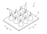
- FIG. 1 is a schematic perspective view of an example of a hollow protrusion having fine holes having apertures arranged therein, which is produced by the method for producing a hollow protrusion according to the present invention.
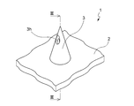
- FIG. 2 is a perspective view of the hollow protrusion according to one hollow protrusion of the plurality of hollow protrusions shown in FIG.
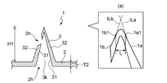
- FIG. 3 is a cross-sectional view taken along line III-III shown in FIG.
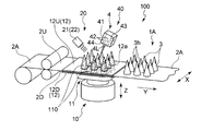
- FIG. 4 is a view showing an entire configuration of a manufacturing apparatus of a preferred embodiment for manufacturing the hollow protrusion shown in FIG.
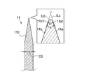
- FIG. 5 is an explanatory view showing a method of measuring the convex tip diameter and the tip angle of the convex portion.
- FIG. 6 (a) to 6 (e) are diagrams for explaining a manufacturing method of manufacturing a hollow projection having a fine hollow projection having an opening using the manufacturing apparatus shown in FIG.
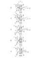
- FIG. 7 is a view for explaining the manufacturing method of another embodiment for manufacturing the hollow projection shown in FIG.
- Patent Document 2 Since the manufacturing method described in Patent Document 2 is manufactured by injection molding, temperature deviations or deformation of the mold due to wear tends to occur between the mold of the recess and the mold of the convex used, and the shape of the microneedle It is difficult to precisely manufacture the drug, and it is difficult to stably supply the agent to the inside of the skin through the opening. Further, according to the manufacturing method described in Patent Document 2, after forming a hollow microneedle, laser drilling is performed through the hollow microneedle to form a hole. As a result, burrs tend to form around the opening on the outer surface of the microneedle, which may make it difficult to puncture the skin.
- the present invention relates to a method and an apparatus for manufacturing a micro hollow protrusion having an opening, which can accurately manufacture the shape of a fine hollow projection and in which burrs are not easily formed around the opening on the outer surface of the hollow projection. .
- the present invention relates to a fine hollow protrusion having an opening that is easy to puncture the skin.
- FIG. 1 shows a perspective view of the hollow protrusion 1 of a preferred embodiment of the hollow protrusion according to the present invention.
- the hollow protrusion 1 includes a fine hollow protrusion 3 having an opening 3 h on the tip side and a flat base member 2.
- the hollow protrusion 1 has a configuration in which a plurality of hollow protrusions 3 project from the base member 2.
- FIG. 2 is a perspective view of the hollow protrusion 1 focusing on one hollow protrusion 3 among the arranged hollow protrusions 3 of the hollow protrusion 1, and FIG. 3 is shown in FIG. 2. It is a III-III line sectional view.
- the hollow protrusion 1 has an opening 3 h which is a through hole in the hollow protrusion 3.
- the hollow protrusion 1 has a base side opening 2 h at a position corresponding to each hollow protrusion 3 in the base member 2.
- a space 3 k is formed extending from the base side opening 2 h of the base member 2 to the opening 3 h on the tip side through the inside of each hollow projection 3. . Therefore, the opening 3 h penetrates the space 3 k inside the hollow protrusion 3.
- the space 3 k inside each hollow protrusion 3 is formed in a shape corresponding to the outer shape of the hollow protrusion 3, and the hollow protrusion 1 shown in FIG.
- the hollow projection 3 has the outer shape of the conical hollow protrusion 3. It is formed in a corresponding conical shape.
- the hollow projection 3 may have a truncated cone shape, a cylindrical shape, a prismatic shape, a pyramid shape, a truncated pyramid shape, or the like, in addition to the conical shape.
- the hole 3 h is a through hole formed at a position shifted from the center of the tip of the hollow protrusion 3 as shown in FIG. 2. As described above, when the hole 3 h is formed at a position shifted from the center of the tip of the hollow protrusion 3, the hole 3 h is unlikely to be crushed when the hollow protrusion 3 of the hollow protrusion 1 is punctured into the skin. The agent can be stably supplied from the hollow protrusion 1 to the inside of the skin through the openings 3 h.
- each hollow projection 3 When each hollow projection 3 is used as a microneedle, the projection height H1 of the hollow projection 3 is extended to the horn layer at the shallowest position and to the dermis at the deepest position.
- Reference is preferably 0.01 mm or more, more preferably 0.02 mm or more, and preferably 10 mm or less, more preferably 5 mm or less, and specifically preferably 0.01 mm to 10 mm. Or less, more preferably 0.02 mm or more and 5 mm or less.
- the tip diameter L of each hollow projection 3 is preferably 1 ⁇ m or more, more preferably 5 ⁇ m. It is the above, preferably 500 ⁇ m or less, more preferably 300 ⁇ m or less, specifically preferably 1 ⁇ m or more and 500 ⁇ m or less, and more preferably 5 ⁇ m or more and 300 ⁇ m or less.
- the tip diameter L of the hollow protrusion 1 is the length at the widest position at the tip of the hollow protrusion 3. Within this range, there is almost no pain when the hollow projection device 1 is pierced into the skin. The tip diameter L is measured as follows.
- the tip of the hollow projection 3 is observed with a predetermined magnification as shown in FIG. 3A using a scanning electron microscope (SEM) or a microscope.
- SEM scanning electron microscope
- the virtual straight line ILa is extended along the straight portion at one side 1a of the two sides 1a and 1b forming the outer surface 32, and the straight portion at the other side 1b Extend the virtual straight line ILb along.
- a portion where one side 1a is separated from the imaginary straight line ILa is determined as a first end point 1a1
- a portion where the other side 1b is separated from the imaginary straight line ILb is determined as a second end point 1b1.
- the length L of the straight line connecting the first tip point 1a1 and the second tip point 1b1 thus determined is measured using a scanning electron microscope (SEM) or a microscope, and the length of the straight line is measured. Is the tip diameter of the hollow protrusion 3.
- Aperture 3h is open area S1 of the inner surface 31 of the hollow projections 3, good properly is 0.7 [mu] m 2 or more, further preferably 20 [mu] m 2 or more, and preferably not 200000Myuemu 2 or less, more preferably 70000Myuemu 2 or less, particularly preferably not 0.7 [mu] m 2 or more 200000Myuemu 2 or less, still more preferably 20 [mu] m 2 or more 70000Myuemu 2 or less.
- the hole 3 h is formed such that the hole area on the outer surface 32 side of the hollow protrusion 3 is larger than the hole area S 1 on the inner surface 31 side of the hollow protrusion 3. That is, in the hole 3 h, the inner diameter on the outer surface 32 side of the hollow protrusion 3 is formed larger than the inner diameter on the inner surface 31 side of the hollow protrusion 3.
- the inner diameter on the inner surface 31 side is the diameter at the widest position in the opening 3 h formed on the inner surface 31, and the inner diameter on the outer surface 32 side is the largest diameter at the opening 3 h formed on the outer surface 32. It is a diameter.
- the inner diameter on the inner surface 31 side of the hole 3h is preferably 1 ⁇ m or more, more preferably 5 ⁇ m or more, from the viewpoint of stably supplying the agent to the inside of the skin through the hole 3h of the hollow projection 3.
- the inner diameter of the hole 3h on the outer surface 32 side is preferably 1.1 times or more, more preferably 1.2 times or more, and preferably 15 times the inner diameter on the inner surface 31 side.
- the inner diameter of the openings 3 h gradually increases from the inner surface 31 to the outer surface 32 of the hollow projection 3. It is preferable to increase.
- the opening area S2 at the lower surface of the base member 2 opposite to the upper surface on which the hollow projection 3 is disposed is preferably 0.007 mm 2 or more, more preferably 0.03 mm 2. or more, and preferably not 20 mm 2 or less, further preferably 7mm 2 or less, particularly preferably not 0.007 mm 2 or more 20 mm 2 or less, more preferably 0.03 mm 2 or more 7mm 2 or less.
- the nine hollow protrusions 3 arranged on the upper surface of the sheet-like base member 2 preferably have a uniform center-to-center distance in the first direction Y and a uniform center-to-center distance in the second direction X, It is preferable that the center-to-center distance in one direction Y and the center-to-center distance in the second direction X be the same distance.
- the center-to-center distance in the first direction Y of the hollow projection 3 is preferably 0.01 mm or more, more preferably 0.05 mm or more, and preferably 10 mm or less, more preferably 5 mm or less Specifically, it is preferably 0.01 mm or more and 10 mm or less, and more preferably 0.05 mm or more and 5 mm or less.
- the center-to-center distance in the second direction X of the hollow projection 3 is preferably 0.01 mm or more, more preferably 0.05 mm or more, and preferably 10 mm or less, more preferably 5 mm or less. Specifically, it is preferably 0.01 mm or more and 10 mm or less, and more preferably 0.05 mm or more and 5 mm or less.
- each hollow projection 3 of the hollow projection 1 is very small, but for convenience of explanation, each hollow projection 3 of the hollow projection 1 is drawn very large in FIG. 4. ing.
- the manufacturing apparatus 100 has a protrusion forming portion 10 including a convex portion 11 for forming the hollow protrusion 3 in the base sheet 2A, and an opening 3 h penetrating the hollow protrusion 3. And an aperture forming portion 40 comprising non-contacting aperture means for forming.
- the manufacturing apparatus 100 also includes a cooling unit 20.
- the manufacturing apparatus 100 inserts the convex portion 11 from the one surface 2D side of the base sheet 2A to form the non-penetrating hollow projection 3 projecting from the other surface 2U side of the base sheet 2A, and thereafter, the base An opening 3h which is a through hole is formed in the non-penetrating hollow projection 3 by the opening means from the other surface 2U side of the material sheet 2A.
- the direction in which the base sheet 2A is transported is the Y direction
- the direction orthogonal to the transport direction and the second direction in the base sheet 2A that is transported in the X direction
- the thickness direction of the base sheet 2A that is transported Will be described as the Z direction.
- the belt-like base sheet 2A is unrolled from the raw material roll of the base sheet 2A formed to contain the thermoplastic resin Transport in direction Y. And when base material sheet 2A is sent to a predetermined position, conveyance of base material sheet 2A is stopped. As described above, in the method of manufacturing the hollow protrusion 1, the belt-like base sheet 2 ⁇ / b> A is intermittently transported.
- the base sheet 2A is a sheet to be the base member 2 of the hollow protrusion 1 to be manufactured, and contains a thermoplastic resin.
- the base sheet 2A is mainly composed of a thermoplastic resin, that is, preferably contains 50% by mass or more, and more preferably contains 90% by mass or more of the thermoplastic resin.
- a thermoplastic resin poly fatty acid ester, polycarbonate, polypropylene, polyethylene, polyester, polyamide, polyamide imide, polyether ether ketone, polyether imide, polystyrene, polyethylene terephthalates, polyvinyl chloride, nylon resin, acrylic resin etc.
- polyfatty acid esters are preferably used from the viewpoint of biodegradability.
- the base sheet 2A may be formed of a mixture containing hyaluronic acid, collagen, starch, cellulose and the like in addition to the thermoplastic resin.
- the thickness of the base sheet 2A is equal to the thickness T2 (see FIG. 3) of the base member 2 of the hollow protrusion 1.
- the convex portion 11 provided in the protrusion forming portion 10 is inserted from the one surface 2 D side of the belt-like base sheet 2 A to insert the base sheet 2 A
- a protrusion forming step is performed to form fine hollow protrusions 3 protruding from the other surface 2U side.
- the protrusion formation part 10 is provided with the convex part 11 for protrusion formation, as shown in FIG.
- the convex part 11 may or may not be provided with a heating means (not shown)
- the manufacturing apparatus 100 is provided with a heating means (not shown).
- other heating means may not be provided in addition to the heating means of the convex portion 11.
- "does not provide any other heating means other than the heating means for the convex portion 11" not only refers to the case where other heating means are completely excluded, but also below the softening temperature of the base sheet 2A, It also means including the case of providing means for heating below the glass transition temperature. However, it is preferable not to include any other heating means.
- the convex portion 11 is a member provided with a convex portion 110 which is a portion to be pierced in the base sheet 2A, and the convex portion 11 is disposed on the disk-like base portion in the manufacturing apparatus 100. It has a structure. However, the present invention is not limited to this, and it may be a convex portion made of only the convex 110, or may be the convex 11 in which a plurality of convexs 110 are disposed on a trapezoidal support.
- the convex portion 11 has the convex 110 corresponding to the number and arrangement of the hollow projections 3 of the hollow projection 1 to be manufactured, and the approximate outer shape of each hollow projection 3, and nine in the manufacturing apparatus 100. There are nine conical convex shapes 110 corresponding to the conical hollow projections 3 of FIG.
- the convex 110 is formed in a conical shape with nine sharp tips, and the tips are disposed upward in the thickness direction Z.
- the convex portion 11 is disposed on the one surface 2D side (lower surface side) of the base sheet 2A at a predetermined interval below the thickness direction Z from the one surface 2D.
- the convex part 11 is movable up and down in the thickness direction Z by an electric actuator (not shown).
- the tip end of the convex mold 110 of the convex part 11 is configured to be able to abut from the one surface 2D side of the base sheet 2A.
- the heating means of the convex part 11 is an ultrasonic vibration apparatus. It is preferable that the operation of the ultrasonic vibration of the convex part 11 is performed from immediately before the convex part 11 abuts on the base sheet 2A to immediately before the cooling process described later, which is the next process.
- the control of the heating condition of the heating means provided in the convex part 11 such as the operation of the convex part 11 and the operation of the heating means of the convex part 11 is controlled by the control means (not shown) provided in the manufacturing apparatus 100 There is.
- the ultrasonic vibration of the convex portion 11 by the ultrasonic vibration device has a frequency of preferably 10 kHz or more, more preferably 15 kHz or more, and preferably 50 kHz or less from the viewpoint of the formation of the hollow protrusion 3. More preferably, it is 40 kHz or less, specifically, preferably 10 kHz or more and 50 kHz or less, and still more preferably 15 kHz or more and 40 kHz or less.
- the ultrasonic vibration of the convex portion 11 preferably has an amplitude of 1 ⁇ m or more, more preferably 5 ⁇ m or more, and preferably 60 ⁇ m or less, from the viewpoint of the formation of the hollow protrusion 3 and is more preferable. Is 50 ⁇ m or less, specifically, preferably 1 ⁇ m or more and 60 ⁇ m or less, and more preferably 5 ⁇ m or more and 50 ⁇ m or less.
- the shape of the tip end side of the convex portion 11 may be a shape corresponding to the outer shape of the hollow protrusion 3 of the hollow protrusion 1 to be manufactured.
- the height of the convex 110 of the convex portion 11 is preferably equal to or slightly higher than the height H1 (see FIG. 3) of the hollow projection 3 of the hollow projection 1 to be manufactured. Is preferably 0.01 mm or more, more preferably 0.02 mm or more, and preferably 30 mm or less, more preferably 20 mm or less, and specifically preferably 0.01 mm or more and 30 mm or less, and more preferably Preferably they are 0.02 mm or more and 20 mm or less.
- the tip diameter D1 (see FIG.
- the convex 110 of the convex part 11 is preferably 0.001 mm or more, more preferably 0.005 mm or more, and preferably 1 mm or less, more preferably Specifically, it is preferably 0.001 mm or more and 1 mm or less, and more preferably 0.005 mm or more and 0.5 mm or less.
- the tip diameter D1 of the convex mold 110 of the convex part 11 is measured as follows.
- the root diameter D2 of the convex mold 110 of the convex part 11 is preferably 0.1 mm or more, more preferably 0.2 mm or more, and preferably 5 mm or less, more preferably 3 mm or less, Specifically, it is preferably 0.1 mm or more and 5 mm or less, and more preferably 0.2 mm or more and 3 mm or less.
- the tip angle ⁇ of the convex 110 of the convex portion 11 is preferably 1 degree or more, more preferably 5 degrees or more, from the viewpoint of obtaining sufficient strength easily.
- the tip angle ⁇ is preferably 60 degrees or less, more preferably 45 degrees or less, from the viewpoint of obtaining the hollow projection 3 having an appropriate angle, and more specifically, preferably 1 to 60 degrees. Or less, more preferably 5 degrees or more and 45 degrees or less.
- the tip angle ⁇ of the convex portion 11 is measured as follows.
- a portion where one side 11a is separated from the imaginary straight line ILc is determined as a first end point 11a1
- a portion where the other side 11b is separated from the imaginary straight line ILd is determined as a second end point 11b1.
- the length D1 of the straight line connecting the first tip point 11a1 and the second tip point 11b1 thus obtained is measured using a scanning electron microscope or a microscope, and the length of the straight line measured is a convex.
- the tip diameter of the mold 110 is used.
- the convex portion 11 is formed of a high strength material that is not easily broken.
- Examples of the material of the convex portion 11 include metals such as steel, stainless steel, aluminum, aluminum alloy, nickel, nickel alloy, cobalt, cobalt alloy, copper, copper alloy, beryllium copper, beryllium copper alloy, and ceramics. .
- the protrusion forming portion 10 has a first opening plate 12U as a deflection suppressing means on the other surface 2U side (upper surface side) of the base sheet 2A, and one side 2D side of the base sheet 2A.
- a second opening plate 12D as a deflection suppressing means is provided on the (lower surface side).
- Both opening plates 12U and 12D are formed of plate-like members extending in parallel to the transport direction Y. The both opening plates 12U and 12D sandwich the base sheet 2A in the area other than the opening 12a.
- Both opening plates 12U and 12D are formed with an opening area larger than the cross sectional area of each convex 110 so that a plurality of each convex 110 in the convex part 11 can be inserted through one opening 12a. Although it may be, in the manufacturing apparatus 100, as shown in FIG.4 and FIG.6, it forms so that one convex 110 may be penetrated with respect to one opening 12a.
- the openings 12a of the first opening plate 12U are disposed concentrically with the openings 12a of the second opening plate 12D. Therefore, the openings 12a of the pair of first opening plates 12U sandwiching the base sheet 2A and the openings 12a of the second opening plate 12D overlap in the thickness direction.
- Both opening plates 12U and 12D are movable in the direction of contact with and away from the base sheet 2A.
- the opening plates 12U and 12D can be moved up and down in the thickness direction Z by electric actuators (not shown). Control of the operation of each of the aperture plates 12U and 12D is controlled by control means (not shown) provided in the manufacturing apparatus 100.
- both the opening plates 12U and 12D are movable in the direction of contact with and away from the base sheet 2A, but the second opening plate 12D is in contact with the base sheet 2A. It does not have to be movable in the direction away from the direction.
- the material forming the support member 12 may be the same material as the material of the respective convex portions 11, or may be formed of a synthetic resin or the like.
- the protrusion is formed in a state in which the base sheet 2A is held between the first opening plate 12U and the second opening plate 12D.
- the formation process is to be performed.
- the convex 110 is allowed to pass through the opening 12a of the second opening plate 12D from the one surface 2D side of the base sheet 2A, and as shown in FIG.
- the mold 110 while causing the mold 110 to express ultrasonic vibration in advance, the convex portion 11 is then brought into contact with one surface 2D of the base sheet 2A. This softens the contact portion TP.
- the convex 110 is lifted from the one surface 2D side to the other surface 2U side of the base sheet 2A while the contact portion TP is softened.
- the convex 110 is inserted into the base sheet 2A while suppressing the bending of the base sheet 2A by the first opening plate 12U disposed on the other surface 2U side.
- the fine non-penetrating hollow projection part 3 which protrudes from the other surface 2U side of the base material sheet 2A is formed.
- the heating temperature of the base sheet 2A by the heating of the convex portion 11 is preferably not less than the glass transition temperature of the base sheet 2A used and less than the melting temperature from the viewpoint of the formation of the hollow projection 3 and particularly the softening temperature
- the temperature is preferably above the melting temperature.
- the heating temperature is preferably 30 ° C. or more, more preferably 40 ° C. or more, and preferably 300 ° C. or less, more preferably 250 ° C. or less, and specifically preferably 30 C. to 300.degree. C., more preferably 40.degree. C. to 250.degree.
- the base material sheet 2A using an ultrasonic vibration apparatus when heating the base material sheet 2A using an ultrasonic vibration apparatus, it is applied as a temperature range of the part of the base material sheet 2A in contact with the convex 110.
- the heating temperature of the convex portion 11 when heating the substrate sheet 2A using a heater device instead of the ultrasonic vibration device, the heating temperature of the convex portion 11 may be adjusted in the above-mentioned range.
- the measurement method of the glass transition temperature (Tg) is measured by the following method, and the measurement method of the softening temperature is performed in accordance with JIS K-7196 "Method of testing softening temperature by thermomechanical analysis of thermoplastic plastic film and sheet". .
- the calorific value is measured using a DSC meter to determine the glass transition temperature.
- the measuring device uses a differential scanning calorimeter (Diamond DSC) manufactured by Perkin Elmer. Collect 10 mg of test pieces from the base sheet. The measurement conditions are maintained at 20 ° C. for 5 minutes, and then the temperature is raised from 20 ° C. to 320 ° C. at 5 ° C./minute to obtain DSC curves of the horizontal axis temperature and the vertical axis heat amount. Then, the glass transition temperature Tg is determined from this DSC curve.
- said "glass transition temperature (Tg) of a base material sheet” means the glass transition temperature (Tg) of the constituent resin of a base material sheet, and when two or more kinds of the constituent resin exist, those plural kinds of glass transition When the temperatures (Tg) are different from each other, the heating temperature of the substrate sheet by the heating means is preferably at least the lowest glass transition temperature (Tg) among the plurality of glass transition temperatures (Tg), It is more preferable that it is more than the highest glass transition temperature (Tg) among the glass transition temperatures (Tg) of the above.
- the “softening temperature of the base sheet” is also the same as the glass transition temperature (Tg), that is, when there are a plurality of types of constituent resins of the base sheet, the softening temperatures of the plurality of types are different from each other
- the heating temperature of the substrate sheet by the heating means is preferably at least the lowest softening temperature among at least the plurality of softening temperatures, and more preferably at least the highest softening temperature among the plurality of softening temperatures.
- fusing point differs, it is preferable that the heating temperature of the base material sheet by the said heating means is less than the lowest melting point among these melting points. .
- the resin is excessively heated and softened, and if too fast, the heat softening becomes insufficient, so that the hollow projection 3 is efficiently formed.
- a 0.1 mm / sec or more preferably 1 mm / sec or more, and preferably 1000 mm / sec or less, more preferably 800 mm / sec or less, and specifically preferably 0 1 mm / sec or more and 1000 mm / sec or less, more preferably 1 mm / sec or more and 800 mm / sec or less.
- the softening time which is the time until the cooling process of the next process is performed while stopping the rising of the convex part 11 in the heated state and inserting the convex part 11 into the hollow projection 3, is too long although it is excessive heating, it is preferably 0 seconds or more, more preferably 0.1 seconds or more, and preferably 10 seconds or less, more preferably 5 seconds or less, from the viewpoint of compensating for the insufficient heating. Preferably, it is 0 seconds or more and 10 seconds or less, and more preferably 0.1 seconds or more and 5 seconds or less.
- the insertion height of the convex part 11 to be pierced into the base sheet 2A is preferably 0.01 mm or more, more preferably 0.02 mm or more, from the viewpoint of efficiently forming the hollow projection 3, and preferably Is 10 mm or less, more preferably 5 mm or less, specifically, preferably 0.01 mm or more and 10 mm or less, and further preferably 0.02 mm or more and 5 mm or less.
- “insertion height” refers to the apex of the convex 110 and the other surface 2U of the base sheet 2A (upper surface in a state where the convex 110 of the convex part 11 is inserted most into the base sheet 2A).
- the insertion height in the protrusion forming step means the other surface in a state in which the convex 110 is pierced most deeply in the protrusion forming step and the convex 110 comes out from the other surface 2U of the base sheet 2A.
- the distance from 2U to the apex of the convex 110 measured in the vertical direction.
- a cooling step of cooling the hollow protrusion 3 is performed using the cold air blower 21 provided in the cooling unit 20.
- the air outlet 22 for blowing cold air is disposed on the other surface 2U side (upper surface side) of the base sheet 2A, and cold air is blown from the air outlet 22 and non-penetrating The hollow projection 3 is cooled.
- the cold air blower covers the other surface 2U (upper surface side) and the entire surface 2D (lower surface side) of the belt-like base sheet 2A to be transported in a hollow shape, and the inside of the cold air blower is
- the material sheet 2A may be conveyed in the conveyance direction (Y direction), and the air vent 22 for blowing cold air may be provided in the hollow, for example.
- the control of the cooling temperature and the cooling time of the cold air blower 21 is controlled by a control means (not shown) provided in the manufacturing apparatus 100.
- cooling is performed to cool the non-through hollow protrusion 3 in a state where the convex part 11 is inserted into the non-through hollow protrusion 3. It is supposed to carry out the process.
- the cooling step the movement of the convex portion 11 in the thickness direction (Z direction) by the electric actuator (not shown) is stopped, and the convex 110 of the convex portion 11 is pierced into the non-penetrating hollow projection 3.
- cool air is blown from the air outlet 22 disposed on the other surface 2U side (upper surface side) of the base sheet 2A, and cooling is performed while the convex 110 is inserted into the non-penetrating hollow protrusion 3 Do.
- the ultrasonic vibration of the convex portion 11 by the ultrasonic device may be in a continuous state or in a stopped state, but the shape of the non-penetrating hollow projection 3 is not deformed excessively and is constant It is preferable to be stopped from the viewpoint of keeping
- the temperature of the cold air to be blown is preferably ⁇ 50 ° C. or higher, more preferably ⁇ 40 ° C. or higher, and preferably 26 ° C. or lower, more preferably 10, from the viewpoint of formation of the non-penetrating hollow projections 3. C. or less, specifically, preferably -50.degree. C. or more and 26.degree. C. or less, and more preferably -40.degree. C. or more and 10.degree.
- the cooling time for blowing and cooling cold air is preferably 0.01 seconds or more, more preferably 0.5 seconds or more, and preferably 60 seconds or less, from the viewpoint of compatibility between formability and processing time. More preferably, it is 30 seconds or less, and specifically, it is preferably 0.01 seconds or more and 60 seconds or less, and more preferably 0.5 seconds or more and 30 seconds or less.
- the heating means of the convex part 11 is ultrasonic vibration like the manufacturing apparatus 100, it is not necessary to necessarily provide the cold-air blower 21, and it cools by cutting off the vibration of an ultrasonic vibration apparatus. It can also be done. From this point of view, it is preferable to use ultrasonic vibration as the heating means, since the apparatus can be simplified and the hollow projection 1 can be easily manufactured at high speed. Further, in the portion of the base sheet 2A which is not in contact with the convex portion 11, heat is less likely to be transmitted, and cooling is efficiently performed by turning off the application of the ultrasonic vibration, so that deformation occurs except for the molded portion. It has the advantage of being difficult.
- the hole forming step of forming the hole 3 h is performed.
- the non-penetrating hollow protrusion 3 is subjected to electromagnetic waves or the like using the non-contact type aperture means provided in the aperture forming portion 40. Hot air is irradiated to form an opening 3 h which is a through hole in the non-penetrating hollow protrusion 3.
- the hole forming portion 40 is provided with non-contact type hole opening means on the other surface 2U side of the base sheet 2A.
- non-contact type opening means include processing devices using a heat source such as a laser device for emitting laser light, a hot air emitting device for emitting hot air, a halogen lamp emitting device for emitting infrared light, etc.
- the laser device 4 is used from the viewpoint of being able to perform the light collecting property necessary for the fine processing and the energy control with high accuracy.
- the laser apparatus 4 has the irradiation head 41 which is a galvano scanner which scans 4 L of laser beams freely, as shown in FIG.
- the irradiation head 41 is disposed on the other surface 2U side (upper surface side) of the base sheet 2A at a certain distance above the other surface 2U in the thickness direction Z.
- the laser beam 4L is irradiated from the irradiation head 41 disposed on the other surface 2U side (upper surface side) of the base sheet 2A to the non-penetrating hollow projections 3 to form the openings 3h in the hollow projections 3
- it is easy to form the openings 3 h at arbitrary positions of the hollow projection 3 it is easy to arbitrarily control the position on the skin surface to which the liquid agent or the like is to be supplied.
- the irradiation head 41 has a lens 43 for condensing the irradiated laser beam 4L, and two mirrors 42 and a protective lens 44 for freely scanning the collected laser beam 4L.
- the protective lens 44 may or may not be provided, but is preferably provided in order to prevent dust and dirt from entering the optical system.
- the mirror 42 is attached to the motor shaft.
- the mirror 42 has a mechanism for moving the irradiation point of the laser beam 4L striking the hollow protrusion 3 on the base sheet 2A in the transport direction Y of the base sheet 2A, in the direction X orthogonal to the transport direction of the base sheet 2A.
- a mechanism for moving is provided so that the laser beam 4L can be freely scanned.
- the lens 43 is movable in the direction of the optical axis, and condenses the laser beam 4L to make the spot diameter of the irradiation point of the laser beam 4L striking the hollow projection 3 constant, and the irradiation of the laser beam 4L.
- a mechanism or the like for moving a point in the thickness direction (Z direction) of the base sheet 2A is provided.
- the irradiation head 41 having the mirror 42 and the lens 43 can adjust the irradiation point of the laser beam 4L in three dimensions including the X direction, the Y direction and the Z direction.
- the laser beam 4L may be a CO 2 laser, an excimer laser, an argon laser, a YAG laser, an LD laser ( It is preferable to use a semiconductor laser), a YVO 4 laser, a fiber laser or the like.
- the hollow protrusion 3 is cooled while the convex part 11 is inserted into the non-penetrating hollow protrusion 3.
- the non-penetrating hollow projection 3 is irradiated with the laser beam 4L from the irradiation head 41 to form an opening 3h.
- the laser light 4 L is irradiated to form the opening 3 h in a state where the convex portion 11 is inserted into the non-penetrating hollow projection 3
- the periphery of the opening 3 h on the inner surface 31 of the hollow projection 3 is formed. It is difficult for burrs to be formed, and the agent can be stably supplied to the inside of the skin.
- the laser beam 4L is irradiated to form the opening 3h in a state where the convex portion 11 is inserted into the inside of the non-penetrating hollow projection portion 3, the hollow projection portion 3 on the side irradiated with the laser light 4L. It is difficult to damage the inner surface 31 of the side wall opposite to the side wall, and the agent can be stably supplied to the inside of the skin.
- the opening 3 h may be formed at the tip of the hollow projection 3, but it is difficult to damage the tip of the hollow projection 3 and from the viewpoint of puncturing the skin easily, in the opening forming step, the non-penetrating hollow projection It is preferable to form the opening 3 h by irradiating the laser light 4 L to a position shifted from the center of the tip portion 3. From the viewpoint of forming the opening 3h by irradiating the side wall of the hollow protrusion 3 with the laser light 4L with a small irradiation energy, and from the viewpoint of maintaining the strength around the opening 3h formed by suppressing the influence of the irradiation energy of the laser light 4L.
- the laser beam 4L is inclined with respect to the insertion direction ILe of the convex 110 of the convex portion 11, as shown in FIG. 6C. It is preferable to form the opening 3 h by irradiating the non-penetrating hollow projection 3.
- the angle ⁇ between the insertion direction ILe of the convex 110 and the inclined direction ILf of the laser beam 4L is preferably 5 degrees or more, more preferably 10 degrees or more.
- the angle is preferably 15 degrees or more, more preferably 85 degrees or less, still more preferably 80 degrees or less, and particularly preferably 75 degrees or less.
- the irradiation time of the laser beam 4L is preferably 0.001 ms or more, more preferably 0.005 ms or more, and preferably 5 ms or less, and 3 ms or less More preferably, it is preferably 0.001 ms or more and 5 ms or less, and more preferably 0.005 ms or more and 3 ms or less.
- the laser output of the laser beam 4L is preferably 0.5 W or more, more preferably 1 W or more, and preferably 100 W or less, 50 W or less. More preferably, it is preferably 0.5 W or more and 100 W or less, and more preferably 1 W or more and 50 W or less.
- the hole 3 h is formed in the non-penetrating hollow protrusion 3, and the hollow protrusion is formed. Stop the cooling of part 3.
- the protrusion 11 is removed from the inside of the hollow protrusion 3 in which the opening 3 h is formed to form a hollow protrusion 3 having a hollow inside.
- the convex mold portion 11 is moved downward in the thickness direction (Z direction) by an electric actuator (not shown), and the convex mold 110 is inserted from the state where the convex mold 110 is pierced into each hollow protrusion 3.
- the second opening plate 12D is used as a deflection suppressing means for suppressing the deflection of the base sheet 2A when removing the convex portion 11 from the inside of the hollow projection 3, the convex 110 is a hollow projection It is easy to pull out from inside of 3.
- a precursor 1 ⁇ / b> A of the hollow protrusion 1 can be manufactured in which nine hollow protrusions 3 are arranged on the other surface 2 U (upper surface) of the base sheet 2 ⁇ / b> A.
- the precursor 1A of the hollow protrusion 1 is manufactured, the first opening plate 12U and the second opening plate 12D are separated from the base sheet 2A, and the base sheet 2A is released from the sandwiching state.
- the precursor 1A of the hollow protrusion 1 formed as described above is transported to the downstream side in the transport direction Y. Thereafter, in the cutting process, the hollow protrusion 1 having a sheet-like base member 2 and a plurality of hollow protrusions 3 as shown in FIG. 1 can be manufactured. By repeating the above steps, the hollow protrusion 1 can be manufactured continuously and efficiently.
- the hollow protrusion 1 manufactured as described above may be further formed into a predetermined shape in the subsequent steps, or may be formed into a desired shape before the step of inserting the convex portion 11 into the base sheet 2A. You may adjust in advance.
- the convex portion 11 is inserted from the one surface 2D side of the substrate sheet 2A to form the substrate sheet
- the shape of the fine hollow projections 3 having the openings 3 h can be manufactured with high precision, and burrs are not easily formed around the openings 3 h on the outer surface 32 of the hollow projections 3.
- the hollow protrusion 1 thus manufactured is easy to puncture the skin and can stably supply the agent to the inside of the skin.
- the non-through hollow protrusion 3 is inserted into the non-penetrating hollow protrusion 3 and cooled in the cooling step while the hollow protrusion 3 is cooled.
- the hole 3h penetrating to the hollow projection 3 is formed using the opening means, after the convex portion 11 is removed from the inside of the non-through hollow projection 3, the noncontact opening means is It may be used to form an opening 3 h penetrating the non-penetrating hollow projection 3.
- the base sheet 2A is held in a state in which the base sheet 2A is held between the first opening plate 12U and the second opening plate 12D.
- the convex 110 is made to pass through the opening 12a of the second opening plate 12D from the one surface 2D side, and the convex portion 11 is made the base sheet 2A while causing ultrasonic vibration to be generated in each convex 110 in advance by the ultrasonic vibration device. Abut on one side 2D. As a result, while softening the contact portion TP, the convex 110 is raised from the one surface 2D side to the other surface 2U side of the base sheet 2A, and the non-penetrating member protrudes from the other surface 2U side The hollow projection 3 is formed.
- the non-penetrating hollow projections 3 are cooled using the cold air blower 21 disposed on the other surface 2U side (upper surface side) of the base sheet 2A. Then, the convex portion 11 is removed from the inside of the non-penetrating hollow projection 3 to perform a release step of forming the hollow projection 3 having a hollow inside.
- the ultrasonic vibration of the convex portion 11 by the ultrasonic vibration device is stopped, and the convex portion 11 is moved downward in the thickness direction (Z direction) by the electric actuator (not shown), and the second aperture plate While suppressing the bending of the base sheet 2A by 12D, the convex 110 is removed from the inside of the hollow projection 3 to form the non-penetrating hollow projection 3.
- the holes 3h may be irradiated to form the holes 3h, and as shown in FIG. 7 (e), the hollow protrusion 3 in which the holes 3h are formed may be formed.
- the present invention further discloses a method of manufacturing a hollow projection having the following openings.
- a method of manufacturing a hollow protrusion having a fine hollow protrusion having an aperture comprising: A convex portion for forming a projection is inserted from one surface side of a base material sheet formed by including a thermoplastic resin to form a non-penetrating hollow projection which protrudes from the other surface side of the base material sheet Forming a projection, An opening forming step of forming an opening which is a through hole in the non-penetrating hollow projection using the noncontact opening means disposed on the other surface side of the base sheet Method of manufacturing tools.
- ⁇ 2> In the hole forming step, the method for manufacturing a hollow protrusion according to ⁇ 1>, wherein the hole is formed in a state in which the convex portion is inserted into the non-penetrating hollow protrusion.
- the hole forming step In the hole forming step, the method for manufacturing a hollow protrusion according to ⁇ 1> or ⁇ 2>, wherein the hole is formed at a position shifted from the center of the tip of the non-penetrating hollow protrusion.
- ⁇ 4> The method for producing a hollow projection according to any one of the above ⁇ 1> to ⁇ 3>, wherein a laser device is used as the noncontact opening means.
- the non-penetrating hollow projections are irradiated with laser light from the laser device from a direction inclined with respect to the insertion direction of the convex portion to form the holes.
- the angle between the insertion direction of the convex portion and the inclined direction of irradiating the laser beam is preferably 5 degrees or more, more preferably 10 degrees or more, and 15 degrees or more.
- Is particularly preferable and is preferably 85 degrees or less, more preferably 80 degrees or less, particularly preferably 75 degrees or less, and specifically 5 degrees or more and 85 degrees or less
- the method for producing a hollow projection according to ⁇ 5> preferably, 10 to 80 ° is more preferable, and 15 to 75 ° is particularly preferable.
- the convex portion has heating means, In the protrusion forming step, the method of manufacturing a hollow protrusion according to any one of ⁇ 1> to ⁇ 6>, wherein the base sheet is heated and softened by the heating unit.
- the time for heating and softening the substrate sheet by the heating means is preferably 0 seconds or more, more preferably 0.1 seconds or more, and preferably 10 seconds or less, more preferably 5 seconds or less.
- the method for producing a hollow protrusion according to ⁇ 7> which is preferably 0 seconds to 10 seconds, more preferably 0.1 seconds to 5 seconds.
- the convex portion has heating means, The method of manufacturing a hollow protrusion according to any one of ⁇ 1> to ⁇ 8>, wherein an ultrasonic vibration device is used as the heating unit.
- the insertion speed at which the convex portion is inserted into the base sheet is preferably 0.1 mm / sec or more, more preferably 1 mm / sec or more, and preferably 1000 mm / sec. Or less, more preferably 800 mm / sec or less, specifically preferably 0.1 mm / sec or more and 1000 mm / sec or less, and more preferably 1 mm / sec or more and 800 mm / sec or less.
- the method for producing a hollow protrusion according to any one of 1> to ⁇ 9>.
- ⁇ 11> The method for manufacturing a hollow protrusion according to any one of ⁇ 1> to ⁇ 10>, wherein a cooling step of cooling the non-penetrating hollow protrusion is performed after the protrusion forming step.
- a cooling step of cooling the non-penetrating hollow protrusion is performed after the protrusion forming step.
- the method for manufacturing a hollow protrusion according to ⁇ 11> wherein the non-through hollow protrusion is cooled in a state where the convex portion is inserted into the non-through hollow protrusion.
- ⁇ 13> The method for manufacturing a hollow protrusion according to ⁇ 11> or ⁇ 12>, wherein the hole forming step is performed while cooling the non-penetrating hollow protrusion in the cooling step or after the cooling step is completed.
- a manufacturing apparatus for manufacturing a hollow protrusion having a fine hollow protrusion having an aperture comprising: A protrusion forming portion provided with a convex portion for forming a protrusion disposed on one surface side of a substrate sheet formed by including a thermoplastic resin, and a noncontact type disposed on the other surface side of the substrate sheet And an aperture forming portion provided with the aperture means of The convex portion is pierced from one side of the base sheet to form a non-penetrating hollow projection which protrudes from the other side of the base sheet, and then from the other side of the base sheet
- ⁇ 15> The hollow protrusion according to ⁇ 14>, wherein the hole forming portion is configured to form the hole in a state in which the convex portion is inserted into the non-penetrating hollow protrusion. manufacturing device.
- ⁇ 16> The hollow protrusion according to ⁇ 14> or ⁇ 15>, wherein the hole forming portion is configured to form a hole at a position offset from the center of the tip of the non-penetrating hollow protrusion. manufacturing device.
- ⁇ 17> The apparatus for producing a hollow projection according to any one of the above ⁇ 14> to ⁇ 16>, wherein the noncontact opening means is a laser device.
- the hole forming portion irradiates the non-penetrating hollow protrusion with a laser beam from the laser device in a direction inclined with respect to the insertion direction of the convex portion to form the hole.
- the angle between the insertion direction of the convex portion and the inclined direction of irradiating the laser beam is preferably 5 degrees or more, more preferably 10 degrees or more, and 15 degrees or more.
- Is particularly preferable and is preferably 85 degrees or less, more preferably 80 degrees or less, particularly preferably 75 degrees or less, and specifically 5 degrees or more and 85 degrees or less
- the apparatus for manufacturing a hollow protrusion according to ⁇ 18> which is preferably 10 degrees to 80 degrees, more preferably 15 degrees to 75 degrees.
- the manufacturing apparatus of the hollow projection tool as described in said ⁇ 20> which has an ultrasonic vibration apparatus as said heating means.
- a cooling unit configured to cool the non-penetrating hollow protrusion is provided downstream of the protrusion forming portion in the conveyance direction of the base sheet.
- a hollow protrusion comprising fine hollow protrusions having apertures, comprising: The hole is a through hole disposed at a position offset from the center of the tip of the hollow protrusion, The hollow protrusion according to claim 1, wherein the hole has an inner diameter on the outer surface side of the hollow protrusion that is larger than an inner diameter on the inner surface side of the hollow protrusion.
- the inner diameter of the inner surface of the hole is preferably 1 ⁇ m or more, more preferably 5 ⁇ m or more, and preferably 500 ⁇ m or less, more preferably 300 ⁇ m or less, and specifically preferably 1 ⁇ m to 500 ⁇ m.
- the hollow protrusion according to ⁇ 25> or ⁇ 26> which is the following, and more preferably 5 ⁇ m to 300 ⁇ m.
- the inner diameter on the outer surface side of the hole is preferably 1.1 times or more, more preferably 1.2 times or more, and preferably 15 times or less, more preferably 10 times the inner diameter on the inner surface side. Any one of the above ⁇ 25> to ⁇ 27>, which is twice or less, specifically, preferably 1.1 or more and 15 or less, and more preferably 1.2 or more and 10 or less.
- Convex Part 11 Provided in Manufacturing Apparatus As the convex part 11, a part formed of SUS304, which is a stainless steel material, was prepared. The convex part 11 had one conical convex 110. The convex 110 has a height (height of the tapered portion) H2 of 2.5 mm, a tip diameter D1 of 15 ⁇ m, a root diameter D2 of 0.5 mm, and a tip angle of 11 degrees. there were.
- Base Material Sheet 2A As the base material sheet 2A, a 0.3 mm-thick band-like sheet of polylactic acid (PLA; Tg 55.8 ° C.) was prepared.
- PLA polylactic acid
- the non-penetrating hollow protrusions 3 were formed in the order shown in FIGS. 7 (a) to 7 (c).
- the frequency of the ultrasonic vibration of the convex portion 11 was 20 kHz, and the amplitude of the ultrasonic vibration was 40 ⁇ m.
- the insertion height of the convex portion 11 was 0.7 mm, and the insertion speed was 10 mm / sec.
- the softening time was 0.1 second and the cooling time was 0.5 second.
- the protrusion height H1 of the hollow protrusion 3 thus formed was 1 mm.
- Examples 1 to 3 After the non-penetrating hollow projections 3 were formed, the hollow projections 1 were manufactured in the order shown in FIGS. 7 (d) to 7 (e). Specifically, the position from the tip of the hollow protrusion 3 was 300 ⁇ m, the laser output of the laser beam 4L was 14 W, and the angle ⁇ between the insertion direction ILe and the inclined direction ILf was fixed at 30 degrees.
- the hollow projections according to Examples 1 to 3 are opened by changing the irradiation time of the laser beam 4L to 0.015 ms, 0.02 ms, and 0.04 ms, respectively, and irradiating the laser light 4 L to the hollow projection 3. Hole 3h was formed.
- Example 4 After the non-penetrating hollow projections 3 were formed, the hollow projections 1 were manufactured in the order shown in FIGS. 7 (d) to 7 (e). Specifically, the position from the tip of the hollow protrusion 3 was 300 ⁇ m, the irradiation time of the laser beam 4L was 0.02 ms, and the angle ⁇ between the insertion direction ILe and the inclined direction ILf was fixed at 30 degrees. In the hollow protrusion of Example 4, the laser output of the laser beam 4L was changed to 10 W, and the laser beam 4L was irradiated to the hollow protrusion 3 to form an aperture 3h.
- the hollow projections 1 were manufactured in the order shown in FIGS. 7 (d) to 7 (e). Specifically, the laser output of the laser beam 4L is 14 W, the irradiation time of the laser beam 4L is 0.02 ms, and the angle ⁇ between the insertion direction ILe and the inclined direction ILf is fixed at 30 degrees.
- the positions from the tip of the hollow projections 3 are changed to 200 ⁇ m, 500 ⁇ m, 700 ⁇ m, and 900 ⁇ m, respectively, and the hollow projections 3 are irradiated with the laser beam 4L. Formed 3h.
- the hollow projections 1 were manufactured in the order shown in FIGS. 7 (d) to 7 (e). Specifically, the position from the tip of the hollow protrusion 3 was fixed to 500 ⁇ m, the laser output of the laser beam 4L was fixed to 14 W, and the irradiation time of the laser beam 4 L was fixed to 0.02 ms. In the hollow protrusions according to Examples 9 to 10, the hollow protrusion 3 is irradiated with the laser beam 4L by changing the angle ⁇ between the insertion direction ILe and the inclined direction ILf to 15 degrees and 45 degrees, respectively. , 3 h of openings were formed.
- the hollow projections of Examples 1 to 10 have no burrs on the outer surface, and it can be expected that they can be punctured smoothly when puncturing the skin.
- the shape of the hollow projections and the shape of the openings were good. Therefore, according to the manufacturing method of manufacturing the hollow projections of Examples 1 to 10, it is possible to efficiently and continuously manufacture the hollow projections having good accuracy of the height of the hollow projections and the size of the holes. Can be expected.
- the shape of the fine hollow projection having the opening can be manufactured with high accuracy, and it is difficult to form burr around the opening on the outer surface of the hollow projection. Moreover, according to the micro hollow protrusion of the present invention, it is easy to puncture the skin.
Landscapes
- Engineering & Computer Science (AREA)
- Health & Medical Sciences (AREA)
- Mechanical Engineering (AREA)
- Life Sciences & Earth Sciences (AREA)
- General Health & Medical Sciences (AREA)
- Dermatology (AREA)
- Heart & Thoracic Surgery (AREA)
- Hematology (AREA)
- Anesthesiology (AREA)
- Animal Behavior & Ethology (AREA)
- Medical Informatics (AREA)
- Public Health (AREA)
- Veterinary Medicine (AREA)
- Biomedical Technology (AREA)
- Physics & Mathematics (AREA)
- Optics & Photonics (AREA)
- Plasma & Fusion (AREA)
- Forests & Forestry (AREA)
- Oral & Maxillofacial Surgery (AREA)
- Thermal Sciences (AREA)
- Media Introduction/Drainage Providing Device (AREA)
- Moulds For Moulding Plastics Or The Like (AREA)
Priority Applications (4)
| Application Number | Priority Date | Filing Date | Title |
|---|---|---|---|
| EP18855207.9A EP3682938B1 (en) | 2017-09-13 | 2018-06-14 | Method for manufacturing hollow needling implement, device for manufacturing hollow needling implement |
| US16/646,722 US11433224B2 (en) | 2017-09-13 | 2018-06-14 | Method for manufacturing hollow needling implement, device for manufacturing hollow needling implement, and hollow needling implement |
| KR1020207003996A KR102641593B1 (ko) | 2017-09-13 | 2018-06-14 | 중공 돌기구의 제조 방법, 중공 돌기구의 제조 장치 |
| CN201880055117.6A CN111050838B (zh) | 2017-09-13 | 2018-06-14 | 中空突起器具的制造方法和中空突起器具的制造装置 |
Applications Claiming Priority (2)
| Application Number | Priority Date | Filing Date | Title |
|---|---|---|---|
| JP2017-175950 | 2017-09-13 | ||
| JP2017175950A JP6965068B2 (ja) | 2017-09-13 | 2017-09-13 | 中空突起具の製造方法、中空突起具の製造装置、及び中空突起具 |
Publications (1)
| Publication Number | Publication Date |
|---|---|
| WO2019053977A1 true WO2019053977A1 (ja) | 2019-03-21 |
Family
ID=65723362
Family Applications (1)
| Application Number | Title | Priority Date | Filing Date |
|---|---|---|---|
| PCT/JP2018/022719 Ceased WO2019053977A1 (ja) | 2017-09-13 | 2018-06-14 | 中空突起具の製造方法、中空突起具の製造装置、及び中空突起具 |
Country Status (6)
| Country | Link |
|---|---|
| US (1) | US11433224B2 (enExample) |
| EP (1) | EP3682938B1 (enExample) |
| JP (1) | JP6965068B2 (enExample) |
| KR (1) | KR102641593B1 (enExample) |
| CN (1) | CN111050838B (enExample) |
| WO (1) | WO2019053977A1 (enExample) |
Cited By (1)
| Publication number | Priority date | Publication date | Assignee | Title |
|---|---|---|---|---|
| WO2024237204A1 (ja) * | 2023-05-12 | 2024-11-21 | Asti株式会社 | マイクロニードル製造方法とマイクロニードルとマイクロニードルユニット |
Families Citing this family (5)
| Publication number | Priority date | Publication date | Assignee | Title |
|---|---|---|---|---|
| JP7273651B2 (ja) * | 2019-08-07 | 2023-05-15 | 花王株式会社 | 中空突起具の製造方法 |
| JP2021142085A (ja) * | 2020-03-11 | 2021-09-24 | 花王株式会社 | 中空突起具の製造方法及び中空突起具 |
| JP7522006B2 (ja) * | 2020-10-29 | 2024-07-24 | 花王株式会社 | 中空突起具の製造方法 |
| DE112022002029T5 (de) * | 2021-06-09 | 2024-01-18 | Kao Corporation | Injektionsnadel |
| JP7786938B2 (ja) * | 2021-12-20 | 2025-12-16 | 花王株式会社 | 中空突起具の製造方法、及び中空突起具 |
Citations (9)
| Publication number | Priority date | Publication date | Assignee | Title |
|---|---|---|---|---|
| JPH07308383A (ja) * | 1994-05-19 | 1995-11-28 | Nippon Zeon Co Ltd | カテーテル |
| JP2002172169A (ja) * | 2000-12-07 | 2002-06-18 | Fanuc Ltd | マイクロ注射針 |
| JP2011072695A (ja) | 2009-10-01 | 2011-04-14 | Asti Corp | マイクロニードルアレイの製造方法とマイクロニードルアレイ構造体 |
| US20120041337A1 (en) | 2009-04-10 | 2012-02-16 | Ferguson Dennis E | Methods of making hollow microneedle arrays and articles and uses therefrom |
| JP2012532709A (ja) * | 2009-07-15 | 2012-12-20 | デバイオテック・ソシエテ・アノニム | 多チャンネル・マイクロニードル |
| WO2015125475A1 (ja) * | 2014-02-24 | 2015-08-27 | 凸版印刷株式会社 | 中空型針状体の製造方法および中空型針状体 |
| JP2017131397A (ja) * | 2016-01-27 | 2017-08-03 | 花王株式会社 | 微細中空突起具の製造方法 |
| US20170239855A1 (en) | 2014-10-17 | 2017-08-24 | Kao Corporation | Fine hollow protrusion manufacturing method |
| WO2017170816A1 (ja) * | 2016-03-31 | 2017-10-05 | 花王株式会社 | 微細中空突起具の製造方法、及び微細中空突起具 |
Family Cites Families (12)
| Publication number | Priority date | Publication date | Assignee | Title |
|---|---|---|---|---|
| US6312612B1 (en) * | 1999-06-09 | 2001-11-06 | The Procter & Gamble Company | Apparatus and method for manufacturing an intracutaneous microneedle array |
| DE10065188A1 (de) | 2000-12-23 | 2002-06-27 | Odin Gmbh Design Und Imagekonz | Pinwandsystem mit einer beliebig erweiterbaren Pinwandfläche |
| DE10065168A1 (de) * | 2000-12-23 | 2002-07-11 | Lohmann Therapie Syst Lts | Nadelpflaster mit vermindertem Infektionsrisiko |
| US7383687B2 (en) * | 2002-10-31 | 2008-06-10 | Sharp Kabushiki Kaisha | Regenerator method for manufacturing regenerator, system for manufacturing regenerator and stirling refrigerating machine |
| WO2005082593A1 (en) * | 2004-02-17 | 2005-09-09 | Avery Dennison Corporation | Method of making microneedles |
| WO2006057619A1 (en) * | 2004-11-26 | 2006-06-01 | Agency For Science, Technology And Research | Method and apparatus for forming microstructures |
| US20080097352A1 (en) * | 2006-09-12 | 2008-04-24 | Beck Patricia A | Methods of fabricating microneedles with bio-sensory functionality |
| JPWO2008062832A1 (ja) * | 2006-11-22 | 2010-03-04 | 凸版印刷株式会社 | マイクロニードルアレイ及びマイクロニードルアレイの製造方法 |
| US20090093775A1 (en) * | 2007-10-03 | 2009-04-09 | Raju Remesh S O Govinda | Microstructures |
| CN101297989B (zh) * | 2008-06-19 | 2010-06-23 | 上海交通大学 | 基于模压的中空微针批量制备方法 |
| WO2015009524A1 (en) * | 2013-07-16 | 2015-01-22 | 3M Innovative Properties Company | Hollow microneedle with beveled tip |
| JP6064012B1 (ja) | 2014-10-17 | 2017-01-18 | 花王株式会社 | 微細中空突起物の製造方法 |
-
2017
- 2017-09-13 JP JP2017175950A patent/JP6965068B2/ja active Active
-
2018
- 2018-06-14 US US16/646,722 patent/US11433224B2/en active Active
- 2018-06-14 EP EP18855207.9A patent/EP3682938B1/en active Active
- 2018-06-14 KR KR1020207003996A patent/KR102641593B1/ko active Active
- 2018-06-14 WO PCT/JP2018/022719 patent/WO2019053977A1/ja not_active Ceased
- 2018-06-14 CN CN201880055117.6A patent/CN111050838B/zh active Active
Patent Citations (10)
| Publication number | Priority date | Publication date | Assignee | Title |
|---|---|---|---|---|
| JPH07308383A (ja) * | 1994-05-19 | 1995-11-28 | Nippon Zeon Co Ltd | カテーテル |
| JP2002172169A (ja) * | 2000-12-07 | 2002-06-18 | Fanuc Ltd | マイクロ注射針 |
| US20120041337A1 (en) | 2009-04-10 | 2012-02-16 | Ferguson Dennis E | Methods of making hollow microneedle arrays and articles and uses therefrom |
| JP2012532709A (ja) * | 2009-07-15 | 2012-12-20 | デバイオテック・ソシエテ・アノニム | 多チャンネル・マイクロニードル |
| JP2011072695A (ja) | 2009-10-01 | 2011-04-14 | Asti Corp | マイクロニードルアレイの製造方法とマイクロニードルアレイ構造体 |
| WO2015125475A1 (ja) * | 2014-02-24 | 2015-08-27 | 凸版印刷株式会社 | 中空型針状体の製造方法および中空型針状体 |
| US20160354521A1 (en) | 2014-02-24 | 2016-12-08 | Toppan Printing Co., Ltd. | Method for manufacturing hollow needle-shaped body, and hollow needle-shaped body |
| US20170239855A1 (en) | 2014-10-17 | 2017-08-24 | Kao Corporation | Fine hollow protrusion manufacturing method |
| JP2017131397A (ja) * | 2016-01-27 | 2017-08-03 | 花王株式会社 | 微細中空突起具の製造方法 |
| WO2017170816A1 (ja) * | 2016-03-31 | 2017-10-05 | 花王株式会社 | 微細中空突起具の製造方法、及び微細中空突起具 |
Non-Patent Citations (1)
| Title |
|---|
| See also references of EP3682938A4 |
Cited By (1)
| Publication number | Priority date | Publication date | Assignee | Title |
|---|---|---|---|---|
| WO2024237204A1 (ja) * | 2023-05-12 | 2024-11-21 | Asti株式会社 | マイクロニードル製造方法とマイクロニードルとマイクロニードルユニット |
Also Published As
| Publication number | Publication date |
|---|---|
| EP3682938A1 (en) | 2020-07-22 |
| CN111050838B (zh) | 2022-03-04 |
| JP2019050927A (ja) | 2019-04-04 |
| JP6965068B2 (ja) | 2021-11-10 |
| KR20200053472A (ko) | 2020-05-18 |
| EP3682938A4 (en) | 2021-11-10 |
| EP3682938B1 (en) | 2025-08-06 |
| US20200269029A1 (en) | 2020-08-27 |
| CN111050838A (zh) | 2020-04-21 |
| US11433224B2 (en) | 2022-09-06 |
| KR102641593B1 (ko) | 2024-02-27 |
Similar Documents
| Publication | Publication Date | Title |
|---|---|---|
| WO2019053977A1 (ja) | 中空突起具の製造方法、中空突起具の製造装置、及び中空突起具 | |
| KR102021212B1 (ko) | 미세 중공 돌기물의 제조 방법 | |
| KR102428499B1 (ko) | 미세 중공 돌기구의 제조 방법 | |
| CN110709128A (zh) | 微细突起单元的制造方法和微细突起单元 | |
| JP7273651B2 (ja) | 中空突起具の製造方法 | |
| JP6561032B2 (ja) | 微細中空突起物の製造方法 | |
| JP6586329B2 (ja) | 微細中空突起物の製造方法 | |
| CN109069813B (zh) | 微细中空突起器具的制造方法及微细中空突起器具 | |
| JP6126658B2 (ja) | 微細中空突起物の製造方法 | |
| CN108883263B (zh) | 微细中空突起器具 | |
| JP6693790B2 (ja) | 開孔部を有する微細中空突起具の製造方法 | |
| JP6717638B2 (ja) | 開孔部を有する微細中空突起具の製造方法 | |
| JP6775095B2 (ja) | 微細中空突起具の製造方法 | |
| JP7522006B2 (ja) | 中空突起具の製造方法 | |
| JP2022072096A (ja) | 中空突起具の製造方法 | |
| JP2023091681A (ja) | 中空突起具の製造方法、及び中空突起具 | |
| JP2022011197A (ja) | 中空突起具の製造方法 |
Legal Events
| Date | Code | Title | Description |
|---|---|---|---|
| 121 | Ep: the epo has been informed by wipo that ep was designated in this application |
Ref document number: 18855207 Country of ref document: EP Kind code of ref document: A1 |
|
| NENP | Non-entry into the national phase |
Ref country code: DE |
|
| ENP | Entry into the national phase |
Ref document number: 2018855207 Country of ref document: EP Effective date: 20200414 |
|
| WWG | Wipo information: grant in national office |
Ref document number: 2018855207 Country of ref document: EP |