WO2019044768A1 - 熱処理システムおよび熱処理方法 - Google Patents
熱処理システムおよび熱処理方法 Download PDFInfo
- Publication number
- WO2019044768A1 WO2019044768A1 PCT/JP2018/031575 JP2018031575W WO2019044768A1 WO 2019044768 A1 WO2019044768 A1 WO 2019044768A1 JP 2018031575 W JP2018031575 W JP 2018031575W WO 2019044768 A1 WO2019044768 A1 WO 2019044768A1
- Authority
- WO
- WIPO (PCT)
- Prior art keywords
- work
- assembly
- jig
- heat treatment
- hand
- Prior art date
- Legal status (The legal status is an assumption and is not a legal conclusion. Google has not performed a legal analysis and makes no representation as to the accuracy of the status listed.)
- Ceased
Links
Images






Classifications
-
- C—CHEMISTRY; METALLURGY
- C21—METALLURGY OF IRON
- C21D—MODIFYING THE PHYSICAL STRUCTURE OF FERROUS METALS; GENERAL DEVICES FOR HEAT TREATMENT OF FERROUS OR NON-FERROUS METALS OR ALLOYS; MAKING METAL MALLEABLE, e.g. BY DECARBURISATION OR TEMPERING
- C21D1/00—General methods or devices for heat treatment, e.g. annealing, hardening, quenching or tempering
- C21D1/06—Surface hardening
-
- C—CHEMISTRY; METALLURGY
- C21—METALLURGY OF IRON
- C21D—MODIFYING THE PHYSICAL STRUCTURE OF FERROUS METALS; GENERAL DEVICES FOR HEAT TREATMENT OF FERROUS OR NON-FERROUS METALS OR ALLOYS; MAKING METAL MALLEABLE, e.g. BY DECARBURISATION OR TEMPERING
- C21D9/00—Heat treatment, e.g. annealing, hardening, quenching or tempering, adapted for particular articles; Furnaces therefor
- C21D9/40—Heat treatment, e.g. annealing, hardening, quenching or tempering, adapted for particular articles; Furnaces therefor for rings; for bearing races
-
- F—MECHANICAL ENGINEERING; LIGHTING; HEATING; WEAPONS; BLASTING
- F27—FURNACES; KILNS; OVENS; RETORTS
- F27D—DETAILS OR ACCESSORIES OF FURNACES, KILNS, OVENS OR RETORTS, IN SO FAR AS THEY ARE OF KINDS OCCURRING IN MORE THAN ONE KIND OF FURNACE
- F27D19/00—Arrangements of controlling devices
-
- C—CHEMISTRY; METALLURGY
- C21—METALLURGY OF IRON
- C21D—MODIFYING THE PHYSICAL STRUCTURE OF FERROUS METALS; GENERAL DEVICES FOR HEAT TREATMENT OF FERROUS OR NON-FERROUS METALS OR ALLOYS; MAKING METAL MALLEABLE, e.g. BY DECARBURISATION OR TEMPERING
- C21D1/00—General methods or devices for heat treatment, e.g. annealing, hardening, quenching or tempering
Definitions
- the present invention relates to a heat treatment system and a heat treatment method, and more particularly to a heat treatment system and a heat treatment method which are applied when performing a carburizing heat treatment on an annular work.
- a carburizing heat treatment may be carried out as a heat treatment for applying (for example, patent document 1).
- Patent Document 1 after assembling an assembly including an axial jig supporting a plurality of annular workpieces in a non-contact manner with each other and supporting the both ends of the jig, the assembly is heated.
- a chamber, a carburizing chamber, a cooling chamber and the like are continuously introduced into a continuous heat treatment furnace (carburizing heat treatment furnace).
- the carburizing heat treatment can be simultaneously performed on a plurality of annular works, and furthermore, the carburizing heat treatment can be accurately performed on each annular work.
- the above-mentioned operation error occurs even if the assembly assembly work and / or disassembly work is automated. It is also considered possible to reduce the frequency of occurrence of and to carry out the heat treatment process efficiently and at low cost.
- a jig made of a material that is difficult to thermally deform can not completely prevent thermal deformation, and if the frequency of jig replacement is increased, the cost reduction due to automation of the above-mentioned operation can be corrected. It will be offset by the increase in expenses.
- the present invention aims to make it possible to automate a heat treatment (carburizing heat treatment) process of simultaneously performing a carburizing heat treatment on a plurality of annular workpieces and to improve the productivity of the carburizing heat treatment process.
- the invention invented to achieve the above object comprises a heat treatment furnace having at least a carburizing chamber and a cooling chamber, and an assembling apparatus for assembling an assembly to be introduced into the heat treatment furnace, the assembly comprising an annular ring to be heat treated.
- a heat treatment system including a shaft-like jig in which a plurality of workpieces are suspended and supported in a non-contact state with each other and a container in which both ends of the jig are supported.
- An assembly robot capable of repeatedly performing work attachment work in which an annular work is suspended one by one, and an assembly detection device for acquiring position information of a work support portion of a jig held in a predetermined posture; At the time of execution of the work mounting work, it is particularly preferable that the position control of the work mounting work hand attached to the assembly robot is performed based on the position information acquired by the assembly detection device.
- the work attachment hand attached to the assembly robot when performing work attachment work by the assembly robot, the work attachment hand attached to the assembly robot according to the position of the work support portion of the jig (and the annular work held by this) Since the position of) can be controlled (corrected), it is possible to effectively prevent an operation error from occurring at the time of performing work attachment even when a jig in which deformation such as warpage has occurred is used. . Therefore, there is no particular problem even if part of the assembly assembly operation is automated, and it is possible to appropriately reduce the manual labor involved in the assembly operation. This makes it possible to enhance the productivity of the carburizing heat treatment process.
- the assembly detection device can be one that acquires the position information based on the captured image, that is, one provided with an imaging device such as a camera. As a result, accurate position information can be easily obtained.
- the assembly robot is capable of performing a jig transfer operation for transferring a jig in the assembly apparatus and a container transfer operation for transferring a container, and also includes a work attachment work hand, a jig transfer operation hand in the assembly apparatus and Automatic exchange from one hand to another hand selected from the group of container transport work hands can be performed.
- automation of assembly assembly work can be promoted, and therefore, the productivity of the carburizing heat treatment process can be further enhanced.
- the heat treatment system according to the present invention may further include a disassembling device for disassembling the assembly carried out of the heat treatment furnace.
- the disassembling apparatus is capable of repeatedly performing a work removing operation of removing an annular work one by one from a jig held in a predetermined posture (a jig held in a predetermined posture with the heat-treated annular work suspended and supported)
- the position control of the removing work hand can be performed.
- the disassembling detection device can acquire the above-described position information based on the captured image, that is, can be one including an imaging device such as a camera, as in the assembly detection device.
- the disassembling robot is capable of executing a jig conveying operation for conveying the jig in the disassembling apparatus and a container conveying operation for conveying the container, and also includes a work removing hand, a jig conveying hand in the disassembling apparatus, Automatic exchange from one hand to another hand selected from the group of container transport work hands can be performed.
- automation of disassembly of the assembly can be promoted.
- each of the jig (empty jig from which the heat-treated annular work has been removed) and the container (empty container from which the jig has been removed) are directed from the disassembly device to the assembly device
- a container transfer device and a jig transfer device can be further provided. In this way, it becomes possible to circulate and use jigs and containers in the heat treatment system, and there is no need to manually prepare and refill jigs and containers, thereby promoting automation of the carburizing heat treatment process. Be advantageous.
- the heat treatment system according to the present invention can be preferably applied to the case where a carburizing heat treatment is performed on an annular work having a large number of lots, for example, a bearing ring of a thrust bearing or a bearing ring of a rolling bearing.
- an assembly including a shaft-like jig on which a plurality of annular works are suspendedly supported in non-contact with each other and a container supporting both ends of the jig
- a heat treatment furnace for performing carburizing heat treatment on each of a plurality of annular works by introducing the assembly into a heat treatment furnace having at least a carburizing chamber and a cooling chamber, and assembling the assembly in a predetermined posture
- annular workpieces can be automated. This makes it possible to enhance the productivity of the carburizing heat treatment process.
- Figure 2 is a perspective view of the assembly. It is a side view which shows a part of assembly apparatus notionally. It is a top view which shows a part of assembly apparatus notionally. It is a partial schematic view of an assembling device (and disassembling device). It is a side view which shows a part of disassembly device notionally. It is a top view which shows a part of dismantling device notionally. It is a work flow figure of an assembly robot. It is a work flow figure of a dismantling robot.
- FIG. 1 is a schematic plan view showing the overall structure of a heat treatment system according to an embodiment of the present invention.
- a heat treatment system 1 shown in the figure is used to perform carburizing, quenching and tempering as carburizing heat treatment on an annular work W (here, a bearing ring of a thrust bearing) made of steel material.
- Assemble the assembly apparatus 20 for assembling the assembly A (an assembly of a plurality of members including the annular work W to be heat-treated; details will be described later) input to the heat treatment furnace 2 and disassembling the assembly A carried out of the heat treatment furnace 2
- a dismantling device 30, and a container conveying device 8 and a jig conveying device 9 installed between the assembling device 20 and the disassembling device 30 are provided.
- the assembly apparatus 20 is installed in an assembly area near the inlet of the heat treatment furnace 2, and the disassembling apparatus 30 is installed in a disassembly area near the outlet of the heat treatment furnace 2.
- the former is also referred to as “annular work W” and the latter is also referred to as “annular work W ′” in order to distinguish between an annular work to be heat-treated (before heat treatment) and an annular work after heat treatment.
- the heat treatment furnace 2 is a continuous carburizing heat treatment furnace in which a heating chamber 3, a carburizing chamber 4, a cooling chamber 5 and a tempering chamber 6 are continuously provided from the inlet side to the outlet side, and the assembly A is The inside of the heat treatment furnace 2 is transported by an intra-furnace transport device (not shown) such as a transport conveyor, and sequentially introduced into the above-mentioned chambers 3 to 6 (see the two-dot chain line in FIG. 1). Then, while the assembly A is positioned in the heating chamber 3, each annular work W is heated to a predetermined temperature, and while the assembly A is positioned in the carburizing chamber 4, each annular work W is carburized Be done. Also, while the assembly A is located in the cooling chamber 5, each annular work W is cooled and hardened to a predetermined temperature, and while the assembly A is located in the tempering chamber 6, each annular work W is tempered Be done.
- the cooling chamber 5 is a so-called gas cooling chamber using a cooling gas such as an inert gas (for example, nitrogen gas) as a cooling medium.
- the cooling gas can control the cooling rate of the annular work W by adjusting the filling pressure to the cooling chamber 5 and the like, so it is easy to impart desired hardness and mechanical strength to the annular work W, and heat treatment There is an advantage that generation of distortion can be suppressed or prevented.
- the container conveying device 8 and the jig conveying device 9 respectively disassemble the empty container 13 and the empty jig 10 generated by the disassembling device 30 disassembling the assembly A (disassembling area where the dismounting device 30 is installed) And transport to the assembly apparatus 20 (the assembly area in which the apparatus is installed).
- a conveyor device such as a roller conveyor, a belt conveyor, a slat conveyor or the like is adopted.
- the assembly A constitutes a subassembly A ′ and a shaft-like jig 10 (hereinafter, this is also referred to as “subassembly A ′”) on which a plurality of annular works W are suspended and supported. And a container 13 supporting both ends of the jig 10.
- FIG. 2 the assembly A constitutes a subassembly A ′ and a shaft-like jig 10 (hereinafter, this is also referred to as “subassembly A ′”) on which a plurality of annular works W are suspended and supported.
- a container 13 supporting both ends of the jig 10.
- FIG. 2 shows the assembly A in which the containers 13 supporting the subassembly A ′ are stacked in three stages, but depending on the size of the annular work W (container 13), the container 13 supporting the subassembly A ′ is only one
- the heat treatment furnace 2 may be charged with the assembly A, or the assembly A in which the container supporting the subassembly A ′ is stacked in two or four or more.
- FIG. 2 shows the container 13 in which the subassembly A ′ is arranged in two rows, depending on the size of the annular work W, the container 13 in which only one row of the subassembly A ′ is arranged may be used, In some cases, containers 13 in which three or more rows of subassemblies A ′ are arranged may be used.
- the jig 10 has a shaft-like portion 11 and a work support portion 12 provided at a predetermined interval along the longitudinal direction (axial direction) of the shaft-like portion 11.
- the work support portion 12 is formed of a concave portion and a concave portion alternately provided along the longitudinal direction of the shaft-like portion 11, and suspends and supports the annular work W one by one. Therefore, as shown in FIG. 3A, when a plurality of annular works W are suspended and supported by the jig 10, two adjacent annular works W are held in a non-contact state with each other.
- a carburized layer including a hardened layer
- the container 13 is formed of a rectangular frame in plan view having a pair of first wall portions 13a parallel to each other and a pair of second wall portions 13b parallel to each other, and is a top plate or a bottom plate I do not have
- Each first wall portion 13a is provided with a notch-shaped jig support 13c for supporting the end of the jig 10, and the pair of jig supports 13c is used to fix both ends of the jig 10
- the annular work W suspended and supported by the jig 10 is accommodated inside the container 13 without being in contact with the first wall portion 13a and the second wall portion 13b.
- the upper end of the annular work W is positioned lower than the upper end of the container 13 by a predetermined dimension
- the lower end of the annular work W is positioned upper than the lower end of the container 13 by a predetermined dimension.
- a flange portion 13d is provided on the second wall portion 13b of the container 13, and a container transport operation hand 53 mounted on the assembly robot 21 described later and a container transport operation hand 56 mounted on the disassembling robot 31 (see FIG. 4) transports the container 13 by gripping the flange portion 13d.
- the assembly apparatus 20 includes an assembly robot 21 having an arm unit capable of three-dimensional operation, a work support base 22 installed around the assembly robot 21, a jig fixing base 23, and a jig support base. 24 includes a hand support 25 and an assembly (container) support 26 and a workpiece transfer robot 28.
- the assembly apparatus 20 assembles an assembly A using an annular work W transferred by a work transfer apparatus 27 from a pre-process not shown.
- the workpiece support 22 temporarily supports (temporarily places) the annular workpiece W transferred from the workpiece transfer device 27 by the workpiece transfer robot 28 when the heat treatment system 1 is in operation.
- the jig fixing base 23 fixedly holds the jig 10 for suspending and supporting the annular work W in a predetermined posture.
- the jig fixing base 23 of this embodiment has a mounting hole 23a to which one end of the jig 10 is attached, and one end of the jig 10 is attached to the mounting hole 23a.
- the jig 10 is held in the horizontal attitude (the attitude in which the longitudinal direction of the jig 10 is in the horizontal direction).
- the jig support 24 supports a predetermined number of jigs 10, and the jig 10 supported by the jig support 24 or the jig transfer device 9 at the time of assembly of the assembly A (subassembly A '). Thus, any one of the jigs 10 transported from the disassembling apparatus 30 is attached to the jig fixing base 23.
- the positional information of the work supporting portion 12 provided on the jig 10 is An assembly detection device 40 for acquisition (detection) is installed.
- the assembly detection device 40 is disposed to the side of the jig 10 held by the jig fixing base 23, and an imaging device 41 capable of capturing a side image of the jig 10 and an imaging device 41 sandwiching the jig 10.
- a control device 43 electrically connected to the imaging device 41.
- the surface light emission panel (planar illumination) 42 is disposed opposite to the lens surface 41a.
- the control device 43 calculates command information from various information in order to control the operation of the assembly robot 21 (see FIG.
- control device 43 takes in the data of the side image of the jig 10 captured by the imaging device 41, and detects the position information (position information of the vertical direction and the horizontal direction) of each work support 12 based on this data. At the same time, an operation command is output to the assembly robot 21 based on the position information, the work size and the like.
- the surface emitting panel 42 may be replaced by a flat member which does not emit light, the silhouette of the jig 10 imaged by the imaging device 41 is made to stand up, and accurate positional information of each work supporting portion 12 can be acquired. Above, it is preferable to use a surface emitting panel 42.
- the hand support base 25 is, as conceptually shown in FIG. 4, various hands attached to the tip of the arm of the assembly robot 21.
- the hand 51 for work attachment work the hand 52 for jig conveyance work and container conveyance
- the work hand 53 is supported.
- the work attachment work hand 51 acquires one annular work W supported by the work support stand 22, and the jig 10 holds the acquired annular work W in the horizontal posture on the jig fixing base 23 (see FIG. 1).
- a hand for performing the work of suspending (work attachment work) with respect to the work support 12 of the present invention and in this case, a hand provided with a suction pad 51a capable of suctioning the side surface (end surface) of the annular work W is used .
- the jig transport work hand 52 is for carrying out a jig transport operation for transporting the jig 10 (whether or not the annular work W is suspended and supported) in the assembly apparatus 20 (see FIG. 1).
- a hand having a pair of chuck claws 52a capable of gripping the end of the jig 10 is used here.
- the container transfer operation hand 53 is a hand for performing a container transfer operation for transferring the container 13 (regardless of whether or not the jig 10 is supported) in the assembling apparatus 20, and One provided with a pair of chuck claws 53a capable of gripping the flange portion 13d is used.
- male portions 50a of a hand changer for automatically performing attachment and exchange operations of various hands are attached at the tip of the arm of the assembly robot 21, male portions 50a of a hand changer for automatically performing attachment and exchange operations of various hands are attached.
- a female portion 50b is provided to be coupled to the male portion 50a of the hand changer.
- the assembly support base 26 of the present embodiment has a first support base 26A and a second support base 26B disposed adjacent to the inlet of the heat treatment furnace 2.
- the second support 26B is configured to be able to apply a conveying force in the direction toward the inside of the heat treatment furnace 2 to the assembly A supported on the upper surface thereof. Thereafter, the assembly A is automatically loaded into the heat treatment furnace 2 at a predetermined timing.
- the disassembling device 30 is for disassembling the assembly A carried out of the heat treatment furnace 2 and includes a disassembling robot 31 having a three-dimensionally operable arm portion and a periphery of the disassembling robot 31.
- the work support 32, the jig fixing base 33, the jig support 34, the hand support 35, the assembly support 36 and the work transfer robot 38 are provided.
- the assembly support base 36 is disposed adjacent to the outlet of the heat treatment furnace 2 and includes a first support base 36A for receiving the assembly A carried out of the heat treatment furnace 2 and a second support base 36B disposed adjacent to the first support base 36A. And.
- the work support 32 temporarily supports (temporarily sets) the annular work W ′ removed from the jig 10.
- the annular work W 'supported by the work support 32 is transferred onto the work transfer device 37 by the work transfer robot 38, and then transferred by the work transfer device 37 to a post process not shown.
- the jig fixing base 33 performs predetermined disassembling work of the assembly A (subassembly A ′), a predetermined jig 10 (a jig 10 constituting the subassembly A ′) supporting and suspending the annular work W ′. Hold fixedly in posture.
- a jig fixing base 33 having a structure similar to that of the jig fixing base 23 (see FIG. 3A) provided in the assembly apparatus 20 is used, and the jig 10 is in a horizontal attitude. Hold on.
- the jig support 34 supports the jig 10 that has been emptied by removing all the annular works W '.
- a disassembling detection device 44 for acquiring positional information (for example, positional information of the upper end portion of each annular work W ') of each supported annular work W' is installed.
- the disassembling detection device 44 is disposed to the side of the jig 10 held by the jig fixing base 33 in the same manner as the assembling detection device 40 (see FIG. 3B) provided in the assembling device 20.
- an imaging device 45 capable of capturing a side image of the annular work W ', and a surface light emitting panel (planar illumination) 46 disposed opposite to the lens surface 45a of the imaging device 45 with the jig 10 (subassembly A') interposed therebetween.
- a control device 47 electrically connected to the imaging device 45.
- the control device 47 calculates command information from various information in order to control the operation of the disassembling robot 31 (see FIG. 1), and outputs an operation command.
- control device 47 takes in data of the side image of the jig 10 and the annular work W ′ captured by the imaging device 45, and based on the data, position information of each annular work W ′ (positions in vertical and horizontal directions) Information) and outputs an operation command to the disassembling robot 31 based on the position information, the work size and the like.
- the hand support base 35 includes various hands attached to the tip of the arm of the disassembling robot 31.
- the hand 54 for removing the work the hand 55 for transferring the jig, and the container transfer work Support the hand 56;
- the workpiece removing work hand 54 acquires one annular work W 'from the jig 10 fixedly held by the jig fixing base 33, and removes the work to transfer the acquired annular work W' onto the work supporting stand 32.
- It is a hand used to perform work, and is the same as the hand for work attachment work 51 described above.
- the jig conveyance work hand 55 is a hand used to carry out the work of conveying the jig 10 in the disassembling apparatus 30 (see FIG.
- the container transfer operation hand 56 is a hand used to perform the operation of transferring the container 13 in the disassembling apparatus 30, and the same one as the container transfer operation hand 53 described above is used.
- a male portion 50a of a hand changer for automatically performing attachment and replacement work of the hands 54 to 56 is attached at the tip of the arm of the disassembling robot 31.
- Each hand 54 to 56 is a hand changer.
- the assembly robot 21 performs a jig fixing operation S11 as a jig conveyance operation, a work attachment operation S12, and a jig conveyance operation.
- a jig transfer operation S13 and a container transfer operation S14 as a container transfer operation are automatically performed.
- the transfer robot 28 automatically executes the work transfer work. The details of each work will be described below.
- the assembly apparatus 20 is provided with the assembly detection device 40, and when the assembly robot 21 performs the work attachment operation S12, the workpiece acquired by the assembly detection device 40 An operation command based on the position information of the support 12 is input from the control device 43 to the assembly robot 21.
- the assembling robot 21 executes the work mounting work S12 while correcting the position (particularly, the vertical position) of the work mounting hand 51 mounted at the tip of the arm based on the input operation command. That is, at the time of execution of the work attachment work S12 by the assembly robot 21, position control of the work attachment hand 51 mounted on the assembly robot 21 is performed based on the position information of the work support 12 acquired by the assembly detection device 40. To be done.
- the workpiece mounting work hand 51 mounted on the assembly robot 21 according to the deformation (the amount of deformation) and the ring held by this Since position control of the workpiece W) can be performed, it is possible to effectively prevent an operation error from occurring when the workpiece attachment operation S12 is performed.
- the assembly operation of the subassembly A ' is automated, and the manual labor involved in the assembly operation of the assembly A can be appropriately reduced.
- the position information of the workpiece support 12 may be acquired (detected) only once before execution of the workpiece attachment operation S12, or may be acquired each time the workpiece attachment operation S12 is performed. good. Since the amount of deformation of the jig 10 may change depending on the number of supported annular works W, if the position information of the work support 12 is acquired each time the work mounting work S12 is performed, the work This is advantageous in reducing the probability of occurrence of a work error in the mounting work S12.
- the assembly robot 21 performs the jig fixing operation S11 to the container transfer operation described above. S14 is executed for a total of 3 cycles.
- the containers 13 supporting the subassembly A ' are stacked in three stages on the second support 26B of the assembly support 26. Thereby, the assembly A shown in FIG. 2 is completed.
- the completed assembly A is introduced into the heat treatment furnace 2, and each of the plurality of annular works W contained in the assembly A is subjected to carburizing, quenching and tempering as carburizing heat treatment.
- the heat treatment system 1 of the present embodiment all the operations performed at the time of assembly of the assembly A to be introduced into the heat treatment furnace 2 are automatically performed by the assembly robot 21. Therefore, since manual labor is substantially unnecessary when assembling the assembly A, the productivity of the carburizing heat treatment process for simultaneously performing the carburizing heat treatment on a plurality of annular works W can be significantly improved (the carburizing heat treatment process is efficiently performed And it becomes possible to carry out at low cost).
- the disassembling robot 31 performs the first container transfer operation S21 as a container transfer operation and the subassembly removal operation S22 as a jig transfer operation.
- a work removal operation S23, a jig removal operation S24 as a jig transfer operation, and a second container transfer operation S25 as a container transfer operation are sequentially performed.
- the workpiece transfer robot 38 transfers the annular workpiece W 'supported by the workpiece support 32 to the workpiece transfer device 37 by the disassembly robot 31 performing the workpiece removal operation S23. The details of each work will be described below.
- the disassembling device 30 is provided with the disassembling detection device 44 and is supported by the jig 10 when the disassembling robot 31 executes the work removing operation S23.
- Position information (especially position information in the vertical direction) of the annular work W ' is acquired (detected) by the disassembling detection device 44, and an operation command based on the acquired positional information of the annular work W' is dismantled from the control device 47 Is input to
- the disassembling robot 31 executes the workpiece removing operation S23 while correcting the position of the workpiece removing operation hand 54 mounted on the tip of the arm based on the input operation command.
- the position control of the work removal hand 54 mounted on the disassembly robot 31 is performed based on the position information of the annular work W 'acquired by the disassembly detecting device 44. To be done.
- the position information of the annular work W ' may be acquired only once before execution of the work removal work S23, or may be acquired each time the work removal work S23 is performed. Since the amount of deformation of the jig 10 may change depending on the number of supported annular works W ', if positional information of the annular works W' is acquired each time the work removal work S23 is performed, This is advantageous in reducing the probability of occurrence of a work error during execution of the work removal work S23 by the disassembly robot 21.
- the disassembling robot 31 Since the container 13 of the present embodiment supports the jig 10 (subassembly A ′) in two rows as shown in FIG. 2, the disassembling robot 31 performs the above-described subassembly dismounting operation S22 to repair.
- the tool removing operation S24 is performed a total of two cycles.
- the disassembling robot 31 executes a total of three cycles of the first container transfer operation S21 to the second container transfer operation S25 described above. Do. Thereby, the disassembling work of the assembly A carried out of the heat treatment furnace 2 is completed.
- the heat treatment system 1 of the present embodiment includes the jig transfer device 9 and the container transfer device 8 for transferring (returning) each of the jig 10 and the container 13 from the disassembling device 30 to the assembling device 20.
- the heat treatment system 1 is continuously operated and the heat treatment process by the heat treatment system 1 is continuously performed (assembly work of assembly A, heat treatment for a plurality of annular works W constituting assembly A, and disassembly work of assembly A
- the jig 10 and the container 13 can be used repeatedly while the step is performed simultaneously. Thereby, since it is not necessary to manually prepare and replenish the jig 10 and / or the container 13 manually at least while the heat treatment system 1 is continuously operated, full automation of the carburizing heat treatment process can be realized. .
- the heat treatment system 1 is characterized in that the carburizing heat treatment to be simultaneously applied to a plurality of annular works W can be performed extremely efficiently and at low cost.
- the workpiece support portion provided on the jig 10 based on the image (image data) of the jig 10 captured by the imaging device 41 at the time of execution of the work attachment work S12 by the assembly robot 21
- the position information of the workpiece support 12 can also be acquired using a displacement sensor such as a laser displacement sensor. That is, the assembly detection device 40 provided in the assembly device 20 can be configured with a displacement sensor instead of the imaging device 41. The same applies to the disassembling detection device 44 provided in the disassembling device 30.
- the jig 10 may be held in an inclined posture in which the longitudinal direction is slightly inclined with respect to the horizontal direction. Absent.
- the heat treatment system 1 has carburizing heat treatment on another annular work W having a large number of lots, for example, a bearing ring of a rolling bearing. It can be preferably used also in the case of application.
Landscapes
- Chemical & Material Sciences (AREA)
- Engineering & Computer Science (AREA)
- Mechanical Engineering (AREA)
- Crystallography & Structural Chemistry (AREA)
- Thermal Sciences (AREA)
- Physics & Mathematics (AREA)
- Materials Engineering (AREA)
- Metallurgy (AREA)
- Organic Chemistry (AREA)
- General Engineering & Computer Science (AREA)
- Heat Treatments In General, Especially Conveying And Cooling (AREA)
- Heat Treatment Of Articles (AREA)
- Waste-Gas Treatment And Other Accessory Devices For Furnaces (AREA)
- Manipulator (AREA)
Abstract
浸炭熱処理炉(2)と、熱処理炉(2)内に投入されるアセンブリ(A)を組み立てる組立装置(20)とを備え、アセンブリ(A)が、環状ワーク(W)を相互に非接触の状態で複数個吊り下げ支持した軸状の治具(10)と、治具(10)の両端を支持した容器(13)とを含む熱処理システム(1)であって、組立装置(20)は、所定姿勢で保持された治具(10)に対して環状ワーク(W)を一個ずつ吊り下げていくワーク取付作業を繰り返し実行可能な組立ロボット(21)と、治具(10)に設けられたワーク支持部(12)の位置情報を取得する組立用検出装置(40)とを備え、ワーク取付作業の実行時、組立用検出装置(40)が取得した上記位置情報に基づいて、組立ロボット(21)に装着されたワーク取付作業用ハンド(51)の位置制御が行われる。
Description
本発明は、熱処理システムおよび熱処理方法に関し、特に、環状ワークに浸炭熱処理を施す際に適用される熱処理システムおよび熱処理方法に関する。
例えばスラスト軸受の軌道輪や転がり軸受の軌道輪等、鋼材からなる環状の機械部品(以下、これを「環状ワーク」という。)の製造過程では、これらに必要とされる硬度や機械的強度を付与するための熱処理として浸炭熱処理が実施される場合がある(例えば特許文献1)。特許文献1では、環状ワークを相互に非接触の状態で複数個吊り下げ支持した軸状の治具と、この治具の両端を支持した容器とを含むアセンブリを組み立てた後、このアセンブリを加熱室、浸炭室および冷却室などが連続的に設けられた連続式の熱処理炉(浸炭熱処理炉)に投入するようにしている。これにより、複数の環状ワークに同時に浸炭熱処理を施すことができ、しかも各環状ワークに精度良く浸炭熱処理を施すことができる。
上記態様で環状ワークに浸炭熱処理を施すにあたり、治具を繰り返し使用すると、熱処理炉に繰り返し投入される(加熱および加熱後の冷却が繰り返される)治具には反り・曲がり等の変形が生じる。治具の変形態様には個体間でばらつきがあることから、治具に対する環状ワークの取り付け作業(を含むアセンブリの組立作業)や、熱処理済の環状ワークを治具から取り外す作業(を含むアセンブリの解体作業)を自動化した場合(例えば、三次元動作可能なアームを有する産業用ロボットによって上記作業を自動で実行するようにした場合)には作業ミスが生じ易い。作業ミスが生じると、その都度復旧作業が必要となるため、アセンブリの組立作業、アセンブリ(を構成する複数の環状ワーク)に対する浸炭熱処理、およびアセンブリの解体作業が並行して実行される熱処理工程の生産性が低下する。そのため、アセンブリの組立作業および/または解体作業の大半を人手作業で行っており、熱処理工程の自動化が進まないのが実情である。
例えば、熱変形し難い材料で形成された治具を使用する、あるいは治具の交換頻度を上げる、などの対策を講じれば、アセンブリの組立作業および/または解体作業を自動化した場合でも上記作業ミスの発生頻度を低減し、熱処理工程を効率良くかつ低コストに実施することが可能になるとも考えられる。しかしながら、熱変形し難い材料で形成された治具を使用しても熱変形を完全に防止できるわけではなく、また、治具の交換頻度を上げると、上記作業の自動化によるコスト低減分が治具費の増大によって相殺されてしまう。
以上の実情に鑑み、本発明は、複数の環状ワークに同時に浸炭熱処理を施す熱処理(浸炭熱処理)工程を自動化可能とし、浸炭熱処理工程の生産性を高めることを目的とする。
上記の目的を達成するために創案された本発明は、少なくとも浸炭室および冷却室を有する熱処理炉と、熱処理炉内に投入されるアセンブリを組み立てる組立装置とを備え、アセンブリが、熱処理対象の環状ワークを相互に非接触の状態で複数個吊り下げ支持した軸状の治具と、治具の両端を支持した容器とを含む熱処理システムであって、組立装置は、所定姿勢で保持された治具に環状ワークを一個ずつ吊り下げていくワーク取付作業を繰り返し実行可能な組立ロボットと、所定姿勢で保持された治具が有するワーク支持部の位置情報を取得する組立用検出装置とを備え、ワーク取付作業の実行時、組立用検出装置で取得された上記位置情報に基づいて、組立ロボットに装着されたワーク取付作業用ハンドの位置制御が行われることを特徴とする。
上記構成の熱処理システムによれば、組立ロボットによるワーク取付作業の実行時には、治具のワーク支持部の位置に応じて組立ロボットに装着されたワーク取付作業用ハンド(およびこれに保持される環状ワーク)の位置を制御(補正)することができるので、反り等の変形が生じた治具が使用される場合でも、ワーク取付作業の実行時に作業ミスが生じるのを効果的に防止することができる。そのため、アセンブリの組立作業の一部を自動化しても特段の問題は生じず、組立作業に介在する人手作業を適切に減じることが可能となる。これにより、浸炭熱処理工程の生産性を高めることが可能となる。
組立用検出装置は、撮像画像に基づいて上記位置情報を取得するもの、すなわち、カメラ等の撮像装置を備えたものとすることができる。これにより、正確な上記位置情報を容易に取得することができる。
組立ロボットは、組立装置内で治具を搬送する治具搬送作業および容器を搬送する容器搬送作業が実行可能であると共に、ワーク取付作業用ハンド、組立装置内での治具搬送作業用ハンドおよび容器搬送作業用ハンドの群から選択される一のハンドから他のハンドへの自動交換が実行可能なものとすることができる。係る構成を採用すれば、アセンブリの組立作業の自動化を推進することができるので、浸炭熱処理工程の生産性を一層高めることが可能となる。
本発明に係る熱処理システムには、熱処理炉外に搬出されたアセンブリを解体する解体装置をさらに設けることもできる。解体装置は、所定姿勢で保持された治具(熱処理済の環状ワークを吊り下げ支持した状態で所定姿勢で保持された治具)から環状ワークを一個ずつ取り外すワーク取外し作業を繰り返し実行可能な解体ロボットと、取外し対象の環状ワークの位置情報を取得する解体用検出装置とを備え、ワーク取外し作業の実行時、解体用検出装置が取得した上記位置情報に基づいて、解体ロボットに装着されたワーク取外し作業用ハンドの位置制御が行われるように構成できる。
係る構成であれば、熱処理後の治具(熱処理炉から搬出された治具)に反り等の変形が生じていても、その変形量に応じて解体ロボットに装着されたワーク取外し用ハンドの位置制御を行うことができるので、ワーク取外し作業の実行時における作業ミスの発生を効果的に防止することができる。これにより、アセンブリの解体作業の一部を自動化しても特段の問題は生じず、解体作業に介在する人手作業を適切に減じることが可能となるので、浸炭熱処理工程の生産性をより一層高めることが可能となる。
解体用検出装置は、組立用検出装置と同様に、撮像画像に基づいて上記位置情報を取得するもの、すなわち、カメラ等の撮像装置を備えたものとすることができる。
解体ロボットは、解体装置内で治具を搬送する治具搬送作業および容器を搬送する容器搬送作業が実行可能であると共に、ワーク取外し作業用ハンド、解体装置内での治具搬送作業用ハンドおよび容器搬送作業用ハンドの群から選択される一のハンドから他のハンドへの自動交換が実行可能なものとすることができる。係る構成を採用すれば、アセンブリの解体作業の自動化を推進することができる。
本発明に係る熱処理システムには、治具(熱処理済の環状ワークが取り外された空の治具)および容器(治具が取り外された空の容器)のそれぞれを、解体装置から組立装置に向けて搬送する容器搬送装置および治具搬送装置をさらに設けることができる。このようにすれば、治具および容器を熱処理システム内で循環使用することが可能となり、治具および容器を人手作業で準備・補充等する必要がなくなるので、浸炭熱処理工程の自動化を推進する上で有利となる。
本発明に係る熱処理システムは、ロット数が大きい環状ワーク、例えば、スラスト軸受の軌道輪や転がり軸受の軌道輪に浸炭熱処理を施す場合に好ましく適用することができる。
また、上記の目的を達成するため、本発明では、環状ワークを相互に非接触の状態で複数個吊り下げ支持した軸状の治具と、この治具の両端を支持した容器とを含むアセンブリを組み立てた後、このアセンブリを、少なくとも浸炭室および冷却室を有する熱処理炉に投入することにより、複数の環状ワークのそれぞれに浸炭熱処理を施す熱処理方法であって、アセンブリの組み立てを、所定姿勢で保持された治具に対して環状ワークを一個ずつ吊り下げていくワーク取付作業を繰り返し実行可能な組立ロボットを用いて実行し、上記ワーク取付作業の実行時、所定姿勢で保持された治具が有するワーク支持部の位置情報に基づいて、組立ロボットに装着したワーク取付作業用ハンドの位置制御を行うことを特徴とする熱処理方法を提供する。
以上から、本発明によれば、複数の環状ワークに同時に浸炭熱処理を施す浸炭熱処理工程で実施される各種作業の少なくとも一部を自動化することができる。これにより、浸炭熱処理工程の生産性を高めることが可能となる。
以下、本発明の実施の形態を図面に基づいて説明する。
図1は、本発明の一実施形態に係る熱処理システムの全体構造を示す概略平面図である。同図に示す熱処理システム1は、鋼材からなる環状ワークW(ここでは、スラスト軸受の軌道輪)に浸炭熱処理としての浸炭焼入れ焼戻しを施すために使用されるものであって、熱処理炉2と、熱処理炉2に投入されるアセンブリA(熱処理対象の環状ワークWを含む複数部材の組立体。詳細は後述する。)を組み立てる組立装置20と、熱処理炉2外に搬出されたアセンブリAを解体する解体装置30と、組立装置20と解体装置30の間に設置された容器搬送装置8および治具搬送装置9とを備える。組立装置20は、熱処理炉2の入口付近の組立エリアに設置され、解体装置30は、熱処理炉2の出口付近の解体エリアに設置されている。以下の説明では、熱処理対象(熱処理前)の環状ワークと熱処理済の環状ワークとを区別するため、前者を「環状ワークW」と、また、後者を「環状ワークW’」ともいう。
熱処理炉2は、その入口側から出口側に向けて加熱室3、浸炭室4、冷却室5および焼戻し室6が連続的に設けられた連続式の浸炭熱処理炉であり、上記アセンブリAは、搬送コンベア等の炉内搬送装置(図示せず)によって熱処理炉2内を搬送され、上記の各室3~6に順に投入される(図1中の二点鎖線を参照)。そして、アセンブリAが加熱室3内に位置している間に各環状ワークWが所定温度に加熱され、アセンブリAが浸炭室4内に位置している間に各環状ワークWに浸炭処理が施される。また、アセンブリAが冷却室5内に位置している間に各環状ワークWが所定温度に冷却されて焼入れされ、アセンブリAが焼戻し室6内に位置している間に各環状ワークWが焼戻しされる。
浸炭室4では、公知の各種浸炭用ガスを用いて環状ワークWに浸炭処理を施す、いわゆるガス浸炭、真空浸炭又はプラズマ浸炭(イオン浸炭)の何れかが実行される。また、冷却室5は、冷却媒体に不活性ガス(例えば窒素ガス)等の冷却ガスを用いる、いわゆるガス冷却室とされる。冷却ガスは、冷却室5への充填圧力等を調整することによって環状ワークWの冷却速度を制御することができるため、環状ワークWに所望の硬度や機械的強度を付与し易く、また、熱処理歪みの発生を抑制あるいは防止できるという利点がある。
容器搬送装置8および治具搬送装置9は、それぞれ、解体装置30でアセンブリAが解体されることにより生じる空の容器13および空の治具10を、解体装置30(が設置された解体エリア)から組立装置20(が設置された組立エリア)に向けて搬送する。これらの搬送装置8,9には、例えば、ローラコンベア、ベルトコンベア、スラットコンベア等のコンベア装置が採用される。
図2に基づき、熱処理炉2に投入されるアセンブリAの詳細を説明する。図2に示すように、アセンブリAは、環状ワークWを複数個吊り下げ支持した軸状の治具10(以下、これを「サブアセンブリA’」ともいう)と、サブアセンブリA’を構成する治具10の両端を支持した容器13とを含む。図2は、サブアセンブリA’を支持した容器13を三段積みしたアセンブリAを示しているが、環状ワークW(容器13)のサイズによっては、サブアセンブリA’を支持した容器13が一段のみのアセンブリAや、サブアセンブリA’を支持した容器を二段積み又は四段積み以上したアセンブリAが熱処理炉2に投入される場合もある。また、図2では、サブアセンブリA’を二列配置した容器13を示しているが、環状ワークWのサイズによっては、サブアセンブリA’が一列のみ配置される容器13が使用される場合や、サブアセンブリA’が三列以上配置される容器13が使用される場合もある。
治具10は、図3Aおよび図3Bに示すように、軸状部11と、軸状部11の長手方向(軸方向)に沿って所定間隔で設けられたワーク支持部12とを有する。ワーク支持部12は、軸状部11の長手方向に沿って交互に設けられた凹部と凸部のうちの凹部で構成され、環状ワークWを1個ずつ吊り下げ支持する。そのため、図3Aに示すように、治具10に複数個の環状ワークWを吊り下げ支持したとき、隣り合う2つの環状ワークWは相互に非接触の状態に保持される。これにより、上記アセンブリAを熱処理炉2に投入すると、各環状ワークWの表層部全域に浸炭層(を含む硬化層)を精度良く形成することができる。
図2に示すように、容器13は、互いに平行な一対の第1壁部13aと、互いに平行な一対の第2壁部13bとを有する平面視矩形状の枠体からなり、天板や底板は有していない。各第1壁部13aには治具10の端部を支持するための切欠き状の治具支持部13cがそれぞれ設けられており、一対の治具支持部13cで治具10の両端部を支持すると、治具10に吊り下げ支持された環状ワークWは第1壁部13aおよび第2壁部13bとは非接触の状態で容器13の内側に収容される。このとき、環状ワークWの上端部は容器13の上端部よりも所定寸法下方側に、また、環状ワークWの下端部は容器13の下端部よりも所定寸法上方側に位置するようになっている。そのため、図2に示すように、容器13を段積みしたときでも、上下で隣り合う環状ワークW同士の接触は回避される。容器13の第2壁部13bにはフランジ部13dが設けられており、後述する組立ロボット21に装着される容器搬送作業用ハンド53および解体ロボット31に装着される容器搬送作業用ハンド56(図4参照)は、フランジ部13dを把持して容器13を搬送する。
図1に示すように、組立装置20は、三次元動作可能なアーム部を有する組立ロボット21と、組立ロボット21の周囲に設置されたワーク支持台22、治具固定台23、治具支持台24、ハンド支持台25およびアセンブリ(容器)支持台26と、ワーク移載用ロボット28とを備える。この組立装置20は、ワーク搬送装置27によって図示外の前工程から搬送されてくる環状ワークWを用いてアセンブリAを組み立てる。
ワーク支持台22は、熱処理システム1の稼働時に、ワーク移載用ロボット28によってワーク搬送装置27から移載される環状ワークWを一時的に支持(仮置き)する。
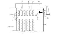
治具固定台23は、環状ワークWを吊り下げ支持するための治具10を所定の姿勢で固定的に保持する。本実施形態の治具固定台23は、図3Aおよび図3Bに示すように、治具10の一端が取り付けられる取り付け穴23aを有し、この取り付け穴23aに治具10の一端が取り付けらると、治具10が横姿勢(治具10の長手方向を水平方向に沿わせた姿勢)で保持される。治具支持台24は、所定個数の治具10を支持しており、アセンブリA(サブアセンブリA’)の組立時には、治具支持台24に支持された治具10、あるいは治具搬送装置9によって解体装置30から搬送されてくる治具10の何れかが治具固定台23に取り付けられる。
図3Bに示すように、治具固定台23には、この固定台23に治具10が横姿勢で固定的に保持されたとき、治具10に設けられたワーク支持部12の位置情報を取得(検出)するための組立用検出装置40が設置されている。組立用検出装置40は、治具固定台23に保持される治具10の側方に配置され、治具10の側面画像を撮像可能な撮像装置41と、治具10を挟んで撮像装置41のレンズ面41aと対向配置された面発光パネル(平面照明)42と、撮像装置41に電気的に接続された制御装置43とを具備する。制御装置43は、組立ロボット21(図1参照)の動作を制御するために各種情報から指令情報を演算し、動作指令を組立ロボット21に対して出力するものである。すなわち、制御装置43は、撮像装置41が撮像した治具10の側面画像のデータを取り込み、このデータに基づいて各ワーク支持部12の位置情報(鉛直方向および水平方向の位置情報)を検出すると共に、この位置情報およびワークサイズ等に基づき動作指令を組立ロボット21に対して出力する。
面発光パネル42は、発光しない平板状の部材に置き換えても構わないが、撮像装置41が撮像した治具10のシルエットを際立たせ、各ワーク支持部12の正確な位置情報を取得可能とする上では面発光パネル42を使用するのが好ましい。
ハンド支持台25は、図4に概念的に示すように、組立ロボット21のアーム部先端に装着される各種ハンド、ここでは、ワーク取付作業用ハンド51、治具搬送作業用ハンド52および容器搬送作業用ハンド53を支持する。ワーク取付作業用ハンド51は、ワーク支持台22に支持された環状ワークWを一個取得し、取得した環状ワークWを治具固定台23(図1参照)に横姿勢で保持された治具10のワーク支持部12に対して吊り下げる作業(ワーク取付作業)を実行するためのハンドであり、ここでは環状ワークWの側面(端面)を吸着可能な吸着パッド51aを備えたものが使用される。治具搬送作業用ハンド52は、組立装置20内(図1参照)で治具10(環状ワークWを吊り下げ支持しているか否かは問わない)を搬送する治具搬送作業を実行するためのハンドであり、ここでは治具10の端部を把持可能な一対のチャック爪52aを備えたものが使用される。容器搬送作業用ハンド53は、組立装置20内で容器13(治具10を支持しているか否かは問わない)を搬送する容器搬送作業を実行するためのハンドであり、ここでは容器13のフランジ部13dを把持可能な一対のチャック爪53aを備えたものが使用される。
図4に示すように、組立ロボット21のアーム部先端には、各種ハンドの装着および交換作業を自動で実行するためのハンドチェンジャーの雄部50aが取り付けられており、各ハンド51~53は、ハンドチェンジャーの雄部50aと結合する雌部50bを備えている。これにより、熱処理システム1の稼働時(組立ロボット21の作動時)には、図3Bに示す制御装置43から出力される動作指令に基づき、組立ロボット21によって実行される各種作業に応じた一のハンドが組立ロボット21のアーム部先端に自動で装着され、また、組立ロボット21によって実行される作業が切り換わる時には、アーム部先端に装着された上記一のハンドが他のハンドに自動的に交換される。
本実施形態のアセンブリ支持台26は、図1に示すように、第1支持台26Aと、熱処理炉2の入口に隣接配置された第2支持台26Bとを有する。詳細な図示は省略しているが、第2支持台26Bは、その上面で支持するアセンブリAに対して熱処理炉2内に向かう方向の搬送力を付与可能に構成されており、アセンブリAの完成後には、所定のタイミングでアセンブリAを熱処理炉2内に自動投入する。
図1に示すように、解体装置30は、熱処理炉2外に搬出されたアセンブリAを解体するためのものであり、三次元動作可能なアーム部を有する解体ロボット31と、解体ロボット31の周囲に設置されたワーク支持台32、治具固定台33、治具支持台34、ハンド支持台35およびアセンブリ支持台36と、ワーク移載用ロボット38とを備える。
アセンブリ支持台36は、熱処理炉2の出口に隣接配置され、熱処理炉2外に搬出されたアセンブリAを受け取る第1支持台36Aと、第1支持台36Aに隣接配置された第2支持台36Bとを有する。
ワーク支持台32は、治具10から取り外された環状ワークW’を一時的に支持(仮置き)する。このワーク支持台32に支持された環状ワークW’は、ワーク移載用ロボット38によってワーク搬送装置37に移載された後、ワーク搬送装置37によって図示外の後工程に搬送される。
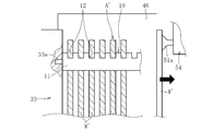
治具固定台33は、アセンブリA(サブアセンブリA’)の解体作業を実行するに際し、環状ワークW’を吊り下げ支持した治具10(サブアセンブリA’を構成する治具10)を所定の姿勢で固定的に保持する。本実施形態では、図5Aに示すように、組立装置20に設けられた治具固定台23(図3A参照)と同様の構造を有する治具固定台33が使用され、治具10を横姿勢で保持する。治具支持台34は、全ての環状ワークW’が取り外されることによって空になった治具10を支持する。
図5Bに示すように、治具固定台33には、この固定台33に環状ワークW’を吊り下げ支持した治具10が横姿勢で固定的に保持されたとき、治具10が吊り下げ支持した各環状ワークW’の位置情報(例えば、各環状ワークW’の上端部の位置情報)を取得するための解体用検出装置44が設置されている。解体用検出装置44は、組立装置20に設けられた組立用検出装置40(図3B参照)と同様に、治具固定台33に保持される治具10の側方に配置され、治具10および環状ワークW’の側面画像を撮像可能な撮像装置45と、治具10(サブアセンブリA’)を挟んで撮像装置45のレンズ面45aと対向配置された面発光パネル(平面照明)46と、撮像装置45に電気的に接続された制御装置47とを具備する。制御装置47は、解体ロボット31(図1参照)の動作を制御するために各種情報から指令情報を演算し、動作指令を出力するものである。すなわち、制御装置47は、撮像装置45が撮像した治具10および環状ワークW’の側面画像のデータを取り込み、このデータに基づいて各環状ワークW’の位置情報(鉛直方向および水平方向の位置情報)を検出すると共に、この位置情報およびワークサイズ等に基づき動作指令を解体ロボット31に対して出力する。
図4に併せて示すように、ハンド支持台35は、解体ロボット31のアーム部先端に装着される各種ハンド、ここでは、ワーク取外し作業用ハンド54、治具搬送作業用ハンド55および容器搬送作業用ハンド56を支持する。ワーク取外し作業用ハンド54は、治具固定台33に固定的に保持された治具10から環状ワークW’を一個取得し、取得した環状ワークW’をワーク支持台32に移載するワーク取外し作業を実行するために用いられるハンドであり、前述したワーク取付作業用ハンド51と同様のものが使用される。治具搬送作業用ハンド55は、解体装置30内(図1参照)で治具10を搬送する作業を実行するために用いられるハンドであり、前述した治具搬送作業用ハンド52と同様のものが使用される。容器搬送作業用ハンド56は、解体装置30内で容器13を搬送する作業を実行するために用いられるハンドであり、前述した容器搬送作業用ハンド53と同様のものが使用される。また、解体ロボット31のアーム部先端には、各ハンド54~56の装着および交換作業を自動で実行するためのハンドチェンジャーの雄部50aが取り付けられており、各ハンド54~56は、ハンドチェンジャーの雄部50aに結合される雌部50bを備えている。
以上の構成を有する熱処理システム1の連続稼働時には、アセンブリAの組立作業、アセンブリAを構成する複数の環状ワークWに対する浸炭熱処理、およびアセンブリAの解体作業が同時的に実行される。
以下、以上で説明した組立装置20の動作態様、すなわちアセンブリAの組立に際して組立ロボット21およびワーク移載ロボット28がそれぞれ実行する作業について説明する。図6を参照して組立ロボット21が順に実行する作業を簡単に説明すると、組立ロボット21は、治具搬送作業としての治具固定作業S11と、ワーク取付作業S12と、治具搬送作業としての治具移載作業S13と、容器搬送作業としての容器移載作業S14とを自動で実行する。一方、移載ロボット28はワーク移載作業を自動で実行する。以下、各作業の詳細を説明する。
[ワーク移載作業]
熱処理設備1が稼働され、図示外の前工程から搬送コンベア27によって環状ワークWが搬送されてくると、ワーク移載用ロボット28は環状ワークWを搬送コンベア27からワーク支持台22に移載する。このワーク移載作業は、前工程から環状ワークWが搬送されてくる間、継続して実行される。
熱処理設備1が稼働され、図示外の前工程から搬送コンベア27によって環状ワークWが搬送されてくると、ワーク移載用ロボット28は環状ワークWを搬送コンベア27からワーク支持台22に移載する。このワーク移載作業は、前工程から環状ワークWが搬送されてくる間、継続して実行される。
[治具固定作業S11]
ワーク支持台22に環状ワークWが移載されてくると組立ロボット21が作動し、そのアーム部先端にハンド支持台25に支持された治具搬送作業用ハンド52が装着される。治具搬送作業用ハンド52を装着した組立ロボット21は、治具支持台24に予め支持された治具10を一個取得し、取得した治具10を治具固定台23の取り付け孔23aに取り付ける治具固定作業S11を実行する。なお、熱処理設備1が連続稼働され、解体装置30に設けた解体ロボット31によって環状ワークW’が取り外された空の治具10が治具搬送装置9によって組立装置20に返送されている間、組立ロボット21に装着された治具搬送作業用ハンド52は、治具搬送装置9によって返送されてくる治具10を取得する。
ワーク支持台22に環状ワークWが移載されてくると組立ロボット21が作動し、そのアーム部先端にハンド支持台25に支持された治具搬送作業用ハンド52が装着される。治具搬送作業用ハンド52を装着した組立ロボット21は、治具支持台24に予め支持された治具10を一個取得し、取得した治具10を治具固定台23の取り付け孔23aに取り付ける治具固定作業S11を実行する。なお、熱処理設備1が連続稼働され、解体装置30に設けた解体ロボット31によって環状ワークW’が取り外された空の治具10が治具搬送装置9によって組立装置20に返送されている間、組立ロボット21に装着された治具搬送作業用ハンド52は、治具搬送装置9によって返送されてくる治具10を取得する。
[ワーク取付作業S12]
治具固定作業S11の完了後、組立ロボット21のアーム部先端に装着された治具搬送作業用ハンド52がハンド支持台25に支持されたワーク取付作業用ハンド51に自動で交換される。ハンド交換後、組立ロボット21は、ワーク支持台22に支持された環状ワークWを一個取得(吸着)し、取得した環状ワークWを治具固定台23に横姿勢で保持された治具10のワーク支持部12に対して吊り下げるワーク取付作業S12を実行する。このワーク取付作業S12は、所定回数(通常は、ワーク支持部12の個数に応じた回数)繰り返し実行される。これにより、治具10に所定個数の環状ワークWが吊り下げ支持されたサブアセンブリA’が完成する。
治具固定作業S11の完了後、組立ロボット21のアーム部先端に装着された治具搬送作業用ハンド52がハンド支持台25に支持されたワーク取付作業用ハンド51に自動で交換される。ハンド交換後、組立ロボット21は、ワーク支持台22に支持された環状ワークWを一個取得(吸着)し、取得した環状ワークWを治具固定台23に横姿勢で保持された治具10のワーク支持部12に対して吊り下げるワーク取付作業S12を実行する。このワーク取付作業S12は、所定回数(通常は、ワーク支持部12の個数に応じた回数)繰り返し実行される。これにより、治具10に所定個数の環状ワークWが吊り下げ支持されたサブアセンブリA’が完成する。
図3Bを参照して説明したように、組立装置20には組立用検出装置40が設けられており、組立ロボット21がワーク取付作業S12を実行するときには、組立用検出装置40によって取得されたワーク支持部12の位置情報に基づく動作指令が制御装置43から組立ロボット21に入力される。組立ロボット21は、入力された動作指令に基づき、そのアーム部先端に装着されたワーク取付作業用ハンド51の位置(特に鉛直方向位置)を補正しながらワーク取付作業S12を実行する。すなわち、組立ロボット21によるワーク取付作業S12の実行時には、組立用検出装置40で取得されたワーク支持部12の位置情報に基づいて、組立ロボット21に装着されたワーク取付用ハンド51の位置制御が行われる。
そのため、反り等の変形が生じた治具10が使用されている場合でも、その変形(変形量)に応じて組立ロボット21に装着されたワーク取付作業用ハンド51(およびこれに保持される環状ワークW)の位置制御を行うことができるので、ワーク取付作業S12の実行時に作業ミスが生じるのを効果的に防止することができる。これにより、サブアセンブリA’の組立作業を自動化しても特段の問題は生じず、アセンブリAの組立作業に介在する人手作業を適切に減じることができる。
なお、ワーク支持部12の位置情報は、ワーク取付作業S12の実行前に1回だけ取得(検出)するようにしても良いし、ワーク取付作業S12が実行される毎に取得するようにしても良い。治具10の変形量は、環状ワークWの支持個数によって変化する可能性があることから、ワーク取付作業S12が実行される毎にワーク支持部12の位置情報を取得するようにすれば、ワーク取付作業S12の作業ミスの発生確率を低減する上で有利となる。
[治具移載作業S13]
ワーク取付作業S12の完了後、組立ロボット21のアーム部先端に装着されたワーク取付作業用ハンド51が、ハンド支持台25に支持された治具搬送作業用ハンド52に自動で交換される。ハンド交換後、組立ロボット21は、所定個数の環状ワークWを吊り下げ支持してなる治具10(サブアセンブリA’)を治具固定台23から取り外し、取り外したサブアセンブリA’をアセンブリ支持台26の第1支持台26Aに載置された容器13に取り付ける治具移載作業S13を実行する。本実施形態の容器13は、図2に示すように、治具10(サブアセンブリA’)を二列支持可能であることから、組立ロボット21は、以上で説明した治具固定作業S11~治具移載作業S13を計2サイクル実行する。
ワーク取付作業S12の完了後、組立ロボット21のアーム部先端に装着されたワーク取付作業用ハンド51が、ハンド支持台25に支持された治具搬送作業用ハンド52に自動で交換される。ハンド交換後、組立ロボット21は、所定個数の環状ワークWを吊り下げ支持してなる治具10(サブアセンブリA’)を治具固定台23から取り外し、取り外したサブアセンブリA’をアセンブリ支持台26の第1支持台26Aに載置された容器13に取り付ける治具移載作業S13を実行する。本実施形態の容器13は、図2に示すように、治具10(サブアセンブリA’)を二列支持可能であることから、組立ロボット21は、以上で説明した治具固定作業S11~治具移載作業S13を計2サイクル実行する。
[容器移載作業S14]
治具移載作業S13の完了後(本実施形態では治具固定作業S11~治具移載作業S13が2サイクル実行された後)、組立ロボット21のアーム部先端に装着された治具搬送作業用ハンド52が、ハンド支持台25に支持された容器搬送作業用ハンド53に自動で交換される。ハンド交換後、組立ロボット21は、アセンブリ支持台26の第1支持台26Aに載置された容器13を取得し、取得した容器13を第2支持台26Bに移載する容器移載作業S14を実行する。容器13の移載後、組立ロボット21は、空の容器13を取得し、取得した容器13をアセンブリ支持台26の第1支持台26Aに載置する。なお、組立ロボット21は、図示外の容器置き場、あるいは容器搬送装置8によって解体装置30から組立装置20に向けて返送されてくる空の容器13を取得する。
治具移載作業S13の完了後(本実施形態では治具固定作業S11~治具移載作業S13が2サイクル実行された後)、組立ロボット21のアーム部先端に装着された治具搬送作業用ハンド52が、ハンド支持台25に支持された容器搬送作業用ハンド53に自動で交換される。ハンド交換後、組立ロボット21は、アセンブリ支持台26の第1支持台26Aに載置された容器13を取得し、取得した容器13を第2支持台26Bに移載する容器移載作業S14を実行する。容器13の移載後、組立ロボット21は、空の容器13を取得し、取得した容器13をアセンブリ支持台26の第1支持台26Aに載置する。なお、組立ロボット21は、図示外の容器置き場、あるいは容器搬送装置8によって解体装置30から組立装置20に向けて返送されてくる空の容器13を取得する。
サブアセンブリA’を支持した容器13を三段積みしてなるアセンブリAが熱処理炉2に投入される本実施形態では、組立ロボット21は、以上で説明した治具固定作業S11~容器移載作業S14を計3サイクル実行する。3サイクル実行すると、アセンブリ支持台26の第2支持台26Bにおいて、サブアセンブリA’を支持した容器13が三段積みされることになる。これにより、図2に示すアセンブリAが完成する。完成したアセンブリAは熱処理炉2内に投入され、アセンブリAに含まれる複数の環状ワークWのそれぞれに対して浸炭熱処理としての浸炭焼入れ焼戻しが施される。
以上で説明したように、本実施形態の熱処理システム1では、熱処理炉2に投入されるアセンブリAの組立時に実行される全ての作業が、組立ロボット21によって自動で実行される。そのため、アセンブリAの組立に際して人手作業が実質的に不要となるので、複数の環状ワークWに対して同時に浸炭熱処理を施す浸炭熱処理工程の生産性を格段に高めることが(浸炭熱処理工程を効率良くかつ低コストに実施することが)可能となる。
次に、前述した解体装置30の動作態様、すなわちアセンブリAの解体に際して解体ロボット31およびワーク移載ロボット38がそれぞれ自動で実行する作業について説明する。図7を参照して解体ロボット31が実行する作業を簡単に説明すると、解体ロボット31は、容器搬送作業としての第1の容器移載作業S21と、治具搬送作業としてのサブアセンブリ取外し作業S22と、ワーク取外し作業S23と、治具搬送作業としての治具取外し作業S24と、容器搬送作業としての第2の容器移載作業S25とを順に実行する。一方、ワーク移載ロボット38は、解体ロボット31がワーク取外し作業S23を実行することによってワーク支持台32に支持された環状ワークW’をワーク搬送装置37に移載する。以下、各作業の詳細を説明する。
[第1の容器移載作業S21]
熱処理炉2外にアセンブリAが搬出され、当該アセンブリAがアセンブリ支持台36の第1支持台36Aに載置されると、解体ロボット31が作動し、そのアーム部先端にハンド支持台35に支持された容器搬送作業用ハンド56が装着される。容器搬送作業用ハンド56を装着した解体ロボット31は、アセンブリ支持台36の第1支持台36Aに載置されたアセンブリAのうち、最上段の容器13を取得し、取得した容器13をアセンブリ支持台36の第2支持台36Bに移載する第1の容器移載作業S21を実行する。
熱処理炉2外にアセンブリAが搬出され、当該アセンブリAがアセンブリ支持台36の第1支持台36Aに載置されると、解体ロボット31が作動し、そのアーム部先端にハンド支持台35に支持された容器搬送作業用ハンド56が装着される。容器搬送作業用ハンド56を装着した解体ロボット31は、アセンブリ支持台36の第1支持台36Aに載置されたアセンブリAのうち、最上段の容器13を取得し、取得した容器13をアセンブリ支持台36の第2支持台36Bに移載する第1の容器移載作業S21を実行する。
[サブアセンブリ取外し作業S22]
第1の容器移載作業S21の完了後、解体ロボット31のアーム部先端に装着された容器搬送作業用ハンド56がハンド支持台35に支持された治具搬送作業用ハンド55に自動で交換される。ハンド交換後、解体ロボット31は、第2支持台36Bに載置された容器13が支持しているサブアセンブリA’を取得して取り外し、取り外したサブアセンブリA’の治具10を治具固定台33の取り付け穴33aに取り付けるサブアセンブリ取外し作業S22を実行する。
第1の容器移載作業S21の完了後、解体ロボット31のアーム部先端に装着された容器搬送作業用ハンド56がハンド支持台35に支持された治具搬送作業用ハンド55に自動で交換される。ハンド交換後、解体ロボット31は、第2支持台36Bに載置された容器13が支持しているサブアセンブリA’を取得して取り外し、取り外したサブアセンブリA’の治具10を治具固定台33の取り付け穴33aに取り付けるサブアセンブリ取外し作業S22を実行する。
[ワーク取外し作業S23]
サブアセンブリ取外し作業S22の完了後、解体ロボット31のアーム部先端に装着された治具搬送作業用ハンド55がハンド支持台35に支持されたワーク取外し用ハンド54に自動で交換される。ハンド交換後、解体ロボット31は、治具固定台33に横姿勢で保持されたサブアセンブリA’(治具10)から環状ワークW’を一個取得(吸着)して取り外し、取り外した環状ワークW’をワーク支持台32に移載するワーク取外し作業S23を実行する。このワーク取外し作業S23は、治具10に吊り下げ支持された環状ワークW’の個数に応じた回数繰り返し実行される。
サブアセンブリ取外し作業S22の完了後、解体ロボット31のアーム部先端に装着された治具搬送作業用ハンド55がハンド支持台35に支持されたワーク取外し用ハンド54に自動で交換される。ハンド交換後、解体ロボット31は、治具固定台33に横姿勢で保持されたサブアセンブリA’(治具10)から環状ワークW’を一個取得(吸着)して取り外し、取り外した環状ワークW’をワーク支持台32に移載するワーク取外し作業S23を実行する。このワーク取外し作業S23は、治具10に吊り下げ支持された環状ワークW’の個数に応じた回数繰り返し実行される。
図5Aおよび図5Bを参照して説明したように、解体装置30には解体用検出装置44が設けられており、解体ロボット31がワーク取外し作業S23を実行するときには、治具10に支持された環状ワークW’の位置情報(特に鉛直方向の位置情報)が解体用検出装置44によって取得(検出)され、取得された環状ワークW’の位置情報に基づく動作指令が制御装置47から解体ロボット31に入力される。解体ロボット31は、入力された動作指令に基づき、そのアーム部先端に装着されたワーク取外し作業用ハンド54の位置を補正しながらワーク取外し作業S23を実行する。すなわち、解体ロボット31によるワーク取外し作業S23の実行時には、解体用検出装置44で取得された環状ワークW’の位置情報に基づいて、解体ロボット31に装着されたワーク取外し用ハンド54の位置制御が行われる。
そのため、熱処理炉2から非出された治具10に反り等の変形が生じていても、その変形量に応じて解体ロボット31に装着されたワーク取外し作業用ハンド54(およびこれに保持される環状ワークW’)の位置制御が行われるので、ワーク取外し作業S23の実行時における作業ミスの発生を効果的に防止することができる。これにより、アセンブリA(サブアセンブリA’)の解体作業を自動化しても特段の問題は生じず、アセンブリAの解体作業に介在する人手作業を適切に減じることができる。
環状ワークW’の位置情報は、ワーク取外し作業S23の実行前に1回だけ取得するようにしても良いし、ワーク取外し作業S23が実行される毎に取得するようにしても良い。治具10の変形量は、環状ワークW’の支持個数によって変化する可能性があることから、ワーク取外し作業S23が実行される毎に環状ワークW’の位置情報を取得するようにすれば、解体ロボット21によるワーク取外し作業S23の実行時における作業ミスの発生確率を低減する上で有利となる。
[治具取外し作業S24]
ワーク取外し作業S23の完了後、解体ロボット31のアーム部先端に装着されたワーク取外し作業用ハンド54が、ハンド支持台35に支持された治具搬送作業用ハンド55に自動で交換される。ハンド交換後、解体ロボット31は、全ての環状ワークW’が取り外された治具10を治具固定台33から取り外し、取り外した治具10を治具支持台34あるいは治具搬送装置9に移載する治具取外し作業S24を実行する。熱処理システム1の連続稼働中、取り外された治具10は治具搬送装置9に移載された後、治具搬送装置9によって組立装置20に返送される。本実施形態の容器13は、図2に示すように、治具10(サブアセンブリA’)を二列支持していることから、解体ロボット31は、以上で説明したサブアセンブリ取外し作業S22~治具取外し作業S24を計2サイクル実行する。
ワーク取外し作業S23の完了後、解体ロボット31のアーム部先端に装着されたワーク取外し作業用ハンド54が、ハンド支持台35に支持された治具搬送作業用ハンド55に自動で交換される。ハンド交換後、解体ロボット31は、全ての環状ワークW’が取り外された治具10を治具固定台33から取り外し、取り外した治具10を治具支持台34あるいは治具搬送装置9に移載する治具取外し作業S24を実行する。熱処理システム1の連続稼働中、取り外された治具10は治具搬送装置9に移載された後、治具搬送装置9によって組立装置20に返送される。本実施形態の容器13は、図2に示すように、治具10(サブアセンブリA’)を二列支持していることから、解体ロボット31は、以上で説明したサブアセンブリ取外し作業S22~治具取外し作業S24を計2サイクル実行する。
[第2の容器移載作業S25]
サブアセンブリ取外し作業S22~治具取外し作業S24を2サイクル実行した後、解体ロボット31のアーム部先端に装着された治具搬送作業用ハンド55が、ハンド支持台35に支持された容器搬送作業用ハンド56に自動で交換される。ハンド交換後、解体ロボット31は、アセンブリ支持台36の第2支持台36Bに載置された容器13(サブアセンブリA’が取り外されることによって空になった容器13)を取得し、取得した空の容器13を容器搬送装置8に移載する第2の容器移載作業S25を実行する。容器搬送装置8に移載された容器13は、組立装置20に返送され、再度アセンブリAの組立に供される。
サブアセンブリ取外し作業S22~治具取外し作業S24を2サイクル実行した後、解体ロボット31のアーム部先端に装着された治具搬送作業用ハンド55が、ハンド支持台35に支持された容器搬送作業用ハンド56に自動で交換される。ハンド交換後、解体ロボット31は、アセンブリ支持台36の第2支持台36Bに載置された容器13(サブアセンブリA’が取り外されることによって空になった容器13)を取得し、取得した空の容器13を容器搬送装置8に移載する第2の容器移載作業S25を実行する。容器搬送装置8に移載された容器13は、組立装置20に返送され、再度アセンブリAの組立に供される。
アセンブリAが三段積みされたアセンブリAで構成される本実施形態では、解体ロボット31は、以上で説明した第1の容器移載作業S21~第2の容器移載作業S25を計3サイクル実行する。これにより、熱処理炉2外に搬出されたアセンブリAの解体作業が完了する。
以上で説明したように、本実施形態の熱処理システム1では、熱処理炉2外に搬出されたアセンブリAの解体時に実行される全ての作業が、解体ロボット31によって自動で実行される。そのため、アセンブリAの解体作業を実行する際の人手作業が実質的に不要となるので、浸炭熱処理工程の生産性を一層高めることができる。
また、本実施形態の熱処理システム1は、治具10および容器13のそれぞれを解体装置30から組立装置20に向けて搬送(返送)する治具搬送装置9および容器搬送装置8を備えているので、少なくとも熱処理システム1が連続稼働され、熱処理システム1による熱処理工程が連続して実行されている間(アセンブリAの組立作業、アセンブリAを構成する複数の環状ワークWに対する熱処理およびアセンブリAの解体作業が同時的に実行されている間)は、治具10および容器13を繰り返し使用することができる。これにより、少なくとも熱処理システム1が連続稼働されている間は、治具10および/または容器13を人手作業で準備・補充等する必要がなくなるため、浸炭熱処理工程の完全自動化を実現することができる。
以上のことから、本実施形態に係る熱処理システム1は、複数の環状ワークWに対して同時に施すべき浸炭熱処理を極めて効率良くかつ低コストに実施することができる、という特徴を有する。
以上、本発明の一実施形態に係る熱処理システム1について説明したが、熱処理システム1には、本発明の要旨を逸脱しない範囲で適宜の変更を施すことが可能である。
例えば、以上で説明した実施形態では、組立ロボット21によるワーク取付作業S12の実行時に、撮像装置41が撮像した治具10の画像(画像データ)に基づいて治具10に設けられたワーク支持部12の位置情報を取得するようにしたが、ワーク支持部12の位置情報は、レーザ変位センサ等の変位センサを用いて取得することも可能である。すなわち、組立装置20に設けた組立用検出装置40は、撮像装置41に替えて変位センサを備えたもので構成することも可能である。解体装置30に設けた解体用検出装置44についても同様である。
また、以上で説明した実施形態では、横姿勢で固定的に保持された治具10のワーク支持部12に対して環状ワークWを吊り下げていくワーク取付作業S12を実行すると共に、横姿勢で固定的に保持された治具10から環状ワークW’を取り外すワーク取外し作業S23を実行するようにしたが、治具10で支持された環状ワークW(W’)が脱落等せず、検出装置40,44によって上記作業S12,S23を実行する際の位置情報取得に支障がなければ、治具10は、その長手方向が水平方向に対して多少傾いた傾斜姿勢で保持するようにしても構わない。
また、以上では、環状ワークWの一例としてスラスト軸受の軌道輪を挙げたが、本発明に係る熱処理システム1は、ロット数が大きいその他の環状ワークW、例えば転がり軸受の軌道輪に浸炭熱処理を施す場合にも好ましく用いることができる。
本発明は前述した実施形態に何ら限定されるものではなく、本発明の要旨を逸脱しない範囲内において、さらに種々なる形態で実施し得る。すなわち、本発明の範囲は、請求の範囲によって示され、さらに請求の範囲に記載の均等の意味、および範囲内のすべての変更を含む。
1 熱処理システム
2 熱処理炉
4 浸炭室
5 冷却室
8 容器搬送装置
9 治具搬送装置
10 治具
12 ワーク支持部
13 容器
20 組立装置
21 組立ロボット
30 解体装置
31 解体ロボット
40 組立用検出装置
41 撮像装置
44 解体用検出装置
45 撮像装置
51 ワーク取付作業用ハンド
52 治具搬送作業用ハンド
53 容器搬送作業用ハンド
54 ワーク取外し作業用ハンド
55 治具搬送作業用ハンド
56 容器搬送作業用ハンド
A アセンブリ
A’ サブアセンブリ
S11 治具固定作業(治具搬送作業)
S12 ワーク取付作業
S13 治具移載作業(治具搬送作業)
S14 容器移載作業(容器搬送作業)
S21 第1の容器移載作業(容器搬送作業)
S22 サブアセンブリ取外し作業(治具搬送作業)
S23 ワーク取外し作業
S24 治具取外し作業(治具搬送作業)
S25 第2の容器移載作業(容器搬送作業)
2 熱処理炉
4 浸炭室
5 冷却室
8 容器搬送装置
9 治具搬送装置
10 治具
12 ワーク支持部
13 容器
20 組立装置
21 組立ロボット
30 解体装置
31 解体ロボット
40 組立用検出装置
41 撮像装置
44 解体用検出装置
45 撮像装置
51 ワーク取付作業用ハンド
52 治具搬送作業用ハンド
53 容器搬送作業用ハンド
54 ワーク取外し作業用ハンド
55 治具搬送作業用ハンド
56 容器搬送作業用ハンド
A アセンブリ
A’ サブアセンブリ
S11 治具固定作業(治具搬送作業)
S12 ワーク取付作業
S13 治具移載作業(治具搬送作業)
S14 容器移載作業(容器搬送作業)
S21 第1の容器移載作業(容器搬送作業)
S22 サブアセンブリ取外し作業(治具搬送作業)
S23 ワーク取外し作業
S24 治具取外し作業(治具搬送作業)
S25 第2の容器移載作業(容器搬送作業)
Claims (9)
- 少なくとも浸炭室および冷却室を有する熱処理炉と、該熱処理炉内に投入されるアセンブリを組み立てる組立装置とを備え、前記アセンブリが、環状ワークを相互に非接触の状態で複数個吊り下げ支持した軸状の治具と、該治具の両端を支持した容器とを含む熱処理システムであって、
前記組立装置は、所定姿勢で保持された前記治具に対して環状ワークを一個ずつ吊り下げていくワーク取付作業を繰り返し実行可能な組立ロボットと、所定姿勢で保持された前記治具が有するワーク支持部の位置情報を取得する組立用検出装置とを備え、
前記ワーク取付作業の実行時、前記組立用検出装置が取得した前記位置情報に基づいて、前記組立ロボットに装着されたワーク取付作業用ハンドの位置制御が行われることを特徴とする熱処理システム。 - 前記組立用検出装置は、撮像画像に基づいて前記位置情報を取得する請求項1に記載の熱処理システム。
- 前記組立ロボットは、前記組立装置内で前記治具を搬送する治具搬送作業および前記容器を搬送する容器搬送作業が実行可能であると共に、前記ワーク取付作業用ハンド、前記組立装置内での治具搬送作業用ハンドおよび容器搬送作業用ハンドの群から選択される一のハンドから他のハンドへの自動交換が実行可能である請求項1又は2に記載の熱処理システム。
- 前記熱処理炉外に搬出された前記アセンブリを解体する解体装置をさらに備え、
前記解体装置は、所定姿勢で保持された前記治具から環状ワークを一個ずつ取り外すワーク取外し作業を繰り返し実行可能な解体ロボットと、取外し対象の環状ワークの位置情報を取得する解体用検出装置とを備え、
前記ワーク取外し作業の実行時、前記解体用検出装置が取得した前記位置情報に基づいて、前記解体ロボットに装着されたワーク取外し作業用ハンドの位置制御が行われる請求項1~3の何れか一項に記載の熱処理システム。 - 前記解体用検出装置は、撮像画像に基づいて取外し対象の環状ワークの位置情報を取得する請求項4に記載の熱処理システム。
- 前記解体ロボットは、前記解体装置内で前記治具を搬送する治具搬送作業および前記容器を搬送する容器搬送作業が実行可能であると共に、前記ワーク取外し作業用ハンド、前記解体装置内での治具搬送作業用ハンドおよび容器搬送作業用ハンドの群から選択される一のハンドから他のハンドへの自動交換が実行可能である請求項4又は5に記載の熱処理システム。
- 前記治具および前記容器のそれぞれを、前記解体装置から前記組立装置に向けて搬送可能な治具搬送装置および容器搬送装置をさらに備える請求項4~6の何れか一項に記載の熱処理システム。
- 環状ワークがスラスト軸受の軌道輪又は転がり軸受の軌道輪である請求項1~7の何れか一項に記載の熱処理システム。
- 環状ワークを相互に非接触の状態で複数個吊り下げ支持した軸状の治具と、該治具の両端を支持した容器とを含むアセンブリを組み立てた後、該アセンブリを、少なくとも浸炭室および冷却室を有する熱処理炉に投入することにより、複数の環状ワークのそれぞれに浸炭熱処理を施す熱処理方法であって、
前記アセンブリの組み立てを、所定姿勢で保持された前記治具に対して環状ワークを一個ずつ吊り下げていくワーク取付作業を繰り返し実行可能な組立ロボットを用いて実行し、前記ワーク取付作業の実行時、所定姿勢で保持された前記治具が有するワーク支持部の位置情報に基づいて、前記組立ロボットに装着したワーク取付作業用ハンドの位置制御を行うことを特徴とする熱処理方法。
Applications Claiming Priority (2)
| Application Number | Priority Date | Filing Date | Title |
|---|---|---|---|
| JP2017-163351 | 2017-08-28 | ||
| JP2017163351A JP6890503B2 (ja) | 2017-08-28 | 2017-08-28 | 熱処理システムおよび熱処理方法 |
Publications (1)
| Publication Number | Publication Date |
|---|---|
| WO2019044768A1 true WO2019044768A1 (ja) | 2019-03-07 |
Family
ID=65525363
Family Applications (1)
| Application Number | Title | Priority Date | Filing Date |
|---|---|---|---|
| PCT/JP2018/031575 Ceased WO2019044768A1 (ja) | 2017-08-28 | 2018-08-27 | 熱処理システムおよび熱処理方法 |
Country Status (2)
| Country | Link |
|---|---|
| JP (1) | JP6890503B2 (ja) |
| WO (1) | WO2019044768A1 (ja) |
Cited By (2)
| Publication number | Priority date | Publication date | Assignee | Title |
|---|---|---|---|---|
| CN110512059A (zh) * | 2019-10-08 | 2019-11-29 | 王世民 | 一种方便固定齿轮轴淬火的工装 |
| CN117845211A (zh) * | 2024-02-19 | 2024-04-09 | 西安热工研究院有限公司 | 一种热处理装置 |
Families Citing this family (1)
| Publication number | Priority date | Publication date | Assignee | Title |
|---|---|---|---|---|
| KR102560783B1 (ko) * | 2022-12-16 | 2023-07-27 | (주)이에프씨 | 인조흑연 생산 자동화 장치 |
Citations (6)
| Publication number | Priority date | Publication date | Assignee | Title |
|---|---|---|---|---|
| JPH0913120A (ja) * | 1995-06-26 | 1997-01-14 | Fuji Heavy Ind Ltd | 熱処理用治具 |
| JPH1121631A (ja) * | 1997-07-07 | 1999-01-26 | Ntn Corp | 薄板部品の焼入れ方法 |
| JP2002544464A (ja) * | 1999-05-05 | 2002-12-24 | ソシエテ・ナシオナル・デテユード・エ・ドウ・コンストリユクシオン・ドウ・モトール・ダヴイアシオン、“エス.エヌ.ウ.セ.エム.アー.” | 熱処理用製品置きラック |
| JP2004285386A (ja) * | 2003-03-20 | 2004-10-14 | Fuji Heavy Ind Ltd | 熱処理用治具 |
| JP2006009092A (ja) * | 2004-06-25 | 2006-01-12 | Sumitomo Denko Shoketsu Gokin Kk | 焼結部品の熱処理治具及びそれを用いたリング状焼結部品の熱処理方法 |
| JP2016079428A (ja) * | 2014-10-14 | 2016-05-16 | トヨタ自動車株式会社 | 熱処理用支持具 |
-
2017
- 2017-08-28 JP JP2017163351A patent/JP6890503B2/ja not_active Expired - Fee Related
-
2018
- 2018-08-27 WO PCT/JP2018/031575 patent/WO2019044768A1/ja not_active Ceased
Patent Citations (6)
| Publication number | Priority date | Publication date | Assignee | Title |
|---|---|---|---|---|
| JPH0913120A (ja) * | 1995-06-26 | 1997-01-14 | Fuji Heavy Ind Ltd | 熱処理用治具 |
| JPH1121631A (ja) * | 1997-07-07 | 1999-01-26 | Ntn Corp | 薄板部品の焼入れ方法 |
| JP2002544464A (ja) * | 1999-05-05 | 2002-12-24 | ソシエテ・ナシオナル・デテユード・エ・ドウ・コンストリユクシオン・ドウ・モトール・ダヴイアシオン、“エス.エヌ.ウ.セ.エム.アー.” | 熱処理用製品置きラック |
| JP2004285386A (ja) * | 2003-03-20 | 2004-10-14 | Fuji Heavy Ind Ltd | 熱処理用治具 |
| JP2006009092A (ja) * | 2004-06-25 | 2006-01-12 | Sumitomo Denko Shoketsu Gokin Kk | 焼結部品の熱処理治具及びそれを用いたリング状焼結部品の熱処理方法 |
| JP2016079428A (ja) * | 2014-10-14 | 2016-05-16 | トヨタ自動車株式会社 | 熱処理用支持具 |
Cited By (3)
| Publication number | Priority date | Publication date | Assignee | Title |
|---|---|---|---|---|
| CN110512059A (zh) * | 2019-10-08 | 2019-11-29 | 王世民 | 一种方便固定齿轮轴淬火的工装 |
| CN110512059B (zh) * | 2019-10-08 | 2021-03-26 | 南通今朝机床有限公司 | 一种方便固定齿轮轴淬火的工装 |
| CN117845211A (zh) * | 2024-02-19 | 2024-04-09 | 西安热工研究院有限公司 | 一种热处理装置 |
Also Published As
| Publication number | Publication date |
|---|---|
| JP6890503B2 (ja) | 2021-06-18 |
| JP2019039053A (ja) | 2019-03-14 |
Similar Documents
| Publication | Publication Date | Title |
|---|---|---|
| JP5161335B2 (ja) | 基板の搬送装置及びこれを備えた基板の加工装置 | |
| WO2019044768A1 (ja) | 熱処理システムおよび熱処理方法 | |
| CN102122609B (zh) | 自动排序的多向流水线处理设备 | |
| WO2021174963A1 (zh) | 自动化生产线及电机转子生产线 | |
| JP6045537B2 (ja) | レンズユニット組立装置及びその方法 | |
| JP6299769B2 (ja) | ロボットシステム | |
| JP2007107941A (ja) | 検査工程の搬送装置及び検査工程の搬送方法 | |
| JP7154072B2 (ja) | 搬送装置及び搬送ロボット | |
| TW201804565A (zh) | 機器人、機器人之控制方法、教示用治具及機器人之教示方法 | |
| TWI593610B (zh) | 玻璃板保持具、玻璃板移動限制裝置及玻璃物品之製造方法 | |
| JP5917386B2 (ja) | 多関節型双腕ロボットによる生産システムおよび生産ライン | |
| JP5606546B2 (ja) | ワーク処理装置 | |
| JP6700124B2 (ja) | 搬送対象物を搬送する搬送方法 | |
| JP2005017386A (ja) | 平板状ワークの検査、修正装置 | |
| KR101337563B1 (ko) | 감지유닛을 이용하여 매니퓰레이터의 위치를 조절하는 이송장치 | |
| KR102389582B1 (ko) | 휠베어링의 허브용 유도가열 열처리 자동화장치 | |
| JP5895376B2 (ja) | ロボットセルの位置合わせ方法及び位置合わせ制御装置 | |
| CN210938297U (zh) | 供料装置和数控机床 | |
| KR20190056548A (ko) | 포토마스크 표면 이물질 세정방법 | |
| JP5799304B2 (ja) | 露光ユニット及びそれを用いた露光方法 | |
| KR101600394B1 (ko) | 반도체 부품 적재용 매거진 이송장치 | |
| CN108352350B (zh) | 搬运系统 | |
| JP4596144B2 (ja) | ウェーハ搬送方法及びウェーハ搬送装置 | |
| CN220290763U (zh) | 一站式电浆制程系统 | |
| KR102285983B1 (ko) | 볼 스터드의 고주파 열처리 자동화 방법 |
Legal Events
| Date | Code | Title | Description |
|---|---|---|---|
| 121 | Ep: the epo has been informed by wipo that ep was designated in this application |
Ref document number: 18850459 Country of ref document: EP Kind code of ref document: A1 |
|
| NENP | Non-entry into the national phase |
Ref country code: DE |
|
| 122 | Ep: pct application non-entry in european phase |
Ref document number: 18850459 Country of ref document: EP Kind code of ref document: A1 |