WO2019044461A1 - 車載用の電力制御装置及び車載用の電力制御システム - Google Patents
車載用の電力制御装置及び車載用の電力制御システム Download PDFInfo
- Publication number
- WO2019044461A1 WO2019044461A1 PCT/JP2018/030080 JP2018030080W WO2019044461A1 WO 2019044461 A1 WO2019044461 A1 WO 2019044461A1 JP 2018030080 W JP2018030080 W JP 2018030080W WO 2019044461 A1 WO2019044461 A1 WO 2019044461A1
- Authority
- WO
- WIPO (PCT)
- Prior art keywords
- power
- load
- control unit
- type
- vehicle
- Prior art date
- Legal status (The legal status is an assumption and is not a legal conclusion. Google has not performed a legal analysis and makes no representation as to the accuracy of the status listed.)
- Ceased
Links
Images




Classifications
-
- G—PHYSICS
- G05—CONTROLLING; REGULATING
- G05F—SYSTEMS FOR REGULATING ELECTRIC OR MAGNETIC VARIABLES
- G05F1/00—Automatic systems in which deviations of an electric quantity from one or more predetermined values are detected at the output of the system and fed back to a device within the system to restore the detected quantity to its predetermined value or values, i.e. retroactive systems
- G05F1/10—Regulating voltage or current
- G05F1/46—Regulating voltage or current wherein the variable actually regulated by the final control device is DC
- G05F1/56—Regulating voltage or current wherein the variable actually regulated by the final control device is DC using semiconductor devices in series with the load as final control devices
- G05F1/577—Regulating voltage or current wherein the variable actually regulated by the final control device is DC using semiconductor devices in series with the load as final control devices for plural loads
-
- B—PERFORMING OPERATIONS; TRANSPORTING
- B60—VEHICLES IN GENERAL
- B60R—VEHICLES, VEHICLE FITTINGS, OR VEHICLE PARTS, NOT OTHERWISE PROVIDED FOR
- B60R16/00—Electric or fluid circuits specially adapted for vehicles and not otherwise provided for; Arrangement of elements of electric or fluid circuits specially adapted for vehicles and not otherwise provided for
- B60R16/02—Electric or fluid circuits specially adapted for vehicles and not otherwise provided for; Arrangement of elements of electric or fluid circuits specially adapted for vehicles and not otherwise provided for electric constitutive elements
- B60R16/03—Electric or fluid circuits specially adapted for vehicles and not otherwise provided for; Arrangement of elements of electric or fluid circuits specially adapted for vehicles and not otherwise provided for electric constitutive elements for supply of electrical power to vehicle subsystems or for
-
- B—PERFORMING OPERATIONS; TRANSPORTING
- B60—VEHICLES IN GENERAL
- B60R—VEHICLES, VEHICLE FITTINGS, OR VEHICLE PARTS, NOT OTHERWISE PROVIDED FOR
- B60R16/00—Electric or fluid circuits specially adapted for vehicles and not otherwise provided for; Arrangement of elements of electric or fluid circuits specially adapted for vehicles and not otherwise provided for
- B60R16/02—Electric or fluid circuits specially adapted for vehicles and not otherwise provided for; Arrangement of elements of electric or fluid circuits specially adapted for vehicles and not otherwise provided for electric constitutive elements
- B60R16/04—Arrangement of batteries
-
- G—PHYSICS
- G05—CONTROLLING; REGULATING
- G05F—SYSTEMS FOR REGULATING ELECTRIC OR MAGNETIC VARIABLES
- G05F1/00—Automatic systems in which deviations of an electric quantity from one or more predetermined values are detected at the output of the system and fed back to a device within the system to restore the detected quantity to its predetermined value or values, i.e. retroactive systems
- G05F1/10—Regulating voltage or current
- G05F1/46—Regulating voltage or current wherein the variable actually regulated by the final control device is DC
- G05F1/56—Regulating voltage or current wherein the variable actually regulated by the final control device is DC using semiconductor devices in series with the load as final control devices
-
- H—ELECTRICITY
- H01—ELECTRIC ELEMENTS
- H01M—PROCESSES OR MEANS, e.g. BATTERIES, FOR THE DIRECT CONVERSION OF CHEMICAL ENERGY INTO ELECTRICAL ENERGY
- H01M10/00—Secondary cells; Manufacture thereof
- H01M10/42—Methods or arrangements for servicing or maintenance of secondary cells or secondary half-cells
- H01M10/44—Methods for charging or discharging
-
- H—ELECTRICITY
- H01—ELECTRIC ELEMENTS
- H01M—PROCESSES OR MEANS, e.g. BATTERIES, FOR THE DIRECT CONVERSION OF CHEMICAL ENERGY INTO ELECTRICAL ENERGY
- H01M10/00—Secondary cells; Manufacture thereof
- H01M10/42—Methods or arrangements for servicing or maintenance of secondary cells or secondary half-cells
- H01M10/48—Accumulators combined with arrangements for measuring, testing or indicating the condition of cells, e.g. the level or density of the electrolyte
-
- H—ELECTRICITY
- H02—GENERATION; CONVERSION OR DISTRIBUTION OF ELECTRIC POWER
- H02J—ELECTRIC POWER NETWORKS; CIRCUIT ARRANGEMENTS OR SYSTEMS FOR SUPPLYING OR DISTRIBUTING ELECTRIC POWER; SYSTEMS FOR STORING ELECTRIC ENERGY
- H02J1/00—Circuit arrangements for DC mains or DC distribution networks
- H02J1/10—Parallel operation of DC sources
- H02J1/102—Parallel operation of DC sources being switching converters
-
- H—ELECTRICITY
- H02—GENERATION; CONVERSION OR DISTRIBUTION OF ELECTRIC POWER
- H02J—ELECTRIC POWER NETWORKS; CIRCUIT ARRANGEMENTS OR SYSTEMS FOR SUPPLYING OR DISTRIBUTING ELECTRIC POWER; SYSTEMS FOR STORING ELECTRIC ENERGY
- H02J1/00—Circuit arrangements for DC mains or DC distribution networks
- H02J1/14—Balancing load and power generation in DC networks
-
- H—ELECTRICITY
- H02—GENERATION; CONVERSION OR DISTRIBUTION OF ELECTRIC POWER
- H02J—ELECTRIC POWER NETWORKS; CIRCUIT ARRANGEMENTS OR SYSTEMS FOR SUPPLYING OR DISTRIBUTING ELECTRIC POWER; SYSTEMS FOR STORING ELECTRIC ENERGY
- H02J9/00—Circuit arrangements for emergency or stand-by power supply, e.g. for emergency lighting
- H02J9/002—Circuit arrangements for emergency or stand-by power supply, e.g. for emergency lighting in which a reserve is maintained in an energy source by disconnecting non-critical loads, e.g. maintaining a reserve of charge in a vehicle battery for starting an engine
-
- H—ELECTRICITY
- H02—GENERATION; CONVERSION OR DISTRIBUTION OF ELECTRIC POWER
- H02M—APPARATUS FOR CONVERSION BETWEEN AC AND AC, BETWEEN AC AND DC, OR BETWEEN DC AND DC, AND FOR USE WITH MAINS OR SIMILAR POWER SUPPLY SYSTEMS; CONVERSION OF DC OR AC INPUT POWER INTO SURGE OUTPUT POWER; CONTROL OR REGULATION THEREOF
- H02M3/00—Conversion of DC power input into DC power output
- H02M3/02—Conversion of DC power input into DC power output without intermediate conversion into AC
- H02M3/04—Conversion of DC power input into DC power output without intermediate conversion into AC by static converters
- H02M3/10—Conversion of DC power input into DC power output without intermediate conversion into AC by static converters using discharge tubes with control electrode or semiconductor devices with control electrode
- H02M3/145—Conversion of DC power input into DC power output without intermediate conversion into AC by static converters using discharge tubes with control electrode or semiconductor devices with control electrode using devices of a triode or transistor type requiring continuous application of a control signal
- H02M3/155—Conversion of DC power input into DC power output without intermediate conversion into AC by static converters using discharge tubes with control electrode or semiconductor devices with control electrode using devices of a triode or transistor type requiring continuous application of a control signal using semiconductor devices only
- H02M3/156—Conversion of DC power input into DC power output without intermediate conversion into AC by static converters using discharge tubes with control electrode or semiconductor devices with control electrode using devices of a triode or transistor type requiring continuous application of a control signal using semiconductor devices only with automatic control of output voltage or current, e.g. switching regulators
- H02M3/157—Conversion of DC power input into DC power output without intermediate conversion into AC by static converters using discharge tubes with control electrode or semiconductor devices with control electrode using devices of a triode or transistor type requiring continuous application of a control signal using semiconductor devices only with automatic control of output voltage or current, e.g. switching regulators with digital control
-
- H—ELECTRICITY
- H02—GENERATION; CONVERSION OR DISTRIBUTION OF ELECTRIC POWER
- H02J—ELECTRIC POWER NETWORKS; CIRCUIT ARRANGEMENTS OR SYSTEMS FOR SUPPLYING OR DISTRIBUTING ELECTRIC POWER; SYSTEMS FOR STORING ELECTRIC ENERGY
- H02J1/00—Circuit arrangements for DC mains or DC distribution networks
- H02J1/06—Two-wire DC power distribution systems
-
- H—ELECTRICITY
- H02—GENERATION; CONVERSION OR DISTRIBUTION OF ELECTRIC POWER
- H02J—ELECTRIC POWER NETWORKS; CIRCUIT ARRANGEMENTS OR SYSTEMS FOR SUPPLYING OR DISTRIBUTING ELECTRIC POWER; SYSTEMS FOR STORING ELECTRIC ENERGY
- H02J2105/00—Networks for supplying or distributing electric power characterised by their spatial reach or by the load
- H02J2105/30—Networks for supplying or distributing electric power characterised by their spatial reach or by the load the load networks being external to vehicles, i.e. exchanging power with vehicles
-
- H—ELECTRICITY
- H02—GENERATION; CONVERSION OR DISTRIBUTION OF ELECTRIC POWER
- H02J—ELECTRIC POWER NETWORKS; CIRCUIT ARRANGEMENTS OR SYSTEMS FOR SUPPLYING OR DISTRIBUTING ELECTRIC POWER; SYSTEMS FOR STORING ELECTRIC ENERGY
- H02J2105/00—Networks for supplying or distributing electric power characterised by their spatial reach or by the load
- H02J2105/30—Networks for supplying or distributing electric power characterised by their spatial reach or by the load the load networks being external to vehicles, i.e. exchanging power with vehicles
- H02J2105/33—Networks for supplying or distributing electric power characterised by their spatial reach or by the load the load networks being external to vehicles, i.e. exchanging power with vehicles exchanging power with road vehicles
-
- H—ELECTRICITY
- H02—GENERATION; CONVERSION OR DISTRIBUTION OF ELECTRIC POWER
- H02J—ELECTRIC POWER NETWORKS; CIRCUIT ARRANGEMENTS OR SYSTEMS FOR SUPPLYING OR DISTRIBUTING ELECTRIC POWER; SYSTEMS FOR STORING ELECTRIC ENERGY
- H02J2105/00—Networks for supplying or distributing electric power characterised by their spatial reach or by the load
- H02J2105/50—Networks for supplying or distributing electric power characterised by their spatial reach or by the load for selectively controlling the operation of the loads
- H02J2105/52—Networks for supplying or distributing electric power characterised by their spatial reach or by the load for selectively controlling the operation of the loads for limitation of the power consumption in the networks or in one section of the networks, e.g. load shedding or peak shaving
-
- H—ELECTRICITY
- H02—GENERATION; CONVERSION OR DISTRIBUTION OF ELECTRIC POWER
- H02J—ELECTRIC POWER NETWORKS; CIRCUIT ARRANGEMENTS OR SYSTEMS FOR SUPPLYING OR DISTRIBUTING ELECTRIC POWER; SYSTEMS FOR STORING ELECTRIC ENERGY
- H02J2105/00—Networks for supplying or distributing electric power characterised by their spatial reach or by the load
- H02J2105/50—Networks for supplying or distributing electric power characterised by their spatial reach or by the load for selectively controlling the operation of the loads
- H02J2105/52—Networks for supplying or distributing electric power characterised by their spatial reach or by the load for selectively controlling the operation of the loads for limitation of the power consumption in the networks or in one section of the networks, e.g. load shedding or peak shaving
- H02J2105/53—Networks for supplying or distributing electric power characterised by their spatial reach or by the load for selectively controlling the operation of the loads for limitation of the power consumption in the networks or in one section of the networks, e.g. load shedding or peak shaving for partial power limitation, e.g. entering degraded or current limitation modes
-
- H—ELECTRICITY
- H02—GENERATION; CONVERSION OR DISTRIBUTION OF ELECTRIC POWER
- H02J—ELECTRIC POWER NETWORKS; CIRCUIT ARRANGEMENTS OR SYSTEMS FOR SUPPLYING OR DISTRIBUTING ELECTRIC POWER; SYSTEMS FOR STORING ELECTRIC ENERGY
- H02J7/00—Circuit arrangements for charging or discharging batteries or for supplying loads from batteries
- H02J7/34—Parallel operation in networks using both storage and other DC sources, e.g. providing buffering
-
- Y—GENERAL TAGGING OF NEW TECHNOLOGICAL DEVELOPMENTS; GENERAL TAGGING OF CROSS-SECTIONAL TECHNOLOGIES SPANNING OVER SEVERAL SECTIONS OF THE IPC; TECHNICAL SUBJECTS COVERED BY FORMER USPC CROSS-REFERENCE ART COLLECTIONS [XRACs] AND DIGESTS
- Y02—TECHNOLOGIES OR APPLICATIONS FOR MITIGATION OR ADAPTATION AGAINST CLIMATE CHANGE
- Y02E—REDUCTION OF GREENHOUSE GAS [GHG] EMISSIONS, RELATED TO ENERGY GENERATION, TRANSMISSION OR DISTRIBUTION
- Y02E60/00—Enabling technologies; Technologies with a potential or indirect contribution to GHG emissions mitigation
- Y02E60/10—Energy storage using batteries
-
- Y—GENERAL TAGGING OF NEW TECHNOLOGICAL DEVELOPMENTS; GENERAL TAGGING OF CROSS-SECTIONAL TECHNOLOGIES SPANNING OVER SEVERAL SECTIONS OF THE IPC; TECHNICAL SUBJECTS COVERED BY FORMER USPC CROSS-REFERENCE ART COLLECTIONS [XRACs] AND DIGESTS
- Y02—TECHNOLOGIES OR APPLICATIONS FOR MITIGATION OR ADAPTATION AGAINST CLIMATE CHANGE
- Y02T—CLIMATE CHANGE MITIGATION TECHNOLOGIES RELATED TO TRANSPORTATION
- Y02T10/00—Road transport of goods or passengers
- Y02T10/80—Technologies aiming to reduce greenhouse gasses emissions common to all road transportation technologies
- Y02T10/92—Energy efficient charging or discharging systems for batteries, ultracapacitors, supercapacitors or double-layer capacitors specially adapted for vehicles
Definitions
- the present invention relates to a vehicle-mounted power control apparatus and a vehicle-mounted power control system.
- Patent Document 1 discloses a power supply system that has a problem of suppressing energy consumption of an electric load.
- the power supply system disclosed in Patent Document 1 includes power supply voltage detection means for detecting a voltage value of a power supply line to which a power supply power supply is connected, and PWM control capable of being connected to an electrical load to which power is supplied.
- the semiconductor switch includes: a semiconductor switch; and a control unit that performs PWM control on a switch element connected to the load to control an execution power supplied to the load.
- this power supply system sets the duty ratio lower than 1 and performs PWM control of the semiconductor switch connected to the electric load to supply the power supplied to the load. Acts to suppress.
- the present invention has been made to solve at least one of the above-described problems, and provides a configuration in which the suppression method can be made different for each type of load when the power consumption of the load is to be suppressed. It is the purpose.
- the on-vehicle power control device is A vehicle-mounted power control device for use in a vehicle-mounted power control system for controlling power supply from a first conductive path electrically connected to a vehicle-mounted power supply unit to a plurality of loads, comprising: A plurality of second conductive paths which are conductive paths branched from the first conductive path; A plurality of switch parts respectively provided in the plurality of second conductive paths; A second load control unit configured to control the plurality of switch units based on a power suppression instruction from a first load control unit provided outside the power control apparatus; Have Each of the second conductive paths is configured as a power supply path to a corresponding load corresponding to each of the second conductive paths, Each of the switch units is configured to switch each of the second conductive paths between the energized state and the non-energized state.
- the second load control unit predetermines the type of each of the switch units, and when the power suppression instruction specifying the control method for each type is received from the first load control unit,
- the plurality of switch units
- the on-vehicle power control system is An in-vehicle power control system for controlling power supply from a first conductive path electrically connected to an in-vehicle power supply unit to a plurality of loads, comprising: A first load control unit that transmits a power suppression instruction when a predetermined condition is satisfied; According to the power suppression instruction from the first load control unit, a plurality of second conductive paths which are conductive paths branched from the first conductive path, a plurality of switch parts respectively provided on the plurality of second conductive paths, and And a second load control unit that controls the plurality of switch units based on the power control device.
- Each of the second conductive paths is configured as a power supply path to a corresponding load corresponding to each of the second conductive paths
- Each of the switch units is configured to switch each of the second conductive paths between the energized state and the non-energized state.
- the second load control unit predetermines the type of each of the switch units, and when the power suppression instruction specifying the control method for each type is received from the first load control unit, The plurality of switch units are controlled for each type based on a control method.
- the power control device includes a plurality of second conductive paths, a plurality of switch units provided in each of the plurality of second conductive paths, and a second load control unit configured to control the plurality of switch units. Then, the second load control unit controls the plurality of switch units for each type based on the control method for each type when the power suppression instruction specifying the control method for each type is received from the first load control unit. . With such a configuration, when the power consumption of the load is to be suppressed, the suppression method can be made different for each type of load.
- the power control apparatus can be configured separately from the first load control unit that transmits the power control instruction, and the second load control unit that controls the plurality of switch units can control the plurality of switch units for each type.
- the design of the power control system is changed to add a new load and a power supply path (second conductive path) to the new load, the control on the first load control unit side is complicated. It is easy to cope with the simple design change which makes the 2nd load control part side the main change object in the form which was suppressed.
- FIG. 1 is a block diagram schematically illustrating a vehicle-mounted system including a vehicle-mounted power supply system according to a first embodiment. It is an explanatory view explaining an example which classified a plurality of loads into every classification. It is a flowchart which illustrates the flow of the power control performed by the 1st load control part. It is an explanatory view explaining an example of a power control instruction which specified a duty for every classification. It is an explanatory view explaining a design change which adds a load newly.
- FIG. 7 is a block diagram schematically illustrating a power control system according to another embodiment. It is an explanatory view showing another example of a power control instruction.
- the second load control unit classifies the plurality of switch units based on the duty specified for each type by the power suppression instruction, when the power suppression instruction specifying the duty for each type is received from the first load control unit It may operate so as to perform PWM control every time.
- PWM control of each switch section can be performed for each type based on the duty specified for each type, so more detailed power control can be performed. It can be done for each type.
- the first load control unit controls the second load control unit to specify a control method for each type when the in-vehicle power supply unit is at least one of a predetermined charge reduction state or a predetermined deterioration state. It may be operative to send an indication.
- load power can be suppressed by a method in which the suppression method can be made different for each type of load.
- a generator may be electrically connected to the first conductive path.
- the first load control unit may operate to transmit a power suppression instruction specifying a control method for each type to the second load control unit when the generator is in a predetermined output reduction state. .
- the total power consumption of the plurality of loads can be suppressed to make it difficult for the power trouble to occur.
- the load power can be suppressed in a different manner.
- the first load control unit operates to transmit a power suppression instruction specifying a control method for each type to the second load control unit when the power consumption of a plurality of loads is in a predetermined excess state.
- the total power consumption of the plurality of loads can be suppressed to make it difficult to cause a power trouble, and moreover, it is suppressed for each type of load Load power can be reduced in a manner that allows different methods.
- An on-vehicle system 100 shown in FIG. 1 includes a battery 101, a generator 102, a first conductive path 103, a power control system 1, and the like, and is configured as a system for supplying power to a plurality of loads.
- the power control system 1 corresponds to an example of a vehicle-mounted power control system, and power from the first conductive path 103 electrically connected to the battery 101 to the plurality of loads 111, 112, 113, 114, 115, 116. Operate to control the supply.
- the battery 101 corresponds to an example of a vehicle-mounted power supply unit, and functions as a main power supply for supplying power to various objects.
- the battery 101 is configured, for example, as a well-known power storage unit for a vehicle such as a lead battery, a terminal on the high potential side is electrically connected to the first conductive path 103, and a predetermined output voltage with respect to the first conductive path 103 Apply.
- fuses and ignition switches are omitted.
- the generator 102 is configured as a known on-vehicle generator such as an alternator, and is configured to perform a power generation operation during operation of the engine and to output a predetermined voltage (generated voltage).
- the operation and output voltage (generated voltage) of the generator 102 are controlled by an electronic control unit (not shown).
- the plurality of loads 111, 112, 113, 114, 115, 116 are configured as known in-vehicle loads, and each load is a steering system, a brake system, an air conditioner, a power window, an audio, a navigation system, It corresponds to any of known vehicle load such as a seat heater.
- the power control system 1 mainly includes a first load control unit 3 and a power control device 10.
- the first load control unit 3 and the power control apparatus 10 may be configured as separate units, or may be configured as an integral unit. In the following description, an example in which the first load control unit 3 and the power control apparatus 10 are configured as separate units will be described.
- the first load control unit 3 is, for example, a device that is configured as an on-vehicle electronic control device and controls power supplied to the load.
- the first load control unit 3 is, for example, configured separately from the power control apparatus 10, configured to be able to transmit information to the power control apparatus 10 via one or more wiring units (not shown), and from the power control apparatus 10 It is configured to be able to receive information.
- the first load control unit 3 includes at least one control circuit such as a microcomputer, and functions to transmit a power suppression instruction when a predetermined condition is satisfied. The operation of the first load control unit 3 will be described later.
- the power control device 10 corresponds to an example of a vehicle-mounted power control device, and operates to control power supply to a plurality of loads based on an instruction from the first load control unit 3.
- the power control device 10 includes a second load control unit 12, a plurality of second conductive paths 31, 32, 33, 34, 35, 36 which are conductive paths branched from the first conductive path 103, and a plurality of second conductive paths.
- a second load control unit 12 that controls the units 21, 22, 23, 24, 25, 26.
- Each of the plurality of second conductive paths 31, 32, 33, 34, 35, and 36 is electrically connected to the first conductive path 103 and branched from the first conductive path 103. It is configured as a power supply path to the corresponding corresponding load.
- the second conductive path 31 is configured as a power supply path to the load 111
- the second conductive path 32 is configured as a power supply path to the load 112
- the second conductive path 33 is configured to the load 113.
- the second conductive path 34 is configured as a power supply path to the load 114
- the second conductive path 35 is configured as a power supply path to the load 115
- the second conductive path 36 is configured to the load 116. Configured as a power supply path of
- FIG. 1 shows an example in which one corresponding load is provided corresponding to each of the second conductive paths 31, 32, 33, 34, 35, 36, one or more corresponding loads are provided. It may be done.
- Each of the plurality of switch portions 21, 22, 23, 24, 25, 26 switches the configuration of each of the plurality of second conductive paths 31, 32, 33, 34, 35, 36 between the energized state and the non-energized state. It is eggplant.
- the plurality of switch units 21, 22, 23, 24, 25, 26 are all individually controlled by the second load control unit 12, and a second corresponding to the case where the power supply instruction is received from the second load control unit 12.
- the conductive path is brought into the energized state, and the second conductive path corresponding to the case where the non-conduction instruction is received is brought into the non-energized state.
- Each of the plurality of switch units 21, 22, 23, 24, 25, 26 may be configured as a semiconductor switch such as a field effect transistor (FET), and configured as a DCDC converter including such a semiconductor switch. It may be In the following description, an example in which each of the plurality of switch units 21, 22, 23, 24, 25, 26 is configured as a semiconductor switch will be described.
- FET field effect transistor
- FIG. 1 when the switch unit 21 is in the on state, the second conductive path 31 is in the conductive state, and power is supplied to the corresponding load (load 111) corresponding to the second conductive path 31.
- the second conductive path 31 When in the off state, the second conductive path 31 is de-energized (energized state) and the power supply to the corresponding load (load 111) corresponding to the second conductive path 31 is cut off.
- the switch portion 22 when the switch portion 22 is in the on state, the second conductive path 32 is in the conductive state, power is supplied to the corresponding load (load 112) corresponding to the second conductive path 32, and the switch portion 22 is in the off state. At this time, the second conductive path 32 is de-energized (energized state), and the power supply to the corresponding load (load 112) corresponding to the second conductive path 32 is cut off.
- the other switch units 23, 24, 25, 26 operate similarly to the switch units 21, 22.
- the "corresponding load corresponding to each second conductive path" is a load that can receive power supply via each second conductive path, and the number of loads may be one or more. It is also good.
- the corresponding load corresponding to the second conductive path 31 is a load that can receive power supply via the second conductive path 31 and only one load 111 is illustrated in FIG.
- the load of may be provided to be able to receive power supply via the second conductive path 31.
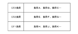
- the second load control unit 12 is configured as, for example, a control circuit including a microcomputer and the like, and includes a control unit such as a CPU and a storage unit such as a ROM and a RAM. As shown in FIG. 2, the second load control unit 12 divides the types of each of the plurality of loads into three levels and determines them in advance. For example, in the example of FIG. 1, the second load control unit 12 determines the loads 111 and 112 as loads of the first type (level 1), and defines the loads 113 and 114 as loads of the second type (level 2). The loads 115 and 116 are defined as loads of the third type (level 3).
- the load of the third type (level 3) is a load positioned as a load of high importance with the highest importance, and a load for which operation maintenance is essential during vehicle travel ( For example, a load such as a steering system or a brake system that can not properly travel or stop the vehicle when the operation is stopped is regarded as the load of the third type (level 3).
- the load of the second type is a load whose importance is lower than the load of the third type (level 3) and which is positioned as a load of higher importance than the load of the first type (level 1).
- a load eg, air conditioner, power window, audio system, etc.
- the user is likely to feel uncomfortable if the operation is stopped while the vehicle is running. It is considered as a load of 2 types (level 2).
- the load of the first type is a load that is positioned as a load of small importance whose importance is lower than the load of the second type (level 2), and the operation is stopped or suppressed while the vehicle is traveling
- a load that does not cause much trouble is regarded as the load of the third type (level 3).
- the second load control unit 12 defines the switch units 21 and 22 corresponding to the loads 111 and 112 of the first type (level 1) as the switch units of the first type (level 1), and the second type (level)
- the switch units 23 and 24 corresponding to the loads 113 and 114 in 2) are defined as the switch units of the second type (level 2), and the switch units 25 corresponding to the loads 115 and 116 of the third type (level 3) , 26 are defined as switch units of the third type (level 3).
- Information that defines the type of each switch (information specifying which switch corresponds to which type) can be stored in advance in a storage unit such as a ROM, for example.
- the first load control unit 3 performs the power control process shown in FIG. 3 when the predetermined start condition is satisfied (for example, when the start switch (ignition switch etc. of the vehicle is switched from the off state to the on state)
- the power control process of FIG. 3 is repeated until a predetermined termination condition is satisfied (for example, until a start switch (ignition switch or the like) of the vehicle is switched from the off state to the on state).
- the first load control unit 3 first grasps the power generation state of the generator 102, the state of the battery 101 (generator state such as SOC and SOH), load operation state, and the like. (Step S1).
- the first load control unit 3 determines the power generation state by determining whether the output voltage (generated voltage) of the generator 102 is equal to or higher than a predetermined threshold (voltage determination threshold).
- the first load control unit 3 detects the state of charge (SOC) of the battery 101 by a known method to grasp the state of the generator.
- the first load control unit 3 also detects the state of the generator by detecting SOH (State Of Health) of the battery 101 by a known method.
- the first load control unit 3 detects the total power consumption of the entire vehicle (total power consumption of a plurality of loads supplied with power from the first conductive path 103) by a known method, or acquires it from an external device, The load operating state is grasped by determining whether the total power consumption of the plurality of loads receiving the power supply from 103 is equal to or less than a predetermined threshold (load operating state determination threshold).
- a predetermined threshold load operating state determination threshold.
- the first load control unit 3 determines whether the power suppression condition is satisfied (step S2). Specifically, when it is determined that the output voltage (generated voltage) of the generator 102 acquired in step S1 is less than a predetermined threshold (voltage determination threshold), the SOC of the battery 101 acquired in step S1 is previously determined.
- step S1 If it is determined that the SOH of the battery 101 acquired in step S1 is less than the predetermined SOH threshold in step S1, the total power consumption of the plurality of loads acquired in step S1 (second 1) When it is determined that the total power consumption of a plurality of loads supplied with power from the conductive path 103 exceeds a predetermined load operating state determination threshold value, and the power suppression condition is satisfied when at least one of the conditions applies In this case, the power control instruction is transmitted to the second load control unit 12 (step S4). On the other hand, when it is determined that the power suppression condition is not satisfied in step S2, the first load control unit 3 transmits a predetermined normal operation instruction to the second load control unit 12 (step S3).
- the case where the SOC of the battery 101 is less than a predetermined SOC threshold value corresponds to an example of the predetermined charge amount reduction state.
- the case where the SOH of the battery 101 is less than a predetermined SOH threshold corresponds to an example of the predetermined deterioration state.
- the case where the output voltage (generated voltage) of the generator 102 is less than a predetermined threshold (voltage determination threshold) corresponds to an example of the predetermined output reduction state.
- the case where the total power consumption of the plurality of loads receiving the power supply from the first conductive path 103 exceeds the load operating state determination threshold corresponds to an example of the predetermined excess state.
- the generator 102 When the first load control unit 3 determines that the battery 101 (vehicle power supply unit) is at least one of the predetermined charge reduction state or the predetermined deterioration state, the generator 102 is in the predetermined output reduction state. In the case where the power consumption of a plurality of loads is in a predetermined excess state, an electric power suppression instruction specifying a control method for each type is transmitted to the second load control unit 12 when corresponding to at least one of them. Works to do.
- the second load control unit 12 When the second load control unit 12 receives the normal operation instruction from the first load control unit 3, the second load control unit 12 continues the plurality of switch units 21, 22, 23, 24, 25, 26 in the on state. That is, all of the switch portions 21, 22, 23, 24, 25, 26 are turned on with 100% duty.
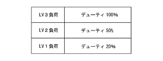
- the first load control unit 3 transmits a power suppression instruction to the second load control unit 12 when it is determined that the power suppression condition is satisfied, but the power suppression instruction designates the control method for each type. Send as instruction information. Specifically, when executing the processing of step S4, the first load control unit 3 transmits, to the second load control unit 12, a power suppression instruction specifying a duty for each type as shown in FIG. In the example of FIG. 4, a duty of 100% is designated for the load of the third type (level 3), a duty of 50% for the load of the second type (level 2), and the second type It is a power suppression instruction that specifies a 20% duty with respect to the load of level 2).
- the second load control unit 12 receives from the first load control unit 3 a power suppression instruction specifying a control method for each type, the plurality of switch units for each type is determined based on the control method for each type. Control. As described above, the second load control unit 12 causes the types of the switch units 21, 22, 23, 24, 25, 26 to correspond to the types of the loads 111, 112, 113, 114, 115, 116, respectively.
- the switch units 21, 22, 23, 24, 25, 26 are determined in advance. Is operated to perform PWM control for each type based on the duty for each type. For example, when the power suppression instruction as shown in FIG.
- the second load control unit 12 switches the switch unit 25 of the third type (level 3) corresponding to the loads 115 and 116 of the third type (level 3), 26 is driven at 100% duty (that is, the switch sections 25 and 26 are kept on), and the second type (level 2) switch section 23 corresponding to the second type (level 2) loads 113 and 114,
- a PWM signal of 50% duty is given to each of the 24 to perform PWM control with 50% duty
- the switch unit 21 of the first type (level 1) corresponding to the loads 111 and 112 of the first type (level 1)
- a PWM signal of 20% duty is given to each of 22 to perform PWM control with 20% duty.
- the power control device 10 includes a plurality of switch units provided on the plurality of second conductive paths 31, 32, 33, 34, 35, 36 and the plurality of second conductive paths 31, 32, 33, 34, 35, 36, respectively. 21, 22, 23, 24, 25, 26 and a second load control unit 12 that controls the plurality of switch units 21, 22, 23, 24, 25, 26. Then, when the second load control unit 12 receives from the first load control unit 3 the power suppression instruction specifying the control method for each type, the plurality of switch units 21, 22,, based on the control method for each type, Control 23, 24, 25 and 26 for each type. With such a configuration, when the power consumption of the load is to be suppressed, the suppression method can be made different for each type of load.
- the power control apparatus 10 is configured separately from the first load control unit 3 in which the second load control unit 12 controlling the plurality of switch units 21, 22, 23, 24, 25, 26 transmits the power control instruction.
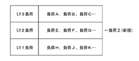
- the plurality of switch units 21, 22, 23, 24, 25, 26 can be controlled for each type, so for example, as shown in FIG. 5, a new load (load in the example of FIG. 5) Z) and the design change of the power control system so as to add the power supply path (second conductive path) to the load, in a form in which the control of the first load control unit is not complicated and It is easy to cope with a simple design change in which the second load control unit side is a main change target.
- a new load load in the example of FIG. 5
- the design change of the power control system so as to add the power supply path (second conductive path) to the load, in a form in which the control of the first load control unit is not complicated and It is easy to cope with a simple design change in which the second load control unit side is a main change target.
- the load Z is added as a load of the second type (level 2) and the corresponding switch part is a switch part of the second type (level 2).
- the load Z can be controlled as a load of the second type (level 2).
- the second load control unit 12 When the second load control unit 12 receives from the first load control unit 3 a power suppression instruction specifying a duty for each type, the second load control unit 12 switches the plurality of switch units 21, 22, 23, 24, 25, 26 It operates so as to perform PWM control for each type based on the duty of. In this way, when the power consumption of the load is to be suppressed, the PWM control of each of the plurality of switch units 21, 22, 23, 24, 25, 25 can be performed with the duty for each type. Fine power control can be performed for each type.
- the first load control unit 3 controls the second load control unit 12 for each type when the in-vehicle power supply unit (battery 101) is at least one of a predetermined charge reduction state or a predetermined deterioration state.
- the method operates to transmit a power throttling indication that specifies a method. In this way, the total power consumption of the plurality of loads can be reduced even when the charge amount of the in-vehicle power supply unit (battery 101) decreases or when the in-vehicle power supply unit (battery 101) is deteriorated. It is possible to suppress the occurrence of power troubles, and to suppress load power by a method capable of making the suppression method different for each type of load.
- the first load control unit 3 operates to transmit a power suppression instruction specifying a control method for each type to the second load control unit 12 when the generator 102 is in a predetermined output reduction state. .
- a power suppression instruction specifying a control method for each type to the second load control unit 12 when the generator 102 is in a predetermined output reduction state.
- the suppression method for each type of load The load power can be suppressed in a manner that can be made different.
- the first load control unit 3 transmits a power suppression instruction specifying a control method for each type to the second load control unit 12 when the power consumption of a plurality of loads is in a predetermined excess state. Operate. In this way, when the power consumption of a plurality of loads is in an excessive state, the total power consumption of the plurality of loads can be suppressed to make it difficult to cause a power trouble, and moreover, it is suppressed for each type of load Load power can be reduced in a manner that allows different methods.
- the first embodiment shows an example in which a plurality of switch parts are configured as semiconductor switches, but any switch part or all switch parts may apply a voltage conversion circuit including semiconductor switches (for example, to the first conductive path 103) It may be configured as a DCDC converter that boosts or steps down the voltage to apply an output voltage to the load side.
- the power suppression instruction is transmitted from the first load control unit 3 to one second load control unit 12 , but as in the on-vehicle system 200 shown in FIG.
- the configuration may be such that the power suppression instruction is transmitted to the units 212A and 212B.
- the first power control unit 210A has the same configuration as the power control apparatus 10 of the first embodiment, and the second power control unit 210B having the same configuration as the first power control unit 210A is further provided. There is.
- a power control apparatus 210 is configured by the first power control unit 210A and the second power control unit 210B.
- the sixth has the same configuration as the on-vehicle system 100 of the first embodiment except for the power control device 210.
- the power control system 201 has the same configuration as the power control system 1 of the first embodiment except for the power control apparatus 210.
- the parts having the same configuration as the in-vehicle system 100 of FIG.
- the first power control unit 210A in the first power control unit 210A, the plurality of second conductive paths 31, 32, 33, 34, 35, and 36 are electrically connected to the first conductive path 103 via the conductive path 211.
- the second load control unit 212A has the same configuration as the second load control unit 12 of the first embodiment and operates in the same manner.
- the second power control unit 210B has the same configuration as the first power control unit 210A and operates in the same manner.
- each of the second conductive paths 231, 232, 233, 234, 235, 236 is electrically connected to the first conductive path 103 via the conductive path 212, and each corresponding It is configured as a power supply path to the loads (loads 117, 118, 119, 120, 121, 122).
- Each of the switch units 221, 222, 223, 223, 225, 226 switches each of the second conductive paths 231, 232, 233, 234, 235, 236 between the energized state and the non-energized state.
- the second load control unit 212B predetermines the type of each of the switch units 221, 222, 223, 223, 225, 226, and the power suppression instruction specifying the control method for each type is given from the first load control unit 3
- the switch units 221, 222, 223, 224, 225, and 226 are controlled for each type based on the control method specified for each type according to the power reduction instruction.
- the power suppression instruction transmitted by the first load control unit 3 can be, for example, the same content as that of the first embodiment (see FIG. 4), and the switch units 221, 222, 223, and 224 by the second load control unit 212B.
- the control method of 225, 226 can be the same control method as the control method performed by the second load control unit 12 (FIG.
- FIG. 6 shows an example in which two power control units (first power control unit 210A and second power control unit 210B) are provided, three or more similar power control units may be provided. . That is, three or more second load control units that receive the power suppression instruction from the first load control unit 3 may be provided.
- the power suppression instruction is not limited to the example as shown in FIG. 4 and any one of the first embodiment or the first embodiment may be modified.
- the power control methods of a plurality of types may be the same.
- the power suppression instruction transmitted from the first load control unit 3 does not have to be a uniform power suppression instruction at all times, and transmits a power suppression instruction as shown in FIG. It may be operative to send a power down indication such as 7 (A).
- the power suppression instruction transmitted from the first load control unit 3 is not limited to the instruction related to PWM control, as shown in FIG. 7B.
- the instruction may be such that the switch unit of one type is turned on (power supply state) and the switch unit of another type is turned off (power stop state).
- the second load control unit (the second load control unit 12 of FIG. 1 or the second load control units 212A and 212B of FIG. 6) is a type (in the example of FIG. 7B) of which the power supply is instructed.
- the plurality of switches so that the switch unit of the second and third types is turned on, and the switch unit of the type (the first type in the example of FIG. It is sufficient to control the on / off of the unit.
- the SOH and the SOC of the battery 101 are, for example, as described in JP-A-2009-214766, JP-A-2009-214604, and JP-A-2007-93358. It can be detected by a known detection method disclosed in JP 2009-226996 A, JP 2009-190690 A, etc., and may be detected by other known methods. In addition, determination of whether or not the battery 101 is in the “predetermined deterioration state” is disclosed in JP-A-2011-17546, JP-A-2007-30649, JP-A-2007-30650, and JP-A-2008-235155.
- predetermined degradation state when it determines with a degradation state using one of the degradation determination methods as described in a gazette etc.
- the predetermined deterioration state if it is determined that the vehicle is in the deterioration state using a known deterioration determination method other than these, it may be considered as the “predetermined deterioration state”.
- the case where the output voltage of the battery 101 is less than the predetermined threshold voltage may be referred to as “predetermined state of charge reduction”.
- the output voltage (generated voltage) of the generator 102 is detected by a known method, and the output voltage (generated voltage) of the generator 102 is determined in advance.
- total power consumption of a plurality of loads supplied with power from the first conductive path 103 is, for example, the voltage of the voltage applied to the first conductive path 103.
- a value (for example, V ⁇ I) based on the voltage value V and the current value I of the current flowing through the first conductive path 103 may be calculated as the power value supplied via the first conductive path 103.
- the case where the calculated power value exceeds a predetermined threshold may be set as the “predetermined excess state”.
- the power supplied via the first conductive path 103 may be detected by another known method.
- 201 power control system for vehicle 3: first load control unit 10, 210: power control device for vehicle 12, 212A, 212B: second load control unit 21, 22, 23, 24, 25, 26, 221, 222, 223, 224, 225, 226 ... switch portion 31, 32, 33, 34, 35, 36, 231, 232, 233, 234, 235, 236 ... second conductive path 101 ... battery (power supply for vehicle ) 102 ... generator 103 ... first conductive path 111, 112, 113, 114, 115, 116, 117, 118, 119, 120, 121, 122 ... load
Landscapes
- Engineering & Computer Science (AREA)
- Power Engineering (AREA)
- Mechanical Engineering (AREA)
- Physics & Mathematics (AREA)
- Electromagnetism (AREA)
- General Physics & Mathematics (AREA)
- Radar, Positioning & Navigation (AREA)
- Automation & Control Theory (AREA)
- General Chemical & Material Sciences (AREA)
- Electrochemistry (AREA)
- Chemical Kinetics & Catalysis (AREA)
- Chemical & Material Sciences (AREA)
- Manufacturing & Machinery (AREA)
- Business, Economics & Management (AREA)
- Emergency Management (AREA)
- Charge And Discharge Circuits For Batteries Or The Like (AREA)
- Secondary Cells (AREA)
- Continuous-Control Power Sources That Use Transistors (AREA)
- Dc-Dc Converters (AREA)
- Direct Current Feeding And Distribution (AREA)
Priority Applications (2)
| Application Number | Priority Date | Filing Date | Title |
|---|---|---|---|
| CN201880054011.4A CN111033935A (zh) | 2017-08-31 | 2018-08-10 | 车载用的电力控制装置及车载用的电力控制系统 |
| US16/640,112 US11188107B2 (en) | 2017-08-31 | 2018-08-10 | In-vehicle power control system |
Applications Claiming Priority (2)
| Application Number | Priority Date | Filing Date | Title |
|---|---|---|---|
| JP2017-166639 | 2017-08-31 | ||
| JP2017166639A JP6848770B2 (ja) | 2017-08-31 | 2017-08-31 | 車載用の電力制御システム |
Publications (1)
| Publication Number | Publication Date |
|---|---|
| WO2019044461A1 true WO2019044461A1 (ja) | 2019-03-07 |
Family
ID=65527400
Family Applications (1)
| Application Number | Title | Priority Date | Filing Date |
|---|---|---|---|
| PCT/JP2018/030080 Ceased WO2019044461A1 (ja) | 2017-08-31 | 2018-08-10 | 車載用の電力制御装置及び車載用の電力制御システム |
Country Status (4)
| Country | Link |
|---|---|
| US (1) | US11188107B2 (enExample) |
| JP (1) | JP6848770B2 (enExample) |
| CN (1) | CN111033935A (enExample) |
| WO (1) | WO2019044461A1 (enExample) |
Cited By (1)
| Publication number | Priority date | Publication date | Assignee | Title |
|---|---|---|---|---|
| WO2020230264A1 (ja) * | 2019-05-14 | 2020-11-19 | 東芝三菱電機産業システム株式会社 | 自立運転制御システム |
Families Citing this family (6)
| Publication number | Priority date | Publication date | Assignee | Title |
|---|---|---|---|---|
| JP7554423B2 (ja) | 2019-03-14 | 2024-09-20 | 公益財団法人東京都医学総合研究所 | デングウイルスワクチン |
| KR102815887B1 (ko) * | 2020-11-18 | 2025-06-05 | 현대자동차주식회사 | 전력 제어 장치 및 그를 가지는 차량 |
| CN113306512A (zh) * | 2021-03-28 | 2021-08-27 | 重庆长安汽车股份有限公司 | 一种整车电源分配系统、方法及汽车 |
| CN116131615A (zh) * | 2021-11-12 | 2023-05-16 | 瑞昱半导体股份有限公司 | 供电管理装置与供电管理方法 |
| US11764605B2 (en) * | 2021-12-22 | 2023-09-19 | Denso Ten Limited | Power supply control device and control method |
| JP2024049864A (ja) * | 2022-09-29 | 2024-04-10 | 株式会社オートネットワーク技術研究所 | 電力供給装置 |
Citations (4)
| Publication number | Priority date | Publication date | Assignee | Title |
|---|---|---|---|---|
| JP2000326805A (ja) * | 1999-05-20 | 2000-11-28 | Calsonic Kansei Corp | 車両等の電源装置 |
| JP2005086968A (ja) * | 2003-09-11 | 2005-03-31 | Taiheiyo Seiko Kk | 車両用バッテリー充放電管理装置 |
| JP2006205867A (ja) * | 2005-01-27 | 2006-08-10 | Nissan Motor Co Ltd | 電力供給システム及び電力供給制御方法 |
| JP2011130540A (ja) * | 2009-12-16 | 2011-06-30 | Panasonic Corp | 機器 |
Family Cites Families (8)
| Publication number | Priority date | Publication date | Assignee | Title |
|---|---|---|---|---|
| JP3214224B2 (ja) * | 1994-04-22 | 2001-10-02 | 株式会社日立製作所 | 車両用発電機 |
| JP3463834B2 (ja) * | 1995-06-30 | 2003-11-05 | 日野自動車株式会社 | バス車両用負荷制御装置 |
| US5941966A (en) * | 1997-05-05 | 1999-08-24 | International Business Machines Corporation | Method and apparatus using a plural level processor for controlling a data bus |
| US20040113494A1 (en) * | 2000-09-01 | 2004-06-17 | Karuppana Samy V. | Daytime running light control using an intelligent power management system |
| JP3896973B2 (ja) * | 2003-02-25 | 2007-03-22 | 株式会社デンソー | 車両用電気系の管理方法 |
| JP4810870B2 (ja) * | 2005-04-21 | 2011-11-09 | 日産自動車株式会社 | 電力供給システム及び電力供給方法 |
| JP4798144B2 (ja) * | 2008-01-31 | 2011-10-19 | トヨタ自動車株式会社 | オルタネータ制御装置 |
| JP5892182B2 (ja) * | 2014-01-09 | 2016-03-23 | トヨタ自動車株式会社 | 車両の電源装置 |
-
2017
- 2017-08-31 JP JP2017166639A patent/JP6848770B2/ja active Active
-
2018
- 2018-08-10 US US16/640,112 patent/US11188107B2/en active Active
- 2018-08-10 WO PCT/JP2018/030080 patent/WO2019044461A1/ja not_active Ceased
- 2018-08-10 CN CN201880054011.4A patent/CN111033935A/zh active Pending
Patent Citations (4)
| Publication number | Priority date | Publication date | Assignee | Title |
|---|---|---|---|---|
| JP2000326805A (ja) * | 1999-05-20 | 2000-11-28 | Calsonic Kansei Corp | 車両等の電源装置 |
| JP2005086968A (ja) * | 2003-09-11 | 2005-03-31 | Taiheiyo Seiko Kk | 車両用バッテリー充放電管理装置 |
| JP2006205867A (ja) * | 2005-01-27 | 2006-08-10 | Nissan Motor Co Ltd | 電力供給システム及び電力供給制御方法 |
| JP2011130540A (ja) * | 2009-12-16 | 2011-06-30 | Panasonic Corp | 機器 |
Cited By (3)
| Publication number | Priority date | Publication date | Assignee | Title |
|---|---|---|---|---|
| WO2020230264A1 (ja) * | 2019-05-14 | 2020-11-19 | 東芝三菱電機産業システム株式会社 | 自立運転制御システム |
| CN112313868A (zh) * | 2019-05-14 | 2021-02-02 | 东芝三菱电机产业系统株式会社 | 独立运转控制系统 |
| JPWO2020230264A1 (ja) * | 2019-05-14 | 2021-05-20 | 東芝三菱電機産業システム株式会社 | 自立運転制御システム |
Also Published As
| Publication number | Publication date |
|---|---|
| US20210132645A1 (en) | 2021-05-06 |
| JP6848770B2 (ja) | 2021-03-24 |
| US11188107B2 (en) | 2021-11-30 |
| CN111033935A (zh) | 2020-04-17 |
| JP2019047582A (ja) | 2019-03-22 |
Similar Documents
| Publication | Publication Date | Title |
|---|---|---|
| JP2019047582A (ja) | 車載用の電力制御装置及び車載用の電力制御システム | |
| US11752874B2 (en) | Power source system | |
| US11312321B2 (en) | On-board power control apparatus and on-board power control system | |
| JP6801528B2 (ja) | 車載用電源部の制御装置及び車載用電源装置 | |
| JP4232693B2 (ja) | 車両用発電制御システム | |
| JP2017216790A (ja) | リレー装置及び電源装置 | |
| JP2018094954A (ja) | 車載用電源装置 | |
| US11095122B2 (en) | DC-DC converter control apparatus and DC-DC converter control method | |
| JP6446325B2 (ja) | 電源供給装置 | |
| US20240302441A1 (en) | Power supply monitoring device | |
| US11413963B2 (en) | Vehicle power supply system | |
| JP2005086968A (ja) | 車両用バッテリー充放電管理装置 | |
| WO2017086110A1 (ja) | 充放電装置 | |
| JP6748921B2 (ja) | 車載用電源回路及び車載用電源装置 | |
| JP2009219207A (ja) | 車両用発電制御装置および車両システム | |
| JP6541414B2 (ja) | 電源供給装置 | |
| JP7354919B2 (ja) | 電力変換装置 | |
| WO2018135330A1 (ja) | 車載用電源装置 | |
| JP2017099257A (ja) | 充放電装置 | |
| JP2015035914A (ja) | 負荷駆動装置 | |
| JP6036571B2 (ja) | 出力装置及び負荷給電システム | |
| JP2015192493A (ja) | 電源システム | |
| US9555712B2 (en) | Vehicle system with batteries in series | |
| CN120660255A (zh) | 开关控制装置和程序 | |
| WO2022196321A1 (ja) | 車載ecu、プログラム、情報処理方法 |
Legal Events
| Date | Code | Title | Description |
|---|---|---|---|
| 121 | Ep: the epo has been informed by wipo that ep was designated in this application |
Ref document number: 18850066 Country of ref document: EP Kind code of ref document: A1 |
|
| NENP | Non-entry into the national phase |
Ref country code: DE |
|
| 122 | Ep: pct application non-entry in european phase |
Ref document number: 18850066 Country of ref document: EP Kind code of ref document: A1 |