WO2019031254A1 - ワイヤーハーネス配索装置、及びスライド配線装置 - Google Patents
ワイヤーハーネス配索装置、及びスライド配線装置 Download PDFInfo
- Publication number
- WO2019031254A1 WO2019031254A1 PCT/JP2018/028024 JP2018028024W WO2019031254A1 WO 2019031254 A1 WO2019031254 A1 WO 2019031254A1 JP 2018028024 W JP2018028024 W JP 2018028024W WO 2019031254 A1 WO2019031254 A1 WO 2019031254A1
- Authority
- WO
- WIPO (PCT)
- Prior art keywords
- wire harness
- protector
- case
- slider
- opening
- Prior art date
- Legal status (The legal status is an assumption and is not a legal conclusion. Google has not performed a legal analysis and makes no representation as to the accuracy of the status listed.)
- Ceased
Links
Images


Classifications
-
- B—PERFORMING OPERATIONS; TRANSPORTING
- B60—VEHICLES IN GENERAL
- B60R—VEHICLES, VEHICLE FITTINGS, OR VEHICLE PARTS, NOT OTHERWISE PROVIDED FOR
- B60R16/00—Electric or fluid circuits specially adapted for vehicles and not otherwise provided for; Arrangement of elements of electric or fluid circuits specially adapted for vehicles and not otherwise provided for
- B60R16/02—Electric or fluid circuits specially adapted for vehicles and not otherwise provided for; Arrangement of elements of electric or fluid circuits specially adapted for vehicles and not otherwise provided for electric constitutive elements
- B60R16/023—Electric or fluid circuits specially adapted for vehicles and not otherwise provided for; Arrangement of elements of electric or fluid circuits specially adapted for vehicles and not otherwise provided for electric constitutive elements for transmission of signals between vehicle parts or subsystems
- B60R16/027—Electric or fluid circuits specially adapted for vehicles and not otherwise provided for; Arrangement of elements of electric or fluid circuits specially adapted for vehicles and not otherwise provided for electric constitutive elements for transmission of signals between vehicle parts or subsystems between relatively movable parts of the vehicle, e.g. between steering wheel and column
-
- B—PERFORMING OPERATIONS; TRANSPORTING
- B60—VEHICLES IN GENERAL
- B60R—VEHICLES, VEHICLE FITTINGS, OR VEHICLE PARTS, NOT OTHERWISE PROVIDED FOR
- B60R16/00—Electric or fluid circuits specially adapted for vehicles and not otherwise provided for; Arrangement of elements of electric or fluid circuits specially adapted for vehicles and not otherwise provided for
- B60R16/02—Electric or fluid circuits specially adapted for vehicles and not otherwise provided for; Arrangement of elements of electric or fluid circuits specially adapted for vehicles and not otherwise provided for electric constitutive elements
- B60R16/0207—Wire harnesses
- B60R16/0215—Protecting, fastening and routing means therefor
-
- B—PERFORMING OPERATIONS; TRANSPORTING
- B60—VEHICLES IN GENERAL
- B60N—SEATS SPECIALLY ADAPTED FOR VEHICLES; VEHICLE PASSENGER ACCOMMODATION NOT OTHERWISE PROVIDED FOR
- B60N2/00—Seats specially adapted for vehicles; Arrangement or mounting of seats in vehicles
- B60N2/02—Seats specially adapted for vehicles; Arrangement or mounting of seats in vehicles the seat or part thereof being movable, e.g. adjustable
- B60N2/04—Seats specially adapted for vehicles; Arrangement or mounting of seats in vehicles the seat or part thereof being movable, e.g. adjustable the whole seat being movable
- B60N2/06—Seats specially adapted for vehicles; Arrangement or mounting of seats in vehicles the seat or part thereof being movable, e.g. adjustable the whole seat being movable slidable
- B60N2/07—Slide construction
- B60N2/0722—Constructive details
-
- H—ELECTRICITY
- H02—GENERATION; CONVERSION OR DISTRIBUTION OF ELECTRIC POWER
- H02G—INSTALLATION OF ELECTRIC CABLES OR LINES, OR OF COMBINED OPTICAL AND ELECTRIC CABLES OR LINES
- H02G11/00—Arrangements of electric cables or lines between relatively-movable parts
- H02G11/006—Arrangements of electric cables or lines between relatively-movable parts using extensible carrier for the cable, e.g. self-coiling spring
-
- H—ELECTRICITY
- H02—GENERATION; CONVERSION OR DISTRIBUTION OF ELECTRIC POWER
- H02G—INSTALLATION OF ELECTRIC CABLES OR LINES, OR OF COMBINED OPTICAL AND ELECTRIC CABLES OR LINES
- H02G3/00—Installations of electric cables or lines or protective tubing therefor in or on buildings, equivalent structures or vehicles
- H02G3/02—Details
- H02G3/04—Protective tubing or conduits, e.g. cable ladders or cable troughs
- H02G3/0462—Tubings, i.e. having a closed section
- H02G3/0475—Tubings, i.e. having a closed section formed by a succession of articulated units
-
- H—ELECTRICITY
- H02—GENERATION; CONVERSION OR DISTRIBUTION OF ELECTRIC POWER
- H02G—INSTALLATION OF ELECTRIC CABLES OR LINES, OR OF COMBINED OPTICAL AND ELECTRIC CABLES OR LINES
- H02G3/00—Installations of electric cables or lines or protective tubing therefor in or on buildings, equivalent structures or vehicles
- H02G3/02—Details
- H02G3/04—Protective tubing or conduits, e.g. cable ladders or cable troughs
- H02G3/0462—Tubings, i.e. having a closed section
Definitions
- the technology disclosed in the present specification relates to a wire harness routing device and a slide wiring device using the same.
- the wire harness wiring apparatus includes a rail, a slider slidably attached to the rail, a wire harness disposed in the rail and having one end connected to the slider, and a wire harness drawn from the rail. And a wire harness accommodating portion for accommodating.
- the above-mentioned wire harness arranging device is a place where the rail in which the slider is attached and the wire harness accommodating portion in which the wire harness is accommodated are manufactured at different places respectively, and then the rail is in charge of assembling both members. And the wire harness accommodating portion are assembled.
- a place where the above-mentioned member is produced or assembled different places in one factory, a plurality of different factories, a plurality of different manufacturers, etc. are exemplified.
- the technique disclosed in the present specification is completed based on the above circumstances, and it is an object of the present invention to provide a wire harness routing device in which contact with a foreign object is suppressed during transportation.
- the technology disclosed in the present specification is a wire harness routing apparatus, which houses a wire harness and the wire harness, and has an opening so that the wire harness can be led out or introduced from the opening. And a protector attached to the wire harness led out from the opening, and engaging means for detachably engaging the case and the protector.
- the wire harness derived from the opening of the case can be engaged with the case.
- the wire harness drawn out from the opening of the case does not shake even when it receives vibration or the like. Thereby, it can suppress that a wire harness collides with a foreign substance.
- the engagement means is an engagement portion provided in the case and an engaged portion provided in the protector.
- the number of parts can be reduced as compared with the case where the engagement means is constituted by members different from the case and the protector.
- the engagement portion is preferably provided at the hole edge of the opening.
- the protector approaches the opening of the case by pushing the wire harness in a state of being pulled out from the wire harness housing into the wire harness housing from the opening.
- the hole edge portion of the opening portion is provided with an engaging portion to be engaged with the engaged portion of the protector, so the operation of pushing the wire harness into the wire harness accommodating portion and the hole edge portion of the opening portion are formed. Since the operation of bringing the protector close to the engaging portion can be simultaneously performed, the positioning between the protector and the case can be easily performed.
- the direction in which the engagement between the case and the protector by the engagement means is released is parallel to the direction in which the wire harness is led out from the opening.
- engagement of a case and a protector can be cancelled
- engagement with a case and a protector can be cancelled
- the technology disclosed in the present specification is a slide wiring device, and a wire harness wiring device, and one end of the opening of the case is disposed, and the wire harness is led out from the opening. And a slider slidably disposed relative to the rail and fixed to the protector.
- a wire harness wiring apparatus can be applied to a slide wiring apparatus.
- the protector fixed to the slider can also be moved.
- the wire harness can be pulled through the protector fixed to the slider.
- the engagement between the case and the protector can be released.
- the engagement between the case and the protector can be released by a simple method of sliding the slider.
- At least a part of the protector is located in a region where the slider can slide and one of the protector and the slider is temporarily engaged with the other. It is preferable to have a temporary locking portion.
- the assembly may need to be performed in the region inside the rail.
- the work since the work is performed in the narrow space inside the rail, the work efficiency is reduced.
- the protector and the slider can be fixed in a state where the protector and the slider are temporarily locked, so that the efficiency of the fixing operation between the protector and the slider can be improved.
- the wire harness derived from the wire harness routing device is prevented from coming into contact with foreign matter.
- FIG. 11 The perspective view which shows the state before temporarily locking a slider and a protector among the assembly processes of a slide wiring apparatus
- the perspective view which shows the state which fixed the slider and the protector among the assembly processes of a slide wiring apparatus Partially enlarged perspective view showing a state in which the slider and the protector are fixed in the assembly process of the slide wiring device
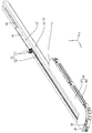
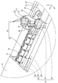
- the slide wiring device 10 includes a wire harness routing device 11, a rail 12, and a slider 13.
- the slide wiring device 10 of the present embodiment is for wiring the wire harness 15 between a vehicle body (not shown) of a vehicle (not shown) such as a car and the seat 14.
- the X direction in FIG. 1 will be described as right, the Y direction as front, and the Z direction as upper.
- only one member may be given a reference numeral, and the other members may be omitted.
- the seat 14 is slidable in the front-rear direction with respect to a metal rail 12 fixed by bolting or the like on the floor of the passenger compartment of the vehicle body.
- the seat 14 is provided with various electric components such as, for example, an electric reclining device, a seat heater, a sensor that detects the presence or absence of seating of an occupant, and a sensor that detects the presence or absence of a seat belt.
- the seat 14 is attached to a slider 13 slidably disposed on the rail 12.
- the wire harness 15 is wired on the floor of the vehicle body (below the mats and panels, etc.) and under the floor, and is connected to a device such as an electronic control unit (ECU) on the vehicle body side. Power supply and transmission / reception of signals between the device on the vehicle body side and the electrical components of the seat 14 are performed via the wire harness 15.
- ECU electronice control unit
- the wire harness 15 wired between the seat 14 and the vehicle body is inserted into the rail 12 below the seat 14 and the case 16 as shown in FIG. 2.
- the wire harness 15 includes a plurality of (four in the present embodiment) electric wires 17 and an exterior body 18 covering the plurality of electric wires 17.
- Each of the electric wires 17 has a metal conductor portion covered with an insulating layer, and is connected to various electrical components provided on the sheet 14.
- the exterior body 18 is made of insulating synthetic resin and extends in a band shape so as to cover the electric wire 17.
- the plurality of electric wires 17 are sheathed by the sheath 18.
- the exterior body 18 is formed by connecting a plurality of cylindrical units 19 with hinges 20 integrally formed with the units 19.
- the exterior body 18 is formed to be bendable at the hinge 20.
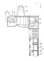
- the wire harness wiring apparatus 11 can detachably attach the wire harness 15, the case 16 for housing the wire harness 15, the protector 21 attached to the wire harness 15 drawn from the case 16, and the case 16 and the protector 21. And engaging means 22 for engaging.
- the material forming the case 16 is appropriately selected as necessary, such as a synthetic resin or a metal.
- the case 16 is provided with a bracket 23.
- a bolt (not shown) is inserted into the through hole 24 passing through the bracket 23, and the case 16 is fixed to the vehicle body by screwing the bolt to the vehicle body.
- the case 16 is elongated in the front-rear direction, and slightly protrudes leftward from the front end, and has a substantially J shape as viewed from above.
- the case 16 includes a lower case 26 which opens upward, and an upper case 27 which is attached to the lower case 26 from above and covers the lower case 26.
- the upper case 27 has substantially the same shape as the opening portion of the upper end edge of the lower case 26.
- the lower case 26 and the upper case 27 can be integrally assembled by resiliently locking the locking claw 28 formed on the side wall of the upper case 27 to the locking piece 29 formed on the side wall of the lower case 26. It has become.
- an opening 30 that opens rearward is formed at a position near the left.
- the wire harness 15 is led out of the case 16 or introduced into the case 16 from the opening 30.
- the cross-sectional shape of the opening 30 is larger than the cross-sectional shape of the exterior body 18 so that the exterior body 18 can be easily inserted through the opening 30.
- the electric wire 17 sheathed by the exterior body 18 is led out from the opening 30 to the rear.
- a protector 21 made of synthetic resin is disposed at the rear end portion of the exterior body 18.
- the protector 21 is integrally formed by the resilient engagement between the lock portion 33 formed on one side of the divisible first member 31 and the second member 32 and the lock receiving portion 34 formed on the other side. It is assembled.
- the end portion of the exterior body 18 is sandwiched between the first member 31 and the second member 32 so that the exterior body 18 and the protector 21 are integrally assembled.
- the protector 21 has a cylindrical portion 35 extending upward and opening upward. From the upper end portion of the cylindrical portion 35, the electric wire 17 led out from the exterior body 18 is led upward.
- the rails 12 are made of metal, and a pair of the rails 12 is provided on the floor for each sheet 14.
- a metal which comprises the rail 12 arbitrary metals, such as stainless steel, aluminum, aluminum alloy, etc. can be used suitably as needed.
- FIG. 1 only the rail 12 disposed on the right side is illustrated among the pair of rails 12.
- the rail 12 can be formed by a known method such as extrusion molding, die casting, bending, welding and the like.
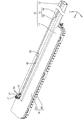
- the rail 12 linearly extends in the front-rear direction, and as shown in FIG. 4, an insertion hole 36 through which the slider 13 is inserted penetrates in the front-rear direction.
- the insertion hole 36 has a substantially rectangular shape corresponding to the cross-sectional shape of the slider 13.
- the slider 13 is slidably disposed in the insertion hole 36 in the front-rear direction.
- the rail 12 includes a bottom wall 37 extending in the front-rear direction, a pair of side walls 38 rising upward from the left and right side edges of the bottom wall 37, and an upper wall 39 extending inward in the left-right direction from the upper end edge of the side wall 38 Have.
- a through groove 40 communicating with the outside is formed in the upper wall 39 at a position above the insertion hole 36.
- the side wall 38 has a shape that is expanded in the left-right direction at a position slightly above the lower end.
- the bottom wall 37 is provided with fixing means for fixing to a vehicle.
- a fixing means although a bolt is illustrated, for example, it is not limited to a bolt.
- the slider 13 is made of, for example, synthetic resin or metal, and is slidable in the insertion hole 36 of the rail 12, and as shown in FIG. 4, the horizontally long insertion portion 41 fitted in the insertion hole 36. And a mounting portion 42 protruding upward in a plate shape from the upper surface of the insertion portion 41.
- the mounting portion 42 is formed over the entire length of the slider 13 and is fixed to the seat 14 by a known means such as a bolt.
- the mounting portion 42 slides between cuts formed in a mat or the like on the floor.
- the engagement means 22 corresponds to the engagement portion 43 formed extending rearward from the hole edge of the opening 30 of the case 16 and the front end portion of the protector 21 and corresponding to the engagement portion 43. Is the engaged portion 44 formed to extend forward from the position shown in FIG.
- the engaging portion 43 is formed at the right edge of the hole edge of the opening 30 of the case 16.
- the provision of the engaging portion 43 at the hole edge of the opening 30 includes the case where the engaging portion 43 is formed so as to extend continuously from the hole edge of the opening 30, and This includes the case where the joint portion 43 is provided close enough to be recognized as being formed substantially at the hole edge of the opening 30.
- the engaging portion 43 has a base wall 45 extending in the front-rear direction. The wall surface of the base wall 45 extends in the vertical direction. As shown in FIGS.
- the right side surface of the base wall 45 protrudes rightward from the upper end edge, the rear end edge, and the lower end edge, and the side edge of the engaged portion 44
- a groove 46 which can be accommodated is formed.
- the upper end edge, the front end edge, and the lower end edge of the engaged portion 44 of the protector 21 are inserted into the space enclosed by the base wall 45 and the groove 46.
- an engagement protrusion 47 that protrudes leftward is provided.
- a reinforcing rib 48 extending in the front-rear direction and projecting rightward is provided on the right side surface.
- the engaged portion 44 is formed to extend in the front-rear direction from the side wall 38 on the right side of the rear end portion of the protector 21.
- the engaged portion 44 is in the form of a plate that can be elastically deformed in the left-right direction.
- An engagement groove 49 extending in the vertical direction is formed on the left side surface of the engaged portion 44.
- the cylindrical portion 35 of the protector 21 is positioned rearward of the front end of the rail 12. In other words, at least the cylindrical portion 35 of the protector 21 is located in an area where the slider 13 can slide on the rail 12.
- the cylindrical portion 35 of the protector 21 is formed with a pair of temporary locking portions 50 that project rearward from the rear end portion.
- the temporary locking portion 50 has a plate shape in which the plate surface extends in the vertical direction.
- a protector side through hole 51 which penetrates the temporary locking portion 50 in the left-right direction is formed.
- the distance between the pair of temporary locking portions 50 in the left-right direction is set to be equal to or slightly larger than the width dimension of the mounting portion 42 of the slider 13 in the left-right direction.
- the mounting portion 42 of the slider 13 can enter between the pair of temporary locking portions 50.
- the mounting portion 42 of the slider 13 is mounted at a position corresponding to the protector side through hole 51.
- a slider side through hole 52 penetrating the portion 42 is formed.
- the bolt 53 is inserted into the slider side through hole 52 and the protector side through hole 51 in a state where the mounting portion 42 is advanced between the pair of temporary locking portions 50, and the bolt 53 is screwed with the nut 54.
- the protector 21 and the slider 13 are fixed (see FIG. 17).
- the electric wire 17 is inserted into the inside of the tubular portion 35 of the exterior body 18.
- the protector 21 is attached to one end of the exterior body 18 by holding the one end of the exterior body 18 and the electric wire 17 drawn from this end by the first member 31 and the second member 32. Do. Thereby, the wire harness 15 is completed.
- the wire harness 15 is accommodated in the lower case 26 in a state where the upper case 27 is not assembled. Next, the upper case 27 is assembled to the lower case 26. At this time, the end of the wire harness 15 is led out from the opening 30 of the case 16.
- the engaged portion 44 of the protector 21 is made to approach the engaging portion 43 provided in the case 16 from the rear to the front.
- the left and right side edges of the front end of the engaged portion 44 enter the inside of the groove 46 formed in the left and right side edges of the rear end of the engaging portion 43.
- the engaged portion 44 When the engaged portion 44 is further moved forward, the front end portion of the engaged portion 44 rides on the engaging projection 47 of the engaging portion 43. Thereby, the engaged portion 44 elastically deforms to the left. Further, when the engaged portion 44 is moved forward, the engaged portion 44 is returned and deformed, and the engaging protrusion 47 of the engaging portion 43 fits inside the engaging groove 49 of the engaged portion 44. Thereby, the engaging portion 43 and the engaged portion 44 are engaged in the front-rear direction, and the protector 21 is restricted from moving rearward with respect to the case 16. Thereby, the wire harness routing device 11 is completed (see FIG. 9).
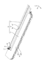
- the rail 12 is processed into a predetermined shape, and the insertion portion 41 of the slider 13 is inserted into the insertion hole 36 of the rail 12, and the mounting portion 42 of the slider 13 is disposed in the through groove 40 of the rail 12.
- the slider 13 is assembled to the rail 12 in a state where it can slide in the front-rear direction with respect to the rail 12.
- the wire harness routing device 11 and the rail 12 assembled with the slider 13 are fixed at a predetermined position of the vehicle.
- the opening 30 of the case 16 and the front end of the rail 12 are disposed to face each other.
- the slider 13 is moved forward.
- the attachment portion 42 of the slider 13 enters between the pair of temporary locking portions 50 provided on the protector 21.
- the slider 13 and the protector 21 are temporarily locked.
- the protector 21 and the slider 13 are fixed by inserting the bolt 53 into the protector side through hole 51 and the slider side through hole 52 and screwing the shaft portion of the bolt 53 to the nut 54 ( 16 and 17).
- the slider 13 is pulled backward.
- the protector 21 fixed to the slider 13 is also pulled backward.
- the engaging projection 47 of the engaging portion 43 provided on the case 16 abuts on the front wall of the engaging groove 49 provided on the engaged portion 44 of the protector 21 from behind.
- the engaged portion 44 is also pulled backward by following the engaged portion 44, the engaged portion 44 rides on the engaging projection 47, and the engaged portion 44 elastically deforms to the right. Further, by pulling the slider 13 backward, the engaged portion 44 passes over the engaging protrusion 47 and is returned and deformed, and the engagement between the engaging portion 43 and the engaged portion 44 is released. Thereby, the slider 13 can slide in the front-rear direction (see FIG.
- the wire harness 15 is attached to the protector 21 fixed to the slider 13. Therefore, as the slider 13 moves back and forth, the wire harness 15 receives a force in the front-rear direction, and moves backward from the opening 30 of the case 16 It is derived or introduced into the case 16 from the opening 30. Thereby, the slide wiring device 10 is completed.
- the wire harness wiring apparatus 11 is a case 16 in which the wire harness 15 and the wire harness 15 are accommodated, and the opening portion 30 is provided so that the wire harness 15 can be derived or introduced from the opening portion 30. And a protector 21 attached to the wire harness 15 led out from the opening 30, and engaging means 22 for detachably engaging the case 16 and the protector 21.
- the wire harness 15 derived from the opening 30 of the case 16 can be engaged with the case 16. Thereby, when transporting the wire harness routing apparatus 11, the wire harness 15 derived
- the engagement means 22 are the engagement portion 43 provided in the case 16 and the engaged portion 44 provided in the protector 21. Thereby, compared with the case where the engagement means 22 is comprised by the member different from case 16 and the protector 21, a number of parts can be decreased.
- the engagement portion 43 is provided at the hole edge of the opening 30.
- the protector 21 approaches the opening 30 of the case 16 by pushing the wire harness 15 in a state of being pulled out of the case 16 from the opening 30 into the case 16. Since the engaging portion 43 that engages with the engaged portion 44 of the protector 21 is provided at the hole edge of the opening 30, the operation of pushing the wire harness 15 into the case 16 and the hole of the opening 30 An operation of bringing the protector 21 closer to the engagement portion 43 formed at the edge can be performed simultaneously. As a result, positioning between the protector 21 and the case 16 can be easily performed.
- the direction in which the engagement between the case 16 and the protector 21 by the engagement means 22 is released is parallel to the direction in which the wire harness 15 is led out from the opening 30.
- the engagement between the case 16 and the protector 21 can be released by pulling the wire harness 15 along the direction in which the wire harness 15 is led out from the opening 30.
- the engagement between the case 16 and the protector 21 can be released by a simple method of pulling the wire harness 15.
- one end is disposed in the wire harness wiring device 11 and the opening 30 of the case 16, and along the direction in which the wire harness 15 is drawn out from the opening 30.
- a slider 13 which is disposed slidably with respect to the rail 12 and which is provided with a protector 21 and a T-fixed slider.
- the wire harness routing device 11 can be applied to the slide wiring device 10.
- the protector 21 fixed to the slider 13 can also be moved.
- the wire harness 15 can be pulled through the protector 21 fixed to the slider 13 by moving the slider 13 along the direction in which the wire harness 15 is led out from the opening 30.
- the engagement between the case 16 and the protector 21 can be released.
- the engagement between the case 16 and the protector 21 can be released by a simple method of sliding the slider 13.
- At least a part of the protector 21 is located in a region where the slider 13 can slide in a state where the protector 21 and the case 16 are engaged.
- One of the two has a temporary locking portion 50 which temporarily locks with the other.
- the assembling operation may need to be performed in the region inside the rail 12. In this case, since the work is performed in a narrow space inside the rail 12, the work efficiency is reduced. In order to avoid this, it is conceivable to once assemble the slider 13 and the protector 21 after removing the slider 13 from the rail 12 and attach the slider 13 to the rail 12 again, but the operation becomes complicated.
- the protector 21 and the slider 13 can be temporarily locked.
- the protector 21 and the slider 13 can be fixed in a state where the protector 21 and the slider 13 are temporarily locked, so that the efficiency of fixing work between the protector 21 and the slider 13 can be improved.
- the engaging means 22 is the engaging portion 43 provided in the case 16 and the engaged portion 44 provided in the protector 21.
- the present invention is not limited to this.
- the case 16 and the protector 21 may be separate members, and may be engaged with each other by sandwiching the case 16 and the protector 21 in an overlapping state.
- the engaging portion 43 provided in the protector 21 is configured to extend along the direction in which the electric wire 17 is led out from the case 16.
- the engaged portion 44 may be extended along the direction in which the electric wire 17 is led out of the case 16.
- the direction in which the engagement between the case 16 and the protector 21 by the engagement means 22 is opened is parallel to the direction in which the electric wire 17 is led out from the opening 30.
- the engagement means 22 is a clip
- the clip may be separated from the case 16 and the protector 21 along a direction intersecting with the direction in which the electric wire 17 is led out from the opening 30.
- the temporary locking portion 50 for temporarily locking the protector 21 and the slider 13 may be omitted.
- the sheet 14 is attached to the slider 13.
- the present invention is not limited to this.
- An optional member that slides with respect to the rail 12 such as a slide door is attached to the slider 13. It is good also as composition.
- the wire harness 15 includes four electric wires 17 in the present embodiment, the present invention is not limited to this.
- the wire harness 15 includes two to three or five or more electric wires 17. It may be
Landscapes
- Engineering & Computer Science (AREA)
- Mechanical Engineering (AREA)
- Architecture (AREA)
- Civil Engineering (AREA)
- Structural Engineering (AREA)
- Aviation & Aerospace Engineering (AREA)
- Transportation (AREA)
- Electric Cable Arrangement Between Relatively Moving Parts (AREA)
- Seats For Vehicles (AREA)
- Details Of Indoor Wiring (AREA)
Priority Applications (3)
| Application Number | Priority Date | Filing Date | Title |
|---|---|---|---|
| DE112018004013.5T DE112018004013T5 (de) | 2017-08-07 | 2018-07-26 | Kabelstrangführungsvorrichtung und verschiebbare Verkabelungsvorrichtung |
| CN201880048217.6A CN110959238B (zh) | 2017-08-07 | 2018-07-26 | 线束布设装置及滑动布线装置 |
| US16/636,663 US11203308B2 (en) | 2017-08-07 | 2018-07-26 | Wire harness routing device and slide wiring device |
Applications Claiming Priority (2)
| Application Number | Priority Date | Filing Date | Title |
|---|---|---|---|
| JP2017152205A JP6760228B2 (ja) | 2017-08-07 | 2017-08-07 | ワイヤーハーネス配索装置、及びスライド配線装置 |
| JP2017-152205 | 2017-08-07 |
Publications (1)
| Publication Number | Publication Date |
|---|---|
| WO2019031254A1 true WO2019031254A1 (ja) | 2019-02-14 |
Family
ID=65271164
Family Applications (1)
| Application Number | Title | Priority Date | Filing Date |
|---|---|---|---|
| PCT/JP2018/028024 Ceased WO2019031254A1 (ja) | 2017-08-07 | 2018-07-26 | ワイヤーハーネス配索装置、及びスライド配線装置 |
Country Status (5)
| Country | Link |
|---|---|
| US (1) | US11203308B2 (https=) |
| JP (1) | JP6760228B2 (https=) |
| CN (1) | CN110959238B (https=) |
| DE (1) | DE112018004013T5 (https=) |
| WO (1) | WO2019031254A1 (https=) |
Families Citing this family (5)
| Publication number | Priority date | Publication date | Assignee | Title |
|---|---|---|---|---|
| JP2021069153A (ja) * | 2019-10-18 | 2021-04-30 | 矢崎総業株式会社 | スライド給電装置 |
| FR3114057B1 (fr) * | 2020-09-15 | 2022-12-02 | Faurecia Sieges Dautomobile | Dispositif de guidage de câble électrique pour glissière de siège de véhicule automobile |
| KR102931324B1 (ko) * | 2020-11-04 | 2026-02-26 | 현대자동차주식회사 | 차량용 시트레일 |
| WO2023105428A1 (de) * | 2021-12-07 | 2023-06-15 | Adient Us Llc | Kabelumlenkvorrichtung und sitzlängsverstelleinrichtung mit einer kabelumlenkvorrichtung |
| CN115275875A (zh) * | 2022-08-09 | 2022-11-01 | 南京中车浦镇城轨车辆有限责任公司 | 一种分线箱引上线束布线通用定位装置 |
Citations (3)
| Publication number | Priority date | Publication date | Assignee | Title |
|---|---|---|---|---|
| JP2012191830A (ja) * | 2011-02-23 | 2012-10-04 | Yazaki Corp | ハーネス配索装置 |
| JP2017022806A (ja) * | 2015-07-07 | 2017-01-26 | 住友電装株式会社 | スライドシート用のワイヤハーネス配索装置 |
| JP2017070137A (ja) * | 2015-10-01 | 2017-04-06 | 株式会社オートネットワーク技術研究所 | スライド配線装置 |
Family Cites Families (11)
| Publication number | Priority date | Publication date | Assignee | Title |
|---|---|---|---|---|
| US7000967B2 (en) * | 2002-12-27 | 2006-02-21 | Ts Tech Co., Ltd. | Slidable vehicle seat provided with automotive electronic parts |
| JP4095940B2 (ja) * | 2003-08-13 | 2008-06-04 | 矢崎総業株式会社 | スライドシート用給電装置 |
| US7730669B2 (en) * | 2003-09-22 | 2010-06-08 | Sumitomo Wiring Systems, Ltd. | Device for guiding a conductor path for slide door |
| JP4263684B2 (ja) * | 2004-08-06 | 2009-05-13 | 矢崎総業株式会社 | スライド用給電装置 |
| JP4403091B2 (ja) * | 2005-03-03 | 2010-01-20 | 矢崎総業株式会社 | 給電装置 |
| JP2009194990A (ja) * | 2008-02-13 | 2009-08-27 | Yazaki Corp | スライド構造体用の給電装置 |
| CN102216121B (zh) * | 2008-12-16 | 2013-10-16 | 矢崎总业株式会社 | 线束布设装置 |
| JP5248436B2 (ja) * | 2009-07-22 | 2013-07-31 | 矢崎総業株式会社 | ワイヤハーネス配索装置 |
| JP5356937B2 (ja) * | 2009-07-22 | 2013-12-04 | 矢崎総業株式会社 | ワイヤハーネス配索装置 |
| JP2012045994A (ja) | 2010-08-25 | 2012-03-08 | Sumitomo Wiring Syst Ltd | スライド配線装置 |
| JP6390906B2 (ja) * | 2014-12-03 | 2018-09-19 | 株式会社オートネットワーク技術研究所 | ワイヤハーネスの取り付け構造および配線ユニット |
-
2017
- 2017-08-07 JP JP2017152205A patent/JP6760228B2/ja active Active
-
2018
- 2018-07-26 DE DE112018004013.5T patent/DE112018004013T5/de active Pending
- 2018-07-26 CN CN201880048217.6A patent/CN110959238B/zh active Active
- 2018-07-26 US US16/636,663 patent/US11203308B2/en active Active
- 2018-07-26 WO PCT/JP2018/028024 patent/WO2019031254A1/ja not_active Ceased
Patent Citations (3)
| Publication number | Priority date | Publication date | Assignee | Title |
|---|---|---|---|---|
| JP2012191830A (ja) * | 2011-02-23 | 2012-10-04 | Yazaki Corp | ハーネス配索装置 |
| JP2017022806A (ja) * | 2015-07-07 | 2017-01-26 | 住友電装株式会社 | スライドシート用のワイヤハーネス配索装置 |
| JP2017070137A (ja) * | 2015-10-01 | 2017-04-06 | 株式会社オートネットワーク技術研究所 | スライド配線装置 |
Also Published As
| Publication number | Publication date |
|---|---|
| DE112018004013T5 (de) | 2020-05-07 |
| JP6760228B2 (ja) | 2020-09-23 |
| CN110959238A (zh) | 2020-04-03 |
| JP2019033570A (ja) | 2019-02-28 |
| CN110959238B (zh) | 2021-08-20 |
| US11203308B2 (en) | 2021-12-21 |
| US20210146864A1 (en) | 2021-05-20 |
Similar Documents
| Publication | Publication Date | Title |
|---|---|---|
| WO2019031254A1 (ja) | ワイヤーハーネス配索装置、及びスライド配線装置 | |
| JP6032125B2 (ja) | スライドシート用のワイヤハーネス配索装置 | |
| JP6436039B2 (ja) | スライド配線装置 | |
| JP5523568B2 (ja) | ワイヤハーネス配索装置 | |
| US10836332B2 (en) | Connection structure connecting conduit to protector, and wire harness | |
| JP2015071333A (ja) | ドア用ワイヤーハーネスモジュール | |
| US20200215999A1 (en) | Wire harness routing device | |
| JP6056732B2 (ja) | スライドシート用ワイヤハーネスの配索装置 | |
| JP6610403B2 (ja) | ワイヤーハーネス配索装置 | |
| JP5552388B2 (ja) | ワイヤハーネス配索装置 | |
| JP2017093016A (ja) | ワイヤーハーネス配索装置 | |
| JP6618040B2 (ja) | 車載部品 | |
| JP5798723B2 (ja) | ワイヤハーネス配索装置 | |
| JP2016199063A (ja) | 車載用給電装置 | |
| JP5178174B2 (ja) | ワイヤハーネス用プロテクタ | |
| JP5939200B2 (ja) | スライドシートとスライダとの連結構造 | |
| JP7135774B2 (ja) | カウルサイドトリムの取付構造 | |
| JPH08322128A (ja) | 電線カバー付電気接続箱 | |
| WO2021059873A1 (ja) | 外装体、およびワイヤーハーネス | |
| JP6702912B2 (ja) | 電線の保護ケース、及び、スライドシート | |
| WO2020012882A1 (ja) | 配線装置、及びスライド配線装置 | |
| JP6052067B2 (ja) | スライドシート用のワイヤハーネス配索装置 | |
| JP2022099344A (ja) | 給電装置及び給電ケース | |
| JP4770541B2 (ja) | ワイヤハーネスプロテクタ | |
| WO2021049344A1 (ja) | ワイヤーハーネス配索装置 |
Legal Events
| Date | Code | Title | Description |
|---|---|---|---|
| 121 | Ep: the epo has been informed by wipo that ep was designated in this application |
Ref document number: 18843043 Country of ref document: EP Kind code of ref document: A1 |
|
| 122 | Ep: pct application non-entry in european phase |
Ref document number: 18843043 Country of ref document: EP Kind code of ref document: A1 |