WO2019031209A1 - Noyau magnétique en poudre et composant électromagnétique - Google Patents
Noyau magnétique en poudre et composant électromagnétique Download PDFInfo
- Publication number
- WO2019031209A1 WO2019031209A1 PCT/JP2018/027436 JP2018027436W WO2019031209A1 WO 2019031209 A1 WO2019031209 A1 WO 2019031209A1 JP 2018027436 W JP2018027436 W JP 2018027436W WO 2019031209 A1 WO2019031209 A1 WO 2019031209A1
- Authority
- WO
- WIPO (PCT)
- Prior art keywords
- coating film
- insulating resin
- resin coating
- green compact
- powder
- Prior art date
Links
Images

Classifications
-
- H—ELECTRICITY
- H01—ELECTRIC ELEMENTS
- H01F—MAGNETS; INDUCTANCES; TRANSFORMERS; SELECTION OF MATERIALS FOR THEIR MAGNETIC PROPERTIES
- H01F1/00—Magnets or magnetic bodies characterised by the magnetic materials therefor; Selection of materials for their magnetic properties
- H01F1/01—Magnets or magnetic bodies characterised by the magnetic materials therefor; Selection of materials for their magnetic properties of inorganic materials
- H01F1/03—Magnets or magnetic bodies characterised by the magnetic materials therefor; Selection of materials for their magnetic properties of inorganic materials characterised by their coercivity
- H01F1/12—Magnets or magnetic bodies characterised by the magnetic materials therefor; Selection of materials for their magnetic properties of inorganic materials characterised by their coercivity of soft-magnetic materials
- H01F1/14—Magnets or magnetic bodies characterised by the magnetic materials therefor; Selection of materials for their magnetic properties of inorganic materials characterised by their coercivity of soft-magnetic materials metals or alloys
- H01F1/20—Magnets or magnetic bodies characterised by the magnetic materials therefor; Selection of materials for their magnetic properties of inorganic materials characterised by their coercivity of soft-magnetic materials metals or alloys in the form of particles, e.g. powder
- H01F1/22—Magnets or magnetic bodies characterised by the magnetic materials therefor; Selection of materials for their magnetic properties of inorganic materials characterised by their coercivity of soft-magnetic materials metals or alloys in the form of particles, e.g. powder pressed, sintered, or bound together
- H01F1/24—Magnets or magnetic bodies characterised by the magnetic materials therefor; Selection of materials for their magnetic properties of inorganic materials characterised by their coercivity of soft-magnetic materials metals or alloys in the form of particles, e.g. powder pressed, sintered, or bound together the particles being insulated
- H01F1/26—Magnets or magnetic bodies characterised by the magnetic materials therefor; Selection of materials for their magnetic properties of inorganic materials characterised by their coercivity of soft-magnetic materials metals or alloys in the form of particles, e.g. powder pressed, sintered, or bound together the particles being insulated by macromolecular organic substances
-
- B—PERFORMING OPERATIONS; TRANSPORTING
- B22—CASTING; POWDER METALLURGY
- B22F—WORKING METALLIC POWDER; MANUFACTURE OF ARTICLES FROM METALLIC POWDER; MAKING METALLIC POWDER; APPARATUS OR DEVICES SPECIALLY ADAPTED FOR METALLIC POWDER
- B22F3/00—Manufacture of workpieces or articles from metallic powder characterised by the manner of compacting or sintering; Apparatus specially adapted therefor ; Presses and furnaces
- B22F3/24—After-treatment of workpieces or articles
-
- H—ELECTRICITY
- H01—ELECTRIC ELEMENTS
- H01F—MAGNETS; INDUCTANCES; TRANSFORMERS; SELECTION OF MATERIALS FOR THEIR MAGNETIC PROPERTIES
- H01F27/00—Details of transformers or inductances, in general
- H01F27/24—Magnetic cores
- H01F27/255—Magnetic cores made from particles
-
- H—ELECTRICITY
- H01—ELECTRIC ELEMENTS
- H01F—MAGNETS; INDUCTANCES; TRANSFORMERS; SELECTION OF MATERIALS FOR THEIR MAGNETIC PROPERTIES
- H01F27/00—Details of transformers or inductances, in general
- H01F27/28—Coils; Windings; Conductive connections
-
- H—ELECTRICITY
- H01—ELECTRIC ELEMENTS
- H01F—MAGNETS; INDUCTANCES; TRANSFORMERS; SELECTION OF MATERIALS FOR THEIR MAGNETIC PROPERTIES
- H01F3/00—Cores, Yokes, or armatures
- H01F3/08—Cores, Yokes, or armatures made from powder
-
- H—ELECTRICITY
- H01—ELECTRIC ELEMENTS
- H01F—MAGNETS; INDUCTANCES; TRANSFORMERS; SELECTION OF MATERIALS FOR THEIR MAGNETIC PROPERTIES
- H01F41/00—Apparatus or processes specially adapted for manufacturing or assembling magnets, inductances or transformers; Apparatus or processes specially adapted for manufacturing materials characterised by their magnetic properties
- H01F41/02—Apparatus or processes specially adapted for manufacturing or assembling magnets, inductances or transformers; Apparatus or processes specially adapted for manufacturing materials characterised by their magnetic properties for manufacturing cores, coils, or magnets
- H01F41/0206—Manufacturing of magnetic cores by mechanical means
- H01F41/0246—Manufacturing of magnetic circuits by moulding or by pressing powder
-
- H—ELECTRICITY
- H02—GENERATION; CONVERSION OR DISTRIBUTION OF ELECTRIC POWER
- H02K—DYNAMO-ELECTRIC MACHINES
- H02K1/00—Details of the magnetic circuit
- H02K1/02—Details of the magnetic circuit characterised by the magnetic material
-
- H—ELECTRICITY
- H01—ELECTRIC ELEMENTS
- H01F—MAGNETS; INDUCTANCES; TRANSFORMERS; SELECTION OF MATERIALS FOR THEIR MAGNETIC PROPERTIES
- H01F1/00—Magnets or magnetic bodies characterised by the magnetic materials therefor; Selection of materials for their magnetic properties
- H01F1/01—Magnets or magnetic bodies characterised by the magnetic materials therefor; Selection of materials for their magnetic properties of inorganic materials
- H01F1/03—Magnets or magnetic bodies characterised by the magnetic materials therefor; Selection of materials for their magnetic properties of inorganic materials characterised by their coercivity
- H01F1/12—Magnets or magnetic bodies characterised by the magnetic materials therefor; Selection of materials for their magnetic properties of inorganic materials characterised by their coercivity of soft-magnetic materials
- H01F1/14—Magnets or magnetic bodies characterised by the magnetic materials therefor; Selection of materials for their magnetic properties of inorganic materials characterised by their coercivity of soft-magnetic materials metals or alloys
- H01F1/20—Magnets or magnetic bodies characterised by the magnetic materials therefor; Selection of materials for their magnetic properties of inorganic materials characterised by their coercivity of soft-magnetic materials metals or alloys in the form of particles, e.g. powder
- H01F1/22—Magnets or magnetic bodies characterised by the magnetic materials therefor; Selection of materials for their magnetic properties of inorganic materials characterised by their coercivity of soft-magnetic materials metals or alloys in the form of particles, e.g. powder pressed, sintered, or bound together
- H01F1/24—Magnets or magnetic bodies characterised by the magnetic materials therefor; Selection of materials for their magnetic properties of inorganic materials characterised by their coercivity of soft-magnetic materials metals or alloys in the form of particles, e.g. powder pressed, sintered, or bound together the particles being insulated
Definitions
- the present disclosure relates to a dust core and an electromagnetic component.
- This application claims the priority based on Japanese Patent Application No. 2017-156041 filed on Aug. 10, 2017, and incorporates all the contents described in the Japanese Patent Application.
- electromagnetic components such as a motor which arrange
- a powder magnetic core has been used as a magnetic core of an electromagnetic component.
- a dust core is constituted by a green compact obtained by pressure molding soft magnetic powder.
- Patent Document 1 discloses a green compact comprising a compact (green compact) obtained by pressure molding a coated soft magnetic powder having an insulating coating on the particle surface of the soft magnetic powder, and an anticorrosive layer covering the entire surface of the compact.
- a magnetic core is disclosed.
- the dust core according to the present disclosure is A green compact containing soft magnetic powder, And an insulating resin coating film covering a part of the surface of the green compact,
- the ratio of the area of the insulating resin coating film to the surface area of the green compact is 85% or less, and the maximum depth of irregularities on the surface of the insulating resin coating film is 20 ⁇ m or less.
- the electromagnetic component according to the present disclosure is The dust core according to the present disclosure, and a coil disposed on the dust core.
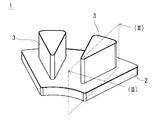
- FIG. 1 is a schematic explanatory view showing an example of a dust core according to an embodiment of the present disclosure.
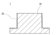
- FIG. 2 is a cross-sectional view taken along line (II)-(II) in FIG.
- FIG. 3 is a diagram for explaining a method of measuring the maximum depth of the unevenness.
- the means for securing the insulation between the powder magnetic core and the coil for example, it is conceivable to coat a resin on the surface of the powder compact to form an insulating resin coating film.
- the insulating resin coating film is formed, it is possible to arrange the coil directly on the dust core, and it is not necessary to increase the current flowing through the coil more than necessary, and the coil current can be reduced.
- reduction of a number of parts and simplification of an assembly operation can be achieved.
- the insulating resin coating film is required to have high electrical insulation properties, and it is desirable that no pinholes or locally thin portions be present.
- a pinhole or a locally thin portion exists in the insulating resin coating film, the portion becomes a starting point of the dielectric breakdown, and the electrical insulation (voltage resistance) is deteriorated.
- Another object of the present invention is to provide an electromagnetic component that can ensure electrical insulation between a dust core and a coil by means of an insulating resin film provided on the dust core.
- the dust core of the present disclosure includes an insulating resin coating film having high electrical insulation.
- the electromagnetic component of the present disclosure can ensure electrical insulation between the dust core and the coil by the insulating resin film provided on the dust core.
- the insulating resin coating film can be formed by applying a resin on the surface of the green compact and then heat treating it to solidify the resin.
- the insulating resin coating film is formed following the surface of the green compact, asperities are also formed on the surface of the insulating resin coating film.
- the unevenness (roughness) of the green compact surface is large, the thickness of the resin may not be uniform when the green compact surface is coated with a resin, and a thin portion of the resin may be formed. For example, the resin may intrude into a portion (valley portion) where the unevenness of the green compact surface is deep, and the resin may become thin at that portion.
- the film thickness of the insulating resin coating film may be extremely thin at a deep portion of the unevenness to form a pinhole.
- the present inventors found that when the insulating resin coating film is formed not on the entire surface of the green compact surface but on a part of the surface and the depth of the unevenness on the insulating resin coating film surface is small, It has been found that there is no pinhole or locally thin portion in the film, and an insulating resin film with high electrical insulation can be obtained.
- embodiments of the present disclosure will be listed and described.
- the dust core according to the present disclosure is A green compact containing soft magnetic powder, And an insulating resin coating film covering a part of the surface of the green compact,
- the ratio of the area of the insulating resin coating film to the surface area of the green compact is 85% or less, and the maximum depth of irregularities on the surface of the insulating resin coating film is 20 ⁇ m or less.
- the powder magnetic core In the powder magnetic core, a part of the surface of the powder compact is covered with an insulating resin coating film.
- the area ratio of the insulating resin coating film to the surface of the green compact is 85% or less.
- the resin in order to form the insulating resin coating film on a part of the surface of the green compact, the resin is coated not on the entire surface of the green compact but on a part thereof. That is, when coating a resin on the powder compact surface to form an insulating resin coating film, there are a coated surface on which the resin is coated and a non-painted surface on which the resin is not coated on the powder compact surface. That is, the entire surface of the green compact is not covered with the resin.
- the insulating resin coating film may be formed on at least a portion of the green compact surface requiring electrical insulation.
- the lower limit of the area ratio of the insulating resin coating film is, for example, 25% or more.
- the possibility that the thin portion of the film thickness is locally formed in the insulating resin coating film is possible because the maximum depth of the unevenness of the insulating resin coating film surface is 20 ⁇ m or less Low. This is because the maximum depth of the unevenness of the insulating resin coating film surface is 20 ⁇ m or less, and the unevenness (roughness) of the green compact surface is small, so when the resin is coated on the green compact surface, the resin is thin. It is because it is hard to form a part.
- the lower limit of the maximum depth of the unevenness of the insulating resin coating film surface is not particularly limited, but is, for example, 1 ⁇ m or more from the viewpoint of the surface properties of the green compact and the like. The measuring method of the largest depth of the unevenness
- the dust core does not have a pinhole or a locally thin portion formed in the insulating resin coating film, and is provided with the insulating resin coating film having high electrical insulation.
- the relative density of the above-mentioned powder compact is 90% or more, and it is mentioned that the maximum depth of unevenness of the above-mentioned powder compact surface is 50 micrometers or less.
- the upper limit of the relative density of the green compact is not particularly limited, but is, for example, 99% or less from the viewpoint of the production conditions of the green compact.
- the "relative density" as used herein means the actual density (the percentage of [measured density of green compact / true density of green compact]) to the true density.
- the true density is the density of the soft magnetic powder contained in the green compact.
- thickness of the above-mentioned insulating resin coat is 25 micrometers or more and 100 micrometers or less.
- the thickness of the insulating resin coating film is 25 ⁇ m or more, the electrical insulation of the insulating resin coating film can be sufficiently secured.
- the thickness of the insulating resin coating film is 100 ⁇ m or less, the insulating resin coating film does not become too thick, and the green compact and the coil can be disposed close to each other when the electromagnetic component is configured. Therefore, it is possible to reduce the current of the coil and to miniaturize the electromagnetic component.
- the electrical insulation (voltage resistance) of the insulating resin coating film is sufficiently high.
- the upper limit of the dielectric breakdown voltage of the insulating resin coating film is not particularly limited, but is, for example, 3000 V or less from the viewpoint of the insulating properties of the resin constituting the insulating resin coating film and the thickness (film thickness) of the coating film. The method of measuring the dielectric breakdown voltage of the insulating resin coating will be described later.
- the insulating resin coating film contains at least one resin of epoxy type, fluorine type and polyimide type.
- the insulating resin coating film is formed by containing a resin having electrical insulation. It is preferable that the resin constituting the insulating resin coating film has high electrical insulation and good adhesion to the green compact. Further, the resin constituting the insulating resin coating film preferably has high heat resistance because the powder magnetic core is in a high temperature state when the electromagnetic component is used. Epoxy-based, fluorine-based and polyimide-based resins are excellent in adhesion and heat resistance in addition to electrical insulating properties, and are suitable as resins constituting an insulating resin coating film.
- the insulating resin coating film is a filler comprising an oxide or a nitride containing at least one element selected from Mg, Si, Al, Mo, Ca, Ti and Zn. Can be mentioned.
- the insulating resin coating film contains the above-described filler, a plurality of fillers are dispersed and present in the insulating resin coating film, and the electrical insulation of the insulating resin coating film can be improved. Specifically, since the pinhole extending in the thickness direction of the insulating resin coating film is divided by the filler, generation of pinholes penetrating in the thickness direction of the coating film from the surface of the insulating resin coating film to the surface of the green compact Can be more effectively prevented.
- the filler made of an oxide or nitride containing at least one element selected from Mg, Si, Al, Mo, Ca, Ti and Zn has high electrical resistance, the insulating property of the resin is Contribute to the improvement of Furthermore, when the insulating resin coating film contains a filler, when the insulating resin coating film is formed on the surface of the corner portion of the green compact (especially when resin is coated), it is not solidified from the corner portion to the flat portion It is easy to control the movement of the resin. Therefore, it can suppress that the insulating resin coating film which covers the corner
- the green compact has a flat portion and a corner portion,
- the thickness of the insulating resin coating film covering the corner portion is 25 ⁇ m or more and 100 ⁇ m or less, It is mentioned that the thickness of the insulating resin coating film covering the flat portion is 0.7 times or more and 1.3 times or less the thickness of the insulating resin coating film covering the corner portion.
- the thickness of the insulating resin coating film covering the corner of the green compact is 25 ⁇ m or more, electrical insulation at the corner can be sufficiently secured.
- the thickness of the insulating resin coating film covering the corner portion is 100 ⁇ m or less, the insulating resin coating film at the corner portion does not become too thick. Therefore, when the electromagnetic component is formed, the green compact and the coil can be disposed close to each other, so that the current of the coil can be reduced, and the electromagnetic component can be miniaturized.
- the thickness of the insulating resin coating film covering the flat portion of the powder compact is 0.7 times or more and 1.3 times or less the thickness of the insulating resin coating film covering the corner portion, so that the electric portion in the flat portion is electrically It is possible to reduce the current of the coil and to miniaturize the electromagnetic component while securing the insulation.
- the above-mentioned powder compact has a phosphate film in the surface.
- the unevenness (roughness) of the green compact surface is reduced. This is because the green compact surface is sealed by phosphating the green compact to form a phosphate film on the surface. Moreover, the effect which improves the adhesiveness of insulating resin coating film can also be anticipated by having a phosphate film.
- the phosphate film include films such as zinc phosphates, iron phosphates, manganese phosphates, and calcium phosphates.
- the electromagnetic component according to the present disclosure is The dust core according to any one of the above (1) to (8), and a coil disposed on the dust core.
- the powder magnetic core according to the present disclosure described above is used as the electromagnetic component, and an insulating resin coating film having high electrical insulation is formed on the surface of the powder magnetic core. Therefore, the said electromagnetic component can ensure the electrical insulation between a dust core and a coil by the insulation resin coating film with which a dust core is equipped.
- an electromagnetic component a motor, a choke coil, a reactor etc. are mentioned, for example.
- FIG. 1 is a schematic perspective view of a dust core 1.
- FIG. 2 shows a cross section cut along line (II)-(II) shown in FIG.
- the powder magnetic core 1 includes a green compact 10 containing soft magnetic powder and an insulating resin coating film 20 covering a part of the surface of the green compact 10.
- One of the characteristics of the powder magnetic core 1 of the embodiment is that the ratio of the area of the insulating resin coating film 20 to the surface area of the green compact 10 is 85% or less, and the maximum depth of the unevenness of the surface of the insulating resin coating film 20 is The point is 20 ⁇ m or less.
- the configuration of the dust core 1 will be described in detail.
- the dust core 1 (powder compact 10) illustrated in FIG. 1 is a component constituting a part of a stator core used in an axial gap type motor, and has a fan-shaped yoke portion 2 and teeth portions protruding from the yoke portion 2. And 3.
- a stator core is configured by assembling the dust cores 1 as a set of six in an annular shape, and a coil (not shown) is wound and disposed on the outer periphery of each tooth portion 3.
- the powder magnetic core 1 a part of the surface of the green compact 10 is covered with the insulating resin coating film 20, and in this example, the outer peripheral surface of the teeth portion 3 in the surface of the green compact 10, and The upper surface of the yoke portion 2 from which the teeth portion 3 protrudes is covered with the insulating resin coating film 20.
- the shape of the dust core 1 can be appropriately selected according to the application and the like, and examples thereof include a cylindrical shape such as a cylindrical shape and a square cylinder shape, and a columnar shape such as a cylinder or a prism.
- the green compact 10 is manufactured, for example, by filling soft magnetic powder in a mold and pressing.
- the green compact 10 contains a soft magnetic powder.
- the soft magnetic powder is a powder made of a soft magnetic material.
- the soft magnetic powder is composed of a plurality of particles.
- As the soft magnetic material for example, pure iron (purity 99 mass% or more), Fe-Si-Al alloy (sendust), Fe-Si alloy (silicon steel), Fe-Al alloy, Fe-Ni system Iron-based alloys such as alloys (permalloy) may be mentioned.
- the soft magnetic powder for example, atomized powder (water atomized powder, gas atomized powder), carbonyl powder, reduced powder and the like can be used.
- the particle surface of the soft magnetic powder may be coated with an insulating film.
- the insulating film intervenes between the particles of the soft magnetic powder constituting the green compact 10, and the electrical insulation between the particles can be enhanced. Therefore, the eddy current loss of the dust core 1 can be reduced.
- the insulating film include a phosphate film, a resin film such as silicone, and an inorganic oxide film such as silica.
- the film thickness of the insulating film is, for example, 20 nm or more and 1 ⁇ m or less.
- Known soft magnetic powders can be used.
- the average particle size of the soft magnetic powder is preferably, for example, 20 ⁇ m or more and 300 ⁇ m or less.
- the average particle diameter of the soft magnetic powder is 20 ⁇ m or more, the oxidation of the soft magnetic powder can be suppressed when pressure-molding. Moreover, the flowability of the powder is good, and the filling property of the powder into the mold can be enhanced.
- the average particle diameter of the soft magnetic powder is 300 ⁇ m or less, the compressibility of the powder is good when pressing and forming, and the green compact 10 can be densified. Further, as the average particle diameter of the soft magnetic powder is smaller, the unevenness (roughness) of the surface of the green compact 10 tends to be smaller.
- the average particle size of the soft magnetic powder is obtained by observing the cross section of the green compact 10 with a microscope such as a scanning electron microscope (SEM), and the circle equivalent diameter equal to the cross sectional area of each particle for all particles of the soft magnetic powder in the field of view. It can obtain
- the visual field size is set so that 100 or more particles are observed in one visual field, and the average value of the cross-sectional equivalent circle diameters of the particles measured by observing 10 different visual fields is an average of the soft magnetic powder.
- the particle size be.
- the visual field size may be 1.0 to 4.5 mm 2 and the magnification may be 50 to 100 times.
- the average particle size of the soft magnetic powder is about the same before and after pressing.
- the average particle size of the soft magnetic powder is, for example, more preferably 40 ⁇ m or more and 250 ⁇ m or less.
- the unevenness (roughness) of the surface of the powder compact 10 be small.
- the maximum depth of the unevenness on the surface of the powder compact 10 is preferably 50 ⁇ m or less, and more preferably 35 ⁇ m or less.
- the maximum depth of the unevenness on the surface of the powder compact 10 is 50 ⁇ m or less, the depth of the unevenness on the surface of the insulating resin coating 20 is sufficiently small.
- the maximum depth of the unevenness on the surface of the insulating resin coating 20 is 20 ⁇ m or less Can be realized.
- the lower limit of the maximum depth of the unevenness of the surface of the powder compact 10 is not particularly limited, but is, for example, 5 ⁇ m or more from the viewpoint of the manufacturing conditions of the powder compact 10 and the like.
- the maximum depth of the irregularities on the surface of the green compact 10 is, for example, preferably 30 ⁇ m or less, and more preferably 25 ⁇ m or less.
- the maximum depth of the unevenness of the powder compact surface can be determined as the maximum value of the height of the roughness curvilinear element of the powder compact 10 surface.
- the "roughness curve element” is a curve portion consisting of a pair of adjacent peaks and valleys in the roughness curve, and the “peak” is a portion above the X axis (average line) of the roughness curve.
- “Valley” refers to a portion below the X axis (mean line) of the roughness curve.
- Height of roughness curvilinear element is expressed by the sum of peak height and valley depth in one roughness curvilinear element, "peak height” is the height from the X axis to the summit, and “valley depth” is X The depth from the shaft to the bottom of the valley. A method of measuring the maximum depth of unevenness of the surface of the green compact 10 will be described with reference to FIG. As shown in FIG.
- the surface roughness of the powder compact 10 is obtained by measuring the surface of the powder compact 10 with a surface roughness measuring instrument and observing the cross section of the powder compact 10 by SEM etc. May be extracted and acquired.
- the surface roughness measuring device may be a known one such as a contact type using a stylus or a non-contact type using a laser beam.
- the relative density of the green compact 10 is preferably 90% or more.
- the relative density of the powder compact 10 is 90% or more, the unevenness (roughness) on the surface of the powder compact 10 becomes sufficiently small, and when the resin is coated on the surface of the powder compact 10, a thin portion of the resin is formed. It is difficult to form a thin portion locally on the insulating resin coating film 20 effectively.
- the relative density of the green compact 10 can be obtained by dividing the measured density of the green compact 10 by the true density. In the present embodiment, the density of the soft magnetic material constituting the soft magnetic powder is taken as the true density.
- the upper limit of the relative density of the green compact 10 is not particularly limited, but is, for example, 99% or less from the viewpoint of the production conditions of the green compact 10 and the like.
- the relative density of the green compact 10 is, for example, 92% or more, more preferably 94% or more.
- the green compact 10 can be densified, and the relative density of the green compact 10 becomes higher, as the molding pressure at the time of pressure molding the soft magnetic powder becomes higher.
- the molding pressure may be, for example, 600 MPa or more and 1,500 MPa or less.
- the mold may be heated and pressure molding may be performed warmly. In the case of warm pressure molding, the molding temperature (mold temperature) may be, for example, 60 ° C. or more and 200 ° C. or less.
- a lubricant may be added to the soft magnetic powder for the purpose of reducing the friction between the soft magnetic powder, the mold, and the particles of the soft magnetic powder.
- solid lubricants such as fatty acid amide and metal soap can be used.
- fatty acid amides include fatty acid amides such as stearic acid amide and ethylenebisstearic acid amide
- metal soaps include metal stearates such as zinc stearate and lithium stearate.
- the green compact 10 may be heat-treated for the purpose of removing the strain introduced during the pressure forming. Thereby, the magnetic characteristics of the dust core 1 can be improved.
- the heating temperature may be, for example, 300 ° C. or more and 900 ° C. or less.
- the green compact 10 may have a phosphate coating (not shown) on its surface.
- a phosphate coating (not shown) on its surface.
- the surface of the powder compact 10 is sealed, and the unevenness (roughness) of the surface of the powder compact 10 is reduced.
- the effect which improves the adhesiveness of the insulation resin coating film 20 can also be anticipated by having a phosphate film.
- the phosphate film include films such as zinc phosphates, iron phosphates, manganese phosphates, and calcium phosphates.
- a phosphate film can be formed by phosphating the green compact 10 using a solution of phosphate.
- the phosphate treatment is, specifically, applying a phosphate solution to the surface of the green compact 10 by spraying, immersing the green compact 10 in a phosphate solution, and the like.
- the phosphate treatment chemically forms a phosphate film on the surface of the green compact 10.
- the film thickness of the phosphate film is not particularly limited, but when the film is too thin, a sufficient effect can not be obtained, and when the film is too thick, the processing time is long.
- the film thickness of the phosphate film is, for example, 1 ⁇ m to 10 ⁇ m, Furthermore, it is preferable that they are 2 micrometers or more and 7 micrometers or less.
- the film thickness of a phosphate film can be calculated
- the film thickness of 10 points per one visual field is measured, and the average value of the film thickness measured by observing 10 different visual fields is set as the film thickness of the phosphate film.
- the magnification of the SEM may be 1000 times (7000 ⁇ m 2 / field of view).
- the insulating resin coating film 20 is formed by applying a resin having electrical insulation to a part of the surface of the green compact 10 (in this example, the outer peripheral surface of the teeth 3 and the upper surface of the yoke 2). It covers part of the surface of the powder 10.
- the insulating resin coating film 20 may be formed on at least a portion of the surface of the green compact 10 requiring electrical insulation. For example, when a coil is disposed on the dust core 1 to configure an electromagnetic component, the coil Provided on the surface in contact with the
- the insulating resin coating film 20 is formed by containing a resin having electrical insulation.
- the insulating resin coating film 20 preferably contains, for example, at least one resin of an epoxy resin, a fluorine resin, and a polyimide resin. It is preferable that the resin constituting the insulating resin coating film 20 has high electrical insulation and good adhesion to the green compact. Moreover, since the powder magnetic core will be in a high temperature state at the time of use of electromagnetic components, it is preferable that the resin which comprises the insulation resin coating film 20 has high heat resistance. Epoxy-based, fluorine-based and polyimide-based resins are excellent in adhesion and heat resistance in addition to electrical insulating properties, and thus are suitable as the resin constituting the insulating resin coating film 20.
- the resin constituting the insulating resin coating film 20 may contain a filler described later.
- the insulating resin coating film 20 can be formed by heat treatment to solidify the resin.
- a method of coating the resin for example, applying a resin solution in which a resin is dissolved in a solvent onto the surface of the green compact 10 by spraying, or immersing the green compact 10 in the resin solution may be mentioned.
- resin coating can also be performed by electrodeposition coating or powder coating.
- a resin is applied to a part of the surface of the green compact 10.
- the non-painted surface on which the resin is not coated in this example, the upper end surface of the teeth portion 3 and the circumferential surface of the yoke portion 2 and It is preferable to mask the lower surface.
- a masking tape such as Kapton (registered trademark) tape may be attached to an unpainted surface.
- the masking tape is peeled off before heat treatment after coating, and the non-painted surface is exposed during heat treatment.
- the heat processing temperature which solidifies resin is based also on the kind of resin, setting it as 40 degreeC or more and 150 degrees C or less is mentioned, for example.
- the ratio of the area of the insulating resin coating film 20 to the surface area of the green compact 10 is 85% or less.
- the resin coating film 20 is formed on a part of the surface of the green compact 10
- the resin There is a painted surface on which to paint and a non-painted surface on which the resin is not painted.
- This non-painted surface functions as an escape route for air in pores inside the green compact 10 during heat treatment after painting, so that thermally expanded air is prevented from breaking through the resin on the painted surface and escaped from the pinhole. Prevent occurrence.
- the lower limit of the area ratio of the insulating resin coating film 20 is determined by the area of the portion (for example, the contact surface with the coil) of the green compact 10 (dust magnetic core 1) requiring at least electrical insulation, and is, for example, 25% or more .
- the area ratio of the insulating resin coating film 20 can be determined by dividing the area of the insulating resin coating film 20 (the area of the coated surface of the green compact 10) by the surface area of the green compact 10.
- the maximum depth of the unevenness on the surface of the insulating resin coating film 20 is 20 ⁇ m or less. Since the insulating resin coating film 20 is formed following the surface of the green compact 10, the surface property of the insulating resin coating film 20 depends on the surface quality of the green compact 10. For example, the smaller the maximum depth of the unevenness on the surface of the green compact 10 described above, the smaller the maximum depth of the unevenness on the surface of the insulating resin coating film 20 tends to be. When the maximum depth of the unevenness on the surface of the insulating resin coating film 20 is 20 ⁇ m or less, there is a low possibility that the insulating resin coating film 20 locally has a thin portion.
- the maximum depth of the unevenness on the surface of the insulating resin coating film 20 is 20 ⁇ m or less, the maximum depth of the unevenness on the surface of the powder compact 10 is small. Therefore, when the resin is coated on the surface of the green compact 10, it is difficult to form a thin portion of the resin. In addition, since the thickness of the resin is prevented from becoming extremely thin, pinholes are not formed.
- the lower limit of the maximum depth of the unevenness on the surface of the insulating resin coating film 20 is not particularly limited, but is, for example, 1 ⁇ m or more from the viewpoint of the surface properties of the green compact 10 and the like.
- the maximum depth of the irregularities on the surface of the insulating resin coating film 20 is, for example, preferably 15 ⁇ m or less, and more preferably 10 ⁇ m or less.
- the maximum depth of the unevenness on the surface of the insulating resin coating film 20 can be determined as the maximum value of the height of the roughness curvilinear element on the surface of the insulating resin coating film 20.
- the maximum depth of the unevenness on the surface of the insulating resin coating film 20 can be measured in the same manner as the method for measuring the maximum depth of the unevenness on the surface of the powder compact 10 described above. Specifically, as shown in FIG.
- the roughness curve of the surface of the insulating resin coating film 20 is acquired, and only the reference length L is extracted from the roughness curve in the direction of the average line, and the average line of the extracted portion is
- the maximum depth of the unevenness of the surface of the insulating resin coating film 20 is measured according to JIS B601: 2001 using a surface roughness measuring machine (SURFCOM1400D-3DF) manufactured by Tokyo Seimitsu Co., Ltd.
- the maximum height Rz value of the roughness curve is taken as the maximum depth of the unevenness as a reference length of 0.8 mm and a measurement length of 4.0 mm (five times the reference length) in the roughness curve.
- the measurement length is required to be 2.0 mm or more.
- the thickness of the insulating resin coating film 20 is preferably 25 ⁇ m or more and 100 ⁇ m or less. As the film thickness of the insulating resin coating film 20 is thicker, it is more difficult to locally form a thin film portion. While the electrical insulation (voltage resistance) of the insulating resin coating film 20 becomes high, there is a tendency for the maximum depth of irregularities on the surface of the insulating resin coating film 20 to be small. When the thickness of the insulating resin coating film 20 is 25 ⁇ m or more, the electrical insulation of the insulating resin coating film 20 can be sufficiently ensured.
- the thickness of the insulating resin coating film 20 is 100 ⁇ m or less, the insulating resin coating film 20 does not become too thick, and when the powder magnetic core 1 is used to construct an electromagnetic component, coil current reduction, electromagnetic component Can be miniaturized.
- the thickness of the insulating resin coating film 20 is, for example, preferably 30 ⁇ m or more, and more preferably 45 ⁇ m or more.
- the thickness of the insulating resin coating film 20 can be obtained by observing the cross section orthogonal to the surface of the insulating resin coating film 20 with an optical microscope or the like to measure the film thickness and calculating the average value of the film thickness measurement values. it can.
- the film thickness of 10 points per field of view is measured, and the average value of the film thickness measured by observing 10 different fields of view is taken as the thickness of the insulating resin coating film 20.
- the magnification of the optical microscope may be 450 times (0.14 mm 2 / field of view).
- the thickness of the insulating resin coating film (hereinafter sometimes referred to as “corner portion coating film”) covering the corner portions of the powder compact 10 is an electrical insulating property.
- the thicker the better in terms of securing the The thickness of the corner portion coating is preferably 25 ⁇ m or more, and more preferably 40 ⁇ m or more.
- the insulating resin coating film (hereinafter referred to as a "flat surface coating film”) covers the flat portion except the corners of the green compact 10. Some) tend to be thicker than the corner coating.
- the insulating resin coating film 20 having a sufficient thickness is formed from the flat portion of the green compact 10 to the corner portion. That is, regardless of the presence or absence of the corners of the green compact 10, the thickness of the insulating resin coating film 20 formed on the surface of the green compact 10 is preferably 25 ⁇ m or more. Sufficient electrical insulation between the coils can be ensured.
- the upper limit of the thickness of the corner portion coating is preferably, for example, about 100 ⁇ m.
- the thickness of the flat portion coating film may be, for example, about 0.7 times to 1.3 times the thickness of the corner portion coating film.
- corner refers to a ridgeline portion formed by the intersection of two adjacent flat portions.
- the thickness of the coating of the corner portion is, for example, when the corner portion of the green compact 10 is R-chamfered, the insulating resin in the normal direction to the curved ridge line formed by R-chamfering in the cross section of the powder magnetic core 1
- the thickness of the coating film 20 is indicated.
- the thickness of the insulating resin coating film 20 in the direction orthogonal to the linear ridge line formed by the C-chamfering is indicated.
- the average value of the thickness of the insulating resin coating film 20 in a plurality of normal directions may be taken as the thickness of the corner coating film.
- the thickness of the insulating resin coating film 20 in the direction that bisects between the extension faces of each of the two flat portions forming the corner is the thickness of the corner coating film Do.
- the thickness of the corner portion coating can be measured, for example, by observing the cross section of the dust core 1 with an optical microscope or the like. C-chamfering is obtained by removing the corner that is the end and making it a flat surface.
- R-chamfering is obtained by removing a corner that is an end portion and forming a curved surface.
- the specific method of C chamfering and R chamfering is not limited to the case of directly removing the corner of the end, and is formed using a mold or the like in which a portion corresponding to the chamfer is formed. It is also good.
- the insulating resin coating film 20 may contain an insulating filler. Thereby, a plurality of fillers are dispersed and present in the insulating resin coating film 20, and the electrical insulation of the insulating resin coating film 20 can be improved. Specifically, the pinhole extending in the thickness direction of the insulating resin coating film 20 is divided by the filler, and the generation of pinholes penetrating in the thickness direction from the surface of the insulating resin coating film 20 to the surface of the powder compact 10 is more effective. Can be prevented. Moreover, when forming the insulating resin coating film 20 on the surface of the corner of the green compact 10, the resin contains a filler, thereby suppressing the movement of the unsolidified resin from the corner to the plane during coating of the resin. Easy to do. Therefore, it can suppress that a corner coating film becomes thin locally, and can improve the ratio of the thickness of the corner coating film with respect to the thickness of a plane part coating film.
- Ceramics with high electrical resistance are mentioned.
- oxides or nitrides containing at least one element selected from Mg, Si, Al, Mo, Ca, Ti and Zn can be mentioned. More specifically, magnesium silicate, silica, alumina, titanium oxide, aluminum nitride and the like can be mentioned.
- the shape of the filler is not particularly limited.
- the filler may be flaky or particulate.
- the thickness is 0.1 ⁇ m to 5 ⁇ m
- the width is 5 ⁇ m to 30 ⁇ m
- the length is 5 ⁇ m to 30 ⁇ m.
- the average particle size is preferably 0.1 ⁇ m to 10 ⁇ m.
- the thickness of the flaky filler is 0.1 ⁇ m or more and the width and length is 5 ⁇ m or more, or the average particle diameter of the particulate filler is 0.1 ⁇ m or more, the pinhole is easily divided, and the insulating resin coating film The effect of improving the electrical insulation of 20 is easily obtained.
- the thickness of the flaky filler is 5 ⁇ m or less and the width and length are 30 ⁇ m or less, or the average particle diameter of the particulate filler is 10 ⁇ m or less, the size of the filler is not too large. It is easy to disperse the filler uniformly.
- the thickness of the insulating resin coating film 20 can be made as thin as possible, and the insulating resin coating film 20 can be made excellent in electrical insulation.
- content of a filler is based also on the material of a filler, a shape, etc.
- the insulation resin coating film 20 shall be 100 mass%, it is preferable that they are 30 mass% or more and 70 mass% or less.
- the filler in the insulating resin coating film 20 is 30% by mass or more, the filler is sufficiently present in the insulating resin coating film 20, and the electrical insulating property of the insulating resin coating film 20 is sufficiently improved.
- the content of the filler is 70% by mass or less, when the insulating resin coating film 20 is formed, the flowability at the time of coating of the resin can be easily secured. Therefore, the thickness of the insulating resin coating film 20 can be uniform as a whole, and the insulating resin coating film 20 can be excellent in electrical insulation.
- the dielectric breakdown voltage of the insulating resin coating film 20 is preferably greater than 600V. When the dielectric breakdown voltage of the insulating resin coating film 20 exceeds 600 V, the electrical insulation (voltage resistance) of the insulating resin coating film 20 is sufficiently high.
- the upper limit of the dielectric breakdown voltage of the insulating resin coating film 20 is not particularly limited, but is, for example, 3000 V or less from the viewpoint of the insulating properties of the resin constituting the insulating resin coating film 20 and the thickness (film thickness) of the coating film.
- the dielectric breakdown voltage of the insulating resin coating film 20 is, for example, 700 V or more, more preferably 1000 V or more, although it depends on the use conditions of the dust core 1 and the like.
- the dielectric breakdown voltage of the insulating resin coating film 20 is measured as follows.
- the electrode is attached to the surface of the insulating resin coating film 20, and the electrode is attached to the surface of the green compact 10 not covered with the insulating resin coating film 20 (non-painted surface of the green compact 10 surface).
- the detection current flowing between both electrodes is fixed.
- the voltage to be applied is raised stepwise, and the voltage value when the detection current becomes 1 mA or more is taken as the dielectric breakdown voltage.
- a part of the surface of the green compact 10 is covered with the insulating resin coating film 20.
- the area ratio of the insulating resin coating film 20 to the surface of the green compact 10 is 85% or less. Therefore, when coating the resin on the surface of the green compact 10 to form the insulating resin coating film 20, the resin is coated not on the entire surface of the green compact 10 but on a part thereof. Is not covered with resin. Therefore, even if the air in the pores inside the green compact 10 thermally expands during the heat treatment after coating, the air can be released from the non-painted surface of the green compact 10 surface. Since it is possible to prevent thermally expanded air from breaking through the resin on the painted surface and escaping, the occurrence of pinholes can be prevented. When the area ratio of the insulating resin coating film 20 is 85% or less, the area of the non-painted surface which functions as a relief for air can be sufficiently secured. Therefore, the occurrence of pinholes in the insulating resin coating film 20 can be effectively prevented.
- the maximum depth of the unevenness on the surface of the insulating resin coating film 20 is 20 ⁇ m or less, there is a low possibility that a portion having a small film thickness is locally formed on the insulating resin coating film 20. Therefore, there is no pinhole or a locally thin portion in the insulating resin coating film 20. Therefore, the dust core 1 is provided with the insulating resin coating film 20 having high electrical insulation.
- the dust core 1 of the embodiment described above can be used for the core of an electromagnetic component (motor in the example shown in FIG. 1). Since the powder magnetic core 1 is provided with the insulating resin coating film 20 having high electrical insulation, when the coil is disposed to constitute an electromagnetic component, electrical insulation between the coil and the coil can be secured.
- the electromagnetic component according to the embodiment includes the dust core 1 of the above-described embodiment and a coil disposed in the dust core 1.
- a coil (not shown) is disposed on the outer periphery of the teeth portion 3 of the dust core 1 provided with the insulating resin coating film 20.
- the electromagnetic component of the embodiment described above can ensure electrical insulation between the dust core 1 and the coil by the insulating resin coating film 20 provided on the dust core 1.
- the average particle size (D50) at this time means a particle size at which the integrated mass becomes 50% as measured using a laser diffraction / scattering type particle size / particle size distribution measuring apparatus.
- the prepared soft magnetic powder is manufactured by a water atomization method.
- a phosphate film was coated on the particle surface of the soft magnetic powder to form an insulating film. The film thickness of the insulating film was about 100 nm.
- the prepared soft magnetic powder was filled in a mold and pressure-formed to prepare a plurality of cylindrical green compacts having an inner diameter of 20 mm, an outer diameter of 30 mm, and a height of 20 mm.
- the green compact was heat treated at 500 ° C. for 15 minutes in a nitrogen atmosphere.
- various green compacts having different relative densities were obtained by changing the molding pressure at the time of pressure molding.
- the green compact was dipped in a manganese phosphate solution and treated with manganese phosphate to form a manganese phosphate-based phosphate film on the surface layer of the green compact.
- the film thickness of the phosphate film was about 3 ⁇ m.
- the weight and volume of the green compact were measured to calculate the actual density, and the relative density was determined from the actual density and the true density (density of the pure iron powder with an insulating film).
- corrugation of each green compact surface was evaluated.
- the maximum depth of the unevenness on the surface of the green compact was obtained by measuring the surface roughness of the inner peripheral surface of the green compact and obtaining the maximum value of the height of the roughness curvilinear element from the obtained roughness curve.
- the reference length of the roughness curve was 4 mm, and the evaluation length of the roughness curve was 5 times the reference length.
- epoxy resin, fluorine resin and polyimide (PI) resin were prepared respectively.
- various resins were coated on the surface of the produced green compact, and then heat treated to cure the resin, thereby forming an insulating resin coating film.
- the epoxy resin and the fluorine resin were dissolved in a solvent and applied to the surface of the green compact by spraying.
- the polyimide resin was electrodeposited on the surface of the green compact.
- the area ratio of the coated surface to the green compact surface and the coating amount per unit area are changed, so that the area of the insulating resin coating film
- the ratio and the film thickness of the insulating resin coating film were made different. Specifically, samples of various dust cores as shown in Table 1 were produced.
- a resin was applied to a part of the green compact surface, a masking tape was attached to the unpainted surface of the green compact surface for masking.
- the surface of the insulating resin coating was observed by SEM to evaluate the presence or absence of pinholes in the insulating resin coating. If there is a pinhole with a diameter of 100 ⁇ m or more in a 1 cm square field of view, check if there is a pinhole with a diameter of 100 ⁇ m or more. "No pinhole". As a result, the sample (No. 12, 16, 17) of which the area ratio of the insulating resin coating film is 100% and the sample (No. 13) of 90.0% were "with pinholes". Moreover, even if the area ratio of the insulating resin coating film is 85% or less, the samples (Nos.
- the film thickness of the insulating resin coating film was measured for each of the powder magnetic core samples on which the insulating resin coating film was formed, and the average thickness was determined. Moreover, the maximum depth of the unevenness
- the maximum depth of the unevenness of the insulating resin coating film surface is a roughness curve element from the acquired roughness curve
- the maximum value of the height of the The reference length of the roughness curve was 4 mm, and the evaluation length of the roughness curve was 5 times the reference length. In the case of samples (Nos.
- the surface roughness of the portion without pinholes on the insulating resin coating film surface is measured to determine the unevenness of the insulating resin coating film surface. I asked for the maximum depth of
- Table 1 shows the area ratio of the insulating resin coating film, the thickness of the insulating resin coating film, and the maximum depth of the unevenness of the insulating resin coating film surface in each sample of the powder magnetic core shown in Table 1.
- the dielectric breakdown voltage was measured for each sample of the dust core shown in Table 1 to evaluate the electrical insulation (voltage resistance).
- the measurement of the breakdown voltage was performed as follows. An electrode is attached to the surface of the insulating resin coating film formed on the inner circumferential surface of the green compact. The electrode is attached to the outer surface of the green compact not covered with the insulating resin coating. A constant voltage is applied between both electrodes for 1 minute. Then, the voltage applied between both electrodes is raised stepwise by 100V. Measure the voltage value (withstand voltage) when the detection current flowing between both electrodes becomes 1 mA or more. The results are shown in Table 1.
- sample No. 1 in which the area ratio of the insulating resin coating film is 85% or less and the maximum depth of irregularities of the insulating resin coating film surface is 20 ⁇ m or less. 1 to 10 had high electrical insulation (voltage resistance) in which the dielectric breakdown voltage of the insulating resin coating film exceeded 600 V. The reason for this is considered that in these samples, pinholes and locally thin portions do not exist in the insulating resin coating film, and an insulating resin coating film having high electrical insulation property is obtained.
- a sample having a maximum depth of unevenness of 15 ⁇ m or less on the surface of the insulating resin coating film has a dielectric breakdown voltage of 1000 V or more, so the insulating resin coating film has higher electrical insulation.
- a sample having a maximum depth of 10 ⁇ m or less on the surface of the insulating resin coating film surface has a dielectric breakdown voltage of 2000 V or more. From this, as the maximum depth of the unevenness on the surface of the insulating resin coating film is smaller, the possibility that the thin portion of the film thickness is locally formed in the insulating resin coating film is low, and the electrical insulation property is improved. Conceivable.
- the surface properties of the green compact are important, and the relative density of the green compact is high (90% or more), and the unevenness of the green compact surface It can be seen that it is desirable that the maximum depth of is small (50 .mu.m or less, particularly 35 .mu.m or less).
- the dielectric breakdown voltage of the insulating resin coating film was 600 V or less, and it did not have sufficient electrical insulation. This is considered to be due to the fact that, in the sample in which the area ratio of the insulating resin coating film is over 85%, the pinholes are present in the insulating resin coating film, so that the electrical insulation property is lowered.
Landscapes
- Engineering & Computer Science (AREA)
- Power Engineering (AREA)
- Manufacturing & Machinery (AREA)
- Physics & Mathematics (AREA)
- Spectroscopy & Molecular Physics (AREA)
- Chemical & Material Sciences (AREA)
- Dispersion Chemistry (AREA)
- Mechanical Engineering (AREA)
- Soft Magnetic Materials (AREA)
- Iron Core Of Rotating Electric Machines (AREA)
Abstract
La présente invention concerne un noyau magnétique en poudre qui comprend : un comprimé de poudre contenant une poudre magnétique douce ; et un film de revêtement de résine isolante qui recouvre une partie de la surface du comprimé de poudre, le rapport entre la surface du film de revêtement de résine isolante et la surface du comprimé de poudre étant inférieur ou égal à 85 %, et la profondeur maximale des évidements et des saillies de la surface de film de revêtement de résine isolante étant inférieure ou égale à 20 µm.
Priority Applications (4)
| Application Number | Priority Date | Filing Date | Title |
|---|---|---|---|
| JP2019535075A JP6788747B2 (ja) | 2017-08-10 | 2018-07-23 | 圧粉磁心、及び電磁部品 |
| DE112018004110.7T DE112018004110T5 (de) | 2017-08-10 | 2018-07-23 | Pulvermagnetkern und elektromagnetisches element |
| US16/619,759 US11869691B2 (en) | 2017-08-10 | 2018-07-23 | Powder magnetic core and electromagnetic part |
| CN201880050550.0A CN111033650B (zh) | 2017-08-10 | 2018-07-23 | 压粉铁心以及电磁部件 |
Applications Claiming Priority (2)
| Application Number | Priority Date | Filing Date | Title |
|---|---|---|---|
| JP2017-156041 | 2017-08-10 | ||
| JP2017156041 | 2017-08-10 |
Publications (1)
| Publication Number | Publication Date |
|---|---|
| WO2019031209A1 true WO2019031209A1 (fr) | 2019-02-14 |
Family
ID=65271990
Family Applications (1)
| Application Number | Title | Priority Date | Filing Date |
|---|---|---|---|
| PCT/JP2018/027436 WO2019031209A1 (fr) | 2017-08-10 | 2018-07-23 | Noyau magnétique en poudre et composant électromagnétique |
Country Status (5)
| Country | Link |
|---|---|
| US (1) | US11869691B2 (fr) |
| JP (2) | JP6788747B2 (fr) |
| CN (1) | CN111033650B (fr) |
| DE (1) | DE112018004110T5 (fr) |
| WO (1) | WO2019031209A1 (fr) |
Cited By (1)
| Publication number | Priority date | Publication date | Assignee | Title |
|---|---|---|---|---|
| WO2020175367A1 (fr) * | 2019-02-25 | 2020-09-03 | 日立金属株式会社 | Noyau magnétique et procédé de fabrication de noyau magnétique |
Citations (11)
| Publication number | Priority date | Publication date | Assignee | Title |
|---|---|---|---|---|
| JPH06327199A (ja) * | 1993-03-16 | 1994-11-25 | Matsushita Electric Ind Co Ltd | 被膜形成方法 |
| JPH11341751A (ja) * | 1998-05-25 | 1999-12-10 | Matsushita Electric Ind Co Ltd | かご形回転子及びその製造方法 |
| JP2004242443A (ja) * | 2003-02-06 | 2004-08-26 | Asmo Co Ltd | モータ、コア、コアの製造方法及びコアの固定構造 |
| JP2005295684A (ja) * | 2004-03-31 | 2005-10-20 | Mitsubishi Materials Corp | マグネチックコア並びにその製造方法及びモータのコア巻線組並びにその製造方法 |
| WO2005107039A1 (fr) * | 2004-04-30 | 2005-11-10 | Sumitomo Electric Industries, Ltd. | Noyau a poudre de fer et son procede de fabrication |
| JP2007215334A (ja) * | 2006-02-10 | 2007-08-23 | Sumitomo Electric Ind Ltd | 電動機用固定子及び電動機 |
| JP2007224412A (ja) * | 2006-01-26 | 2007-09-06 | Denso Corp | 金属粉末、及びそれを用いた圧粉体並びにその製造方法 |
| JP2009044788A (ja) * | 2007-08-06 | 2009-02-26 | Sumitomo Electric Ind Ltd | 分割ステータコア、分割ステータ、ステータおよびステータの製造方法 |
| WO2012081737A1 (fr) * | 2011-03-09 | 2012-06-21 | 住友電気工業株式会社 | Comprimé cru, son procédé de fabrication et noyau de bobine de réactance |
| JP2013143406A (ja) * | 2012-01-06 | 2013-07-22 | Canon Electronics Inc | 圧粉磁心の製造方法、圧粉磁心、コイル及びモータ |
| JP2016127042A (ja) * | 2014-12-26 | 2016-07-11 | 株式会社豊田中央研究所 | 被覆処理液、圧粉磁心、磁心用粉末とその製造方法 |
Family Cites Families (9)
| Publication number | Priority date | Publication date | Assignee | Title |
|---|---|---|---|---|
| US5451306A (en) | 1993-03-16 | 1995-09-19 | Matsushita Electric Industrial Co., Ltd. | Method of forming film on electronic part metal surface having burrs |
| JP2003309015A (ja) * | 2002-04-12 | 2003-10-31 | Mitsui Chemicals Inc | 磁気コア用接着性樹脂組成物 |
| JP2007135360A (ja) * | 2005-11-11 | 2007-05-31 | Sumitomo Electric Ind Ltd | モータコア部品及びモータ部品 |
| JP2014036156A (ja) * | 2012-08-09 | 2014-02-24 | Canon Electronics Inc | 成形体の表面処理方法、成形体の製造方法 |
| JP2014072245A (ja) | 2012-09-27 | 2014-04-21 | Sumitomo Electric Ind Ltd | 圧粉磁心、電磁部品、及び圧粉磁心の製造方法 |
| CA2899382A1 (fr) * | 2013-02-07 | 2014-08-14 | Furukawa Electric Co., Ltd. | Corps stratifie isolant en resine emaillee, fil isole comportant ledit corps stratifie et equipement electrique/electronique |
| KR101942725B1 (ko) * | 2014-03-07 | 2019-01-28 | 삼성전기 주식회사 | 칩 전자부품 및 그 제조방법 |
| JP6588749B2 (ja) * | 2015-06-29 | 2019-10-09 | 山陽特殊製鋼株式会社 | 絶縁被覆扁平粉末 |
| JP6616213B2 (ja) | 2016-03-03 | 2019-12-04 | 三菱重工サーマルシステムズ株式会社 | 熱交換システム |
-
2018
- 2018-07-23 US US16/619,759 patent/US11869691B2/en active Active
- 2018-07-23 WO PCT/JP2018/027436 patent/WO2019031209A1/fr active Application Filing
- 2018-07-23 JP JP2019535075A patent/JP6788747B2/ja active Active
- 2018-07-23 DE DE112018004110.7T patent/DE112018004110T5/de active Pending
- 2018-07-23 CN CN201880050550.0A patent/CN111033650B/zh active Active
-
2020
- 2020-10-29 JP JP2020181742A patent/JP7219253B2/ja active Active
Patent Citations (11)
| Publication number | Priority date | Publication date | Assignee | Title |
|---|---|---|---|---|
| JPH06327199A (ja) * | 1993-03-16 | 1994-11-25 | Matsushita Electric Ind Co Ltd | 被膜形成方法 |
| JPH11341751A (ja) * | 1998-05-25 | 1999-12-10 | Matsushita Electric Ind Co Ltd | かご形回転子及びその製造方法 |
| JP2004242443A (ja) * | 2003-02-06 | 2004-08-26 | Asmo Co Ltd | モータ、コア、コアの製造方法及びコアの固定構造 |
| JP2005295684A (ja) * | 2004-03-31 | 2005-10-20 | Mitsubishi Materials Corp | マグネチックコア並びにその製造方法及びモータのコア巻線組並びにその製造方法 |
| WO2005107039A1 (fr) * | 2004-04-30 | 2005-11-10 | Sumitomo Electric Industries, Ltd. | Noyau a poudre de fer et son procede de fabrication |
| JP2007224412A (ja) * | 2006-01-26 | 2007-09-06 | Denso Corp | 金属粉末、及びそれを用いた圧粉体並びにその製造方法 |
| JP2007215334A (ja) * | 2006-02-10 | 2007-08-23 | Sumitomo Electric Ind Ltd | 電動機用固定子及び電動機 |
| JP2009044788A (ja) * | 2007-08-06 | 2009-02-26 | Sumitomo Electric Ind Ltd | 分割ステータコア、分割ステータ、ステータおよびステータの製造方法 |
| WO2012081737A1 (fr) * | 2011-03-09 | 2012-06-21 | 住友電気工業株式会社 | Comprimé cru, son procédé de fabrication et noyau de bobine de réactance |
| JP2013143406A (ja) * | 2012-01-06 | 2013-07-22 | Canon Electronics Inc | 圧粉磁心の製造方法、圧粉磁心、コイル及びモータ |
| JP2016127042A (ja) * | 2014-12-26 | 2016-07-11 | 株式会社豊田中央研究所 | 被覆処理液、圧粉磁心、磁心用粉末とその製造方法 |
Cited By (1)
| Publication number | Priority date | Publication date | Assignee | Title |
|---|---|---|---|---|
| WO2020175367A1 (fr) * | 2019-02-25 | 2020-09-03 | 日立金属株式会社 | Noyau magnétique et procédé de fabrication de noyau magnétique |
Also Published As
| Publication number | Publication date |
|---|---|
| US11869691B2 (en) | 2024-01-09 |
| US20200143973A1 (en) | 2020-05-07 |
| JP7219253B2 (ja) | 2023-02-07 |
| CN111033650A (zh) | 2020-04-17 |
| CN111033650B (zh) | 2023-05-02 |
| JP6788747B2 (ja) | 2020-11-25 |
| JP2021036600A (ja) | 2021-03-04 |
| DE112018004110T5 (de) | 2020-05-28 |
| JPWO2019031209A1 (ja) | 2020-05-28 |
Similar Documents
| Publication | Publication Date | Title |
|---|---|---|
| JP5368686B2 (ja) | 軟磁性材料、圧粉磁心、軟磁性材料の製造方法、および圧粉磁心の製造方法 | |
| TWI606474B (zh) | Coil component and its manufacturing method, electronic machine | |
| JP4650073B2 (ja) | 軟磁性材料の製造方法、軟磁性材料および圧粉磁心 | |
| JP4325950B2 (ja) | 軟磁性材料および圧粉磁心 | |
| JP4654881B2 (ja) | 軟磁性材料を用いて製造された圧粉磁心 | |
| EP1710815B1 (fr) | Noyau a poudre de fer et procede de production de celui-ci | |
| EP2750151B1 (fr) | Briquette en poudre comprimée | |
| JP6522462B2 (ja) | コイル部品 | |
| US20150050178A1 (en) | Soft Magnetic Composite Materials | |
| JP2009070885A (ja) | リアクトル用コアとその製造方法およびリアクトル | |
| US11101058B2 (en) | Compact, electromagnetic component, and method for producing compact | |
| WO2013175929A1 (fr) | Noyau en poudre, procédé de fabrication d'un noyau en poudre et procédé d'estimation d'une perte par courants de foucault dans le noyau en poudre | |
| JP7219253B2 (ja) | 圧粉磁心、及び電磁部品 | |
| WO2013146809A1 (fr) | Procédé de fabrication d'un noyau de poudre et poudre de noyau magnétique | |
| JP6882375B2 (ja) | 圧粉磁心用混合粉末および圧粉磁心 | |
| JP6688373B2 (ja) | コイル部品 | |
| SE541728C2 (en) | Powder mixture for powder magnetic core, and powder magnetic core | |
| JP6940674B2 (ja) | 圧粉成形体の製造方法 |
Legal Events
| Date | Code | Title | Description |
|---|---|---|---|
| 121 | Ep: the epo has been informed by wipo that ep was designated in this application |
Ref document number: 18844710 Country of ref document: EP Kind code of ref document: A1 |
|
| ENP | Entry into the national phase |
Ref document number: 2019535075 Country of ref document: JP Kind code of ref document: A |
|
| 122 | Ep: pct application non-entry in european phase |
Ref document number: 18844710 Country of ref document: EP Kind code of ref document: A1 |