WO2019031209A1 - Powder magnetic core, and electromagnetic component - Google Patents
Powder magnetic core, and electromagnetic component Download PDFInfo
- Publication number
- WO2019031209A1 WO2019031209A1 PCT/JP2018/027436 JP2018027436W WO2019031209A1 WO 2019031209 A1 WO2019031209 A1 WO 2019031209A1 JP 2018027436 W JP2018027436 W JP 2018027436W WO 2019031209 A1 WO2019031209 A1 WO 2019031209A1
- Authority
- WO
- WIPO (PCT)
- Prior art keywords
- coating film
- insulating resin
- resin coating
- green compact
- powder
- Prior art date
Links
Images

Classifications
-
- H—ELECTRICITY
- H01—ELECTRIC ELEMENTS
- H01F—MAGNETS; INDUCTANCES; TRANSFORMERS; SELECTION OF MATERIALS FOR THEIR MAGNETIC PROPERTIES
- H01F1/00—Magnets or magnetic bodies characterised by the magnetic materials therefor; Selection of materials for their magnetic properties
- H01F1/01—Magnets or magnetic bodies characterised by the magnetic materials therefor; Selection of materials for their magnetic properties of inorganic materials
- H01F1/03—Magnets or magnetic bodies characterised by the magnetic materials therefor; Selection of materials for their magnetic properties of inorganic materials characterised by their coercivity
- H01F1/12—Magnets or magnetic bodies characterised by the magnetic materials therefor; Selection of materials for their magnetic properties of inorganic materials characterised by their coercivity of soft-magnetic materials
- H01F1/14—Magnets or magnetic bodies characterised by the magnetic materials therefor; Selection of materials for their magnetic properties of inorganic materials characterised by their coercivity of soft-magnetic materials metals or alloys
- H01F1/20—Magnets or magnetic bodies characterised by the magnetic materials therefor; Selection of materials for their magnetic properties of inorganic materials characterised by their coercivity of soft-magnetic materials metals or alloys in the form of particles, e.g. powder
- H01F1/22—Magnets or magnetic bodies characterised by the magnetic materials therefor; Selection of materials for their magnetic properties of inorganic materials characterised by their coercivity of soft-magnetic materials metals or alloys in the form of particles, e.g. powder pressed, sintered, or bound together
- H01F1/24—Magnets or magnetic bodies characterised by the magnetic materials therefor; Selection of materials for their magnetic properties of inorganic materials characterised by their coercivity of soft-magnetic materials metals or alloys in the form of particles, e.g. powder pressed, sintered, or bound together the particles being insulated
- H01F1/26—Magnets or magnetic bodies characterised by the magnetic materials therefor; Selection of materials for their magnetic properties of inorganic materials characterised by their coercivity of soft-magnetic materials metals or alloys in the form of particles, e.g. powder pressed, sintered, or bound together the particles being insulated by macromolecular organic substances
-
- B—PERFORMING OPERATIONS; TRANSPORTING
- B22—CASTING; POWDER METALLURGY
- B22F—WORKING METALLIC POWDER; MANUFACTURE OF ARTICLES FROM METALLIC POWDER; MAKING METALLIC POWDER; APPARATUS OR DEVICES SPECIALLY ADAPTED FOR METALLIC POWDER
- B22F3/00—Manufacture of workpieces or articles from metallic powder characterised by the manner of compacting or sintering; Apparatus specially adapted therefor ; Presses and furnaces
- B22F3/24—After-treatment of workpieces or articles
-
- H—ELECTRICITY
- H01—ELECTRIC ELEMENTS
- H01F—MAGNETS; INDUCTANCES; TRANSFORMERS; SELECTION OF MATERIALS FOR THEIR MAGNETIC PROPERTIES
- H01F27/00—Details of transformers or inductances, in general
- H01F27/24—Magnetic cores
- H01F27/255—Magnetic cores made from particles
-
- H—ELECTRICITY
- H01—ELECTRIC ELEMENTS
- H01F—MAGNETS; INDUCTANCES; TRANSFORMERS; SELECTION OF MATERIALS FOR THEIR MAGNETIC PROPERTIES
- H01F27/00—Details of transformers or inductances, in general
- H01F27/28—Coils; Windings; Conductive connections
-
- H—ELECTRICITY
- H01—ELECTRIC ELEMENTS
- H01F—MAGNETS; INDUCTANCES; TRANSFORMERS; SELECTION OF MATERIALS FOR THEIR MAGNETIC PROPERTIES
- H01F3/00—Cores, Yokes, or armatures
- H01F3/08—Cores, Yokes, or armatures made from powder
-
- H—ELECTRICITY
- H01—ELECTRIC ELEMENTS
- H01F—MAGNETS; INDUCTANCES; TRANSFORMERS; SELECTION OF MATERIALS FOR THEIR MAGNETIC PROPERTIES
- H01F41/00—Apparatus or processes specially adapted for manufacturing or assembling magnets, inductances or transformers; Apparatus or processes specially adapted for manufacturing materials characterised by their magnetic properties
- H01F41/02—Apparatus or processes specially adapted for manufacturing or assembling magnets, inductances or transformers; Apparatus or processes specially adapted for manufacturing materials characterised by their magnetic properties for manufacturing cores, coils, or magnets
- H01F41/0206—Manufacturing of magnetic cores by mechanical means
- H01F41/0246—Manufacturing of magnetic circuits by moulding or by pressing powder
-
- H—ELECTRICITY
- H02—GENERATION; CONVERSION OR DISTRIBUTION OF ELECTRIC POWER
- H02K—DYNAMO-ELECTRIC MACHINES
- H02K1/00—Details of the magnetic circuit
- H02K1/02—Details of the magnetic circuit characterised by the magnetic material
-
- H—ELECTRICITY
- H01—ELECTRIC ELEMENTS
- H01F—MAGNETS; INDUCTANCES; TRANSFORMERS; SELECTION OF MATERIALS FOR THEIR MAGNETIC PROPERTIES
- H01F1/00—Magnets or magnetic bodies characterised by the magnetic materials therefor; Selection of materials for their magnetic properties
- H01F1/01—Magnets or magnetic bodies characterised by the magnetic materials therefor; Selection of materials for their magnetic properties of inorganic materials
- H01F1/03—Magnets or magnetic bodies characterised by the magnetic materials therefor; Selection of materials for their magnetic properties of inorganic materials characterised by their coercivity
- H01F1/12—Magnets or magnetic bodies characterised by the magnetic materials therefor; Selection of materials for their magnetic properties of inorganic materials characterised by their coercivity of soft-magnetic materials
- H01F1/14—Magnets or magnetic bodies characterised by the magnetic materials therefor; Selection of materials for their magnetic properties of inorganic materials characterised by their coercivity of soft-magnetic materials metals or alloys
- H01F1/20—Magnets or magnetic bodies characterised by the magnetic materials therefor; Selection of materials for their magnetic properties of inorganic materials characterised by their coercivity of soft-magnetic materials metals or alloys in the form of particles, e.g. powder
- H01F1/22—Magnets or magnetic bodies characterised by the magnetic materials therefor; Selection of materials for their magnetic properties of inorganic materials characterised by their coercivity of soft-magnetic materials metals or alloys in the form of particles, e.g. powder pressed, sintered, or bound together
- H01F1/24—Magnets or magnetic bodies characterised by the magnetic materials therefor; Selection of materials for their magnetic properties of inorganic materials characterised by their coercivity of soft-magnetic materials metals or alloys in the form of particles, e.g. powder pressed, sintered, or bound together the particles being insulated
Definitions
- the present disclosure relates to a dust core and an electromagnetic component.
- This application claims the priority based on Japanese Patent Application No. 2017-156041 filed on Aug. 10, 2017, and incorporates all the contents described in the Japanese Patent Application.
- electromagnetic components such as a motor which arrange
- a powder magnetic core has been used as a magnetic core of an electromagnetic component.
- a dust core is constituted by a green compact obtained by pressure molding soft magnetic powder.
- Patent Document 1 discloses a green compact comprising a compact (green compact) obtained by pressure molding a coated soft magnetic powder having an insulating coating on the particle surface of the soft magnetic powder, and an anticorrosive layer covering the entire surface of the compact.
- a magnetic core is disclosed.
- the dust core according to the present disclosure is A green compact containing soft magnetic powder, And an insulating resin coating film covering a part of the surface of the green compact,
- the ratio of the area of the insulating resin coating film to the surface area of the green compact is 85% or less, and the maximum depth of irregularities on the surface of the insulating resin coating film is 20 ⁇ m or less.
- the electromagnetic component according to the present disclosure is The dust core according to the present disclosure, and a coil disposed on the dust core.
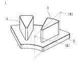
- FIG. 1 is a schematic explanatory view showing an example of a dust core according to an embodiment of the present disclosure.
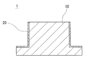
- FIG. 2 is a cross-sectional view taken along line (II)-(II) in FIG.
- FIG. 3 is a diagram for explaining a method of measuring the maximum depth of the unevenness.
- the means for securing the insulation between the powder magnetic core and the coil for example, it is conceivable to coat a resin on the surface of the powder compact to form an insulating resin coating film.
- the insulating resin coating film is formed, it is possible to arrange the coil directly on the dust core, and it is not necessary to increase the current flowing through the coil more than necessary, and the coil current can be reduced.
- reduction of a number of parts and simplification of an assembly operation can be achieved.
- the insulating resin coating film is required to have high electrical insulation properties, and it is desirable that no pinholes or locally thin portions be present.
- a pinhole or a locally thin portion exists in the insulating resin coating film, the portion becomes a starting point of the dielectric breakdown, and the electrical insulation (voltage resistance) is deteriorated.
- Another object of the present invention is to provide an electromagnetic component that can ensure electrical insulation between a dust core and a coil by means of an insulating resin film provided on the dust core.
- the dust core of the present disclosure includes an insulating resin coating film having high electrical insulation.
- the electromagnetic component of the present disclosure can ensure electrical insulation between the dust core and the coil by the insulating resin film provided on the dust core.
- the insulating resin coating film can be formed by applying a resin on the surface of the green compact and then heat treating it to solidify the resin.
- the insulating resin coating film is formed following the surface of the green compact, asperities are also formed on the surface of the insulating resin coating film.
- the unevenness (roughness) of the green compact surface is large, the thickness of the resin may not be uniform when the green compact surface is coated with a resin, and a thin portion of the resin may be formed. For example, the resin may intrude into a portion (valley portion) where the unevenness of the green compact surface is deep, and the resin may become thin at that portion.
- the film thickness of the insulating resin coating film may be extremely thin at a deep portion of the unevenness to form a pinhole.
- the present inventors found that when the insulating resin coating film is formed not on the entire surface of the green compact surface but on a part of the surface and the depth of the unevenness on the insulating resin coating film surface is small, It has been found that there is no pinhole or locally thin portion in the film, and an insulating resin film with high electrical insulation can be obtained.
- embodiments of the present disclosure will be listed and described.
- the dust core according to the present disclosure is A green compact containing soft magnetic powder, And an insulating resin coating film covering a part of the surface of the green compact,
- the ratio of the area of the insulating resin coating film to the surface area of the green compact is 85% or less, and the maximum depth of irregularities on the surface of the insulating resin coating film is 20 ⁇ m or less.
- the powder magnetic core In the powder magnetic core, a part of the surface of the powder compact is covered with an insulating resin coating film.
- the area ratio of the insulating resin coating film to the surface of the green compact is 85% or less.
- the resin in order to form the insulating resin coating film on a part of the surface of the green compact, the resin is coated not on the entire surface of the green compact but on a part thereof. That is, when coating a resin on the powder compact surface to form an insulating resin coating film, there are a coated surface on which the resin is coated and a non-painted surface on which the resin is not coated on the powder compact surface. That is, the entire surface of the green compact is not covered with the resin.
- the insulating resin coating film may be formed on at least a portion of the green compact surface requiring electrical insulation.
- the lower limit of the area ratio of the insulating resin coating film is, for example, 25% or more.
- the possibility that the thin portion of the film thickness is locally formed in the insulating resin coating film is possible because the maximum depth of the unevenness of the insulating resin coating film surface is 20 ⁇ m or less Low. This is because the maximum depth of the unevenness of the insulating resin coating film surface is 20 ⁇ m or less, and the unevenness (roughness) of the green compact surface is small, so when the resin is coated on the green compact surface, the resin is thin. It is because it is hard to form a part.
- the lower limit of the maximum depth of the unevenness of the insulating resin coating film surface is not particularly limited, but is, for example, 1 ⁇ m or more from the viewpoint of the surface properties of the green compact and the like. The measuring method of the largest depth of the unevenness
- the dust core does not have a pinhole or a locally thin portion formed in the insulating resin coating film, and is provided with the insulating resin coating film having high electrical insulation.
- the relative density of the above-mentioned powder compact is 90% or more, and it is mentioned that the maximum depth of unevenness of the above-mentioned powder compact surface is 50 micrometers or less.
- the upper limit of the relative density of the green compact is not particularly limited, but is, for example, 99% or less from the viewpoint of the production conditions of the green compact.
- the "relative density" as used herein means the actual density (the percentage of [measured density of green compact / true density of green compact]) to the true density.
- the true density is the density of the soft magnetic powder contained in the green compact.
- thickness of the above-mentioned insulating resin coat is 25 micrometers or more and 100 micrometers or less.
- the thickness of the insulating resin coating film is 25 ⁇ m or more, the electrical insulation of the insulating resin coating film can be sufficiently secured.
- the thickness of the insulating resin coating film is 100 ⁇ m or less, the insulating resin coating film does not become too thick, and the green compact and the coil can be disposed close to each other when the electromagnetic component is configured. Therefore, it is possible to reduce the current of the coil and to miniaturize the electromagnetic component.
- the electrical insulation (voltage resistance) of the insulating resin coating film is sufficiently high.
- the upper limit of the dielectric breakdown voltage of the insulating resin coating film is not particularly limited, but is, for example, 3000 V or less from the viewpoint of the insulating properties of the resin constituting the insulating resin coating film and the thickness (film thickness) of the coating film. The method of measuring the dielectric breakdown voltage of the insulating resin coating will be described later.
- the insulating resin coating film contains at least one resin of epoxy type, fluorine type and polyimide type.
- the insulating resin coating film is formed by containing a resin having electrical insulation. It is preferable that the resin constituting the insulating resin coating film has high electrical insulation and good adhesion to the green compact. Further, the resin constituting the insulating resin coating film preferably has high heat resistance because the powder magnetic core is in a high temperature state when the electromagnetic component is used. Epoxy-based, fluorine-based and polyimide-based resins are excellent in adhesion and heat resistance in addition to electrical insulating properties, and are suitable as resins constituting an insulating resin coating film.
- the insulating resin coating film is a filler comprising an oxide or a nitride containing at least one element selected from Mg, Si, Al, Mo, Ca, Ti and Zn. Can be mentioned.
- the insulating resin coating film contains the above-described filler, a plurality of fillers are dispersed and present in the insulating resin coating film, and the electrical insulation of the insulating resin coating film can be improved. Specifically, since the pinhole extending in the thickness direction of the insulating resin coating film is divided by the filler, generation of pinholes penetrating in the thickness direction of the coating film from the surface of the insulating resin coating film to the surface of the green compact Can be more effectively prevented.
- the filler made of an oxide or nitride containing at least one element selected from Mg, Si, Al, Mo, Ca, Ti and Zn has high electrical resistance, the insulating property of the resin is Contribute to the improvement of Furthermore, when the insulating resin coating film contains a filler, when the insulating resin coating film is formed on the surface of the corner portion of the green compact (especially when resin is coated), it is not solidified from the corner portion to the flat portion It is easy to control the movement of the resin. Therefore, it can suppress that the insulating resin coating film which covers the corner
- the green compact has a flat portion and a corner portion,
- the thickness of the insulating resin coating film covering the corner portion is 25 ⁇ m or more and 100 ⁇ m or less, It is mentioned that the thickness of the insulating resin coating film covering the flat portion is 0.7 times or more and 1.3 times or less the thickness of the insulating resin coating film covering the corner portion.
- the thickness of the insulating resin coating film covering the corner of the green compact is 25 ⁇ m or more, electrical insulation at the corner can be sufficiently secured.
- the thickness of the insulating resin coating film covering the corner portion is 100 ⁇ m or less, the insulating resin coating film at the corner portion does not become too thick. Therefore, when the electromagnetic component is formed, the green compact and the coil can be disposed close to each other, so that the current of the coil can be reduced, and the electromagnetic component can be miniaturized.
- the thickness of the insulating resin coating film covering the flat portion of the powder compact is 0.7 times or more and 1.3 times or less the thickness of the insulating resin coating film covering the corner portion, so that the electric portion in the flat portion is electrically It is possible to reduce the current of the coil and to miniaturize the electromagnetic component while securing the insulation.
- the above-mentioned powder compact has a phosphate film in the surface.
- the unevenness (roughness) of the green compact surface is reduced. This is because the green compact surface is sealed by phosphating the green compact to form a phosphate film on the surface. Moreover, the effect which improves the adhesiveness of insulating resin coating film can also be anticipated by having a phosphate film.
- the phosphate film include films such as zinc phosphates, iron phosphates, manganese phosphates, and calcium phosphates.
- the electromagnetic component according to the present disclosure is The dust core according to any one of the above (1) to (8), and a coil disposed on the dust core.
- the powder magnetic core according to the present disclosure described above is used as the electromagnetic component, and an insulating resin coating film having high electrical insulation is formed on the surface of the powder magnetic core. Therefore, the said electromagnetic component can ensure the electrical insulation between a dust core and a coil by the insulation resin coating film with which a dust core is equipped.
- an electromagnetic component a motor, a choke coil, a reactor etc. are mentioned, for example.
- FIG. 1 is a schematic perspective view of a dust core 1.
- FIG. 2 shows a cross section cut along line (II)-(II) shown in FIG.
- the powder magnetic core 1 includes a green compact 10 containing soft magnetic powder and an insulating resin coating film 20 covering a part of the surface of the green compact 10.
- One of the characteristics of the powder magnetic core 1 of the embodiment is that the ratio of the area of the insulating resin coating film 20 to the surface area of the green compact 10 is 85% or less, and the maximum depth of the unevenness of the surface of the insulating resin coating film 20 is The point is 20 ⁇ m or less.
- the configuration of the dust core 1 will be described in detail.
- the dust core 1 (powder compact 10) illustrated in FIG. 1 is a component constituting a part of a stator core used in an axial gap type motor, and has a fan-shaped yoke portion 2 and teeth portions protruding from the yoke portion 2. And 3.
- a stator core is configured by assembling the dust cores 1 as a set of six in an annular shape, and a coil (not shown) is wound and disposed on the outer periphery of each tooth portion 3.
- the powder magnetic core 1 a part of the surface of the green compact 10 is covered with the insulating resin coating film 20, and in this example, the outer peripheral surface of the teeth portion 3 in the surface of the green compact 10, and The upper surface of the yoke portion 2 from which the teeth portion 3 protrudes is covered with the insulating resin coating film 20.
- the shape of the dust core 1 can be appropriately selected according to the application and the like, and examples thereof include a cylindrical shape such as a cylindrical shape and a square cylinder shape, and a columnar shape such as a cylinder or a prism.
- the green compact 10 is manufactured, for example, by filling soft magnetic powder in a mold and pressing.
- the green compact 10 contains a soft magnetic powder.
- the soft magnetic powder is a powder made of a soft magnetic material.
- the soft magnetic powder is composed of a plurality of particles.
- As the soft magnetic material for example, pure iron (purity 99 mass% or more), Fe-Si-Al alloy (sendust), Fe-Si alloy (silicon steel), Fe-Al alloy, Fe-Ni system Iron-based alloys such as alloys (permalloy) may be mentioned.
- the soft magnetic powder for example, atomized powder (water atomized powder, gas atomized powder), carbonyl powder, reduced powder and the like can be used.
- the particle surface of the soft magnetic powder may be coated with an insulating film.
- the insulating film intervenes between the particles of the soft magnetic powder constituting the green compact 10, and the electrical insulation between the particles can be enhanced. Therefore, the eddy current loss of the dust core 1 can be reduced.
- the insulating film include a phosphate film, a resin film such as silicone, and an inorganic oxide film such as silica.
- the film thickness of the insulating film is, for example, 20 nm or more and 1 ⁇ m or less.
- Known soft magnetic powders can be used.
- the average particle size of the soft magnetic powder is preferably, for example, 20 ⁇ m or more and 300 ⁇ m or less.
- the average particle diameter of the soft magnetic powder is 20 ⁇ m or more, the oxidation of the soft magnetic powder can be suppressed when pressure-molding. Moreover, the flowability of the powder is good, and the filling property of the powder into the mold can be enhanced.
- the average particle diameter of the soft magnetic powder is 300 ⁇ m or less, the compressibility of the powder is good when pressing and forming, and the green compact 10 can be densified. Further, as the average particle diameter of the soft magnetic powder is smaller, the unevenness (roughness) of the surface of the green compact 10 tends to be smaller.
- the average particle size of the soft magnetic powder is obtained by observing the cross section of the green compact 10 with a microscope such as a scanning electron microscope (SEM), and the circle equivalent diameter equal to the cross sectional area of each particle for all particles of the soft magnetic powder in the field of view. It can obtain
- the visual field size is set so that 100 or more particles are observed in one visual field, and the average value of the cross-sectional equivalent circle diameters of the particles measured by observing 10 different visual fields is an average of the soft magnetic powder.
- the particle size be.
- the visual field size may be 1.0 to 4.5 mm 2 and the magnification may be 50 to 100 times.
- the average particle size of the soft magnetic powder is about the same before and after pressing.
- the average particle size of the soft magnetic powder is, for example, more preferably 40 ⁇ m or more and 250 ⁇ m or less.
- the unevenness (roughness) of the surface of the powder compact 10 be small.
- the maximum depth of the unevenness on the surface of the powder compact 10 is preferably 50 ⁇ m or less, and more preferably 35 ⁇ m or less.
- the maximum depth of the unevenness on the surface of the powder compact 10 is 50 ⁇ m or less, the depth of the unevenness on the surface of the insulating resin coating 20 is sufficiently small.
- the maximum depth of the unevenness on the surface of the insulating resin coating 20 is 20 ⁇ m or less Can be realized.
- the lower limit of the maximum depth of the unevenness of the surface of the powder compact 10 is not particularly limited, but is, for example, 5 ⁇ m or more from the viewpoint of the manufacturing conditions of the powder compact 10 and the like.
- the maximum depth of the irregularities on the surface of the green compact 10 is, for example, preferably 30 ⁇ m or less, and more preferably 25 ⁇ m or less.
- the maximum depth of the unevenness of the powder compact surface can be determined as the maximum value of the height of the roughness curvilinear element of the powder compact 10 surface.
- the "roughness curve element” is a curve portion consisting of a pair of adjacent peaks and valleys in the roughness curve, and the “peak” is a portion above the X axis (average line) of the roughness curve.
- “Valley” refers to a portion below the X axis (mean line) of the roughness curve.
- Height of roughness curvilinear element is expressed by the sum of peak height and valley depth in one roughness curvilinear element, "peak height” is the height from the X axis to the summit, and “valley depth” is X The depth from the shaft to the bottom of the valley. A method of measuring the maximum depth of unevenness of the surface of the green compact 10 will be described with reference to FIG. As shown in FIG.
- the surface roughness of the powder compact 10 is obtained by measuring the surface of the powder compact 10 with a surface roughness measuring instrument and observing the cross section of the powder compact 10 by SEM etc. May be extracted and acquired.
- the surface roughness measuring device may be a known one such as a contact type using a stylus or a non-contact type using a laser beam.
- the relative density of the green compact 10 is preferably 90% or more.
- the relative density of the powder compact 10 is 90% or more, the unevenness (roughness) on the surface of the powder compact 10 becomes sufficiently small, and when the resin is coated on the surface of the powder compact 10, a thin portion of the resin is formed. It is difficult to form a thin portion locally on the insulating resin coating film 20 effectively.
- the relative density of the green compact 10 can be obtained by dividing the measured density of the green compact 10 by the true density. In the present embodiment, the density of the soft magnetic material constituting the soft magnetic powder is taken as the true density.
- the upper limit of the relative density of the green compact 10 is not particularly limited, but is, for example, 99% or less from the viewpoint of the production conditions of the green compact 10 and the like.
- the relative density of the green compact 10 is, for example, 92% or more, more preferably 94% or more.
- the green compact 10 can be densified, and the relative density of the green compact 10 becomes higher, as the molding pressure at the time of pressure molding the soft magnetic powder becomes higher.
- the molding pressure may be, for example, 600 MPa or more and 1,500 MPa or less.
- the mold may be heated and pressure molding may be performed warmly. In the case of warm pressure molding, the molding temperature (mold temperature) may be, for example, 60 ° C. or more and 200 ° C. or less.
- a lubricant may be added to the soft magnetic powder for the purpose of reducing the friction between the soft magnetic powder, the mold, and the particles of the soft magnetic powder.
- solid lubricants such as fatty acid amide and metal soap can be used.
- fatty acid amides include fatty acid amides such as stearic acid amide and ethylenebisstearic acid amide
- metal soaps include metal stearates such as zinc stearate and lithium stearate.
- the green compact 10 may be heat-treated for the purpose of removing the strain introduced during the pressure forming. Thereby, the magnetic characteristics of the dust core 1 can be improved.
- the heating temperature may be, for example, 300 ° C. or more and 900 ° C. or less.
- the green compact 10 may have a phosphate coating (not shown) on its surface.
- a phosphate coating (not shown) on its surface.
- the surface of the powder compact 10 is sealed, and the unevenness (roughness) of the surface of the powder compact 10 is reduced.
- the effect which improves the adhesiveness of the insulation resin coating film 20 can also be anticipated by having a phosphate film.
- the phosphate film include films such as zinc phosphates, iron phosphates, manganese phosphates, and calcium phosphates.
- a phosphate film can be formed by phosphating the green compact 10 using a solution of phosphate.
- the phosphate treatment is, specifically, applying a phosphate solution to the surface of the green compact 10 by spraying, immersing the green compact 10 in a phosphate solution, and the like.
- the phosphate treatment chemically forms a phosphate film on the surface of the green compact 10.
- the film thickness of the phosphate film is not particularly limited, but when the film is too thin, a sufficient effect can not be obtained, and when the film is too thick, the processing time is long.
- the film thickness of the phosphate film is, for example, 1 ⁇ m to 10 ⁇ m, Furthermore, it is preferable that they are 2 micrometers or more and 7 micrometers or less.
- the film thickness of a phosphate film can be calculated
- the film thickness of 10 points per one visual field is measured, and the average value of the film thickness measured by observing 10 different visual fields is set as the film thickness of the phosphate film.
- the magnification of the SEM may be 1000 times (7000 ⁇ m 2 / field of view).
- the insulating resin coating film 20 is formed by applying a resin having electrical insulation to a part of the surface of the green compact 10 (in this example, the outer peripheral surface of the teeth 3 and the upper surface of the yoke 2). It covers part of the surface of the powder 10.
- the insulating resin coating film 20 may be formed on at least a portion of the surface of the green compact 10 requiring electrical insulation. For example, when a coil is disposed on the dust core 1 to configure an electromagnetic component, the coil Provided on the surface in contact with the
- the insulating resin coating film 20 is formed by containing a resin having electrical insulation.
- the insulating resin coating film 20 preferably contains, for example, at least one resin of an epoxy resin, a fluorine resin, and a polyimide resin. It is preferable that the resin constituting the insulating resin coating film 20 has high electrical insulation and good adhesion to the green compact. Moreover, since the powder magnetic core will be in a high temperature state at the time of use of electromagnetic components, it is preferable that the resin which comprises the insulation resin coating film 20 has high heat resistance. Epoxy-based, fluorine-based and polyimide-based resins are excellent in adhesion and heat resistance in addition to electrical insulating properties, and thus are suitable as the resin constituting the insulating resin coating film 20.
- the resin constituting the insulating resin coating film 20 may contain a filler described later.
- the insulating resin coating film 20 can be formed by heat treatment to solidify the resin.
- a method of coating the resin for example, applying a resin solution in which a resin is dissolved in a solvent onto the surface of the green compact 10 by spraying, or immersing the green compact 10 in the resin solution may be mentioned.
- resin coating can also be performed by electrodeposition coating or powder coating.
- a resin is applied to a part of the surface of the green compact 10.
- the non-painted surface on which the resin is not coated in this example, the upper end surface of the teeth portion 3 and the circumferential surface of the yoke portion 2 and It is preferable to mask the lower surface.
- a masking tape such as Kapton (registered trademark) tape may be attached to an unpainted surface.
- the masking tape is peeled off before heat treatment after coating, and the non-painted surface is exposed during heat treatment.
- the heat processing temperature which solidifies resin is based also on the kind of resin, setting it as 40 degreeC or more and 150 degrees C or less is mentioned, for example.
- the ratio of the area of the insulating resin coating film 20 to the surface area of the green compact 10 is 85% or less.
- the resin coating film 20 is formed on a part of the surface of the green compact 10
- the resin There is a painted surface on which to paint and a non-painted surface on which the resin is not painted.
- This non-painted surface functions as an escape route for air in pores inside the green compact 10 during heat treatment after painting, so that thermally expanded air is prevented from breaking through the resin on the painted surface and escaped from the pinhole. Prevent occurrence.
- the lower limit of the area ratio of the insulating resin coating film 20 is determined by the area of the portion (for example, the contact surface with the coil) of the green compact 10 (dust magnetic core 1) requiring at least electrical insulation, and is, for example, 25% or more .
- the area ratio of the insulating resin coating film 20 can be determined by dividing the area of the insulating resin coating film 20 (the area of the coated surface of the green compact 10) by the surface area of the green compact 10.
- the maximum depth of the unevenness on the surface of the insulating resin coating film 20 is 20 ⁇ m or less. Since the insulating resin coating film 20 is formed following the surface of the green compact 10, the surface property of the insulating resin coating film 20 depends on the surface quality of the green compact 10. For example, the smaller the maximum depth of the unevenness on the surface of the green compact 10 described above, the smaller the maximum depth of the unevenness on the surface of the insulating resin coating film 20 tends to be. When the maximum depth of the unevenness on the surface of the insulating resin coating film 20 is 20 ⁇ m or less, there is a low possibility that the insulating resin coating film 20 locally has a thin portion.
- the maximum depth of the unevenness on the surface of the insulating resin coating film 20 is 20 ⁇ m or less, the maximum depth of the unevenness on the surface of the powder compact 10 is small. Therefore, when the resin is coated on the surface of the green compact 10, it is difficult to form a thin portion of the resin. In addition, since the thickness of the resin is prevented from becoming extremely thin, pinholes are not formed.
- the lower limit of the maximum depth of the unevenness on the surface of the insulating resin coating film 20 is not particularly limited, but is, for example, 1 ⁇ m or more from the viewpoint of the surface properties of the green compact 10 and the like.
- the maximum depth of the irregularities on the surface of the insulating resin coating film 20 is, for example, preferably 15 ⁇ m or less, and more preferably 10 ⁇ m or less.
- the maximum depth of the unevenness on the surface of the insulating resin coating film 20 can be determined as the maximum value of the height of the roughness curvilinear element on the surface of the insulating resin coating film 20.
- the maximum depth of the unevenness on the surface of the insulating resin coating film 20 can be measured in the same manner as the method for measuring the maximum depth of the unevenness on the surface of the powder compact 10 described above. Specifically, as shown in FIG.
- the roughness curve of the surface of the insulating resin coating film 20 is acquired, and only the reference length L is extracted from the roughness curve in the direction of the average line, and the average line of the extracted portion is
- the maximum depth of the unevenness of the surface of the insulating resin coating film 20 is measured according to JIS B601: 2001 using a surface roughness measuring machine (SURFCOM1400D-3DF) manufactured by Tokyo Seimitsu Co., Ltd.
- the maximum height Rz value of the roughness curve is taken as the maximum depth of the unevenness as a reference length of 0.8 mm and a measurement length of 4.0 mm (five times the reference length) in the roughness curve.
- the measurement length is required to be 2.0 mm or more.
- the thickness of the insulating resin coating film 20 is preferably 25 ⁇ m or more and 100 ⁇ m or less. As the film thickness of the insulating resin coating film 20 is thicker, it is more difficult to locally form a thin film portion. While the electrical insulation (voltage resistance) of the insulating resin coating film 20 becomes high, there is a tendency for the maximum depth of irregularities on the surface of the insulating resin coating film 20 to be small. When the thickness of the insulating resin coating film 20 is 25 ⁇ m or more, the electrical insulation of the insulating resin coating film 20 can be sufficiently ensured.
- the thickness of the insulating resin coating film 20 is 100 ⁇ m or less, the insulating resin coating film 20 does not become too thick, and when the powder magnetic core 1 is used to construct an electromagnetic component, coil current reduction, electromagnetic component Can be miniaturized.
- the thickness of the insulating resin coating film 20 is, for example, preferably 30 ⁇ m or more, and more preferably 45 ⁇ m or more.
- the thickness of the insulating resin coating film 20 can be obtained by observing the cross section orthogonal to the surface of the insulating resin coating film 20 with an optical microscope or the like to measure the film thickness and calculating the average value of the film thickness measurement values. it can.
- the film thickness of 10 points per field of view is measured, and the average value of the film thickness measured by observing 10 different fields of view is taken as the thickness of the insulating resin coating film 20.
- the magnification of the optical microscope may be 450 times (0.14 mm 2 / field of view).
- the thickness of the insulating resin coating film (hereinafter sometimes referred to as “corner portion coating film”) covering the corner portions of the powder compact 10 is an electrical insulating property.
- the thicker the better in terms of securing the The thickness of the corner portion coating is preferably 25 ⁇ m or more, and more preferably 40 ⁇ m or more.
- the insulating resin coating film (hereinafter referred to as a "flat surface coating film”) covers the flat portion except the corners of the green compact 10. Some) tend to be thicker than the corner coating.
- the insulating resin coating film 20 having a sufficient thickness is formed from the flat portion of the green compact 10 to the corner portion. That is, regardless of the presence or absence of the corners of the green compact 10, the thickness of the insulating resin coating film 20 formed on the surface of the green compact 10 is preferably 25 ⁇ m or more. Sufficient electrical insulation between the coils can be ensured.
- the upper limit of the thickness of the corner portion coating is preferably, for example, about 100 ⁇ m.
- the thickness of the flat portion coating film may be, for example, about 0.7 times to 1.3 times the thickness of the corner portion coating film.
- corner refers to a ridgeline portion formed by the intersection of two adjacent flat portions.
- the thickness of the coating of the corner portion is, for example, when the corner portion of the green compact 10 is R-chamfered, the insulating resin in the normal direction to the curved ridge line formed by R-chamfering in the cross section of the powder magnetic core 1
- the thickness of the coating film 20 is indicated.
- the thickness of the insulating resin coating film 20 in the direction orthogonal to the linear ridge line formed by the C-chamfering is indicated.
- the average value of the thickness of the insulating resin coating film 20 in a plurality of normal directions may be taken as the thickness of the corner coating film.
- the thickness of the insulating resin coating film 20 in the direction that bisects between the extension faces of each of the two flat portions forming the corner is the thickness of the corner coating film Do.
- the thickness of the corner portion coating can be measured, for example, by observing the cross section of the dust core 1 with an optical microscope or the like. C-chamfering is obtained by removing the corner that is the end and making it a flat surface.
- R-chamfering is obtained by removing a corner that is an end portion and forming a curved surface.
- the specific method of C chamfering and R chamfering is not limited to the case of directly removing the corner of the end, and is formed using a mold or the like in which a portion corresponding to the chamfer is formed. It is also good.
- the insulating resin coating film 20 may contain an insulating filler. Thereby, a plurality of fillers are dispersed and present in the insulating resin coating film 20, and the electrical insulation of the insulating resin coating film 20 can be improved. Specifically, the pinhole extending in the thickness direction of the insulating resin coating film 20 is divided by the filler, and the generation of pinholes penetrating in the thickness direction from the surface of the insulating resin coating film 20 to the surface of the powder compact 10 is more effective. Can be prevented. Moreover, when forming the insulating resin coating film 20 on the surface of the corner of the green compact 10, the resin contains a filler, thereby suppressing the movement of the unsolidified resin from the corner to the plane during coating of the resin. Easy to do. Therefore, it can suppress that a corner coating film becomes thin locally, and can improve the ratio of the thickness of the corner coating film with respect to the thickness of a plane part coating film.
- Ceramics with high electrical resistance are mentioned.
- oxides or nitrides containing at least one element selected from Mg, Si, Al, Mo, Ca, Ti and Zn can be mentioned. More specifically, magnesium silicate, silica, alumina, titanium oxide, aluminum nitride and the like can be mentioned.
- the shape of the filler is not particularly limited.
- the filler may be flaky or particulate.
- the thickness is 0.1 ⁇ m to 5 ⁇ m
- the width is 5 ⁇ m to 30 ⁇ m
- the length is 5 ⁇ m to 30 ⁇ m.
- the average particle size is preferably 0.1 ⁇ m to 10 ⁇ m.
- the thickness of the flaky filler is 0.1 ⁇ m or more and the width and length is 5 ⁇ m or more, or the average particle diameter of the particulate filler is 0.1 ⁇ m or more, the pinhole is easily divided, and the insulating resin coating film The effect of improving the electrical insulation of 20 is easily obtained.
- the thickness of the flaky filler is 5 ⁇ m or less and the width and length are 30 ⁇ m or less, or the average particle diameter of the particulate filler is 10 ⁇ m or less, the size of the filler is not too large. It is easy to disperse the filler uniformly.
- the thickness of the insulating resin coating film 20 can be made as thin as possible, and the insulating resin coating film 20 can be made excellent in electrical insulation.
- content of a filler is based also on the material of a filler, a shape, etc.
- the insulation resin coating film 20 shall be 100 mass%, it is preferable that they are 30 mass% or more and 70 mass% or less.
- the filler in the insulating resin coating film 20 is 30% by mass or more, the filler is sufficiently present in the insulating resin coating film 20, and the electrical insulating property of the insulating resin coating film 20 is sufficiently improved.
- the content of the filler is 70% by mass or less, when the insulating resin coating film 20 is formed, the flowability at the time of coating of the resin can be easily secured. Therefore, the thickness of the insulating resin coating film 20 can be uniform as a whole, and the insulating resin coating film 20 can be excellent in electrical insulation.
- the dielectric breakdown voltage of the insulating resin coating film 20 is preferably greater than 600V. When the dielectric breakdown voltage of the insulating resin coating film 20 exceeds 600 V, the electrical insulation (voltage resistance) of the insulating resin coating film 20 is sufficiently high.
- the upper limit of the dielectric breakdown voltage of the insulating resin coating film 20 is not particularly limited, but is, for example, 3000 V or less from the viewpoint of the insulating properties of the resin constituting the insulating resin coating film 20 and the thickness (film thickness) of the coating film.
- the dielectric breakdown voltage of the insulating resin coating film 20 is, for example, 700 V or more, more preferably 1000 V or more, although it depends on the use conditions of the dust core 1 and the like.
- the dielectric breakdown voltage of the insulating resin coating film 20 is measured as follows.
- the electrode is attached to the surface of the insulating resin coating film 20, and the electrode is attached to the surface of the green compact 10 not covered with the insulating resin coating film 20 (non-painted surface of the green compact 10 surface).
- the detection current flowing between both electrodes is fixed.
- the voltage to be applied is raised stepwise, and the voltage value when the detection current becomes 1 mA or more is taken as the dielectric breakdown voltage.
- a part of the surface of the green compact 10 is covered with the insulating resin coating film 20.
- the area ratio of the insulating resin coating film 20 to the surface of the green compact 10 is 85% or less. Therefore, when coating the resin on the surface of the green compact 10 to form the insulating resin coating film 20, the resin is coated not on the entire surface of the green compact 10 but on a part thereof. Is not covered with resin. Therefore, even if the air in the pores inside the green compact 10 thermally expands during the heat treatment after coating, the air can be released from the non-painted surface of the green compact 10 surface. Since it is possible to prevent thermally expanded air from breaking through the resin on the painted surface and escaping, the occurrence of pinholes can be prevented. When the area ratio of the insulating resin coating film 20 is 85% or less, the area of the non-painted surface which functions as a relief for air can be sufficiently secured. Therefore, the occurrence of pinholes in the insulating resin coating film 20 can be effectively prevented.
- the maximum depth of the unevenness on the surface of the insulating resin coating film 20 is 20 ⁇ m or less, there is a low possibility that a portion having a small film thickness is locally formed on the insulating resin coating film 20. Therefore, there is no pinhole or a locally thin portion in the insulating resin coating film 20. Therefore, the dust core 1 is provided with the insulating resin coating film 20 having high electrical insulation.
- the dust core 1 of the embodiment described above can be used for the core of an electromagnetic component (motor in the example shown in FIG. 1). Since the powder magnetic core 1 is provided with the insulating resin coating film 20 having high electrical insulation, when the coil is disposed to constitute an electromagnetic component, electrical insulation between the coil and the coil can be secured.
- the electromagnetic component according to the embodiment includes the dust core 1 of the above-described embodiment and a coil disposed in the dust core 1.
- a coil (not shown) is disposed on the outer periphery of the teeth portion 3 of the dust core 1 provided with the insulating resin coating film 20.
- the electromagnetic component of the embodiment described above can ensure electrical insulation between the dust core 1 and the coil by the insulating resin coating film 20 provided on the dust core 1.
- the average particle size (D50) at this time means a particle size at which the integrated mass becomes 50% as measured using a laser diffraction / scattering type particle size / particle size distribution measuring apparatus.
- the prepared soft magnetic powder is manufactured by a water atomization method.
- a phosphate film was coated on the particle surface of the soft magnetic powder to form an insulating film. The film thickness of the insulating film was about 100 nm.
- the prepared soft magnetic powder was filled in a mold and pressure-formed to prepare a plurality of cylindrical green compacts having an inner diameter of 20 mm, an outer diameter of 30 mm, and a height of 20 mm.
- the green compact was heat treated at 500 ° C. for 15 minutes in a nitrogen atmosphere.
- various green compacts having different relative densities were obtained by changing the molding pressure at the time of pressure molding.
- the green compact was dipped in a manganese phosphate solution and treated with manganese phosphate to form a manganese phosphate-based phosphate film on the surface layer of the green compact.
- the film thickness of the phosphate film was about 3 ⁇ m.
- the weight and volume of the green compact were measured to calculate the actual density, and the relative density was determined from the actual density and the true density (density of the pure iron powder with an insulating film).
- corrugation of each green compact surface was evaluated.
- the maximum depth of the unevenness on the surface of the green compact was obtained by measuring the surface roughness of the inner peripheral surface of the green compact and obtaining the maximum value of the height of the roughness curvilinear element from the obtained roughness curve.
- the reference length of the roughness curve was 4 mm, and the evaluation length of the roughness curve was 5 times the reference length.
- epoxy resin, fluorine resin and polyimide (PI) resin were prepared respectively.
- various resins were coated on the surface of the produced green compact, and then heat treated to cure the resin, thereby forming an insulating resin coating film.
- the epoxy resin and the fluorine resin were dissolved in a solvent and applied to the surface of the green compact by spraying.
- the polyimide resin was electrodeposited on the surface of the green compact.
- the area ratio of the coated surface to the green compact surface and the coating amount per unit area are changed, so that the area of the insulating resin coating film
- the ratio and the film thickness of the insulating resin coating film were made different. Specifically, samples of various dust cores as shown in Table 1 were produced.
- a resin was applied to a part of the green compact surface, a masking tape was attached to the unpainted surface of the green compact surface for masking.
- the surface of the insulating resin coating was observed by SEM to evaluate the presence or absence of pinholes in the insulating resin coating. If there is a pinhole with a diameter of 100 ⁇ m or more in a 1 cm square field of view, check if there is a pinhole with a diameter of 100 ⁇ m or more. "No pinhole". As a result, the sample (No. 12, 16, 17) of which the area ratio of the insulating resin coating film is 100% and the sample (No. 13) of 90.0% were "with pinholes". Moreover, even if the area ratio of the insulating resin coating film is 85% or less, the samples (Nos.
- the film thickness of the insulating resin coating film was measured for each of the powder magnetic core samples on which the insulating resin coating film was formed, and the average thickness was determined. Moreover, the maximum depth of the unevenness
- the maximum depth of the unevenness of the insulating resin coating film surface is a roughness curve element from the acquired roughness curve
- the maximum value of the height of the The reference length of the roughness curve was 4 mm, and the evaluation length of the roughness curve was 5 times the reference length. In the case of samples (Nos.
- the surface roughness of the portion without pinholes on the insulating resin coating film surface is measured to determine the unevenness of the insulating resin coating film surface. I asked for the maximum depth of
- Table 1 shows the area ratio of the insulating resin coating film, the thickness of the insulating resin coating film, and the maximum depth of the unevenness of the insulating resin coating film surface in each sample of the powder magnetic core shown in Table 1.
- the dielectric breakdown voltage was measured for each sample of the dust core shown in Table 1 to evaluate the electrical insulation (voltage resistance).
- the measurement of the breakdown voltage was performed as follows. An electrode is attached to the surface of the insulating resin coating film formed on the inner circumferential surface of the green compact. The electrode is attached to the outer surface of the green compact not covered with the insulating resin coating. A constant voltage is applied between both electrodes for 1 minute. Then, the voltage applied between both electrodes is raised stepwise by 100V. Measure the voltage value (withstand voltage) when the detection current flowing between both electrodes becomes 1 mA or more. The results are shown in Table 1.
- sample No. 1 in which the area ratio of the insulating resin coating film is 85% or less and the maximum depth of irregularities of the insulating resin coating film surface is 20 ⁇ m or less. 1 to 10 had high electrical insulation (voltage resistance) in which the dielectric breakdown voltage of the insulating resin coating film exceeded 600 V. The reason for this is considered that in these samples, pinholes and locally thin portions do not exist in the insulating resin coating film, and an insulating resin coating film having high electrical insulation property is obtained.
- a sample having a maximum depth of unevenness of 15 ⁇ m or less on the surface of the insulating resin coating film has a dielectric breakdown voltage of 1000 V or more, so the insulating resin coating film has higher electrical insulation.
- a sample having a maximum depth of 10 ⁇ m or less on the surface of the insulating resin coating film surface has a dielectric breakdown voltage of 2000 V or more. From this, as the maximum depth of the unevenness on the surface of the insulating resin coating film is smaller, the possibility that the thin portion of the film thickness is locally formed in the insulating resin coating film is low, and the electrical insulation property is improved. Conceivable.
- the surface properties of the green compact are important, and the relative density of the green compact is high (90% or more), and the unevenness of the green compact surface It can be seen that it is desirable that the maximum depth of is small (50 .mu.m or less, particularly 35 .mu.m or less).
- the dielectric breakdown voltage of the insulating resin coating film was 600 V or less, and it did not have sufficient electrical insulation. This is considered to be due to the fact that, in the sample in which the area ratio of the insulating resin coating film is over 85%, the pinholes are present in the insulating resin coating film, so that the electrical insulation property is lowered.
Abstract
A powder magnetic core comprises: a powder compact containing a soft magnetic powder; and an insulating resin coating film that covers a portion of the surface of the powder compact, wherein the ratio of the area of the insulating resin coating film with respect to the surface area of the powder compact is 85% or less, and the maximum depth of the recesses and projections of the insulating resin coating film surface is 20 µm or less.
Description
本開示は、圧粉磁心、及び電磁部品に関する。本出願は2017年8月10日出願の日本特許出願第2017-156041号に基づく優先権を主張し、前記日本特許出願に記載された全ての内容を援用するものである。
The present disclosure relates to a dust core and an electromagnetic component. This application claims the priority based on Japanese Patent Application No. 2017-156041 filed on Aug. 10, 2017, and incorporates all the contents described in the Japanese Patent Application.
従来、磁心(コア)にコイルを配置したモータやチョークコイル、リアクトルなどの電磁部品が知られている。近年、電磁部品の磁心として圧粉磁心が使用されている。一般に、圧粉磁心は、軟磁性粉末を加圧成形した圧粉体で構成されている。
DESCRIPTION OF RELATED ART Conventionally, electromagnetic components, such as a motor which arrange | positions a coil in a magnetic core (core), a choke coil, a reactor, etc., are known. In recent years, a powder magnetic core has been used as a magnetic core of an electromagnetic component. In general, a dust core is constituted by a green compact obtained by pressure molding soft magnetic powder.
特許文献1には、軟磁性粉末の粒子表面に絶縁被覆を有する被覆軟磁性粉末を加圧成形した成形体(圧粉体)と、成形体の表面全域を覆う防錆層とを備える圧粉磁心が開示されている。
Patent Document 1 discloses a green compact comprising a compact (green compact) obtained by pressure molding a coated soft magnetic powder having an insulating coating on the particle surface of the soft magnetic powder, and an anticorrosive layer covering the entire surface of the compact. A magnetic core is disclosed.
本開示に係る圧粉磁心は、
軟磁性粉末を含有する圧粉体と、
前記圧粉体の表面の一部を覆う絶縁樹脂塗膜とを備え、
前記圧粉体の表面積に対する前記絶縁樹脂塗膜の面積の割合が85%以下、かつ、前記絶縁樹脂塗膜表面の凹凸の最大深さが20μm以下である。 The dust core according to the present disclosure is
A green compact containing soft magnetic powder,
And an insulating resin coating film covering a part of the surface of the green compact,
The ratio of the area of the insulating resin coating film to the surface area of the green compact is 85% or less, and the maximum depth of irregularities on the surface of the insulating resin coating film is 20 μm or less.
本開示に係る電磁部品は、
本開示に係る圧粉磁心と、前記圧粉磁心に配置されるコイルとを備える。 The electromagnetic component according to the present disclosure is
The dust core according to the present disclosure, and a coil disposed on the dust core.
本開示に係る圧粉磁心と、前記圧粉磁心に配置されるコイルとを備える。 The electromagnetic component according to the present disclosure is
The dust core according to the present disclosure, and a coil disposed on the dust core.
[本開示が解決しようとする課題]
電磁部品において、圧粉磁心とコイルとの間の電気的絶縁を確保する目的で、従来より圧粉磁心とコイルとの間に絶縁紙を挟んだり、樹脂製のボビンを介在させて配置したりすることが行われている。しかしながら、絶縁紙やボビンを使用して絶縁を確保する構成では、圧粉磁心とコイルとの間隔が大きくなって必要以上に大きな電流をコイルに流す必要が生じたり、組立作業の煩雑化を招いたりする場合がある。 [Problems to be solved by the present disclosure]
In the electromagnetic components, in order to ensure electrical insulation between the dust core and the coil, conventionally, an insulating paper is sandwiched between the dust core and the coil, or a resin bobbin is interposed between the dust core and the coil. It is done. However, in the configuration in which insulation is secured using insulating paper or a bobbin, the distance between the dust core and the coil becomes large, and it becomes necessary to flow a current larger than necessary to the coil, or the assembly operation becomes complicated. There are times when
圧粉磁心とコイルとの間の絶縁を確保する手段の1つとして、例えば、圧粉体の表面に樹脂を塗装して絶縁樹脂塗膜を形成することが考えられる。絶縁樹脂塗膜を形成した場合、圧粉磁心にコイルを直接配置することが可能であり、コイルに流す電流を必要以上に大きくする必要がなく、コイルの低電流化が図れる。更には、絶縁紙やボビンを使用する場合に比べて電磁部品を小型化できると共に、部品点数の削減、組立作業の簡素化を図ることができる。
As one of the means for securing the insulation between the powder magnetic core and the coil, for example, it is conceivable to coat a resin on the surface of the powder compact to form an insulating resin coating film. When the insulating resin coating film is formed, it is possible to arrange the coil directly on the dust core, and it is not necessary to increase the current flowing through the coil more than necessary, and the coil current can be reduced. Furthermore, compared with the case where insulating paper and a bobbin are used, while being able to miniaturize an electromagnetic component, reduction of a number of parts and simplification of an assembly operation can be achieved.
絶縁樹脂塗膜には、高い電気絶縁性が求められ、ピンホールや局所的に膜厚の薄い部分が存在しないことが望まれる。絶縁樹脂塗膜にピンホールや局所的に薄い部分が一箇所でも存在すると、その部分が絶縁破壊の起点になることから、電気絶縁性(耐電圧性)が劣化する。
The insulating resin coating film is required to have high electrical insulation properties, and it is desirable that no pinholes or locally thin portions be present. When a pinhole or a locally thin portion exists in the insulating resin coating film, the portion becomes a starting point of the dielectric breakdown, and the electrical insulation (voltage resistance) is deteriorated.
そこで、本開示は、電気絶縁性の高い絶縁樹脂塗膜を備える圧粉磁心を提供することを目的の一つとする。また、圧粉磁心に備える絶縁樹脂被膜によって圧粉磁心とコイルとの間の電気的絶縁を確保できる電磁部品を提供することを別の目的の一つとする。
[本開示の効果] Then, this indication makes it an object to provide a dust core provided with insulating resin coat with high electric insulation. Another object of the present invention is to provide an electromagnetic component that can ensure electrical insulation between a dust core and a coil by means of an insulating resin film provided on the dust core.
[Effect of the present disclosure]
本開示の圧粉磁心は、電気絶縁性の高い絶縁樹脂塗膜を備える。本開示の電磁部品は、圧粉磁心に備える絶縁樹脂被膜によって圧粉磁心とコイルとの間の電気的絶縁を確保できる。
The dust core of the present disclosure includes an insulating resin coating film having high electrical insulation. The electromagnetic component of the present disclosure can ensure electrical insulation between the dust core and the coil by the insulating resin film provided on the dust core.
[本開示の実施形態の説明]
本発明者らは、圧粉体の表面に電気絶縁性の高い絶縁樹脂塗膜を形成する方法について鋭意研究した結果、以下の知見を得た。 [Description of the embodiment of the present disclosure]
The present inventors earnestly studied the method of forming an insulating resin coating film with high electrical insulation on the surface of a green compact, and obtained the following findings.
圧粉体は、粉末を押し固めたものであるため、多数の気孔が存在し、表面に凹凸を有する。絶縁樹脂塗膜は、圧粉体の表面に樹脂を塗装した後、熱処理して樹脂を固化させることで形成できる。
Since the green compact is a compacted powder, a large number of pores are present, and the surface has irregularities. The insulating resin coating film can be formed by applying a resin on the surface of the green compact and then heat treating it to solidify the resin.
圧粉体表面に樹脂を塗装して絶縁樹脂塗膜を形成する際、塗装後の熱処理時に圧粉体内部の気孔内の空気が熱膨張して外に逃げようとする。圧粉体表面の全面に樹脂を塗装した場合は、圧粉体の表面全体が樹脂で覆われることになるため、空気の逃げ道がなく、外に逃げようとする空気が樹脂を突き破ることによって、絶縁樹脂塗膜にピンホールが発生することがある。特に、ピンホールの直径が100μm以上の場合、電気絶縁性に与える影響が大きい。
When a resin is coated on the surface of the green compact to form an insulating resin coating film, the air in the pores inside the green compact is thermally expanded and escapes to the outside during heat treatment after coating. When the entire surface of the powder compact is coated with resin, the entire surface of the powder compact is covered with the resin, so there is no way for air to escape, and the air trying to escape to the outside breaks through the resin, Pin holes may occur in the insulating resin coating. In particular, when the diameter of the pinhole is 100 μm or more, the influence on the electrical insulation is large.
また、絶縁樹脂塗膜は、圧粉体の表面に倣って形成されるので、絶縁樹脂塗膜の表面にも凹凸が形成される。圧粉体の表面の凹凸が大きく、粗さが大きいほど、絶縁樹脂塗膜の表面の凹凸も大きくなる。つまり、表面粗さも大きくなる傾向がある。圧粉体表面の凹凸(粗さ)が大きい場合は、圧粉体表面に樹脂を塗装した際に樹脂の厚さが均一にならず、樹脂の薄い部分が形成されることがある。例えば、圧粉体表面の凹凸が深い部分(谷の部分)に樹脂が入り込み、その箇所で樹脂が薄くなることがある。この場合、絶縁樹脂塗膜表面に凹凸の深い部分が存在しており、絶縁樹脂塗膜に局所的に膜厚の薄い部分が形成される可能性が高い。場合によっては、凹凸の深い部分で絶縁樹脂塗膜の膜厚が極端に薄くなり過ぎて、ピンホールが形成される場合もあり得る。
In addition, since the insulating resin coating film is formed following the surface of the green compact, asperities are also formed on the surface of the insulating resin coating film. The larger the unevenness of the surface of the powder compact and the larger the roughness, the larger the unevenness of the surface of the insulating resin coating film. That is, the surface roughness also tends to increase. When the unevenness (roughness) of the green compact surface is large, the thickness of the resin may not be uniform when the green compact surface is coated with a resin, and a thin portion of the resin may be formed. For example, the resin may intrude into a portion (valley portion) where the unevenness of the green compact surface is deep, and the resin may become thin at that portion. In this case, there is a deep uneven portion on the surface of the insulating resin coating film, and there is a high possibility that the thin portion of the film thickness is locally formed on the insulating resin coating film. In some cases, the film thickness of the insulating resin coating film may be extremely thin at a deep portion of the unevenness to form a pinhole.
本発明者らは、以上の知見から、圧粉体表面の全面ではなく一部に絶縁樹脂塗膜が形成され、かつ、絶縁樹脂塗膜表面の凹凸の深さが小さい場合に、絶縁樹脂塗膜にピンホールや局所的に薄い部分が存在せず、電気絶縁性の高い絶縁樹脂塗膜が得られることを見出した。最初に、本開示の実施態様を列記して説明する。
From the above findings, the present inventors found that when the insulating resin coating film is formed not on the entire surface of the green compact surface but on a part of the surface and the depth of the unevenness on the insulating resin coating film surface is small, It has been found that there is no pinhole or locally thin portion in the film, and an insulating resin film with high electrical insulation can be obtained. First, embodiments of the present disclosure will be listed and described.
(1)本開示に係る圧粉磁心は、
軟磁性粉末を含有する圧粉体と、
前記圧粉体の表面の一部を覆う絶縁樹脂塗膜とを備え、
前記圧粉体の表面積に対する前記絶縁樹脂塗膜の面積の割合が85%以下、かつ、前記絶縁樹脂塗膜表面の凹凸の最大深さが20μm以下である。 (1) The dust core according to the present disclosure is
A green compact containing soft magnetic powder,
And an insulating resin coating film covering a part of the surface of the green compact,
The ratio of the area of the insulating resin coating film to the surface area of the green compact is 85% or less, and the maximum depth of irregularities on the surface of the insulating resin coating film is 20 μm or less.
上記圧粉磁心は、圧粉体表面の一部が絶縁樹脂塗膜で覆われている。圧粉体の表面に対する絶縁樹脂塗膜の面積割合が85%以下である。上記圧粉磁心では、圧粉体表面の一部に絶縁樹脂塗膜を形成するため、圧粉体表面の全面ではなく一部に樹脂を塗装する。つまり、圧粉体表面に樹脂を塗装して絶縁樹脂塗膜を形成する際に、圧粉体表面において、樹脂を塗装する塗装面と樹脂を塗装しない非塗装面とが存在する。つまり、圧粉体の表面全体が樹脂で覆われることがない。そのため、塗装後の熱処理時に圧粉体内部の気孔内の空気が熱膨張しても、圧粉体表面の非塗装面から空気を逃すことができる。気孔内の熱膨張した空気が塗装面の樹脂を突き破って逃げることを回避できるので、ピンホールの発生を防止できる。そして、絶縁樹脂塗膜の面積割合が85%以下であることで、空気の逃げ道となる非塗装面の面積を十分に確保でき、絶縁樹脂塗膜にピンホールが発生することを効果的に防止できる。絶縁樹脂塗膜は、圧粉体表面のうち、少なくとも電気的絶縁を要する部分に形成されていればよい。例えば、圧粉磁心にコイルを配置して電磁部品を構成したとき、圧粉磁心におけるコイルとの接触面に設けられていることが挙げられる。絶縁樹脂塗膜の面積割合の下限は例えば25%以上である。
In the powder magnetic core, a part of the surface of the powder compact is covered with an insulating resin coating film. The area ratio of the insulating resin coating film to the surface of the green compact is 85% or less. In the above powder magnetic core, in order to form the insulating resin coating film on a part of the surface of the green compact, the resin is coated not on the entire surface of the green compact but on a part thereof. That is, when coating a resin on the powder compact surface to form an insulating resin coating film, there are a coated surface on which the resin is coated and a non-painted surface on which the resin is not coated on the powder compact surface. That is, the entire surface of the green compact is not covered with the resin. Therefore, even if the air in the pores inside the green compact is thermally expanded during the heat treatment after coating, the air can be released from the non-painted surface of the green compact surface. Since it is possible to prevent the thermally expanded air in the pores from breaking through the resin on the painted surface and escaping, it is possible to prevent the occurrence of pinholes. And, when the area ratio of the insulating resin coating film is 85% or less, the area of the non-painting surface which is the escape route of air can be sufficiently secured, and the occurrence of pinholes in the insulating resin coating film is effectively prevented. it can. The insulating resin coating film may be formed on at least a portion of the green compact surface requiring electrical insulation. For example, when a coil is arrange | positioned to a dust core and electromagnetic components are comprised, being provided in the contact surface with the coil in a dust core is mentioned. The lower limit of the area ratio of the insulating resin coating film is, for example, 25% or more.
更に、上記圧粉磁心によれば、絶縁樹脂塗膜表面の凹凸の最大深さが20μm以下であることで、絶縁樹脂塗膜に局所的に膜厚の薄い部分が形成されている可能性が低い。これは、絶縁樹脂塗膜表面の凹凸の最大深さが20μm以下であることから、圧粉体表面の凹凸(粗さ)が小さいため、圧粉体表面に樹脂を塗装した際に樹脂の薄い部分が形成され難いからである。絶縁樹脂塗膜表面の凹凸の最大深さの下限は特に限定されないが、圧粉体の表面性状などの観点から、例えば1μm以上である。絶縁樹脂塗膜表面の凹凸の最大深さの測定方法については後述する。
Furthermore, according to the above powder magnetic core, the possibility that the thin portion of the film thickness is locally formed in the insulating resin coating film is possible because the maximum depth of the unevenness of the insulating resin coating film surface is 20 μm or less Low. This is because the maximum depth of the unevenness of the insulating resin coating film surface is 20 μm or less, and the unevenness (roughness) of the green compact surface is small, so when the resin is coated on the green compact surface, the resin is thin. It is because it is hard to form a part. The lower limit of the maximum depth of the unevenness of the insulating resin coating film surface is not particularly limited, but is, for example, 1 μm or more from the viewpoint of the surface properties of the green compact and the like. The measuring method of the largest depth of the unevenness | corrugation of the insulating resin coating-film surface is mentioned later.
したがって、上記圧粉磁心は、絶縁樹脂塗膜にピンホールや局所的に膜厚の薄い部分が形成されておらず、電気絶縁性の高い絶縁樹脂塗膜を備える。
Therefore, the dust core does not have a pinhole or a locally thin portion formed in the insulating resin coating film, and is provided with the insulating resin coating film having high electrical insulation.
(2)上記圧粉磁心の一態様として、前記圧粉体の相対密度が90%以上で、前記圧粉体表面の凹凸の最大深さが50μm以下であることが挙げられる。
(2) As one mode of the above-mentioned powder magnetic core, the relative density of the above-mentioned powder compact is 90% or more, and it is mentioned that the maximum depth of unevenness of the above-mentioned powder compact surface is 50 micrometers or less.
圧粉体の相対密度が高いほど、圧粉体表面の凹凸(粗さ)が小さくなり易い。圧粉体の相対密度が90%以上で、圧粉体表面の凹凸の最大深さが50μm以下であることで、圧粉体表面に樹脂を塗装した際に樹脂の薄い部分が形成され難い。よって、絶縁樹脂塗膜に局所的に薄い部分が形成されることを効果的に防止できる。圧粉体の相対密度の上限は特に限定されないが、圧粉体の製造条件などの観点から、例えば99%以下である。ここでいう「相対密度」とは、真密度に対する実際の密度([圧粉体の実測密度/圧粉体の真密度]の百分率)のことを意味する。真密度は、圧粉体に含有する軟磁性粉末の密度とする。
The higher the relative density of the green compact, the smaller the unevenness (roughness) of the green compact surface. When the relative density of the green compact is 90% or more and the maximum depth of irregularities on the green compact surface is 50 μm or less, when the resin is coated on the green compact surface, it is difficult to form a thin portion of the resin. Therefore, it can be effectively prevented that a thin portion is locally formed in the insulating resin coating film. The upper limit of the relative density of the green compact is not particularly limited, but is, for example, 99% or less from the viewpoint of the production conditions of the green compact. The "relative density" as used herein means the actual density (the percentage of [measured density of green compact / true density of green compact]) to the true density. The true density is the density of the soft magnetic powder contained in the green compact.
(3)上記圧粉磁心の一態様として、前記絶縁樹脂塗膜の厚さが25μm以上100μm以下であることが挙げられる。
(3) As one mode of the above-mentioned dust core, it is mentioned that thickness of the above-mentioned insulating resin coat is 25 micrometers or more and 100 micrometers or less.
絶縁樹脂塗膜の厚さが25μm以上であることで、絶縁樹脂塗膜の電気絶縁性を十分に確保できる。絶縁樹脂塗膜の厚さが100μm以下であることで、絶縁樹脂塗膜が厚くなり過ぎず、電磁部品を構成したときに圧粉体とコイルとを近接して配置することができる。よって、コイルの低電流化や、電磁部品の小型化ができる。
When the thickness of the insulating resin coating film is 25 μm or more, the electrical insulation of the insulating resin coating film can be sufficiently secured. When the thickness of the insulating resin coating film is 100 μm or less, the insulating resin coating film does not become too thick, and the green compact and the coil can be disposed close to each other when the electromagnetic component is configured. Therefore, it is possible to reduce the current of the coil and to miniaturize the electromagnetic component.
(4)上記圧粉磁心の一態様として、前記絶縁樹脂塗膜の絶縁破壊電圧が600Vを超えることが挙げられる。
(4) As one mode of the above-mentioned dust core, it is mentioned that the dielectric breakdown voltage of the above-mentioned insulating resin coat exceeds 600V.
絶縁樹脂塗膜の絶縁破壊電圧が600Vを超えると、絶縁樹脂塗膜の電気絶縁性(耐電圧性)が十分に高い。絶縁樹脂塗膜の絶縁破壊電圧の上限は特に限定されないが、絶縁樹脂塗膜を構成する樹脂の絶縁特性や塗膜の厚さ(膜厚)などの観点から、例えば3000V以下である。絶縁樹脂塗膜の絶縁破壊電圧の測定方法については後述する。
When the dielectric breakdown voltage of the insulating resin coating film exceeds 600 V, the electrical insulation (voltage resistance) of the insulating resin coating film is sufficiently high. The upper limit of the dielectric breakdown voltage of the insulating resin coating film is not particularly limited, but is, for example, 3000 V or less from the viewpoint of the insulating properties of the resin constituting the insulating resin coating film and the thickness (film thickness) of the coating film. The method of measuring the dielectric breakdown voltage of the insulating resin coating will be described later.
(5)上記圧粉磁心の一態様として、前記絶縁樹脂塗膜がエポキシ系、フッ素系及びポリイミド系の少なくとも1種の樹脂を含有することが挙げられる。
(5) As one mode of the above-mentioned dust core, it is mentioned that the insulating resin coating film contains at least one resin of epoxy type, fluorine type and polyimide type.
絶縁樹脂塗膜は、電気絶縁性を有する樹脂を含有して形成されている。絶縁樹脂塗膜を構成する樹脂は、高い電気絶縁性を有し、圧粉体に対する付着性が良好であることが好ましい。また、絶縁樹脂塗膜を構成する樹脂は、電磁部品の使用時に圧粉磁心が高温状態になることから、高い耐熱性を有することが好ましい。エポキシ系、フッ素系及びポリイミド系の樹脂は、電気絶縁性に加え、密着性や耐熱性にも優れており、絶縁樹脂塗膜を構成する樹脂として好適である。
The insulating resin coating film is formed by containing a resin having electrical insulation. It is preferable that the resin constituting the insulating resin coating film has high electrical insulation and good adhesion to the green compact. Further, the resin constituting the insulating resin coating film preferably has high heat resistance because the powder magnetic core is in a high temperature state when the electromagnetic component is used. Epoxy-based, fluorine-based and polyimide-based resins are excellent in adhesion and heat resistance in addition to electrical insulating properties, and are suitable as resins constituting an insulating resin coating film.
(6)上記圧粉磁心の一態様として、前記絶縁樹脂塗膜がMg、Si、Al、Mo、Ca、Ti及びZnから選択される少なくとも1種の元素を含む酸化物又は窒化物からなるフィラーを含有することが挙げられる。
(6) In one aspect of the dust core, the insulating resin coating film is a filler comprising an oxide or a nitride containing at least one element selected from Mg, Si, Al, Mo, Ca, Ti and Zn. Can be mentioned.
絶縁樹脂塗膜が上記フィラーを含有することで、絶縁樹脂塗膜中にフィラーが複数分散して存在し、絶縁樹脂塗膜の電気絶縁性を向上させることができる。具体的には、絶縁樹脂塗膜の厚み方向に延びるピンホールがフィラーにより分断されるので、絶縁樹脂塗膜表面から圧粉体表面に至るように塗膜の厚み方向に貫通するピンホールの発生をより効果的に防止できる。また、Mg、Si、Al、Mo、Ca、Ti及びZnから選択される少なくとも1種の元素を含む酸化物又は窒化物からなるフィラーは、高い電気抵抗を有しているので、樹脂の絶縁特性の向上に寄与する。更に、絶縁樹脂塗膜がフィラーを含有することにより、圧粉体の角部の表面に絶縁樹脂塗膜を形成する際(特に、樹脂の塗装時)に角部から平面部への未固化の樹脂の移動を抑制し易い。そのため、圧粉体の角部を覆う絶縁樹脂塗膜が局所的に薄くなることを抑制できる。よって、平面部を覆う絶縁樹脂塗膜の厚さに対する角部を覆う絶縁樹脂塗膜の厚さの比率を向上させることができる。
When the insulating resin coating film contains the above-described filler, a plurality of fillers are dispersed and present in the insulating resin coating film, and the electrical insulation of the insulating resin coating film can be improved. Specifically, since the pinhole extending in the thickness direction of the insulating resin coating film is divided by the filler, generation of pinholes penetrating in the thickness direction of the coating film from the surface of the insulating resin coating film to the surface of the green compact Can be more effectively prevented. In addition, since the filler made of an oxide or nitride containing at least one element selected from Mg, Si, Al, Mo, Ca, Ti and Zn has high electrical resistance, the insulating property of the resin is Contribute to the improvement of Furthermore, when the insulating resin coating film contains a filler, when the insulating resin coating film is formed on the surface of the corner portion of the green compact (especially when resin is coated), it is not solidified from the corner portion to the flat portion It is easy to control the movement of the resin. Therefore, it can suppress that the insulating resin coating film which covers the corner | angular part of green compact becomes thin locally. Therefore, the ratio of the thickness of the insulating resin coating film covering the corner to the thickness of the insulating resin coating film covering the flat portion can be improved.
(7)上記圧粉磁心の一態様として、前記圧粉体が平面部と角部とを有し、
前記角部を覆う前記絶縁樹脂塗膜の厚さが25μm以上100μm以下であり、
前記平面部を覆う前記絶縁樹脂塗膜の厚さが前記角部を覆う前記絶縁樹脂塗膜の厚さの0.7倍以上1.3倍以下であることが挙げられる。 (7) As one mode of the above powder magnetic core, the green compact has a flat portion and a corner portion,
The thickness of the insulating resin coating film covering the corner portion is 25 μm or more and 100 μm or less,
It is mentioned that the thickness of the insulating resin coating film covering the flat portion is 0.7 times or more and 1.3 times or less the thickness of the insulating resin coating film covering the corner portion.
圧粉体の角部を覆う絶縁樹脂塗膜の厚さが25μm以上であることで、角部における電気的絶縁を十分に確保できる。角部を覆う絶縁樹脂塗膜の厚さが100μm以下であることで、角部における絶縁樹脂塗膜が厚くなり過ぎない。よって、電磁部品を構成したときに圧粉体とコイルとを近接して配置することができるなど、コイルの低電流化が図れたり、電磁部品を小型化できる。また、圧粉体の平面部を覆う絶縁樹脂塗膜の厚さが角部を覆う絶縁樹脂塗膜の厚さの0.7倍以上1.3倍以下であることで、平面部における電気的絶縁を確保しつつ、コイルの低電流化や、電磁部品の小型化ができる。
When the thickness of the insulating resin coating film covering the corner of the green compact is 25 μm or more, electrical insulation at the corner can be sufficiently secured. When the thickness of the insulating resin coating film covering the corner portion is 100 μm or less, the insulating resin coating film at the corner portion does not become too thick. Therefore, when the electromagnetic component is formed, the green compact and the coil can be disposed close to each other, so that the current of the coil can be reduced, and the electromagnetic component can be miniaturized. In addition, the thickness of the insulating resin coating film covering the flat portion of the powder compact is 0.7 times or more and 1.3 times or less the thickness of the insulating resin coating film covering the corner portion, so that the electric portion in the flat portion is electrically It is possible to reduce the current of the coil and to miniaturize the electromagnetic component while securing the insulation.
(8)上記圧粉磁心の一態様として、前記圧粉体がその表層にリン酸塩皮膜を有することが挙げられる。
(8) As one mode of the above-mentioned dust core, it is mentioned that the above-mentioned powder compact has a phosphate film in the surface.
圧粉体がリン酸塩皮膜を有することで、圧粉体表面の凹凸(粗さ)が小さくなる。これは、圧粉体をリン酸塩処理して表面にリン酸塩皮膜を生成させることによって、圧粉体表面が封孔されるからである。また、リン酸塩皮膜を有することで、絶縁樹脂塗膜の付着性を高める効果も期待できる。リン酸塩皮膜としては、例えば、リン酸亜鉛系、リン酸鉄系、リン酸マンガン系、及びリン酸カルシウム系などの皮膜が挙げられる。
When the green compact has a phosphate film, the unevenness (roughness) of the green compact surface is reduced. This is because the green compact surface is sealed by phosphating the green compact to form a phosphate film on the surface. Moreover, the effect which improves the adhesiveness of insulating resin coating film can also be anticipated by having a phosphate film. Examples of the phosphate film include films such as zinc phosphates, iron phosphates, manganese phosphates, and calcium phosphates.
(9)本開示に係る電磁部品は、
上記(1)から(8)のいずれか1つに記載の圧粉磁心と、前記圧粉磁心に配置されるコイルとを備える。 (9) The electromagnetic component according to the present disclosure is
The dust core according to any one of the above (1) to (8), and a coil disposed on the dust core.
上記(1)から(8)のいずれか1つに記載の圧粉磁心と、前記圧粉磁心に配置されるコイルとを備える。 (9) The electromagnetic component according to the present disclosure is
The dust core according to any one of the above (1) to (8), and a coil disposed on the dust core.
上記電磁部品は、上述した本開示に係る圧粉磁心が使用され、圧粉磁心の表面に電気絶縁性の高い絶縁樹脂塗膜が形成されている。したがって、上記電磁部品は、圧粉磁心に備える絶縁樹脂塗膜によって圧粉磁心とコイルとの間の電気的絶縁を確保できる。
電磁部品としては、例えば、モータやチョークコイル、リアクトルなどが挙げられる。 The powder magnetic core according to the present disclosure described above is used as the electromagnetic component, and an insulating resin coating film having high electrical insulation is formed on the surface of the powder magnetic core. Therefore, the said electromagnetic component can ensure the electrical insulation between a dust core and a coil by the insulation resin coating film with which a dust core is equipped.
As an electromagnetic component, a motor, a choke coil, a reactor etc. are mentioned, for example.
[本開示の実施形態の詳細]
本開示の実施形態に係る圧粉磁心、及び電磁部品の具体例を以下に説明する。本開示はこれらの例示に限定されるものではなく、請求の範囲によって示され、請求の範囲と均等の意味および範囲内でのすべての変更が含まれることが意図される。 Details of Embodiments of the Present Disclosure
Specific examples of the dust core and the electromagnetic component according to the embodiment of the present disclosure will be described below. The present disclosure is not limited to these exemplifications, is shown by the claims, and is intended to include all modifications within the scope and meaning equivalent to the claims.
<圧粉磁心>
図1、図2を参照して、実施形態に係る圧粉磁心を説明する。図1は、圧粉磁心1の概略斜視図である。図2は、図1に示す(II)-(II)線で切断した断面を示している。圧粉磁心1は、軟磁性粉末を含有する圧粉体10と、圧粉体10の表面の一部を覆う絶縁樹脂塗膜20とを備える。実施形態の圧粉磁心1の特徴の1つは、圧粉体10の表面積に対する絶縁樹脂塗膜20の面積の割合が85%以下、かつ、絶縁樹脂塗膜20表面の凹凸の最大深さが20μm以下である点にある。以下、圧粉磁心1の構成について詳しく説明する。 Powder dust core
The dust core according to the embodiment will be described with reference to FIGS. 1 and 2. FIG. 1 is a schematic perspective view of adust core 1. FIG. 2 shows a cross section cut along line (II)-(II) shown in FIG. The powder magnetic core 1 includes a green compact 10 containing soft magnetic powder and an insulating resin coating film 20 covering a part of the surface of the green compact 10. One of the characteristics of the powder magnetic core 1 of the embodiment is that the ratio of the area of the insulating resin coating film 20 to the surface area of the green compact 10 is 85% or less, and the maximum depth of the unevenness of the surface of the insulating resin coating film 20 is The point is 20 μm or less. Hereinafter, the configuration of the dust core 1 will be described in detail.
図1、図2を参照して、実施形態に係る圧粉磁心を説明する。図1は、圧粉磁心1の概略斜視図である。図2は、図1に示す(II)-(II)線で切断した断面を示している。圧粉磁心1は、軟磁性粉末を含有する圧粉体10と、圧粉体10の表面の一部を覆う絶縁樹脂塗膜20とを備える。実施形態の圧粉磁心1の特徴の1つは、圧粉体10の表面積に対する絶縁樹脂塗膜20の面積の割合が85%以下、かつ、絶縁樹脂塗膜20表面の凹凸の最大深さが20μm以下である点にある。以下、圧粉磁心1の構成について詳しく説明する。 Powder dust core
The dust core according to the embodiment will be described with reference to FIGS. 1 and 2. FIG. 1 is a schematic perspective view of a
図1に例示する圧粉磁心1(圧粉体10)は、アキシャルギャップ型モータに用いられるステータコアの一部を構成する部品であり、扇状のヨーク部2と、ヨーク部2から突出するティース部3とを備える。この圧粉磁心1を6個一組として円環状に組み付けることにより、ステータコアが構成され、各ティース部3の外周には、図示しないコイルが巻回されて配置される。また、圧粉磁心1は、圧粉体10の表面の一部が絶縁樹脂塗膜20で覆われており、この例では、圧粉体10の表面のうち、ティース部3の外周面、及びティース部3が突出するヨーク部2の上面が絶縁樹脂塗膜20で覆われている。圧粉磁心1(圧粉体10)の形状は、用途などに応じて適宜選択することができ、例えば、円筒状や角筒状といった筒状、円柱や角柱といった柱状などが挙げられる。
The dust core 1 (powder compact 10) illustrated in FIG. 1 is a component constituting a part of a stator core used in an axial gap type motor, and has a fan-shaped yoke portion 2 and teeth portions protruding from the yoke portion 2. And 3. A stator core is configured by assembling the dust cores 1 as a set of six in an annular shape, and a coil (not shown) is wound and disposed on the outer periphery of each tooth portion 3. In the powder magnetic core 1, a part of the surface of the green compact 10 is covered with the insulating resin coating film 20, and in this example, the outer peripheral surface of the teeth portion 3 in the surface of the green compact 10, and The upper surface of the yoke portion 2 from which the teeth portion 3 protrudes is covered with the insulating resin coating film 20. The shape of the dust core 1 (powder compact 10) can be appropriately selected according to the application and the like, and examples thereof include a cylindrical shape such as a cylindrical shape and a square cylinder shape, and a columnar shape such as a cylinder or a prism.
〈圧粉体〉
圧粉体10は、例えば軟磁性粉末を金型に充填して加圧成形することで製造される。圧粉体10は、軟磁性粉末を含有する。軟磁性粉末は、軟磁性材料からなる粉末である。軟磁性粉末は、複数の粒子で構成されている。軟磁性材料としては、例えば、純鉄(純度99質量%以上)や、Fe-Si-Al系合金(センダスト)、Fe-Si系合金(ケイ素鋼)、Fe-Al系合金、Fe-Ni系合金(パーマロイ)などの鉄基合金が挙げられる。軟磁性粉末には、例えば、アトマイズ粉(水アトマイズ粉、ガスアトマイズ粉)、カルボニル粉、還元粉などが利用できる。 Compacted powder
The green compact 10 is manufactured, for example, by filling soft magnetic powder in a mold and pressing. The green compact 10 contains a soft magnetic powder. The soft magnetic powder is a powder made of a soft magnetic material. The soft magnetic powder is composed of a plurality of particles. As the soft magnetic material, for example, pure iron (purity 99 mass% or more), Fe-Si-Al alloy (sendust), Fe-Si alloy (silicon steel), Fe-Al alloy, Fe-Ni system Iron-based alloys such as alloys (permalloy) may be mentioned. For the soft magnetic powder, for example, atomized powder (water atomized powder, gas atomized powder), carbonyl powder, reduced powder and the like can be used.
軟磁性粉末の粒子表面には、絶縁皮膜が被覆されていてもよい。これにより、圧粉体10を構成する軟磁性粉末の粒子間に絶縁皮膜が介在して粒子間の電気絶縁性を高めることができる。よって、圧粉磁心1の渦電流損を低減できる。絶縁皮膜としては、例えば、リン酸塩皮膜、シリコーンなどの樹脂皮膜、シリカなどの無機酸化物皮膜などが挙げられる。絶縁皮膜の膜厚は、例えば20nm以上1μm以下である。軟磁性粉末には、公知のものを利用できる。
The particle surface of the soft magnetic powder may be coated with an insulating film. Thereby, the insulating film intervenes between the particles of the soft magnetic powder constituting the green compact 10, and the electrical insulation between the particles can be enhanced. Therefore, the eddy current loss of the dust core 1 can be reduced. Examples of the insulating film include a phosphate film, a resin film such as silicone, and an inorganic oxide film such as silica. The film thickness of the insulating film is, for example, 20 nm or more and 1 μm or less. Known soft magnetic powders can be used.
(軟磁性粉末の平均粒子径)
軟磁性粉末の平均粒子径は、例えば20μm以上300μm以下であることが好ましい。軟磁性粉末の平均粒子径が20μm以上であることで、加圧成形する際に軟磁性粉末の酸化を抑制できる。また、粉末の流動性が良く、金型への粉末の充填性を高めることができる。軟磁性粉末の平均粒子径が300μm以下であることで、加圧成形する際に粉末の圧縮性が良く、圧粉体10を高密度化できる。また、軟磁性粉末の平均粒子径が小さいほど、圧粉体10表面の凹凸(粗さ)が小さくなり易い。軟磁性粉末の平均粒子径は、圧粉体10の断面を走査型電子顕微鏡(SEM)などの顕微鏡で観察し、視野内の軟磁性粉末の全粒子について各粒子の断面積に等しい円相当径(断面円相当径)を測定して、その平均値を算出することにより求めることができる。本実施形態では、視野サイズを1視野内に100個以上の粒子が観察されるように設定し、異なる10視野を観察して測定した粒子の断面円相当径の平均値を軟磁性粉末の平均粒子径とする。例えば、視野サイズは1.0~4.5mm2、倍率は50~100倍とすることが挙げられる。なお、軟磁性粉末の粒子表面に絶縁皮膜を有する場合、軟磁性粉末の平均粒子径には、絶縁皮膜を含まないものとする。軟磁性粉末の平均粒子径は、加圧成形の前後でほぼ同じである。軟磁性粉末の平均粒子径は、例えば40μm以上250μm以下がより好ましい。 (Average particle size of soft magnetic powder)
The average particle size of the soft magnetic powder is preferably, for example, 20 μm or more and 300 μm or less. When the average particle diameter of the soft magnetic powder is 20 μm or more, the oxidation of the soft magnetic powder can be suppressed when pressure-molding. Moreover, the flowability of the powder is good, and the filling property of the powder into the mold can be enhanced. When the average particle diameter of the soft magnetic powder is 300 μm or less, the compressibility of the powder is good when pressing and forming, and the green compact 10 can be densified. Further, as the average particle diameter of the soft magnetic powder is smaller, the unevenness (roughness) of the surface of the green compact 10 tends to be smaller. The average particle size of the soft magnetic powder is obtained by observing the cross section of the green compact 10 with a microscope such as a scanning electron microscope (SEM), and the circle equivalent diameter equal to the cross sectional area of each particle for all particles of the soft magnetic powder in the field of view. It can obtain | require by measuring (section equivalent circular diameter) and calculating the average value. In the present embodiment, the visual field size is set so that 100 or more particles are observed in one visual field, and the average value of the cross-sectional equivalent circle diameters of the particles measured by observing 10 different visual fields is an average of the soft magnetic powder. Let the particle size be. For example, the visual field size may be 1.0 to 4.5 mm 2 and the magnification may be 50 to 100 times. In addition, when it has an insulating film on the particle | grain surface of soft-magnetic powder, it shall not contain an insulating film in the average particle diameter of soft-magnetic powder. The average particle size of the soft magnetic powder is about the same before and after pressing. The average particle size of the soft magnetic powder is, for example, more preferably 40 μm or more and 250 μm or less.
(圧粉体の表面性状)
圧粉体10表面の凹凸(粗さ)は小さいことが好ましい。例えば、圧粉体10表面の凹凸の最大深さが50μm以下、更に35μm以下であることが好ましい。圧粉体10表面の凹凸(粗さ)が小さいほど、圧粉体10表面に樹脂を塗装して絶縁樹脂塗膜20を形成する際に樹脂の薄い部分が形成され難く、絶縁樹脂塗膜20にピンホールや局所的に膜厚の薄い部分が形成されることを効果的に防止できる。圧粉体10表面の凹凸の最大深さが50μm以下の場合、絶縁樹脂塗膜20表面の凹凸の深さが十分に小さくるので、絶縁樹脂塗膜20表面の凹凸の最大深さが20μm以下を実現できる。圧粉体10表面の凹凸の最大深さの下限は特に限定されないが、圧粉体10の製造条件などの観点から、例えば5μm以上である。圧粉体10表面の凹凸の最大深さは、例えば30μm以下、更に25μm以下がより好ましい。 (Surface characteristics of green compact)
It is preferable that the unevenness (roughness) of the surface of the powder compact 10 be small. For example, the maximum depth of the unevenness on the surface of thepowder compact 10 is preferably 50 μm or less, and more preferably 35 μm or less. The smaller the unevenness (roughness) of the surface of the powder compact 10, the less the thin part of the resin is formed when the resin is coated on the surface of the powder compact 10 to form the insulating resin coating film 20. Can effectively prevent the formation of pinholes and locally thin film portions. When the maximum depth of the unevenness on the surface of the powder compact 10 is 50 μm or less, the depth of the unevenness on the surface of the insulating resin coating 20 is sufficiently small. Therefore, the maximum depth of the unevenness on the surface of the insulating resin coating 20 is 20 μm or less Can be realized. The lower limit of the maximum depth of the unevenness of the surface of the powder compact 10 is not particularly limited, but is, for example, 5 μm or more from the viewpoint of the manufacturing conditions of the powder compact 10 and the like. The maximum depth of the irregularities on the surface of the green compact 10 is, for example, preferably 30 μm or less, and more preferably 25 μm or less.
圧粉体10表面の凹凸(粗さ)は小さいことが好ましい。例えば、圧粉体10表面の凹凸の最大深さが50μm以下、更に35μm以下であることが好ましい。圧粉体10表面の凹凸(粗さ)が小さいほど、圧粉体10表面に樹脂を塗装して絶縁樹脂塗膜20を形成する際に樹脂の薄い部分が形成され難く、絶縁樹脂塗膜20にピンホールや局所的に膜厚の薄い部分が形成されることを効果的に防止できる。圧粉体10表面の凹凸の最大深さが50μm以下の場合、絶縁樹脂塗膜20表面の凹凸の深さが十分に小さくるので、絶縁樹脂塗膜20表面の凹凸の最大深さが20μm以下を実現できる。圧粉体10表面の凹凸の最大深さの下限は特に限定されないが、圧粉体10の製造条件などの観点から、例えば5μm以上である。圧粉体10表面の凹凸の最大深さは、例えば30μm以下、更に25μm以下がより好ましい。 (Surface characteristics of green compact)
It is preferable that the unevenness (roughness) of the surface of the powder compact 10 be small. For example, the maximum depth of the unevenness on the surface of the
圧粉体表面の凹凸の最大深さは、圧粉体10表面の粗さ曲線要素の高さの最大値として求めることができる。「粗さ曲線要素」とは、粗さ曲線における一組の隣り合う山と谷からなる曲線部分のことであり、「山」とは、粗さ曲線のX軸(平均線)より上側の部分、「谷」とは、粗さ曲線のX軸(平均線)より下側の部分を指す。「粗さ曲線要素の高さ」は、一つの粗さ曲線要素における山高さと谷深さとの和で表され、「山高さ」はX軸から山頂までの高さ、「谷深さ」はX軸から谷底までの深さいう。図3を参照して、圧粉体10表面の凹凸の最大深さの測定方法を説明する。図3に示すように、圧粉体10表面の粗さ曲線を取得し、粗さ曲線からその平均線の方向に基準長さLだけ抜き取り、この抜き取り部分の平均線をX軸、高さ方向をZ軸として、それぞれの粗さ曲線要素における山高さと谷深さとを測定して、各粗さ曲線要素の高さZt(=Zt1,Zt2,Zt3,…Zti,…Ztm)を求める。そして、基準長さLにおける粗さ曲線要素の高さZtの最大値(図3の場合、Zti)を凹凸の最大深さとする。
The maximum depth of the unevenness of the powder compact surface can be determined as the maximum value of the height of the roughness curvilinear element of the powder compact 10 surface. The "roughness curve element" is a curve portion consisting of a pair of adjacent peaks and valleys in the roughness curve, and the "peak" is a portion above the X axis (average line) of the roughness curve. "Valley" refers to a portion below the X axis (mean line) of the roughness curve. "Height of roughness curvilinear element" is expressed by the sum of peak height and valley depth in one roughness curvilinear element, "peak height" is the height from the X axis to the summit, and "valley depth" is X The depth from the shaft to the bottom of the valley. A method of measuring the maximum depth of unevenness of the surface of the green compact 10 will be described with reference to FIG. As shown in FIG. 3, a roughness curve of the surface of the green compact 10 is obtained, and a reference length L is drawn from the roughness curve in the direction of its average line, and the average line of this extracted portion is the X axis, height direction Height and valley depth in each roughness curvilinear element, and the height Zt of each roughness curvilinear element (= Zt 1 , Zt 2 , Zt 3 , ... Zt i , ... Zt m ) Ask for Then, the maximum value (Zt i in the case of FIG. 3) of the height Zt of the roughness curvilinear element at the reference length L is taken as the maximum depth of the unevenness.
圧粉体10表面の粗さ曲線は、圧粉体10表面を表面粗さ測定器で測定して取得する他、圧粉体10の断面をSEMなどで観察し、観察像から表面の輪郭線を抽出して取得するようにしてもよい。表面粗さ測定器には、触針を用いた接触式やレーザ光を用いた非接触式のものなど、公知のものを利用できる。
The surface roughness of the powder compact 10 is obtained by measuring the surface of the powder compact 10 with a surface roughness measuring instrument and observing the cross section of the powder compact 10 by SEM etc. May be extracted and acquired. The surface roughness measuring device may be a known one such as a contact type using a stylus or a non-contact type using a laser beam.
(圧粉体の相対密度)
圧粉体10の相対密度は、90%以上であることが好ましい。圧粉体10の相対密度が高いほど、気孔が減少するため、圧粉体10表面の凹凸(粗さ)が小さくなり易い。圧粉体10の相対密度が90%以上の場合、圧粉体10表面の凹凸(粗さ)が十分に小さくなり、圧粉体10表面に樹脂を塗装した際に樹脂の薄い部分が形成され難く、絶縁樹脂塗膜20に局所的に膜厚の薄い部分が形成されることを効果的に防止できる。圧粉体10の相対密度は、圧粉体10の実測密度を真密度で除することにより求めることができる。本実施形態では、軟磁性粉末を構成する軟磁性材料の密度を真密度とする。圧粉体10の相対密度の上限は特に限定されないが、圧粉体10の製造条件などの観点から、例えば99%以下である。圧粉体10の相対密度は、例えば92%以上、更に94%以上がより好ましい。 (Relative density of green compacts)
The relative density of the green compact 10 is preferably 90% or more. The higher the relative density of the green compact 10, the smaller the pores, and the unevenness (roughness) on the surface of the green compact 10 tends to be smaller. When the relative density of thepowder compact 10 is 90% or more, the unevenness (roughness) on the surface of the powder compact 10 becomes sufficiently small, and when the resin is coated on the surface of the powder compact 10, a thin portion of the resin is formed. It is difficult to form a thin portion locally on the insulating resin coating film 20 effectively. The relative density of the green compact 10 can be obtained by dividing the measured density of the green compact 10 by the true density. In the present embodiment, the density of the soft magnetic material constituting the soft magnetic powder is taken as the true density. The upper limit of the relative density of the green compact 10 is not particularly limited, but is, for example, 99% or less from the viewpoint of the production conditions of the green compact 10 and the like. The relative density of the green compact 10 is, for example, 92% or more, more preferably 94% or more.
圧粉体10の相対密度は、90%以上であることが好ましい。圧粉体10の相対密度が高いほど、気孔が減少するため、圧粉体10表面の凹凸(粗さ)が小さくなり易い。圧粉体10の相対密度が90%以上の場合、圧粉体10表面の凹凸(粗さ)が十分に小さくなり、圧粉体10表面に樹脂を塗装した際に樹脂の薄い部分が形成され難く、絶縁樹脂塗膜20に局所的に膜厚の薄い部分が形成されることを効果的に防止できる。圧粉体10の相対密度は、圧粉体10の実測密度を真密度で除することにより求めることができる。本実施形態では、軟磁性粉末を構成する軟磁性材料の密度を真密度とする。圧粉体10の相対密度の上限は特に限定されないが、圧粉体10の製造条件などの観点から、例えば99%以下である。圧粉体10の相対密度は、例えば92%以上、更に94%以上がより好ましい。 (Relative density of green compacts)
The relative density of the green compact 10 is preferably 90% or more. The higher the relative density of the green compact 10, the smaller the pores, and the unevenness (roughness) on the surface of the green compact 10 tends to be smaller. When the relative density of the
軟磁性粉末を加圧成形する際の成形圧力を高くするほど、圧粉体10を高密度化でき、圧粉体10の相対密度が高くなる。成形圧力は、例えば600MPa以上1500MPa以下とすることが挙げられる。また、軟磁性粉末の成形性を高めるため、例えば金型を加熱して温間で加圧成形を行ってもよい。温間加圧成形する場合、成形温度(金型温度)は、例えば60℃以上200℃以下とすることが挙げられる。その他、軟磁性粉末を加圧成形する際に、軟磁性粉末と金型、並びに軟磁性粉末の粒子同士の摩擦を低減する目的で、軟磁性粉末に潤滑剤を添加してもよい。潤滑剤には、脂肪酸アミドや金属石鹸などの固体潤滑剤を利用できる。脂肪酸アミドとしては、例えば、ステアリン酸アミドやエチレンビスステアリン酸アミドなどの脂肪酸アミド、金属石鹸としては、ステアリン酸亜鉛やステアリン酸リチウムなどのステアリン酸金属塩が挙げられる。
The green compact 10 can be densified, and the relative density of the green compact 10 becomes higher, as the molding pressure at the time of pressure molding the soft magnetic powder becomes higher. The molding pressure may be, for example, 600 MPa or more and 1,500 MPa or less. Moreover, in order to improve the moldability of the soft magnetic powder, for example, the mold may be heated and pressure molding may be performed warmly. In the case of warm pressure molding, the molding temperature (mold temperature) may be, for example, 60 ° C. or more and 200 ° C. or less. In addition, when the soft magnetic powder is pressure-molded, a lubricant may be added to the soft magnetic powder for the purpose of reducing the friction between the soft magnetic powder, the mold, and the particles of the soft magnetic powder. As the lubricant, solid lubricants such as fatty acid amide and metal soap can be used. Examples of fatty acid amides include fatty acid amides such as stearic acid amide and ethylenebisstearic acid amide, and metal soaps include metal stearates such as zinc stearate and lithium stearate.
加圧成形後、加圧成形時に導入された歪を除去する目的で、圧粉体10を熱処理してもよい。これにより、圧粉磁心1の磁気特性を改善できる。加熱温度は、例えば300℃以上900℃以下とすることが挙げられる。
After the pressure forming, the green compact 10 may be heat-treated for the purpose of removing the strain introduced during the pressure forming. Thereby, the magnetic characteristics of the dust core 1 can be improved. The heating temperature may be, for example, 300 ° C. or more and 900 ° C. or less.
(リン酸塩皮膜)
圧粉体10は、その表層にリン酸塩皮膜(図示せず)を有していてもよい。圧粉体10をリン酸塩処理して表面にリン酸塩皮膜を生成させることによって、圧粉体10表面が封孔され、圧粉体10表面の凹凸(粗さ)が小さくなる。また、リン酸塩皮膜を有することで、絶縁樹脂塗膜20の付着性を高める効果も期待できる。リン酸塩皮膜としては、例えば、リン酸亜鉛系、リン酸鉄系、リン酸マンガン系、及びリン酸カルシウム系などの皮膜が挙げられる。 (Phosphate film)
The green compact 10 may have a phosphate coating (not shown) on its surface. By forming the phosphate film on the surface by subjecting the powder compact 10 to a phosphate treatment, the surface of thepowder compact 10 is sealed, and the unevenness (roughness) of the surface of the powder compact 10 is reduced. Moreover, the effect which improves the adhesiveness of the insulation resin coating film 20 can also be anticipated by having a phosphate film. Examples of the phosphate film include films such as zinc phosphates, iron phosphates, manganese phosphates, and calcium phosphates.
圧粉体10は、その表層にリン酸塩皮膜(図示せず)を有していてもよい。圧粉体10をリン酸塩処理して表面にリン酸塩皮膜を生成させることによって、圧粉体10表面が封孔され、圧粉体10表面の凹凸(粗さ)が小さくなる。また、リン酸塩皮膜を有することで、絶縁樹脂塗膜20の付着性を高める効果も期待できる。リン酸塩皮膜としては、例えば、リン酸亜鉛系、リン酸鉄系、リン酸マンガン系、及びリン酸カルシウム系などの皮膜が挙げられる。 (Phosphate film)
The green compact 10 may have a phosphate coating (not shown) on its surface. By forming the phosphate film on the surface by subjecting the powder compact 10 to a phosphate treatment, the surface of the
リン酸塩皮膜は、リン酸塩の溶液を用いて圧粉体10をリン酸塩処理することで形成できる。リン酸塩処理は、具体的には、リン酸塩溶液を圧粉体10の表面にスプレーで塗布する、リン酸塩溶液に圧粉体10を浸漬するなどである。リン酸塩処理によって、圧粉体10の表面に化学的にリン酸塩皮膜を生成させる。
A phosphate film can be formed by phosphating the green compact 10 using a solution of phosphate. The phosphate treatment is, specifically, applying a phosphate solution to the surface of the green compact 10 by spraying, immersing the green compact 10 in a phosphate solution, and the like. The phosphate treatment chemically forms a phosphate film on the surface of the green compact 10.
リン酸塩皮膜の膜厚は特に限定されないが、薄過ぎると十分な効果が得られず、厚過ぎると処理時間が長くなることから、リン酸塩皮膜の膜厚は、例えば1μm以上10μm以下、更に2μm以上7μm以下であることが好ましい。
The film thickness of the phosphate film is not particularly limited, but when the film is too thin, a sufficient effect can not be obtained, and when the film is too thick, the processing time is long. Thus, the film thickness of the phosphate film is, for example, 1 μm to 10 μm, Furthermore, it is preferable that they are 2 micrometers or more and 7 micrometers or less.
リン酸塩皮膜の膜厚は、リン酸塩皮膜の表面に直交する断面をSEMなどで観察して膜厚を測定し、その平均値を算出することにより求めることができる。本実施形態では、1視野あたり10点の膜厚を測定し、異なる10視野を観察して測定した膜厚の平均値をリン酸塩皮膜の膜厚とする。例えば、SEMの倍率は1000倍(7000μm2/視野)とすることが挙げられる。
The film thickness of a phosphate film can be calculated | required by observing a cross section orthogonal to the surface of a phosphate film by SEM etc., measuring a film thickness, and calculating the average value. In the present embodiment, the film thickness of 10 points per one visual field is measured, and the average value of the film thickness measured by observing 10 different visual fields is set as the film thickness of the phosphate film. For example, the magnification of the SEM may be 1000 times (7000 μm 2 / field of view).
〈絶縁樹脂塗膜〉
絶縁樹脂塗膜20は、圧粉体10の表面の一部(この例では、ティース部3の外周面及びヨーク部2の上面)に電気絶縁性を有する樹脂を塗装することで形成され、圧粉体10の表面の一部を覆う。絶縁樹脂塗膜20は、圧粉体10表面のうち、少なくとも電気的絶縁を要する部分に形成されていればよく、例えば、圧粉磁心1にコイルを配置して電磁部品を構成したときにコイルと接触する面に設けられている。 <Insulating resin coating film>
The insulatingresin coating film 20 is formed by applying a resin having electrical insulation to a part of the surface of the green compact 10 (in this example, the outer peripheral surface of the teeth 3 and the upper surface of the yoke 2). It covers part of the surface of the powder 10. The insulating resin coating film 20 may be formed on at least a portion of the surface of the green compact 10 requiring electrical insulation. For example, when a coil is disposed on the dust core 1 to configure an electromagnetic component, the coil Provided on the surface in contact with the
絶縁樹脂塗膜20は、圧粉体10の表面の一部(この例では、ティース部3の外周面及びヨーク部2の上面)に電気絶縁性を有する樹脂を塗装することで形成され、圧粉体10の表面の一部を覆う。絶縁樹脂塗膜20は、圧粉体10表面のうち、少なくとも電気的絶縁を要する部分に形成されていればよく、例えば、圧粉磁心1にコイルを配置して電磁部品を構成したときにコイルと接触する面に設けられている。 <Insulating resin coating film>
The insulating
絶縁樹脂塗膜20は、電気絶縁性を有する樹脂を含有して形成されている。絶縁樹脂塗膜20は、例えば、エポキシ系、フッ素系及びポリイミド系の少なくとも1種の樹脂を含有することが好ましい。絶縁樹脂塗膜20を構成する樹脂は、高い電気絶縁性を有し、圧粉体に対する付着性が良好であることが好ましい。また、絶縁樹脂塗膜20を構成する樹脂は、電磁部品の使用時に圧粉磁心が高温状態になることから、高い耐熱性を有することが好ましい。エポキシ系、フッ素系及びポリイミド系の樹脂は、電気絶縁性に加え、密着性や耐熱性にも優れているので、絶縁樹脂塗膜20を構成する樹脂として好適である。絶縁樹脂塗膜20を構成する樹脂には、後述するフィラーを含有してもよい。
The insulating resin coating film 20 is formed by containing a resin having electrical insulation. The insulating resin coating film 20 preferably contains, for example, at least one resin of an epoxy resin, a fluorine resin, and a polyimide resin. It is preferable that the resin constituting the insulating resin coating film 20 has high electrical insulation and good adhesion to the green compact. Moreover, since the powder magnetic core will be in a high temperature state at the time of use of electromagnetic components, it is preferable that the resin which comprises the insulation resin coating film 20 has high heat resistance. Epoxy-based, fluorine-based and polyimide-based resins are excellent in adhesion and heat resistance in addition to electrical insulating properties, and thus are suitable as the resin constituting the insulating resin coating film 20. The resin constituting the insulating resin coating film 20 may contain a filler described later.
(絶縁樹脂塗膜の形成方法)
絶縁樹脂塗膜20は、圧粉体10の表面に樹脂を塗装した後、熱処理して樹脂を固化させることで形成できる。樹脂の塗装方法としては、例えば、樹脂を溶剤に溶かした樹脂溶液を圧粉体10の表面にスプレーで塗布することや、樹脂溶液に圧粉体10を浸漬することが挙げられる。その他、樹脂の塗装は、電着塗装や粉体塗装などでも可能である。本実施形態では、圧粉体10表面の一部に絶縁樹脂塗膜20を形成するため、圧粉体10表面の一部に樹脂を塗装する。そこで、圧粉体10表面に樹脂を塗装する際、圧粉体10表面のうち、樹脂を塗装しない非塗装面(この例では、ティース部3の上端面、並びに、ヨーク部2の周面及び下面)をマスキングすることが好ましい。マスキング方法としては、例えば、カプトン(登録商標)テープなどのマスキングテープを非塗装面に貼り付けることが挙げられる。マスキングテープは塗装後の熱処理前に剥がし、熱処理時は非塗装面を露出させておく。樹脂を固化させる熱処理温度は、樹脂の種類にもよるが、例えば40℃以上150℃以下とすることが挙げられる。 (Method of forming insulating resin coating film)
After coating the resin on the surface of the green compact 10, the insulatingresin coating film 20 can be formed by heat treatment to solidify the resin. As a method of coating the resin, for example, applying a resin solution in which a resin is dissolved in a solvent onto the surface of the green compact 10 by spraying, or immersing the green compact 10 in the resin solution may be mentioned. Besides, resin coating can also be performed by electrodeposition coating or powder coating. In the present embodiment, in order to form the insulating resin coating film 20 on a part of the surface of the green compact 10, a resin is applied to a part of the surface of the green compact 10. Therefore, when the resin is coated on the surface of the powder compact 10, of the surface of the powder compact 10, the non-painted surface on which the resin is not coated (in this example, the upper end surface of the teeth portion 3 and the circumferential surface of the yoke portion 2 and It is preferable to mask the lower surface). As the masking method, for example, a masking tape such as Kapton (registered trademark) tape may be attached to an unpainted surface. The masking tape is peeled off before heat treatment after coating, and the non-painted surface is exposed during heat treatment. Although the heat processing temperature which solidifies resin is based also on the kind of resin, setting it as 40 degreeC or more and 150 degrees C or less is mentioned, for example.
絶縁樹脂塗膜20は、圧粉体10の表面に樹脂を塗装した後、熱処理して樹脂を固化させることで形成できる。樹脂の塗装方法としては、例えば、樹脂を溶剤に溶かした樹脂溶液を圧粉体10の表面にスプレーで塗布することや、樹脂溶液に圧粉体10を浸漬することが挙げられる。その他、樹脂の塗装は、電着塗装や粉体塗装などでも可能である。本実施形態では、圧粉体10表面の一部に絶縁樹脂塗膜20を形成するため、圧粉体10表面の一部に樹脂を塗装する。そこで、圧粉体10表面に樹脂を塗装する際、圧粉体10表面のうち、樹脂を塗装しない非塗装面(この例では、ティース部3の上端面、並びに、ヨーク部2の周面及び下面)をマスキングすることが好ましい。マスキング方法としては、例えば、カプトン(登録商標)テープなどのマスキングテープを非塗装面に貼り付けることが挙げられる。マスキングテープは塗装後の熱処理前に剥がし、熱処理時は非塗装面を露出させておく。樹脂を固化させる熱処理温度は、樹脂の種類にもよるが、例えば40℃以上150℃以下とすることが挙げられる。 (Method of forming insulating resin coating film)
After coating the resin on the surface of the green compact 10, the insulating
(絶縁樹脂塗膜の面積割合)
圧粉体10の表面積に対する絶縁樹脂塗膜20の面積の割合は85%以下である。圧粉磁心1では、圧粉体10表面の一部に絶縁樹脂塗膜20が形成されているため、圧粉体10表面に樹脂を塗装して絶縁樹脂塗膜20を形成する際に、樹脂を塗装する塗装面と樹脂を塗装しない非塗装面とが存在する。この非塗装面は、塗装後の熱処理時に圧粉体10内部の気孔内の空気の逃げ道として機能するため、熱膨張した空気が塗装面の樹脂を突き破って逃げることを回避して、ピンホールの発生を防止する。絶縁樹脂塗膜20の面積割合が85%以下である場合、空気の逃げ道となる非塗装面の面積を十分に確保でき、絶縁樹脂塗膜20にピンホールが発生することを効果的に防止できる。絶縁樹脂塗膜20の面積割合の下限は、圧粉体10(圧粉磁心1)における少なくとも電気的絶縁を要する部分(例えば、コイルとの接触面)の面積によって決まり、例えば25%以上である。 (Area ratio of insulating resin coating film)
The ratio of the area of the insulatingresin coating film 20 to the surface area of the green compact 10 is 85% or less. In the powder magnetic core 1, since the insulating resin coating film 20 is formed on a part of the surface of the green compact 10, when the resin is coated on the surface of the green compact 10 to form the insulating resin coating film 20, the resin There is a painted surface on which to paint and a non-painted surface on which the resin is not painted. This non-painted surface functions as an escape route for air in pores inside the green compact 10 during heat treatment after painting, so that thermally expanded air is prevented from breaking through the resin on the painted surface and escaped from the pinhole. Prevent occurrence. When the area ratio of the insulating resin coating film 20 is 85% or less, the area of the non-painting surface which is the escape route of air can be sufficiently secured, and the occurrence of pinholes in the insulating resin coating film 20 can be effectively prevented. . The lower limit of the area ratio of the insulating resin coating film 20 is determined by the area of the portion (for example, the contact surface with the coil) of the green compact 10 (dust magnetic core 1) requiring at least electrical insulation, and is, for example, 25% or more .
圧粉体10の表面積に対する絶縁樹脂塗膜20の面積の割合は85%以下である。圧粉磁心1では、圧粉体10表面の一部に絶縁樹脂塗膜20が形成されているため、圧粉体10表面に樹脂を塗装して絶縁樹脂塗膜20を形成する際に、樹脂を塗装する塗装面と樹脂を塗装しない非塗装面とが存在する。この非塗装面は、塗装後の熱処理時に圧粉体10内部の気孔内の空気の逃げ道として機能するため、熱膨張した空気が塗装面の樹脂を突き破って逃げることを回避して、ピンホールの発生を防止する。絶縁樹脂塗膜20の面積割合が85%以下である場合、空気の逃げ道となる非塗装面の面積を十分に確保でき、絶縁樹脂塗膜20にピンホールが発生することを効果的に防止できる。絶縁樹脂塗膜20の面積割合の下限は、圧粉体10(圧粉磁心1)における少なくとも電気的絶縁を要する部分(例えば、コイルとの接触面)の面積によって決まり、例えば25%以上である。 (Area ratio of insulating resin coating film)
The ratio of the area of the insulating
絶縁樹脂塗膜20の面積割合は、絶縁樹脂塗膜20の面積(圧粉体10表面の塗装面の面積)を圧粉体10の表面積で除することにより求めることができる。
The area ratio of the insulating resin coating film 20 can be determined by dividing the area of the insulating resin coating film 20 (the area of the coated surface of the green compact 10) by the surface area of the green compact 10.
(絶縁樹脂塗膜表面の凹凸の最大深さ)
絶縁樹脂塗膜20表面の凹凸の最大深さは20μm以下である。絶縁樹脂塗膜20は圧粉体10の表面に倣って形成されることから、絶縁樹脂塗膜20の表面性状は圧粉体10の表面性状に依存する。例えば、上述した圧粉体10表面の凹凸の最大深さが小さいほど、絶縁樹脂塗膜20表面の凹凸の最大深さが小さくなる傾向がある。絶縁樹脂塗膜20表面の凹凸の最大深さが20μm以下である場合、絶縁樹脂塗膜20に局所的に膜厚の薄い部分が形成されている可能性が低い。絶縁樹脂塗膜20表面の凹凸の最大深さが20μm以下であることから、圧粉体10表面の凹凸の最大深さが小さい。よって、圧粉体10表面に樹脂を塗装した際に樹脂の薄い部分が形成され難いからである。また、樹脂の厚みが極端に薄くなり過ぎることが回避されるので、ピンホールが形成されることもない。絶縁樹脂塗膜20表面の凹凸の最大深さの下限は特に限定されないが、圧粉体10の表面性状などの観点から、例えば1μm以上である。絶縁樹脂塗膜20表面の凹凸の最大深さは、例えば15μm以下、更に10μm以下が好ましい。 (Maximum depth of irregularities on insulating resin film surface)
The maximum depth of the unevenness on the surface of the insulatingresin coating film 20 is 20 μm or less. Since the insulating resin coating film 20 is formed following the surface of the green compact 10, the surface property of the insulating resin coating film 20 depends on the surface quality of the green compact 10. For example, the smaller the maximum depth of the unevenness on the surface of the green compact 10 described above, the smaller the maximum depth of the unevenness on the surface of the insulating resin coating film 20 tends to be. When the maximum depth of the unevenness on the surface of the insulating resin coating film 20 is 20 μm or less, there is a low possibility that the insulating resin coating film 20 locally has a thin portion. Since the maximum depth of the unevenness on the surface of the insulating resin coating film 20 is 20 μm or less, the maximum depth of the unevenness on the surface of the powder compact 10 is small. Therefore, when the resin is coated on the surface of the green compact 10, it is difficult to form a thin portion of the resin. In addition, since the thickness of the resin is prevented from becoming extremely thin, pinholes are not formed. The lower limit of the maximum depth of the unevenness on the surface of the insulating resin coating film 20 is not particularly limited, but is, for example, 1 μm or more from the viewpoint of the surface properties of the green compact 10 and the like. The maximum depth of the irregularities on the surface of the insulating resin coating film 20 is, for example, preferably 15 μm or less, and more preferably 10 μm or less.
絶縁樹脂塗膜20表面の凹凸の最大深さは20μm以下である。絶縁樹脂塗膜20は圧粉体10の表面に倣って形成されることから、絶縁樹脂塗膜20の表面性状は圧粉体10の表面性状に依存する。例えば、上述した圧粉体10表面の凹凸の最大深さが小さいほど、絶縁樹脂塗膜20表面の凹凸の最大深さが小さくなる傾向がある。絶縁樹脂塗膜20表面の凹凸の最大深さが20μm以下である場合、絶縁樹脂塗膜20に局所的に膜厚の薄い部分が形成されている可能性が低い。絶縁樹脂塗膜20表面の凹凸の最大深さが20μm以下であることから、圧粉体10表面の凹凸の最大深さが小さい。よって、圧粉体10表面に樹脂を塗装した際に樹脂の薄い部分が形成され難いからである。また、樹脂の厚みが極端に薄くなり過ぎることが回避されるので、ピンホールが形成されることもない。絶縁樹脂塗膜20表面の凹凸の最大深さの下限は特に限定されないが、圧粉体10の表面性状などの観点から、例えば1μm以上である。絶縁樹脂塗膜20表面の凹凸の最大深さは、例えば15μm以下、更に10μm以下が好ましい。 (Maximum depth of irregularities on insulating resin film surface)
The maximum depth of the unevenness on the surface of the insulating
絶縁樹脂塗膜20表面の凹凸の最大深さは、絶縁樹脂塗膜20表面の粗さ曲線要素の高さの最大値として求めることができる。絶縁樹脂塗膜20表面の凹凸の最大深さは、上述した圧粉体10表面の凹凸の最大深さの測定方法と同様にして測定することができる。具体的には、図3に示すように、絶縁樹脂塗膜20表面の粗さ曲線を取得し、粗さ曲線からその平均線の方向に基準長さLだけ抜き取り、この抜き取り部分の平均線をX軸、高さ方向をZ軸として、それぞれの粗さ曲線要素における山高さと谷深さとを測定して、各粗さ曲線要素の高さZt(=Zt1,Zt2,Zt3,…Zti,…Ztm)を求める。そして、基準長さLにおける粗さ曲線要素の高さZtの最大値(図3の場合、Zti)を凹凸の最大深さとする。より詳細には、絶縁樹脂塗膜20表面の凹凸の最大深さは、株式会社 東京精密製の表面粗さ測定機(SURFCOM1400D-3DF)を用いて、JIS B601:2001に従って測定する。粗さ曲線における基準長さ0.8mm、測定長さ4.0mm(基準長さの5倍)として、粗さ曲線の最大高さRz値を凹凸の最大深さとする。なお、測定長さは2.0mm以上とすることが求められる。
The maximum depth of the unevenness on the surface of the insulating resin coating film 20 can be determined as the maximum value of the height of the roughness curvilinear element on the surface of the insulating resin coating film 20. The maximum depth of the unevenness on the surface of the insulating resin coating film 20 can be measured in the same manner as the method for measuring the maximum depth of the unevenness on the surface of the powder compact 10 described above. Specifically, as shown in FIG. 3, the roughness curve of the surface of the insulating resin coating film 20 is acquired, and only the reference length L is extracted from the roughness curve in the direction of the average line, and the average line of the extracted portion is The height Zt of each roughness curvilinear element is measured by measuring the heights and valley depths of the respective roughness curvilinear elements with the X axis and the height direction as the Z axis, and the heights Zt (= Zt 1 , Zt 2 , Zt 3 ,... Zt) Find i , ... Zt m ). Then, the maximum value (Zt i in the case of FIG. 3) of the height Zt of the roughness curvilinear element at the reference length L is taken as the maximum depth of the unevenness. More specifically, the maximum depth of the unevenness of the surface of the insulating resin coating film 20 is measured according to JIS B601: 2001 using a surface roughness measuring machine (SURFCOM1400D-3DF) manufactured by Tokyo Seimitsu Co., Ltd. The maximum height Rz value of the roughness curve is taken as the maximum depth of the unevenness as a reference length of 0.8 mm and a measurement length of 4.0 mm (five times the reference length) in the roughness curve. The measurement length is required to be 2.0 mm or more.
(絶縁樹脂塗膜の厚さ)
絶縁樹脂塗膜20の厚さは、25μm以上100μm以下であることが好ましい。絶縁樹脂塗膜20の膜厚が厚いほど、局所的に膜厚の薄い部分が形成され難い。絶縁樹脂塗膜20の電気絶縁性(耐電圧性)が高くなると共に、絶縁樹脂塗膜20表面の凹凸の最大深さが小さくなる傾向がある。絶縁樹脂塗膜20の厚さが25μm以上であることで、絶縁樹脂塗膜20の電気絶縁性を十分に確保できる。絶縁樹脂塗膜20の厚さが100μm以下であることで、絶縁樹脂塗膜20が厚くなり過ぎず、圧粉磁心1を用いて電磁部品を構成したとき、コイルの低電流化や、電磁部品の小型化ができる。絶縁樹脂塗膜20の厚さは、例えば30μm以上、更に45μm以上がより好ましい。 (Thickness of insulating resin coating)
The thickness of the insulatingresin coating film 20 is preferably 25 μm or more and 100 μm or less. As the film thickness of the insulating resin coating film 20 is thicker, it is more difficult to locally form a thin film portion. While the electrical insulation (voltage resistance) of the insulating resin coating film 20 becomes high, there is a tendency for the maximum depth of irregularities on the surface of the insulating resin coating film 20 to be small. When the thickness of the insulating resin coating film 20 is 25 μm or more, the electrical insulation of the insulating resin coating film 20 can be sufficiently ensured. When the thickness of the insulating resin coating film 20 is 100 μm or less, the insulating resin coating film 20 does not become too thick, and when the powder magnetic core 1 is used to construct an electromagnetic component, coil current reduction, electromagnetic component Can be miniaturized. The thickness of the insulating resin coating film 20 is, for example, preferably 30 μm or more, and more preferably 45 μm or more.
絶縁樹脂塗膜20の厚さは、25μm以上100μm以下であることが好ましい。絶縁樹脂塗膜20の膜厚が厚いほど、局所的に膜厚の薄い部分が形成され難い。絶縁樹脂塗膜20の電気絶縁性(耐電圧性)が高くなると共に、絶縁樹脂塗膜20表面の凹凸の最大深さが小さくなる傾向がある。絶縁樹脂塗膜20の厚さが25μm以上であることで、絶縁樹脂塗膜20の電気絶縁性を十分に確保できる。絶縁樹脂塗膜20の厚さが100μm以下であることで、絶縁樹脂塗膜20が厚くなり過ぎず、圧粉磁心1を用いて電磁部品を構成したとき、コイルの低電流化や、電磁部品の小型化ができる。絶縁樹脂塗膜20の厚さは、例えば30μm以上、更に45μm以上がより好ましい。 (Thickness of insulating resin coating)
The thickness of the insulating
絶縁樹脂塗膜20の厚さは、絶縁樹脂塗膜20の表面に直交する断面を光学顕微鏡などで観察して膜厚を測定し、膜厚測定値の平均値を算出することにより求めることができる。本実施形態では、1視野あたり10点の膜厚を測定し、異なる10視野を観察して測定した膜厚の平均値を絶縁樹脂塗膜20の厚さとする。例えば、光学顕微鏡の倍率は450倍(0.14mm2/視野)とすることが挙げられる。
The thickness of the insulating resin coating film 20 can be obtained by observing the cross section orthogonal to the surface of the insulating resin coating film 20 with an optical microscope or the like to measure the film thickness and calculating the average value of the film thickness measurement values. it can. In the present embodiment, the film thickness of 10 points per field of view is measured, and the average value of the film thickness measured by observing 10 different fields of view is taken as the thickness of the insulating resin coating film 20. For example, the magnification of the optical microscope may be 450 times (0.14 mm 2 / field of view).
圧粉体10が平面部と角部とを有する場合、圧粉体10の角部を覆う絶縁樹脂塗膜(以下、「角部塗膜」ということがある)の厚さは、電気絶縁性を確保する観点から厚いほど好ましい。角部塗膜の厚さは、例えば25μm以上、更に40μm以上であることが好ましい。一般に、圧粉体10の表面に絶縁樹脂塗膜20を形成すると、圧粉体10の角部以外の箇所、即ち平面部を覆う絶縁樹脂塗膜(以下、「平面部塗膜」ということがある)は、角部塗膜よりも厚く形成される傾向がある。そのため、角部塗膜の厚さが25μm以上の場合、圧粉体10の平面部から角部に亘って十分な厚さの絶縁樹脂塗膜20が形成されることになる。つまり、圧粉体10の角部の有無にかかわらず、圧粉体10の表面に形成される絶縁樹脂塗膜20の厚さは25μm以上であることが好ましく、これにより、圧粉体10とコイルとの間の電気的絶縁を十分に確保できる。角部塗膜の厚さの上限は、例えば100μm程度が好ましい。一方、平面部塗膜の厚さは、例えば、角部塗膜の厚さに対して0.7倍以上1.3倍以下程度であることが挙げられる。
When the powder compact 10 has flat portions and corner portions, the thickness of the insulating resin coating film (hereinafter sometimes referred to as “corner portion coating film”) covering the corner portions of the powder compact 10 is an electrical insulating property. The thicker the better in terms of securing the The thickness of the corner portion coating is preferably 25 μm or more, and more preferably 40 μm or more. Generally, when the insulating resin coating film 20 is formed on the surface of the green compact 10, the insulating resin coating film (hereinafter referred to as a "flat surface coating film") covers the flat portion except the corners of the green compact 10. Some) tend to be thicker than the corner coating. Therefore, when the thickness of the corner portion coating film is 25 μm or more, the insulating resin coating film 20 having a sufficient thickness is formed from the flat portion of the green compact 10 to the corner portion. That is, regardless of the presence or absence of the corners of the green compact 10, the thickness of the insulating resin coating film 20 formed on the surface of the green compact 10 is preferably 25 μm or more. Sufficient electrical insulation between the coils can be ensured. The upper limit of the thickness of the corner portion coating is preferably, for example, about 100 μm. On the other hand, the thickness of the flat portion coating film may be, for example, about 0.7 times to 1.3 times the thickness of the corner portion coating film.
ここでいう「角部」とは、隣り合う2つの平面部が交差することにより形成される稜線部分のことをいう。角部塗膜の厚さは、例えば圧粉体10の角部がR面取りされている場合、圧粉磁心1の断面において、R面取りにより形成された曲線状の稜線に対する法線方向における絶縁樹脂塗膜20の厚さを指す。また、圧粉体10の角部がC面取りされている場合であれば、C面取りにより形成された直線状の稜線に直交する方向における絶縁樹脂塗膜20の厚さを指す。特に、R面取りの場合、複数の法線方向における絶縁樹脂塗膜20の厚さの平均値を角部塗膜の厚さとするとよい。一方、面取り部を有しない場合は、角部を形成する2つの平面部のそれぞれの延長面同士の間を2等分する方向における絶縁樹脂塗膜20の厚さを角部塗膜の厚さとする。角部塗膜の厚さは、例えば、光学顕微鏡などによる圧粉磁心1の断面観察により測定できる。C面取りとは、端部となる角を取り除き平面にしたものである。また、R面取りとは、端部となる角を取り除き曲面にしたものである。C面取り、R面取りの具体的方法は、端部の角を直接取り除く場合に限定されるものではなく、面取り部に対応する部分が形成された金型等を用いて形成されるものであってもよい。
The term "corner" as used herein refers to a ridgeline portion formed by the intersection of two adjacent flat portions. The thickness of the coating of the corner portion is, for example, when the corner portion of the green compact 10 is R-chamfered, the insulating resin in the normal direction to the curved ridge line formed by R-chamfering in the cross section of the powder magnetic core 1 The thickness of the coating film 20 is indicated. In the case where the corner of the green compact 10 is C-chamfered, the thickness of the insulating resin coating film 20 in the direction orthogonal to the linear ridge line formed by the C-chamfering is indicated. In particular, in the case of R-chamfering, the average value of the thickness of the insulating resin coating film 20 in a plurality of normal directions may be taken as the thickness of the corner coating film. On the other hand, when there is no chamfer, the thickness of the insulating resin coating film 20 in the direction that bisects between the extension faces of each of the two flat portions forming the corner is the thickness of the corner coating film Do. The thickness of the corner portion coating can be measured, for example, by observing the cross section of the dust core 1 with an optical microscope or the like. C-chamfering is obtained by removing the corner that is the end and making it a flat surface. In addition, R-chamfering is obtained by removing a corner that is an end portion and forming a curved surface. The specific method of C chamfering and R chamfering is not limited to the case of directly removing the corner of the end, and is formed using a mold or the like in which a portion corresponding to the chamfer is formed. It is also good.
(フィラー)
絶縁樹脂塗膜20は、絶縁性フィラーを含有してもよい。これにより、絶縁樹脂塗膜20中にフィラーが複数分散して存在し、絶縁樹脂塗膜20の電気絶縁性を向上させることができる。具体的には、絶縁樹脂塗膜20の厚み方向に延びるピンホールがフィラーにより分断され、絶縁樹脂塗膜20表面から圧粉体10表面に至る厚み方向に貫通するピンホールの発生をより効果的に防止できる。また、圧粉体10の角部の表面に絶縁樹脂塗膜20を形成する場合、樹脂がフィラーを含有することで、樹脂の塗装時に角部から平面部への未固化の樹脂の移動を抑制し易い。そのため、角部塗膜が局所的に薄くなることを抑制でき、平面部塗膜の厚さに対する角部塗膜の厚さの比率を向上させることができる。 (Filler)
The insulatingresin coating film 20 may contain an insulating filler. Thereby, a plurality of fillers are dispersed and present in the insulating resin coating film 20, and the electrical insulation of the insulating resin coating film 20 can be improved. Specifically, the pinhole extending in the thickness direction of the insulating resin coating film 20 is divided by the filler, and the generation of pinholes penetrating in the thickness direction from the surface of the insulating resin coating film 20 to the surface of the powder compact 10 is more effective. Can be prevented. Moreover, when forming the insulating resin coating film 20 on the surface of the corner of the green compact 10, the resin contains a filler, thereby suppressing the movement of the unsolidified resin from the corner to the plane during coating of the resin. Easy to do. Therefore, it can suppress that a corner coating film becomes thin locally, and can improve the ratio of the thickness of the corner coating film with respect to the thickness of a plane part coating film.
絶縁樹脂塗膜20は、絶縁性フィラーを含有してもよい。これにより、絶縁樹脂塗膜20中にフィラーが複数分散して存在し、絶縁樹脂塗膜20の電気絶縁性を向上させることができる。具体的には、絶縁樹脂塗膜20の厚み方向に延びるピンホールがフィラーにより分断され、絶縁樹脂塗膜20表面から圧粉体10表面に至る厚み方向に貫通するピンホールの発生をより効果的に防止できる。また、圧粉体10の角部の表面に絶縁樹脂塗膜20を形成する場合、樹脂がフィラーを含有することで、樹脂の塗装時に角部から平面部への未固化の樹脂の移動を抑制し易い。そのため、角部塗膜が局所的に薄くなることを抑制でき、平面部塗膜の厚さに対する角部塗膜の厚さの比率を向上させることができる。 (Filler)
The insulating
フィラーの材質としては、電気抵抗の高いセラミックスが挙げられる。例えば、Mg、Si、Al、Mo、Ca、Ti及びZnから選択される少なくとも1種の元素を含む酸化物又は窒化物が挙げられる。より具体的には、ケイ酸マグネシウム、シリカ、アルミナ、酸化チタン、窒化アルミニウムなどが挙げられる。
As a material of a filler, ceramics with high electrical resistance are mentioned. For example, oxides or nitrides containing at least one element selected from Mg, Si, Al, Mo, Ca, Ti and Zn can be mentioned. More specifically, magnesium silicate, silica, alumina, titanium oxide, aluminum nitride and the like can be mentioned.
フィラーの形状は、特に限定されるものではない。フィラーは、薄片状のものでも粒子状のものでもよい。例えば、フィラーが薄片状である場合、厚さが0.1μm以上5μm以下、幅が5μm以上30μm以下、長さが5μm以上30μm以下であることが好ましい。また、フィラーが粒子状である場合、平均粒径が0.1μm以上10μm以下であることが好ましい。薄片状フィラーの厚さが0.1μm以上で幅及び長さが5μm以上、或いは、粒子状フィラーの平均粒径が0.1μm以上であることで、ピンホールを分断し易く、絶縁樹脂塗膜20の電気絶縁性を向上させる効果が得られ易い。一方、薄片状フィラーの厚さが5μm以下で幅及び長さが30μm以下、或いは、粒子状フィラーの平均粒径が10μm以下であることで、フィラーが大き過ぎず、絶縁樹脂塗膜20中にフィラーを均一に分散させ易い。よって、絶縁樹脂塗膜20の厚さを極力薄くできながら、電気絶縁性に優れる絶縁樹脂塗膜20とすることができる。
The shape of the filler is not particularly limited. The filler may be flaky or particulate. For example, when the filler is flaky, it is preferable that the thickness is 0.1 μm to 5 μm, the width is 5 μm to 30 μm, and the length is 5 μm to 30 μm. When the filler is particulate, the average particle size is preferably 0.1 μm to 10 μm. When the thickness of the flaky filler is 0.1 μm or more and the width and length is 5 μm or more, or the average particle diameter of the particulate filler is 0.1 μm or more, the pinhole is easily divided, and the insulating resin coating film The effect of improving the electrical insulation of 20 is easily obtained. On the other hand, when the thickness of the flaky filler is 5 μm or less and the width and length are 30 μm or less, or the average particle diameter of the particulate filler is 10 μm or less, the size of the filler is not too large. It is easy to disperse the filler uniformly. Thus, the thickness of the insulating resin coating film 20 can be made as thin as possible, and the insulating resin coating film 20 can be made excellent in electrical insulation.
フィラーの含有量は、フィラーの材質や形状などにもよるが、例えば、絶縁樹脂塗膜20を100質量%とするとき、30質量%以上70質量%以下であることが好ましい。絶縁樹脂塗膜20に占めるフィラーの含有量が30質量%以上であることで、絶縁樹脂塗膜20中にフィラーが十分に存在し、絶縁樹脂塗膜20の電気絶縁性を十分に向上させることができる。一方、フィラーの含有量が70質量%以下であることで、絶縁樹脂塗膜20を形成する際、樹脂の塗装時の流動性を確保し易い。そのため、絶縁樹脂塗膜20の厚さが全体的に均一で、電気絶縁性に優れる絶縁樹脂塗膜20とすることができる。
Although content of a filler is based also on the material of a filler, a shape, etc., when the insulation resin coating film 20 shall be 100 mass%, it is preferable that they are 30 mass% or more and 70 mass% or less. When the content of the filler in the insulating resin coating film 20 is 30% by mass or more, the filler is sufficiently present in the insulating resin coating film 20, and the electrical insulating property of the insulating resin coating film 20 is sufficiently improved. Can. On the other hand, when the content of the filler is 70% by mass or less, when the insulating resin coating film 20 is formed, the flowability at the time of coating of the resin can be easily secured. Therefore, the thickness of the insulating resin coating film 20 can be uniform as a whole, and the insulating resin coating film 20 can be excellent in electrical insulation.
(絶縁樹脂塗膜の絶縁破壊電圧)
絶縁樹脂塗膜20の絶縁破壊電圧は、600Vを超えることが好ましい。絶縁樹脂塗膜20の絶縁破壊電圧が600Vを超えると、絶縁樹脂塗膜20の電気絶縁性(耐電圧性)が十分に高い。絶縁樹脂塗膜20の絶縁破壊電圧の上限は特に限定されないが、絶縁樹脂塗膜20を構成する樹脂の絶縁特性や塗膜の厚さ(膜厚)などの観点から、例えば3000V以下である。絶縁樹脂塗膜20の絶縁破壊電圧は、圧粉磁心1の使用条件などにもよるが、例えば700V以上、更に1000V以上がより好ましい。 (Breakdown voltage of insulating resin coating film)
The dielectric breakdown voltage of the insulatingresin coating film 20 is preferably greater than 600V. When the dielectric breakdown voltage of the insulating resin coating film 20 exceeds 600 V, the electrical insulation (voltage resistance) of the insulating resin coating film 20 is sufficiently high. The upper limit of the dielectric breakdown voltage of the insulating resin coating film 20 is not particularly limited, but is, for example, 3000 V or less from the viewpoint of the insulating properties of the resin constituting the insulating resin coating film 20 and the thickness (film thickness) of the coating film. The dielectric breakdown voltage of the insulating resin coating film 20 is, for example, 700 V or more, more preferably 1000 V or more, although it depends on the use conditions of the dust core 1 and the like.
絶縁樹脂塗膜20の絶縁破壊電圧は、600Vを超えることが好ましい。絶縁樹脂塗膜20の絶縁破壊電圧が600Vを超えると、絶縁樹脂塗膜20の電気絶縁性(耐電圧性)が十分に高い。絶縁樹脂塗膜20の絶縁破壊電圧の上限は特に限定されないが、絶縁樹脂塗膜20を構成する樹脂の絶縁特性や塗膜の厚さ(膜厚)などの観点から、例えば3000V以下である。絶縁樹脂塗膜20の絶縁破壊電圧は、圧粉磁心1の使用条件などにもよるが、例えば700V以上、更に1000V以上がより好ましい。 (Breakdown voltage of insulating resin coating film)
The dielectric breakdown voltage of the insulating
絶縁樹脂塗膜20の絶縁破壊電圧は、次のようにして測定する。絶縁樹脂塗膜20の表面に電極を取り付けると共に、圧粉体10における絶縁樹脂塗膜20で覆われていない面(圧粉体10表面の非塗装面)に電極を取り付ける。両電極間に一定電圧を1分間印加したときの両電極間に流れる検出電流を側定する。そして、印加する電圧を段階的に上げ、検出電流が1mA以上になったときの電圧値を絶縁破壊電圧とする。
The dielectric breakdown voltage of the insulating resin coating film 20 is measured as follows. The electrode is attached to the surface of the insulating resin coating film 20, and the electrode is attached to the surface of the green compact 10 not covered with the insulating resin coating film 20 (non-painted surface of the green compact 10 surface). When a constant voltage is applied for 1 minute between both electrodes, the detection current flowing between both electrodes is fixed. Then, the voltage to be applied is raised stepwise, and the voltage value when the detection current becomes 1 mA or more is taken as the dielectric breakdown voltage.
上述した実施形態の圧粉磁心1は、圧粉体10表面の一部が絶縁樹脂塗膜20で覆われている。圧粉体10表面に対する絶縁樹脂塗膜20の面積割合が85%以下である。そのため、圧粉体10表面に樹脂を塗装して絶縁樹脂塗膜20を形成する際に、圧粉体10表面の全面ではなく一部に樹脂を塗装することから、圧粉体10の表面全体が樹脂で覆われることがない。よって、塗装後の熱処理時に圧粉体10内部の気孔内の空気が熱膨張しても、圧粉体10表面の非塗装面から空気を逃すことができる。熱膨張した空気が塗装面の樹脂を突き破って逃げることを回避できるので、ピンホールの発生を防止できる。絶縁樹脂塗膜20の面積割合が85%以下であることで、空気の逃げ道として機能する非塗装面の面積を十分に確保できる。よって、絶縁樹脂塗膜20にピンホールが発生することを効果的に防止できる。
In the dust core 1 of the embodiment described above, a part of the surface of the green compact 10 is covered with the insulating resin coating film 20. The area ratio of the insulating resin coating film 20 to the surface of the green compact 10 is 85% or less. Therefore, when coating the resin on the surface of the green compact 10 to form the insulating resin coating film 20, the resin is coated not on the entire surface of the green compact 10 but on a part thereof. Is not covered with resin. Therefore, even if the air in the pores inside the green compact 10 thermally expands during the heat treatment after coating, the air can be released from the non-painted surface of the green compact 10 surface. Since it is possible to prevent thermally expanded air from breaking through the resin on the painted surface and escaping, the occurrence of pinholes can be prevented. When the area ratio of the insulating resin coating film 20 is 85% or less, the area of the non-painted surface which functions as a relief for air can be sufficiently secured. Therefore, the occurrence of pinholes in the insulating resin coating film 20 can be effectively prevented.
また、絶縁樹脂塗膜20表面の凹凸の最大深さが20μm以下であることで、絶縁樹脂塗膜20に局所的に膜厚の薄い部分が形成されている可能性が低い。したがって、絶縁樹脂塗膜20にピンホールや局所的に膜厚の薄い部分が存在していない。よって、圧粉磁心1は電気絶縁性の高い絶縁樹脂塗膜20を備える。
In addition, since the maximum depth of the unevenness on the surface of the insulating resin coating film 20 is 20 μm or less, there is a low possibility that a portion having a small film thickness is locally formed on the insulating resin coating film 20. Therefore, there is no pinhole or a locally thin portion in the insulating resin coating film 20. Therefore, the dust core 1 is provided with the insulating resin coating film 20 having high electrical insulation.
《圧粉磁心の用途》
上述した実施形態の圧粉磁心1は、電磁部品(図1に示す例ではモータ)の磁心(コア)に利用できる。圧粉磁心1は、電気絶縁性の高い絶縁樹脂塗膜20を備えることから、コイルを配置して電磁部品を構成したとき、コイルとの間の電気的絶縁を確保できる。 << Application of dust core >>
Thedust core 1 of the embodiment described above can be used for the core of an electromagnetic component (motor in the example shown in FIG. 1). Since the powder magnetic core 1 is provided with the insulating resin coating film 20 having high electrical insulation, when the coil is disposed to constitute an electromagnetic component, electrical insulation between the coil and the coil can be secured.
上述した実施形態の圧粉磁心1は、電磁部品(図1に示す例ではモータ)の磁心(コア)に利用できる。圧粉磁心1は、電気絶縁性の高い絶縁樹脂塗膜20を備えることから、コイルを配置して電磁部品を構成したとき、コイルとの間の電気的絶縁を確保できる。 << Application of dust core >>
The
<電磁部品>
実施形態に係る電磁部品は、上述した実施形態の圧粉磁心1と、圧粉磁心1に配置されるコイルとを備える。図1に示す圧粉磁心1を用いて電磁部品を構成する場合、絶縁樹脂塗膜20が設けられた圧粉磁心1のティース部3の外周にコイル(図示せず)が配置される。 <Electromagnetic component>
The electromagnetic component according to the embodiment includes thedust core 1 of the above-described embodiment and a coil disposed in the dust core 1. When an electromagnetic component is configured using the dust core 1 shown in FIG. 1, a coil (not shown) is disposed on the outer periphery of the teeth portion 3 of the dust core 1 provided with the insulating resin coating film 20.
実施形態に係る電磁部品は、上述した実施形態の圧粉磁心1と、圧粉磁心1に配置されるコイルとを備える。図1に示す圧粉磁心1を用いて電磁部品を構成する場合、絶縁樹脂塗膜20が設けられた圧粉磁心1のティース部3の外周にコイル(図示せず)が配置される。 <Electromagnetic component>
The electromagnetic component according to the embodiment includes the
上述した実施形態の電磁部品は、圧粉磁心1に備える絶縁樹脂塗膜20によって圧粉磁心1とコイルとの間の電気的絶縁を確保できる。
The electromagnetic component of the embodiment described above can ensure electrical insulation between the dust core 1 and the coil by the insulating resin coating film 20 provided on the dust core 1.
[試験例1]
圧粉体の表面に樹脂を塗装して絶縁樹脂塗膜を形成することで、表1に示す圧粉磁心の試料をそれぞれ作製した。 [Test Example 1]
By coating a resin on the surface of the green compact to form an insulating resin coating film, samples of dust cores shown in Table 1 were produced.
圧粉体の表面に樹脂を塗装して絶縁樹脂塗膜を形成することで、表1に示す圧粉磁心の試料をそれぞれ作製した。 [Test Example 1]
By coating a resin on the surface of the green compact to form an insulating resin coating film, samples of dust cores shown in Table 1 were produced.
(圧粉体)
軟磁性粉末として、純鉄からなる粉末(平均粒子径(D50):200μm)を用意した。このときの平均粒子径(D50)は、レーザ回折・散乱式粒子径・粒度分布測定装置を用いて測定した積算質量が50%となる粒径を意味する。用意した軟磁性粉末は、水アトマイズ法により製造したものである。また、軟磁性粉末の粒子表面に、リン酸塩皮膜を被覆して絶縁皮膜を形成した。絶縁皮膜の膜厚は、約100nmとした。 (Compacted powder)
As soft magnetic powder, powder (average particle diameter (D50): 200 μm) made of pure iron was prepared. The average particle size (D50) at this time means a particle size at which the integrated mass becomes 50% as measured using a laser diffraction / scattering type particle size / particle size distribution measuring apparatus. The prepared soft magnetic powder is manufactured by a water atomization method. In addition, a phosphate film was coated on the particle surface of the soft magnetic powder to form an insulating film. The film thickness of the insulating film was about 100 nm.
用意した軟磁性粉末を金型に充填して加圧成形し、内径20mm、外径30mm、高さ20mmの円筒状の圧粉体を複数作製した。加圧成形後、圧粉体を窒素雰囲気中、500℃で15分間熱処理した。ここでは、加圧成形時の成形圧力を変えることにより、相対密度が異なる種々の圧粉体を得た。また、一部の圧粉体について、圧粉体をリン酸マンガン溶液に浸漬してリン酸マンガン処理し、圧粉体の表層にリン酸マンガン系のリン酸塩皮膜を形成した。リン酸塩皮膜の膜厚は、約3μmとした。
The prepared soft magnetic powder was filled in a mold and pressure-formed to prepare a plurality of cylindrical green compacts having an inner diameter of 20 mm, an outer diameter of 30 mm, and a height of 20 mm. After pressure forming, the green compact was heat treated at 500 ° C. for 15 minutes in a nitrogen atmosphere. Here, various green compacts having different relative densities were obtained by changing the molding pressure at the time of pressure molding. In addition, with respect to a part of the green compact, the green compact was dipped in a manganese phosphate solution and treated with manganese phosphate to form a manganese phosphate-based phosphate film on the surface layer of the green compact. The film thickness of the phosphate film was about 3 μm.
作製した各々の圧粉体について、圧粉体の重量と体積とを測定して実測密度を算出し、実測密度と真密度(絶縁皮膜付き純鉄粉の密度)とから相対密度を求めた。また、各々の圧粉体表面の凹凸の最大深さを評価した。ここでは、圧粉体表面の凹凸の最大深さは、圧粉体の内周面の表面粗さを測定し、取得した粗さ曲線から粗さ曲線要素の高さの最大値として求めた。粗さ曲線の基準長さは、4mmとし、粗さ曲線の評価長さは、基準長さの5倍とした。
For each of the produced green compacts, the weight and volume of the green compact were measured to calculate the actual density, and the relative density was determined from the actual density and the true density (density of the pure iron powder with an insulating film). Moreover, the maximum depth of the unevenness | corrugation of each green compact surface was evaluated. Here, the maximum depth of the unevenness on the surface of the green compact was obtained by measuring the surface roughness of the inner peripheral surface of the green compact and obtaining the maximum value of the height of the roughness curvilinear element from the obtained roughness curve. The reference length of the roughness curve was 4 mm, and the evaluation length of the roughness curve was 5 times the reference length.
表1に示す圧粉磁心の各試料に用いた圧粉体の相対密度、及び圧粉体表面の凹凸の最大深さを表1に示す。
The relative density of the green compact used for each sample of the powder magnetic core shown in Table 1 and the maximum depth of unevenness of the green compact surface are shown in Table 1.
(絶縁樹脂塗膜)
次に、エポキシ系、フッ素系及びポリイミド(PI)系の樹脂をそれぞれ用意した。次に、作製した圧粉体の表面に各種樹脂を塗装した後、熱処理して樹脂を硬化させることんにより、絶縁樹脂塗膜を形成した。エポキシ系樹脂及びフッ素系樹脂については、溶剤に溶かして圧粉体表面にスプレーで塗布した。ポリイミド系樹脂については、圧粉体表面に電着塗装した。 (Insulating resin coating film)
Next, epoxy resin, fluorine resin and polyimide (PI) resin were prepared respectively. Next, various resins were coated on the surface of the produced green compact, and then heat treated to cure the resin, thereby forming an insulating resin coating film. The epoxy resin and the fluorine resin were dissolved in a solvent and applied to the surface of the green compact by spraying. The polyimide resin was electrodeposited on the surface of the green compact.
ここでは、圧粉体の表面に樹脂を塗装する際に、圧粉体表面に対する塗装面の面積割合や単位面積あたりの塗装量(樹脂の付着量)を変えることにより、絶縁樹脂塗膜の面積割合や絶縁樹脂塗膜の膜厚を異ならせた。具体的には、表1に示すような種々の圧粉磁心の試料を作製した。圧粉体表面の一部に樹脂を塗装する場合、圧粉体表面の非塗装面にマスキングテープを貼り付けてマスキングした。
Here, when coating the resin on the surface of the green compact, the area ratio of the coated surface to the green compact surface and the coating amount per unit area (adhesion amount of resin) are changed, so that the area of the insulating resin coating film The ratio and the film thickness of the insulating resin coating film were made different. Specifically, samples of various dust cores as shown in Table 1 were produced. When a resin was applied to a part of the green compact surface, a masking tape was attached to the unpainted surface of the green compact surface for masking.
表1に示す試料のうち、絶縁樹脂塗膜の面積割合が100%の試料(No.12,16,17)は、圧粉体の全面に樹脂を塗装して絶縁樹脂塗膜を形成した。絶縁樹脂塗膜の面積割合が52.0%の試料(No.1~4,7~10,14,15)は、圧粉体の内周面及び両端面にのみ樹脂を塗装して絶縁樹脂塗膜を形成した。絶縁樹脂塗膜の面積割合が85.0%の試料(No.5)及び90.0%の試料(No.13)は、圧粉体の内周面及び両端面と、外周面の一部に樹脂を塗装して絶縁樹脂塗膜を形成した。絶縁樹脂塗膜の面積割合が32.0%の試料(No.6)は、圧粉体の内周面にのみ樹脂を塗装して絶縁樹脂塗膜を形成した。絶縁樹脂塗膜の面積割合が0%の試料(No.11a,11b)は、圧粉体表面に樹脂を塗装せず、絶縁樹脂塗膜を形成しなかった。
Among the samples shown in Table 1, in the samples (Nos. 12, 16, 17) in which the area ratio of the insulating resin coating was 100%, the entire surface of the green compact was coated with a resin to form the insulating resin coating. Samples (Nos. 1 to 4, 7 to 10, 14, 15) with an area ratio of insulating resin coating film of 52.0% are coated with resin only on the inner peripheral surface and both end surfaces of the green compact and insulating resin A coating was formed. The sample (No. 5) and the sample (No. 13) of 90.0% having an area ratio of the insulating resin coating film of 85.0% are the inner peripheral surface and both end surfaces of the green compact and a part of the outer peripheral surface. The resin was coated on the surface to form an insulating resin coating. In the case of the sample (No. 6) in which the area ratio of the insulating resin coating was 32.0%, the resin was applied only to the inner peripheral surface of the green compact to form the insulating resin coating. The sample (No. 11a, 11b) in which the area ratio of the insulating resin coating film was 0% did not coat the resin on the powder compact surface, and did not form the insulating resin coating film.
絶縁樹脂塗膜の表面をSEMで観察して、絶縁樹脂塗膜におけるピンホールの有無を評価した。ピンホールの有無は、1cm角の視野中に直径100μm以上のピンホールが存在するか否かを調べ、異なる10視野でピンホールが1個でも存在する場合は「ピンホールあり」、存在しない場合は「ピンホールなし」とした。その結果、絶縁樹脂塗膜の面積割合が100%の試料(No.12,16,17)及び90.0%の試料(No.13)は「ピンホールあり」であった。また、絶縁樹脂塗膜の面積割合が85%以下であっても、絶縁樹脂塗膜表面の凹凸の最大深さが20μmを超える試料(No.14、15)は「ピンホールあり」であった。これに対し、絶縁樹脂塗膜の面積割合が85%以下で、絶縁樹脂塗膜表面の凹凸の最大深さが20μm以下である試料(No.1~10)は「ピンホールなし」であった。
The surface of the insulating resin coating was observed by SEM to evaluate the presence or absence of pinholes in the insulating resin coating. If there is a pinhole with a diameter of 100 μm or more in a 1 cm square field of view, check if there is a pinhole with a diameter of 100 μm or more. "No pinhole". As a result, the sample (No. 12, 16, 17) of which the area ratio of the insulating resin coating film is 100% and the sample (No. 13) of 90.0% were "with pinholes". Moreover, even if the area ratio of the insulating resin coating film is 85% or less, the samples (Nos. 14 and 15) in which the maximum depth of the unevenness of the insulating resin coating film surface exceeds 20 μm were “with pinholes” . On the other hand, the samples (Nos. 1 to 10) in which the area ratio of the insulating resin coating film is 85% or less and the maximum depth of unevenness of the insulating resin coating film surface is 20 μm or less were “no pinhole”. .
絶縁樹脂塗膜を形成した各々の圧粉磁心の試料について、絶縁樹脂塗膜の膜厚を測定して平均厚さを求めた。また、各々の圧粉磁心における絶縁樹脂塗膜表面の凹凸の最大深さを評価した。ここでは、絶縁樹脂塗膜表面の凹凸の最大深さは、圧粉体の内周面に形成された絶縁樹脂塗膜の表面粗さを測定した後、取得した粗さ曲線から粗さ曲線要素の高さの最大値として求めた。粗さ曲線の基準長さは、4mmとし、粗さ曲線の評価長さは、基準長さの5倍とした。なお、絶縁樹脂塗膜にピンホールが存在する試料(No.12~17)については、絶縁樹脂塗膜表面におけるピンホールがない部分の表面粗さを測定して、絶縁樹脂塗膜表面の凹凸の最大深さを求めた。
The film thickness of the insulating resin coating film was measured for each of the powder magnetic core samples on which the insulating resin coating film was formed, and the average thickness was determined. Moreover, the maximum depth of the unevenness | corrugation on the insulating resin coating-film surface in each dust core was evaluated. Here, after measuring the surface roughness of the insulating resin coating film formed on the inner circumferential surface of the green compact, the maximum depth of the unevenness of the insulating resin coating film surface is a roughness curve element from the acquired roughness curve The maximum value of the height of the The reference length of the roughness curve was 4 mm, and the evaluation length of the roughness curve was 5 times the reference length. In the case of samples (Nos. 12 to 17) in which pinholes are present in the insulating resin coating film, the surface roughness of the portion without pinholes on the insulating resin coating film surface is measured to determine the unevenness of the insulating resin coating film surface. I asked for the maximum depth of
表1に示す圧粉磁心の各試料における絶縁樹脂塗膜の面積割合、絶縁樹脂塗膜の厚さ、及び絶縁樹脂塗膜表面の凹凸の最大深さを表1に示す。
Table 1 shows the area ratio of the insulating resin coating film, the thickness of the insulating resin coating film, and the maximum depth of the unevenness of the insulating resin coating film surface in each sample of the powder magnetic core shown in Table 1.
表1に示す圧粉磁心の各試料について、絶縁破壊電圧を測定して電気絶縁性(耐電圧性)を評価した。絶縁破壊電圧の測定は、次のように行った。圧粉体の内周面に形成された絶縁樹脂塗膜の表面に電極を取り付ける。圧粉体の外周面の絶縁樹脂塗膜で覆われていない面に電極を取り付ける。両電極間に一定電圧を1分間印加する。そして、両電極間に印加する電圧を100Vずつ段階的に上げていく。両電極間に流れる検出電流が1mA以上になったときの電圧値(耐電圧)を測定する。その結果を表1に示す。なお、圧粉体の全面に絶縁樹脂塗膜を形成した試料(No.12,16,17)及び絶縁樹脂塗膜を形成しなかった試料(No.11a、11b)については、圧粉磁心の内周面と外周面にそれぞれ電極を取り付けて行った。なお、絶縁樹脂塗膜を形成しなかった試料では、印加電圧が100Vの段階で検出電流が1mA以上になり、絶縁破壊電圧が100V未満であった。
The dielectric breakdown voltage was measured for each sample of the dust core shown in Table 1 to evaluate the electrical insulation (voltage resistance). The measurement of the breakdown voltage was performed as follows. An electrode is attached to the surface of the insulating resin coating film formed on the inner circumferential surface of the green compact. The electrode is attached to the outer surface of the green compact not covered with the insulating resin coating. A constant voltage is applied between both electrodes for 1 minute. Then, the voltage applied between both electrodes is raised stepwise by 100V. Measure the voltage value (withstand voltage) when the detection current flowing between both electrodes becomes 1 mA or more. The results are shown in Table 1. In addition, about the sample (No.12,16,17) in which the insulating resin coating film was formed in the whole surface of green compact, and the sample (No.11a, 11b) in which the insulating resin coating film was not formed, a dust core Electrodes were attached to the inner and outer peripheral surfaces, respectively. In the sample in which the insulating resin coating film was not formed, when the applied voltage was 100 V, the detected current became 1 mA or more, and the dielectric breakdown voltage was less than 100 V.

表1から、絶縁樹脂塗膜の面積割合が85%以下で、かつ絶縁樹脂塗膜表面の凹凸の最大深さが20μm以下である試料No.1~10は、絶縁樹脂塗膜の絶縁破壊電圧が600Vを超える高い電気絶縁性(耐電圧性)を有していた。これは、これらの試料では、絶縁樹脂塗膜にピンホールや局所的に薄い部分が存在しておらず、電気絶縁性の高い絶縁樹脂塗膜が得られたためと考えられる。
From Table 1, sample No. 1 in which the area ratio of the insulating resin coating film is 85% or less and the maximum depth of irregularities of the insulating resin coating film surface is 20 μm or less. 1 to 10 had high electrical insulation (voltage resistance) in which the dielectric breakdown voltage of the insulating resin coating film exceeded 600 V. The reason for this is considered that in these samples, pinholes and locally thin portions do not exist in the insulating resin coating film, and an insulating resin coating film having high electrical insulation property is obtained.
中でも、絶縁樹脂塗膜表面の凹凸の最大深さが15μm以下である試料は、絶縁破壊電圧が1000V以上であることから、絶縁樹脂塗膜の電気絶縁性がより高い。特に、絶縁樹脂塗膜表面の凹凸の最大深さが10μm以下である試料は、絶縁破壊電圧が2000V以上である。このことから、絶縁樹脂塗膜表面の凹凸の最大深さが小さいほど、絶縁樹脂塗膜に局所的に膜厚の薄い部分が形成されている可能性が低く、電気絶縁性が向上するものと考えられる。また、凹凸の最大深さが小さい絶縁樹脂塗膜を得るためには、圧粉体の表面性状が重要であり、圧粉体の相対密度が高く(90%以上)、圧粉体表面の凹凸の最大深さが小さい(50μm以下、特に35μm以下)ことが望ましいことが分かる。
Among them, a sample having a maximum depth of unevenness of 15 μm or less on the surface of the insulating resin coating film has a dielectric breakdown voltage of 1000 V or more, so the insulating resin coating film has higher electrical insulation. In particular, a sample having a maximum depth of 10 μm or less on the surface of the insulating resin coating film surface has a dielectric breakdown voltage of 2000 V or more. From this, as the maximum depth of the unevenness on the surface of the insulating resin coating film is smaller, the possibility that the thin portion of the film thickness is locally formed in the insulating resin coating film is low, and the electrical insulation property is improved. Conceivable. Moreover, in order to obtain an insulating resin coating film having a small maximum depth of unevenness, the surface properties of the green compact are important, and the relative density of the green compact is high (90% or more), and the unevenness of the green compact surface It can be seen that it is desirable that the maximum depth of is small (50 .mu.m or less, particularly 35 .mu.m or less).
絶縁樹脂塗膜を備えていない試料11a,11b、或いは、絶縁樹脂塗膜の面積割合が85%超、又は、縁樹脂塗膜表面の凹凸の最大深さが20μmを超える試料No.12~17はいずれも、絶縁樹脂塗膜の絶縁破壊電圧が600V以下であり、十分な電気絶縁性を有していなかった。これは、絶縁樹脂塗膜の面積割合が85%超である試料では、絶縁樹脂塗膜にピンホールが存在することから、電気絶縁性が低下したものと考えられる。一方、縁樹脂塗膜表面の凹凸の最大深さが20μmを超える試料の場合、絶縁樹脂塗膜に局所的に膜厚の薄い部分が形成されたり、ピンホールが存在したりするため、電気絶縁性が低下したものと考えられる。
Samples 11a and 11b not provided with the insulating resin coating, or sample No. 1 in which the area ratio of the insulating resin coating exceeds 85%, or the maximum depth of irregularities of the surface of the edge resin coating exceeds 20 μm. In each of Nos. 12 to 17, the dielectric breakdown voltage of the insulating resin coating film was 600 V or less, and it did not have sufficient electrical insulation. This is considered to be due to the fact that, in the sample in which the area ratio of the insulating resin coating film is over 85%, the pinholes are present in the insulating resin coating film, so that the electrical insulation property is lowered. On the other hand, in the case of a sample in which the maximum depth of irregularities on the surface of the edge resin coating exceeds 20 μm, a thin portion locally formed in the insulating resin coating or a pinhole is present, so electrical insulation It is considered that the sex decreased.
1 圧粉磁心
10 圧粉体
20 絶縁樹脂塗膜
2 ヨーク部
3 ティース部 1 powdermagnetic core 10 green compact 20 insulating resin film 2 yoke portion 3 teeth portion
10 圧粉体
20 絶縁樹脂塗膜
2 ヨーク部
3 ティース部 1 powder
Claims (9)
- 軟磁性粉末を含有する圧粉体と、
前記圧粉体の表面の一部を覆う絶縁樹脂塗膜とを備え、
前記圧粉体の表面積に対する前記絶縁樹脂塗膜の面積の割合が85%以下、かつ、前記絶縁樹脂塗膜表面の凹凸の最大深さが20μm以下である圧粉磁心。 A green compact containing soft magnetic powder,
And an insulating resin coating film covering a part of the surface of the green compact,
A dust core wherein the ratio of the area of the insulating resin coating film to the surface area of the green compact is 85% or less, and the maximum depth of irregularities on the surface of the insulating resin coating film is 20 μm or less. - 前記圧粉体の相対密度が90%以上で、前記圧粉体表面の凹凸の最大深さが50μm以下である請求項1に記載の圧粉磁心。 The dust core according to claim 1, wherein the relative density of the green compact is 90% or more, and the maximum depth of unevenness of the green compact surface is 50 m or less.
- 前記絶縁樹脂塗膜の厚さが25μm以上100μm以下である請求項1又は請求項2に記載の圧粉磁心。 The dust core according to claim 1 or 2, wherein a thickness of the insulating resin coating film is 25 μm or more and 100 μm or less.
- 前記絶縁樹脂塗膜の絶縁破壊電圧が600Vを超える請求項1から請求項3のいずれか1項に記載の圧粉磁心。 The dust core according to any one of claims 1 to 3, wherein a dielectric breakdown voltage of the insulating resin coating film exceeds 600V.
- 前記絶縁樹脂塗膜がエポキシ系、フッ素系及びポリイミド系の少なくとも1種の樹脂を含有する請求項1から請求項4のいずれか1項に記載の圧粉磁心。 The dust core according to any one of claims 1 to 4, wherein the insulating resin coating film contains at least one resin of an epoxy resin, a fluorine resin and a polyimide resin.
- 前記絶縁樹脂塗膜がMg、Si、Al、Mo、Ca、Ti及びZnから選択される少なくとも1種の元素を含む酸化物又は窒化物からなるフィラーを含有する請求項1から請求項5のいずれか1項に記載の圧粉磁心。 The said insulating resin coating film contains the filler which consists of an oxide or nitride containing at least 1 sort (s) of element chosen from Mg, Si, Al, Mo, Ca, Ti, and Zn. The dust core according to claim 1 or 2.
- 前記圧粉体が平面部と角部とを有し、
前記角部を覆う前記絶縁樹脂塗膜の厚さが25μm以上100μm以下であり、
前記平面部を覆う前記絶縁樹脂塗膜の厚さが前記角部を覆う前記絶縁樹脂塗膜の厚さの0.7倍以上1.3倍以下である請求項1から請求項6のいずれか1項に記載の圧粉磁心。 The green compact has a flat portion and a corner portion,
The thickness of the insulating resin coating film covering the corner portion is 25 μm or more and 100 μm or less,
The thickness of the said insulating resin coating film which covers the said plane part is 0.7 times or more and 1.3 times or less of the thickness of the said insulating resin coating film which covers the said corner | angular part. The dust core according to item 1. - 前記圧粉体がその表層にリン酸塩皮膜を有する請求項1から請求項7のいずれか1項に記載の圧粉磁心。 The dust core according to any one of claims 1 to 7, wherein the green compact has a phosphate film on its surface.
- 請求項1から請求項8のいずれか1項に記載の圧粉磁心と、前記圧粉磁心に配置されるコイルとを備える電磁部品。 An electromagnetic component comprising: the dust core according to any one of claims 1 to 8; and a coil disposed on the dust core.
Priority Applications (4)
| Application Number | Priority Date | Filing Date | Title |
|---|---|---|---|
| US16/619,759 US11869691B2 (en) | 2017-08-10 | 2018-07-23 | Powder magnetic core and electromagnetic part |
| CN201880050550.0A CN111033650B (en) | 2017-08-10 | 2018-07-23 | Dust core and electromagnetic component |
| JP2019535075A JP6788747B2 (en) | 2017-08-10 | 2018-07-23 | Powder magnetic core and electromagnetic parts |
| DE112018004110.7T DE112018004110T5 (en) | 2017-08-10 | 2018-07-23 | POWDER MAGNETIC CORE AND ELECTROMAGNETIC ELEMENT |
Applications Claiming Priority (2)
| Application Number | Priority Date | Filing Date | Title |
|---|---|---|---|
| JP2017-156041 | 2017-08-10 | ||
| JP2017156041 | 2017-08-10 |
Publications (1)
| Publication Number | Publication Date |
|---|---|
| WO2019031209A1 true WO2019031209A1 (en) | 2019-02-14 |
Family
ID=65271990
Family Applications (1)
| Application Number | Title | Priority Date | Filing Date |
|---|---|---|---|
| PCT/JP2018/027436 WO2019031209A1 (en) | 2017-08-10 | 2018-07-23 | Powder magnetic core, and electromagnetic component |
Country Status (5)
| Country | Link |
|---|---|
| US (1) | US11869691B2 (en) |
| JP (2) | JP6788747B2 (en) |
| CN (1) | CN111033650B (en) |
| DE (1) | DE112018004110T5 (en) |
| WO (1) | WO2019031209A1 (en) |
Cited By (1)
| Publication number | Priority date | Publication date | Assignee | Title |
|---|---|---|---|---|
| WO2020175367A1 (en) * | 2019-02-25 | 2020-09-03 | 日立金属株式会社 | Magnetic core and method for manufacturing magnetic core |
Citations (11)
| Publication number | Priority date | Publication date | Assignee | Title |
|---|---|---|---|---|
| JPH06327199A (en) * | 1993-03-16 | 1994-11-25 | Matsushita Electric Ind Co Ltd | Formation of film |
| JPH11341751A (en) * | 1998-05-25 | 1999-12-10 | Matsushita Electric Ind Co Ltd | Cage rotor and manufacturer thereof |
| JP2004242443A (en) * | 2003-02-06 | 2004-08-26 | Asmo Co Ltd | Motor, core, manufacturing method thereof, and fixing structure thereof |
| JP2005295684A (en) * | 2004-03-31 | 2005-10-20 | Mitsubishi Materials Corp | Magnetic core and method for manufacturing magnetic core and core winding group and method for manufacturing core winding group |
| WO2005107039A1 (en) * | 2004-04-30 | 2005-11-10 | Sumitomo Electric Industries, Ltd. | Dust core and manufacturing method thereof |
| JP2007215334A (en) * | 2006-02-10 | 2007-08-23 | Sumitomo Electric Ind Ltd | Stator for motor, and motor |
| JP2007224412A (en) * | 2006-01-26 | 2007-09-06 | Denso Corp | Metal powder, green compact obtained by using the same and production method therefor |
| JP2009044788A (en) * | 2007-08-06 | 2009-02-26 | Sumitomo Electric Ind Ltd | Split stator core, split stator, stator and manufacturing method of the stator |
| WO2012081737A1 (en) * | 2011-03-09 | 2012-06-21 | 住友電気工業株式会社 | Green compact, manufacturing method for same, and reactor core |
| JP2013143406A (en) * | 2012-01-06 | 2013-07-22 | Canon Electronics Inc | Method of manufacturing powder magnetic core, powder magnetic core, coil, and motor |
| JP2016127042A (en) * | 2014-12-26 | 2016-07-11 | 株式会社豊田中央研究所 | Coating treatment liquid, dust core, and powder for magnetic core and production method thereof |
Family Cites Families (9)
| Publication number | Priority date | Publication date | Assignee | Title |
|---|---|---|---|---|
| US5451306A (en) | 1993-03-16 | 1995-09-19 | Matsushita Electric Industrial Co., Ltd. | Method of forming film on electronic part metal surface having burrs |
| JP2003309015A (en) * | 2002-04-12 | 2003-10-31 | Mitsui Chemicals Inc | Adhesive resin composition for magnetic core |
| JP2007135360A (en) * | 2005-11-11 | 2007-05-31 | Sumitomo Electric Ind Ltd | Motor core component and motor component |
| JP2014036156A (en) | 2012-08-09 | 2014-02-24 | Canon Electronics Inc | Molding surface treatment method, and molding manufacturing method |
| JP2014072245A (en) | 2012-09-27 | 2014-04-21 | Sumitomo Electric Ind Ltd | Powder magnetic core, electromagnetic component, and manufacturing method of powder magnetic core |
| JP6030132B2 (en) * | 2013-02-07 | 2016-11-24 | 古河電気工業株式会社 | Enamel resin insulation laminate and insulated wire and electrical / electronic equipment using the same |
| KR101942725B1 (en) * | 2014-03-07 | 2019-01-28 | 삼성전기 주식회사 | Chip electronic component and manufacturing method thereof |
| JP6588749B2 (en) * | 2015-06-29 | 2019-10-09 | 山陽特殊製鋼株式会社 | Insulation coating flat powder |
| JP6616213B2 (en) | 2016-03-03 | 2019-12-04 | 三菱重工サーマルシステムズ株式会社 | Heat exchange system |
-
2018
- 2018-07-23 JP JP2019535075A patent/JP6788747B2/en active Active
- 2018-07-23 US US16/619,759 patent/US11869691B2/en active Active
- 2018-07-23 WO PCT/JP2018/027436 patent/WO2019031209A1/en active Application Filing
- 2018-07-23 DE DE112018004110.7T patent/DE112018004110T5/en active Pending
- 2018-07-23 CN CN201880050550.0A patent/CN111033650B/en active Active
-
2020
- 2020-10-29 JP JP2020181742A patent/JP7219253B2/en active Active
Patent Citations (11)
| Publication number | Priority date | Publication date | Assignee | Title |
|---|---|---|---|---|
| JPH06327199A (en) * | 1993-03-16 | 1994-11-25 | Matsushita Electric Ind Co Ltd | Formation of film |
| JPH11341751A (en) * | 1998-05-25 | 1999-12-10 | Matsushita Electric Ind Co Ltd | Cage rotor and manufacturer thereof |
| JP2004242443A (en) * | 2003-02-06 | 2004-08-26 | Asmo Co Ltd | Motor, core, manufacturing method thereof, and fixing structure thereof |
| JP2005295684A (en) * | 2004-03-31 | 2005-10-20 | Mitsubishi Materials Corp | Magnetic core and method for manufacturing magnetic core and core winding group and method for manufacturing core winding group |
| WO2005107039A1 (en) * | 2004-04-30 | 2005-11-10 | Sumitomo Electric Industries, Ltd. | Dust core and manufacturing method thereof |
| JP2007224412A (en) * | 2006-01-26 | 2007-09-06 | Denso Corp | Metal powder, green compact obtained by using the same and production method therefor |
| JP2007215334A (en) * | 2006-02-10 | 2007-08-23 | Sumitomo Electric Ind Ltd | Stator for motor, and motor |
| JP2009044788A (en) * | 2007-08-06 | 2009-02-26 | Sumitomo Electric Ind Ltd | Split stator core, split stator, stator and manufacturing method of the stator |
| WO2012081737A1 (en) * | 2011-03-09 | 2012-06-21 | 住友電気工業株式会社 | Green compact, manufacturing method for same, and reactor core |
| JP2013143406A (en) * | 2012-01-06 | 2013-07-22 | Canon Electronics Inc | Method of manufacturing powder magnetic core, powder magnetic core, coil, and motor |
| JP2016127042A (en) * | 2014-12-26 | 2016-07-11 | 株式会社豊田中央研究所 | Coating treatment liquid, dust core, and powder for magnetic core and production method thereof |
Cited By (1)
| Publication number | Priority date | Publication date | Assignee | Title |
|---|---|---|---|---|
| WO2020175367A1 (en) * | 2019-02-25 | 2020-09-03 | 日立金属株式会社 | Magnetic core and method for manufacturing magnetic core |
Also Published As
| Publication number | Publication date |
|---|---|
| JP6788747B2 (en) | 2020-11-25 |
| US20200143973A1 (en) | 2020-05-07 |
| JPWO2019031209A1 (en) | 2020-05-28 |
| JP2021036600A (en) | 2021-03-04 |
| CN111033650B (en) | 2023-05-02 |
| JP7219253B2 (en) | 2023-02-07 |
| CN111033650A (en) | 2020-04-17 |
| DE112018004110T5 (en) | 2020-05-28 |
| US11869691B2 (en) | 2024-01-09 |
Similar Documents
| Publication | Publication Date | Title |
|---|---|---|
| JP5368686B2 (en) | Soft magnetic material, dust core, method for producing soft magnetic material, and method for producing dust core | |
| TWI606474B (en) | Coil component and its manufacturing method, electronic machine | |
| EP1710815B1 (en) | Powder core and method of producing thereof | |
| CN101300646B (en) | Soft magnetic material and dust core produced therefrom | |
| EP2750151B1 (en) | Compressed powder compact | |
| EP1737003B1 (en) | Soft magnetic material and dust core | |
| JP5050745B2 (en) | Reactor core, manufacturing method thereof, and reactor | |
| WO2006112197A1 (en) | Soft magnetic material and dust core | |
| US20150050178A1 (en) | Soft Magnetic Composite Materials | |
| WO2013175929A1 (en) | Powder core, powder core manufacturing method, and method for estimating eddy current loss in powder core | |
| JP7219253B2 (en) | Dust cores and electromagnetic parts | |
| WO2013146809A1 (en) | Method for manufacturing powder core and magnetic core powder | |
| US11101058B2 (en) | Compact, electromagnetic component, and method for producing compact | |
| JP6882375B2 (en) | Mixed powder for dust core and powder magnetic core | |
| JP2009228108A (en) | Powder for metallurgy, and method for manufacturing powder for metallurgy | |
| SE541728C2 (en) | Powder mixture for powder magnetic core, and powder magnetic core | |
| JP2014072245A (en) | Powder magnetic core, electromagnetic component, and manufacturing method of powder magnetic core | |
| JP6940674B2 (en) | Manufacturing method of powder compact | |
| JP2009206491A (en) | Soft magnetic powder, soft magnetic material, and method for manufacturing soft magnetic material | |
| JP2021185622A (en) | Powder compact and electromagnetic component |
Legal Events
| Date | Code | Title | Description |
|---|---|---|---|
| 121 | Ep: the epo has been informed by wipo that ep was designated in this application |
Ref document number: 18844710 Country of ref document: EP Kind code of ref document: A1 |
|
| ENP | Entry into the national phase |
Ref document number: 2019535075 Country of ref document: JP Kind code of ref document: A |
|
| 122 | Ep: pct application non-entry in european phase |
Ref document number: 18844710 Country of ref document: EP Kind code of ref document: A1 |