WO2019021732A1 - 燃料噴射制御装置及び燃料噴射制御方法 - Google Patents
燃料噴射制御装置及び燃料噴射制御方法 Download PDFInfo
- Publication number
- WO2019021732A1 WO2019021732A1 PCT/JP2018/024485 JP2018024485W WO2019021732A1 WO 2019021732 A1 WO2019021732 A1 WO 2019021732A1 JP 2018024485 W JP2018024485 W JP 2018024485W WO 2019021732 A1 WO2019021732 A1 WO 2019021732A1
- Authority
- WO
- WIPO (PCT)
- Prior art keywords
- energization
- period
- valve
- movable core
- valve body
- Prior art date
- Legal status (The legal status is an assumption and is not a legal conclusion. Google has not performed a legal analysis and makes no representation as to the accuracy of the status listed.)
- Ceased
Links
Images


Classifications
-
- F—MECHANICAL ENGINEERING; LIGHTING; HEATING; WEAPONS; BLASTING
- F01—MACHINES OR ENGINES IN GENERAL; ENGINE PLANTS IN GENERAL; STEAM ENGINES
- F01L—CYCLICALLY OPERATING VALVES FOR MACHINES OR ENGINES
- F01L9/00—Valve-gear or valve arrangements actuated non-mechanically
- F01L9/20—Valve-gear or valve arrangements actuated non-mechanically by electric means
-
- F—MECHANICAL ENGINEERING; LIGHTING; HEATING; WEAPONS; BLASTING
- F02—COMBUSTION ENGINES; HOT-GAS OR COMBUSTION-PRODUCT ENGINE PLANTS
- F02D—CONTROLLING COMBUSTION ENGINES
- F02D41/00—Electrical control of supply of combustible mixture or its constituents
- F02D41/30—Controlling fuel injection
- F02D41/38—Controlling fuel injection of the high pressure type
- F02D41/40—Controlling fuel injection of the high pressure type with means for controlling injection timing or duration
- F02D41/402—Multiple injections
-
- F—MECHANICAL ENGINEERING; LIGHTING; HEATING; WEAPONS; BLASTING
- F01—MACHINES OR ENGINES IN GENERAL; ENGINE PLANTS IN GENERAL; STEAM ENGINES
- F01L—CYCLICALLY OPERATING VALVES FOR MACHINES OR ENGINES
- F01L9/00—Valve-gear or valve arrangements actuated non-mechanically
- F01L9/20—Valve-gear or valve arrangements actuated non-mechanically by electric means
- F01L9/21—Valve-gear or valve arrangements actuated non-mechanically by electric means actuated by solenoids
-
- F—MECHANICAL ENGINEERING; LIGHTING; HEATING; WEAPONS; BLASTING
- F02—COMBUSTION ENGINES; HOT-GAS OR COMBUSTION-PRODUCT ENGINE PLANTS
- F02D—CONTROLLING COMBUSTION ENGINES
- F02D41/00—Electrical control of supply of combustible mixture or its constituents
- F02D41/20—Output circuits, e.g. for controlling currents in command coils
-
- F—MECHANICAL ENGINEERING; LIGHTING; HEATING; WEAPONS; BLASTING
- F02—COMBUSTION ENGINES; HOT-GAS OR COMBUSTION-PRODUCT ENGINE PLANTS
- F02M—SUPPLYING COMBUSTION ENGINES IN GENERAL WITH COMBUSTIBLE MIXTURES OR CONSTITUENTS THEREOF
- F02M51/00—Fuel-injection apparatus characterised by being operated electrically
- F02M51/06—Injectors peculiar thereto with means directly operating the valve needle
- F02M51/061—Injectors peculiar thereto with means directly operating the valve needle using electromagnetic operating means
- F02M51/0625—Injectors peculiar thereto with means directly operating the valve needle using electromagnetic operating means characterised by arrangement of mobile armatures
- F02M51/0635—Injectors peculiar thereto with means directly operating the valve needle using electromagnetic operating means characterised by arrangement of mobile armatures having a plate-shaped or undulated armature not entering the winding
- F02M51/0642—Injectors peculiar thereto with means directly operating the valve needle using electromagnetic operating means characterised by arrangement of mobile armatures having a plate-shaped or undulated armature not entering the winding the armature having a valve attached thereto
- F02M51/0653—Injectors peculiar thereto with means directly operating the valve needle using electromagnetic operating means characterised by arrangement of mobile armatures having a plate-shaped or undulated armature not entering the winding the armature having a valve attached thereto the valve being an elongated body, e.g. a needle valve
-
- F—MECHANICAL ENGINEERING; LIGHTING; HEATING; WEAPONS; BLASTING
- F02—COMBUSTION ENGINES; HOT-GAS OR COMBUSTION-PRODUCT ENGINE PLANTS
- F02M—SUPPLYING COMBUSTION ENGINES IN GENERAL WITH COMBUSTIBLE MIXTURES OR CONSTITUENTS THEREOF
- F02M51/00—Fuel-injection apparatus characterised by being operated electrically
- F02M51/06—Injectors peculiar thereto with means directly operating the valve needle
- F02M51/061—Injectors peculiar thereto with means directly operating the valve needle using electromagnetic operating means
- F02M51/0625—Injectors peculiar thereto with means directly operating the valve needle using electromagnetic operating means characterised by arrangement of mobile armatures
- F02M51/0635—Injectors peculiar thereto with means directly operating the valve needle using electromagnetic operating means characterised by arrangement of mobile armatures having a plate-shaped or undulated armature not entering the winding
- F02M51/066—Injectors peculiar thereto with means directly operating the valve needle using electromagnetic operating means characterised by arrangement of mobile armatures having a plate-shaped or undulated armature not entering the winding the armature and the valve being allowed to move relatively to each other or not being attached to each other
-
- F—MECHANICAL ENGINEERING; LIGHTING; HEATING; WEAPONS; BLASTING
- F02—COMBUSTION ENGINES; HOT-GAS OR COMBUSTION-PRODUCT ENGINE PLANTS
- F02M—SUPPLYING COMBUSTION ENGINES IN GENERAL WITH COMBUSTIBLE MIXTURES OR CONSTITUENTS THEREOF
- F02M51/00—Fuel-injection apparatus characterised by being operated electrically
- F02M51/06—Injectors peculiar thereto with means directly operating the valve needle
- F02M51/061—Injectors peculiar thereto with means directly operating the valve needle using electromagnetic operating means
- F02M51/0625—Injectors peculiar thereto with means directly operating the valve needle using electromagnetic operating means characterised by arrangement of mobile armatures
- F02M51/0664—Injectors peculiar thereto with means directly operating the valve needle using electromagnetic operating means characterised by arrangement of mobile armatures having a cylindrically or partly cylindrically shaped armature, e.g. entering the winding; having a plate-shaped or undulated armature entering the winding
- F02M51/0685—Injectors peculiar thereto with means directly operating the valve needle using electromagnetic operating means characterised by arrangement of mobile armatures having a cylindrically or partly cylindrically shaped armature, e.g. entering the winding; having a plate-shaped or undulated armature entering the winding the armature and the valve being allowed to move relatively to each other or not being attached to each other
-
- F—MECHANICAL ENGINEERING; LIGHTING; HEATING; WEAPONS; BLASTING
- F02—COMBUSTION ENGINES; HOT-GAS OR COMBUSTION-PRODUCT ENGINE PLANTS
- F02P—IGNITION, OTHER THAN COMPRESSION IGNITION, FOR INTERNAL-COMBUSTION ENGINES; TESTING OF IGNITION TIMING IN COMPRESSION-IGNITION ENGINES
- F02P5/00—Advancing or retarding ignition; Control therefor
- F02P5/04—Advancing or retarding ignition; Control therefor automatically, as a function of the working conditions of the engine or vehicle or of the atmospheric conditions
- F02P5/145—Advancing or retarding ignition; Control therefor automatically, as a function of the working conditions of the engine or vehicle or of the atmospheric conditions using electrical means
-
- F—MECHANICAL ENGINEERING; LIGHTING; HEATING; WEAPONS; BLASTING
- F16—ENGINEERING ELEMENTS AND UNITS; GENERAL MEASURES FOR PRODUCING AND MAINTAINING EFFECTIVE FUNCTIONING OF MACHINES OR INSTALLATIONS; THERMAL INSULATION IN GENERAL
- F16K—VALVES; TAPS; COCKS; ACTUATING-FLOATS; DEVICES FOR VENTING OR AERATING
- F16K31/00—Actuating devices; Operating means; Releasing devices
- F16K31/02—Actuating devices; Operating means; Releasing devices electric; magnetic
- F16K31/06—Actuating devices; Operating means; Releasing devices electric; magnetic using a magnet, e.g. diaphragm valves, cutting off by means of a liquid
- F16K31/0675—Electromagnet aspects, e.g. electric supply therefor
-
- F—MECHANICAL ENGINEERING; LIGHTING; HEATING; WEAPONS; BLASTING
- F01—MACHINES OR ENGINES IN GENERAL; ENGINE PLANTS IN GENERAL; STEAM ENGINES
- F01L—CYCLICALLY OPERATING VALVES FOR MACHINES OR ENGINES
- F01L9/00—Valve-gear or valve arrangements actuated non-mechanically
- F01L9/20—Valve-gear or valve arrangements actuated non-mechanically by electric means
- F01L9/21—Valve-gear or valve arrangements actuated non-mechanically by electric means actuated by solenoids
- F01L2009/2103—Valve-gear or valve arrangements actuated non-mechanically by electric means actuated by solenoids comprising one coil
-
- F—MECHANICAL ENGINEERING; LIGHTING; HEATING; WEAPONS; BLASTING
- F01—MACHINES OR ENGINES IN GENERAL; ENGINE PLANTS IN GENERAL; STEAM ENGINES
- F01L—CYCLICALLY OPERATING VALVES FOR MACHINES OR ENGINES
- F01L2710/00—Control of valve gear, speed or power
-
- F—MECHANICAL ENGINEERING; LIGHTING; HEATING; WEAPONS; BLASTING
- F02—COMBUSTION ENGINES; HOT-GAS OR COMBUSTION-PRODUCT ENGINE PLANTS
- F02B—INTERNAL-COMBUSTION PISTON ENGINES; COMBUSTION ENGINES IN GENERAL
- F02B75/00—Other engines
- F02B75/12—Other methods of operation
- F02B2075/125—Direct injection in the combustion chamber for spark ignition engines, i.e. not in pre-combustion chamber
-
- F—MECHANICAL ENGINEERING; LIGHTING; HEATING; WEAPONS; BLASTING
- F02—COMBUSTION ENGINES; HOT-GAS OR COMBUSTION-PRODUCT ENGINE PLANTS
- F02D—CONTROLLING COMBUSTION ENGINES
- F02D41/00—Electrical control of supply of combustible mixture or its constituents
- F02D41/20—Output circuits, e.g. for controlling currents in command coils
- F02D2041/2003—Output circuits, e.g. for controlling currents in command coils using means for creating a boost voltage, i.e. generation or use of a voltage higher than the battery voltage, e.g. to speed up injector opening
-
- F—MECHANICAL ENGINEERING; LIGHTING; HEATING; WEAPONS; BLASTING
- F02—COMBUSTION ENGINES; HOT-GAS OR COMBUSTION-PRODUCT ENGINE PLANTS
- F02D—CONTROLLING COMBUSTION ENGINES
- F02D41/00—Electrical control of supply of combustible mixture or its constituents
- F02D41/20—Output circuits, e.g. for controlling currents in command coils
- F02D2041/202—Output circuits, e.g. for controlling currents in command coils characterised by the control of the circuit
- F02D2041/2037—Output circuits, e.g. for controlling currents in command coils characterised by the control of the circuit for preventing bouncing of the valve needle
-
- F—MECHANICAL ENGINEERING; LIGHTING; HEATING; WEAPONS; BLASTING
- F02—COMBUSTION ENGINES; HOT-GAS OR COMBUSTION-PRODUCT ENGINE PLANTS
- F02D—CONTROLLING COMBUSTION ENGINES
- F02D41/00—Electrical control of supply of combustible mixture or its constituents
- F02D41/20—Output circuits, e.g. for controlling currents in command coils
- F02D2041/202—Output circuits, e.g. for controlling currents in command coils characterised by the control of the circuit
- F02D2041/2044—Output circuits, e.g. for controlling currents in command coils characterised by the control of the circuit using pre-magnetisation or post-magnetisation of the coils
-
- F—MECHANICAL ENGINEERING; LIGHTING; HEATING; WEAPONS; BLASTING
- F02—COMBUSTION ENGINES; HOT-GAS OR COMBUSTION-PRODUCT ENGINE PLANTS
- F02D—CONTROLLING COMBUSTION ENGINES
- F02D41/00—Electrical control of supply of combustible mixture or its constituents
- F02D41/30—Controlling fuel injection
- F02D41/38—Controlling fuel injection of the high pressure type
- F02D2041/389—Controlling fuel injection of the high pressure type for injecting directly into the cylinder
-
- F—MECHANICAL ENGINEERING; LIGHTING; HEATING; WEAPONS; BLASTING
- F02—COMBUSTION ENGINES; HOT-GAS OR COMBUSTION-PRODUCT ENGINE PLANTS
- F02D—CONTROLLING COMBUSTION ENGINES
- F02D2200/00—Input parameters for engine control
- F02D2200/02—Input parameters for engine control the parameters being related to the engine
- F02D2200/06—Fuel or fuel supply system parameters
- F02D2200/063—Lift of the valve needle
-
- F—MECHANICAL ENGINEERING; LIGHTING; HEATING; WEAPONS; BLASTING
- F02—COMBUSTION ENGINES; HOT-GAS OR COMBUSTION-PRODUCT ENGINE PLANTS
- F02D—CONTROLLING COMBUSTION ENGINES
- F02D41/00—Electrical control of supply of combustible mixture or its constituents
- F02D41/30—Controlling fuel injection
- F02D41/38—Controlling fuel injection of the high pressure type
- F02D41/40—Controlling fuel injection of the high pressure type with means for controlling injection timing or duration
- F02D41/401—Controlling injection timing
-
- Y—GENERAL TAGGING OF NEW TECHNOLOGICAL DEVELOPMENTS; GENERAL TAGGING OF CROSS-SECTIONAL TECHNOLOGIES SPANNING OVER SEVERAL SECTIONS OF THE IPC; TECHNICAL SUBJECTS COVERED BY FORMER USPC CROSS-REFERENCE ART COLLECTIONS [XRACs] AND DIGESTS
- Y02—TECHNOLOGIES OR APPLICATIONS FOR MITIGATION OR ADAPTATION AGAINST CLIMATE CHANGE
- Y02T—CLIMATE CHANGE MITIGATION TECHNOLOGIES RELATED TO TRANSPORTATION
- Y02T10/00—Road transport of goods or passengers
- Y02T10/10—Internal combustion engine [ICE] based vehicles
- Y02T10/12—Improving ICE efficiencies
-
- Y—GENERAL TAGGING OF NEW TECHNOLOGICAL DEVELOPMENTS; GENERAL TAGGING OF CROSS-SECTIONAL TECHNOLOGIES SPANNING OVER SEVERAL SECTIONS OF THE IPC; TECHNICAL SUBJECTS COVERED BY FORMER USPC CROSS-REFERENCE ART COLLECTIONS [XRACs] AND DIGESTS
- Y02—TECHNOLOGIES OR APPLICATIONS FOR MITIGATION OR ADAPTATION AGAINST CLIMATE CHANGE
- Y02T—CLIMATE CHANGE MITIGATION TECHNOLOGIES RELATED TO TRANSPORTATION
- Y02T10/00—Road transport of goods or passengers
- Y02T10/10—Internal combustion engine [ICE] based vehicles
- Y02T10/40—Engine management systems
Definitions
- the disclosure of this specification relates to a fuel injection control device and a fuel injection control method.
- the fuel injection valve includes a movable core moved by an electromagnetic attraction force generated as the coil is energized, and a valve body opened as the movable core moves.
- the movable core and the valve body There is a fuel injection valve that is capable of relative movement with the For example, according to Patent Document 1, even if the valve body moving in the valve closing direction for closing the injection hole is stopped at the valve closing position, the movable core is stopped at the initial position corresponding to the valve closing position of the valve body. Instead, a configuration is disclosed in which the movement in the valve closing direction is continued as a relative movement with respect to the valve body.
- the state where the movable core is on the valve closing side rather than the initial position despite the valve body stopping at the valve closing position is referred to as an undershoot, and the electromagnetic attraction force generated with the next energization of the coil As a result, the moving coil in the undershoot may be sucked.
- the movable core in the undershoot is forcibly pulled back in the valve opening direction by the electromagnetic attraction force, so that the movable core passes to the valve opening side without being stopped at the initial position.
- the inventor immediately closes the moving direction even if the movable core passes the initial position to the valve opening side. We got the knowledge that it changed to the direction and returned to the initial position. As described above, if the movable core is moved to the valve opening side unintentionally temporarily than the initial position, there is a possibility that an irregular injection may be generated in which the fuel is temporarily injected unintentionally.
- An object of the present disclosure is to provide a fuel injection control device and a fuel injection control method capable of suppressing the occurrence of irregular injection in which fuel is temporarily injected unintentionally.
- a fuel injection control device generates an electromagnetic attraction force with energization to a coil, an injection hole for injecting fuel, a valve body that opens the injection hole by moving in a valve-opening direction, A fixed core, and a movable core capable of relative movement with respect to the valve body and moving the valve body in the valve opening direction by being attracted to the fixed core from a predetermined initial position and moving in the valve opening direction;
- the movable core is opened when the rising period required for rising of the electromagnetic attraction force accompanying the energization elapses, and the valve core biasing portion biases the valve body in the valve closing direction opposite to the valve opening direction.
- valve body moves in the valve closing direction by moving in the valve closing direction by the biasing force of the valve body urging portion, thereby moving the movable core in the valve closing direction, and the valve body moving in the valve closing direction stops.
- the movable core Is a fuel injection control device applied to the fuel injection valve that changes the moving direction to the valve opening direction and returns to the initial position, wherein the undershoot generated by the first energization for fuel injection is movable from the first energization to the first
- the period expected to be required for the core to return to the initial position is referred to as the return period
- the period from the first energization to the second energization for the next fuel injection is referred to as the injection interval
- the second energization is predicted.
- the value obtained by subtracting the rise time from the return period is referred to as the allowable period.
- additional energization is added between the first energization and the second energization. And an additional energizing unit.
- the inventor easily accelerates the movable core in the undershoot by electromagnetic attraction and tends to generate irregular injection of fuel. I got the knowledge that. According to this finding, when the electromagnetic attraction is applied to the movable core moving in the valve opening direction by the core boost in the undershoot, the movable core in the core boost can be the core boost even if the electromagnetic attraction does not rise sufficiently. Be accelerated.
- the force of the movable core tends to cause the valve body to move unintendedly in the valve opening direction with the movable core.
- the movable core which has moved to the valve-opening side from the initial position changes the movement direction to the valve-closing direction by the fact that the electromagnetic attraction force which does not stand up enough loses the urging force of the valve body urging portion. The valve is closed accordingly. Thus, it is considered that the irregular injection of fuel occurs.
- the first aspect when the injection interval is equal to or greater than the allowable period and equal to or less than the return period, additional energization is performed between the first energization and the second energization.
- the movable core is accelerated by the electromagnetic attraction force and the actual return period is shortened, it is possible to make the actual return period shorter than the injection interval. That is, it is possible to avoid the occurrence condition of the irregular injection that the injection interval is equal to or less than the return period. Therefore, it can suppress that irregular injection generate
- a fuel injection control device generates an electromagnetic attraction force with energization to a coil, an injection hole for injecting fuel, a valve body for opening the injection hole by moving in a valve-opening direction, A fixed core, and a movable core capable of relative movement with respect to the valve body and moving the valve body in the valve opening direction by being attracted to the fixed core from a predetermined initial position and moving in the valve opening direction;
- the movable core is opened when the rising period required for rising of the electromagnetic attraction force accompanying the energization elapses, and the valve core biasing portion biases the valve body in the valve closing direction opposite to the valve opening direction.
- the movement in the valve direction is started, and the valve body moves in the valve closing direction by moving in the valve closing direction by the biasing force of the valve body urging portion, thereby moving the movable core in the valve closing direction, and the valve body moving in the valve closing direction stops.
- the movable core Is a fuel injection control device applied to the fuel injection valve that changes the moving direction to the valve opening direction and returns to the initial position, wherein the movable core is at the initial position with respect to the undershoot generated by the first energization for fuel injection.
- an additional energizing unit is added to add to the return timing expected to return to the second fuel injection.
- the present inventor has found that there is a condition that the return timing of the undershoot generated by the first energization is included in the rising period of the second energization as a condition that causes the irregular injection of the fuel. If this condition is satisfied, it is considered that the irregular injection of fuel occurs as in the description of the first aspect.
- the actual return timing can be advanced by accelerating the movable core by the electromagnetic attraction force, so that the actual return timing can be made earlier than the rising period of the second energization. That is, it is possible to avoid the occurrence condition of the irregular injection that the return timing by the first energization is included in the rising period of the second energization. Therefore, as in the first aspect, the occurrence of the irregular injection can be suppressed.
- a fuel injection control device generates an electromagnetic attraction force with energization to a coil, an injection hole that injects fuel, a valve body that opens the injection hole by moving in a valve-opening direction, A fixed core, and a movable core capable of relative movement with respect to the valve body and moving the valve body in the valve opening direction by being attracted to the fixed core from a predetermined initial position and moving in the valve opening direction;
- the movable core is opened when the rising period required for rising of the electromagnetic attraction force accompanying the energization elapses, and the valve core biasing portion biases the valve body in the valve closing direction opposite to the valve opening direction.
- valve body moves in the valve closing direction by moving in the valve closing direction by the biasing force of the valve body urging portion, thereby moving the movable core in the valve closing direction, and the valve body moving in the valve closing direction stops.
- the movable core Is a fuel injection control device applied to the fuel injection valve that changes the moving direction to the valve opening direction and returns to the initial position, wherein the undershoot generated by the first energization for fuel injection is movable from the first energization to the first
- the period expected to be required for the core to return to the initial position is referred to as the return period
- the period from the first energization to the second energization for the next fuel injection is referred to as the injection interval
- the second energization is predicted.
- the value obtained by subtracting the rising period from the return period is referred to as the allowable period.
- a change electrification unit is configured to change the mode of the second energization so as to be shorter than the period or shorter than the return period.
- the rising period for the second energization is compared with the case not corresponding to this condition. And be shortened. For this reason, when it corresponds to the irregular condition, the allowable period becomes longer as the rising period for the second energization becomes shorter.
- the electromagnetic attraction force sharply increases even if the allowable period does not become longer than the injection interval. Movement of the movable core in the valve opening direction is likely to be continued. In this case, it is possible to suppress that the movable core which has passed the initial position by the force of the undershoot changes the moving direction and returns to the initial position again. Therefore, it can suppress that irregular injection generate
- a fuel injection control device generates an electromagnetic attraction force with energization to a coil, an injection hole for injecting fuel, a valve body that opens the injection hole by moving in a valve-opening direction, A fixed core, and a movable core capable of relative movement with respect to the valve body and moving the valve body in the valve opening direction by being attracted to the fixed core from a predetermined initial position and moving in the valve opening direction;
- the movable core is opened when the rising period required for rising of the electromagnetic attraction force accompanying the energization elapses, and the valve core biasing portion biases the valve body in the valve closing direction opposite to the valve opening direction.
- valve body moves in the valve closing direction by moving in the valve closing direction by the biasing force of the valve body urging portion, thereby moving the movable core in the valve closing direction, and the valve body moving in the valve closing direction stops.
- the movable core Is a fuel injection control device applied to the fuel injection valve that changes the moving direction to the valve opening direction and returns to the initial position, wherein the undershoot generated by the first energization for fuel injection is movable from the first energization to the first
- the period expected to be required for the core to return to the initial position is referred to as the return period
- the period from the first energization to the second energization for the next fuel injection is referred to as the injection interval
- the second energization is predicted.
- the value obtained by subtracting the rising period from the return period is referred to as the allowable period.
- the second energization is started earlier than the second energization. It has a pre-energization part which adds pre-energization continued until it is started.
- the degree of increase of the current flowing through the coil by the second energization increases with the shortening of the rising period, so that the occurrence of the irregular injection of the fuel can be suppressed.
- an electromagnetic attraction force is generated along with energization of a coil, an injection hole for injecting fuel, a valve body that opens the injection hole by moving in a valve opening direction, A fixed core, and a movable core capable of relative movement with respect to the valve body and moving the valve body in the valve opening direction by being attracted to the fixed core from a predetermined initial position and moving in the valve opening direction;
- the movable core is opened when the rising period required for rising of the electromagnetic attraction force accompanying the energization elapses, and the valve core biasing portion biases the valve body in the valve closing direction opposite to the valve opening direction.
- valve body moves in the valve closing direction by moving in the valve closing direction by the biasing force of the valve body urging portion, thereby moving the movable core in the valve closing direction, and the valve body moving in the valve closing direction stops.
- the movable core Is the fuel injection control method applied to the fuel injection valve that changes the moving direction to the valve opening direction and returns to the initial position, and the first through the movable for the undershoot generated by the first current supply for fuel injection
- the period expected to be required for the core to return to the initial position is referred to as the return period
- the period from the first energization to the second energization for the next fuel injection is referred to as the injection interval
- the second energization is predicted.
- the value obtained by subtracting the rising period of the electromagnetic attraction force from the return period is referred to as the allowable period. If the injection interval is equal to or greater than the allowable period and equal to or smaller than the return period, It is a fuel injection control method which adds additional energization.
- FIG. 1 is a schematic view showing a configuration of a combustion system in a first embodiment
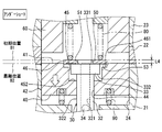
- FIG. 2 is a schematic vertical sectional view showing the configuration of a fuel injection valve
- FIG. 3 is a view showing an open state of the fuel injection valve
- FIG. 4 is a view showing a state during the opening of the fuel injection valve
- FIG. 5 is a view showing a state in which the fuel injection valve has been opened
- FIG. 6 is a view showing a state in which the needle of the fuel injection valve overshoots
- FIG. 7 is a view showing a state where the movable core of the fuel injection valve undershoots
- FIG. 1 is a schematic view showing a configuration of a combustion system in a first embodiment
- FIG. 2 is a schematic vertical sectional view showing the configuration of a fuel injection valve
- FIG. 3 is a view showing an open state of the fuel injection valve
- FIG. 4 is a view showing a state during the opening of the fuel injection valve
- FIG. 5 is a
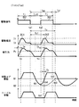
- FIG. 8 is a timing chart showing the behavior of the movable core in the case where irregular injection does not occur because the signal interval is longer than the reference return period
- FIG. 9 is a timing chart showing the behavior of the movable core when irregular injection does not occur because the signal interval is shorter than the allowable period
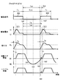
- FIG. 10 is a timing chart showing the behavior of the movable core when irregular injection occurs
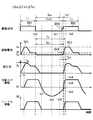
- FIG. 11 is a timing chart showing the behavior of the movable core when irregular injection ceases to occur due to intermediate drive energization
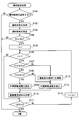
- FIG. 12 is a flowchart showing the procedure of the injection setting process
- FIG. 13 is a timing chart showing how the drive current changes in the second embodiment
- FIG. 14 is a flowchart showing the procedure of the injection setting process
- FIG. 15 is a timing chart showing another variation of drive current
- FIG. 16 is a timing chart showing how the drive current changes in the third embodiment
- FIG. 17 is a timing chart showing the behavior of the movable core when irregular injection ceases to occur due to pre-drive energization
- FIG. 18 is a flowchart showing the procedure of the injection setting process.
- the injector 100 shown in FIG. 1 is included in a combustion system 110.
- the combustion system 110 includes an internal combustion engine 111, an intake pipe 112, and an exhaust pipe 113.
- the internal combustion engine 111 is an ignition engine, for example, a gasoline engine.
- the intake pipe 112 supplies intake air to the combustion chamber 111 a of the internal combustion engine 111, and the exhaust pipe 113 discharges the exhaust gas from the combustion chamber 111 a.
- the internal combustion engine 111 includes a cylinder 114, a piston 115, an intake valve 116, an exhaust valve 117, an injector 100, an ignition plug 122, an intake pressure sensor 123, a crank angle sensor 124 and an ECU 125.
- the piston 115 is provided in the cylinder 114 so as to be capable of reciprocating.
- the combustion chamber 111a is in communication with the intake pipe 112 and the exhaust pipe 113 via the intake port and the exhaust port, the intake valve 116 opens and closes the intake port, and the exhaust valve 117 opens and closes the exhaust port.
- the injector 100 is a fuel injection valve that injects fuel, and directly injects the fuel into the combustion chamber 111a.
- the spark plug 122 ignites the mixture of the intake air and the fuel in the combustion chamber 111a.
- the intake pressure sensor 123 is attached to the intake pipe 112 and detects the pressure in the intake pipe 112 as an intake pressure.
- the crank angle sensor 124 is attached to the crankshaft and detects the crank angle.
- An ECU (Engine Control Unit) 124 is a control device that controls the operation of the combustion system 110.
- the ECU 125 has a computer configured to include a processor 124a, a storage unit 124b, an input / output interface, and the like.
- the storage unit 124 b may be a storage medium such as a RAM.
- a program for performing operation control of the combustion system 110 is stored in the storage unit 124b or the like, and this program is executed by the processor 124a.
- the ECU 125 is electrically connected to various detection units such as the intake pressure sensor 123 and the crank angle sensor 124, and based on the detection results of these detection units, the operation control of the spark plug 122 and the opening degree control of the throttle valve Perform engine control.
- the ECU 125 may refer to the intake pressure sensor 123 or the ECU 125 as an engine control device, and may refer to the combustion system 110 as an engine control system.
- the combustion system 110 includes a fuel supply system 130 for supplying fuel to the combustion chamber 111a.
- the fuel supply system 130 includes a fuel tank 131, a fuel pump 132, a fuel delivery 133, an injection pressure sensor 134, and a control unit 135, in addition to the injector 100 described above.
- the fuel tank 131 stores fuel
- the fuel pump 132 is a high pressure pump that supplies the fuel in the fuel tank 131 to the injector 100 in a state where the fuel pressure is increased.
- the combustion system 110 includes a plurality of injectors 100, and the fuel delivery 133 distributes fuel to the injectors 100.
- the injection pressure sensor 134 is provided in the fuel delivery 133, and detects the pressure of the fuel supplied to the injector 100 as the injection pressure.
- the control unit 135 is a control device that controls the operation of the fuel supply system 130.
- the control unit 135 includes a computer configured to include a processor 135a, a storage unit 135b, an input / output interface, and the like.
- a storage medium such as a RAM may be mentioned.
- a program for controlling the operation of the injector 100 is stored in the storage unit 135b or the like, and this program is executed by the processor 135a.
- the control unit 135 is electrically connected to various detection units such as the injection pressure sensor 134, and performs operation control of the injector 100 and the fuel pump 132 as fuel injection control based on the detection results of these detection units.
- the control unit 135 corresponds to a fuel injection control device that controls the operation of the injector 100 which is a fuel injection valve.
- a sensor control unit SCU
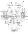
- the injector 100 shown in FIG. 2 includes a housing 20, a nozzle portion 10, a fixed core 60, a movable core 40, a needle 30 as a valve body, a movable plate 50, a first spring 80, a second spring 90, a coil 70 and the like.
- a drive unit for moving the needle 30 includes the movable core 40, the fixed core 60, the coil 70, and the first spring 80.
- the housing 20 includes a first cylindrical member 21, a second cylindrical member 22, a third cylindrical member 23, an outer peripheral member 25, and a resin mold portion 26.
- the first cylindrical member 21, the second cylindrical member 22 and the third cylindrical member 23 are all formed in a substantially cylindrical shape, and are coaxial in the order of the first cylindrical member 21, the second cylindrical member 22 and the third cylindrical member 23. Arranged and connected to each other.
- the outer peripheral member 25 is in contact with the outer peripheral surfaces of the first cylindrical member 21 and the third cylindrical member 23.
- the first cylindrical member 21, the third cylindrical member 23 and the outer peripheral member 25 are made of, for example, a magnetic material such as ferritic stainless steel.
- the second cylindrical member 22 is formed of a nonmagnetic material such as austenitic stainless steel, for example.
- the nozzle portion 10 is provided at an end portion of the first cylindrical member 21 and is formed in a disk shape made of metal. At the center of the nozzle portion 10, an injection hole 11 penetrating the nozzle portion 10 in the plate thickness direction is formed. Further, an annular valve seat 12 is formed on one surface of the nozzle portion 10 so as to surround the injection hole 11. The nozzle portion 10 is connected to the first cylindrical member 21 so that the side wall is fitted to the inner wall of the first cylindrical member 21.
- the fixed core 60 is provided at the end of the third cylindrical member 23, and is formed in a substantially cylindrical shape, for example, by a magnetic material such as ferritic stainless steel.
- the fixed core 60 is provided inside the housing 20.
- the fixed core 60 and the nozzle portion 10 are fixed to the housing 20 by welding.
- the needle 30 is formed in a rod shape, for example, with a metal such as martensitic stainless steel.
- the needle 30 is accommodated in the housing 20 so as to be reciprocally movable in the axial direction.
- the needle 30 is formed at a rod-like main body 32 extending in the axial direction, a seal portion 31 formed at an end of the main body 32 on the nozzle 10 side, and an end of the main body 32 opposite to the nozzle 10 side. And a ridge portion 33.
- the needle 30 opens and closes the injection hole 11 by the seal portion 31 moving away from the valve seat 12 (i.e., leaving) or contacting (i.e., seating) the valve seat 12.
- valve opening direction the direction in which the needle 30 separates from the valve seat 12
- valve closing direction the direction in which the needle 30 abuts on the valve seat 12
- the flange 33 side of the main body 32 is formed in a hollow cylindrical shape, and a hole 34 connecting the inner wall 321 and the outer wall 322 of the main body 32 is formed.
- the collar portion 33 is in the shape of a disc that expands toward the inner wall 24 of the housing 20.
- the movable core 40 is formed in a substantially cylindrical shape, for example, by a magnetic material such as ferritic stainless steel.
- the movable core 40 is accommodated inside the housing 20 so as to be capable of reciprocating between the fixed core 60 and the nozzle unit 10.
- a through hole 44 is formed at the center of the movable core 40.
- the inner wall of the through hole 44 of the movable core 40 and the outer wall 322 of the main body 32 of the needle 30 can slide, and the outer wall 42 of the movable core 40 and the inner wall 24 of the housing 20 can slide.
- the movable core 40 can reciprocate inside the housing 20 while sliding on the needle 30 and the housing 20.
- the movable core 40 has an accommodation recess 45 formed on the end surface 41 on the fixed core 60 side so as to annularly expand radially outward from the inner wall of the through hole 44. Further, the movable core 40 has an insertion groove 46 formed on the end surface 41 on the fixed core 60 side so as to annularly expand radially outward from the end opposite to the bottom wall 452 of the accommodation recess 45.
- the collar 33 of the needle 30 is housed in the housing recess 45, and the movable plate 50, which will be described later, is fitted in the fitting groove 46.
- the movable plate 50 is formed of, for example, a metal such as martensitic stainless steel in a disk shape having a diameter larger than that of the housing recess 45 and has a hole 51 at the center.
- the movable plate 50 is provided on the opposite side of the movable core 40 to the nozzle portion 10 so as to be able to abut on the movable core 40 and the collar portion 33 of the needle 30.
- the movable plate 50 is provided so as to be insertable into the insertion groove 46.
- the coil 70 is formed in a substantially cylindrical shape, and provided so as to surround the radially outer side of the second cylindrical member 22 and the third cylindrical member 23.
- a resin mold portion 26 is filled between the first cylindrical member 21, the second cylindrical member 22, the third cylindrical member 23 and the outer peripheral member 25.
- the first spring 80 contacts the movable plate 50 to apply an elastic force to bias the movable core 40 and the needle 30 in the valve closing direction.
- the second spring 90 abuts on the movable core 40 to apply an elastic force to urge the movable plate 50 toward the fixed core 60 (that is, the valve opening direction).
- the biasing force of the first spring 80 is set larger than the biasing force of the second spring 90. Therefore, in a state where power is not supplied to the coil 70, the needle 30 is in a closed state in which the seal portion 31 abuts on the valve seat 12.
- the first spring 80 corresponds to a valve body biasing portion that biases the valve body
- the second spring 90 corresponds to a core biasing portion that biases the fixed core 60.
- the second spring 90 is provided such that the first end abuts on the bottom surface of the groove 431 formed on the end face 43 on the injection hole 11 side of the movable core 40.
- the second end of the second spring 90 is in contact with an annular step surface 211 formed inside the first cylindrical member 21 of the housing 20.
- the second spring 90 has an axially extending force.
- the second spring 90 biases the movable plate 50 toward the fixed core 60 by biasing the movable core 40.
- the position of the movable core 40 in this case is referred to as an initial position B1.
- the end surface 43 of the movable core 40 is separated from the stepped surface of the first cylindrical member 21 in the axial direction opposite to the injection hole 11. Therefore, the movable core 40 can move to the injection hole 11 side more than the initial position B1.
- the movable plate 50 abuts on both the needle 30 and the movable core 40 by the biasing force of the first spring 80 and the second spring 90. Specifically, the lower end surface 53 of the movable plate 50 abuts on the end surface 331 of the collar 33 of the needle 30 and the bottom wall 461 of the insertion groove 46 of the movable core 40.
- the movable core 40 and the needle 30 in this case are in a closed state.
- the position of the needle 30 in this case is referred to as a valve closing position A1.
- the axial length of the collar 33 is L1
- the axial distance between the lower end surface 53 of the movable plate 50 and the bottom wall 452 of the housing recess 45 is L2.
- the flange 33, the movable plate 50, the housing recess 45, and the fitting groove 46 are formed to satisfy the relationship of L1 ⁇ L2.
- the axial distance between the lower end face 332 of the collar 33 and the bottom wall 452 of the housing recess 45 is G1, and the axial distance between the end face 41 of the movable core 40 and the end face of the fixed core 60 on the movable core 40 side.
- a substantially cylindrical fuel introduction pipe 62 is press-fit and welded to the end of the third cylindrical member 23.
- the fuel flowing from the fuel introduction pipe 62 flows through the fixed core 60, the hole 51 of the movable plate 50, the inside of the main body 32 of the needle 30, the hole 34 of the needle 30, and between the first cylindrical member 21 and the needle 30 in this order. Do. In the state where the needle 30 is opened by energization of the coil 70, the fuel which has flowed as described above is injected from the injection hole 11 after flowing between the seal portion 31 and the valve seat 12.
- the first spring 80 biases the needle 30 in the valve closing direction by biasing the movable plate 50, and the second spring 90 is biased.
- the movable core 40 is biased to the fixed core 60 side.
- the lower end surface 53 of the movable plate 50 abuts on the end surface 331 of the collar 33 of the needle 30 and the bottom wall 461 of the insertion groove 46 of the movable core 40, and L1 ⁇ L2 and G1 ⁇ G2 as described above There is.
- the seal portion 31 of the needle 30 is in the closed state in which the seal portion 31 is seated on the valve seat 12, and the injection hole 11 is in the closed state.
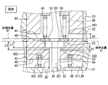
- the movable core 40 When the coil 70 is energized, as shown in FIG. 4, the movable core 40 is attracted to the fixed core 60 and moves to the fixed core 60 side.
- the movable plate 50 is pushed by the movable core 40 and moves toward the first spring 80 against the biasing force of the first spring 80.
- the movable core 40 accelerates by a predetermined distance G1 and collides with the lower end surface 332 of the hook portion 33 of the needle 30 in the state of having kinetic energy of the acceleration distance. Due to the collision, the needle 30 rapidly starts to move in the valve opening direction, the seal portion 31 is separated from the valve seat 12, and the fuel is injected from the injection hole 11.
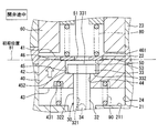
- the movable core 40 continues to move after colliding with the needle 30, and collides with the fixed core 60 as shown in FIG. That is, the movement of the movable core 40 is restricted.
- the needle 30 is biased in the valve opening direction by the movable core 40 in a state where the collar 33 engages with the bottom wall 452.
- the period in which the movable core 40 collides with the fixed core 60 after the movable core 40 collides with the needle 30 is a period during which the movable core 40 collides with the needle 30.
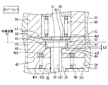
- the needle 30 leaves the movable core 40 as shown in FIG. 6 and continues moving against the elastic force of the first spring 80 by inertia.
- the first spring 80 pressed against the needle 30 via the movable plate 50 pushes the movable plate 50 and the needle 30 back toward the valve-closing direction to move the spring after the first spring 80 is compressed to the limit.
- the movable plate 50 and the needle 30 thus pushed back stop moving in the state of FIG.
- the overshoot amount L3 is a distance between the needle 30 and the movable core 40 in the axial direction. Specifically, it is the distance in the axial direction from the lower end surface 332 of the collar portion 33 to the bottom wall 452 of the housing recess 45.
- the electromagnetic attraction force decreases, and when the valve opening holding force is reduced, the movable plate 50, the movable core 40 and the needle 30 move in the valve closing direction.
- the movable plate 50 is biased toward the needle 30 by the first spring 80, thereby starting the movement of the movable core in the valve closing direction.
- the movable plate 50 abuts on the hook portion 33 of the needle 30 to bias the needle 30 in the valve closing direction.
- the elastic force of the first spring 80 is transmitted to the needle 30 via the movable plate 50, and the elastic force causes the needle 30 to start the valve closing operation.
- the movement of the needle 30 moving in the valve closing direction is stopped when the seal portion 31 abuts on the valve seat 12.
- the movable core 40 is separated from the movable plate 50 as shown in FIG. 7 and is closed against the elastic force of the second spring 90 by inertia.
- the movable core 40 passes through the initial position B1 and reaches the most separated position B2 by the second spring 90 being contracted, it starts to move in the valve opening direction by the second spring 90 being extended this time. And return to the initial position B1.
- the movable core 40 returned from the most separated position B2 to the initial position B1 stops at the initial position B1 in a state of being caught by the movable plate 50 as shown in FIG. 3.
- the state in which the movable core 40 has moved to the most separated position B2 side from the initial position B1 is referred to as an undershoot.
- a state where the movable core 40 in the undershoot moves toward the valve opening direction from the farthest position B2 to the initial position B1 is referred to as core boost, and the movable core 40 in the core boost restores the second spring 90. It is moving by force.
- the undershoot amount L4 is the axial direction of the movable core 40 and the movable plate 50. It becomes the separation distance in Specifically, the distance is an axial distance between the end surface 41 of the movable core 40 on the stationary core 60 side and the end surface of the movable plate 50 on the stationary core 60 side.
- the undershoot amount L4 is increasing, the movable core 40 is in the process of being moved away from the initial position B1, and the second spring 90 is being contracted by the inertia of the movable core 40.
- the undershoot amount L4 is decreasing, the movable core 40 is in the process of approaching the initial position B1, and the second spring 90 is in the process of being stretched by its own elastic force.
- the movement start timing of the movable plate 50 starts the movement of the movable core 40 regardless of the valve closing and the valve opening. It is the same as the timing.
- the movement start timing of the needle 30 is later than the movement start timing of the movable core 40 in any case of valve closing and valve opening.
- the deviation of the movement start timing between the needle 30 and the movable core 40 is ignored, and the movement of the needle 30 is also started with the movement start of the movable core 40. This is because the first spring 80 directly biases the needle 30 without the movable plate 50 provided, and the hook portion 33 of the needle 30 is caught on the movable core 40 when the movable core 40 is in the initial position. It is possible to realize by the configuration.
- the movable plate 50 is configured separately from the movable core 40 and provides a moving member that moves with the movable core 40.
- the movable plate 50 is pushed and moved by the movable core 40 in the valve opening direction, and is pushed and moved by the first spring 80 in the valve closing direction.
- the movable plate 50 when moved by being pressed by the first spring 80, the movable plate 50 functions as a valve-closing force transmission member that transmits the elastic force of the first spring 80 to the needle 30.
- the control unit 135 causes the injector 100 to perform fuel injection by outputting a drive signal as an electrical signal to the injector 100.
- the coil 70 is energized in accordance with the drive signal.
- a drive current corresponding to the drive signal flows in the coil 70.
- the control unit 135 can perform multiple fuel injections by the injector 100 during one combustion cycle as multi-stage injection.
- the drive signal can also be referred to as a drive command signal or an injection command signal.
- the behavior of the movable core 40 when multistage injection is performed will be described with reference to FIGS. 8 to 11.
- the transition of the drive signal to the high level is referred to as ON
- the transition of the drive signal to the low level is referred to as OFF.
- the first drive signal DS1 is turned off at timing ta1 and is set to timing ta2.
- the second signal C2 is turned on.
- the signal interval Tint is a period from the OFF timing ta1 of the first drive signal DS1 to the ON timing ta2 of the second drive signal DS2. is there.
- a drive instruction period Tj the drive instruction period Tj is different if the first drive signal DS1 and the second drive signal DS2 have the same length. Sometimes it's length.
- the signal interval Tint corresponds to the injection interval.
- a first drive energization DI1 through which a drive current according to a first drive signal DS1 flows, and a second drive energization DI2 through which a drive current according to a second drive signal DS2 flows There is.
- the drive current associated with the drive energization DI1 and DI2 gradually increases to the first drive value Ia with the ON of the drive signals DS1 and DS2, and is maintained at this first drive value Ia for a certain period.
- the drive signals DS1 and DS2 include information for changing the drive current associated with the drive energization DI1 and DI2 to the first drive value Ia and the second drive value Ib. Further, the first drive energization DI1 corresponds to the first energization, and the second drive energization DI2 corresponds to the second energization.
- the electromagnetic attraction generated by the drive energization DI1, DI2 gradually rises up to the movable value Pc by gradually increasing with the increase of the drive energization DI1, DI2, and the movable core 40 is opened by the electromagnetic attraction reaching the movable value Pc. Start moving in the direction. As a result, the needle 30 is opened to start fuel injection.
- the movable value Pc is, for example, a value capable of overcoming the biasing force of the first spring 80.
- the timing when the electromagnetic attraction force reaches the movable value Pc is referred to as rising timing tc, and the period required for the electromagnetic attraction force to reach the movable value Pc from the timing when the drive signals DS1 and DS2 are turned ON is referred to as a rising period To.
- the period from the ON timing ta2 to the rising timing tc corresponds to the rising period To.
- the drive signals DS1 and DS2 and the drive energization DI1 and DI2 are set such that the rising periods To of the drive signals DS1 and DS2 are the same.
- the vertical axis represents the amount of movement of the movable core 40 and the needle 30, and an increase in the amount of movement indicates a movement in the valve opening direction. Indicates the movement toward the valve closing direction.
- the movable core 40 and the needle 30 start to move in the valve closing direction accordingly, and the undershoot of the movable core 40 occurs as described above.
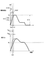
- the movable core 40 that undershoots passes through the initial position B1 in the valve closing direction at timing tb1, and reaches the most separated position B2 at timing tb2. Thereafter, the movable core 40 returns to the initial position B1 at timing tb3 by moving in the valve opening direction.
- the timing tb3 is referred to as a reference return timing tb3, and the period from the OFF timing ta1 of the first drive signal DS1 to the reference return timing tb3 is referred to as a reference return period Tu. Further, the timing tb2 at which the movable core 40 reaches the most separated position B2 is referred to as the most separated timing tb2. Furthermore, when timing tb1 at which the undershoot of the movable core 40 starts is referred to as start timing tb1, a period from the start timing tb1 to the reference return timing tb3 corresponds to an undershoot period in which the movable core 40 undershoots.
- the electromagnetic attraction force is not applied to the movable core 40 in the undershoot.
- the reference return timing tb3 is earlier than the ON timing ta2 of the second drive signal DS2
- the signal interval Tint is longer than the reference return period Tu.
- the reference return period Tu includes a specific period To1 having the same length as the rising period To.
- the specific period To1 is a period between the specific timing tb5 and the reference return timing tb3.
- the reference return period Tu includes an allowable period Tuo having a length obtained by subtracting the specific period To1 from the reference return period Tu.
- the allowable period Tuo is a period between the OFF timing ta1 of the first drive signal DS1 and the specific timing tb5, and is shorter than the reference return period Tu.
- the reference return timing tb3 and the reference return period Tu by storing past information and experimental information in the storage unit 135b. Also, it is possible to predict the rising period To of the electromagnetic attraction force due to the second drive energization DI2.
- the reference return timing tb3 can also be referred to as a predicted return timing
- the reference return period Tu and the rising period To can also be referred to as a predicted return period and a predicted rising period.
- the movable core 40 in the undershoot in the predicted allowable period Tuo is electromagnetically Suction is applied.
- the signal interval Tint is shorter than the reference return period Tu.
- the signal interval Tint is shorter than the permissible period Tuo.
- the movable core 40 is forcibly pulled back to the initial position B1 side in the allowable period Tuo, so that the undershoot period is shortened.
- the timing at which the movable core 40 returns to the initial position B1 is the core return timing tb4 earlier than the reference return timing tb3.
- the period required for the movable core 40 to return to the initial position B1 from the OFF timing ta1 of the first drive signal DS1 is the core return period Tu1 shorter than the reference return period Tu.
- the core return period Tu1 corresponds to the additional return period
- the core return timing tb4 corresponds to the additional return timing.
- the movable core 40 is not returned to the initial position B1 by the rise timing tc, and the core return timing tb4 is later than the rise timing tc.
- the electromagnetic attraction force increases to at least the movable value Pc.
- the movable core 40 collides with the needle 30 by returning to the initial position B1, and moves the needle 30 together with the needle 30 through the initial position B1 by the electromagnetic attraction force equal to or more than the movable value Pc. Open 30.
- the movable core 40 starts moving from the initial position B1 in the valve opening direction with a delay of the core delay period Tz. Therefore, if the drive command period Tj is constant, the fuel injection amount from the injection hole 11 is reduced by the core delay period Tz as compared with the case where the core delay period Tz is zero.
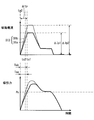
- the movable core during undershooting is performed as in the case where the reference return timing tb3 is included in the rising period To.
- a magnetic attraction is applied to 40.
- the signal interval Tint is less than or equal to the reference return period Tu because the reference return timing tb3 is later than the ON timing ta2 of the second drive signal DS2.
- the signal interval Tint is equal to or longer than the allowable period Tuo.
- the movable core 40 when the reference return timing tb3 is included in the rising period To, the movable core 40 is forcibly pulled back to the initial position B1 in the specific period To1, so that the undershoot period is shortened. In this case, as in the case where the reference return timing tb3 is later than the rising period To (see FIG. 9), the movable core 40 returns to the initial position B1 at a core return timing tb4 earlier than the reference return timing tb3. As a result, the core return period Tu1 becomes shorter than the reference return period Tu.
- the reason why the undershoot period is shortened in the specific period To1 is that the movable core 40 accelerates due to the electromagnetic attraction force being further applied to the movable core 40 in the core boost.
- the electromagnetic attraction force applied to the movable core 40 in the specific period To1 has not yet reached the movable value Pc, and if the movable core 40 is stopped at the initial position B1, movement can not be started. It is a relatively small force.
- the accelerated movable core 40 temporarily returns to the initial position B1 and collides with the needle 30 so that the needle 30 temporarily passes through the initial position B1 and moves toward the valve-opening side, but the impact force due to the collision By damping, it moves to the valve closing side again and returns to the initial position B1.
- the temporary movement of the movable core 40 toward the valve-opening side from the initial position B1 is referred to as an irregular movement.
- the needle 30 is also temporarily opened. Actuation causes irregular injection in which fuel is unintentionally injected.
- the reference return timing tb3 is included in the rising period To, the inventor of the present invention performs the irregular movement of the movable core 40 or the fuel between the fuel injection by the first drive signal DS1 and the fuel injection by the second drive signal DS2. We found that irregular injection is likely to occur.
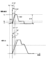
- an intermediate drive signal DS3 as a drive signal is output from the control unit 135 in the allowable period Tuo.
- the intermediate drive signal DS3 is turned on at timing td1 in the signal interval Tint and turned off at timing td2.
- this intermediate command period Tk is between the undershoot start timing tb1 and the most separate timing tb2.
- the intermediate drive signal DS3 is turned on after the start of the undershoot of the movable core 40, and the intermediate drive signal DS3 is turned off before the movable core 40 reaches the most separated position B2.
- a current due to the intermediate drive energization DI3 according to the intermediate drive signal DS3 flows.
- the current due to the intermediate drive energization DI3 gradually increases to the third drive value Ic with the turning on of the intermediate drive signal DS3, and gradually decreases to zero after reaching the third drive value Ic.
- the third drive value Ic is a value between the first drive value Ia and the second drive value Ib.
- the intermediate drive signal DS3 includes information for changing the drive current associated with the intermediate drive energization DI3 to the third drive value Ic.
- the intermediate drive energization DI3 corresponds to additional energization, and may be held for a certain period of time at the third drive value Ic, and may be reduced as soon as the third drive value Ic is reached.
- the electromagnetic attraction force generated by the intermediate drive energization DI3 gradually increases with the increase of the intermediate drive energization DI3, and gradually decreases with the decrease of the intermediate drive energization DI3.
- This electromagnetic attraction does not reach the movable value Pc, unlike the electromagnetic attraction caused by the drive energization DI1 and DI2.
- the movable core 40 is forcibly pulled back to the initial position B1, the undershoot period is Becomes shorter.
- the movable core 40 returns to the initial position B1 at the core return timing tb4 earlier than the reference return timing tb3 and the core return period Tu1 is a reference It is shorter than the return period Tu.
- the intermediate command period Tk and the third drive value Ic are set such that the core return timing tb4 is earlier than the specific period To1.
- the electromagnetic attraction force is not applied to the movable core 40 in the undershoot. . Therefore, the occurrence of the irregular movement of the movable core 40 due to the electromagnetic attraction is suppressed.
- the core return timing tb4 is included in the allowable period Tuo, and the core return period Tu1 is shorter than the allowable period Tuo.
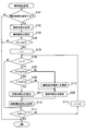
- the control unit 135 performs an injection setting process to set an injection mode when the fuel is injected from the injector 100. This process will be described with reference to the flowchart of FIG.
- the control unit 135 performs fuel injection control for the injector 100 by performing operation control of the injector 100 according to the injection mode set in the injection setting process.
- the flowchart of FIG. 12 also shows a fuel injection control method.
- step S101 it is determined whether the fuel injection mode is set for one combustion cycle.
- the process proceeds to step S102, and the operating state of the internal combustion engine 111 is acquired.
- intake pressure detected using the detection signal of the intake pressure sensor 123, engine rotational speed detected using the detection signal of the crank angle sensor 124, etc. are acquired as information indicating the operating state of the internal combustion engine 111. Do.
- step S103 the fuel injection mode is set. Then, information on the injection mode is stored in the storage unit 135b.
- the injection mode the injection amount Q, the drive command period Tj, the injection start timing SOI, the injection end timing EOI, the injection pressure Pf, and the number of injections Ninj are set.
- the injection amount Q is the total amount of fuel injected in one combustion cycle
- the drive command period Tj is a period during which the drive signal is ON as described above.
- the injection start timing SOI is the timing to start the first fuel injection in one combustion cycle
- the injection end timing EOI is the timing to end the last fuel injection in one combustion cycle.
- the injection pressure Pf is the pressure of fuel injected from the injector 100
- the number of injections Ninj is the number of times of fuel injection in one combustion cycle.
- the injection mode when the number of times of injection Ninj is a plurality of times, the above-described signal interval Tint and the drive command period Tj are set. In addition, drive values Ia and Ib of the drive current are also set.
- step S104 it is determined whether the number of injections Ninj is a plurality of times. When the number of times of injection Ninj is one, the main injection setting process ends. If the number of injections Ninj is a plurality of times, the process proceeds to step S105 as multistage injection, and if the number of injections Ninj is one, the present injection setting processing is ended as it is. In step S105, the counter i is set to "1" in order to individually recognize a plurality of fuel injections.
- steps S106 to S114 an update process is performed to update the setting content regarding the drive current for each of the plurality of fuel injections in the multistage injection.
- the setting content of the drive current for the i-th fuel injection is updated for the counter i. That is, the injection setting for the i-th shot is performed.
- step S106 it is determined whether the counter i is larger than "1". If the counter i is not larger than "1”, the process proceeds to step S111, assuming that the update process is not performed for the first fuel injection in the multistage injection. This means that the setting content of the drive current already set in step S103 is adopted for the first fuel injection.
- step S111 it is determined whether the counter i has reached the number of injections Ninj. If the counter i has reached the number of injections Ninj, it is assumed that the update process has been performed for all of the plurality of fuel injections in the multistage injection, and the present injection setting process is ended. If the counter i has not reached the number of injections Ninj, the process proceeds to step S113, and the counter i is incremented by one. Thereafter, the process returns to step S106. Here, the processing of steps S106 to S113 is repeated until the counter i reaches the number of injections Ninj.
- step S107 it is determined whether the signal interval Tint is greater than or equal to the allowable period Tuo.
- energization for fuel injection targeted in the previous processing is set as a first drive energization DI1
- current for fuel injection targeted in the present processing is set as a second drive energization DI2.
- the drive values Ia and Ib, the drive command period Tj, the signal interval Tint, and the rise period To are obtained as parameters for the drive energization DI1 and DI2, and the tolerance period Tuo is calculated as a predicted value using these parameters.
- the rising period To due to the second drive energization DI2 is also acquired as a predicted value.
- step S108 the reference return period Tu is calculated as a predicted value using the same parameters as step S107, and it is determined whether the signal interval Tint is less than or equal to the reference return period Tu.
- the determinations in steps S107 and S108 are both positive, as shown in FIG. 10, it is assumed that Tuo ⁇ Tint ⁇ Tu, which is a condition that irregular injection tends to occur, and the process proceeds to step S109.
- steps S107 and S108 also determine whether or not the reference return timing tb3 is included in the rising period To due to the second drive energization DI2. Therefore, when the reference return timing tb3 is included in the rising period To, the process proceeds to step S109.
- step S109 an intermediate drive energization DI3 is added between the first drive energization DI1 and the second drive energization DI2.
- the timing of the intermediate drive energization DI3, the energization period, the third drive value Ic, and the like are set such that the core return timing tb4 is earlier than the specific period To1. That is, the waveform of the drive current accompanying the intermediate drive energization DI3 is set.
- the ON timing td1, the OFF timing td2, the intermediate command period Tk, and the like are also set for the intermediate drive signal DS3 so as to realize the waveform of the drive current.
- step S110 information relating to the drive current such as the waveform of the drive current accompanying the second drive energization DI2 and the waveform of the drive current accompanying the intermediate drive energization DI3 is stored in the storage unit 135b in association with the i-th fuel injection.
- step S107 If it is determined in step S107 that the signal interval Tint is not longer than the allowable period Tuo, as shown in FIG. 9, it is determined that Tint ⁇ Tuo, which is a condition under which irregular injection is less likely to occur, and the process proceeds to step S112.
- Tint ⁇ Tuo is satisfied, as described above, the time for the second drive energization DI2 to flow through the coil 70 is shortened by the amount of the core delay period Tz, and the fuel injection amount by the second drive energization DI2 is intended. May decrease without Therefore, in step S112, the drive command period Tj of the second drive signal DS2 is updated to correct the power supply period of the second drive power supply DI2.
- the drive command period Tj is set such that the period in which the second drive energization DI2 flows through the coil 70 becomes longer by the core delay period Tz.
- the control unit 135 has a function of executing the process of each step in the injection setting process.
- the function of executing the process of step S109 corresponds to the additional energizing unit.
- the intermediate drive energization DI3 is performed.
- the core return timing tb4 at which the movable core 40 actually returns to the initial position can be advanced earlier than the specific timing tb5.
- the signal interval Tint is longer than the core return period Tu1
- the condition for the occurrence of the irregular injection that the signal interval Tint is not less than the allowable period Tuo and not more than the reference return period Tu is that the reference return timing tb3 by the first drive energization DI1 is the rise period To in the second drive energization DI2. It is also included. Therefore, performing the intermediate drive energization DI3 causes the core return timing tb4 to be earlier than the rising period To of the second drive energization DI2. As described above, even from the viewpoint of whether or not the core return timing tb4 is earlier than the rising period To, performing the intermediate drive energization DI3 avoids the occurrence condition of the irregular injection.
- the intermediate drive energization DI3 when the signal interval Tint is longer than the reference return period Tu, the intermediate drive energization DI3 is not performed.
- the reference return period Tu is shortened to the core return period Tu1, which may result in the occurrence condition of the irregular injection being satisfied. is there. That is, there is a possibility that the condition that the signal interval Tint is equal to or more than the allowable period Tuo and equal to or less than the core return period Tu1 may be met.
- the intermediate drive energization DI3 is inhibited, and the movable core 40 is accelerated by the electromagnetic attraction force, which corresponds to the condition for generating the irregular injection. That can be reliably avoided.
- the content of the intermediate drive energization DI3 is set such that the core return timing tb4 is earlier than the specific period To1. Therefore, it is possible to avoid the situation where the signal interval Tint is not shorter than the allowable period Tuo despite the addition of the intermediate drive energization DI3. This makes it possible to more reliably suppress the occurrence of irregular injection.
- the core return timing tb4 is earlier than the specific period To1 means that the core return timing tb4 is earlier than the rising period To associated with the second drive energization DI2.
- the core return timing tb4 is earlier than the rising period To, it is possible to perform the intermediate drive energization DI3 so that the core return timing tb4 is earlier than the rising period To. It will avoid the occurrence condition.
- the electromagnetic attraction force is applied to the movable core 40 while the needle 30 is in the valve closing operation. It can be avoided.
- the electromagnetic attraction is applied to the movable core 40 at a timing earlier than the undershoot start timing tb1
- the movement of the movable core 40 which is about to return to the initial position B1 in accordance with the valve closing operation of the needle 30 is There is a possibility that it may be disturbed by electromagnetic attraction.
- the intermediate drive energization DI3 is performed at a timing that does not disturb the valve closing operation of the needle 30. Therefore, it is possible to appropriately suppress the valve closing operation of the needle 30 by the first drive energization DI1, and to suppress the occurrence of the irregular injection of the fuel by the second drive energization DI2.
- the control unit 135 can select the normal energization DIa not shortening the rising period To and the shortened energization DIb shortening the rising period To.
- the shortening gradient Sb which is the current gradient for the shortening energization DIb, corresponds to that for the normal energization DIa.
- the current gradient is larger than the normal gradient Sa.
- the current gradient is a ratio of a change amount ⁇ Ip until the drive current reaches the maximum value with respect to a required period ⁇ tp required for the drive current to reach the maximum value.
- the amount of change ⁇ Ip is the same for the normal energization DIa and the shortening energization DIb, and the required period ⁇ tp is shorter in the shortening energization DIb than in the normal energization DIa.
- the required period ⁇ tp of the normal energization DIa is called a normal required period ⁇ tp1 and the required period ⁇ tp of the shortened energization DIb is called a shortened required period ⁇ tp2
- the shortened required period ⁇ tp2 is shorter than the normal required period ⁇ tp1.
- the relationship of ⁇ Ip / ⁇ tp2> ⁇ Ip / ⁇ tp1 holds.
- the maximum value of the drive current is the first drive value Ia
- the amount of change ⁇ Ip is the same value as the first drive value Ia for both the normal energization DIa and the shortened energization DIb.
- the electromagnetic attraction force reaches the movable value Pc at the normal rise timing tc1, and the period required for the arrival is referred to as the normal rise period Toa.
- the electromagnetic attractive force normally reaches the movable value Pc at the shortening rising timing tc2 earlier than the rising timing tc1, and the period required for the reaching is referred to as a shortening rising period Tob.
- the shortened rising period Tob is shorter than the normal rising period Toa.
- the control unit 135 selects the normal conduction DIa and the short conduction DIb by selecting the voltage applied to the coil 70. Information on the voltage applied to the coil 70 is included in the drive signal.
- the normal energization DIa corresponds to the occurrence condition of irregular injection Tuo ⁇ Tint ⁇ Tu because the normal rising period Toa includes the reference return timing tb3.
- the reduced energization DIb does not fall under the irregular injection condition of Tuo ⁇ Tint ⁇ Tu because the reduced rising period Tob does not include the reference return timing tb3. For this reason, when the rising period To is shortened by selecting not the normal conduction DIa but the short conduction DIb as the second drive conduction DI2, it is possible to avoid the occurrence condition of irregular injection Tuo ⁇ Tint ⁇ Tu. become.
- the control unit 135 basically executes the same injection setting process as the first embodiment. However, in the present embodiment, steps S201 and S202 are executed instead of steps S109 and S113 in the first embodiment.
- step S201 the shortening gradient Sb is set by selecting the shortening energization DIb as the second driving energization DI2. That is, the waveform of the drive current associated with the second drive energization DI2 is set.
- setting the shortening gradient Sb instead of the normal gradient Sa can reduce the possibility that the reference return timing tb3 is included in the shortening rising period Tob.
- the function of executing the process of step S201 corresponds to the change energizing unit.
- step S202 the normal gradient Sa is set by selecting the normal energization DIa as the second drive energization DI2.
- the normal gradient Sa is set by selecting the normal energization DIa as the second drive energization DI2.
- step S110 the process proceeds to step S110, and this time, as information on the waveform of the drive current accompanying the second drive energization DI2, the normal gradient Sa etc. of the drive current accompanying the normal energization DIa is made to correspond to the i-th fuel injection Storage unit 135b.
- the shortened rising period Tob when the shortened energization DIb is selected as the second drive current DI2 is shorter than the normal rising period Toa. That is, the current gradient by the second drive energization DI2 becomes larger than the current gradient by the first drive energization DI1. Therefore, the probability that the reference return timing tb3 is included in the reduced rising period Tob can be reduced. Further, if the shortening rising period Tob is selected and the rising period To is shortened, the allowable period Tuo becomes long, so it becomes easy to avoid the condition of irregular injection where the signal interval Tint is equal to or longer than the allowable period Tuo. In addition, when the occurrence condition of the irregular injection is not met, the normal energization DIa is selected as the second drive energization DI2, so energy saving can be achieved.
- the shortening gradient Sb is larger than the normal gradient Sa
- the increasing rate of the electromagnetic attraction generated by the reduced energization DIb is larger than the increasing rate of the electromagnetic attraction generated by the normal energization DIa.
- the electromagnetic attraction force which sharply increases before and after the reference return timing tb3 is movable against the biasing force of the first spring 80. It becomes possible to move the core 40 in the valve opening direction. Therefore, after the movable core 40 in the core boost passes the initial position B1 in the valve opening direction, the movable core 40 moves again in the valve closing direction by the biasing force of the first spring 80 and returns to the initial position B1. Irregular movement is less likely to occur. That is, irregular injection of fuel can be suppressed.
- the required period ⁇ tp is the same for the normal energization DIa and the shortening energization DIb, and the change amount ⁇ Ip is smaller for the shortening energization DIb.
- the normal change amount ⁇ Ip when change amount ⁇ Ip of normal energization DIa is referred to as normal change amount ⁇ Ip1, and change amount ⁇ Ip of shortening energization DIb is referred to as short change amount ⁇ Ip2, shortening change amount ⁇ Ip2 is larger than normal change amount ⁇ Ip1.
- the shortening energization DIb is the second drive energization DI2 as the second drive energization DI2, it is possible to avoid the generation condition of the irregular injection.
- the first drive value of the normal conduction DIa is the normal change amount ⁇ Ip1
- the first drive value of the short conduction DIb is the shortening change amount ⁇ Ip2.
- the required period ⁇ tp and the change amount ⁇ Ip may be different between the normal energization DIa and the shortening energization DIb.
- the intermediate drive energization DI3 is added to avoid the irregular injection generation condition.
- the pre-drive energization DI4 is started at the pre-timing te1 before starting the second drive energization DI2, and the second drive energization DI2 is continuous without interrupting the pre-drive energization DI4.
- the pre-drive energization DI4 and the second drive energization DI2 are switched at the ON timing ta2 of the second drive signal DS2.
- the pre-drive energization DI4 When the pre-drive energization DI4 is not performed because the drive current has already reached the fourth drive value Id at the ON timing ta2 of the second drive signal DS2 when the pre-drive energization DI4 is performed.
- the drive current reaches the first drive value Ia at an earlier timing than in the comparison.
- the pre no-pass slope Sc in the case where the pre-drive energization DI4 is not performed corresponds to the pre no required period ⁇ tp3 with respect to the change amount ⁇ Ip. It is a ratio.
- the pre-presence slope Sd when the pre-drive energization DI4 is performed is a ratio of the pre-prescription required period ⁇ tp4 to the change amount ⁇ Ip, and is larger than the pre-presence slope Sc. That is, the pre-prerequisite period required ⁇ tp4 is shorter than the non-pre-requisite period ⁇ tp3.
- the electromagnetic attraction force When there is no pre-drive energization DI4, the electromagnetic attraction force reaches the movable value Pc at timing tc3, and when there is the pre-drive energization DI4, the electromagnetic attraction force is movable at timing tc4 earlier than timing tc3. Reach Pc. Therefore, the pre-rising period To2 required for the electromagnetic attraction force to reach the movable value Pc when there is the pre-drive energization DI4 is shorter than the rising period To when the pre-drive energization DI4 is not present. In the case where there is the pre-drive energization DI4, the rate of increase of both the drive current and the electromagnetic attractive force immediately after the second drive signal DS2 is turned on is particularly large, and thereafter, each rate of increase slightly decreases.
- the pre-drive for performing the pre-drive energization DI4 The signal DS4 is turned on.
- the pre-drive signal DS4 is turned ON in a period between the specific timing tb5 and the ON timing ta2 of the second drive signal DS2, and is in a state of being handed over to the second drive signal DS2 without being turned OFF.
- the pre-drive signal DS4 includes information on the maximum value of the drive current and the like associated with the pre-drive energization DI4.
- the pre-drive energization DI4 is performed, whereby the rising period To of the second drive energization DI2 is pre-run. It is shortened to the rising period To2.
- the increasing rate of the electromagnetic attraction force becomes large, so even if the core return timing tb4 is included in the pre-rising period To2, the electromagnetic attraction force sharply increases before and after the core return timing tb4. Irregular movement of the movable core 40 is less likely to occur.
- the electromagnetic attraction force resists the first spring 80, whereby the movable core 40 is moved to the initial position B1. Continue moving in the valve opening direction without returning.
- the control unit 135 basically executes the same injection setting process as the first embodiment. However, in the present embodiment, steps S301 and S302 are executed in place of steps S109 and S113 in the first embodiment.
- step S301 a pre-drive energization DI4 is added before the second drive energization DI2.
- the pre-timing of the pre-drive energization DI4, the fourth drive value Id, and the like are set so that the electromagnetic attraction force is not generated at a timing earlier than the ON timing ta2 of the second drive signal DS2. That is, the waveform of the drive current accompanying the pre-drive energization DI4 is set.
- the function of executing the process of step S301 corresponds to the pre-energization unit.
- step S302 When it does not correspond to Tuo ⁇ Tint ⁇ Tu which is a generation condition of the irregular injection, the process proceeds to step S302, and the setting of the pre-drive energization DI4 is prohibited.
- the pre-drive energization DI4 is added, power consumption is increased as compared with the case where the pre-drive energization DI4 is not added. For this reason, energy saving can be realized by prohibiting the setting of the pre-drive energization DI4.
- step S302 the process proceeds to step S110, and the pre no gradient Sc or the like is stored in the storage unit 135b in association with the i-th fuel injection as information on the waveform of the drive current accompanying the second drive energization DI2.
- the increase rate of the electromagnetic attraction force by the second drive energization DI2 becomes high, so that the movable core 40 is moved irregularly. It becomes difficult. Further, in this case, since the rising period To is shortened to the pre rising period To2 by the addition of the pre-drive energization DI4, the probability that the core return timing tb4 is included in the pre rising period To2 can be reduced. By these things, the irregular injection of a fuel can be suppressed.
- the reference return period Tu and the allowance period Tuo may not be started from the OFF timing ta1 of the first drive signal DS1.
- the reference return period Tu and the allowance period Tuo are configured to start from an undershoot start timing tb1 or a timing when the drive current associated with the first drive signal DS1 becomes zero. The point is that the reference return period Tu and the allowance period Tuo may be coincident with each other at timings earlier than the specific timing tb5.
- the rising period To of the electromagnetic attraction force may be different between the first drive energization DI1 and the second drive energization DI2.
- the reference return timing tb3 and the core return timing tb4 are included in the rising period To of the electromagnetic attraction force by the second drive energization DI2, so that the condition of occurrence of irregular injection Tuo ⁇ Tint ⁇ Tu is satisfied. become.
- the configuration in which the movable core 40 in the undershoot core boosts to the initial position B1 is realized by the restoring force when the second spring 90 extends. It may be realized by the restoring force when the spring 90 is contracted. Further, the second spring 90 may not be provided. Even in this case, for example, when the movable core 40 strikes the step surface 211 or the like of the housing 20 and bounces back, it is possible to realize a configuration in which core boosting is performed toward the initial position B1.
- the third drive value Ic due to the intermediate drive energization DI3 is set to a value smaller than the first drive value Ia and larger than the second drive value Ib. May be larger than the first drive value Ia or smaller than the second drive value Ib.
- the third drive value Ic may be a value that can avoid the irregular injection generation condition Tuo ⁇ Tint ⁇ Tu by the addition of the intermediate drive energization DI3.
- the maximum value of the electromagnetic attraction force by the intermediate drive energization DI3 is a value smaller than the movable value Pc, but may be a value larger than the movable value Pc. Even in this case, the maximum value of the electromagnetic attraction force by the intermediate drive energization DI3 may be set so as to avoid the irregular injection generation condition of Tuo ⁇ Tint ⁇ Tu.
- the intermediate command period Tk of the intermediate drive energization DI3 ends at a timing earlier than the maximum separation timing tb2, but the intermediate command period Tk is disposed after the maximum separation timing tb2. It may be Even in this case, the timing and the length of the intermediate command period Tk may be set so that the occurrence condition of the irregular injection Tuo ⁇ Tint ⁇ Tu can be avoided by the addition of the intermediate drive energization DI3.
- the intermediate drive energization DI3 may be added even when the irregular injection occurrence condition is not met. For example, when the signal interval Tint is longer than the reference return period Tu, or when the signal interval Tint is shorter than the allowable period Tuo, the intermediate drive energization DI3 is added between the first drive energization DI1 and the second drive energization DI2.
- the current gradient due to the second drive energization DI2 is larger than the current gradient due to the first drive energization DI1 when falling under the condition of occurrence of irregular injection Tu0 ⁇ Tint ⁇ Tu.
- the current gradient due to the next drive current conduction is configured to be larger than the current gradient due to the current drive current conduction.
- the drive current for fuel injection is repeatedly performed, whereby the current gradient is gradually increased. Therefore, as the number of times of drive current for fuel injection increases, generation of irregular injection is more reliably suppressed. it can.
- the fourth drive value Id by the pre-drive energization DI4 is set to a value smaller than the second drive value Ib, but the fourth drive value Id is a second drive value Ib. It may be larger.
- the fourth drive value Id may be larger than the first drive value Ia or the third drive value Ic.
- the pre-timing te1 at which the pre-drive energization DI4 is started may be earlier than the specific timing tb5.
- the fourth drive value Id is set to an appropriate value, or the like, so that the electromagnetic attraction force does not become too large at a timing earlier than the start timing tb1 of the second drive signal DS2. It is preferable to set.
- the control unit 135 performs the injection setting process in each of the above-described embodiments as the eleventh modification
- the ECU 125 may perform the injection setting process.
- the ECU 125 corresponds to a fuel injection control device.
- part of the function for executing the injection setting process may be included in the control unit 135, and the remaining function may be included in the ECU 125.
- the control unit 135 and the ECU 125 cooperate as a plurality of arithmetic devices to exhibit the function as a fuel injection control device.
- various programs may be stored in a non-transitional tangible storage medium such as a flash memory or a hard disk provided in each arithmetic device.
- the ECU 125 and the control unit 135 may be configured to include a dedicated electric circuit having at least one integrated circuit and a passive element.
- the additional energizing unit which is a function of executing the process of step S109, for example, is configured by at least one dedicated electric circuit unit.
Landscapes
- Engineering & Computer Science (AREA)
- General Engineering & Computer Science (AREA)
- Mechanical Engineering (AREA)
- Chemical & Material Sciences (AREA)
- Combustion & Propulsion (AREA)
- Physics & Mathematics (AREA)
- Electromagnetism (AREA)
- Fuel-Injection Apparatus (AREA)
- Electrical Control Of Air Or Fuel Supplied To Internal-Combustion Engine (AREA)
Priority Applications (3)
| Application Number | Priority Date | Filing Date | Title |
|---|---|---|---|
| CN201880049245.XA CN110959068B (zh) | 2017-07-28 | 2018-06-28 | 燃料喷射控制装置以及燃料喷射控制方法 |
| DE112018003842.4T DE112018003842B4 (de) | 2017-07-28 | 2018-06-28 | Kraftstoffeinspritz-Steuervorrichtung und Verfahren zur Steuerung der Kraftstoffeinspritzung |
| US16/751,870 US11149598B2 (en) | 2017-07-28 | 2020-01-24 | Fuel injection control device and fuel injection control method |
Applications Claiming Priority (2)
| Application Number | Priority Date | Filing Date | Title |
|---|---|---|---|
| JP2017-146905 | 2017-07-28 | ||
| JP2017146905A JP6720935B2 (ja) | 2017-07-28 | 2017-07-28 | 燃料噴射制御装置及び燃料噴射制御方法 |
Related Child Applications (1)
| Application Number | Title | Priority Date | Filing Date |
|---|---|---|---|
| US16/751,870 Continuation US11149598B2 (en) | 2017-07-28 | 2020-01-24 | Fuel injection control device and fuel injection control method |
Publications (1)
| Publication Number | Publication Date |
|---|---|
| WO2019021732A1 true WO2019021732A1 (ja) | 2019-01-31 |
Family
ID=65039631
Family Applications (1)
| Application Number | Title | Priority Date | Filing Date |
|---|---|---|---|
| PCT/JP2018/024485 Ceased WO2019021732A1 (ja) | 2017-07-28 | 2018-06-28 | 燃料噴射制御装置及び燃料噴射制御方法 |
Country Status (5)
| Country | Link |
|---|---|
| US (1) | US11149598B2 (enExample) |
| JP (1) | JP6720935B2 (enExample) |
| CN (1) | CN110959068B (enExample) |
| DE (1) | DE112018003842B4 (enExample) |
| WO (1) | WO2019021732A1 (enExample) |
Families Citing this family (6)
| Publication number | Priority date | Publication date | Assignee | Title |
|---|---|---|---|---|
| KR20210104317A (ko) * | 2020-02-17 | 2021-08-25 | 현대자동차주식회사 | 인젝터 열림 시간 편차 개선을 위한 연료 분사 제어 장치 및 방법 |
| JP6888146B1 (ja) * | 2020-03-27 | 2021-06-16 | 日立Astemo株式会社 | 直噴式燃料噴射弁 |
| US11313338B1 (en) * | 2020-11-20 | 2022-04-26 | Caterpillar Inc. | Method and system for monitoring injector valves |
| US11795886B2 (en) | 2021-12-13 | 2023-10-24 | Caterpillar Inc. | Reduced energy waveform for energizing solenoid actuator in fuel injector valve |
| JP7559744B2 (ja) * | 2021-12-13 | 2024-10-02 | トヨタ自動車株式会社 | 内燃機関システム |
| DE102022202027A1 (de) * | 2022-02-28 | 2023-08-31 | Robert Bosch Gesellschaft mit beschränkter Haftung | Verfahren zur Ansteuerung eines elektromagnetisch ansteuerbaren Gasventils, Steuergerät |
Citations (4)
| Publication number | Priority date | Publication date | Assignee | Title |
|---|---|---|---|---|
| JP2008280876A (ja) * | 2007-05-09 | 2008-11-20 | Hitachi Ltd | 電磁式燃料噴射弁の制御回路 |
| JP2011112008A (ja) * | 2009-11-30 | 2011-06-09 | Hitachi Automotive Systems Ltd | 電磁式燃料噴射弁の駆動回路 |
| JP2012177303A (ja) * | 2011-02-25 | 2012-09-13 | Hitachi Automotive Systems Ltd | 電磁式燃料噴射弁の駆動装置 |
| JP2015212536A (ja) * | 2014-05-07 | 2015-11-26 | 株式会社デンソー | 燃料噴射制御装置及び制御方法 |
Family Cites Families (18)
| Publication number | Priority date | Publication date | Assignee | Title |
|---|---|---|---|---|
| US5090378A (en) * | 1991-02-22 | 1992-02-25 | The Cessna Aircraft Company | Dual nozzle single pump fuel injection system |
| JP5698938B2 (ja) * | 2010-08-31 | 2015-04-08 | 日立オートモティブシステムズ株式会社 | 燃料噴射装置の駆動装置及び燃料噴射システム |
| JP2013124577A (ja) * | 2011-12-14 | 2013-06-24 | Toyota Motor Corp | 内燃機関の燃料噴射制御装置 |
| EP2662555A1 (en) * | 2012-05-10 | 2013-11-13 | Continental Automotive GmbH | Method for monitoring an injection valve |
| JP5579787B2 (ja) * | 2012-06-19 | 2014-08-27 | 本田技研工業株式会社 | 内燃機関の制御装置 |
| WO2013191267A1 (ja) * | 2012-06-21 | 2013-12-27 | 日立オートモティブシステムズ株式会社 | 内燃機関の制御装置 |
| JP5900369B2 (ja) * | 2013-02-06 | 2016-04-06 | 株式会社デンソー | 電磁弁駆動装置 |
| EP2796695B1 (en) * | 2013-04-26 | 2020-06-10 | Vitesco Technologies GmbH | Method for operating a fuel supply arrangement, control device for a fuel supply arrangement, fuel supply arrangement and computer program product |
| DE112014002349B4 (de) * | 2013-05-10 | 2019-12-05 | Denso Corporation | Kraftstoffeinspritzsteuervorrichtung und Kraftstoffeinspritzsystem |
| JP6318575B2 (ja) * | 2013-11-21 | 2018-05-09 | 株式会社デンソー | 燃料噴射制御装置および燃料噴射システム |
| GB201511007D0 (en) * | 2015-06-23 | 2015-08-05 | Delphi Int Operations Lux Srl | Nozzle assembly with adaptive closed signal |
| JP6304156B2 (ja) * | 2015-07-15 | 2018-04-04 | 株式会社デンソー | 内燃機関の燃料噴射制御装置 |
| JP2017096233A (ja) * | 2015-11-27 | 2017-06-01 | 株式会社Soken | 燃料噴射制御装置および燃料噴射システム |
| US10989154B2 (en) * | 2016-05-03 | 2021-04-27 | Vitesco Technologies GmbH | Fuel injector with an idle stroke |
| JP6520816B2 (ja) * | 2016-05-06 | 2019-05-29 | 株式会社デンソー | 燃料噴射制御装置 |
| JP6597535B2 (ja) * | 2016-09-13 | 2019-10-30 | 株式会社デンソー | 弁体作動推定装置 |
| JP6717271B2 (ja) | 2017-07-28 | 2020-07-01 | 株式会社デンソー | 内燃機関制御システム |
| US11004587B2 (en) * | 2018-07-16 | 2021-05-11 | The Florida State University Research Foundation, Inc. | Linear actuator for valve control and operating systems and methods |
-
2017
- 2017-07-28 JP JP2017146905A patent/JP6720935B2/ja active Active
-
2018
- 2018-06-28 DE DE112018003842.4T patent/DE112018003842B4/de active Active
- 2018-06-28 CN CN201880049245.XA patent/CN110959068B/zh active Active
- 2018-06-28 WO PCT/JP2018/024485 patent/WO2019021732A1/ja not_active Ceased
-
2020
- 2020-01-24 US US16/751,870 patent/US11149598B2/en active Active
Patent Citations (4)
| Publication number | Priority date | Publication date | Assignee | Title |
|---|---|---|---|---|
| JP2008280876A (ja) * | 2007-05-09 | 2008-11-20 | Hitachi Ltd | 電磁式燃料噴射弁の制御回路 |
| JP2011112008A (ja) * | 2009-11-30 | 2011-06-09 | Hitachi Automotive Systems Ltd | 電磁式燃料噴射弁の駆動回路 |
| JP2012177303A (ja) * | 2011-02-25 | 2012-09-13 | Hitachi Automotive Systems Ltd | 電磁式燃料噴射弁の駆動装置 |
| JP2015212536A (ja) * | 2014-05-07 | 2015-11-26 | 株式会社デンソー | 燃料噴射制御装置及び制御方法 |
Also Published As
| Publication number | Publication date |
|---|---|
| CN110959068A (zh) | 2020-04-03 |
| US20200157980A1 (en) | 2020-05-21 |
| JP2019027348A (ja) | 2019-02-21 |
| CN110959068B (zh) | 2022-03-15 |
| JP6720935B2 (ja) | 2020-07-08 |
| DE112018003842T5 (de) | 2020-04-09 |
| DE112018003842B4 (de) | 2020-08-13 |
| US11149598B2 (en) | 2021-10-19 |
Similar Documents
| Publication | Publication Date | Title |
|---|---|---|
| WO2019021732A1 (ja) | 燃料噴射制御装置及び燃料噴射制御方法 | |
| JP4691523B2 (ja) | 電磁式燃料噴射弁の制御回路 | |
| US10087876B2 (en) | Fuel injection control device and fuel injection system | |
| EP3222840B1 (en) | Drive device for fuel injection device | |
| JP6400825B2 (ja) | 燃料噴射装置の駆動装置 | |
| JP6457908B2 (ja) | 制御装置及び燃料噴射システム | |
| JP2008095521A (ja) | 電磁弁装置およびそれを用いた燃料噴射システム | |
| US20180320620A1 (en) | Fuel injection control device and fuel injection system | |
| JP5958417B2 (ja) | 燃料噴射制御装置および燃料噴射システム | |
| JP7330759B2 (ja) | 電磁式燃料噴射器の立ち上がり時間を決定する方法 | |
| JP2018035728A (ja) | 燃料噴射装置の制御装置 | |
| CN107869399B (zh) | 控制能开关的阀、尤其是机动车的内燃机的喷射阀的方法 | |
| US20180195477A1 (en) | Valve for metering a fluid | |
| JP5991419B2 (ja) | 燃料噴射制御装置および燃料噴射システム | |
| CN106837638B (zh) | 燃料喷射器和使用该燃料喷射器的燃料喷射装置 | |
| WO2020100485A1 (ja) | 燃料噴射装置の制御装置 | |
| US11242830B2 (en) | Fuel injection valve | |
| JP6750710B2 (ja) | 燃料噴射制御装置および燃料噴射システム | |
| JP2017210964A (ja) | 燃料噴射制御装置および燃料噴射システム | |
| WO2017090320A1 (ja) | 燃料噴射制御装置および燃料噴射システム | |
| JP5870959B2 (ja) | 燃料噴射制御装置および燃料噴射システム | |
| JP6237819B2 (ja) | 燃料噴射制御装置および燃料噴射システム | |
| JP6304324B2 (ja) | 燃料噴射制御装置および燃料噴射システム | |
| WO2025045552A1 (en) | Method for operating a fuel injector of an engine | |
| CN121729556A (zh) | 用于操作发动机的燃料喷射器的方法 |
Legal Events
| Date | Code | Title | Description |
|---|---|---|---|
| 121 | Ep: the epo has been informed by wipo that ep was designated in this application |
Ref document number: 18837996 Country of ref document: EP Kind code of ref document: A1 |
|
| 122 | Ep: pct application non-entry in european phase |
Ref document number: 18837996 Country of ref document: EP Kind code of ref document: A1 |