WO2019021483A1 - 吸音部材、車両用部品及び自動車 - Google Patents
吸音部材、車両用部品及び自動車 Download PDFInfo
- Publication number
- WO2019021483A1 WO2019021483A1 PCT/JP2017/027550 JP2017027550W WO2019021483A1 WO 2019021483 A1 WO2019021483 A1 WO 2019021483A1 JP 2017027550 W JP2017027550 W JP 2017027550W WO 2019021483 A1 WO2019021483 A1 WO 2019021483A1
- Authority
- WO
- WIPO (PCT)
- Prior art keywords
- layer
- main surface
- absorbing member
- sound absorbing
- major surface
- Prior art date
Links
Images


Classifications
-
- B—PERFORMING OPERATIONS; TRANSPORTING
- B60—VEHICLES IN GENERAL
- B60R—VEHICLES, VEHICLE FITTINGS, OR VEHICLE PARTS, NOT OTHERWISE PROVIDED FOR
- B60R13/00—Elements for body-finishing, identifying, or decorating; Arrangements or adaptations for advertising purposes
- B60R13/08—Insulating elements, e.g. for sound insulation
-
- G—PHYSICS
- G10—MUSICAL INSTRUMENTS; ACOUSTICS
- G10K—SOUND-PRODUCING DEVICES; METHODS OR DEVICES FOR PROTECTING AGAINST, OR FOR DAMPING, NOISE OR OTHER ACOUSTIC WAVES IN GENERAL; ACOUSTICS NOT OTHERWISE PROVIDED FOR
- G10K11/00—Methods or devices for transmitting, conducting or directing sound in general; Methods or devices for protecting against, or for damping, noise or other acoustic waves in general
- G10K11/16—Methods or devices for protecting against, or for damping, noise or other acoustic waves in general
- G10K11/162—Selection of materials
- G10K11/168—Plural layers of different materials, e.g. sandwiches
-
- G—PHYSICS
- G10—MUSICAL INSTRUMENTS; ACOUSTICS
- G10K—SOUND-PRODUCING DEVICES; METHODS OR DEVICES FOR PROTECTING AGAINST, OR FOR DAMPING, NOISE OR OTHER ACOUSTIC WAVES IN GENERAL; ACOUSTICS NOT OTHERWISE PROVIDED FOR
- G10K11/00—Methods or devices for transmitting, conducting or directing sound in general; Methods or devices for protecting against, or for damping, noise or other acoustic waves in general
- G10K11/16—Methods or devices for protecting against, or for damping, noise or other acoustic waves in general
- G10K11/172—Methods or devices for protecting against, or for damping, noise or other acoustic waves in general using resonance effects
Definitions
- the present invention relates to a sound absorbing member, a component for a vehicle, and an automobile.
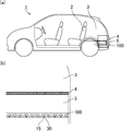
- a vehicle such as a car is a machine that has a power source such as an engine and can be moved by human operation, and generates various vibrations and noises.
- the sounds transmitted to the inside of the vehicle include not only the sounds emitted by the power source but also the sounds generated outside the vehicle such as road noise, tire pattern noise and wind noise generated when the vehicle travels. .
- these sounds When these sounds are transmitted to the inside of the vehicle, they cause discomfort to people, so sound insulation and sound absorbing members are used in the engine, engine room, interior, body, exhaust pipe, etc. Measures have been taken.
- the noise generated from the road surface during traveling such as tire pattern noise (in a frequency range of 500 to 3000 Hz and simply referred to as pattern noise) is less likely to be reflected and diffused around the lower part of the vehicle body, and the degree of sound intruding into the vehicle Is estimated to be high. Similar problems can occur with electric vehicles.
- noise that was conventionally diffused outside the vehicle is transmitted to a person riding the vehicle.
- these noises are likely to intrude from the bottom of the rear portion of the vehicle and the lower portion of the luggage room (under floor space) where the accommodation space is disposed. Since these noises include noise in the frequency range of 500 to 2000 Hz that people feel uncomfortable, it is required to take measures.
- Patent Document 1 discloses a flexible porous foam molded by foam molding, an introduction passage opened on one surface, and a hollow portion formed at the back of the introduction passage and having a cross-sectional area larger than that of the introduction passage.
- a sound absorbing member is disclosed which has a large number of resonance chambers.
- Patent Document 2 discloses a sound / sound insulation structure including a resin molded body having a plurality of independent blind cavities having openings on the front or back and a sound absorbing member, and having a specific 100 Hz to 10 kHz resonant sound absorption peak frequency. It is done.
- the Helmholtz resonance structure includes an introduction passage opened to the surface and a hollow portion connected to the outside through the introduction passage.
- the air in the introduction passage When the sound reaches the introduction passage of the Helmholtz resonance structure, the air in the introduction passage is pushed by the sound and tries to enter the hollow portion. At this time, since the air is an elastic body, the air in the hollow portion tries to push out the air in the introduction passage. That is, the air in the hollow portion functions as a spring. In this case, the movement of the air in the introduction passage can be expressed as a single vibration movement, and at this frequency, the sound reaching the introduction passage will be resonated and canceled. That is, sound is absorbed.
- the Helmholtz resonance structure can absorb sound of a predetermined frequency, but the sound absorption frequency depends on the volume of the hollow portion and the length and opening area of the introduction passage. Therefore, the sound absorption frequency can be adjusted by adjusting the volume of the hollow portion and the length and opening area of the introduction passage.
- the present invention is an invention made to solve the above-mentioned problems, and an object of the present invention is to provide a sound absorbing member having a sufficiently high sound absorption coefficient.
- the sound absorbing member according to the present invention is a sound absorbing member having a Helmholtz resonance structure including an introduction passage and a hollow portion connected to the outside through the introduction passage,
- the sound absorbing member includes a first layer and a second layer laminated to the first layer,
- the first layer has a first main surface and a second main surface opposite to the first main surface, and
- the second layer has a third main surface facing the second main surface and a fourth main surface opposite to the third main surface
- the first layer has a first through hole which penetrates the second main surface from the first main surface to form the introduction passage
- the second major surface includes a second major surface opening which is an end of the first through hole, and the other second major surface flat portion.
- the third main surface is composed of a third main surface opening that is an end of the hollow portion and the other third main surface flat portion,
- the opening area of the second main surface opening is smaller than the opening area of the third main surface opening,
- a first air layer is formed at least in part between the second major surface flat portion and the third major surface flat portion.
- the sound absorbing member of the present invention is a sound absorbing member in which a first layer forming an introduction passage and a second layer forming a hollow portion are laminated, and has a Helmholtz resonance structure. Therefore, sound of a predetermined frequency can be efficiently absorbed. Furthermore, in the sound absorbing member of the present invention, the first air layer is formed at least in part between the second main surface flat portion of the first layer and the third main surface flat portion of the second layer. . When the sound absorbing member has such a structure, the sound absorption coefficient is improved.
- the second main surface flat portion and the third main surface flat portion may be in contact with each other. Even if part of the second main surface flat portion and the third main surface flat portion are in contact with each other, the first air layer may be formed on a portion between the second main surface flat portion and the third main surface flat portion. If is formed, the sound absorption coefficient is improved.
- At least one of the second main surface flat portion and the third main surface flat portion has a curve or an undulation, and the second main surface flat portion and the third main surface flat portion have a part It may be in contact.
- the first air layer can be formed, and the sound absorption coefficient can be improved.
- the bottom surface of the hollow portion may be in the second layer.
- the second layer has the non-penetrating hole forming the hollow portion.
- the sound absorbing member having such a structure can be manufactured by laminating the first layer and the second layer.
- the third layer having a fifth main surface facing the fourth main surface and a sixth main surface opposite to the fifth main surface is laminated under the second layer.
- the second layer has a second through hole penetrating the fourth main surface from the third main surface to form a side surface of the hollow portion, and the fifth main surface is the The bottom surface of the hollow portion may be formed.
- a through hole that is the side surface of the hollow portion is formed in one layer, and a layer to be the bottom of the hollow portion is stacked thereunder to form a hollow portion.
- the formed sound absorber can be manufactured efficiently. That is, the sound absorbing member having such a structure has high manufacturing efficiency.
- the fourth main surface includes the fourth main surface opening that is an end of the second through hole and the other fourth main surface flat portion, and the fourth main surface is It is desirable that a second air layer be formed at least in part between the flat portion and the fifth main surface. In addition to the first air layer, if the second air layer is present at least in part between the fourth main surface flat portion of the second layer and the fifth main surface of the third layer, the sound absorption efficiency is further improved. .
- the fourth main surface flat portion and the fifth main surface may be in contact with each other. Even if the fourth major surface flat portion and the fifth major surface are in contact with each other, the second air layer is formed on a portion between the fourth major surface flat portion and the fifth major surface. Then, the sound absorption coefficient is improved.
- At least one of the fourth main surface flat portion and the fifth main surface has a curve or an undulation, and the fourth main surface flat portion and the fifth main surface are partially in contact with each other. It is also good.
- the second air layer can be formed, and the sound absorption coefficient can be improved.
- the first main surface includes a first main surface opening that is an end of the first through hole and the other first main surface flat portion, and the first main surface is It is desirable that a fiber layer be further formed on the flat portion.
- the sound absorbing member has a Helmholtz resonance structure, it can absorb sound in a predetermined frequency range, but the width of the frequency range that can absorb sound is not wide, and in particular, it is difficult to sufficiently absorb sound in a high frequency range of 2000 Hz or more. .
- the fiber layer is formed, sound in a high frequency region of 2000 Hz or more can be absorbed.
- the sound absorbing member of the present invention is desirably made of resin and / or fibrous material.
- the resin is preferably an elastomer such as a foamed resin or rubber.
- the sound absorbing member is made of resin, weight reduction can be easily achieved, which is particularly desirable as a component for a vehicle.
- the resin is a foamed resin, the weight thereof can be made lighter, which can contribute to the improvement of the fuel efficiency when it is used as a component for a vehicle.
- a composite material of resin and fiber may be used. As a method of compounding, resin and fiber may be mixed, resin and fiber may be combined in a block shape, and a plate of resin and fiber may be laminated.
- the parts for vehicles of the present invention are characterized by including the sound absorbing member of the present invention. Since the sound absorbing member of the present invention is excellent in sound absorbing performance, it is excellent as a component for a vehicle. As parts for vehicles provided with the sound absorption member of the present invention, a raising member, a partition member, a luggage box, etc. are mentioned.
- An automobile according to the present invention is characterized in that the introduction passage of the sound absorbing member according to the present invention is disposed in the direction of the road surface.
- FIG. 1 is a cross-sectional view schematically showing an example of the sound absorbing member of the present invention.
- FIG. 2 is a cross-sectional view schematically showing an example of the sound absorbing member of the present invention.
- FIG. 3 is a cross-sectional view schematically showing an example of the sound absorbing member of the present invention.
- FIG. 4 is a cross-sectional view schematically showing an example of the sound absorbing member of the present invention.
- FIG. 5 is a cross-sectional view schematically showing an example of the sound absorbing member of the present invention.
- FIG. 6 is a cross-sectional view schematically showing an example of the sound absorbing member of the present invention.
- FIG. 7 is a cross-sectional view schematically showing an example of the sound absorbing member of the present invention.
- FIG. 8 is a cross-sectional view schematically showing an example of the sound absorbing member of the present invention.
- FIG. 9 is a cross-sectional view schematically showing an example of the sound absorbing member of the present invention.
- Fig.10 (a) is explanatory drawing which shows typically an example of the site
- FIG.10 (b) is partial expansion of the area
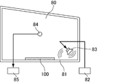
- FIG. 11 is an explanatory view schematically showing a reverberation chamber method sound absorption coefficient with respect to the sound absorption member.
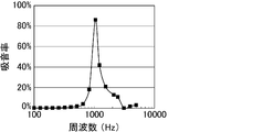
- FIG. 12 is a graph showing the results of a reverberation chamber method sound absorption coefficient test of the sound absorbing member according to the first embodiment of the present invention.
- FIG.10 (a) is explanatory drawing which shows typically an example of the site
- FIG.10 (b) is partial expansion of the area
- FIG. 13 is a graph showing the results of a reverberation chamber method sound absorption coefficient test of a sound absorbing member according to a second embodiment of the present invention.
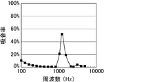
- FIG. 14 is a graph showing the results of a reverberation chamber method sound absorption coefficient test of a sound absorbing member according to Comparative Example 1 of the present invention.
- the sound absorbing member according to the present invention is a sound absorbing member having a Helmholtz resonance structure including an introduction passage and a hollow portion connected to the outside through the introduction passage,
- the sound absorbing member includes a first layer and a second layer laminated to the first layer,
- the first layer has a first main surface and a second main surface opposite to the first main surface, and
- the second layer has a third main surface facing the second main surface and a fourth main surface opposite to the third main surface
- the first layer has a first through hole which penetrates the second main surface from the first main surface to form the introduction passage
- the second major surface includes a second major surface opening which is an end of the first through hole, and the other second major surface flat portion.
- the third main surface is composed of a third main surface opening that is an end of the hollow portion and the other third main surface flat portion,
- the opening area of the second main surface opening is smaller than the opening area of the third main surface opening,
- a first air layer is formed at least in part between the second major surface flat portion and the third major surface flat portion.
- the sound absorbing member of the present invention is a sound absorbing member in which a first layer forming an introduction passage and a second layer forming a hollow portion are laminated, and has a Helmholtz resonance structure. Therefore, sound of a predetermined frequency can be efficiently absorbed. Furthermore, in the sound absorbing member of the present invention, the first air layer is formed at least in part between the second main surface flat portion of the first layer and the third main surface flat portion of the second layer. . When the sound absorbing member has such a structure, the sound absorption coefficient is improved.
- the first air layer may or may not be connected to the hollow portion, but it is more desirable to be connected to the hollow portion.
- the sound absorption coefficient is improved.
- the second major surface flat portion and the third major surface flat portion may be in contact with each other. Even if part of the second main surface flat portion and the third main surface flat portion are in contact with each other, the first air layer may be formed on a portion between the second main surface flat portion and the third main surface flat portion. If is formed, the sound absorption coefficient is improved.
- a spacer may or may not be provided between the second main surface flat portion and the third main surface flat portion in order to form the first air layer.
- the first air layer can be reliably formed on the sound absorbing member of the present invention.
- the absence of the spacer is advantageous because the spring mass effect is not diminished by the spacer.
- the sound absorbing member of the present invention preferably has a total thickness of 10 to 120 mm. More preferably, the thickness of the sound absorbing member is 20 to 100 mm. When the thickness of the sound absorbing member is less than 10 mm, it becomes difficult to form a Helmholtz resonance structure. When the thickness of the sound absorbing member exceeds 120 mm, the sound absorbing member becomes too large, and it becomes difficult to arrange in the desired space.
- the equivalent circle diameter of the opening of the introduction passage (first through hole) is preferably 1 to 30 mm, and more preferably 3 to 25 mm.
- the length of the introduction passage (first through hole) is preferably 1 to 20 mm, and more preferably 3 to 15 mm.
- the volume of the hollow portion is preferably 24 to 329,860 mm 3 , and more preferably 257 to 246,766 mm 3 .
- the sound absorbing member may be composed of two layers of the first layer and the second layer, or may be composed of three layers of the first layer, the second layer and the third layer.
- the case where a sound absorption member consists of two layers, and the case where it consists of the case where a sound absorption member consists of three are divided and demonstrated.
- the sound absorbing member of the present invention is composed of two layers.
- the bottom surface of the hollow portion is in the second layer. That is, in the sound absorbing member of the present invention, the second layer has the non-through hole forming the hollow portion.
- the sound absorbing member of the present invention having a Helmholtz resonance structure can be manufactured by laminating the first layer and the second layer.
- first and second layers as long as the first air layer is formed between the second main surface flat portion of the first layer and the third main surface flat portion of the second layer, It does not matter how they are stacked.
- an adhesive layer may be formed on a portion between the second major surface flat portion and the third major surface flat portion, and the first layer and the second layer may be stacked. Under the present circumstances, you may adhere
- the fitting portion male portion and female portion
- the first through hole is desirably cylindrical, and the cross-sectional shape in the direction perpendicular to the longitudinal direction is preferably a perfect circle.
- the introduction passage has a cylindrical shape. It is advantageous that the introduction passage has a cylindrical shape because the sound absorption characteristics do not have anisotropy.
- the diameter of the bottom surface in the case where the first through hole is cylindrical is preferably 1 to 30 mm. That is, in the sound absorbing member of the present invention, the inner diameter of the introduction passage is preferably 1 to 30 mm.
- the shape of the first through hole is not cylindrical, the diameter of the first through hole is determined as the equivalent circle diameter.
- the equivalent circle diameter is the diameter when the cross-sectional area of the first through hole when cutting the first through hole in the direction perpendicular to the length direction is replaced with a true circle of the same area.
- the diameter may be used as the equivalent circle diameter.
- the arrangement pattern of the first through holes provided in the first layer is a square arrangement in which the first through holes are arranged at the apexes of the squares in a plane in which the squares are continuously arranged vertically and horizontally. It may be a staggered arrangement in which the first through holes are arranged at the apexes of triangles in a plane in which regular triangles are arranged continuously in the vertical and horizontal directions. Among these, a staggered arrangement is desirable. When the arrangement pattern of the first through holes is a staggered arrangement, the adjacent first through holes are likely to be equally spaced, so that the sound absorbing effect is improved. In addition, the strength as the plate material of the first layer can be obtained.
- the plate material constituting the first layer is preferably made of resin.
- the resin is preferably an elastomer such as a foamed resin or rubber. It is particularly desirable as a component for a vehicle because weight reduction can be easily achieved when the plate material constituting the first layer is made of resin. In addition, when the resin is a foamed resin, the weight thereof can be made lighter, which can contribute to the improvement of the fuel efficiency when it is used as a component for a vehicle.
- the plate material constituting the first layer may be a composite material of resin and fiber. As a method of compounding, resin and fiber may be mixed, resin and fiber may be combined in a block shape, and a plate of resin and fiber may be laminated.
- the resin be any of a foamed resin composed of expandable resin particles (beads), a foamed resin having cells, a thermoplastic resin, and a thermosetting resin. It is preferable that the material of the resin has a density of 0.01 to 1 g / cm 3 , and more preferably, the density of the resin is 0.02 to 0.1 g / cm 3 .
- the density of the resin indicates the density of the foamed resin that has been foam-molded. If the density of the resin is within the above range, it is easy to obtain the strength necessary for the sound absorbing member.
- the resin is more preferably a foamed resin comprising expandable resin particles (beads).
- the resin is a foamed resin composed of expandable resin particles (beads)
- the weight of the sound absorbing member can be reduced while maintaining the strength, which can contribute to the improvement of fuel efficiency when used for parts for vehicles .
- the foamed resin is obtained by foaming and molding expandable resin particles.
- the expandable resin particles (beads) used as the plate material constituting the first layer are particles containing a foaming agent inside the resin particles, and known materials are suitably used.
- the resin component constituting the expandable resin particles include olefin resins such as polyethylene and polypropylene, and styrene resins such as polystyrene.
- a styrene resin a copolymer obtained by copolymerizing a styrene homopolymer, styrene, and a monomer (or its derivative) copolymerizable with styrene is mentioned.
- the styrene copolymer may be any of a block copolymer, a random copolymer, and a graft copolymer.
- the blowing agent include hydrocarbons such as propane, butane and pentane.
- the expandable resin particles used as a plate material constituting the first layer may be, if necessary, a flame retardant, a flame retardant aid, a processing aid, a filler, an antioxidant, light resistance
- Known additives such as a sex stabilizer, an antistatic agent and a colorant may be added.
- a sex stabilizer As an example of use of an additive, if a black thing is used for a coloring agent, a stain will become inconspicuous.
- Flame retardants include hydrated metal flame retardants such as aluminum hydroxide and magnesium hydroxide, phosphoric acid flame retardants such as red phosphorus and ammonium phosphate, tetrabromobisphenol A (TABB), brominated polystyrene, chlorinated paraffin And halogen-based flame retardants, ammonium carbonate, nitrogen-based flame retardants such as melamine cyanurate, and the like.
- phosphoric acid flame retardants such as red phosphorus and ammonium phosphate, tetrabromobisphenol A (TABB), brominated polystyrene, chlorinated paraffin And halogen-based flame retardants, ammonium carbonate, nitrogen-based flame retardants such as melamine cyanurate, and the like.
- TABB tetrabromobisphenol A
- brominated polystyrene chlorinated paraffin And halogen-based flame retardants
- ammonium carbonate such as melamine cyanurate
- antioxidant examples include alkylphenols, alkylene bisphenols, alkylphenol thioethers, ⁇ , ⁇ -thiopropionic acid esters, organic phosphites and phenol-nickel complexes.
- light fastness stabilizer examples include benzotriazole-based UV absorbers and hindered amine-based stabilizers.
- antistatic agent examples include low molecular weight antistatic agents such as fatty acid ester compounds, aliphatic ethanolamine compounds and aliphatic ethanolamide compounds, and high molecular weight antistatic agents.
- a coloring agent a dye, a pigment, etc. are mentioned.
- the average particle diameter of the expandable resin particles used as the plate material constituting the first layer is preferably 300 ⁇ m to 2400 ⁇ m, and more preferably 800 ⁇ m to 2000 ⁇ m.
- the expansion ratio of the expandable resin particles is desirably 10 to 60 times. By setting the expansion ratio to 10 to 60 times, the density of the resin can be easily adjusted to the range of 0.02 to 0.1 g / cm 3 . On the other hand, if the expansion ratio is less than 10 times, the sound absorbing member may be too hard or too heavy. When the expansion ratio exceeds 60 times, the strength of the sound absorbing member may be insufficient.
- polyurethane or the like can be used as the foamed resin used as the plate material constituting the first layer.
- a foaming agent and the like By mixing polyurethane as a main ingredient, a foaming agent and the like, and foaming and forming the mixture, a foamed resin having cells can be obtained, whereby a plate material can be manufactured.
- the resin used as the plate material constituting the first layer may be a thermoplastic resin or a thermosetting resin.
- a thermoplastic resin used as a plate material constituting the first layer polypropylene resin, polyethylene resin, polyester resin (such as nylon 6-6), polystyrene resin, etc. can be used.
- a sound absorbing member can be manufactured by molding a thermoplastic resin as a resin pellet, heating the resin pellet, and performing a molding process such as injection molding and extrusion molding.
- epoxy resin, phenol resin, melamine resin, urea resin, polyurethane, polyurea, polyamide, polyacrylamide, etc. may be used as the thermosetting resin used as the plate material constituting the first layer. it can.
- the sound absorbing member can be manufactured by preheating the thermosetting resin, placing it in a mold, pressurizing it, raising the temperature of the mold and curing it.
- the plate material constituting the first layer in addition to the resin, a material such as an inorganic material or a metal material may be used.
- the thickness of the plate constituting the first layer is preferably 1 to 20 mm.
- the thickness of the plate is the length of the first through hole and the length of the introduction passage. That is, the length of the first through hole is preferably 1 to 20 mm. Further, the length of the introduction passage is also preferably 1 to 20 mm.
- the first main surface is composed of the first main surface opening which is the end of the first through hole and the other first main surface flat portion, but the first main surface is flat.
- a fiber layer is further formed on the part.
- the material constituting the fiber layer is preferably selected from natural fibers, synthetic resin fibers, and inorganic fibers.
- Natural fibers include vegetable fibers, animal fibers and mineral fibers.
- synthetic resin fibers include polyamide resins (nylon etc.), polyester resins (polyethylene terephthalate (PET), polyethylene naphthalate (PEN) etc.), acrylic resins, polyvinyl alcohol resins, polyolefin resins (polyethylene, polypropylene etc.) etc. It can be mentioned.
- As the inorganic fibers alumina fibers, silica fibers, silica-alumina fibers, glass fibers, carbon fibers, potassium titanate fibers, rock wool and the like can be mentioned.
- the fiber layer may be formed as a felt or non-woven fabric.
- the thickness of the fiber layer is preferably 1 to 20 mm.
- air vibration occurs in the space, and sound in a high frequency region can be absorbed.
- the first major surface flat portion and the fiber layer may or may not be bonded by an adhesive layer.
- the second layer is a plate having a non-through hole, and is stacked with the first layer.
- the non-through hole of the second layer is connected to the first through hole of the first layer, ie, the introduction passage, so that the non-through hole is connected to the outside to form a Helmholtz resonance structure.
- the shape of the non-through hole provided in the second layer in the sound absorbing member of the present invention is preferably cylindrical, and the cross-sectional shape in the direction perpendicular to the longitudinal direction is preferably a perfect circle.
- the height is preferably 1 to 20 mm, and more preferably 3 to 15 mm.
- the diameter of the non-through hole is determined as a circle equivalent diameter.
- the equivalent circle diameter is a diameter when the cross-sectional area of the non-through hole when cutting the non-through hole in the direction perpendicular to the length direction is replaced with a true circle of the same area.
- the cross-sectional shape of the non-through hole is a perfect circle, the diameter may be used as the equivalent circle diameter.
- the arrangement pattern of non-through holes provided in the second layer may be a tetragonal arrangement in which non-through holes are disposed at the apexes of squares in a plane in which squares are continuously arranged vertically and horizontally. It may be a staggered arrangement in which non-through holes are arranged at the apexes of triangles in a plane in which regular triangles are arranged continuously in the vertical and horizontal directions. Among these, a staggered arrangement is desirable. When the arrangement pattern of the non-through holes is a staggered arrangement, the adjacent non-through holes are likely to be equally spaced, so that the sound absorbing effect is improved. In addition, the strength as the plate material of the second layer can be obtained.
- the positional relationship between the introduction passage and the non-through hole may be such that the non-through hole is connected to the outside through the introduction passage, and the center of the introduction passage and the non-through hole (perpendicular to the thickness direction The center in the cross-sectional shape when cutting in the same direction may or may not coincide.
- the non-through holes in the second layer are preferably formed by machining the plate material, and cutting with an end mill or processing with a hot wire is preferably used.
- a foamed resin comprising expandable resin particles (beads) as a plate material, a plate material having non-through holes can also be obtained by performing foam molding in a mold having protrusions corresponding to the shape of non-through holes. It can be made.
- the plate material constituting the second layer is desirably made of a resin and / or a fibrous material.
- the resin is preferably an elastomer such as a foamed resin or rubber. It is particularly desirable as a vehicle part because weight reduction can be easily achieved when the plate material constituting the second layer is made of resin. In addition, when the resin is a foamed resin, the weight thereof can be made lighter, which can contribute to the improvement of the fuel efficiency when it is used as a component for a vehicle.
- the plate material constituting the second layer may be a composite material of resin and fiber. As a method of compounding, resin and fiber may be mixed, resin and fiber may be combined in a block shape, and a plate of resin and fiber may be laminated.
- the resin be any of a foamed resin composed of expandable resin particles (beads), a foamed resin having cells, a thermoplastic resin, and a thermosetting resin. It is preferable that the material of the resin has a density of 0.01 to 1 g / cm 3 , and more preferably, the density of the resin is 0.02 to 0.1 g / cm 3 .
- the density of the resin indicates the density of the foamed resin that has been foam-molded. If the density of the resin is within the above range, it is easy to obtain the strength necessary for the sound absorbing member.
- the resin is more preferably a foamed resin comprising expandable resin particles (beads).
- the resin is a foamed resin composed of expandable resin particles (beads)
- the weight of the sound absorbing member can be reduced while maintaining the strength, which can contribute to the improvement of fuel efficiency when used for parts for vehicles .
- the foamed resin is obtained by foaming and molding expandable resin particles.
- a plate material which is a foamed resin comprising expandable resin particles (beads) does not have communicating pores.
- the expandable resin particles (beads) used as a plate material constituting the second layer are particles containing a foaming agent inside the resin particles, and known materials are suitably used.
- the resin component constituting the expandable resin particles include olefin resins such as polyethylene and polypropylene, and styrene resins such as polystyrene.
- a styrene resin a copolymer obtained by copolymerizing a styrene homopolymer, styrene, and a monomer (or its derivative) copolymerizable with styrene is mentioned.
- the styrene copolymer may be any of a block copolymer, a random copolymer, and a graft copolymer.
- the blowing agent include hydrocarbons such as propane, butane and pentane.
- the expandable resin particles used as the plate material constituting the second layer may be, if necessary, a flame retardant, a flame retardant aid, a processing aid, a filler, an antioxidant, light resistance
- Known additives such as a sex stabilizer, an antistatic agent and a colorant may be added.
- a black thing is used for a coloring agent, a stain will become inconspicuous.
- Flame retardants include hydrated metal flame retardants such as aluminum hydroxide and magnesium hydroxide, phosphoric acid flame retardants such as red phosphorus and ammonium phosphate, tetrabromobisphenol A (TABB), brominated polystyrene, chlorinated paraffin And halogen-based flame retardants, ammonium carbonate, nitrogen-based flame retardants such as melamine cyanurate, and the like.
- phosphoric acid flame retardants such as red phosphorus and ammonium phosphate, tetrabromobisphenol A (TABB), brominated polystyrene, chlorinated paraffin And halogen-based flame retardants, ammonium carbonate, nitrogen-based flame retardants such as melamine cyanurate, and the like.
- TABB tetrabromobisphenol A
- brominated polystyrene chlorinated paraffin And halogen-based flame retardants
- ammonium carbonate such as melamine cyanurate
- antioxidant examples include alkylphenols, alkylene bisphenols, alkylphenol thioethers, ⁇ , ⁇ -thiopropionic acid esters, organic phosphites and phenol-nickel complexes.
- light fastness stabilizer examples include benzotriazole-based UV absorbers and hindered amine-based stabilizers.
- antistatic agent examples include low molecular weight antistatic agents such as fatty acid ester compounds, aliphatic ethanolamine compounds and aliphatic ethanolamide compounds, and high molecular weight antistatic agents.
- a coloring agent a dye, a pigment, etc. are mentioned.
- the average particle diameter of the expandable resin particles used as a plate material constituting the second layer is preferably 300 ⁇ m to 2400 ⁇ m, and more preferably 800 ⁇ m to 2000 ⁇ m.
- the expansion ratio of the expandable resin particles is desirably 10 to 60 times. By setting the expansion ratio to 10 to 60 times, the density of the resin can be easily adjusted to the range of 0.02 to 0.1 g / cm 3 . On the other hand, if the expansion ratio is less than 10 times, the sound absorbing member may be too hard or too heavy. When the expansion ratio exceeds 60 times, the strength of the sound absorbing member may be insufficient.
- polyurethane or the like can be used as the foamed resin used as the plate material constituting the second layer.
- a foaming agent and the like By mixing polyurethane as a main ingredient, a foaming agent and the like, and foaming and forming the mixture, a foamed resin having cells can be obtained, whereby a plate material can be manufactured.
- the resin used as the plate material constituting the second layer may be a thermoplastic resin or a thermosetting resin.
- a thermoplastic resin used as a plate material constituting the second layer polypropylene resin, polyethylene resin, polyester resin (such as nylon 6-6), polystyrene resin, etc. can be used.
- a sound absorbing member can be manufactured by molding a thermoplastic resin as a resin pellet, heating the resin pellet, and performing a molding process such as injection molding and extrusion molding.
- epoxy resin, phenol resin, melamine resin, urea resin, polyurethane, polyurea, polyamide, polyacrylamide, etc. may be used as the thermosetting resin used as the plate material constituting the second layer. it can.
- the sound absorbing member can be manufactured by preheating the thermosetting resin, placing it in a mold, pressurizing it, raising the temperature of the mold and curing it.
- the fibers used as the plate material constituting the second layer are preferably organic fibers or inorganic fibers, and polyester, polyamide, acetate or the like can be used as the organic fibers.
- the inorganic fibers alumina, silica and mullite fibers are desirable. It is desirable to bond the fibers together with the binder into a felt.
- the plate material constituting the second layer in addition to the resin, a material such as an inorganic material or a metal material may be used.
- the thickness of the plate constituting the second layer is preferably 10 to 120 mm. In addition, it is further desirable that the distance be 20 to 100 mm.
- the first layer and the second layer may be bonded by an adhesive.
- the upper and lower layers may be connected by providing a female portion and a male portion in the upper and lower layer contact portions and fitting them together.
- FIG. 1 is a cross-sectional view schematically showing an example of the sound absorbing member of the present invention.
- FIG. 2 is a cross-sectional view schematically showing an example of the sound absorbing member of the present invention.
- FIG. 3 is a cross-sectional view schematically showing an example of the sound absorbing member of the present invention.
- FIG. 4 is a cross-sectional view schematically showing an example of the sound absorbing member of the present invention.
- FIG. 5 is a cross-sectional view schematically showing an example of the sound absorbing member of the present invention.
- the sound absorbing member of the present invention may be configured as shown in FIG. That is, the sound absorbing member 100 which is an example of the sound absorbing member of the present invention includes the first layer 10 and the second layer 20 laminated on the first layer 10.
- the first layer 10 has a first major surface 11 and a second major surface 12 opposite to the first major surface 11.
- the first layer 10 has a first through hole 15 which penetrates the second major surface 12 from the first major surface 11 to form an introduction passage.
- the second major surface 12 is composed of a second major surface opening 12 a which is an end portion of the first through hole 15, and the other second major surface flat portion 12 b.
- the second layer 20 has a third major surface 21 facing the second major surface 12 and a fourth major surface 22 opposite to the third major surface 21.
- the non-through holes 30a are formed on the third main surface 21 side.
- the third major surface 21 is composed of a third major surface opening 21a which is an end portion of the non-through hole 30a, and the other third major surface flat portion 21b.
- the opening area of the second main surface opening 12a is smaller than the opening area of the third main surface opening 21a.
- the first layer 10 and the second layer 20 are partially bonded by the adhesive layer 40, and the non-through holes 30a form the hollow portion 30, and the hollow portion 30 is formed.
- the bottom surface 31 of the is to be in the second layer 20.
- a first air layer 50 is formed between the second major surface flat portion 12 b and the third major surface flat portion 21 b.
- the first air layer 50 is connected to the hollow portion 30.
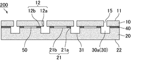
- the sound absorbing member of the present invention may be configured as shown in FIG. That is, the sound absorbing member 200 which is an example of the sound absorbing member of the present invention includes the first layer 10 and the second layer 20 laminated on the first layer 10.
- the first layer 10 has a first major surface 11 and a second major surface 12 opposite to the first major surface 11.
- the first layer 10 has a first through hole 15 which penetrates the second major surface 12 from the first major surface 11 to form an introduction passage.
- the second major surface 12 is composed of a second major surface opening 12 a which is an end portion of the first through hole 15, and the other second major surface flat portion 12 b.
- the second layer 20 has a third major surface 21 facing the second major surface 12 and a fourth major surface 22 opposite to the third major surface 21.
- the non-through holes 30a are formed on the third main surface 21 side.
- the third major surface 21 is composed of a third major surface opening 21a which is an end portion of the non-through hole 30a, and the other third major surface flat portion 21b.
- the opening area of the second main surface opening 12a is smaller than the opening area of the third main surface opening 21a.
- a part of the first layer 10 and the second layer 20 is adhered by the adhesive layer 40, and the non-through hole 30a forms the hollow portion 30, and the hollow portion 30 is formed.
- the bottom surface 31 of the is to be in the second layer 20.
- a first air layer 50 is formed between the second major surface flat portion 12 b and the third major surface flat portion 21 b.
- the first air layer 50 is not connected to the hollow portion 30.
- the sound absorbing member of the present invention may be configured as shown in FIG. That is, the sound absorbing member 300 which is an example of the sound absorbing member of the present invention includes the first layer 10 and the second layer 20 laminated on the first layer 10.
- the first layer 10 has a first major surface 11 and a second major surface 12 opposite to the first major surface 11.
- the first layer 10 has a first through hole 15 which penetrates the second major surface 12 from the first major surface 11 to form an introduction passage.
- the second major surface 12 is composed of a second major surface opening 12 a which is an end portion of the first through hole 15, and the other second major surface flat portion 12 b.
- the second layer 20 has a third major surface 21 facing the second major surface 12 and a fourth major surface 22 opposite to the third major surface 21.
- the non-through holes 30a are formed on the third main surface 21 side.
- the third major surface 21 is composed of a third major surface opening 21a which is an end portion of the non-through hole 30a, and the other third major surface flat portion 21b.
- the opening area of the second main surface opening 12a is smaller than the opening area of the third main surface opening 21a.
- the edge portion of the second major surface flat portion 12b and the edge portion of the third major surface flat portion 21b are bonded by the adhesive layer 40.
- the non-through hole 30 a forms the hollow portion 30, and the bottom surface 31 of the hollow portion 30 is in the second layer 20.
- a first air layer 50 is formed between the second major surface flat portion 12 b and the third major surface flat portion 21 b, and the first air layer 50 is connected to the hollow portion 30. .
- the sound absorption coefficient is improved by the spring mass effect.
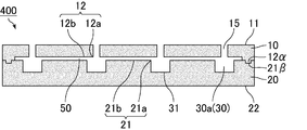
- the sound absorbing member of the present invention may be configured as shown in FIG. That is, the sound absorbing member 400 which is an example of the sound absorbing member of the present invention includes the first layer 10 and the second layer 20 laminated on the first layer 10.
- the first layer 10 has a first major surface 11 and a second major surface 12 opposite to the first major surface 11.
- the first layer 10 has a first through hole 15 which penetrates the second major surface 12 from the first major surface 11 to form an introduction passage.
- the second major surface 12 is composed of a second major surface opening 12 a which is an end portion of the first through hole 15, and the other second major surface flat portion 12 b.
- the second layer 20 has a third major surface 21 facing the second major surface 12 and a fourth major surface 22 opposite to the third major surface 21.
- the non-through holes 30a are formed on the third main surface 21 side.
- the third major surface 21 is composed of a third major surface opening 21a which is an end portion of the non-through hole 30a, and the other third major surface flat portion 21b.
- the opening area of the second main surface opening 12a is smaller than the opening area of the third main surface opening 21a.
- the male portion 12 ⁇ is formed in the second major surface flat portion 12b
- the female portion 21 ⁇ is formed in the third major surface flat portion 21b.
- the layer 10 and the second layer 20 are connected.
- the non-through hole 30a forms the hollow portion 30, and the bottom surface 31 of the hollow portion 30 is in the second layer 20.
- a first air layer 50 is formed between the second major surface flat portion 12 b and the third major surface flat portion 21 b.
- the first air layer 50 is connected to the hollow portion 30.
- the sound absorbing member of the present invention may be configured as shown in FIG. That is, the sound absorbing member 500 which is an example of the sound absorbing member of the present invention includes the first layer 10 and the second layer 20 laminated on the first layer 10.
- the first layer 10 has a first major surface 11 and a second major surface 12 opposite to the first major surface 11.
- the first layer 10 has a first through hole 15 which penetrates the second major surface 12 from the first major surface 11 to form an introduction passage.
- the second major surface 12 is composed of a second major surface opening 12 a which is an end portion of the first through hole 15, and the other second major surface flat portion 12 b.
- the second layer 20 has a third major surface 21 facing the second major surface 12 and a fourth major surface 22 opposite to the third major surface 21.
- the non-through holes 30a are formed on the third main surface 21 side.
- the third major surface 21 is composed of a third major surface opening 21a which is an end portion of the non-through hole 30a, and the other third major surface flat portion 21b.
- the opening area of the second main surface opening 12a is smaller than the opening area of the third main surface opening 21a.
- the second main surface flat portion 12b and the third main surface flat portion 21b are bonded by an adhesive at the end.
- the non-through holes 30a form the hollow portion 30, and the bottom surface 31 of the hollow portion 30 is in the second layer 20.
- the first layer 10 is curved to be convex upward
- the first air layer 50 is formed between the second major surface flat portion 12 b and the third major surface flat portion 21 b. . That is, the second major surface flat portion 12b is curved so as to be convex upward.
- the first air layer 50 is connected to the hollow portion 30. By forming the first air layer 50, the sound absorption coefficient is improved by the spring mass effect.
- the sound absorbing member of the present invention can be manufactured by laminating a first layer in which a first through hole is provided in a plate material and a second layer in which a hollow portion is provided.
- the method for producing the sound absorbing member of the present invention is Producing an upper layer which is a plate material having a columnar first through hole serving as an introduction passage; Producing a second layer which is a plate material having a hollow portion; And laminating the first layer and the second layer such that a first air layer is formed between the second major surface flat portion of the first layer and the third major surface flat portion of the second layer.
- a plate material of a predetermined thickness made of a material such as a resin that can be used as a plate material is prepared.
- the first layer can be produced by forming the first through hole with a means such as punching, drill or laser for a plate material having no through hole.
- a foamed resin comprising expandable resin particles (beads) as a plate material
- the plate is also provided with a protrusion for forming the first through hole in the mold to foam the expandable resin particles.
- a first layer provided with a first through hole can be manufactured.
- a plate material of a predetermined thickness made of a material such as a resin that can be used as a plate material is prepared.
- the second layer can be manufactured by forming a non-through hole which becomes a hollow portion by the middle of the thickness direction of a plate material having no through hole.
- the diameter of the non-through hole is made larger than the diameter of the first through hole.
- the non-through holes are preferably formed by machining, and cutting with an end mill or processing with a hot wire is preferably used.
- a plate material having non-through holes can also be obtained by performing foam molding in a mold having protrusions corresponding to the shape of non-through holes. It can be made.
- the fitting portion male portion or the male portion or the second layer
- female part may be formed.
- a sheet-like adhesive is prepared in accordance with the shape and position of the non-through holes (hollow part) of the second layer. Do. At this time, the sheet-like adhesive layer is processed so that the first air layer is formed between the second main surface flat portion of the first layer and the third main surface flat portion of the second layer. .
- the first layer and the second layer can be bonded by the adhesive layer by exerting the adhesive force of the adhesive by sandwiching the first layer and the second layer.
- the Helmholtz resonance structure is formed by aligning the positions of the first through holes of the first layer and the hollow portions (non-through holes) of the second layer. Let's do it.
- An adhesive is applied according to the shape and position of the non-through holes (hollow part) of the second layer, and the first layer and the second layer are laminated to exert the adhesive force of the adhesive, thereby forming the first layer
- the second layer can be adhered by an adhesive layer.
- the conditions for exerting the adhesive strength of the adhesive conditions in accordance with the adhesive characteristics of the adhesive may be used.
- the sound absorbing member of the present invention manufactures the sound absorbing member of the present invention having a Helmholtz resonance structure by laminating the first layer forming the introduction passage, and the second layer and the third layer forming the hollow portion. can do.
- first and second layers as long as the first air layer is formed between the second main surface flat portion of the first layer and the third main surface flat portion of the second layer, It does not matter how they are stacked.
- an adhesive layer may be formed on a portion between the second major surface flat portion and the third major surface flat portion, and the first layer and the second layer may be stacked. Under the present circumstances, you may adhere
- the fitting portion male portion and female portion
- the first through hole is desirably cylindrical, and the cross-sectional shape in the direction perpendicular to the longitudinal direction is preferably a perfect circle.
- the introduction passage has a cylindrical shape. It is advantageous that the introduction passage has a cylindrical shape because the sound absorption characteristics do not have anisotropy.
- the diameter of the bottom surface in the case where the first through hole is cylindrical is preferably 1 to 30 mm. That is, in the sound absorbing member of the present invention, the inner diameter of the introduction passage is preferably 1 to 30 mm.
- the shape of the first through hole is not cylindrical, the diameter of the first through hole is determined as the equivalent circle diameter.
- the equivalent circle diameter is the diameter when the cross-sectional area of the first through hole when cutting the first through hole in the direction perpendicular to the length direction is replaced with a true circle of the same area.
- the diameter may be used as the equivalent circle diameter.
- the arrangement pattern of the first through holes provided in the first layer is a square arrangement in which the first through holes are arranged at the apexes of the squares in a plane in which the squares are continuously arranged vertically and horizontally. It may be a staggered arrangement in which the first through holes are arranged at the apexes of triangles in a plane in which regular triangles are arranged continuously in the vertical and horizontal directions. Among these, a staggered arrangement is desirable. When the arrangement pattern of the first through holes is a staggered arrangement, the adjacent first through holes are likely to be equally spaced, so that the sound absorbing effect is improved. In addition, the strength as the plate material of the first layer can be obtained.
- the plate material constituting the first layer is preferably made of resin.
- the resin is preferably an elastomer such as a foamed resin or rubber. It is particularly desirable as a component for a vehicle because weight reduction can be easily achieved when the plate material constituting the first layer is made of resin. In addition, when the resin is a foamed resin, the weight thereof can be made lighter, which can contribute to the improvement of the fuel efficiency when it is used as a component for a vehicle.
- the plate material constituting the first layer may be a composite material of resin and fiber. As a method of compounding, resin and fiber may be mixed, resin and fiber may be combined in a block shape, and a plate of resin and fiber may be laminated.
- the resin be any of a foamed resin composed of expandable resin particles (beads), a foamed resin having cells, a thermoplastic resin, and a thermosetting resin. It is preferable that the material of the resin has a density of 0.01 to 1 g / cm 3 , and more preferably, the density of the resin is 0.02 to 0.1 g / cm 3 .
- the density of the resin indicates the density of the foamed resin that has been foam-molded. If the density of the resin is within the above range, it is easy to obtain the strength necessary for the sound absorbing member.
- the resin is more preferably a foamed resin comprising expandable resin particles (beads).
- the resin is a foamed resin composed of expandable resin particles (beads)
- the weight of the sound absorbing member can be reduced while maintaining the strength, which can contribute to the improvement of fuel efficiency when used for parts for vehicles .
- the foamed resin is obtained by foaming and molding expandable resin particles.
- the expandable resin particles (beads) used as the plate material constituting the first layer are particles containing a foaming agent inside the resin particles, and known materials are suitably used.
- the resin component constituting the expandable resin particles include olefin resins such as polyethylene and polypropylene, and styrene resins such as polystyrene.
- a styrene resin a copolymer obtained by copolymerizing a styrene homopolymer, styrene, and a monomer (or its derivative) copolymerizable with styrene is mentioned.
- the styrene copolymer may be any of a block copolymer, a random copolymer, and a graft copolymer.
- the blowing agent include hydrocarbons such as propane, butane and pentane.
- the expandable resin particles used as a plate material constituting the first layer may be, if necessary, a flame retardant, a flame retardant aid, a processing aid, a filler, an antioxidant, light resistance
- Known additives such as a sex stabilizer, an antistatic agent and a colorant may be added.
- a sex stabilizer As an example of use of an additive, if a black thing is used for a coloring agent, a stain will become inconspicuous.
- Flame retardants include hydrated metal flame retardants such as aluminum hydroxide and magnesium hydroxide, phosphoric acid flame retardants such as red phosphorus and ammonium phosphate, tetrabromobisphenol A (TABB), brominated polystyrene, chlorinated paraffin And halogen-based flame retardants, ammonium carbonate, nitrogen-based flame retardants such as melamine cyanurate, and the like.
- phosphoric acid flame retardants such as red phosphorus and ammonium phosphate, tetrabromobisphenol A (TABB), brominated polystyrene, chlorinated paraffin And halogen-based flame retardants, ammonium carbonate, nitrogen-based flame retardants such as melamine cyanurate, and the like.
- TABB tetrabromobisphenol A
- brominated polystyrene chlorinated paraffin And halogen-based flame retardants
- ammonium carbonate such as melamine cyanurate
- antioxidant examples include alkylphenols, alkylene bisphenols, alkylphenol thioethers, ⁇ , ⁇ -thiopropionic acid esters, organic phosphites and phenol-nickel complexes.
- light fastness stabilizer examples include benzotriazole-based UV absorbers and hindered amine-based stabilizers.
- antistatic agent examples include low molecular weight antistatic agents such as fatty acid ester compounds, aliphatic ethanolamine compounds and aliphatic ethanolamide compounds, and high molecular weight antistatic agents.
- a coloring agent a dye, a pigment, etc. are mentioned.
- the average particle diameter of the expandable resin particles used as the plate material constituting the first layer is preferably 300 ⁇ m to 2400 ⁇ m, and more preferably 800 ⁇ m to 2000 ⁇ m.
- the expansion ratio of the expandable resin particles is desirably 10 to 60 times. By setting the expansion ratio to 10 to 60 times, the density of the resin can be easily adjusted to the range of 0.02 to 0.1 g / cm 3 . On the other hand, if the expansion ratio is less than 10 times, the sound absorbing member may be too hard or too heavy. When the expansion ratio exceeds 60 times, the strength of the sound absorbing member may be insufficient.
- polyurethane or the like can be used as the foamed resin used as the plate material constituting the first layer.
- a foaming agent and the like By mixing polyurethane as a main ingredient, a foaming agent and the like, and foaming and forming the mixture, a foamed resin having cells can be obtained, whereby a plate material can be manufactured.
- the resin used as the plate material constituting the first layer may be a thermoplastic resin or a thermosetting resin.
- a thermoplastic resin used as a plate material constituting the first layer polypropylene resin, polyethylene resin, polyester resin (such as nylon 6-6), polystyrene resin, etc. can be used.
- a sound absorbing member can be manufactured by molding a thermoplastic resin as a resin pellet, heating the resin pellet, and performing a molding process such as injection molding and extrusion molding.
- epoxy resin, phenol resin, melamine resin, urea resin, polyurethane, polyurea, polyamide, polyacrylamide, etc. may be used as the thermosetting resin used as the plate material constituting the first layer. it can.
- the sound absorbing member can be manufactured by preheating the thermosetting resin, placing it in a mold, pressurizing it, raising the temperature of the mold and curing it.
- the plate material constituting the first layer in addition to the resin, a material such as an inorganic material or a metal material may be used.
- the thickness of the plate constituting the first layer is preferably 1 to 20 mm.
- the thickness of the plate is the length of the first through hole and the length of the introduction passage. That is, the length of the first through hole is preferably 1 to 20 mm. Further, the length of the introduction passage is also preferably 1 to 20 mm.
- the first main surface is composed of the first main surface opening which is the end of the first through hole and the other first main surface flat portion, but the first main surface is flat.
- a fiber layer is further formed on the part.
- the material constituting the fiber layer is preferably selected from natural fibers, synthetic resin fibers, and inorganic fibers.
- Natural fibers include vegetable fibers, animal fibers and mineral fibers.
- synthetic resin fibers include polyamide resins (nylon etc.), polyester resins (polyethylene terephthalate (PET), polyethylene naphthalate (PEN) etc.), acrylic resins, polyvinyl alcohol resins, polyolefin resins (polyethylene, polypropylene etc.) etc. It can be mentioned.
- As the inorganic fibers alumina fibers, silica fibers, silica-alumina fibers, glass fibers, carbon fibers, potassium titanate fibers, rock wool and the like can be mentioned.
- the fiber layer may be formed as a felt or non-woven fabric.
- the thickness of the fiber layer is preferably 1 to 20 mm.
- air vibration occurs in the space, and sound in a high frequency region can be absorbed.
- the first major surface flat portion and the fiber layer may or may not be bonded by an adhesive layer.
- the second layer is a plate material provided with a columnar second through hole having a larger opening diameter than the first through hole
- the third layer is a plate material not provided with the through hole May be A hollow portion can be formed by laminating the second layer and the third layer.
- the second layer is made of a plate material, and the plate material is provided with a second through hole.
- the second through hole is in a columnar shape, and is a portion having a columnar space only with air. It is preferable that the diameter of the through hole is constant from the inlet side to the outlet side in the thickness direction of the plate material. That is, it is preferable not to include a form in which gas passes in the thickness direction but the other side can not be seen (does not penetrate) in top view in the thickness direction, such as communicating pores in a porous material.
- the second through hole is preferably a through hole formed by machining a plate material having no through hole, and punching by a punching, a drill, a laser or the like is suitably used.
- the second through hole provided in the second layer is preferably cylindrical, and the cross-sectional shape in the direction perpendicular to the longitudinal direction is preferably a perfect circle.
- the hollow portion has a cylindrical shape. It is advantageous that the hollow portion has a cylindrical shape because the sound absorption characteristics do not have anisotropy.
- the diameter (opening diameter) of the bottom surface when the second through hole is cylindrical is preferably 4 to 171 mm, preferably 10 mm or more, and 150 mm or less. preferable.
- the arrangement pattern of the second through holes provided in the second layer is a square arrangement in which the second through holes are disposed at the apexes of the squares in a plane in which the squares are continuously arranged in the vertical and horizontal directions. It may be a staggered arrangement in which second through holes are arranged at the apexes of triangles in a plane in which regular triangles are arranged continuously in the vertical and horizontal directions. Among these, a staggered arrangement is desirable. When the arrangement pattern of the second through holes is a staggered arrangement, the hollow portions formed by the adjacent second through holes are likely to be equally spaced, so that the sound absorbing effect is improved. In addition, the strength as the plate material of the second layer can be obtained.
- the thickness of the plate constituting the second layer is preferably 1 to 20 mm, and more preferably 3 to 15 mm.
- the thickness of the plate material constituting the second layer is the length of the second through hole, and the height of the hollow portion. That is, the length of the second through hole is preferably 1 to 20 mm.
- the third layer is made of a plate material and no through hole is provided. By overlapping the second layer and the third layer, a hollow portion is formed by the second through hole of the second layer and the third layer.
- the thickness of the plate constituting the third layer is preferably 1 to 20 mm.
- the end of the second through hole is taken as the fourth main surface opening, and the other part is taken as the fourth main surface flat part.
- the surface of the second layer facing the fourth main surface is taken as the fifth main surface of the third layer, and the surface opposite to the fifth main surface is taken as the sixth main surface of the third layer.
- the second air layer may or may not be connected to the hollow portion, but it is more desirable to be connected to the hollow portion.
- the sound absorption coefficient is improved.
- the second and third layers may be stacked in any manner.
- an adhesive layer may be formed on a part between the fourth major surface flat portion and the fifth major surface, and the second layer and the third layer may be stacked.
- the second layer and the third layer may be bonded only at the end of the second layer and the third layer.
- a fitting portion male portion and female portion
- the fourth main surface flat portion and the fifth main surface may be in contact with each other. Even if the fourth major surface flat portion and the fifth major surface are in contact with each other, the second air layer is formed on a portion between the fourth major surface flat portion and the fifth major surface. Then, the sound absorption coefficient is improved.
- a spacer may or may not be provided between the flat portion of the fourth main surface and the fifth main surface to form the second air layer.
- the second air layer can be reliably formed on the sound absorbing member of the present invention.
- the absence of the spacer is advantageous because the spring mass effect is not diminished by the spacer.
- the plate material constituting the second layer and the third layer be made of a resin and / or a fibrous material.
- the resin is preferably an elastomer such as a foamed resin or rubber.
- plate material which comprises a 2nd layer and a 3rd layer is the same material, it may be a different material.
- the resin is preferably a foamed resin. It is particularly desirable as a vehicle part because weight reduction can be easily achieved when the plate material constituting the second layer and the third layer is made of resin.
- the plate material constituting the second layer and the third layer may be a composite material of resin and fiber.
- resin and fiber may be mixed, resin and fiber may be combined in a block shape, and a plate of resin and fiber may be laminated.
- the resin be any of a foamed resin composed of expandable resin particles (beads), a foamed resin having cells, a thermoplastic resin, and a thermosetting resin. It is preferable that the material of the resin has a density of 0.01 to 1 g / cm 3 , and more preferably, the density of the resin is 0.02 to 0.1 g / cm 3 .
- the density of the resin indicates the density of the foamed resin that has been foam-molded. If the density of the resin is within the above range, it is easy to obtain the strength necessary for the sound absorbing member.
- the resin is more preferably a foamed resin comprising expandable resin particles (beads).
- the resin is a foamed resin composed of expandable resin particles (beads)
- the weight of the sound absorbing member can be reduced while maintaining the strength, which can contribute to the improvement of fuel efficiency when used for parts for vehicles .
- the foamed resin is obtained by foaming and molding expandable resin particles.
- a plate material which is a foamed resin comprising expandable resin particles (beads) does not have communicating pores.
- the expandable resin particles (beads) used as the plate material constituting the second layer and the third layer are particles containing a foaming agent inside the resin particles, and known materials are preferable. It can be used for Examples of the resin component constituting the expandable resin particles include olefin resins such as polyethylene and polypropylene, and styrene resins such as polystyrene.
- a styrene resin a copolymer obtained by copolymerizing a styrene homopolymer, styrene, and a monomer (or its derivative) copolymerizable with styrene is mentioned.
- the styrene copolymer may be any of a block copolymer, a random copolymer, and a graft copolymer.
- the blowing agent include hydrocarbons such as propane, butane and pentane.
- the expandable resin particles used as a plate material constituting the second layer and the third layer may optionally contain a flame retardant, a flame retardant aid, a processing aid, a filler, and Well-known additives such as an oxidizing agent, a light resistance stabilizer, an antistatic agent and a coloring agent may be added.
- a flame retardant such as an oxidizing agent, a light resistance stabilizer, an antistatic agent and a coloring agent
- a coloring agent such as an oxidizing agent, a light resistance stabilizer, an antistatic agent and a coloring agent.
- Flame retardants include hydrated metal flame retardants such as aluminum hydroxide and magnesium hydroxide, phosphoric acid flame retardants such as red phosphorus and ammonium phosphate, tetrabromobisphenol A (TABB), brominated polystyrene, chlorinated paraffin And halogen-based flame retardants, ammonium carbonate, nitrogen-based flame retardants such as melamine cyanurate, and the like.
- phosphoric acid flame retardants such as red phosphorus and ammonium phosphate, tetrabromobisphenol A (TABB), brominated polystyrene, chlorinated paraffin And halogen-based flame retardants, ammonium carbonate, nitrogen-based flame retardants such as melamine cyanurate, and the like.
- TABB tetrabromobisphenol A
- brominated polystyrene chlorinated paraffin And halogen-based flame retardants
- ammonium carbonate such as melamine cyanurate
- antioxidant examples include alkylphenols, alkylene bisphenols, alkylphenol thioethers, ⁇ , ⁇ -thiopropionic acid esters, organic phosphites and phenol-nickel complexes.
- light fastness stabilizer examples include benzotriazole-based UV absorbers and hindered amine-based stabilizers.
- antistatic agent examples include low molecular weight antistatic agents such as fatty acid ester compounds, aliphatic ethanolamine compounds and aliphatic ethanolamide compounds, and high molecular weight antistatic agents.
- a coloring agent a dye, a pigment, etc. are mentioned.
- the average particle diameter of the expandable resin particles used as the plate material constituting the second layer and the third layer is preferably 300 ⁇ m to 2400 ⁇ m, and more preferably 800 ⁇ m to 2000 ⁇ m. .
- the expansion ratio of the expandable resin particles is desirably 10 to 60 times. By setting the expansion ratio to 10 to 60 times, the density of the resin can be easily adjusted to the range of 0.02 to 0.1 g / cm 3 . On the other hand, if the expansion ratio is less than 10 times, the sound absorbing member may be too hard or too heavy. When the expansion ratio exceeds 60 times, the strength of the sound absorbing member may be insufficient.
- polyurethane or the like can be used as a foamed resin used as a plate material constituting the second layer and the third layer.
- a foamed resin having cells can be obtained, whereby a plate material can be manufactured.
- the resin used as the plate material constituting the second layer and the third layer may be a thermoplastic resin or a thermosetting resin.
- polypropylene resin, polyethylene resin, polyester resin (such as nylon 6-6), polystyrene resin or the like may be used as a thermoplastic resin used as a plate material constituting the second layer and the third layer.
- a sound absorbing member can be manufactured by molding a thermoplastic resin as a resin pellet, heating the resin pellet, and performing a molding process such as injection molding and extrusion molding.
- thermosetting resin used as a plate material constituting the second layer and the third layer
- epoxy resin, phenol resin, melamine resin, urea resin, polyurethane, polyurea, polyamide, polyacrylamide, etc. can be used as a thermosetting resin used as a plate material constituting the second layer and the third layer.
- the sound absorbing member can be manufactured by preheating the thermosetting resin, placing it in a mold, pressurizing it, raising the temperature of the mold and curing it.
- the fibers used as the plate material constituting the second and third layers are preferably organic fibers or inorganic fibers, and polyester, polyamide, acetate or the like can be used as the organic fibers.
- As the inorganic fibers alumina, silica and mullite fibers are desirable. It is desirable to bond the fibers together with the binder into a felt.
- the plate material constituting the second layer and the third layer in addition to the resin, a material such as an inorganic material or a metal material may be used.
- FIG. 6 is a cross-sectional view schematically showing an example of the sound absorbing member of the present invention.
- FIG. 7 is a cross-sectional view schematically showing an example of the sound absorbing member of the present invention.
- FIG. 8 is a cross-sectional view schematically showing an example of the sound absorbing member of the present invention.
- FIG. 9 is a cross-sectional view schematically showing an example of the sound absorbing member of the present invention.
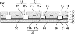
- the sound absorbing member of the present invention may be configured as shown in FIG. That is, in the sound absorbing member 600 which is an example of the sound absorbing member of the present invention, the first layer 10, the second layer 20, and the third layer 60 are sequentially laminated.
- the first layer 10 has a first major surface 11 and a second major surface 12 opposite to the first major surface 11.
- the first layer 10 has a first through hole 15 which penetrates the second major surface 12 from the first major surface 11 to form an introduction passage.
- the second major surface 12 is composed of a second major surface opening 12 a which is an end portion of the first through hole 15, and the other second major surface flat portion 12 b.
- the second layer 20 has a third major surface 21 facing the second major surface 12 and a fourth major surface 22 opposite to the third major surface 21.
- the second layer 20 has a second through hole 25 that penetrates the third major surface 21 to the fourth major surface 22.
- the third major surface 21 is composed of a third major surface opening 21 a which is an end of the second through hole 25 and the other third major surface flat portion 21 b.
- the fourth major surface 22 is composed of a fourth major surface opening 22a which is the other end of the second through hole 25 and the other fourth major surface flat 22b.
- the third layer 60 has a fifth major surface 61 facing the fourth major surface 22 and a sixth major surface 62 opposite to the fifth major surface 61.
- the opening area of the second main surface opening 12a is smaller than the opening area of the third main surface opening 21a.
- a part of the first layer 10 and the second layer 20 are adhered by the adhesive layer 40.
- the second through hole 25 forms the side surface of the hollow portion 30, and the fifth main surface 61 is the bottom surface 31 of the hollow portion 30.
- the second layer 20 and the third layer 60 are stacked by adhering the entire fourth major surface flat portion 22 and the fifth major surface 61 with the adhesive layer 40.
- a first air layer 50 is formed between the second major surface flat portion 12 b and the third major surface flat portion 21 b.
- the first air layer 50 is connected to the hollow portion 30.
- the sound absorbing member of the present invention may be configured as shown in FIG. That is, the sound absorbing member 700 which is an example of the sound absorbing member of the present invention is formed by sequentially laminating the first layer 10, the second layer 20, and the third layer 60.
- the first layer 10 has a first major surface 11 and a second major surface 12 opposite to the first major surface 11.
- the first layer 10 has a first through hole 15 which penetrates the second major surface 12 from the first major surface 11 to form an introduction passage.
- the second major surface 12 is composed of a second major surface opening 12 a which is an end portion of the first through hole 15, and the other second major surface flat portion 12 b.
- the second layer 20 has a third major surface 21 facing the second major surface 12 and a fourth major surface 22 opposite to the third major surface 21.
- the second layer 20 has a second through hole 25 that penetrates the third major surface 21 to the fourth major surface 22.
- the third major surface 21 is composed of a third major surface opening 21 a which is an end of the second through hole 25 and the other third major surface flat portion 21 b.
- the fourth major surface 22 is composed of a fourth major surface opening 22a which is the other end of the second through hole 25 and the other fourth major surface flat 22b.
- the third layer 60 has a fifth major surface 61 facing the fourth major surface 22 and a sixth major surface 62 opposite to the fifth major surface 61.
- the opening area of the second main surface opening 12a is smaller than the opening area of the third main surface opening 21a.
- a part of the first layer 10 and the second layer 20 are bonded by the adhesive layer 40.
- the second through hole 25 forms the side surface of the hollow portion 30, and the fifth main surface 61 is the bottom surface 31 of the hollow portion 30.
- the second layer 20 and the third layer 60 are laminated by bonding a part of the fourth major surface flat portion 22 and the fifth major surface by the adhesive layer 40.
- a first air layer 50 is formed between the second major surface flat portion 12 b and the third major surface flat portion 21 b.
- the first air layer 50 is connected to the hollow portion 30.
- a second air layer 70 is formed between the fourth major surface flat portion 22 and the fifth major surface 61.
- the second air layer 70 is connected to the hollow portion 30.
- the sound absorbing member of the present invention may be configured as shown in FIG. That is, the sound absorbing member 800, which is an example of the sound absorbing member of the present invention, is formed by sequentially laminating the first layer 10, the second layer 20, and the third layer 60.
- the first layer 10 has a first major surface 11 and a second major surface 12 opposite to the first major surface 11.
- the first layer 10 has a first through hole 15 which penetrates the second major surface 12 from the first major surface 11 to form an introduction passage.
- the second major surface 12 is composed of a second major surface opening 12 a which is an end portion of the first through hole 15, and the other second major surface flat portion 12 b.
- the second layer 20 has a third major surface 21 facing the second major surface 12 and a fourth major surface 22 opposite to the third major surface 21.
- the second layer 20 has a second through hole 25 that penetrates the third major surface 21 to the fourth major surface 22.
- the third major surface 21 is composed of a third major surface opening 21 a which is an end of the second through hole 25 and the other third major surface flat portion 21 b.
- the fourth major surface 22 is composed of a fourth major surface opening 22a which is the other end of the second through hole 25 and the other fourth major surface flat 22b.
- the third layer 60 has a fifth major surface 61 facing the fourth major surface 22 and a sixth major surface 62 opposite to the fifth major surface 61.
- the opening area of the second main surface opening 12a is smaller than the opening area of the third main surface opening 21a.
- the second through hole 25 forms the side surface of the hollow portion 30, and the fifth main surface 61 is the bottom surface 31 of the hollow portion 30.
- the male portion 12 ⁇ is formed in the second main surface flat portion 12b
- the female portion 21 ⁇ is formed in the third main surface flat portion 21b.
- the layer 10 and the second layer 20 are connected. Further, the second major surface flat portion 12b and the third major surface flat portion 21b are not in contact with each other except the male portion 12 ⁇ and the female portion 21 ⁇ , and the second major surface flat portion 12b and the third major surface flat
- the first air layer 50 is formed between the portion 21b.
- a female portion 22 ⁇ is formed in the fourth main surface flat portion 22b, and a male portion 61 ⁇ is formed in the fifth main surface, and these are fitted together to form the second layer 20 , And the third layer 60 are connected. Further, the fourth major surface flat portion 22 b and the fifth major surface 61 are not in contact with each other except for the female portion 22 ⁇ and the male portion 61 ⁇ , and the fourth major surface flat portion 22 b and the fifth major surface 61 A second air layer 70 is formed between them. The second air layer 70 is connected to the hollow portion 30. By forming the second air layer 70, the sound absorption coefficient is improved by the spring mass effect.
- the sound absorbing member of the present invention may be configured as shown in FIG. That is, the sound absorbing member 900, which is an example of the sound absorbing member of the present invention, is formed by sequentially laminating the first layer 10, the second layer 20, and the third layer 60.
- the first layer 10 has a first major surface 11 and a second major surface 12 opposite to the first major surface 11.
- the first layer 10 has a first through hole 15 which penetrates the second major surface 12 from the first major surface 11 to form an introduction passage.
- the second major surface 12 is composed of a second major surface opening 12 a which is an end portion of the first through hole 15, and the other second major surface flat portion 12 b.
- the second layer 20 has a third major surface 21 facing the second major surface 12 and a fourth major surface 22 opposite to the third major surface 21.
- the second layer 20 has a second through hole 25 that penetrates the third major surface 21 to the fourth major surface 22.
- the third major surface 21 is composed of a third major surface opening 21 a which is an end of the second through hole 25 and the other third major surface flat portion 21 b.
- the fourth major surface 22 is composed of a fourth major surface opening 22a which is the other end of the second through hole 25 and the other fourth major surface flat 22b.
- the third layer 60 has a fifth major surface 61 facing the fourth major surface 22 and a sixth major surface 62 opposite to the fifth major surface 61.
- the opening area of the second main surface opening 12a is smaller than the opening area of the third main surface opening 21a.
- the second through hole 25 forms the side surface of the hollow portion 30, and the fifth main surface 61 is the bottom surface 31 of the hollow portion 30.
- the second main surface flat portion 12b and the third main surface flat portion 21b are bonded by an adhesive at the end. Further, the first layer 10 is curved to be convex upward, and the first air layer 50 is formed between the second major surface flat portion 12 b and the third major surface flat portion 21 b. . That is, the second major surface flat portion 12b is curved so as to be convex upward.
- the first air layer 50 is connected to the hollow portion 30.
- the fourth major surface flat portion 22b and the fifth major surface 61 are bonded by an adhesive at the end. Further, the third layer 60 is curved to be convex downward, and a second air layer 70 is formed between the fourth major surface flat portion 22 b and the fifth major surface 61. That is, the fifth major surface 61 is curved to be convex downward.
- the second air layer 70 is connected to the hollow portion 30. By forming the second air layer 70, the sound absorption coefficient is improved by the spring mass effect.
- the method for producing the sound absorbing member of the present invention is Producing an upper layer which is a plate material having a columnar first through hole serving as an introduction passage; Producing a second layer which is a plate material having a second through hole; Preparing a plate material to be the third layer; Laminating the first layer and the second layer such that a first air layer is formed between the second main surface flat portion of the first layer and the third main surface flat portion of the second layer; And laminating the second layer and the third layer such that the hollow portion is formed.
- a plate material of a predetermined thickness made of a material such as a resin that can be used as a plate material is prepared.
- the first layer can be produced by forming the first through hole with a means such as punching, drill or laser for a plate material having no through hole.
- a foamed resin comprising expandable resin particles (beads) as a plate material
- the plate is also provided with a protrusion for forming the first through hole in the mold to foam the expandable resin particles.
- a first layer provided with a first through hole can be manufactured.
- a plate material of a predetermined thickness made of a material such as a resin that can be used as a plate material is prepared.
- the second layer can be produced by forming the second through hole by means of punching, drilling, laser or the like for the plate material having no through hole.
- the diameter of the second through hole is made larger than that of the first through hole.
- the plate is also provided with a projection for forming the second through hole in the mold to foam the expandable resin particles.
- a second layer provided with a second through hole can be manufactured.
- the fitting portion (male portion or female portion) is formed on the third major surface flat portion of the second layer. May be Moreover, you may form a fitting part (male part or female part) in the 4th main surface flat part of a 2nd layer in the process of laminating
- Step of preparing plate material to be the third layer A plate made of a material such as resin that can be used as a plate and having a predetermined thickness without a through hole is prepared.
- a fitting part male part or female part
- Step of laminating the first layer and the second layer Next, in the case of bonding the first layer and the second layer with an adhesive, a sheet-like adhesive is prepared in accordance with the shape and position of the second through hole of the second layer. At this time, the sheet-like adhesive layer is processed so that the first air layer is formed between the second main surface flat portion of the first layer and the third main surface flat portion of the second layer. .
- the first layer and the second layer can be bonded by the adhesive layer by exerting the adhesive force of the adhesive by sandwiching the first layer and the second layer.
- the adhesive is applied according to the shape and position of the second through hole of the second layer, the first layer and the second layer are laminated, and the adhesive force of the adhesive is exhibited, thereby the first layer and the second layer Can be adhered by an adhesive layer.
- the conditions for exerting the adhesive strength of the adhesive conditions in accordance with the adhesive characteristics of the adhesive may be used.
- Step of laminating the second layer and the third layer a sheet-like adhesive is prepared in accordance with the shape and position of the second through hole of the second layer.
- a sheet-like adhesive is prepared in accordance with the shape and position of the second through hole of the second layer.
- the second layer and the third layer can be bonded by the adhesive layer by exerting the adhesive force of the adhesive by sandwiching the second layer and the third layer. Thereby, a hollow part can be formed.
- the parts for vehicles of the present invention are characterized by including the sound absorbing member of the present invention. Since the sound absorbing member of the present invention is excellent in sound absorbing performance, it is excellent as a component for a vehicle. As parts for vehicles provided with the sound absorption member of the present invention, a raising member, a partition member, a luggage box, etc. are mentioned.
- An automobile according to the present invention is characterized in that the introduction passage of the sound absorbing member according to the present invention is disposed in the direction of the road surface.
- the sound absorbing member of the present invention is used as a vehicle component.
- An example in which the sound absorbing member of the present invention is used as a component for a vehicle and an example of an automobile in which the sound absorbing member of the present invention is disposed will be described with reference to FIGS. 10 (a) and 10 (b).
- Fig.10 (a) is explanatory drawing which shows typically an example of the site
- FIG.10 (b) is partial expansion of the area
- the automobile 1 includes a luggage room 3 at the rear of the rear seat 2.
- a plate-like floor member 4 is laid, and under the floor member 4, an underfloor space 5 is present.
- the sound absorbing member 100 is disposed under the underfloor space 5 of the automobile 1 such that the introduction passage 15 faces the road surface.
- Example 1 Preparation of Plate Material (1-1) Preparation of Plate Material to be First Layer Primary foamed particles (made of polypropylene, average particle diameter 3.5 mm, foaming agent: carbon dioxide) prepared by prefoaming expandable resin particles are made of gold. It is made of foamed resin by filling it in a mold, foaming it with heating steam (143 ° C, 10 seconds), removing it from the mold, and drying it at 80 ° C for 12 hours. A plate material having a size of 10 mm and serving as a first layer in which a fitting portion which is a male portion was formed at an edge portion of one main surface was produced. At this time, the expansion ratio of the foamed resin was 30 times.
- Primary foamed particles made of polypropylene, average particle diameter 3.5 mm, foaming agent: carbon dioxide
- prefoaming expandable resin particles are made of gold. It is made of foamed resin by filling it in a mold, foaming it with heating steam (143 ° C, 10 seconds), removing
- first through holes having a diameter of 3 mm are formed in the plate material to be the first layer manufactured in the above (1-1) so as to form a staggered arrangement of the hole pitch 10 mm.
- the first layer was prepared.
- a through hole (second through hole) is formed in a circular shape with a diameter of 10 mm in the plate material to be the second layer produced in the above (1-2) so as to form a staggered arrangement of hole pitch 10 mm, and a second layer is produced did.
- Example 2 (1) Preparation of Plate Material Primary foam particles (made of polypropylene, average particle diameter: 3.5 mm, foaming agent: carbon dioxide) prepared by prefoaming foamable resin particles are filled in a mold and foam molding is performed by heating steam (143) C. for 10 seconds, removed from the mold, and dried at 80.degree. C. for 12 hours to produce three plate members of 800 mm long x 800 mm wide x 10 mm thick made of a foamed resin. At this time, the expansion ratio of the foamed resin was 30 times.
- foaming agent carbon dioxide
- first through holes having a diameter of 3 mm are formed in one of the plate materials manufactured in the above (1) so as to form a staggered arrangement of the hole pitch 10 mm.
- the first layer was made.
- a through hole (second through hole) having a diameter of 10 mm is formed in another one of the plate materials manufactured in the above (1) so as to form a staggered arrangement of the hole pitch 10 mm, and the second layer is formed.
- the remaining one plate material produced in the above (1) was not processed but was used as the third layer.
- the first air layer was formed between the second main surface flat portion of the first layer and the third main surface flat portion of the second layer to which the adhesive is not applied.
- an adhesive Konishi HONDA G CO., LTD.
- an adhesive Konishi HONDA G CO., LTD.
- a second air layer was formed between the flat surface of the fourth main surface of the second layer to which the adhesive was not applied and the fifth main surface of the third layer.
- a sound absorbing member according to Example 2 having the structure shown in FIG. 7 was manufactured.
- the distance between the second main surface flat portion and the third main surface flat portion is 100 ⁇ m
- the distance between the fourth main surface flat portion and the fifth main surface is 100 ⁇ m. Met.
- FIG. 11 is an explanatory view schematically showing a reverberation chamber method sound absorption coefficient with respect to the sound absorption member.
- the sound absorbing member 100 according to each example and each comparative example is placed on the floor surface 81 of the reverberation chamber 80 with the opening of the introduction passage as the upper surface, In the reverberation chamber 80, the noise signal generator 82 radiates electrical noise through the speaker 83.
- the sound emission is then stopped, the sound is measured by the microphone 84 and the attenuation process is analyzed by the signal analyzer 85.
- the reverberation time which is the time for the sound to attenuate 60 dB from the analyzed attenuation curve before the test body is placed, T1 [sec. After the test body is placed on the floor surface, a reverberation time, which is a time when the sound attenuates by 60 dB from the measured attenuation curve, is T2 [sec. Ask for The measurement is performed at 300-5000 Hz.
- FIG. 12 is a graph showing the results of a reverberation chamber method sound absorption coefficient test of the sound absorbing member according to the first embodiment of the present invention.
- FIG. 13 is a graph showing the results of a reverberation chamber method sound absorption coefficient test of a sound absorbing member according to a second embodiment of the present invention.
- FIG. 14 is a graph showing the results of a reverberation chamber method sound absorption coefficient test of a sound absorbing member according to Comparative Example 1 of the present invention.
- the sound absorbing performance was high, and particularly, the peak of the sound absorption coefficient was high.
Abstract
導入通路と上記導入通路を介して外部と接続される中空部からなるヘルムホルツ共鳴構造を有する吸音部材であって、上記吸音部材は、第1層と、上記第1層に積層された第2層を含み、上記第1層は、第1主面及び上記第1主面と反対側の第2主面とを有し、上記第2層は、上記第2主面と対面する第3主面及び上記第3主面と反対側の第4主面を有し、上記第1層は、上記第1主面から上記第2主面を貫通し、上記導入通路を形成する第1貫通孔を有し、上記第2主面は、上記第1貫通孔の端部である第2主面開口部と、それ以外の第2主面平坦部とからなり、上記第3主面は、上記中空部の端部である第3主面開口部と、それ以外の第3主面平坦部とからなり、上記第2主面開口部の開口面積は、上記第3主面開口部の開口面積よりも小さく、上記第2主面平坦部と、上記第3主面平坦部との間の少なくとも一部には、第1空気層が形成されていることを特徴とする吸音部材。
Description
本発明は、吸音部材、車両用部品及び自動車に関する。
自動車等の車両は、エンジンなどの動力源を有し、人の操作によって移動できる機械であり、様々な振動や騒音を発生させる。車両内に伝達される音としては、動力源が発する音だけではなく、車両が走行する際に発生するロードノイズ、タイヤパターンノイズ、風切音等の、車両の外で発生する音も含まれる。これらの音が車両内に伝達されてしまうと、人に対して不快感を与えてしまうため、エンジン、エンジンルーム内、内装、ボディ、排気管周辺等において、遮音材・吸音部材を用いて防音対策が行われている。
また、自動車の技術改良に伴い、自動車に対する新たな防音対策の必要が生じている。例えば、自動車の燃費向上の方策の一つとして、自動車の重心及び最低地上高を下げることが検討されている。自動車の重心を下げることで車両の安定感及び操作性が向上し、最低地上高を下げることで空気抵抗を低減することができる。しかしながら、自動車の最低地上高が低くなることで、走行時に車両と路面との間を流れる空気の粘性が高まる。そうすると、タイヤパターンノイズ(500~3000Hzの周波数領域であり、単にパターンノイズともいう)等の走行時に路面から発生する騒音が車体下の周囲に反射・拡散しにくく、車両内に侵入する音の度合いが高くなると推定される。同様の問題は電気自動車でも起こりうる。
従って、自動車の燃費向上のために自動車の重心及び最低地上高を下げた場合、従来は自動車外に拡散していた騒音が、自動車に乗車している人に伝達されてしまうことが想定される。特に、車両後部、かつ、収容スペースが配置されているラゲッジルーム下部(床下空間)の底部からこれらの騒音が侵入しやすいと考えられる。これらの騒音には人が不快に感じる500~2000Hzの周波数領域の騒音も含まれるため、その対策が求められている。
特許文献1には、発泡成形により成形された柔軟な多孔質発泡体に、一方の面に開口する導入通路と、該導入通路の奥に形成され該導入通路よりも大きな断面積を持つ中空部とからなる多数の共鳴室を有する吸音部材が開示されている。
特許文献2には、表面又は裏面に開口部を有する複数個の独立した盲空洞を有する樹脂成形体と吸音部材を備え、特定の100Hz~10kHz共鳴吸音ピーク周波数を有する吸・遮音構造体が開示されている。
ここで、特許文献1に記載された吸音部材や特許文献2に記載された樹脂成形体には、ヘルムホルツ共鳴構造と呼ばれる孔が形成されている。
ヘルムホルツ共鳴構造は、表面に開口する導入通路と、導入通路を介して外部と接続される中空部からなる。
ヘルムホルツ共鳴構造は、表面に開口する導入通路と、導入通路を介して外部と接続される中空部からなる。
ヘルムホルツ共鳴構造の導入通路に音が到達すると、導入通路の空気は、音に押され中空部に入ろうとする。
この際、空気は弾性体なので中空部の空気は、導入通路の空気を外に押し出そうとする。すなわち、中空部の空気はバネとして機能することになる。
この場合、導入通路の空気の動きは、単振動の動きとして表すことができ、この周波数において、導入通路に到達した音は共鳴し打ち消されることになる。すなわち、吸音されることになる。
この際、空気は弾性体なので中空部の空気は、導入通路の空気を外に押し出そうとする。すなわち、中空部の空気はバネとして機能することになる。
この場合、導入通路の空気の動きは、単振動の動きとして表すことができ、この周波数において、導入通路に到達した音は共鳴し打ち消されることになる。すなわち、吸音されることになる。
このように、ヘルムホルツ共鳴構造は、所定の周波数の音を吸収することができるが、その吸音周波数は、中空部の体積、並びに、導入通路の長さ及び開口面積に依存する。
そのため、中空部の体積、並びに、導入通路の長さ及び開口面積を調節することにより吸音周波数を調節することができる。
そのため、中空部の体積、並びに、導入通路の長さ及び開口面積を調節することにより吸音周波数を調節することができる。
その一方で、吸音部材の吸音率の向上も望まれていた。
特に、吸音部材を車両に用いる場合には、収容スペースが限られているので、従来の大きさと同等又はそれ以下の大きさであり、かつ、吸音率が高い吸音部材の開発が求められていた。
特に、吸音部材を車両に用いる場合には、収容スペースが限られているので、従来の大きさと同等又はそれ以下の大きさであり、かつ、吸音率が高い吸音部材の開発が求められていた。
本発明は、上記問題点を解決するためになされた発明であり、本発明は、吸音率が充分に高い吸音部材を提供することを目的とする。
本発明の吸音部材は、導入通路と上記導入通路を介して外部と接続される中空部からなるヘルムホルツ共鳴構造を有する吸音部材であって、
上記吸音部材は、第1層と、上記第1層に積層された第2層を含み、
上記第1層は、第1主面及び上記第1主面と反対側の第2主面とを有し、
上記第2層は、上記第2主面と対面する第3主面及び上記第3主面と反対側の第4主面を有し、
上記第1層は、上記第1主面から上記第2主面を貫通し、上記導入通路を形成する第1貫通孔を有し、
上記第2主面は、上記第1貫通孔の端部である第2主面開口部と、それ以外の第2主面平坦部とからなり、
上記第3主面は、上記中空部の端部である第3主面開口部と、それ以外の第3主面平坦部とからなり、
上記第2主面開口部の開口面積は、上記第3主面開口部の開口面積よりも小さく、
上記第2主面平坦部と、上記第3主面平坦部との間の少なくとも一部には、第1空気層が形成されていることを特徴とする。
本発明の吸音部材は、導入通路を形成する第1層と、中空部を形成する第2層とが積層された吸音部材でありヘルムホルツ共鳴構造を有する。そのため、所定の周波数の音を効率よく吸収することができる。
さらに、本発明の吸音部材では、第1層の第2主面平坦部と、第2層の第3主面平坦部との間の少なくとも一部には、第1空気層が形成されている。吸音部材がこのような構造であると、吸音率が向上する。
さらに、本発明の吸音部材では、第1層の第2主面平坦部と、第2層の第3主面平坦部との間の少なくとも一部には、第1空気層が形成されている。吸音部材がこのような構造であると、吸音率が向上する。
本発明の吸音部材では、上記第2主面平坦部と上記第3主面平坦部とは、一部が接触していてもよい。
第2主面平坦部と第3主面平坦部との一部が接触していたとしても、第2主面平坦部と第3主面平坦部との間の一部に、第1空気層が形成されていれば吸音率が向上する。
第2主面平坦部と第3主面平坦部との一部が接触していたとしても、第2主面平坦部と第3主面平坦部との間の一部に、第1空気層が形成されていれば吸音率が向上する。
また、上記第2主面平坦部と上記第3主面平坦部は、その少なくとも一方に湾曲又はうねりがあり、上記第2主面平坦部と上記第3主面平坦部とは、一部が接触していてもよい。
第2主面平坦部と第3主面平坦部の少なくとも一方に湾曲又はうねりがあることにより、第1空気層を形成させることができ、吸音率を向上させることができる。
第2主面平坦部と第3主面平坦部の少なくとも一方に湾曲又はうねりがあることにより、第1空気層を形成させることができ、吸音率を向上させることができる。
本発明の吸音部材では、上記中空部の底面は、上記第2層にあってもよい。
このような構造の吸音部材では、第2層が、中空部を形成する非貫通孔を有することになる。
このような構造の吸音部材は、第1層及び第2層を積層することにより製造することができる。
このような構造の吸音部材では、第2層が、中空部を形成する非貫通孔を有することになる。
このような構造の吸音部材は、第1層及び第2層を積層することにより製造することができる。
本発明の吸音部材では、上記第2層の下層には、上記第4主面と対面する第5主面と、上記第5主面と反対側の第6主面を有する第3層が積層されており、上記第2層には、上記第3主面から上記第4主面を貫通し、上記中空部の側面を形成する第2貫通孔を有し、上記第5主面は、上記中空部の底面を形成していてもよい。
一つの層に非貫通孔を形成し中空部とするよりも、一つの層に中空部の側面となる貫通孔を形成し、その下に中空部の底面となる層を積層して中空部を形成した方が、効率的に吸音部材を製造することができる。
すなわち、このような構造の吸音部材は、製造効率が高い。
一つの層に非貫通孔を形成し中空部とするよりも、一つの層に中空部の側面となる貫通孔を形成し、その下に中空部の底面となる層を積層して中空部を形成した方が、効率的に吸音部材を製造することができる。
すなわち、このような構造の吸音部材は、製造効率が高い。
本発明の吸音部材では、上記第4主面は、上記第2貫通孔の端部である第4主面開口部と、それ以外の第4主面平坦部とからなり、上記第4主面平坦部と上記第5主面との間の少なくとも一部には、第2空気層が形成されていることが望ましい。
第1空気層に加え、第2層の第4主面平坦部と第3層の第5主面との間の少なくとも一部には、第2空気層があると、吸音効率がさらに向上する。
第1空気層に加え、第2層の第4主面平坦部と第3層の第5主面との間の少なくとも一部には、第2空気層があると、吸音効率がさらに向上する。
本発明の吸音部材では、上記第4主面平坦部と上記第5主面とは、一部が接触していてもよい。
第4主面平坦部と第5主面との一部が接触していたとしても、第4主面平坦部と第5主面との間の一部に、第2空気層が形成されていれば吸音率が向上する。
第4主面平坦部と第5主面との一部が接触していたとしても、第4主面平坦部と第5主面との間の一部に、第2空気層が形成されていれば吸音率が向上する。
また、上記第4主面平坦部と上記第5主面は、その少なくとも一方に湾曲又はうねりがあり、上記第4主面平坦部と上記第5主面とは、一部が接触していてもよい。
第4主面平坦部と第5主面の少なくとも一方に湾曲又はうねりがあることにより、第2空気層を形成させることができ、吸音率を向上させることができる。
第4主面平坦部と第5主面の少なくとも一方に湾曲又はうねりがあることにより、第2空気層を形成させることができ、吸音率を向上させることができる。
本発明の吸音部材では、上記第1主面は、上記第1貫通孔の端部である第1主面開口部と、それ以外の第1主面平坦部とからなり、上記第1主面平坦部には、さらに繊維層が形成されてなることが望ましい。
吸音部材がヘルムホルツ共鳴構造を有すると、所定の周波数領域の音を吸音することができるが、吸音できる周波数領域の幅は広くなく、特に、2000Hz以上の高周波数領域の音を充分に吸収しにくい。
しかし、繊維層が形成されていると、2000Hz以上の高周波数領域の音を吸音することができる。
吸音部材がヘルムホルツ共鳴構造を有すると、所定の周波数領域の音を吸音することができるが、吸音できる周波数領域の幅は広くなく、特に、2000Hz以上の高周波数領域の音を充分に吸収しにくい。
しかし、繊維層が形成されていると、2000Hz以上の高周波数領域の音を吸音することができる。
本発明の吸音部材は、樹脂及び/又は繊維質材料からなることが望ましい。上記樹脂は、発泡樹脂、ゴムなどのエラストマーであることが望ましい。
吸音部材が樹脂製であると、軽量化が図りやすいため車両用部品として特に望ましい。
また、樹脂が発泡樹脂であると、その重量をより軽くすることができ、車両用部品とした場合に燃費の向上に寄与することができる。
本発明においては、樹脂及び繊維の複合材であってもよい。複合化の方法としては、樹脂と繊維を混合してもよく、樹脂と繊維をブロック状に組み合わせてもよく、樹脂と繊維の板状体を積層してもよい。
吸音部材が樹脂製であると、軽量化が図りやすいため車両用部品として特に望ましい。
また、樹脂が発泡樹脂であると、その重量をより軽くすることができ、車両用部品とした場合に燃費の向上に寄与することができる。
本発明においては、樹脂及び繊維の複合材であってもよい。複合化の方法としては、樹脂と繊維を混合してもよく、樹脂と繊維をブロック状に組み合わせてもよく、樹脂と繊維の板状体を積層してもよい。
本発明の車両用部品は、本発明の吸音部材を備えることを特徴とする。
本発明の吸音部材は吸音性能に優れるため、車両用部品として優れる。
本発明の吸音部材を備える車両用部品としては、嵩上げ材、仕切り部材、ラゲッジボックス等が挙げられる。
本発明の吸音部材は吸音性能に優れるため、車両用部品として優れる。
本発明の吸音部材を備える車両用部品としては、嵩上げ材、仕切り部材、ラゲッジボックス等が挙げられる。
本発明の自動車は、本発明の吸音部材の導入通路を路面方向に向けて配置してなることを特徴とする。
このような向きに本発明の吸音部材を配置することで、路面から伝わるタイヤパターンノイズの騒音を吸収することができ、騒音が車内に伝わることを防止することができる。
このような向きに本発明の吸音部材を配置することで、路面から伝わるタイヤパターンノイズの騒音を吸収することができ、騒音が車内に伝わることを防止することができる。
(発明の詳細な説明)
以下、本発明について具体的に説明する。本発明は、以下の記載に限定されるものではなく、本発明の要旨を変更しない範囲において適宜変更して適用することができる。
以下、本発明について具体的に説明する。本発明は、以下の記載に限定されるものではなく、本発明の要旨を変更しない範囲において適宜変更して適用することができる。
本発明の吸音部材は、導入通路と上記導入通路を介して外部と接続される中空部からなるヘルムホルツ共鳴構造を有する吸音部材であって、
上記吸音部材は、第1層と、上記第1層に積層された第2層を含み、
上記第1層は、第1主面及び上記第1主面と反対側の第2主面とを有し、
上記第2層は、上記第2主面と対面する第3主面及び上記第3主面と反対側の第4主面を有し、
上記第1層は、上記第1主面から上記第2主面を貫通し、上記導入通路を形成する第1貫通孔を有し、
上記第2主面は、上記第1貫通孔の端部である第2主面開口部と、それ以外の第2主面平坦部とからなり、
上記第3主面は、上記中空部の端部である第3主面開口部と、それ以外の第3主面平坦部とからなり、
上記第2主面開口部の開口面積は、上記第3主面開口部の開口面積よりも小さく、
上記第2主面平坦部と、上記第3主面平坦部との間の少なくとも一部には、第1空気層が形成されていることを特徴とする。
上記吸音部材は、第1層と、上記第1層に積層された第2層を含み、
上記第1層は、第1主面及び上記第1主面と反対側の第2主面とを有し、
上記第2層は、上記第2主面と対面する第3主面及び上記第3主面と反対側の第4主面を有し、
上記第1層は、上記第1主面から上記第2主面を貫通し、上記導入通路を形成する第1貫通孔を有し、
上記第2主面は、上記第1貫通孔の端部である第2主面開口部と、それ以外の第2主面平坦部とからなり、
上記第3主面は、上記中空部の端部である第3主面開口部と、それ以外の第3主面平坦部とからなり、
上記第2主面開口部の開口面積は、上記第3主面開口部の開口面積よりも小さく、
上記第2主面平坦部と、上記第3主面平坦部との間の少なくとも一部には、第1空気層が形成されていることを特徴とする。
本発明の吸音部材は、導入通路を形成する第1層と、中空部を形成する第2層とが積層された吸音部材でありヘルムホルツ共鳴構造を有する。そのため、所定の周波数の音を効率よく吸収することができる。
さらに、本発明の吸音部材では、第1層の第2主面平坦部と、第2層の第3主面平坦部との間の少なくとも一部には、第1空気層が形成されている。吸音部材がこのような構造であると、吸音率が向上する。
さらに、本発明の吸音部材では、第1層の第2主面平坦部と、第2層の第3主面平坦部との間の少なくとも一部には、第1空気層が形成されている。吸音部材がこのような構造であると、吸音率が向上する。
本発明の吸音部材では、第1空気層が、中空部と繋がっていてもよく、中空部と繋がっていなくてもよいが、中空部と繋がっている方がより望ましい。
第1空気層が中空部と繋がっていると吸音率が向上する。
第1空気層が中空部と繋がっていると吸音率が向上する。
本発明の吸音部材では、第2主面平坦部と第3主面平坦部とは、一部が接触していてもよい。
第2主面平坦部と第3主面平坦部との一部が接触していたとしても、第2主面平坦部と第3主面平坦部との間の一部に、第1空気層が形成されていれば吸音率が向上する。
第2主面平坦部と第3主面平坦部との一部が接触していたとしても、第2主面平坦部と第3主面平坦部との間の一部に、第1空気層が形成されていれば吸音率が向上する。
また、本発明の吸音部材では、第1空気層を形成するために第2主面平坦部と第3主面平坦部との間にスペーサーを設けてもよく、設けなくてもよい。
スペーサーを設けることにより、本発明の吸音部材に確実に第1空気層を形成することができる。
スペーサーを設けない場合には、バネマス効果がスペーサーにより減殺されないため有利である。
スペーサーを設けることにより、本発明の吸音部材に確実に第1空気層を形成することができる。
スペーサーを設けない場合には、バネマス効果がスペーサーにより減殺されないため有利である。
本発明の吸音部材は、その全体の厚さが10~120mmであることが望ましい。吸音部材の厚さは、20~100mmであることがさらに望ましい。
吸音部材の厚さが、10mm未満である場合、ヘルムホルツ共鳴構造を形成しにくくなる。
吸音部材の厚さが、120mmを超える場合、吸音部材が大きくなりすぎ、所望のスペースに配置しにくくなる。
吸音部材の厚さが、10mm未満である場合、ヘルムホルツ共鳴構造を形成しにくくなる。
吸音部材の厚さが、120mmを超える場合、吸音部材が大きくなりすぎ、所望のスペースに配置しにくくなる。
上記の通り、本発明の吸音部材では、導入通路(第1貫通孔)の開口部の円相当径は、1~30mmであることが望ましく、3~25mmであることがより望ましい。
また、導入通路(第1貫通孔)の長さは、1~20mmであることが望ましく、3~15mmであることがより望ましい。
また、中空部の体積は、24~329,860mm3であることが望ましく、257~246,766mm3であることがより望ましい。
また、導入通路(第1貫通孔)の長さは、1~20mmであることが望ましく、3~15mmであることがより望ましい。
また、中空部の体積は、24~329,860mm3であることが望ましく、257~246,766mm3であることがより望ましい。
本発明の吸音部材では、吸音部材が第1層及び第2層の2つの層からなっていてもよく、第1層、第2層及び第3層の3つの層からなっていてもよい。
以下に、吸音部材が2つの層からなる場合と、吸音部材が3つの場合からなる場合に分けて説明する。
以下に、吸音部材が2つの層からなる場合と、吸音部材が3つの場合からなる場合に分けて説明する。
まず、吸音部材が2つの層からなる場合について説明する。
この場合、本発明の吸音部材では、中空部の底面が第2層にあることになる。
すなわち、本発明の吸音部材では、第2層が、中空部を形成する非貫通孔を有することになる。
このような構造であると、第1層及び第2層を積層することによりヘルムホルツ共鳴構造を有する本発明の吸音部材を製造することができる。
この場合、本発明の吸音部材では、中空部の底面が第2層にあることになる。
すなわち、本発明の吸音部材では、第2層が、中空部を形成する非貫通孔を有することになる。
このような構造であると、第1層及び第2層を積層することによりヘルムホルツ共鳴構造を有する本発明の吸音部材を製造することができる。
また、第1層と第2層とは、第1層の第2主面平坦部と、第2層の第3主面平坦部との間に第1空気層が形成されてさえいれば、どのように積層されていても構わない。
例えば、第2主面平坦部及び第3主面平坦部との間の一部に接着剤層を形成し第1層及び第2層を積層してもよい。この際、第1層と第2層の端部のみで第1層と第2層とを接着してもよい。
また、第2主面平坦部及び第3主面平坦部に嵌合部(雄部及び雌部)を形成し、これらを嵌合させて第1層及び第2層を積層してもよい。
例えば、第2主面平坦部及び第3主面平坦部との間の一部に接着剤層を形成し第1層及び第2層を積層してもよい。この際、第1層と第2層の端部のみで第1層と第2層とを接着してもよい。
また、第2主面平坦部及び第3主面平坦部に嵌合部(雄部及び雌部)を形成し、これらを嵌合させて第1層及び第2層を積層してもよい。
本発明の吸音部材では、第1貫通孔は、円柱状であることが望ましく、長さ方向に垂直な方向の断面形状が真円であることが望ましい。第1貫通孔が円柱状であると導入通路は円柱状となる。導入通路が円柱状であると、吸音特性に異方性がないため有利である。
本発明の吸音部材では、第1貫通孔が円柱状である場合の底面の直径は、1~30mmであることが好ましい。
すなわち、本発明の吸音部材では、導入通路の内径は1~30mmであることが好ましい。
また、第1貫通孔の形状が円柱状でない場合、第1貫通孔の径は円相当径として定める。円相当径とは、第1貫通孔を長さ方向に対して垂直な方向に切断した際の第1貫通孔の断面積を、同面積の真円に置き換えた場合の直径である。第1貫通孔の断面形状が真円の場合にはその直径をそのまま円相当径とすればよい。
本発明の吸音部材では、第1貫通孔が円柱状である場合の底面の直径は、1~30mmであることが好ましい。
すなわち、本発明の吸音部材では、導入通路の内径は1~30mmであることが好ましい。
また、第1貫通孔の形状が円柱状でない場合、第1貫通孔の径は円相当径として定める。円相当径とは、第1貫通孔を長さ方向に対して垂直な方向に切断した際の第1貫通孔の断面積を、同面積の真円に置き換えた場合の直径である。第1貫通孔の断面形状が真円の場合にはその直径をそのまま円相当径とすればよい。
本発明の吸音部材において、第1層に設けられる第1貫通孔の配列パターンは、正方形を縦横に連続して配置した平面において正方形の頂点に第1貫通孔を配置する正方配列であってもよく、正三角形を縦横に連続して配置した平面において三角形の頂点に第1貫通孔を配置する千鳥配列であってもよい。
これらの中では、千鳥配列であることが望ましい。第1貫通孔の配列パターンが千鳥配列であると、隣接する第1貫通孔が全て等間隔となりやすいため、吸音効果が向上する。また、第1層の板材としての強度が得られる。
これらの中では、千鳥配列であることが望ましい。第1貫通孔の配列パターンが千鳥配列であると、隣接する第1貫通孔が全て等間隔となりやすいため、吸音効果が向上する。また、第1層の板材としての強度が得られる。
本発明の吸音部材において、第1層を構成する板材は樹脂からなることが好ましい。
上記樹脂は、発泡樹脂、ゴムなどのエラストマーであることが望ましい。
第1層を構成する板材が樹脂製であると、軽量化が図りやすいため車両用部品として特に望ましい。
また、樹脂が発泡樹脂であると、その重量をより軽くすることができ、車両用部品とした場合に燃費の向上に寄与することができる。
本発明の吸音部材において、第1層を構成する板材は、樹脂及び繊維の複合材であってもよい。複合化の方法としては、樹脂と繊維を混合してもよく、樹脂と繊維をブロック状に組み合わせてもよく、樹脂と繊維の板状体を積層してもよい。
上記樹脂は、発泡樹脂、ゴムなどのエラストマーであることが望ましい。
第1層を構成する板材が樹脂製であると、軽量化が図りやすいため車両用部品として特に望ましい。
また、樹脂が発泡樹脂であると、その重量をより軽くすることができ、車両用部品とした場合に燃費の向上に寄与することができる。
本発明の吸音部材において、第1層を構成する板材は、樹脂及び繊維の複合材であってもよい。複合化の方法としては、樹脂と繊維を混合してもよく、樹脂と繊維をブロック状に組み合わせてもよく、樹脂と繊維の板状体を積層してもよい。
樹脂としては、発泡性樹脂粒子(ビーズ)からなる発泡樹脂、気泡を有する発泡樹脂、熱可塑性樹脂、熱硬化性樹脂のいずれかであることが望ましい。
上記樹脂の密度が0.01~1g/cm3である材料であることが好ましく、さらに、樹脂の密度が0.02~0.1g/cm3であることがさらに好ましい。なお、上記樹脂が発泡樹脂である場合、樹脂の密度は、発泡成形された発泡樹脂の密度を指す。
樹脂の密度が上記範囲内であると、吸音部材として必要な強度を得やすい。
一方、樹脂の密度が0.01g/cm3未満であると、吸音部材として充分な機械的強度を得られないことがある。また樹脂の密度が1g/cm3を超える場合には、吸音部材の重量が増加してしまい、車両の軽量化の妨げとなる。
また、樹脂は、発泡性樹脂粒子(ビーズ)からなる発泡樹脂がより望ましい。樹脂が発泡性樹脂粒子(ビーズ)からなる発泡樹脂であると、強度を維持したまま吸音部材の重量を軽くすることができ、車両用部品に使用した場合に燃費の向上に寄与することができる。
なお、発泡樹脂は、発泡性樹脂粒子を発泡・成形して得られる。
本発明の吸音部材において、第1層を構成する板材として使用される発泡性樹脂粒子(ビーズ)は、樹脂粒子の内部に発泡剤を含有する粒子であり、公知のものを好適に使用することができる。
発泡性樹脂粒子を構成する樹脂成分としては、例えば、ポリエチレン、ポリプロピレン等のオレフィン系樹脂、ポリスチレン等のスチレン系樹脂が挙げられる。
スチレン系樹脂としては、スチレン単重合体、スチレン及びスチレンと共重合可能な単量体(又はその誘導体)を共重合して得られる共重合体が挙げられる。スチレン共重合体は、ブロック共重合体、ランダム共重合体、グラフト共重合体のいずれであってもよい。
発泡剤としては、例えば、プロパン、ブタン、ペンタン等の炭化水素類等が挙げられる。
発泡性樹脂粒子を構成する樹脂成分としては、例えば、ポリエチレン、ポリプロピレン等のオレフィン系樹脂、ポリスチレン等のスチレン系樹脂が挙げられる。
スチレン系樹脂としては、スチレン単重合体、スチレン及びスチレンと共重合可能な単量体(又はその誘導体)を共重合して得られる共重合体が挙げられる。スチレン共重合体は、ブロック共重合体、ランダム共重合体、グラフト共重合体のいずれであってもよい。
発泡剤としては、例えば、プロパン、ブタン、ペンタン等の炭化水素類等が挙げられる。
本発明の吸音部材において、第1層を構成する板材として使用される発泡性樹脂粒子には、必要に応じて、難燃剤、難燃助剤、加工助剤、充填剤、抗酸化剤、耐光性安定剤、帯電防止剤及び着色剤等の公知の添加剤を添加してもよい。添加剤の使用の一例としては、着色剤に黒系のものを用いれば、汚れが目立たなくなる。
難燃剤としては、水酸化アルミニウム、水酸化マグネシウム等の水和金属系難燃剤、赤リン、リン酸アンモニウム等のリン酸系難燃剤、テトラブロモビスフェノールA(TABB)、臭素化ポリスチレン、塩素化パラフィン等のハロゲン系難燃剤、炭酸アンモニウム、メラミンシアヌレート等の窒素系難燃剤等が挙げられる。
難燃助剤としては、三酸化アンチモン、五酸化アンチモン等が挙げられる。
加工助剤としては、ステアリン酸塩、流動パラフィン、オレフィン系ワックス、ステアリルアミド系化合物、エポキシ化合物等が挙げられる。
充填剤としては、シリカ、タルク、ケイ酸カルシウム等が挙げられる。
抗酸化剤としては、アルキルフェノール、アルキレンビスフェノール、アルキルフェノールチオエーテル、β,β-チオプロピオン酸エステル、有機亜リン酸エステル及びフェノール・ニッケル複合体等が挙げられる。
耐光性安定剤としては、ベンゾトリアゾール系の紫外線吸収剤及びヒンダードアミン系の安定剤等が挙げられる。
帯電防止剤としては、脂肪酸エステル化合物、脂肪族エタノールアミン化合物及び脂肪族エタノールアミド化合物等の低分子型帯電防止剤並びに高分子型帯電防止剤等が挙げられる。
着色剤としては、染料及び顔料等が挙げられる。
本発明の吸音部材において、第1層を構成する板材として使用される発泡性樹脂粒子の平均粒径は、300μm~2400μmであることが望ましく、800μm~2000μmであることがより望ましい。
発泡性樹脂粒子の発泡倍率は、10~60倍であることが望ましい。
発泡倍率を10~60倍の範囲にすることにより、樹脂の密度を0.02~0.1g/cm3の範囲に調整しやすくなる。
一方、発泡倍率が10倍未満の場合、吸音部材が硬くなりすぎたり、重くなりすぎる場合がある。また発泡倍率が60倍を超える場合、吸音部材として強度が不足することがある。
発泡性樹脂粒子の発泡倍率は、10~60倍であることが望ましい。
発泡倍率を10~60倍の範囲にすることにより、樹脂の密度を0.02~0.1g/cm3の範囲に調整しやすくなる。
一方、発泡倍率が10倍未満の場合、吸音部材が硬くなりすぎたり、重くなりすぎる場合がある。また発泡倍率が60倍を超える場合、吸音部材として強度が不足することがある。
本発明の吸音部材において、第1層を構成する板材として使用される発泡樹脂としては、ポリウレタン等を用いることができる。主剤となるポリウレタン、発泡剤等を混合し、発泡、成形させることで、気泡を有する発泡樹脂を得ることができ、それにより板材を製作することができる。
本発明の吸音部材において、第1層を構成する板材として使用される樹脂は、熱可塑性樹脂であってもよく、熱硬化性樹脂であってもよい。
本発明の吸音部材において、第1層を構成する板材として使用される熱可塑性樹脂としては、ポリプロピレン樹脂、ポリエチレン樹脂、ポリエステル樹脂(ナイロン6-6等)、ポリスチレン樹脂などを用いることができる。熱可塑性樹脂を樹脂ペレットとして成形し、樹脂ペレットを加熱させ、射出成形、押出成形等の成形加工を行うことにより吸音部材を製作することができる。
本発明の吸音部材において、第1層を構成する板材として使用される熱硬化性樹脂としては、エポキシ樹脂、フェノール樹脂、メラミン樹脂、尿素樹脂、ポリウレタン、ポリウレア、ポリアミド及びポリアクリルアミドなどを用いることができる。熱硬化性樹脂を予熱し、金型に入れ、加圧し、金型温度を上げて、硬化させることで吸音部材を製作することができる。
本発明の吸音部材において、第1層を構成する板材としては、樹脂製の他に、無機材、金属材等の材料を使用してもよい。
本発明の吸音部材において、第1層を構成する板材の厚さは1~20mmであることが好ましい。板材の厚さは第1貫通孔の長さとなり、導入通路の長さとなる。すなわち、第1貫通孔の長さは1~20mmであることが好ましい。また、導入通路の長さも1~20mmであることが好ましい。
また本発明の吸音部材において、第1主面は、第1貫通孔の端部である第1主面開口部と、それ以外の第1主面平坦部とからなるが、第1主面平坦部には、さらに繊維層が形成されてなることが望ましい。
吸音部材がヘルムホルツ共鳴構造を有すると、所定の周波数領域の音を吸音することができるが、吸音できる周波数領域の幅は広くなく、特に、2000Hz以上の高周波数領域の音を充分に吸収しにくい。
しかし、繊維層が形成されていると、2000Hz以上の高周波数領域の音を吸音することができる。
吸音部材がヘルムホルツ共鳴構造を有すると、所定の周波数領域の音を吸音することができるが、吸音できる周波数領域の幅は広くなく、特に、2000Hz以上の高周波数領域の音を充分に吸収しにくい。
しかし、繊維層が形成されていると、2000Hz以上の高周波数領域の音を吸音することができる。
繊維層を構成する材料としては、天然繊維、合成樹脂繊維、無機繊維から選ばれることが好ましい。天然繊維としては、植物繊維、動物繊維、鉱物繊維が挙げられる。合成樹脂繊維としては、ポリアミド系樹脂(ナイロン等)、ポリエステル樹脂(ポリエチレンテレフタレート(PET)、ポリエチレンナフタレート(PEN)等)、アクリル樹脂、ポリビニルアルコール系樹脂、ポリオレフィン樹脂(ポリエチレン、ポリプロピレン等)等が挙げられる。無機繊維としては、アルミナ繊維、シリカ繊維、シリカーアルミナ繊維、ガラス繊維、炭素繊維、チタン酸カリウム繊維、ロックウール等が挙げられる。
繊維層はフェルト状や不織布として成形されていてもよい。
繊維層の厚さは1~20mmであることが好ましい。
なお、繊維層には、繊維と繊維との間に空隙が形成されているので、その空隙内において空気振動が生じ、高周波数領域の音を吸音することができる。
繊維層はフェルト状や不織布として成形されていてもよい。
繊維層の厚さは1~20mmであることが好ましい。
なお、繊維層には、繊維と繊維との間に空隙が形成されているので、その空隙内において空気振動が生じ、高周波数領域の音を吸音することができる。
第1主面平坦部と繊維層の間は接着剤層により接着されていてもよく、接着されていなくてもよい。
第2層には、非貫通孔が設けられた板材であり、第1層と積層されている。
第2層の非貫通孔が第1層の第1貫通孔、すなわち導入通路と繋がることで非貫通孔が外部と接続されてヘルムホルツ共鳴構造が形成される。
第2層の非貫通孔が第1層の第1貫通孔、すなわち導入通路と繋がることで非貫通孔が外部と接続されてヘルムホルツ共鳴構造が形成される。
本発明の吸音部材において第2層に設けられる非貫通孔の形状は、円柱状であることが望ましく、長さ方向に垂直な方向の断面形状が真円であることが望ましい。
本発明の吸音部材において第2層に設けられる非貫通孔が円柱状である場合、その高さは、1~20mmであることが望ましく、3~15mmであることがさらに望ましい。
また、非貫通孔の形状が円柱状でない場合、非貫通孔の径は円相当径として定める。円相当径とは、非貫通孔を長さ方向に対して垂直な方向に切断した際の非貫通孔の断面積を、同面積の真円に置き換えた場合の直径である。非貫通孔の断面形状が真円の場合にはその直径をそのまま円相当径とすればよい。
本発明の吸音部材において第2層に設けられる非貫通孔が円柱状である場合、その高さは、1~20mmであることが望ましく、3~15mmであることがさらに望ましい。
また、非貫通孔の形状が円柱状でない場合、非貫通孔の径は円相当径として定める。円相当径とは、非貫通孔を長さ方向に対して垂直な方向に切断した際の非貫通孔の断面積を、同面積の真円に置き換えた場合の直径である。非貫通孔の断面形状が真円の場合にはその直径をそのまま円相当径とすればよい。
本発明の吸音部材において、第2層に設けられる非貫通孔の配列パターンは、正方形を縦横に連続して配置した平面において正方形の頂点に非貫通孔を配置する正方配列であってもよく、正三角形を縦横に連続して配置した平面において三角形の頂点に非貫通孔を配置する千鳥配列であってもよい。
これらの中では、千鳥配列であることが望ましい。非貫通孔の配列パターンが千鳥配列であると、隣接する非貫通孔が全て等間隔となりやすいため、吸音効果が向上する。また、第2層の板材としての強度が得られる。
これらの中では、千鳥配列であることが望ましい。非貫通孔の配列パターンが千鳥配列であると、隣接する非貫通孔が全て等間隔となりやすいため、吸音効果が向上する。また、第2層の板材としての強度が得られる。
本発明の吸音部材において、導入通路と非貫通孔の位置関係は、非貫通孔が導入通路を介して外部と接続されていればよく、導入通路と非貫通孔の中心(厚さ方向に垂直な方向に切断した際の断面形状における中心)は、一致していてもよく、一致していなくてもよい。
第2層の非貫通孔は、板材に対して機械加工により形成されていることが好ましく、エンドミルによる切削加工や熱線による加工が好適に用いられる。
また、板材を製造する際に、射出成形やプレス成形によって非貫通孔を有する板材を一体成形してもよい。
また、板材として発泡性樹脂粒子(ビーズ)からなる発泡樹脂を使用する場合、非貫通孔の形状に対応する突起を有する金型の中で発泡成形を行うことによっても非貫通孔を有する板材を作製することができる。
また、板材を製造する際に、射出成形やプレス成形によって非貫通孔を有する板材を一体成形してもよい。
また、板材として発泡性樹脂粒子(ビーズ)からなる発泡樹脂を使用する場合、非貫通孔の形状に対応する突起を有する金型の中で発泡成形を行うことによっても非貫通孔を有する板材を作製することができる。
第2層を構成する板材は樹脂及び/又は繊維質材料からなることが望ましい。上記樹脂は、発泡樹脂、ゴムなどのエラストマーであることが望ましい。
第2層を構成する板材が樹脂製であると、軽量化が図りやすいため車両用部品として特に望ましい。
また、樹脂が発泡樹脂であると、その重量をより軽くすることができ、車両用部品とした場合に燃費の向上に寄与することができる。
第2層を構成する板材は、樹脂及び繊維の複合材であってもよい。複合化の方法としては、樹脂と繊維を混合してもよく、樹脂と繊維をブロック状に組み合わせてもよく、樹脂と繊維の板状体を積層してもよい。
第2層を構成する板材が樹脂製であると、軽量化が図りやすいため車両用部品として特に望ましい。
また、樹脂が発泡樹脂であると、その重量をより軽くすることができ、車両用部品とした場合に燃費の向上に寄与することができる。
第2層を構成する板材は、樹脂及び繊維の複合材であってもよい。複合化の方法としては、樹脂と繊維を混合してもよく、樹脂と繊維をブロック状に組み合わせてもよく、樹脂と繊維の板状体を積層してもよい。
樹脂としては、発泡性樹脂粒子(ビーズ)からなる発泡樹脂、気泡を有する発泡樹脂、熱可塑性樹脂、熱硬化性樹脂のいずれかであることが望ましい。
上記樹脂の密度が0.01~1g/cm3である材料であることが好ましく、さらに、樹脂の密度が0.02~0.1g/cm3であることがさらに好ましい。なお、上記樹脂が発泡樹脂である場合、樹脂の密度は、発泡成形された発泡樹脂の密度を指す。
樹脂の密度が上記範囲内であると、吸音部材として必要な強度を得やすい。
一方、樹脂の密度が0.01g/cm3未満であると、吸音部材として充分な機械的強度を得られないことがある。また樹脂の密度が1g/cm3を超える場合には、吸音部材の重量が増加してしまい、車両の軽量化の妨げとなる。
また、樹脂は、発泡性樹脂粒子(ビーズ)からなる発泡樹脂がより望ましい。樹脂が発泡性樹脂粒子(ビーズ)からなる発泡樹脂であると、強度を維持したまま吸音部材の重量を軽くすることができ、車両用部品に使用した場合に燃費の向上に寄与することができる。
なお、発泡樹脂は、発泡性樹脂粒子を発泡・成形して得られる。
発泡性樹脂粒子(ビーズ)からなる発泡樹脂である板材は、連通気孔を有さない。
本発明の吸音部材において、第2層を構成する板材として使用される発泡性樹脂粒子(ビーズ)は、樹脂粒子の内部に発泡剤を含有する粒子であり、公知のものを好適に使用することができる。
発泡性樹脂粒子を構成する樹脂成分としては、例えば、ポリエチレン、ポリプロピレン等のオレフィン系樹脂、ポリスチレン等のスチレン系樹脂が挙げられる。
スチレン系樹脂としては、スチレン単重合体、スチレン及びスチレンと共重合可能な単量体(又はその誘導体)を共重合して得られる共重合体が挙げられる。スチレン共重合体は、ブロック共重合体、ランダム共重合体、グラフト共重合体のいずれであってもよい。
発泡剤としては、例えば、プロパン、ブタン、ペンタン等の炭化水素類等が挙げられる。
発泡性樹脂粒子を構成する樹脂成分としては、例えば、ポリエチレン、ポリプロピレン等のオレフィン系樹脂、ポリスチレン等のスチレン系樹脂が挙げられる。
スチレン系樹脂としては、スチレン単重合体、スチレン及びスチレンと共重合可能な単量体(又はその誘導体)を共重合して得られる共重合体が挙げられる。スチレン共重合体は、ブロック共重合体、ランダム共重合体、グラフト共重合体のいずれであってもよい。
発泡剤としては、例えば、プロパン、ブタン、ペンタン等の炭化水素類等が挙げられる。
本発明の吸音部材において、第2層を構成する板材として使用される発泡性樹脂粒子には、必要に応じて、難燃剤、難燃助剤、加工助剤、充填剤、抗酸化剤、耐光性安定剤、帯電防止剤及び着色剤等の公知の添加剤を添加してもよい。添加剤の使用の一例としては、着色剤に黒系のものを用いれば、汚れが目立たなくなる。
難燃剤としては、水酸化アルミニウム、水酸化マグネシウム等の水和金属系難燃剤、赤リン、リン酸アンモニウム等のリン酸系難燃剤、テトラブロモビスフェノールA(TABB)、臭素化ポリスチレン、塩素化パラフィン等のハロゲン系難燃剤、炭酸アンモニウム、メラミンシアヌレート等の窒素系難燃剤等が挙げられる。
難燃助剤としては、三酸化アンチモン、五酸化アンチモン等が挙げられる。
加工助剤としては、ステアリン酸塩、流動パラフィン、オレフィン系ワックス、ステアリルアミド系化合物、エポキシ化合物等が挙げられる。
充填剤としては、シリカ、タルク、ケイ酸カルシウム等が挙げられる。
抗酸化剤としては、アルキルフェノール、アルキレンビスフェノール、アルキルフェノールチオエーテル、β,β-チオプロピオン酸エステル、有機亜リン酸エステル及びフェノール・ニッケル複合体等が挙げられる。
耐光性安定剤としては、ベンゾトリアゾール系の紫外線吸収剤及びヒンダードアミン系の安定剤等が挙げられる。
帯電防止剤としては、脂肪酸エステル化合物、脂肪族エタノールアミン化合物及び脂肪族エタノールアミド化合物等の低分子型帯電防止剤並びに高分子型帯電防止剤等が挙げられる。
着色剤としては、染料及び顔料等が挙げられる。
難燃助剤としては、三酸化アンチモン、五酸化アンチモン等が挙げられる。
加工助剤としては、ステアリン酸塩、流動パラフィン、オレフィン系ワックス、ステアリルアミド系化合物、エポキシ化合物等が挙げられる。
充填剤としては、シリカ、タルク、ケイ酸カルシウム等が挙げられる。
抗酸化剤としては、アルキルフェノール、アルキレンビスフェノール、アルキルフェノールチオエーテル、β,β-チオプロピオン酸エステル、有機亜リン酸エステル及びフェノール・ニッケル複合体等が挙げられる。
耐光性安定剤としては、ベンゾトリアゾール系の紫外線吸収剤及びヒンダードアミン系の安定剤等が挙げられる。
帯電防止剤としては、脂肪酸エステル化合物、脂肪族エタノールアミン化合物及び脂肪族エタノールアミド化合物等の低分子型帯電防止剤並びに高分子型帯電防止剤等が挙げられる。
着色剤としては、染料及び顔料等が挙げられる。
本発明の吸音部材において、第2層を構成する板材として使用される発泡性樹脂粒子の平均粒径は、300μm~2400μmであることが望ましく、800μm~2000μmであることがより望ましい。
発泡性樹脂粒子の発泡倍率は、10~60倍であることが望ましい。
発泡倍率を10~60倍の範囲にすることにより、樹脂の密度を0.02~0.1g/cm3の範囲に調整しやすくなる。
一方、発泡倍率が10倍未満の場合、吸音部材が硬くなりすぎたり、重くなりすぎる場合がある。また発泡倍率が60倍を超える場合、吸音部材として強度が不足することがある。
発泡性樹脂粒子の発泡倍率は、10~60倍であることが望ましい。
発泡倍率を10~60倍の範囲にすることにより、樹脂の密度を0.02~0.1g/cm3の範囲に調整しやすくなる。
一方、発泡倍率が10倍未満の場合、吸音部材が硬くなりすぎたり、重くなりすぎる場合がある。また発泡倍率が60倍を超える場合、吸音部材として強度が不足することがある。
本発明の吸音部材において、第2層を構成する板材として使用される発泡樹脂としては、ポリウレタン等を用いることができる。主剤となるポリウレタン、発泡剤等を混合し、発泡、成形させることで、気泡を有する発泡樹脂を得ることができ、それにより板材を製作することができる。
本発明の吸音部材において、第2層を構成する板材として使用される樹脂は、熱可塑性樹脂であってもよく、熱硬化性樹脂であってもよい。
本発明の吸音部材において、第2層を構成する板材として使用される熱可塑性樹脂としては、ポリプロピレン樹脂、ポリエチレン樹脂、ポリエステル樹脂(ナイロン6-6等)、ポリスチレン樹脂などを用いることができる。熱可塑性樹脂を樹脂ペレットとして成形し、樹脂ペレットを加熱させ、射出成形、押出成形等の成形加工を行うことにより吸音部材を製作することができる。
本発明の吸音部材において、第2層を構成する板材として使用される熱硬化性樹脂としては、エポキシ樹脂、フェノール樹脂、メラミン樹脂、尿素樹脂、ポリウレタン、ポリウレア、ポリアミド及びポリアクリルアミドなどを用いることができる。熱硬化性樹脂を予熱し、金型に入れ、加圧し、金型温度を上げて、硬化させることで吸音部材を製作することができる。
本発明の吸音部材において、第2層を構成する板材として使用される繊維は、有機繊維、無機繊維であることが望ましく、有機繊維としてはポリエステル、ポリアミド、アセテート等を使用できる。無機繊維としては、アルミナ、シリカ、ムライトファイバーが望ましい。繊維をバインダで相互に接着してフェルト状にすることが望ましい。
本発明の吸音部材において、第2層を構成する板材としては、樹脂製の他に、無機材、金属材等の材料を使用してもよい。
本発明の吸音部材において、第2層を構成する板材の厚さは10~120mmであることが好ましい。また、20~100mmであることがさらに望ましい。
本発明の吸音部材において第1層及び第2層は接着剤により接着されていてもよい。
また、上層及び下層の接触部に雌部と雄部を設け、これらを嵌合させて上層及び下層を接続してもよい。
また、上層及び下層の接触部に雌部と雄部を設け、これらを嵌合させて上層及び下層を接続してもよい。
吸音部材が2つの層からなる場合について、図面を用いて説明する。
図1は、本発明の吸音部材の一例を模式的に示す断面図である。
図2は、本発明の吸音部材の一例を模式的に示す断面図である。
図3は、本発明の吸音部材の一例を模式的に示す断面図である。
図4は、本発明の吸音部材の一例を模式的に示す断面図である。
図5は、本発明の吸音部材の一例を模式的に示す断面図である。
図1は、本発明の吸音部材の一例を模式的に示す断面図である。
図2は、本発明の吸音部材の一例を模式的に示す断面図である。
図3は、本発明の吸音部材の一例を模式的に示す断面図である。
図4は、本発明の吸音部材の一例を模式的に示す断面図である。
図5は、本発明の吸音部材の一例を模式的に示す断面図である。
本発明の吸音部材は、図1に示すような構成であってもよい。
すなわち、本発明の吸音部材の一例である吸音部材100は、第1層10と、第1層10に積層された第2層20とからなる。
第1層10は、第1主面11及び第1主面11と反対側の第2主面12とを有する。また、第1層10は、第1主面11から第2主面12を貫通し、導入通路を形成する第1貫通孔15を有する。さらに、第2主面12は、第1貫通孔15の端部である第2主面開口部12aと、それ以外の第2主面平坦部12bとからなる。
第2層20は、第2主面12と対面する第3主面21及び第3主面21と反対側の第4主面22を有する。また、第2層20は、第3主面21側に非貫通孔30aが形成されている。さらに、第3主面21は、非貫通孔30aの端部である第3主面開口部21aと、それ以外の第3主面平坦部21bとからなる。
第2主面開口部12aの開口面積は、第3主面開口部21aの開口面積よりも小さい。
吸音部材100において、第1層10と、第2層20とは、その一部が接着剤層40により接着されており、非貫通孔30aは、中空部30を形成しており、中空部30の底面31は、第2層20にあることになる。
また、第2主面平坦部12bと、第3主面平坦部21bとの間には、第1空気層50が形成されている。
そして、第1空気層50は、中空部30と接続している。
第1空気層50が形成されることで、バネマス効果により、吸音率が向上する。
本発明の吸音部材は、図2に示すような構成であってもよい。
すなわち、本発明の吸音部材の一例である吸音部材200は、第1層10と、第1層10に積層された第2層20とからなる。
第1層10は、第1主面11及び第1主面11と反対側の第2主面12とを有する。また、第1層10は、第1主面11から第2主面12を貫通し、導入通路を形成する第1貫通孔15を有する。さらに、第2主面12は、第1貫通孔15の端部である第2主面開口部12aと、それ以外の第2主面平坦部12bとからなる。
第2層20は、第2主面12と対面する第3主面21及び第3主面21と反対側の第4主面22を有する。また、第2層20は、第3主面21側に非貫通孔30aが形成されている。さらに、第3主面21は、非貫通孔30aの端部である第3主面開口部21aと、それ以外の第3主面平坦部21bとからなる。
第2主面開口部12aの開口面積は、第3主面開口部21aの開口面積よりも小さい。
吸音部材200において、第1層10と、第2層20とは、その一部が接着剤層40により接着されており、非貫通孔30aは、中空部30を形成しており、中空部30の底面31は、第2層20にあることになる。
また、第2主面平坦部12bと、第3主面平坦部21bとの間には、第1空気層50が形成されている。
そして、第1空気層50は、中空部30と接続していない。
第1空気層50が形成されることで、バネマス効果により、吸音率が向上する。
本発明の吸音部材は、図3に示すような構成であってもよい。
すなわち、本発明の吸音部材の一例である吸音部材300は、第1層10と、第1層10に積層された第2層20とからなる。
第1層10は、第1主面11及び第1主面11と反対側の第2主面12とを有する。また、第1層10は、第1主面11から第2主面12を貫通し、導入通路を形成する第1貫通孔15を有する。さらに、第2主面12は、第1貫通孔15の端部である第2主面開口部12aと、それ以外の第2主面平坦部12bとからなる。
第2層20は、第2主面12と対面する第3主面21及び第3主面21と反対側の第4主面22を有する。また、第2層20は、第3主面21側に非貫通孔30aが形成されている。さらに、第3主面21は、非貫通孔30aの端部である第3主面開口部21aと、それ以外の第3主面平坦部21bとからなる。
第2主面開口部12aの開口面積は、第3主面開口部21aの開口面積よりも小さい。
吸音部材300において、第2主面平坦部12bの縁部と、第3主面平坦部21bの縁部とは、接着剤層40により接着されている。そして、非貫通孔30aは、中空部30を形成しており、中空部30の底面31は、第2層20にあることになる。
また、第2主面平坦部12bと、第3主面平坦部21bとの間には、第1空気層50が形成されており、第1空気層50は、中空部30と接続している。
第1空気層50が形成されることで、バネマス効果により、吸音率が向上する。
本発明の吸音部材は、図4に示すような構成であってもよい。
すなわち、本発明の吸音部材の一例である吸音部材400は、第1層10と、第1層10に積層された第2層20とからなる。
第1層10は、第1主面11及び第1主面11と反対側の第2主面12とを有する。また、第1層10は、第1主面11から第2主面12を貫通し、導入通路を形成する第1貫通孔15を有する。さらに、第2主面12は、第1貫通孔15の端部である第2主面開口部12aと、それ以外の第2主面平坦部12bとからなる。
第2層20は、第2主面12と対面する第3主面21及び第3主面21と反対側の第4主面22を有する。また、第2層20は、第3主面21側に非貫通孔30aが形成されている。さらに、第3主面21は、非貫通孔30aの端部である第3主面開口部21aと、それ以外の第3主面平坦部21bとからなる。
第2主面開口部12aの開口面積は、第3主面開口部21aの開口面積よりも小さい。
吸音部材400において、第2主面平坦部12bには雄部12αが形成されており、第3主面平坦部21bには雌部21βが形成されており、これらが嵌合することにより第1層10と、第2層20とが接続されている。
吸音部材400において、非貫通孔30aは、中空部30を形成しており、中空部30の底面31は、第2層20にあることになる。
また、第2主面平坦部12bと、第3主面平坦部21bとの間には、第1空気層50が形成されている。
そして、第1空気層50は、中空部30と接続している。
第1空気層50が形成されることで、バネマス効果により、吸音率が向上する。
本発明の吸音部材は、図5に示すような構成であってもよい。
すなわち、本発明の吸音部材の一例である吸音部材500は、第1層10と、第1層10に積層された第2層20とからなる。
第1層10は、第1主面11及び第1主面11と反対側の第2主面12とを有する。また、第1層10は、第1主面11から第2主面12を貫通し、導入通路を形成する第1貫通孔15を有する。さらに、第2主面12は、第1貫通孔15の端部である第2主面開口部12aと、それ以外の第2主面平坦部12bとからなる。
第2層20は、第2主面12と対面する第3主面21及び第3主面21と反対側の第4主面22を有する。また、第2層20は、第3主面21側に非貫通孔30aが形成されている。さらに、第3主面21は、非貫通孔30aの端部である第3主面開口部21aと、それ以外の第3主面平坦部21bとからなる。
第2主面開口部12aの開口面積は、第3主面開口部21aの開口面積よりも小さい。
吸音部材500において、第2主面平坦部12bと、第3主面平坦部21bとは端部で接着剤により接着されている。
吸音部材500において、非貫通孔30aは、中空部30を形成しており、中空部30の底面31は、第2層20にあることになる。
また、第1層10は上に凸になるように湾曲しており、第2主面平坦部12bと、第3主面平坦部21bとの間には第1空気層50が形成されている。
すなわち、第2主面平坦部12bが上に凸になるように湾曲している。
そして、第1空気層50は、中空部30と接続している。
第1空気層50が形成されることで、バネマス効果により、吸音率が向上する。
吸音部材500において、非貫通孔30aは、中空部30を形成しており、中空部30の底面31は、第2層20にあることになる。
また、第1層10は上に凸になるように湾曲しており、第2主面平坦部12bと、第3主面平坦部21bとの間には第1空気層50が形成されている。
すなわち、第2主面平坦部12bが上に凸になるように湾曲している。
そして、第1空気層50は、中空部30と接続している。
第1空気層50が形成されることで、バネマス効果により、吸音率が向上する。
続いて、吸音部材が2つの層からなる場合の吸音部材を製造する方法について説明する。
本発明の吸音部材は、板材に第1貫通孔が設けられてなる第1層と、中空部が設けられてなる第2層を積層することによって製造することができる。
本発明の吸音部材は、板材に第1貫通孔が設けられてなる第1層と、中空部が設けられてなる第2層を積層することによって製造することができる。
本発明の吸音部材を製造する方法は、
導入通路となる柱状の第1貫通孔を有する板材である上層を作製する工程と、
中空部を有する板材である第2層を作製する工程と、
第1層の第2主面平坦部と、第2層の第3主面平坦部との間に第1空気層が形成されるように第1層と第2層を積層する工程を含む。
導入通路となる柱状の第1貫通孔を有する板材である上層を作製する工程と、
中空部を有する板材である第2層を作製する工程と、
第1層の第2主面平坦部と、第2層の第3主面平坦部との間に第1空気層が形成されるように第1層と第2層を積層する工程を含む。
(第1層を作製する工程)
板材として使用することのできる樹脂等の材料からなる所定の厚さの板材を準備する。
貫通孔を有さない板材に対して、パンチング、ドリルやレーザー等の手段で第1貫通孔を形成することにより第1層を作製することができる。
また、板材として発泡性樹脂粒子(ビーズ)からなる発泡樹脂を使用する場合、金型内に第1貫通孔を形成するための突起を設けて、発泡性樹脂粒子を発泡させる方法によっても、板材に第1貫通孔が設けられた第1層を作製することができる。
なお、後述する第1層と第2層を積層する工程において接着剤層を形成せずに第1層と第2層とを積層する場合には、第1層に嵌合部(雄部又は雌部)を形成してもよい。
板材として使用することのできる樹脂等の材料からなる所定の厚さの板材を準備する。
貫通孔を有さない板材に対して、パンチング、ドリルやレーザー等の手段で第1貫通孔を形成することにより第1層を作製することができる。
また、板材として発泡性樹脂粒子(ビーズ)からなる発泡樹脂を使用する場合、金型内に第1貫通孔を形成するための突起を設けて、発泡性樹脂粒子を発泡させる方法によっても、板材に第1貫通孔が設けられた第1層を作製することができる。
なお、後述する第1層と第2層を積層する工程において接着剤層を形成せずに第1層と第2層とを積層する場合には、第1層に嵌合部(雄部又は雌部)を形成してもよい。
(第2層を作製する工程)
板材として使用することのできる樹脂等の材料からなる所定の厚さの板材を準備する。
貫通孔を有さない板材に対して、その厚さ方向の途中までに、中空部となる非貫通孔を形成することにより第2層を作製することができる。非貫通孔の径が第1貫通孔の径より大きくなるようにする。
非貫通孔は機械加工により形成することが好ましく、エンドミルによる切削加工や熱線による加工が好適に用いられる。
また、板材を製造する際に、射出成形やプレス成形によって非貫通孔を有する板材を一体成形してもよい。
また、板材として発泡性樹脂粒子(ビーズ)からなる発泡樹脂を使用する場合、非貫通孔の形状に対応する突起を有する金型の中で発泡成形を行うことによっても非貫通孔を有する板材を作製することができる。
なお、後述する第1層と第2層を積層する工程において接着剤層を形成せずに第1層と第2層とを積層する場合には、第2層に嵌合部(雄部又は雌部)を形成してもよい。
(第1層と第2層を積層する工程)
次に、接着剤により第1層と第2層とを接着する場合には、シート状の接着剤を第2層の非貫通孔(中空部)の形状及び位置に合わせてくり抜いたものを準備する。この際、第1層の第2主面平坦部と、第2層の第3主面平坦部との間に第1空気層が形成されるようにシート状の接着剤層の形状を加工する。
第1層と第2層の間に挟んで接着剤の接着力を発揮させることにより、第1層と第2層を接着剤層により接着することができる。
第1層と接着剤層と第2層を積層する際には、第1層の第1貫通孔と第2層の中空部(非貫通孔)の位置を合わせてヘルムホルツ共鳴構造が形成されるようにする。
第2層の非貫通孔(中空部)の形状及び位置に合わせて接着剤を塗布し、第1層と第2層を積層して接着剤の接着力を発揮させることにより、第1層と第2層を接着剤層により接着することができる。
接着剤の接着力を発揮させる条件としては、接着剤の接着特性に合わせた条件を使用すればよい。
また、嵌合部により第1層と第2層とを接続する場合には、第1層及び第2層の嵌合部を嵌合させ第1層及び第2層を接続する。
次に、吸音部材が3つの層からなる場合について説明する。
この場合、本発明の吸音部材は、導入通路を形成する第1層と、中空部を形成する第2層及び第3層とを積層することによりヘルムホルツ共鳴構造を有する本発明の吸音部材を製造することができる。
この場合、本発明の吸音部材は、導入通路を形成する第1層と、中空部を形成する第2層及び第3層とを積層することによりヘルムホルツ共鳴構造を有する本発明の吸音部材を製造することができる。
また、第1層と第2層とは、第1層の第2主面平坦部と、第2層の第3主面平坦部との間に第1空気層が形成されてさえいれば、どのように積層されていても構わない。
例えば、第2主面平坦部及び第3主面平坦部との間の一部に接着剤層を形成し第1層及び第2層を積層してもよい。この際、第1層と第2層の端部のみで第1層と第2層とを接着してもよい。
また、第2主面平坦部及び第3主面平坦部に嵌合部(雄部及び雌部)を形成し、これらを嵌合させて第1層及び第2層を積層してもよい。
例えば、第2主面平坦部及び第3主面平坦部との間の一部に接着剤層を形成し第1層及び第2層を積層してもよい。この際、第1層と第2層の端部のみで第1層と第2層とを接着してもよい。
また、第2主面平坦部及び第3主面平坦部に嵌合部(雄部及び雌部)を形成し、これらを嵌合させて第1層及び第2層を積層してもよい。
本発明の吸音部材では、第1貫通孔は、円柱状であることが望ましく、長さ方向に垂直な方向の断面形状が真円であることが望ましい。第1貫通孔が円柱状であると導入通路は円柱状となる。導入通路が円柱状であると、吸音特性に異方性がないため有利である。
本発明の吸音部材では、第1貫通孔が円柱状である場合の底面の直径は、1~30mmであることが好ましい。
すなわち、本発明の吸音部材では、導入通路の内径は1~30mmであることが好ましい。
また、第1貫通孔の形状が円柱状でない場合、第1貫通孔の径は円相当径として定める。円相当径とは、第1貫通孔を長さ方向に対して垂直な方向に切断した際の第1貫通孔の断面積を、同面積の真円に置き換えた場合の直径である。第1貫通孔の断面形状が真円の場合にはその直径をそのまま円相当径とすればよい。
本発明の吸音部材では、第1貫通孔が円柱状である場合の底面の直径は、1~30mmであることが好ましい。
すなわち、本発明の吸音部材では、導入通路の内径は1~30mmであることが好ましい。
また、第1貫通孔の形状が円柱状でない場合、第1貫通孔の径は円相当径として定める。円相当径とは、第1貫通孔を長さ方向に対して垂直な方向に切断した際の第1貫通孔の断面積を、同面積の真円に置き換えた場合の直径である。第1貫通孔の断面形状が真円の場合にはその直径をそのまま円相当径とすればよい。
本発明の吸音部材において、第1層に設けられる第1貫通孔の配列パターンは、正方形を縦横に連続して配置した平面において正方形の頂点に第1貫通孔を配置する正方配列であってもよく、正三角形を縦横に連続して配置した平面において三角形の頂点に第1貫通孔を配置する千鳥配列であってもよい。
これらの中では、千鳥配列であることが望ましい。第1貫通孔の配列パターンが千鳥配列であると、隣接する第1貫通孔が全て等間隔となりやすいため、吸音効果が向上する。また、第1層の板材としての強度が得られる。
これらの中では、千鳥配列であることが望ましい。第1貫通孔の配列パターンが千鳥配列であると、隣接する第1貫通孔が全て等間隔となりやすいため、吸音効果が向上する。また、第1層の板材としての強度が得られる。
本発明の吸音部材において、第1層を構成する板材は樹脂からなることが好ましい。
上記樹脂は、発泡樹脂、ゴムなどのエラストマーであることが望ましい。
第1層を構成する板材が樹脂製であると、軽量化が図りやすいため車両用部品として特に望ましい。
また、樹脂が発泡樹脂であると、その重量をより軽くすることができ、車両用部品とした場合に燃費の向上に寄与することができる。
本発明の吸音部材において、第1層を構成する板材は、樹脂及び繊維の複合材であってもよい。複合化の方法としては、樹脂と繊維を混合してもよく、樹脂と繊維をブロック状に組み合わせてもよく、樹脂と繊維の板状体を積層してもよい。
上記樹脂は、発泡樹脂、ゴムなどのエラストマーであることが望ましい。
第1層を構成する板材が樹脂製であると、軽量化が図りやすいため車両用部品として特に望ましい。
また、樹脂が発泡樹脂であると、その重量をより軽くすることができ、車両用部品とした場合に燃費の向上に寄与することができる。
本発明の吸音部材において、第1層を構成する板材は、樹脂及び繊維の複合材であってもよい。複合化の方法としては、樹脂と繊維を混合してもよく、樹脂と繊維をブロック状に組み合わせてもよく、樹脂と繊維の板状体を積層してもよい。
樹脂としては、発泡性樹脂粒子(ビーズ)からなる発泡樹脂、気泡を有する発泡樹脂、熱可塑性樹脂、熱硬化性樹脂のいずれかであることが望ましい。
上記樹脂の密度が0.01~1g/cm3である材料であることが好ましく、さらに、樹脂の密度が0.02~0.1g/cm3であることがさらに好ましい。なお、上記樹脂が発泡樹脂である場合、樹脂の密度は、発泡成形された発泡樹脂の密度を指す。
樹脂の密度が上記範囲内であると、吸音部材として必要な強度を得やすい。
一方、樹脂の密度が0.01g/cm3未満であると、吸音部材として充分な機械的強度を得られないことがある。また樹脂の密度が1g/cm3を超える場合には、吸音部材の重量が増加してしまい、車両の軽量化の妨げとなる。
また、樹脂は、発泡性樹脂粒子(ビーズ)からなる発泡樹脂がより望ましい。樹脂が発泡性樹脂粒子(ビーズ)からなる発泡樹脂であると、強度を維持したまま吸音部材の重量を軽くすることができ、車両用部品に使用した場合に燃費の向上に寄与することができる。
なお、発泡樹脂は、発泡性樹脂粒子を発泡・成形して得られる。
上記樹脂の密度が0.01~1g/cm3である材料であることが好ましく、さらに、樹脂の密度が0.02~0.1g/cm3であることがさらに好ましい。なお、上記樹脂が発泡樹脂である場合、樹脂の密度は、発泡成形された発泡樹脂の密度を指す。
樹脂の密度が上記範囲内であると、吸音部材として必要な強度を得やすい。
一方、樹脂の密度が0.01g/cm3未満であると、吸音部材として充分な機械的強度を得られないことがある。また樹脂の密度が1g/cm3を超える場合には、吸音部材の重量が増加してしまい、車両の軽量化の妨げとなる。
また、樹脂は、発泡性樹脂粒子(ビーズ)からなる発泡樹脂がより望ましい。樹脂が発泡性樹脂粒子(ビーズ)からなる発泡樹脂であると、強度を維持したまま吸音部材の重量を軽くすることができ、車両用部品に使用した場合に燃費の向上に寄与することができる。
なお、発泡樹脂は、発泡性樹脂粒子を発泡・成形して得られる。
本発明の吸音部材において、第1層を構成する板材として使用される発泡性樹脂粒子(ビーズ)は、樹脂粒子の内部に発泡剤を含有する粒子であり、公知のものを好適に使用することができる。
発泡性樹脂粒子を構成する樹脂成分としては、例えば、ポリエチレン、ポリプロピレン等のオレフィン系樹脂、ポリスチレン等のスチレン系樹脂が挙げられる。
スチレン系樹脂としては、スチレン単重合体、スチレン及びスチレンと共重合可能な単量体(又はその誘導体)を共重合して得られる共重合体が挙げられる。スチレン共重合体は、ブロック共重合体、ランダム共重合体、グラフト共重合体のいずれであってもよい。
発泡剤としては、例えば、プロパン、ブタン、ペンタン等の炭化水素類等が挙げられる。
発泡性樹脂粒子を構成する樹脂成分としては、例えば、ポリエチレン、ポリプロピレン等のオレフィン系樹脂、ポリスチレン等のスチレン系樹脂が挙げられる。
スチレン系樹脂としては、スチレン単重合体、スチレン及びスチレンと共重合可能な単量体(又はその誘導体)を共重合して得られる共重合体が挙げられる。スチレン共重合体は、ブロック共重合体、ランダム共重合体、グラフト共重合体のいずれであってもよい。
発泡剤としては、例えば、プロパン、ブタン、ペンタン等の炭化水素類等が挙げられる。
本発明の吸音部材において、第1層を構成する板材として使用される発泡性樹脂粒子には、必要に応じて、難燃剤、難燃助剤、加工助剤、充填剤、抗酸化剤、耐光性安定剤、帯電防止剤及び着色剤等の公知の添加剤を添加してもよい。添加剤の使用の一例としては、着色剤に黒系のものを用いれば、汚れが目立たなくなる。
難燃剤としては、水酸化アルミニウム、水酸化マグネシウム等の水和金属系難燃剤、赤リン、リン酸アンモニウム等のリン酸系難燃剤、テトラブロモビスフェノールA(TABB)、臭素化ポリスチレン、塩素化パラフィン等のハロゲン系難燃剤、炭酸アンモニウム、メラミンシアヌレート等の窒素系難燃剤等が挙げられる。
難燃助剤としては、三酸化アンチモン、五酸化アンチモン等が挙げられる。
加工助剤としては、ステアリン酸塩、流動パラフィン、オレフィン系ワックス、ステアリルアミド系化合物、エポキシ化合物等が挙げられる。
充填剤としては、シリカ、タルク、ケイ酸カルシウム等が挙げられる。
抗酸化剤としては、アルキルフェノール、アルキレンビスフェノール、アルキルフェノールチオエーテル、β,β-チオプロピオン酸エステル、有機亜リン酸エステル及びフェノール・ニッケル複合体等が挙げられる。
耐光性安定剤としては、ベンゾトリアゾール系の紫外線吸収剤及びヒンダードアミン系の安定剤等が挙げられる。
帯電防止剤としては、脂肪酸エステル化合物、脂肪族エタノールアミン化合物及び脂肪族エタノールアミド化合物等の低分子型帯電防止剤並びに高分子型帯電防止剤等が挙げられる。
着色剤としては、染料及び顔料等が挙げられる。
難燃助剤としては、三酸化アンチモン、五酸化アンチモン等が挙げられる。
加工助剤としては、ステアリン酸塩、流動パラフィン、オレフィン系ワックス、ステアリルアミド系化合物、エポキシ化合物等が挙げられる。
充填剤としては、シリカ、タルク、ケイ酸カルシウム等が挙げられる。
抗酸化剤としては、アルキルフェノール、アルキレンビスフェノール、アルキルフェノールチオエーテル、β,β-チオプロピオン酸エステル、有機亜リン酸エステル及びフェノール・ニッケル複合体等が挙げられる。
耐光性安定剤としては、ベンゾトリアゾール系の紫外線吸収剤及びヒンダードアミン系の安定剤等が挙げられる。
帯電防止剤としては、脂肪酸エステル化合物、脂肪族エタノールアミン化合物及び脂肪族エタノールアミド化合物等の低分子型帯電防止剤並びに高分子型帯電防止剤等が挙げられる。
着色剤としては、染料及び顔料等が挙げられる。
本発明の吸音部材において、第1層を構成する板材として使用される発泡性樹脂粒子の平均粒径は、300μm~2400μmであることが望ましく、800μm~2000μmであることがより望ましい。
発泡性樹脂粒子の発泡倍率は、10~60倍であることが望ましい。
発泡倍率を10~60倍の範囲にすることにより、樹脂の密度を0.02~0.1g/cm3の範囲に調整しやすくなる。
一方、発泡倍率が10倍未満の場合、吸音部材が硬くなりすぎたり、重くなりすぎる場合がある。また発泡倍率が60倍を超える場合、吸音部材として強度が不足することがある。
発泡性樹脂粒子の発泡倍率は、10~60倍であることが望ましい。
発泡倍率を10~60倍の範囲にすることにより、樹脂の密度を0.02~0.1g/cm3の範囲に調整しやすくなる。
一方、発泡倍率が10倍未満の場合、吸音部材が硬くなりすぎたり、重くなりすぎる場合がある。また発泡倍率が60倍を超える場合、吸音部材として強度が不足することがある。
本発明の吸音部材において、第1層を構成する板材として使用される発泡樹脂としては、ポリウレタン等を用いることができる。主剤となるポリウレタン、発泡剤等を混合し、発泡、成形させることで、気泡を有する発泡樹脂を得ることができ、それにより板材を製作することができる。
本発明の吸音部材において、第1層を構成する板材として使用される樹脂は、熱可塑性樹脂であってもよく、熱硬化性樹脂であってもよい。
本発明の吸音部材において、第1層を構成する板材として使用される熱可塑性樹脂としては、ポリプロピレン樹脂、ポリエチレン樹脂、ポリエステル樹脂(ナイロン6-6等)、ポリスチレン樹脂などを用いることができる。熱可塑性樹脂を樹脂ペレットとして成形し、樹脂ペレットを加熱させ、射出成形、押出成形等の成形加工を行うことにより吸音部材を製作することができる。
本発明の吸音部材において、第1層を構成する板材として使用される熱硬化性樹脂としては、エポキシ樹脂、フェノール樹脂、メラミン樹脂、尿素樹脂、ポリウレタン、ポリウレア、ポリアミド及びポリアクリルアミドなどを用いることができる。熱硬化性樹脂を予熱し、金型に入れ、加圧し、金型温度を上げて、硬化させることで吸音部材を製作することができる。
本発明の吸音部材において、第1層を構成する板材として使用される熱可塑性樹脂としては、ポリプロピレン樹脂、ポリエチレン樹脂、ポリエステル樹脂(ナイロン6-6等)、ポリスチレン樹脂などを用いることができる。熱可塑性樹脂を樹脂ペレットとして成形し、樹脂ペレットを加熱させ、射出成形、押出成形等の成形加工を行うことにより吸音部材を製作することができる。
本発明の吸音部材において、第1層を構成する板材として使用される熱硬化性樹脂としては、エポキシ樹脂、フェノール樹脂、メラミン樹脂、尿素樹脂、ポリウレタン、ポリウレア、ポリアミド及びポリアクリルアミドなどを用いることができる。熱硬化性樹脂を予熱し、金型に入れ、加圧し、金型温度を上げて、硬化させることで吸音部材を製作することができる。
本発明の吸音部材において、第1層を構成する板材としては、樹脂製の他に、無機材、金属材等の材料を使用してもよい。
本発明の吸音部材において、第1層を構成する板材の厚さは1~20mmであることが好ましい。板材の厚さは第1貫通孔の長さとなり、導入通路の長さとなる。すなわち、第1貫通孔の長さは1~20mmであることが好ましい。また、導入通路の長さも1~20mmであることが好ましい。
また本発明の吸音部材において、第1主面は、第1貫通孔の端部である第1主面開口部と、それ以外の第1主面平坦部とからなるが、第1主面平坦部には、さらに繊維層が形成されてなることが望ましい。
吸音部材がヘルムホルツ共鳴構造を有すると、所定の周波数領域の音を吸音することができるが、吸音できる周波数領域の幅は広くなく、特に、2000Hz以上の高周波数領域の音を充分に吸収しにくい。
しかし、繊維層が形成されていると、2000Hz以上の高周波数領域の音を吸音することができる。
吸音部材がヘルムホルツ共鳴構造を有すると、所定の周波数領域の音を吸音することができるが、吸音できる周波数領域の幅は広くなく、特に、2000Hz以上の高周波数領域の音を充分に吸収しにくい。
しかし、繊維層が形成されていると、2000Hz以上の高周波数領域の音を吸音することができる。
繊維層を構成する材料としては、天然繊維、合成樹脂繊維、無機繊維から選ばれることが好ましい。天然繊維としては、植物繊維、動物繊維、鉱物繊維が挙げられる。合成樹脂繊維としては、ポリアミド系樹脂(ナイロン等)、ポリエステル樹脂(ポリエチレンテレフタレート(PET)、ポリエチレンナフタレート(PEN)等)、アクリル樹脂、ポリビニルアルコール系樹脂、ポリオレフィン樹脂(ポリエチレン、ポリプロピレン等)等が挙げられる。無機繊維としては、アルミナ繊維、シリカ繊維、シリカーアルミナ繊維、ガラス繊維、炭素繊維、チタン酸カリウム繊維、ロックウール等が挙げられる。
繊維層はフェルト状や不織布として成形されていてもよい。
繊維層の厚さは1~20mmであることが好ましい。
なお、繊維層には、繊維と繊維との間に空隙が形成されているので、その空隙内において空気振動が生じ、高周波数領域の音を吸音することができる。
繊維層はフェルト状や不織布として成形されていてもよい。
繊維層の厚さは1~20mmであることが好ましい。
なお、繊維層には、繊維と繊維との間に空隙が形成されているので、その空隙内において空気振動が生じ、高周波数領域の音を吸音することができる。
第1主面平坦部と繊維層の間は接着剤層により接着されていてもよく、接着されていなくてもよい。
本発明の吸音部材において第2層は、第1貫通孔よりも開口径が大きい柱状の第2貫通孔が設けられた板材であり、第3層は貫通孔が設けられていない板材からなっていてもよい。
第2層及び第3層を積層することにより中空部を形成することができる。
第2層及び第3層を積層することにより中空部を形成することができる。
第2層は板材からなり、板材に第2貫通孔が設けられてなる。
第2貫通孔は柱状であり、空気のみで柱状の空間を有する部分である。板材の厚さ方向において入口側から出口側まで貫通孔の径が一定であることが好ましい。
すなわち、多孔質材料における連通気孔のような、厚さ方向にガスが通るが厚さ方向の上面視において向こう側が見えない(貫通していない)という形態は含まないことが好ましい。
第2貫通孔は、貫通孔を有さない板材に対して機械加工により形成された貫通孔であることが好ましく、パンチング、ドリルやレーザー等による穴あけが好適に用いられる。
第2貫通孔は柱状であり、空気のみで柱状の空間を有する部分である。板材の厚さ方向において入口側から出口側まで貫通孔の径が一定であることが好ましい。
すなわち、多孔質材料における連通気孔のような、厚さ方向にガスが通るが厚さ方向の上面視において向こう側が見えない(貫通していない)という形態は含まないことが好ましい。
第2貫通孔は、貫通孔を有さない板材に対して機械加工により形成された貫通孔であることが好ましく、パンチング、ドリルやレーザー等による穴あけが好適に用いられる。
本発明の吸音部材では、第2層に設けられる第2貫通孔は、円柱状であることが望ましく、長さ方向に垂直な方向の断面形状が真円であることが望ましい。第2貫通孔が円柱状であると中空部は円柱状となる。中空部が円柱状であると、吸音特性に異方性がないため有利である。
本発明の吸音部材では、第2貫通孔が円柱状である場合の底面の直径(開口径)は、4~171mmであることが好ましく、10mm以上であることが好ましく、150mm以下であることが好ましい。
本発明の吸音部材では、第2貫通孔が円柱状である場合の底面の直径(開口径)は、4~171mmであることが好ましく、10mm以上であることが好ましく、150mm以下であることが好ましい。
本発明の吸音部材において、第2層に設けられる第2貫通孔の配列パターンは、正方形を縦横に連続して配置した平面において正方形の頂点に第2貫通孔を配置する正方配列であってもよく、正三角形を縦横に連続して配置した平面において三角形の頂点に第2貫通孔を配置する千鳥配列であってもよい。
これらの中では、千鳥配列であることが望ましい。第2貫通孔の配列パターンが千鳥配列であると、隣接する第2貫通孔により形成される中空部が全て等間隔となりやすいため、吸音効果が向上する。また、第2層の板材としての強度が得られる。
これらの中では、千鳥配列であることが望ましい。第2貫通孔の配列パターンが千鳥配列であると、隣接する第2貫通孔により形成される中空部が全て等間隔となりやすいため、吸音効果が向上する。また、第2層の板材としての強度が得られる。
本発明の吸音部材において、第2層を構成する板材の厚さは、1~20mmであることが望ましく、3~15mmであることがさらに望ましい。第2層を構成する板材の厚さは第2貫通孔の長さとなり、中空部の高さとなる。すなわち、第2貫通孔の長さは1~20mmであることが好ましい。
第3層は板材からなり、貫通孔が設けられていない。
第2層と第3層を重ねることにより、第2層の第2貫通孔と第3層とにより中空部が形成される。
本発明の吸音部材では、第3層を構成する板材の厚さは、1~20mmであることが好ましい。
第2層と第3層を重ねることにより、第2層の第2貫通孔と第3層とにより中空部が形成される。
本発明の吸音部材では、第3層を構成する板材の厚さは、1~20mmであることが好ましい。
第2層の第4主面において、第2貫通孔の端部を第4主面開口部とし、それ以外の部分を第4主面平坦部とする。
また、第2層の第4主面と対面する面を第3層の第5主面とし、第5主面と反対側の面を第3層の第6主面とする。
この場合において、本発明の吸音部材では、第4主面平坦部と第5主面との間の少なくとも一部には、第2空気層が形成されていることが望ましい。
第1空気層に加え、第2層の第4主面平坦部と第3層の第5主面との間に、第2空気層があると、吸音効率がさらに向上する。
また、第2層の第4主面と対面する面を第3層の第5主面とし、第5主面と反対側の面を第3層の第6主面とする。
この場合において、本発明の吸音部材では、第4主面平坦部と第5主面との間の少なくとも一部には、第2空気層が形成されていることが望ましい。
第1空気層に加え、第2層の第4主面平坦部と第3層の第5主面との間に、第2空気層があると、吸音効率がさらに向上する。
本発明の吸音部材では、第2空気層が、中空部と繋がっていてもよく、中空部と繋がっていなくてもよいが、中空部と繋がっている方がより望ましい。
第2空気層が中空部と繋がっていると吸音率が向上する。
第2空気層が中空部と繋がっていると吸音率が向上する。
第2層及び第3層はどのように積層されていても構わない。
例えば、第4主面平坦部及び第5主面との間の一部に接着剤層を形成し第2層及び第3層を積層してもよい。また、第2層と第3層の端部のみで第2層と第3層とを接着してもよい。
さらに、第4主面平坦部及び第5主面に嵌合部(雄部及び雌部)を形成し、これらを嵌合させて第2層及び第3層を積層してもよい。
例えば、第4主面平坦部及び第5主面との間の一部に接着剤層を形成し第2層及び第3層を積層してもよい。また、第2層と第3層の端部のみで第2層と第3層とを接着してもよい。
さらに、第4主面平坦部及び第5主面に嵌合部(雄部及び雌部)を形成し、これらを嵌合させて第2層及び第3層を積層してもよい。
本発明の吸音部材では、第4主面平坦部と第5主面とは、一部が接触していてもよい。
第4主面平坦部と第5主面との一部が接触していたとしても、第4主面平坦部と第5主面との間の一部に、第2空気層が形成されていれば吸音率が向上する。
第4主面平坦部と第5主面との一部が接触していたとしても、第4主面平坦部と第5主面との間の一部に、第2空気層が形成されていれば吸音率が向上する。
また、本発明の吸音部材では、第2空気層を形成するために第4主面平坦部と第5主面との間にスペーサーを設けてもよく、設けなくてもよい。
スペーサーを設けることにより、本発明の吸音部材に確実に第2空気層を形成することができる。
スペーサーを設けない場合には、バネマス効果がスペーサーにより減殺されないため有利である。
スペーサーを設けることにより、本発明の吸音部材に確実に第2空気層を形成することができる。
スペーサーを設けない場合には、バネマス効果がスペーサーにより減殺されないため有利である。
本発明の吸音部材において、第2層及び第3層を構成する板材は樹脂及び/又は繊維質材料からなることが望ましい。上記樹脂は、発泡樹脂、ゴムなどのエラストマーであることが望ましい。
なお、第2層及び第3層を構成する板材は、同じ材料であることが好ましいが、異なる材料であってもよい。
上記樹脂は、発泡樹脂であることが望ましい。
第2層及び第3層を構成する板材が樹脂製であると、軽量化が図りやすいため車両用部品として特に望ましい。
また、樹脂が発泡樹脂であると、その重量をより軽くすることができ、車両用部品とした場合に燃費の向上に寄与することができる。
本発明の吸音部材において、第2層及び第3層を構成する板材は、樹脂及び繊維の複合材であってもよい。複合化の方法としては、樹脂と繊維を混合してもよく、樹脂と繊維をブロック状に組み合わせてもよく、樹脂と繊維の板状体を積層してもよい。
なお、第2層及び第3層を構成する板材は、同じ材料であることが好ましいが、異なる材料であってもよい。
上記樹脂は、発泡樹脂であることが望ましい。
第2層及び第3層を構成する板材が樹脂製であると、軽量化が図りやすいため車両用部品として特に望ましい。
また、樹脂が発泡樹脂であると、その重量をより軽くすることができ、車両用部品とした場合に燃費の向上に寄与することができる。
本発明の吸音部材において、第2層及び第3層を構成する板材は、樹脂及び繊維の複合材であってもよい。複合化の方法としては、樹脂と繊維を混合してもよく、樹脂と繊維をブロック状に組み合わせてもよく、樹脂と繊維の板状体を積層してもよい。
樹脂としては、発泡性樹脂粒子(ビーズ)からなる発泡樹脂、気泡を有する発泡樹脂、熱可塑性樹脂、熱硬化性樹脂のいずれかであることが望ましい。
上記樹脂の密度が0.01~1g/cm3である材料であることが好ましく、さらに、樹脂の密度が0.02~0.1g/cm3であることがさらに好ましい。なお、上記樹脂が発泡樹脂である場合、樹脂の密度は、発泡成形された発泡樹脂の密度を指す。
樹脂の密度が上記範囲内であると、吸音部材として必要な強度を得やすい。
一方、樹脂の密度が0.01g/cm3未満であると、吸音部材として充分な機械的強度を得られないことがある。また樹脂の密度が1g/cm3を超える場合には、吸音部材の重量が増加してしまい、車両の軽量化の妨げとなる。
また、樹脂は、発泡性樹脂粒子(ビーズ)からなる発泡樹脂がより望ましい。樹脂が発泡性樹脂粒子(ビーズ)からなる発泡樹脂であると、強度を維持したまま吸音部材の重量を軽くすることができ、車両用部品に使用した場合に燃費の向上に寄与することができる。
なお、発泡樹脂は、発泡性樹脂粒子を発泡・成形して得られる。
発泡性樹脂粒子(ビーズ)からなる発泡樹脂である板材は、連通気孔を有さない。
本発明の吸音部材において、第2層及び第3層を構成する板材として使用される発泡性樹脂粒子(ビーズ)は、樹脂粒子の内部に発泡剤を含有する粒子であり、公知のものを好適に使用することができる。
発泡性樹脂粒子を構成する樹脂成分としては、例えば、ポリエチレン、ポリプロピレン等のオレフィン系樹脂、ポリスチレン等のスチレン系樹脂が挙げられる。
スチレン系樹脂としては、スチレン単重合体、スチレン及びスチレンと共重合可能な単量体(又はその誘導体)を共重合して得られる共重合体が挙げられる。スチレン共重合体は、ブロック共重合体、ランダム共重合体、グラフト共重合体のいずれであってもよい。
発泡剤としては、例えば、プロパン、ブタン、ペンタン等の炭化水素類等が挙げられる。
発泡性樹脂粒子を構成する樹脂成分としては、例えば、ポリエチレン、ポリプロピレン等のオレフィン系樹脂、ポリスチレン等のスチレン系樹脂が挙げられる。
スチレン系樹脂としては、スチレン単重合体、スチレン及びスチレンと共重合可能な単量体(又はその誘導体)を共重合して得られる共重合体が挙げられる。スチレン共重合体は、ブロック共重合体、ランダム共重合体、グラフト共重合体のいずれであってもよい。
発泡剤としては、例えば、プロパン、ブタン、ペンタン等の炭化水素類等が挙げられる。
本発明の吸音部材において、第2層及び第3層を構成する板材として使用される発泡性樹脂粒子には、必要に応じて、難燃剤、難燃助剤、加工助剤、充填剤、抗酸化剤、耐光性安定剤、帯電防止剤及び着色剤等の公知の添加剤を添加してもよい。添加剤の使用の一例としては、着色剤に黒系のものを用いれば、汚れが目立たなくなる。
難燃剤としては、水酸化アルミニウム、水酸化マグネシウム等の水和金属系難燃剤、赤リン、リン酸アンモニウム等のリン酸系難燃剤、テトラブロモビスフェノールA(TABB)、臭素化ポリスチレン、塩素化パラフィン等のハロゲン系難燃剤、炭酸アンモニウム、メラミンシアヌレート等の窒素系難燃剤等が挙げられる。
難燃助剤としては、三酸化アンチモン、五酸化アンチモン等が挙げられる。
加工助剤としては、ステアリン酸塩、流動パラフィン、オレフィン系ワックス、ステアリルアミド系化合物、エポキシ化合物等が挙げられる。
充填剤としては、シリカ、タルク、ケイ酸カルシウム等が挙げられる。
抗酸化剤としては、アルキルフェノール、アルキレンビスフェノール、アルキルフェノールチオエーテル、β,β-チオプロピオン酸エステル、有機亜リン酸エステル及びフェノール・ニッケル複合体等が挙げられる。
耐光性安定剤としては、ベンゾトリアゾール系の紫外線吸収剤及びヒンダードアミン系の安定剤等が挙げられる。
帯電防止剤としては、脂肪酸エステル化合物、脂肪族エタノールアミン化合物及び脂肪族エタノールアミド化合物等の低分子型帯電防止剤並びに高分子型帯電防止剤等が挙げられる。
着色剤としては、染料及び顔料等が挙げられる。
難燃助剤としては、三酸化アンチモン、五酸化アンチモン等が挙げられる。
加工助剤としては、ステアリン酸塩、流動パラフィン、オレフィン系ワックス、ステアリルアミド系化合物、エポキシ化合物等が挙げられる。
充填剤としては、シリカ、タルク、ケイ酸カルシウム等が挙げられる。
抗酸化剤としては、アルキルフェノール、アルキレンビスフェノール、アルキルフェノールチオエーテル、β,β-チオプロピオン酸エステル、有機亜リン酸エステル及びフェノール・ニッケル複合体等が挙げられる。
耐光性安定剤としては、ベンゾトリアゾール系の紫外線吸収剤及びヒンダードアミン系の安定剤等が挙げられる。
帯電防止剤としては、脂肪酸エステル化合物、脂肪族エタノールアミン化合物及び脂肪族エタノールアミド化合物等の低分子型帯電防止剤並びに高分子型帯電防止剤等が挙げられる。
着色剤としては、染料及び顔料等が挙げられる。
本発明の吸音部材において、第2層及び第3層を構成する板材として使用される発泡性樹脂粒子の平均粒径は、300μm~2400μmであることが望ましく、800μm~2000μmであることがより望ましい。
発泡性樹脂粒子の発泡倍率は、10~60倍であることが望ましい。
発泡倍率を10~60倍の範囲にすることにより、樹脂の密度を0.02~0.1g/cm3の範囲に調整しやすくなる。
一方、発泡倍率が10倍未満の場合、吸音部材が硬くなりすぎたり、重くなりすぎる場合がある。また発泡倍率が60倍を超える場合、吸音部材として強度が不足することがある。
発泡性樹脂粒子の発泡倍率は、10~60倍であることが望ましい。
発泡倍率を10~60倍の範囲にすることにより、樹脂の密度を0.02~0.1g/cm3の範囲に調整しやすくなる。
一方、発泡倍率が10倍未満の場合、吸音部材が硬くなりすぎたり、重くなりすぎる場合がある。また発泡倍率が60倍を超える場合、吸音部材として強度が不足することがある。
本発明の吸音部材において、第2層及び第3層を構成する板材として使用される発泡樹脂としては、ポリウレタン等を用いることができる。主剤となるポリウレタン、発泡剤等を混合し、発泡、成形させることで、気泡を有する発泡樹脂を得ることができ、それにより板材を製作することができる。
本発明の吸音部材において、第2層及び第3層を構成する板材として使用される樹脂は、熱可塑性樹脂であってもよく、熱硬化性樹脂であってもよい。
本発明の吸音部材において、第2層及び第3層を構成する板材として使用される熱可塑性樹脂としては、ポリプロピレン樹脂、ポリエチレン樹脂、ポリエステル樹脂(ナイロン6-6等)、ポリスチレン樹脂などを用いることができる。熱可塑性樹脂を樹脂ペレットとして成形し、樹脂ペレットを加熱させ、射出成形、押出成形等の成形加工を行うことにより吸音部材を製作することができる。
本発明の吸音部材において、第2層及び第3層を構成する板材として使用される熱硬化性樹脂としては、エポキシ樹脂、フェノール樹脂、メラミン樹脂、尿素樹脂、ポリウレタン、ポリウレア、ポリアミド及びポリアクリルアミドなどを用いることができる。熱硬化性樹脂を予熱し、金型に入れ、加圧し、金型温度を上げて、硬化させることで吸音部材を製作することができる。
第2層及び第3層を構成する板材として使用される繊維は、有機繊維、無機繊維であることが望ましく、有機繊維としてはポリエステル、ポリアミド、アセテート等を使用できる。無機繊維としては、アルミナ、シリカ、ムライトファイバーが望ましい。繊維をバインダで相互に接着してフェルト状にすることが望ましい。
本発明の吸音部材において、第2層及び第3層を構成する板材としては、樹脂製の他に、無機材、金属材等の材料を使用してもよい。
吸音部材が3つの層からなる場合について、図面を用いて説明する。
図6は、本発明の吸音部材の一例を模式的に示す断面図である。
図7は、本発明の吸音部材の一例を模式的に示す断面図である。
図8は、本発明の吸音部材の一例を模式的に示す断面図である。
図9は、本発明の吸音部材の一例を模式的に示す断面図である。
図6は、本発明の吸音部材の一例を模式的に示す断面図である。
図7は、本発明の吸音部材の一例を模式的に示す断面図である。
図8は、本発明の吸音部材の一例を模式的に示す断面図である。
図9は、本発明の吸音部材の一例を模式的に示す断面図である。
本発明の吸音部材は、図6に示すような構成であってもよい。
すなわち、本発明の吸音部材の一例である吸音部材600は、第1層10、第2層20及び第3層60が順に積層してなる。
すなわち、本発明の吸音部材の一例である吸音部材600は、第1層10、第2層20及び第3層60が順に積層してなる。
第1層10は、第1主面11及び第1主面11と反対側の第2主面12とを有する。また、第1層10は、第1主面11から第2主面12を貫通し、導入通路を形成する第1貫通孔15を有する。さらに、第2主面12は、第1貫通孔15の端部である第2主面開口部12aと、それ以外の第2主面平坦部12bとからなる。
第2層20は、第2主面12と対面する第3主面21及び第3主面21と反対側の第4主面22を有する。また、第2層20は、第3主面21から第4主面22を貫通する第2貫通孔25を有する。さらに、第3主面21は、第2貫通孔25の端部である第3主面開口部21aと、それ以外の第3主面平坦部21bとからなる。また、第4主面22は、第2貫通孔25のもう一方の端部である第4主面開口部22aとそれ以外の第4主面平坦部22bとからなる。
第3層60は、第4主面22と対面する第5主面61と、第5主面61と反対側の第6主面62を有する。
第2主面開口部12aの開口面積は、第3主面開口部21aの開口面積よりも小さい。
吸音部材600において、第1層10と、第2層20とは、その一部が接着剤層40により接着されている。
第2貫通孔25は、中空部30の側面を形成しており、第5主面61が中空部30の底面31となる。
第2層20と第3層60とは、第4主面平坦部22及び第5主面61全体が接着剤層40により接着されることにより積層されている。
また、第2主面平坦部12bと、第3主面平坦部21bとの間には、第1空気層50が形成されている。
そして、第1空気層50は、中空部30と接続している。
第1空気層50が形成されることで、空気層によるバネマス効果により、吸音率が向上する。
吸音部材600において、第1層10と、第2層20とは、その一部が接着剤層40により接着されている。
第2貫通孔25は、中空部30の側面を形成しており、第5主面61が中空部30の底面31となる。
第2層20と第3層60とは、第4主面平坦部22及び第5主面61全体が接着剤層40により接着されることにより積層されている。
また、第2主面平坦部12bと、第3主面平坦部21bとの間には、第1空気層50が形成されている。
そして、第1空気層50は、中空部30と接続している。
第1空気層50が形成されることで、空気層によるバネマス効果により、吸音率が向上する。
本発明の吸音部材は、図7に示すような構成であってもよい。
すなわち、本発明の吸音部材の一例である吸音部材700は、第1層10、第2層20及び第3層60が順に積層してなる。
すなわち、本発明の吸音部材の一例である吸音部材700は、第1層10、第2層20及び第3層60が順に積層してなる。
第1層10は、第1主面11及び第1主面11と反対側の第2主面12とを有する。また、第1層10は、第1主面11から第2主面12を貫通し、導入通路を形成する第1貫通孔15を有する。さらに、第2主面12は、第1貫通孔15の端部である第2主面開口部12aと、それ以外の第2主面平坦部12bとからなる。
第2層20は、第2主面12と対面する第3主面21及び第3主面21と反対側の第4主面22を有する。また、第2層20は、第3主面21から第4主面22を貫通する第2貫通孔25を有する。さらに、第3主面21は、第2貫通孔25の端部である第3主面開口部21aと、それ以外の第3主面平坦部21bとからなる。また、第4主面22は、第2貫通孔25のもう一方の端部である第4主面開口部22aとそれ以外の第4主面平坦部22bとからなる。
第3層60は、第4主面22と対面する第5主面61と、第5主面61と反対側の第6主面62を有する。
第2主面開口部12aの開口面積は、第3主面開口部21aの開口面積よりも小さい。
吸音部材700において、第1層10と、第2層20とは、その一部が接着剤層40により接着されている。
第2貫通孔25は、中空部30の側面を形成しており、第5主面61が中空部30の底面31となる。
第2層20と第3層60とは、第4主面平坦部22及び第5主面の一部が接着剤層40により接着されることにより積層されている。
吸音部材700において、第1層10と、第2層20とは、その一部が接着剤層40により接着されている。
第2貫通孔25は、中空部30の側面を形成しており、第5主面61が中空部30の底面31となる。
第2層20と第3層60とは、第4主面平坦部22及び第5主面の一部が接着剤層40により接着されることにより積層されている。
また、第2主面平坦部12bと、第3主面平坦部21bとの間には、第1空気層50が形成されている。
そして、第1空気層50は、中空部30と接続している。
第1空気層50が形成されることで、バネマス効果により、吸音率が向上する。
そして、第1空気層50は、中空部30と接続している。
第1空気層50が形成されることで、バネマス効果により、吸音率が向上する。
さらに、第4主面平坦部22と、第5主面61との間には、第2空気層70が形成されている。
そして、第2空気層70は、中空部30と接続している。
第2空気層70が形成されることで、バネマス効果により、吸音率が向上する。
そして、第2空気層70は、中空部30と接続している。
第2空気層70が形成されることで、バネマス効果により、吸音率が向上する。
本発明の吸音部材は、図8に示すような構成であってもよい。
すなわち、本発明の吸音部材の一例である吸音部材800は、第1層10、第2層20及び第3層60が順に積層してなる。
第1層10は、第1主面11及び第1主面11と反対側の第2主面12とを有する。また、第1層10は、第1主面11から第2主面12を貫通し、導入通路を形成する第1貫通孔15を有する。さらに、第2主面12は、第1貫通孔15の端部である第2主面開口部12aと、それ以外の第2主面平坦部12bとからなる。
すなわち、本発明の吸音部材の一例である吸音部材800は、第1層10、第2層20及び第3層60が順に積層してなる。
第1層10は、第1主面11及び第1主面11と反対側の第2主面12とを有する。また、第1層10は、第1主面11から第2主面12を貫通し、導入通路を形成する第1貫通孔15を有する。さらに、第2主面12は、第1貫通孔15の端部である第2主面開口部12aと、それ以外の第2主面平坦部12bとからなる。
第2層20は、第2主面12と対面する第3主面21及び第3主面21と反対側の第4主面22を有する。また、第2層20は、第3主面21から第4主面22を貫通する第2貫通孔25を有する。さらに、第3主面21は、第2貫通孔25の端部である第3主面開口部21aと、それ以外の第3主面平坦部21bとからなる。また、第4主面22は、第2貫通孔25のもう一方の端部である第4主面開口部22aとそれ以外の第4主面平坦部22bとからなる。
第3層60は、第4主面22と対面する第5主面61と、第5主面61と反対側の第6主面62を有する。
第2主面開口部12aの開口面積は、第3主面開口部21aの開口面積よりも小さい。
第2貫通孔25は、中空部30の側面を形成しており、第5主面61が中空部30の底面31となる。
吸音部材800において、第2主面平坦部12bには雄部12αが形成されており、第3主面平坦部21bには雌部21βが形成されており、これらが嵌合することにより第1層10と、第2層20とが接続されている。
また、第2主面平坦部12bと、第3主面平坦部21bとは、雄部12α及び雌部21β以外で接触しておらず、第2主面平坦部12bと、第3主面平坦部21bとの間には第1空気層50が形成されている。
また、第2主面平坦部12bと、第3主面平坦部21bとは、雄部12α及び雌部21β以外で接触しておらず、第2主面平坦部12bと、第3主面平坦部21bとの間には第1空気層50が形成されている。
吸音部材800において、第4主面平坦部22bには雌部22βが形成されており、第5主面には雄部61αが形成されており、これらが嵌合することにより第2層20と、第3層60とが接続されている。
また、第4主面平坦部22bと、第5主面61とは、雌部22β及び雄部61α以外で接触しておらず、第4主面平坦部22bと、第5主面61との間には第2空気層70が形成されている。
そして、第2空気層70は、中空部30と接続している。
第2空気層70が形成されることで、バネマス効果により、吸音率が向上する。
また、第4主面平坦部22bと、第5主面61とは、雌部22β及び雄部61α以外で接触しておらず、第4主面平坦部22bと、第5主面61との間には第2空気層70が形成されている。
そして、第2空気層70は、中空部30と接続している。
第2空気層70が形成されることで、バネマス効果により、吸音率が向上する。
本発明の吸音部材は、図9に示すような構成であってもよい。
すなわち、本発明の吸音部材の一例である吸音部材900は、第1層10、第2層20及び第3層60が順に積層してなる。
第1層10は、第1主面11及び第1主面11と反対側の第2主面12とを有する。また、第1層10は、第1主面11から第2主面12を貫通し、導入通路を形成する第1貫通孔15を有する。さらに、第2主面12は、第1貫通孔15の端部である第2主面開口部12aと、それ以外の第2主面平坦部12bとからなる。
すなわち、本発明の吸音部材の一例である吸音部材900は、第1層10、第2層20及び第3層60が順に積層してなる。
第1層10は、第1主面11及び第1主面11と反対側の第2主面12とを有する。また、第1層10は、第1主面11から第2主面12を貫通し、導入通路を形成する第1貫通孔15を有する。さらに、第2主面12は、第1貫通孔15の端部である第2主面開口部12aと、それ以外の第2主面平坦部12bとからなる。
第2層20は、第2主面12と対面する第3主面21及び第3主面21と反対側の第4主面22を有する。また、第2層20は、第3主面21から第4主面22を貫通する第2貫通孔25を有する。さらに、第3主面21は、第2貫通孔25の端部である第3主面開口部21aと、それ以外の第3主面平坦部21bとからなる。また、第4主面22は、第2貫通孔25のもう一方の端部である第4主面開口部22aとそれ以外の第4主面平坦部22bとからなる。
第3層60は、第4主面22と対面する第5主面61と、第5主面61と反対側の第6主面62を有する。
第2主面開口部12aの開口面積は、第3主面開口部21aの開口面積よりも小さい。
第2貫通孔25は、中空部30の側面を形成しており、第5主面61が中空部30の底面31となる。
吸音部材900において、第2主面平坦部12bと、第3主面平坦部21bとは端部で接着剤により接着されている。
また、第1層10は上に凸になるように湾曲しており、第2主面平坦部12bと、第3主面平坦部21bとの間には第1空気層50が形成されている。
すなわち、第2主面平坦部12bが上に凸になるように湾曲している。
そして、第1空気層50は、中空部30と接続している。
第1空気層50が形成されることで、バネマス効果により、吸音率が向上する。
また、第1層10は上に凸になるように湾曲しており、第2主面平坦部12bと、第3主面平坦部21bとの間には第1空気層50が形成されている。
すなわち、第2主面平坦部12bが上に凸になるように湾曲している。
そして、第1空気層50は、中空部30と接続している。
第1空気層50が形成されることで、バネマス効果により、吸音率が向上する。
吸音部材900において、第4主面平坦部22bと、第5主面61とは端部で接着剤により接着されている。
また、第3層60は下に凸になるように湾曲しており、第4主面平坦部22bと、第5主面61との間には第2空気層70が形成されている。
すなわち、第5主面61が下に凸になるように湾曲している。
そして、第2空気層70は、中空部30と接続している。
第2空気層70が形成されることで、バネマス効果により、吸音率が向上する。
また、第3層60は下に凸になるように湾曲しており、第4主面平坦部22bと、第5主面61との間には第2空気層70が形成されている。
すなわち、第5主面61が下に凸になるように湾曲している。
そして、第2空気層70は、中空部30と接続している。
第2空気層70が形成されることで、バネマス効果により、吸音率が向上する。
続いて、吸音部材が3つの層からなる場合の吸音部材を製造する方法について説明する。
本発明の吸音部材を製造する方法は、
導入通路となる柱状の第1貫通孔を有する板材である上層を作製する工程と、
第2貫通孔を有する板材である第2層を作製する工程と、
第3層となる板材を準備する工程と、
第1層の第2主面平坦部と、第2層の第3主面平坦部との間に第1空気層が形成されるように第1層と第2層を積層する工程と、
中空部が形成されるように第2層と第3層を積層する工程を含む。
導入通路となる柱状の第1貫通孔を有する板材である上層を作製する工程と、
第2貫通孔を有する板材である第2層を作製する工程と、
第3層となる板材を準備する工程と、
第1層の第2主面平坦部と、第2層の第3主面平坦部との間に第1空気層が形成されるように第1層と第2層を積層する工程と、
中空部が形成されるように第2層と第3層を積層する工程を含む。
(第1層を作製する工程)
板材として使用することのできる樹脂等の材料からなる所定の厚さの板材を準備する。
貫通孔を有さない板材に対して、パンチング、ドリルやレーザー等の手段で第1貫通孔を形成することにより第1層を作製することができる。
また、板材として発泡性樹脂粒子(ビーズ)からなる発泡樹脂を使用する場合、金型内に第1貫通孔を形成するための突起を設けて、発泡性樹脂粒子を発泡させる方法によっても、板材に第1貫通孔が設けられた第1層を作製することができる。
なお、後述する第1層と第2層を積層する工程において接着剤層を形成せずに第1層と第2層とを積層する場合には、第1層の第2主面平坦部に嵌合部(雄部又は雌部)を形成してもよい。
(第2層を作製する工程)
板材として使用することのできる樹脂等の材料からなる所定の厚さの板材を準備する。
貫通孔を有さない板材に対して、パンチング、ドリルやレーザー等の手段で第2貫通孔を形成することにより第2層を作製することができる。第2貫通孔の径が第1貫通孔より大きくなるようにする。
また、板材として発泡性樹脂粒子(ビーズ)からなる発泡樹脂を使用する場合、金型内に第2貫通孔を形成するための突起を設けて、発泡性樹脂粒子を発泡させる方法によっても、板材に第2貫通孔が設けられた第2層を作製することができる。
なお、後述する第1層と第2層を積層する工程において接着剤層を使用しない場合には、第2層の第3主面平坦部に嵌合部(雄部又は雌部)を形成してもよい。
また、後述する第2層と第3層を積層する工程において第2層の第4主面平坦部に嵌合部(雄部又は雌部)を形成してもよい。
(第3層となる板材を準備する工程)
板材として使用することのできる樹脂等の材料からなり、貫通孔が設けられていない所定の厚さの板材を準備する。
なお、後述する第2層と第3層を積層する工程において接着剤層を形成しない場合には、第5主面に嵌合部(雄部又は雌部)を形成してもよい。
板材として使用することのできる樹脂等の材料からなり、貫通孔が設けられていない所定の厚さの板材を準備する。
なお、後述する第2層と第3層を積層する工程において接着剤層を形成しない場合には、第5主面に嵌合部(雄部又は雌部)を形成してもよい。
(第1層と第2層とを積層する工程)
次に、接着剤により第1層と第2層とを接着する場合には、シート状の接着剤を第2層の第2貫通孔の形状及び位置に合わせてくり抜いたものを準備する。この際、第1層の第2主面平坦部と、第2層の第3主面平坦部との間に第1空気層が形成されるようにシート状の接着剤層の形状を加工する。
第1層と第2層の間に挟んで接着剤の接着力を発揮させることにより、第1層と第2層を接着剤層により接着することができる。
第1層と接着剤層と第2層を積層する際には、第1層の第1貫通孔と第2層の第2貫通孔の位置を合わせてヘルムホルツ共鳴構造が形成されるようにする。
第2層の第2貫通孔の形状及び位置に合わせて接着剤を塗布し、第1層と第2層を積層して接着剤の接着力を発揮させることにより、第1層と第2層を接着剤層により接着することができる。
接着剤の接着力を発揮させる条件としては、接着剤の接着特性に合わせた条件を使用すればよい。
また、嵌合部により第1層と第2層とを接続する場合には、第1層及び第2層の嵌合部を嵌合させ第1層及び第2層を接続する。
(第2層と第3層を積層する工程)
次に、接着剤により第2層と第3層とを接着する場合には、シート状の接着剤を第2層の第2貫通孔の形状及び位置に合わせてくり抜いたものを準備する。この際、第2層の第4主面平坦部と、第3層の第5主面との間に第2空気層が形成されるようにシート状の接着剤層の形状を加工してもよい。
第2層と第3層の間に挟んで接着剤の接着力を発揮させることにより、第2層と第3層を接着剤層により接着することができる。これにより中空部を形成することができる。
次に、接着剤により第2層と第3層とを接着する場合には、シート状の接着剤を第2層の第2貫通孔の形状及び位置に合わせてくり抜いたものを準備する。この際、第2層の第4主面平坦部と、第3層の第5主面との間に第2空気層が形成されるようにシート状の接着剤層の形状を加工してもよい。
第2層と第3層の間に挟んで接着剤の接着力を発揮させることにより、第2層と第3層を接着剤層により接着することができる。これにより中空部を形成することができる。
また、嵌合部により第2層と第3層とを接続する場合には、第2層及び第3層の嵌合部を嵌合させ第2層及び第3層を接続する。
本発明の車両用部品は、本発明の吸音部材を備えることを特徴とする。
本発明の吸音部材は吸音性能に優れるため、車両用部品として優れる。
本発明の吸音部材を備える車両用部品としては、嵩上げ材、仕切り部材、ラゲッジボックス等が挙げられる。
本発明の吸音部材は吸音性能に優れるため、車両用部品として優れる。
本発明の吸音部材を備える車両用部品としては、嵩上げ材、仕切り部材、ラゲッジボックス等が挙げられる。
本発明の自動車は、本発明の吸音部材の導入通路を路面方向に向けて配置してなることを特徴とする。
このような向きに本発明の吸音部材を配置することで、路面から伝わるタイヤパターンノイズの騒音を吸収することができ、騒音が車内に伝わることを防止することができる。
このような向きに本発明の吸音部材を配置することで、路面から伝わるタイヤパターンノイズの騒音を吸収することができ、騒音が車内に伝わることを防止することができる。
本発明の吸音部材は、車両部品として使用されることになる。
本発明の吸音部材を車両用部品として用いた例、及び、本発明の吸音部材を配置してなる自動車の例について、図10(a)及び図10(b)を用いて説明する。
図10(a)は、本発明の吸音部材が配置される部位の一例を模式的に示す説明図であり、図10(b)は、図10(a)における破線部で示す領域の部分拡大図である。
図10(a)に示すように、自動車1は、後部座席2の後方にラゲッジルーム3を備える。ラゲッジルーム3の下部には、板状のフロア部材4が敷設されており、フロア部材4の下には床下空間5が存在する。
吸音部材100がその導入通路15が路面方向に向くようにして、自動車1の床下空間5の下に配置される。
本発明の吸音部材を車両用部品として用いた例、及び、本発明の吸音部材を配置してなる自動車の例について、図10(a)及び図10(b)を用いて説明する。
図10(a)は、本発明の吸音部材が配置される部位の一例を模式的に示す説明図であり、図10(b)は、図10(a)における破線部で示す領域の部分拡大図である。
図10(a)に示すように、自動車1は、後部座席2の後方にラゲッジルーム3を備える。ラゲッジルーム3の下部には、板状のフロア部材4が敷設されており、フロア部材4の下には床下空間5が存在する。
吸音部材100がその導入通路15が路面方向に向くようにして、自動車1の床下空間5の下に配置される。
(実施例)
以下に、本発明をより具体的に説明する具体例を示すが、本発明はこれらの実施例に限定されるものではない。
以下に、本発明をより具体的に説明する具体例を示すが、本発明はこれらの実施例に限定されるものではない。
(実施例1)
(1)板材の作製
(1-1)第1層となる板材の作製
発泡性樹脂粒子を予備発泡させた一次発泡粒子(ポリプロピレン製、平均粒径3.5mm、発泡剤:二酸化炭素)を金型に充填するとともに、加熱蒸気で発泡成形(143℃、10秒)し、金型から取り外した後、80℃で12時間乾燥させることにより、発泡樹脂からなり、縦800mm×横800mm×厚さ10mmの大きさであり、一方の主面の縁部に雄部である嵌合部が形成された第1層となる板材を作製した。このとき、発泡樹脂の発泡倍率は30倍であった。
(1)板材の作製
(1-1)第1層となる板材の作製
発泡性樹脂粒子を予備発泡させた一次発泡粒子(ポリプロピレン製、平均粒径3.5mm、発泡剤:二酸化炭素)を金型に充填するとともに、加熱蒸気で発泡成形(143℃、10秒)し、金型から取り外した後、80℃で12時間乾燥させることにより、発泡樹脂からなり、縦800mm×横800mm×厚さ10mmの大きさであり、一方の主面の縁部に雄部である嵌合部が形成された第1層となる板材を作製した。このとき、発泡樹脂の発泡倍率は30倍であった。
(1-2)第2層となる板材の作製
発泡性樹脂粒子を予備発泡させた一次発泡粒子(ポリプロピレン製、平均粒径3.5mm、発泡剤:二酸化炭素)を金型に充填するとともに、加熱蒸気で発泡成形(143℃、10秒)し、金型から取り外した後、80℃で12時間乾燥させることにより、発泡樹脂からなり、縦800mm×横800mm×厚さ10mmの大きさであり、両方の主面の縁部に雌部である嵌合部が形成された第2層となる板材を作製した。このとき、発泡樹脂の発泡倍率は30倍であった。
発泡性樹脂粒子を予備発泡させた一次発泡粒子(ポリプロピレン製、平均粒径3.5mm、発泡剤:二酸化炭素)を金型に充填するとともに、加熱蒸気で発泡成形(143℃、10秒)し、金型から取り外した後、80℃で12時間乾燥させることにより、発泡樹脂からなり、縦800mm×横800mm×厚さ10mmの大きさであり、両方の主面の縁部に雌部である嵌合部が形成された第2層となる板材を作製した。このとき、発泡樹脂の発泡倍率は30倍であった。
(1-3)第3層となる板材の作製
発泡性樹脂粒子を予備発泡させた一次発泡粒子(ポリプロピレン製、平均粒径3.5mm、発泡剤:二酸化炭素)を金型に充填するとともに、加熱蒸気で発泡成形(143℃、10秒)し、金型から取り外した後、80℃で12時間乾燥させることにより、発泡樹脂からなり、縦800mm×横800mm×厚さ10mmの大きさであり、一方の主面の縁部に雄部である嵌合部が形成された板材(第3層)を作製した。このとき、発泡樹脂の発泡倍率は30倍であった。
発泡性樹脂粒子を予備発泡させた一次発泡粒子(ポリプロピレン製、平均粒径3.5mm、発泡剤:二酸化炭素)を金型に充填するとともに、加熱蒸気で発泡成形(143℃、10秒)し、金型から取り外した後、80℃で12時間乾燥させることにより、発泡樹脂からなり、縦800mm×横800mm×厚さ10mmの大きさであり、一方の主面の縁部に雄部である嵌合部が形成された板材(第3層)を作製した。このとき、発泡樹脂の発泡倍率は30倍であった。
(2)貫通孔の形成
上記(1-1)で作製した第1層となる板材に、孔ピッチ10mmの千鳥配列となるよう、直径3mmの円形に貫通孔(第1貫通孔)を形成して、第1層を作製した。
上記(1-2)で作製した第2層となる板材に、孔ピッチ10mmの千鳥配列となるよう、直径10mmの円形に貫通孔(第2貫通孔)を形成して、第2層を作製した。
上記(1-1)で作製した第1層となる板材に、孔ピッチ10mmの千鳥配列となるよう、直径3mmの円形に貫通孔(第1貫通孔)を形成して、第1層を作製した。
上記(1-2)で作製した第2層となる板材に、孔ピッチ10mmの千鳥配列となるよう、直径10mmの円形に貫通孔(第2貫通孔)を形成して、第2層を作製した。
(3)積層及び接着
第1層、第2層及び第3層の各嵌合部に接着剤(コニシ社製 ホンドGクリアー)を塗布し、第1層、第2層及び第3層を積層した。これにより、嵌合部以外の第2主面平坦部と第3主面平坦部との間に第1空気層を形成し、嵌合部以外の第4主面平坦部と第5主面との間に第2空気層を形成した。
これにより、図8に示す構造を有する実施例1に係る吸音部材を作製した、
実施例1に係る吸音部材では、第2主面平坦部と第3主面平坦部との間の距離は100μmであり、第4主面平坦部と第5主面との間の距離は100μmであった。
第1層、第2層及び第3層の各嵌合部に接着剤(コニシ社製 ホンドGクリアー)を塗布し、第1層、第2層及び第3層を積層した。これにより、嵌合部以外の第2主面平坦部と第3主面平坦部との間に第1空気層を形成し、嵌合部以外の第4主面平坦部と第5主面との間に第2空気層を形成した。
これにより、図8に示す構造を有する実施例1に係る吸音部材を作製した、
実施例1に係る吸音部材では、第2主面平坦部と第3主面平坦部との間の距離は100μmであり、第4主面平坦部と第5主面との間の距離は100μmであった。
(実施例2)
(1)板材の作製
発泡性樹脂粒子を予備発泡させた一次発泡粒子(ポリプロピレン製、平均粒径3.5mm、発泡剤:二酸化炭素)を金型に充填するとともに、加熱蒸気で発泡成形(143℃、10秒)し、金型から取り外した後、80℃で12時間乾燥させることにより、発泡樹脂からなる縦800mm×横800mm×厚さ10mmの板材3枚を作製した。このとき、発泡樹脂の発泡倍率は30倍であった。
(1)板材の作製
発泡性樹脂粒子を予備発泡させた一次発泡粒子(ポリプロピレン製、平均粒径3.5mm、発泡剤:二酸化炭素)を金型に充填するとともに、加熱蒸気で発泡成形(143℃、10秒)し、金型から取り外した後、80℃で12時間乾燥させることにより、発泡樹脂からなる縦800mm×横800mm×厚さ10mmの板材3枚を作製した。このとき、発泡樹脂の発泡倍率は30倍であった。
(2)貫通孔の形成
上記(1)で作製した板材のうちの1枚に、孔ピッチ10mmの千鳥配列となるよう、直径3mmの円形に貫通孔(第1貫通孔)を形成して、第1層を作製した。
続いて、上記(1)で作製した板材の別の1枚に、孔ピッチ10mmの千鳥配列となるよう、直径10mmの円形に貫通孔(第2貫通孔)を形成して、第2層を作製した。
上記(1)で作製した残りの1枚の板材には加工を施さず、第3層とした。
上記(1)で作製した板材のうちの1枚に、孔ピッチ10mmの千鳥配列となるよう、直径3mmの円形に貫通孔(第1貫通孔)を形成して、第1層を作製した。
続いて、上記(1)で作製した板材の別の1枚に、孔ピッチ10mmの千鳥配列となるよう、直径10mmの円形に貫通孔(第2貫通孔)を形成して、第2層を作製した。
上記(1)で作製した残りの1枚の板材には加工を施さず、第3層とした。
(3)積層及び接着
第2層の第3主面開口部の周囲の所定の一定の範囲に接着剤が塗布されないように、第2層の第3主面平坦部に、接着剤(コニシ社製 ホンドGクリアー、塗布厚さ:100μm)塗布した。
この際、第3主面平坦部において、接着剤が塗布される領域の面積と、接着剤が塗布されない面積の比が1:1となるようにした。
その後、第1層に形成された第1貫通孔の中心位置と第2層に形成された第2貫通孔の中心位置とが一致するように第1層と第2層とを接着した。これにより、第1層の第2主面平坦部と接着剤が塗布されていない第2層の第3主面平坦部との間に第1空気層を形成した。
続いて、第2層の第4主面開口部の周囲の所定の一定の範囲に接着剤が塗布されないように、第2層の第4主面平坦部に、接着剤(コニシ社製 ホンドGクリアー、塗布厚さ:100μm)を塗布した。
この際、第4主面平坦部において、接着剤が塗布される領域の面積と、接着剤が塗布されない面積の比が1:1となるようにした。
その後、第2層と第3層とを接着した。これにより、接着剤が塗布されていない第2層の第4主面平坦部と第3層の第5主面との間に第2空気層を形成した。
これにより図7に示す構造を有する実施例2に係る吸音部材を製造した。
実施例2に係る吸音部材では、第2主面平坦部と第3主面平坦部との間の距離は100μmであり、第4主面平坦部と第5主面との間の距離は100μmであった。
(比較例1)
上記実施例2に係る吸音部材の製造方法の「(3)積層及び接着」において、第2層の第3主面平坦部及び第4主面平坦部の全面に接着剤を塗布し、第1層、第2層及び第3層を積層した以外は、実施例2と同様に、比較例1に係る吸音部材を製造した。
上記実施例2に係る吸音部材の製造方法の「(3)積層及び接着」において、第2層の第3主面平坦部及び第4主面平坦部の全面に接着剤を塗布し、第1層、第2層及び第3層を積層した以外は、実施例2と同様に、比較例1に係る吸音部材を製造した。
(吸音周波数測定及び吸音率測定実験)
実施例1及び2、並びに、比較例1に係る吸音部材について、周波数を変化させながら吸音周波数及び吸音率を実測した。
実施例1及び2、並びに、比較例1に係る吸音部材について、周波数を変化させながら吸音周波数及び吸音率を実測した。
吸音率の測定は、残響室法吸音率試験により行った。測定はJIS A 1409-:1998「残響室吸音率の測定方法」に準じて行った。
図11は、吸音部材に対する残響室法吸音率を模式的に示す説明図である。
図11に示すように、吸音率を測定する際には、各実施例及び各比較例に係る吸音部材100を導入通路の開口を上面にして、残響室80の床面81に載置し、残響室80内でノイズ信号発生器82からスピーカー83を通じ電気的なノイズを放射させる。次に音の放射を止め、音をマイクロホン84で測定し、減衰過程を信号分析器85で分析する。試験体が設置される前の状態で、分析された減衰曲線から音が60dB減衰する時間である残響時間、T1〔sec.〕、試験体が床面に設置された後の状態で、測定された減衰曲線から音が60dB減衰する時間である残響時間、T2〔sec.〕を求める。測定は300-5000Hzで行う。
残響室法吸音率試験の結果のグラフを図12~図14に示す。
図12は、本発明の実施例1に係る吸音部材の残響室法吸音率試験の結果を示すグラフである。
図13は、本発明の実施例2に係る吸音部材の残響室法吸音率試験の結果を示すグラフである。
図14は、本発明の比較例1に係る吸音部材の残響室法吸音率試験の結果を示すグラフである。
図12は、本発明の実施例1に係る吸音部材の残響室法吸音率試験の結果を示すグラフである。
図13は、本発明の実施例2に係る吸音部材の残響室法吸音率試験の結果を示すグラフである。
図14は、本発明の比較例1に係る吸音部材の残響室法吸音率試験の結果を示すグラフである。
図12~図14に示すように、実施例1及び2に係る吸音部材では、吸音性能が高く、特に、吸音率のピークが高かった。
1 自動車
2 後部座席
3 ラゲッジルーム
4 フロア部材
5 床下空間
10 第1層
11 第1主面
12 第2主面
12a 第2主面開口部
12b 第2主面平坦部
12α、61α 雄部
15 第1貫通孔
20 第2層
21 第3主面
21a 第3主面開口部
21b 第3主面平坦部
21β、22β 雌部
22 第4主面
22a 第4主面開口部
22b 第4主面平坦部
25 第2貫通孔
30 中空部
30a 非貫通孔
31 底面
40 接着剤層
50 第1空気層
60 第3層
61 第5主面
62 第6主面
70 第2空気層
80 残響室
81 床面
82 ノイズ信号発生器
83 スピーカー
84 マイクロホン
85 信号分析器
100、200、300、400、500、600、700、800、900 吸音部材
Claims (13)
- 導入通路と前記導入通路を介して外部と接続される中空部からなるヘルムホルツ共鳴構造を有する吸音部材であって、
前記吸音部材は、第1層と、前記第1層に積層された第2層を含み、
前記第1層は、第1主面及び前記第1主面と反対側の第2主面とを有し、
前記第2層は、前記第2主面と対面する第3主面及び前記第3主面と反対側の第4主面を有し、
前記第1層は、前記第1主面から前記第2主面を貫通し、前記導入通路を形成する第1貫通孔を有し、
前記第2主面は、前記第1貫通孔の端部である第2主面開口部と、それ以外の第2主面平坦部とからなり、
前記第3主面は、前記中空部の端部である第3主面開口部と、それ以外の第3主面平坦部とからなり、
前記第2主面開口部の開口面積は、前記第3主面開口部の開口面積よりも小さく、
前記第2主面平坦部と、前記第3主面平坦部との間の少なくとも一部には、第1空気層が形成されていることを特徴とする吸音部材。 - 前記第2主面平坦部と前記第3主面平坦部とは、一部が接触している請求項1に記載の吸音部材。
- 前記第2主面平坦部と前記第3主面平坦部は、その少なくとも一方に湾曲又はうねりがあり、前記第2主面平坦部と前記第3主面平坦部とは、一部が接触している請求項1に記載の吸音部材。
- 前記中空部の底面は、前記第2層にある請求項1~3のいずれか1項に記載の吸音部材。
- 前記第2層の下層には、前記第4主面と対面する第5主面と、前記第5主面と反対側の第6主面を有する第3層が積層されており、
前記第2層には、前記第3主面から前記第4主面を貫通し、前記中空部の側面を形成する第2貫通孔を有し、
前記第5主面は、前記中空部の底面を形成している請求項1~3のいずれか1項に記載の吸音部材。 - 前記第4主面は、前記第2貫通孔の端部である第4主面開口部と、それ以外の第4主面平坦部とからなり、
前記第4主面平坦部と前記第5主面との間の少なくとも一部には、第2空気層が形成されている請求項5に記載の吸音部材。 - 前記第4主面平坦部と前記第5主面とは、一部が接触している請求項6に記載の吸音部材。
- 前記第4主面平坦部と前記第5主面は、その少なくとも一方に湾曲又はうねりがあり、前記第4主面平坦部と前記第5主面とは、一部が接触している請求項6に記載の吸音部材。
- 前記第1主面は、前記第1貫通孔の端部である第1主面開口部と、それ以外の第1主面平坦部とからなり、
前記第1主面平坦部には、さらに繊維層が形成されてなる請求項1~8のいずれか1項に記載の吸音部材。 - 前記吸音部材が樹脂及び/又は繊維質材料からなる請求項1~9のいずれか1項に記載の吸音部材。
- 前記樹脂は、発泡樹脂である請求項10に記載の吸音部材。
- 請求項1~11のいずれか1項に記載の吸音部材を備えることを特徴とする車両用部品。
- 請求項1~11のいずれか1項に記載の吸音部材の導入通路を路面方向に向けて配置してなることを特徴とする自動車。
Priority Applications (5)
| Application Number | Priority Date | Filing Date | Title |
|---|---|---|---|
| PCT/JP2017/027550 WO2019021483A1 (ja) | 2017-07-28 | 2017-07-28 | 吸音部材、車両用部品及び自動車 |
| JP2019532344A JP7012085B2 (ja) | 2017-07-28 | 2017-07-28 | 吸音部材、車両用部品及び自動車 |
| CN201780092624.2A CN110832576B (zh) | 2017-07-28 | 2017-07-28 | 吸音部件、车辆用构件和汽车 |
| EP17919029.3A EP3660834B1 (en) | 2017-07-28 | 2017-07-28 | Sound absorption member, vehicle component, and automobile |
| US16/736,812 US11505137B2 (en) | 2017-07-28 | 2020-01-08 | Sound absorption member, vehicle component, and automobile |
Applications Claiming Priority (1)
| Application Number | Priority Date | Filing Date | Title |
|---|---|---|---|
| PCT/JP2017/027550 WO2019021483A1 (ja) | 2017-07-28 | 2017-07-28 | 吸音部材、車両用部品及び自動車 |
Related Child Applications (1)
| Application Number | Title | Priority Date | Filing Date |
|---|---|---|---|
| US16/736,812 Continuation US11505137B2 (en) | 2017-07-28 | 2020-01-08 | Sound absorption member, vehicle component, and automobile |
Publications (1)
| Publication Number | Publication Date |
|---|---|
| WO2019021483A1 true WO2019021483A1 (ja) | 2019-01-31 |
Family
ID=65041059
Family Applications (1)
| Application Number | Title | Priority Date | Filing Date |
|---|---|---|---|
| PCT/JP2017/027550 WO2019021483A1 (ja) | 2017-07-28 | 2017-07-28 | 吸音部材、車両用部品及び自動車 |
Country Status (5)
| Country | Link |
|---|---|
| US (1) | US11505137B2 (ja) |
| EP (1) | EP3660834B1 (ja) |
| JP (1) | JP7012085B2 (ja) |
| CN (1) | CN110832576B (ja) |
| WO (1) | WO2019021483A1 (ja) |
Cited By (3)
| Publication number | Priority date | Publication date | Assignee | Title |
|---|---|---|---|---|
| US10978038B2 (en) * | 2018-07-02 | 2021-04-13 | Toyota Motor Engineering & Manufacturing North America, Inc. | Invisible sound barrier |
| US11043199B2 (en) * | 2018-04-25 | 2021-06-22 | Toyota Motor Engineering & Manufacturing North America, Inc. | Sparse acoustic absorber |
| US11081095B2 (en) * | 2015-12-02 | 2021-08-03 | Université de Franche-Comté | Absorbent acoustic metamaterial |
Families Citing this family (2)
| Publication number | Priority date | Publication date | Assignee | Title |
|---|---|---|---|---|
| US11322126B2 (en) * | 2018-12-20 | 2022-05-03 | Toyota Motor Engineering & Manufacturing North America, Inc. | Broadband sparse acoustic absorber |
| WO2024013662A1 (en) * | 2022-07-12 | 2024-01-18 | Elica S.P.A. | A sound absorbing device |
Citations (4)
| Publication number | Priority date | Publication date | Assignee | Title |
|---|---|---|---|---|
| JPH08260589A (ja) | 1995-03-27 | 1996-10-08 | Tokai Rubber Ind Ltd | 吸音部材 |
| JPH1039875A (ja) * | 1996-07-19 | 1998-02-13 | Mitsubishi Heavy Ind Ltd | 遮音材構造および空気調和機の防音構造 |
| JP2001249666A (ja) | 2000-03-07 | 2001-09-14 | Nissan Motor Co Ltd | 吸・遮音構造体及びその製造方法 |
| JP2012255967A (ja) * | 2011-06-10 | 2012-12-27 | Aisin Chemical Co Ltd | 熱硬化防音塗料組成物 |
Family Cites Families (13)
| Publication number | Priority date | Publication date | Assignee | Title |
|---|---|---|---|---|
| JPS57140511U (ja) * | 1981-02-28 | 1982-09-03 | ||
| JP3521577B2 (ja) * | 1995-11-09 | 2004-04-19 | 豊田合成株式会社 | 吸音材 |
| IT1293727B1 (it) * | 1997-07-18 | 1999-03-10 | Claudio Barabaschi | Pannello fonoassorbente ad assorbimento acustico per risonanza e procedimento di regolazione della frequenza di risonanza dello stesso |
| EP0971172B1 (de) * | 1998-07-10 | 2003-12-03 | ALSTOM (Switzerland) Ltd | Brennkammer für eine Gasturbine mit schalldämpfender Wandstruktur |
| JP2003140659A (ja) | 2001-11-02 | 2003-05-16 | Nippon Tokushu Toryo Co Ltd | 吸音発泡プラスチック及びその製法 |
| JP2006199276A (ja) | 2004-12-24 | 2006-08-03 | Kobe Steel Ltd | 吸音構造 |
| NO322685B1 (no) * | 2005-03-23 | 2006-11-27 | Deamp As | Plateelement |
| FR2899536B1 (fr) * | 2006-04-05 | 2009-02-20 | Peugeot Citroen Automobiles Sa | Dispositif d'absorption du bruit genere par un moteur de vehicule automobile |
| BR112013000807A2 (pt) * | 2010-07-15 | 2016-05-24 | Aishin Kako Kk | estrutura tendo uma característica de absorção de som |
| CN102842303B (zh) * | 2011-06-23 | 2015-01-21 | 中国电力科学研究院 | 一种微孔纤维复合吸声板 |
| JP6077435B2 (ja) * | 2013-11-26 | 2017-02-08 | 理研軽金属工業株式会社 | 吸音構造体 |
| JP6566849B2 (ja) * | 2015-11-26 | 2019-08-28 | 日本プラスト株式会社 | 吸音構造体 |
| CN109263157B (zh) * | 2018-08-30 | 2021-01-26 | 无锡吉兴汽车部件有限公司 | 一种声功能部件及其应用 |
-
2017
- 2017-07-28 JP JP2019532344A patent/JP7012085B2/ja active Active
- 2017-07-28 CN CN201780092624.2A patent/CN110832576B/zh active Active
- 2017-07-28 WO PCT/JP2017/027550 patent/WO2019021483A1/ja active Application Filing
- 2017-07-28 EP EP17919029.3A patent/EP3660834B1/en active Active
-
2020
- 2020-01-08 US US16/736,812 patent/US11505137B2/en active Active
Patent Citations (4)
| Publication number | Priority date | Publication date | Assignee | Title |
|---|---|---|---|---|
| JPH08260589A (ja) | 1995-03-27 | 1996-10-08 | Tokai Rubber Ind Ltd | 吸音部材 |
| JPH1039875A (ja) * | 1996-07-19 | 1998-02-13 | Mitsubishi Heavy Ind Ltd | 遮音材構造および空気調和機の防音構造 |
| JP2001249666A (ja) | 2000-03-07 | 2001-09-14 | Nissan Motor Co Ltd | 吸・遮音構造体及びその製造方法 |
| JP2012255967A (ja) * | 2011-06-10 | 2012-12-27 | Aisin Chemical Co Ltd | 熱硬化防音塗料組成物 |
Non-Patent Citations (1)
| Title |
|---|
| See also references of EP3660834A4 |
Cited By (3)
| Publication number | Priority date | Publication date | Assignee | Title |
|---|---|---|---|---|
| US11081095B2 (en) * | 2015-12-02 | 2021-08-03 | Université de Franche-Comté | Absorbent acoustic metamaterial |
| US11043199B2 (en) * | 2018-04-25 | 2021-06-22 | Toyota Motor Engineering & Manufacturing North America, Inc. | Sparse acoustic absorber |
| US10978038B2 (en) * | 2018-07-02 | 2021-04-13 | Toyota Motor Engineering & Manufacturing North America, Inc. | Invisible sound barrier |
Also Published As
| Publication number | Publication date |
|---|---|
| JPWO2019021483A1 (ja) | 2020-05-28 |
| CN110832576B (zh) | 2023-05-26 |
| CN110832576A (zh) | 2020-02-21 |
| US20200139902A1 (en) | 2020-05-07 |
| EP3660834A4 (en) | 2021-03-10 |
| EP3660834B1 (en) | 2023-11-29 |
| JP7012085B2 (ja) | 2022-01-27 |
| US11505137B2 (en) | 2022-11-22 |
| EP3660834A1 (en) | 2020-06-03 |
Similar Documents
| Publication | Publication Date | Title |
|---|---|---|
| US11505137B2 (en) | Sound absorption member, vehicle component, and automobile | |
| JP5890833B2 (ja) | 広帯域吸音体 | |
| US7789197B2 (en) | Soundproofing assembly, use for soundproofing enclosed spaces, and method for making same | |
| US8695758B2 (en) | Soundproof sheet for vehicles, manufacturing method thereof, and dash silencer for vehicles using soundproof sheet | |
| KR101317818B1 (ko) | 흡음성능이 개선된 자동차용 대쉬 인너 인슐레이터 | |
| US11881198B2 (en) | Noise insulation material for automobile | |
| CN105034508B (zh) | 车辆用隔板垫 | |
| KR101874305B1 (ko) | 차량용 플로워카페트 및 그의 제조방법 | |
| WO2019008774A1 (ja) | 吸音材、車両用部品及び自動車 | |
| JPWO2019186970A1 (ja) | 自動車用部品 | |
| WO2019021478A1 (ja) | 防音構造体、車両用部品及び自動車 | |
| WO2019021477A1 (ja) | 吸音部材、車両用部品及び自動車 | |
| JPWO2019026294A1 (ja) | 吸音部材、車両用部品及び自動車 | |
| WO2019021480A1 (ja) | 吸音部材、車両用部品、自動車及び吸音部材の製造方法 | |
| JP2018158691A (ja) | 車両用吸音材、車両用部品、自動車及び自動車用仕切り部材 | |
| KR101325523B1 (ko) | 흡음성능이 개선된 자동차용 트림 | |
| WO2019008775A1 (ja) | 防音構造体、車両用部品及び自動車 | |
| KR102516518B1 (ko) | 자동차용 대쉬 인슐레이터 및 이의 제조방법 | |
| JP2020008684A (ja) | 防音構造体 | |
| JP2008155775A (ja) | 車両用吸音材、及び車両用吸音材の製造方法 | |
| WO2020065716A1 (ja) | 自動車用遮音材 | |
| WO2020026923A1 (ja) | 積層吸音材 | |
| JP2023154823A (ja) | 吸音材の製造方法、吸音材、及び車両部材 |
Legal Events
| Date | Code | Title | Description |
|---|---|---|---|
| 121 | Ep: the epo has been informed by wipo that ep was designated in this application |
Ref document number: 17919029 Country of ref document: EP Kind code of ref document: A1 |
|
| ENP | Entry into the national phase |
Ref document number: 2019532344 Country of ref document: JP Kind code of ref document: A |
|
| NENP | Non-entry into the national phase |
Ref country code: DE |
|
| WWE | Wipo information: entry into national phase |
Ref document number: 2017919029 Country of ref document: EP |