WO2019021483A1 - Élément absorbant acoustique, composant pour véhicule, et automobile - Google Patents
Élément absorbant acoustique, composant pour véhicule, et automobile Download PDFInfo
- Publication number
- WO2019021483A1 WO2019021483A1 PCT/JP2017/027550 JP2017027550W WO2019021483A1 WO 2019021483 A1 WO2019021483 A1 WO 2019021483A1 JP 2017027550 W JP2017027550 W JP 2017027550W WO 2019021483 A1 WO2019021483 A1 WO 2019021483A1
- Authority
- WO
- WIPO (PCT)
- Prior art keywords
- layer
- main surface
- absorbing member
- sound absorbing
- major surface
- Prior art date
Links
Images


Classifications
-
- B—PERFORMING OPERATIONS; TRANSPORTING
- B60—VEHICLES IN GENERAL
- B60R—VEHICLES, VEHICLE FITTINGS, OR VEHICLE PARTS, NOT OTHERWISE PROVIDED FOR
- B60R13/00—Elements for body-finishing, identifying, or decorating; Arrangements or adaptations for advertising purposes
- B60R13/08—Insulating elements, e.g. for sound insulation
-
- G—PHYSICS
- G10—MUSICAL INSTRUMENTS; ACOUSTICS
- G10K—SOUND-PRODUCING DEVICES; METHODS OR DEVICES FOR PROTECTING AGAINST, OR FOR DAMPING, NOISE OR OTHER ACOUSTIC WAVES IN GENERAL; ACOUSTICS NOT OTHERWISE PROVIDED FOR
- G10K11/00—Methods or devices for transmitting, conducting or directing sound in general; Methods or devices for protecting against, or for damping, noise or other acoustic waves in general
- G10K11/16—Methods or devices for protecting against, or for damping, noise or other acoustic waves in general
- G10K11/162—Selection of materials
- G10K11/168—Plural layers of different materials, e.g. sandwiches
-
- G—PHYSICS
- G10—MUSICAL INSTRUMENTS; ACOUSTICS
- G10K—SOUND-PRODUCING DEVICES; METHODS OR DEVICES FOR PROTECTING AGAINST, OR FOR DAMPING, NOISE OR OTHER ACOUSTIC WAVES IN GENERAL; ACOUSTICS NOT OTHERWISE PROVIDED FOR
- G10K11/00—Methods or devices for transmitting, conducting or directing sound in general; Methods or devices for protecting against, or for damping, noise or other acoustic waves in general
- G10K11/16—Methods or devices for protecting against, or for damping, noise or other acoustic waves in general
- G10K11/172—Methods or devices for protecting against, or for damping, noise or other acoustic waves in general using resonance effects
Definitions
- the present invention relates to a sound absorbing member, a component for a vehicle, and an automobile.
- a vehicle such as a car is a machine that has a power source such as an engine and can be moved by human operation, and generates various vibrations and noises.
- the sounds transmitted to the inside of the vehicle include not only the sounds emitted by the power source but also the sounds generated outside the vehicle such as road noise, tire pattern noise and wind noise generated when the vehicle travels. .
- these sounds When these sounds are transmitted to the inside of the vehicle, they cause discomfort to people, so sound insulation and sound absorbing members are used in the engine, engine room, interior, body, exhaust pipe, etc. Measures have been taken.
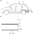
- the noise generated from the road surface during traveling such as tire pattern noise (in a frequency range of 500 to 3000 Hz and simply referred to as pattern noise) is less likely to be reflected and diffused around the lower part of the vehicle body, and the degree of sound intruding into the vehicle Is estimated to be high. Similar problems can occur with electric vehicles.
- noise that was conventionally diffused outside the vehicle is transmitted to a person riding the vehicle.
- these noises are likely to intrude from the bottom of the rear portion of the vehicle and the lower portion of the luggage room (under floor space) where the accommodation space is disposed. Since these noises include noise in the frequency range of 500 to 2000 Hz that people feel uncomfortable, it is required to take measures.
- Patent Document 1 discloses a flexible porous foam molded by foam molding, an introduction passage opened on one surface, and a hollow portion formed at the back of the introduction passage and having a cross-sectional area larger than that of the introduction passage.
- a sound absorbing member is disclosed which has a large number of resonance chambers.
- Patent Document 2 discloses a sound / sound insulation structure including a resin molded body having a plurality of independent blind cavities having openings on the front or back and a sound absorbing member, and having a specific 100 Hz to 10 kHz resonant sound absorption peak frequency. It is done.
- the Helmholtz resonance structure includes an introduction passage opened to the surface and a hollow portion connected to the outside through the introduction passage.
- the air in the introduction passage When the sound reaches the introduction passage of the Helmholtz resonance structure, the air in the introduction passage is pushed by the sound and tries to enter the hollow portion. At this time, since the air is an elastic body, the air in the hollow portion tries to push out the air in the introduction passage. That is, the air in the hollow portion functions as a spring. In this case, the movement of the air in the introduction passage can be expressed as a single vibration movement, and at this frequency, the sound reaching the introduction passage will be resonated and canceled. That is, sound is absorbed.
- the Helmholtz resonance structure can absorb sound of a predetermined frequency, but the sound absorption frequency depends on the volume of the hollow portion and the length and opening area of the introduction passage. Therefore, the sound absorption frequency can be adjusted by adjusting the volume of the hollow portion and the length and opening area of the introduction passage.
- the present invention is an invention made to solve the above-mentioned problems, and an object of the present invention is to provide a sound absorbing member having a sufficiently high sound absorption coefficient.
- the sound absorbing member according to the present invention is a sound absorbing member having a Helmholtz resonance structure including an introduction passage and a hollow portion connected to the outside through the introduction passage,
- the sound absorbing member includes a first layer and a second layer laminated to the first layer,
- the first layer has a first main surface and a second main surface opposite to the first main surface, and
- the second layer has a third main surface facing the second main surface and a fourth main surface opposite to the third main surface
- the first layer has a first through hole which penetrates the second main surface from the first main surface to form the introduction passage
- the second major surface includes a second major surface opening which is an end of the first through hole, and the other second major surface flat portion.
- the third main surface is composed of a third main surface opening that is an end of the hollow portion and the other third main surface flat portion,
- the opening area of the second main surface opening is smaller than the opening area of the third main surface opening,
- a first air layer is formed at least in part between the second major surface flat portion and the third major surface flat portion.
- the sound absorbing member of the present invention is a sound absorbing member in which a first layer forming an introduction passage and a second layer forming a hollow portion are laminated, and has a Helmholtz resonance structure. Therefore, sound of a predetermined frequency can be efficiently absorbed. Furthermore, in the sound absorbing member of the present invention, the first air layer is formed at least in part between the second main surface flat portion of the first layer and the third main surface flat portion of the second layer. . When the sound absorbing member has such a structure, the sound absorption coefficient is improved.
- the second main surface flat portion and the third main surface flat portion may be in contact with each other. Even if part of the second main surface flat portion and the third main surface flat portion are in contact with each other, the first air layer may be formed on a portion between the second main surface flat portion and the third main surface flat portion. If is formed, the sound absorption coefficient is improved.
- At least one of the second main surface flat portion and the third main surface flat portion has a curve or an undulation, and the second main surface flat portion and the third main surface flat portion have a part It may be in contact.
- the first air layer can be formed, and the sound absorption coefficient can be improved.
- the bottom surface of the hollow portion may be in the second layer.
- the second layer has the non-penetrating hole forming the hollow portion.
- the sound absorbing member having such a structure can be manufactured by laminating the first layer and the second layer.
- the third layer having a fifth main surface facing the fourth main surface and a sixth main surface opposite to the fifth main surface is laminated under the second layer.
- the second layer has a second through hole penetrating the fourth main surface from the third main surface to form a side surface of the hollow portion, and the fifth main surface is the The bottom surface of the hollow portion may be formed.
- a through hole that is the side surface of the hollow portion is formed in one layer, and a layer to be the bottom of the hollow portion is stacked thereunder to form a hollow portion.
- the formed sound absorber can be manufactured efficiently. That is, the sound absorbing member having such a structure has high manufacturing efficiency.
- the fourth main surface includes the fourth main surface opening that is an end of the second through hole and the other fourth main surface flat portion, and the fourth main surface is It is desirable that a second air layer be formed at least in part between the flat portion and the fifth main surface. In addition to the first air layer, if the second air layer is present at least in part between the fourth main surface flat portion of the second layer and the fifth main surface of the third layer, the sound absorption efficiency is further improved. .
- the fourth main surface flat portion and the fifth main surface may be in contact with each other. Even if the fourth major surface flat portion and the fifth major surface are in contact with each other, the second air layer is formed on a portion between the fourth major surface flat portion and the fifth major surface. Then, the sound absorption coefficient is improved.
- At least one of the fourth main surface flat portion and the fifth main surface has a curve or an undulation, and the fourth main surface flat portion and the fifth main surface are partially in contact with each other. It is also good.
- the second air layer can be formed, and the sound absorption coefficient can be improved.
- the first main surface includes a first main surface opening that is an end of the first through hole and the other first main surface flat portion, and the first main surface is It is desirable that a fiber layer be further formed on the flat portion.
- the sound absorbing member has a Helmholtz resonance structure, it can absorb sound in a predetermined frequency range, but the width of the frequency range that can absorb sound is not wide, and in particular, it is difficult to sufficiently absorb sound in a high frequency range of 2000 Hz or more. .
- the fiber layer is formed, sound in a high frequency region of 2000 Hz or more can be absorbed.
- the sound absorbing member of the present invention is desirably made of resin and / or fibrous material.
- the resin is preferably an elastomer such as a foamed resin or rubber.
- the sound absorbing member is made of resin, weight reduction can be easily achieved, which is particularly desirable as a component for a vehicle.
- the resin is a foamed resin, the weight thereof can be made lighter, which can contribute to the improvement of the fuel efficiency when it is used as a component for a vehicle.
- a composite material of resin and fiber may be used. As a method of compounding, resin and fiber may be mixed, resin and fiber may be combined in a block shape, and a plate of resin and fiber may be laminated.
- the parts for vehicles of the present invention are characterized by including the sound absorbing member of the present invention. Since the sound absorbing member of the present invention is excellent in sound absorbing performance, it is excellent as a component for a vehicle. As parts for vehicles provided with the sound absorption member of the present invention, a raising member, a partition member, a luggage box, etc. are mentioned.
- An automobile according to the present invention is characterized in that the introduction passage of the sound absorbing member according to the present invention is disposed in the direction of the road surface.
- FIG. 1 is a cross-sectional view schematically showing an example of the sound absorbing member of the present invention.
- FIG. 2 is a cross-sectional view schematically showing an example of the sound absorbing member of the present invention.
- FIG. 3 is a cross-sectional view schematically showing an example of the sound absorbing member of the present invention.
- FIG. 4 is a cross-sectional view schematically showing an example of the sound absorbing member of the present invention.
- FIG. 5 is a cross-sectional view schematically showing an example of the sound absorbing member of the present invention.
- FIG. 6 is a cross-sectional view schematically showing an example of the sound absorbing member of the present invention.
- FIG. 7 is a cross-sectional view schematically showing an example of the sound absorbing member of the present invention.
- FIG. 8 is a cross-sectional view schematically showing an example of the sound absorbing member of the present invention.
- FIG. 9 is a cross-sectional view schematically showing an example of the sound absorbing member of the present invention.
- Fig.10 (a) is explanatory drawing which shows typically an example of the site
- FIG.10 (b) is partial expansion of the area
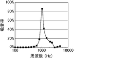
- FIG. 11 is an explanatory view schematically showing a reverberation chamber method sound absorption coefficient with respect to the sound absorption member.
- FIG. 12 is a graph showing the results of a reverberation chamber method sound absorption coefficient test of the sound absorbing member according to the first embodiment of the present invention.
- FIG.10 (a) is explanatory drawing which shows typically an example of the site
- FIG.10 (b) is partial expansion of the area
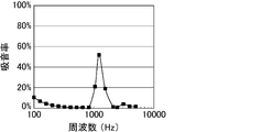
- FIG. 13 is a graph showing the results of a reverberation chamber method sound absorption coefficient test of a sound absorbing member according to a second embodiment of the present invention.
- FIG. 14 is a graph showing the results of a reverberation chamber method sound absorption coefficient test of a sound absorbing member according to Comparative Example 1 of the present invention.
- the sound absorbing member according to the present invention is a sound absorbing member having a Helmholtz resonance structure including an introduction passage and a hollow portion connected to the outside through the introduction passage,
- the sound absorbing member includes a first layer and a second layer laminated to the first layer,
- the first layer has a first main surface and a second main surface opposite to the first main surface, and
- the second layer has a third main surface facing the second main surface and a fourth main surface opposite to the third main surface
- the first layer has a first through hole which penetrates the second main surface from the first main surface to form the introduction passage
- the second major surface includes a second major surface opening which is an end of the first through hole, and the other second major surface flat portion.
- the third main surface is composed of a third main surface opening that is an end of the hollow portion and the other third main surface flat portion,
- the opening area of the second main surface opening is smaller than the opening area of the third main surface opening,
- a first air layer is formed at least in part between the second major surface flat portion and the third major surface flat portion.
- the sound absorbing member of the present invention is a sound absorbing member in which a first layer forming an introduction passage and a second layer forming a hollow portion are laminated, and has a Helmholtz resonance structure. Therefore, sound of a predetermined frequency can be efficiently absorbed. Furthermore, in the sound absorbing member of the present invention, the first air layer is formed at least in part between the second main surface flat portion of the first layer and the third main surface flat portion of the second layer. . When the sound absorbing member has such a structure, the sound absorption coefficient is improved.
- the first air layer may or may not be connected to the hollow portion, but it is more desirable to be connected to the hollow portion.
- the sound absorption coefficient is improved.
- the second major surface flat portion and the third major surface flat portion may be in contact with each other. Even if part of the second main surface flat portion and the third main surface flat portion are in contact with each other, the first air layer may be formed on a portion between the second main surface flat portion and the third main surface flat portion. If is formed, the sound absorption coefficient is improved.
- a spacer may or may not be provided between the second main surface flat portion and the third main surface flat portion in order to form the first air layer.
- the first air layer can be reliably formed on the sound absorbing member of the present invention.
- the absence of the spacer is advantageous because the spring mass effect is not diminished by the spacer.
- the sound absorbing member of the present invention preferably has a total thickness of 10 to 120 mm. More preferably, the thickness of the sound absorbing member is 20 to 100 mm. When the thickness of the sound absorbing member is less than 10 mm, it becomes difficult to form a Helmholtz resonance structure. When the thickness of the sound absorbing member exceeds 120 mm, the sound absorbing member becomes too large, and it becomes difficult to arrange in the desired space.
- the equivalent circle diameter of the opening of the introduction passage (first through hole) is preferably 1 to 30 mm, and more preferably 3 to 25 mm.
- the length of the introduction passage (first through hole) is preferably 1 to 20 mm, and more preferably 3 to 15 mm.
- the volume of the hollow portion is preferably 24 to 329,860 mm 3 , and more preferably 257 to 246,766 mm 3 .
- the sound absorbing member may be composed of two layers of the first layer and the second layer, or may be composed of three layers of the first layer, the second layer and the third layer.
- the case where a sound absorption member consists of two layers, and the case where it consists of the case where a sound absorption member consists of three are divided and demonstrated.
- the sound absorbing member of the present invention is composed of two layers.
- the bottom surface of the hollow portion is in the second layer. That is, in the sound absorbing member of the present invention, the second layer has the non-through hole forming the hollow portion.
- the sound absorbing member of the present invention having a Helmholtz resonance structure can be manufactured by laminating the first layer and the second layer.
- first and second layers as long as the first air layer is formed between the second main surface flat portion of the first layer and the third main surface flat portion of the second layer, It does not matter how they are stacked.
- an adhesive layer may be formed on a portion between the second major surface flat portion and the third major surface flat portion, and the first layer and the second layer may be stacked. Under the present circumstances, you may adhere
- the fitting portion male portion and female portion
- the first through hole is desirably cylindrical, and the cross-sectional shape in the direction perpendicular to the longitudinal direction is preferably a perfect circle.
- the introduction passage has a cylindrical shape. It is advantageous that the introduction passage has a cylindrical shape because the sound absorption characteristics do not have anisotropy.
- the diameter of the bottom surface in the case where the first through hole is cylindrical is preferably 1 to 30 mm. That is, in the sound absorbing member of the present invention, the inner diameter of the introduction passage is preferably 1 to 30 mm.
- the shape of the first through hole is not cylindrical, the diameter of the first through hole is determined as the equivalent circle diameter.
- the equivalent circle diameter is the diameter when the cross-sectional area of the first through hole when cutting the first through hole in the direction perpendicular to the length direction is replaced with a true circle of the same area.
- the diameter may be used as the equivalent circle diameter.
- the arrangement pattern of the first through holes provided in the first layer is a square arrangement in which the first through holes are arranged at the apexes of the squares in a plane in which the squares are continuously arranged vertically and horizontally. It may be a staggered arrangement in which the first through holes are arranged at the apexes of triangles in a plane in which regular triangles are arranged continuously in the vertical and horizontal directions. Among these, a staggered arrangement is desirable. When the arrangement pattern of the first through holes is a staggered arrangement, the adjacent first through holes are likely to be equally spaced, so that the sound absorbing effect is improved. In addition, the strength as the plate material of the first layer can be obtained.
- the plate material constituting the first layer is preferably made of resin.
- the resin is preferably an elastomer such as a foamed resin or rubber. It is particularly desirable as a component for a vehicle because weight reduction can be easily achieved when the plate material constituting the first layer is made of resin. In addition, when the resin is a foamed resin, the weight thereof can be made lighter, which can contribute to the improvement of the fuel efficiency when it is used as a component for a vehicle.
- the plate material constituting the first layer may be a composite material of resin and fiber. As a method of compounding, resin and fiber may be mixed, resin and fiber may be combined in a block shape, and a plate of resin and fiber may be laminated.
- the resin be any of a foamed resin composed of expandable resin particles (beads), a foamed resin having cells, a thermoplastic resin, and a thermosetting resin. It is preferable that the material of the resin has a density of 0.01 to 1 g / cm 3 , and more preferably, the density of the resin is 0.02 to 0.1 g / cm 3 .
- the density of the resin indicates the density of the foamed resin that has been foam-molded. If the density of the resin is within the above range, it is easy to obtain the strength necessary for the sound absorbing member.
- the resin is more preferably a foamed resin comprising expandable resin particles (beads).
- the resin is a foamed resin composed of expandable resin particles (beads)
- the weight of the sound absorbing member can be reduced while maintaining the strength, which can contribute to the improvement of fuel efficiency when used for parts for vehicles .
- the foamed resin is obtained by foaming and molding expandable resin particles.
- the expandable resin particles (beads) used as the plate material constituting the first layer are particles containing a foaming agent inside the resin particles, and known materials are suitably used.
- the resin component constituting the expandable resin particles include olefin resins such as polyethylene and polypropylene, and styrene resins such as polystyrene.
- a styrene resin a copolymer obtained by copolymerizing a styrene homopolymer, styrene, and a monomer (or its derivative) copolymerizable with styrene is mentioned.
- the styrene copolymer may be any of a block copolymer, a random copolymer, and a graft copolymer.
- the blowing agent include hydrocarbons such as propane, butane and pentane.
- the expandable resin particles used as a plate material constituting the first layer may be, if necessary, a flame retardant, a flame retardant aid, a processing aid, a filler, an antioxidant, light resistance
- Known additives such as a sex stabilizer, an antistatic agent and a colorant may be added.
- a sex stabilizer As an example of use of an additive, if a black thing is used for a coloring agent, a stain will become inconspicuous.
- Flame retardants include hydrated metal flame retardants such as aluminum hydroxide and magnesium hydroxide, phosphoric acid flame retardants such as red phosphorus and ammonium phosphate, tetrabromobisphenol A (TABB), brominated polystyrene, chlorinated paraffin And halogen-based flame retardants, ammonium carbonate, nitrogen-based flame retardants such as melamine cyanurate, and the like.
- phosphoric acid flame retardants such as red phosphorus and ammonium phosphate, tetrabromobisphenol A (TABB), brominated polystyrene, chlorinated paraffin And halogen-based flame retardants, ammonium carbonate, nitrogen-based flame retardants such as melamine cyanurate, and the like.
- TABB tetrabromobisphenol A
- brominated polystyrene chlorinated paraffin And halogen-based flame retardants
- ammonium carbonate such as melamine cyanurate
- antioxidant examples include alkylphenols, alkylene bisphenols, alkylphenol thioethers, ⁇ , ⁇ -thiopropionic acid esters, organic phosphites and phenol-nickel complexes.
- light fastness stabilizer examples include benzotriazole-based UV absorbers and hindered amine-based stabilizers.
- antistatic agent examples include low molecular weight antistatic agents such as fatty acid ester compounds, aliphatic ethanolamine compounds and aliphatic ethanolamide compounds, and high molecular weight antistatic agents.
- a coloring agent a dye, a pigment, etc. are mentioned.
- the average particle diameter of the expandable resin particles used as the plate material constituting the first layer is preferably 300 ⁇ m to 2400 ⁇ m, and more preferably 800 ⁇ m to 2000 ⁇ m.
- the expansion ratio of the expandable resin particles is desirably 10 to 60 times. By setting the expansion ratio to 10 to 60 times, the density of the resin can be easily adjusted to the range of 0.02 to 0.1 g / cm 3 . On the other hand, if the expansion ratio is less than 10 times, the sound absorbing member may be too hard or too heavy. When the expansion ratio exceeds 60 times, the strength of the sound absorbing member may be insufficient.
- polyurethane or the like can be used as the foamed resin used as the plate material constituting the first layer.
- a foaming agent and the like By mixing polyurethane as a main ingredient, a foaming agent and the like, and foaming and forming the mixture, a foamed resin having cells can be obtained, whereby a plate material can be manufactured.
- the resin used as the plate material constituting the first layer may be a thermoplastic resin or a thermosetting resin.
- a thermoplastic resin used as a plate material constituting the first layer polypropylene resin, polyethylene resin, polyester resin (such as nylon 6-6), polystyrene resin, etc. can be used.
- a sound absorbing member can be manufactured by molding a thermoplastic resin as a resin pellet, heating the resin pellet, and performing a molding process such as injection molding and extrusion molding.
- epoxy resin, phenol resin, melamine resin, urea resin, polyurethane, polyurea, polyamide, polyacrylamide, etc. may be used as the thermosetting resin used as the plate material constituting the first layer. it can.
- the sound absorbing member can be manufactured by preheating the thermosetting resin, placing it in a mold, pressurizing it, raising the temperature of the mold and curing it.
- the plate material constituting the first layer in addition to the resin, a material such as an inorganic material or a metal material may be used.
- the thickness of the plate constituting the first layer is preferably 1 to 20 mm.
- the thickness of the plate is the length of the first through hole and the length of the introduction passage. That is, the length of the first through hole is preferably 1 to 20 mm. Further, the length of the introduction passage is also preferably 1 to 20 mm.
- the first main surface is composed of the first main surface opening which is the end of the first through hole and the other first main surface flat portion, but the first main surface is flat.
- a fiber layer is further formed on the part.
- the material constituting the fiber layer is preferably selected from natural fibers, synthetic resin fibers, and inorganic fibers.
- Natural fibers include vegetable fibers, animal fibers and mineral fibers.
- synthetic resin fibers include polyamide resins (nylon etc.), polyester resins (polyethylene terephthalate (PET), polyethylene naphthalate (PEN) etc.), acrylic resins, polyvinyl alcohol resins, polyolefin resins (polyethylene, polypropylene etc.) etc. It can be mentioned.
- As the inorganic fibers alumina fibers, silica fibers, silica-alumina fibers, glass fibers, carbon fibers, potassium titanate fibers, rock wool and the like can be mentioned.
- the fiber layer may be formed as a felt or non-woven fabric.
- the thickness of the fiber layer is preferably 1 to 20 mm.
- air vibration occurs in the space, and sound in a high frequency region can be absorbed.
- the first major surface flat portion and the fiber layer may or may not be bonded by an adhesive layer.
- the second layer is a plate having a non-through hole, and is stacked with the first layer.
- the non-through hole of the second layer is connected to the first through hole of the first layer, ie, the introduction passage, so that the non-through hole is connected to the outside to form a Helmholtz resonance structure.
- the shape of the non-through hole provided in the second layer in the sound absorbing member of the present invention is preferably cylindrical, and the cross-sectional shape in the direction perpendicular to the longitudinal direction is preferably a perfect circle.
- the height is preferably 1 to 20 mm, and more preferably 3 to 15 mm.
- the diameter of the non-through hole is determined as a circle equivalent diameter.
- the equivalent circle diameter is a diameter when the cross-sectional area of the non-through hole when cutting the non-through hole in the direction perpendicular to the length direction is replaced with a true circle of the same area.
- the cross-sectional shape of the non-through hole is a perfect circle, the diameter may be used as the equivalent circle diameter.
- the arrangement pattern of non-through holes provided in the second layer may be a tetragonal arrangement in which non-through holes are disposed at the apexes of squares in a plane in which squares are continuously arranged vertically and horizontally. It may be a staggered arrangement in which non-through holes are arranged at the apexes of triangles in a plane in which regular triangles are arranged continuously in the vertical and horizontal directions. Among these, a staggered arrangement is desirable. When the arrangement pattern of the non-through holes is a staggered arrangement, the adjacent non-through holes are likely to be equally spaced, so that the sound absorbing effect is improved. In addition, the strength as the plate material of the second layer can be obtained.
- the positional relationship between the introduction passage and the non-through hole may be such that the non-through hole is connected to the outside through the introduction passage, and the center of the introduction passage and the non-through hole (perpendicular to the thickness direction The center in the cross-sectional shape when cutting in the same direction may or may not coincide.
- the non-through holes in the second layer are preferably formed by machining the plate material, and cutting with an end mill or processing with a hot wire is preferably used.
- a foamed resin comprising expandable resin particles (beads) as a plate material, a plate material having non-through holes can also be obtained by performing foam molding in a mold having protrusions corresponding to the shape of non-through holes. It can be made.
- the plate material constituting the second layer is desirably made of a resin and / or a fibrous material.
- the resin is preferably an elastomer such as a foamed resin or rubber. It is particularly desirable as a vehicle part because weight reduction can be easily achieved when the plate material constituting the second layer is made of resin. In addition, when the resin is a foamed resin, the weight thereof can be made lighter, which can contribute to the improvement of the fuel efficiency when it is used as a component for a vehicle.
- the plate material constituting the second layer may be a composite material of resin and fiber. As a method of compounding, resin and fiber may be mixed, resin and fiber may be combined in a block shape, and a plate of resin and fiber may be laminated.
- the resin be any of a foamed resin composed of expandable resin particles (beads), a foamed resin having cells, a thermoplastic resin, and a thermosetting resin. It is preferable that the material of the resin has a density of 0.01 to 1 g / cm 3 , and more preferably, the density of the resin is 0.02 to 0.1 g / cm 3 .
- the density of the resin indicates the density of the foamed resin that has been foam-molded. If the density of the resin is within the above range, it is easy to obtain the strength necessary for the sound absorbing member.
- the resin is more preferably a foamed resin comprising expandable resin particles (beads).
- the resin is a foamed resin composed of expandable resin particles (beads)
- the weight of the sound absorbing member can be reduced while maintaining the strength, which can contribute to the improvement of fuel efficiency when used for parts for vehicles .
- the foamed resin is obtained by foaming and molding expandable resin particles.
- a plate material which is a foamed resin comprising expandable resin particles (beads) does not have communicating pores.
- the expandable resin particles (beads) used as a plate material constituting the second layer are particles containing a foaming agent inside the resin particles, and known materials are suitably used.
- the resin component constituting the expandable resin particles include olefin resins such as polyethylene and polypropylene, and styrene resins such as polystyrene.
- a styrene resin a copolymer obtained by copolymerizing a styrene homopolymer, styrene, and a monomer (or its derivative) copolymerizable with styrene is mentioned.
- the styrene copolymer may be any of a block copolymer, a random copolymer, and a graft copolymer.
- the blowing agent include hydrocarbons such as propane, butane and pentane.
- the expandable resin particles used as the plate material constituting the second layer may be, if necessary, a flame retardant, a flame retardant aid, a processing aid, a filler, an antioxidant, light resistance
- Known additives such as a sex stabilizer, an antistatic agent and a colorant may be added.
- a black thing is used for a coloring agent, a stain will become inconspicuous.
- Flame retardants include hydrated metal flame retardants such as aluminum hydroxide and magnesium hydroxide, phosphoric acid flame retardants such as red phosphorus and ammonium phosphate, tetrabromobisphenol A (TABB), brominated polystyrene, chlorinated paraffin And halogen-based flame retardants, ammonium carbonate, nitrogen-based flame retardants such as melamine cyanurate, and the like.
- phosphoric acid flame retardants such as red phosphorus and ammonium phosphate, tetrabromobisphenol A (TABB), brominated polystyrene, chlorinated paraffin And halogen-based flame retardants, ammonium carbonate, nitrogen-based flame retardants such as melamine cyanurate, and the like.
- TABB tetrabromobisphenol A
- brominated polystyrene chlorinated paraffin And halogen-based flame retardants
- ammonium carbonate such as melamine cyanurate
- antioxidant examples include alkylphenols, alkylene bisphenols, alkylphenol thioethers, ⁇ , ⁇ -thiopropionic acid esters, organic phosphites and phenol-nickel complexes.
- light fastness stabilizer examples include benzotriazole-based UV absorbers and hindered amine-based stabilizers.
- antistatic agent examples include low molecular weight antistatic agents such as fatty acid ester compounds, aliphatic ethanolamine compounds and aliphatic ethanolamide compounds, and high molecular weight antistatic agents.
- a coloring agent a dye, a pigment, etc. are mentioned.
- the average particle diameter of the expandable resin particles used as a plate material constituting the second layer is preferably 300 ⁇ m to 2400 ⁇ m, and more preferably 800 ⁇ m to 2000 ⁇ m.
- the expansion ratio of the expandable resin particles is desirably 10 to 60 times. By setting the expansion ratio to 10 to 60 times, the density of the resin can be easily adjusted to the range of 0.02 to 0.1 g / cm 3 . On the other hand, if the expansion ratio is less than 10 times, the sound absorbing member may be too hard or too heavy. When the expansion ratio exceeds 60 times, the strength of the sound absorbing member may be insufficient.
- polyurethane or the like can be used as the foamed resin used as the plate material constituting the second layer.
- a foaming agent and the like By mixing polyurethane as a main ingredient, a foaming agent and the like, and foaming and forming the mixture, a foamed resin having cells can be obtained, whereby a plate material can be manufactured.
- the resin used as the plate material constituting the second layer may be a thermoplastic resin or a thermosetting resin.
- a thermoplastic resin used as a plate material constituting the second layer polypropylene resin, polyethylene resin, polyester resin (such as nylon 6-6), polystyrene resin, etc. can be used.
- a sound absorbing member can be manufactured by molding a thermoplastic resin as a resin pellet, heating the resin pellet, and performing a molding process such as injection molding and extrusion molding.
- epoxy resin, phenol resin, melamine resin, urea resin, polyurethane, polyurea, polyamide, polyacrylamide, etc. may be used as the thermosetting resin used as the plate material constituting the second layer. it can.
- the sound absorbing member can be manufactured by preheating the thermosetting resin, placing it in a mold, pressurizing it, raising the temperature of the mold and curing it.
- the fibers used as the plate material constituting the second layer are preferably organic fibers or inorganic fibers, and polyester, polyamide, acetate or the like can be used as the organic fibers.
- the inorganic fibers alumina, silica and mullite fibers are desirable. It is desirable to bond the fibers together with the binder into a felt.
- the plate material constituting the second layer in addition to the resin, a material such as an inorganic material or a metal material may be used.
- the thickness of the plate constituting the second layer is preferably 10 to 120 mm. In addition, it is further desirable that the distance be 20 to 100 mm.
- the first layer and the second layer may be bonded by an adhesive.
- the upper and lower layers may be connected by providing a female portion and a male portion in the upper and lower layer contact portions and fitting them together.
- FIG. 1 is a cross-sectional view schematically showing an example of the sound absorbing member of the present invention.
- FIG. 2 is a cross-sectional view schematically showing an example of the sound absorbing member of the present invention.
- FIG. 3 is a cross-sectional view schematically showing an example of the sound absorbing member of the present invention.
- FIG. 4 is a cross-sectional view schematically showing an example of the sound absorbing member of the present invention.
- FIG. 5 is a cross-sectional view schematically showing an example of the sound absorbing member of the present invention.
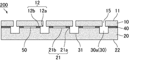
- the sound absorbing member of the present invention may be configured as shown in FIG. That is, the sound absorbing member 100 which is an example of the sound absorbing member of the present invention includes the first layer 10 and the second layer 20 laminated on the first layer 10.
- the first layer 10 has a first major surface 11 and a second major surface 12 opposite to the first major surface 11.
- the first layer 10 has a first through hole 15 which penetrates the second major surface 12 from the first major surface 11 to form an introduction passage.
- the second major surface 12 is composed of a second major surface opening 12 a which is an end portion of the first through hole 15, and the other second major surface flat portion 12 b.
- the second layer 20 has a third major surface 21 facing the second major surface 12 and a fourth major surface 22 opposite to the third major surface 21.
- the non-through holes 30a are formed on the third main surface 21 side.
- the third major surface 21 is composed of a third major surface opening 21a which is an end portion of the non-through hole 30a, and the other third major surface flat portion 21b.
- the opening area of the second main surface opening 12a is smaller than the opening area of the third main surface opening 21a.
- the first layer 10 and the second layer 20 are partially bonded by the adhesive layer 40, and the non-through holes 30a form the hollow portion 30, and the hollow portion 30 is formed.
- the bottom surface 31 of the is to be in the second layer 20.
- a first air layer 50 is formed between the second major surface flat portion 12 b and the third major surface flat portion 21 b.
- the first air layer 50 is connected to the hollow portion 30.
- the sound absorbing member of the present invention may be configured as shown in FIG. That is, the sound absorbing member 200 which is an example of the sound absorbing member of the present invention includes the first layer 10 and the second layer 20 laminated on the first layer 10.
- the first layer 10 has a first major surface 11 and a second major surface 12 opposite to the first major surface 11.
- the first layer 10 has a first through hole 15 which penetrates the second major surface 12 from the first major surface 11 to form an introduction passage.
- the second major surface 12 is composed of a second major surface opening 12 a which is an end portion of the first through hole 15, and the other second major surface flat portion 12 b.
- the second layer 20 has a third major surface 21 facing the second major surface 12 and a fourth major surface 22 opposite to the third major surface 21.
- the non-through holes 30a are formed on the third main surface 21 side.
- the third major surface 21 is composed of a third major surface opening 21a which is an end portion of the non-through hole 30a, and the other third major surface flat portion 21b.
- the opening area of the second main surface opening 12a is smaller than the opening area of the third main surface opening 21a.
- a part of the first layer 10 and the second layer 20 is adhered by the adhesive layer 40, and the non-through hole 30a forms the hollow portion 30, and the hollow portion 30 is formed.
- the bottom surface 31 of the is to be in the second layer 20.
- a first air layer 50 is formed between the second major surface flat portion 12 b and the third major surface flat portion 21 b.
- the first air layer 50 is not connected to the hollow portion 30.
- the sound absorbing member of the present invention may be configured as shown in FIG. That is, the sound absorbing member 300 which is an example of the sound absorbing member of the present invention includes the first layer 10 and the second layer 20 laminated on the first layer 10.
- the first layer 10 has a first major surface 11 and a second major surface 12 opposite to the first major surface 11.
- the first layer 10 has a first through hole 15 which penetrates the second major surface 12 from the first major surface 11 to form an introduction passage.
- the second major surface 12 is composed of a second major surface opening 12 a which is an end portion of the first through hole 15, and the other second major surface flat portion 12 b.
- the second layer 20 has a third major surface 21 facing the second major surface 12 and a fourth major surface 22 opposite to the third major surface 21.
- the non-through holes 30a are formed on the third main surface 21 side.
- the third major surface 21 is composed of a third major surface opening 21a which is an end portion of the non-through hole 30a, and the other third major surface flat portion 21b.
- the opening area of the second main surface opening 12a is smaller than the opening area of the third main surface opening 21a.
- the edge portion of the second major surface flat portion 12b and the edge portion of the third major surface flat portion 21b are bonded by the adhesive layer 40.
- the non-through hole 30 a forms the hollow portion 30, and the bottom surface 31 of the hollow portion 30 is in the second layer 20.
- a first air layer 50 is formed between the second major surface flat portion 12 b and the third major surface flat portion 21 b, and the first air layer 50 is connected to the hollow portion 30. .
- the sound absorption coefficient is improved by the spring mass effect.
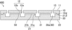
- the sound absorbing member of the present invention may be configured as shown in FIG. That is, the sound absorbing member 400 which is an example of the sound absorbing member of the present invention includes the first layer 10 and the second layer 20 laminated on the first layer 10.
- the first layer 10 has a first major surface 11 and a second major surface 12 opposite to the first major surface 11.
- the first layer 10 has a first through hole 15 which penetrates the second major surface 12 from the first major surface 11 to form an introduction passage.
- the second major surface 12 is composed of a second major surface opening 12 a which is an end portion of the first through hole 15, and the other second major surface flat portion 12 b.
- the second layer 20 has a third major surface 21 facing the second major surface 12 and a fourth major surface 22 opposite to the third major surface 21.
- the non-through holes 30a are formed on the third main surface 21 side.
- the third major surface 21 is composed of a third major surface opening 21a which is an end portion of the non-through hole 30a, and the other third major surface flat portion 21b.
- the opening area of the second main surface opening 12a is smaller than the opening area of the third main surface opening 21a.
- the male portion 12 ⁇ is formed in the second major surface flat portion 12b
- the female portion 21 ⁇ is formed in the third major surface flat portion 21b.
- the layer 10 and the second layer 20 are connected.
- the non-through hole 30a forms the hollow portion 30, and the bottom surface 31 of the hollow portion 30 is in the second layer 20.
- a first air layer 50 is formed between the second major surface flat portion 12 b and the third major surface flat portion 21 b.
- the first air layer 50 is connected to the hollow portion 30.
- the sound absorbing member of the present invention may be configured as shown in FIG. That is, the sound absorbing member 500 which is an example of the sound absorbing member of the present invention includes the first layer 10 and the second layer 20 laminated on the first layer 10.
- the first layer 10 has a first major surface 11 and a second major surface 12 opposite to the first major surface 11.
- the first layer 10 has a first through hole 15 which penetrates the second major surface 12 from the first major surface 11 to form an introduction passage.
- the second major surface 12 is composed of a second major surface opening 12 a which is an end portion of the first through hole 15, and the other second major surface flat portion 12 b.
- the second layer 20 has a third major surface 21 facing the second major surface 12 and a fourth major surface 22 opposite to the third major surface 21.
- the non-through holes 30a are formed on the third main surface 21 side.
- the third major surface 21 is composed of a third major surface opening 21a which is an end portion of the non-through hole 30a, and the other third major surface flat portion 21b.
- the opening area of the second main surface opening 12a is smaller than the opening area of the third main surface opening 21a.
- the second main surface flat portion 12b and the third main surface flat portion 21b are bonded by an adhesive at the end.
- the non-through holes 30a form the hollow portion 30, and the bottom surface 31 of the hollow portion 30 is in the second layer 20.
- the first layer 10 is curved to be convex upward
- the first air layer 50 is formed between the second major surface flat portion 12 b and the third major surface flat portion 21 b. . That is, the second major surface flat portion 12b is curved so as to be convex upward.
- the first air layer 50 is connected to the hollow portion 30. By forming the first air layer 50, the sound absorption coefficient is improved by the spring mass effect.
- the sound absorbing member of the present invention can be manufactured by laminating a first layer in which a first through hole is provided in a plate material and a second layer in which a hollow portion is provided.
- the method for producing the sound absorbing member of the present invention is Producing an upper layer which is a plate material having a columnar first through hole serving as an introduction passage; Producing a second layer which is a plate material having a hollow portion; And laminating the first layer and the second layer such that a first air layer is formed between the second major surface flat portion of the first layer and the third major surface flat portion of the second layer.
- a plate material of a predetermined thickness made of a material such as a resin that can be used as a plate material is prepared.
- the first layer can be produced by forming the first through hole with a means such as punching, drill or laser for a plate material having no through hole.
- a foamed resin comprising expandable resin particles (beads) as a plate material
- the plate is also provided with a protrusion for forming the first through hole in the mold to foam the expandable resin particles.
- a first layer provided with a first through hole can be manufactured.
- a plate material of a predetermined thickness made of a material such as a resin that can be used as a plate material is prepared.
- the second layer can be manufactured by forming a non-through hole which becomes a hollow portion by the middle of the thickness direction of a plate material having no through hole.
- the diameter of the non-through hole is made larger than the diameter of the first through hole.
- the non-through holes are preferably formed by machining, and cutting with an end mill or processing with a hot wire is preferably used.
- a plate material having non-through holes can also be obtained by performing foam molding in a mold having protrusions corresponding to the shape of non-through holes. It can be made.
- the fitting portion male portion or the male portion or the second layer
- female part may be formed.
- a sheet-like adhesive is prepared in accordance with the shape and position of the non-through holes (hollow part) of the second layer. Do. At this time, the sheet-like adhesive layer is processed so that the first air layer is formed between the second main surface flat portion of the first layer and the third main surface flat portion of the second layer. .
- the first layer and the second layer can be bonded by the adhesive layer by exerting the adhesive force of the adhesive by sandwiching the first layer and the second layer.
- the Helmholtz resonance structure is formed by aligning the positions of the first through holes of the first layer and the hollow portions (non-through holes) of the second layer. Let's do it.
- An adhesive is applied according to the shape and position of the non-through holes (hollow part) of the second layer, and the first layer and the second layer are laminated to exert the adhesive force of the adhesive, thereby forming the first layer
- the second layer can be adhered by an adhesive layer.
- the conditions for exerting the adhesive strength of the adhesive conditions in accordance with the adhesive characteristics of the adhesive may be used.
- the sound absorbing member of the present invention manufactures the sound absorbing member of the present invention having a Helmholtz resonance structure by laminating the first layer forming the introduction passage, and the second layer and the third layer forming the hollow portion. can do.
- first and second layers as long as the first air layer is formed between the second main surface flat portion of the first layer and the third main surface flat portion of the second layer, It does not matter how they are stacked.
- an adhesive layer may be formed on a portion between the second major surface flat portion and the third major surface flat portion, and the first layer and the second layer may be stacked. Under the present circumstances, you may adhere
- the fitting portion male portion and female portion
- the first through hole is desirably cylindrical, and the cross-sectional shape in the direction perpendicular to the longitudinal direction is preferably a perfect circle.
- the introduction passage has a cylindrical shape. It is advantageous that the introduction passage has a cylindrical shape because the sound absorption characteristics do not have anisotropy.
- the diameter of the bottom surface in the case where the first through hole is cylindrical is preferably 1 to 30 mm. That is, in the sound absorbing member of the present invention, the inner diameter of the introduction passage is preferably 1 to 30 mm.
- the shape of the first through hole is not cylindrical, the diameter of the first through hole is determined as the equivalent circle diameter.
- the equivalent circle diameter is the diameter when the cross-sectional area of the first through hole when cutting the first through hole in the direction perpendicular to the length direction is replaced with a true circle of the same area.
- the diameter may be used as the equivalent circle diameter.
- the arrangement pattern of the first through holes provided in the first layer is a square arrangement in which the first through holes are arranged at the apexes of the squares in a plane in which the squares are continuously arranged vertically and horizontally. It may be a staggered arrangement in which the first through holes are arranged at the apexes of triangles in a plane in which regular triangles are arranged continuously in the vertical and horizontal directions. Among these, a staggered arrangement is desirable. When the arrangement pattern of the first through holes is a staggered arrangement, the adjacent first through holes are likely to be equally spaced, so that the sound absorbing effect is improved. In addition, the strength as the plate material of the first layer can be obtained.
- the plate material constituting the first layer is preferably made of resin.
- the resin is preferably an elastomer such as a foamed resin or rubber. It is particularly desirable as a component for a vehicle because weight reduction can be easily achieved when the plate material constituting the first layer is made of resin. In addition, when the resin is a foamed resin, the weight thereof can be made lighter, which can contribute to the improvement of the fuel efficiency when it is used as a component for a vehicle.
- the plate material constituting the first layer may be a composite material of resin and fiber. As a method of compounding, resin and fiber may be mixed, resin and fiber may be combined in a block shape, and a plate of resin and fiber may be laminated.
- the resin be any of a foamed resin composed of expandable resin particles (beads), a foamed resin having cells, a thermoplastic resin, and a thermosetting resin. It is preferable that the material of the resin has a density of 0.01 to 1 g / cm 3 , and more preferably, the density of the resin is 0.02 to 0.1 g / cm 3 .
- the density of the resin indicates the density of the foamed resin that has been foam-molded. If the density of the resin is within the above range, it is easy to obtain the strength necessary for the sound absorbing member.
- the resin is more preferably a foamed resin comprising expandable resin particles (beads).
- the resin is a foamed resin composed of expandable resin particles (beads)
- the weight of the sound absorbing member can be reduced while maintaining the strength, which can contribute to the improvement of fuel efficiency when used for parts for vehicles .
- the foamed resin is obtained by foaming and molding expandable resin particles.
- the expandable resin particles (beads) used as the plate material constituting the first layer are particles containing a foaming agent inside the resin particles, and known materials are suitably used.
- the resin component constituting the expandable resin particles include olefin resins such as polyethylene and polypropylene, and styrene resins such as polystyrene.
- a styrene resin a copolymer obtained by copolymerizing a styrene homopolymer, styrene, and a monomer (or its derivative) copolymerizable with styrene is mentioned.
- the styrene copolymer may be any of a block copolymer, a random copolymer, and a graft copolymer.
- the blowing agent include hydrocarbons such as propane, butane and pentane.
- the expandable resin particles used as a plate material constituting the first layer may be, if necessary, a flame retardant, a flame retardant aid, a processing aid, a filler, an antioxidant, light resistance
- Known additives such as a sex stabilizer, an antistatic agent and a colorant may be added.
- a sex stabilizer As an example of use of an additive, if a black thing is used for a coloring agent, a stain will become inconspicuous.
- Flame retardants include hydrated metal flame retardants such as aluminum hydroxide and magnesium hydroxide, phosphoric acid flame retardants such as red phosphorus and ammonium phosphate, tetrabromobisphenol A (TABB), brominated polystyrene, chlorinated paraffin And halogen-based flame retardants, ammonium carbonate, nitrogen-based flame retardants such as melamine cyanurate, and the like.
- phosphoric acid flame retardants such as red phosphorus and ammonium phosphate, tetrabromobisphenol A (TABB), brominated polystyrene, chlorinated paraffin And halogen-based flame retardants, ammonium carbonate, nitrogen-based flame retardants such as melamine cyanurate, and the like.
- TABB tetrabromobisphenol A
- brominated polystyrene chlorinated paraffin And halogen-based flame retardants
- ammonium carbonate such as melamine cyanurate
- antioxidant examples include alkylphenols, alkylene bisphenols, alkylphenol thioethers, ⁇ , ⁇ -thiopropionic acid esters, organic phosphites and phenol-nickel complexes.
- light fastness stabilizer examples include benzotriazole-based UV absorbers and hindered amine-based stabilizers.
- antistatic agent examples include low molecular weight antistatic agents such as fatty acid ester compounds, aliphatic ethanolamine compounds and aliphatic ethanolamide compounds, and high molecular weight antistatic agents.
- a coloring agent a dye, a pigment, etc. are mentioned.
- the average particle diameter of the expandable resin particles used as the plate material constituting the first layer is preferably 300 ⁇ m to 2400 ⁇ m, and more preferably 800 ⁇ m to 2000 ⁇ m.
- the expansion ratio of the expandable resin particles is desirably 10 to 60 times. By setting the expansion ratio to 10 to 60 times, the density of the resin can be easily adjusted to the range of 0.02 to 0.1 g / cm 3 . On the other hand, if the expansion ratio is less than 10 times, the sound absorbing member may be too hard or too heavy. When the expansion ratio exceeds 60 times, the strength of the sound absorbing member may be insufficient.
- polyurethane or the like can be used as the foamed resin used as the plate material constituting the first layer.
- a foaming agent and the like By mixing polyurethane as a main ingredient, a foaming agent and the like, and foaming and forming the mixture, a foamed resin having cells can be obtained, whereby a plate material can be manufactured.
- the resin used as the plate material constituting the first layer may be a thermoplastic resin or a thermosetting resin.
- a thermoplastic resin used as a plate material constituting the first layer polypropylene resin, polyethylene resin, polyester resin (such as nylon 6-6), polystyrene resin, etc. can be used.
- a sound absorbing member can be manufactured by molding a thermoplastic resin as a resin pellet, heating the resin pellet, and performing a molding process such as injection molding and extrusion molding.
- epoxy resin, phenol resin, melamine resin, urea resin, polyurethane, polyurea, polyamide, polyacrylamide, etc. may be used as the thermosetting resin used as the plate material constituting the first layer. it can.
- the sound absorbing member can be manufactured by preheating the thermosetting resin, placing it in a mold, pressurizing it, raising the temperature of the mold and curing it.
- the plate material constituting the first layer in addition to the resin, a material such as an inorganic material or a metal material may be used.
- the thickness of the plate constituting the first layer is preferably 1 to 20 mm.
- the thickness of the plate is the length of the first through hole and the length of the introduction passage. That is, the length of the first through hole is preferably 1 to 20 mm. Further, the length of the introduction passage is also preferably 1 to 20 mm.
- the first main surface is composed of the first main surface opening which is the end of the first through hole and the other first main surface flat portion, but the first main surface is flat.
- a fiber layer is further formed on the part.
- the material constituting the fiber layer is preferably selected from natural fibers, synthetic resin fibers, and inorganic fibers.
- Natural fibers include vegetable fibers, animal fibers and mineral fibers.
- synthetic resin fibers include polyamide resins (nylon etc.), polyester resins (polyethylene terephthalate (PET), polyethylene naphthalate (PEN) etc.), acrylic resins, polyvinyl alcohol resins, polyolefin resins (polyethylene, polypropylene etc.) etc. It can be mentioned.
- As the inorganic fibers alumina fibers, silica fibers, silica-alumina fibers, glass fibers, carbon fibers, potassium titanate fibers, rock wool and the like can be mentioned.
- the fiber layer may be formed as a felt or non-woven fabric.
- the thickness of the fiber layer is preferably 1 to 20 mm.
- air vibration occurs in the space, and sound in a high frequency region can be absorbed.
- the first major surface flat portion and the fiber layer may or may not be bonded by an adhesive layer.
- the second layer is a plate material provided with a columnar second through hole having a larger opening diameter than the first through hole
- the third layer is a plate material not provided with the through hole May be A hollow portion can be formed by laminating the second layer and the third layer.
- the second layer is made of a plate material, and the plate material is provided with a second through hole.
- the second through hole is in a columnar shape, and is a portion having a columnar space only with air. It is preferable that the diameter of the through hole is constant from the inlet side to the outlet side in the thickness direction of the plate material. That is, it is preferable not to include a form in which gas passes in the thickness direction but the other side can not be seen (does not penetrate) in top view in the thickness direction, such as communicating pores in a porous material.
- the second through hole is preferably a through hole formed by machining a plate material having no through hole, and punching by a punching, a drill, a laser or the like is suitably used.
- the second through hole provided in the second layer is preferably cylindrical, and the cross-sectional shape in the direction perpendicular to the longitudinal direction is preferably a perfect circle.
- the hollow portion has a cylindrical shape. It is advantageous that the hollow portion has a cylindrical shape because the sound absorption characteristics do not have anisotropy.
- the diameter (opening diameter) of the bottom surface when the second through hole is cylindrical is preferably 4 to 171 mm, preferably 10 mm or more, and 150 mm or less. preferable.
- the arrangement pattern of the second through holes provided in the second layer is a square arrangement in which the second through holes are disposed at the apexes of the squares in a plane in which the squares are continuously arranged in the vertical and horizontal directions. It may be a staggered arrangement in which second through holes are arranged at the apexes of triangles in a plane in which regular triangles are arranged continuously in the vertical and horizontal directions. Among these, a staggered arrangement is desirable. When the arrangement pattern of the second through holes is a staggered arrangement, the hollow portions formed by the adjacent second through holes are likely to be equally spaced, so that the sound absorbing effect is improved. In addition, the strength as the plate material of the second layer can be obtained.
- the thickness of the plate constituting the second layer is preferably 1 to 20 mm, and more preferably 3 to 15 mm.
- the thickness of the plate material constituting the second layer is the length of the second through hole, and the height of the hollow portion. That is, the length of the second through hole is preferably 1 to 20 mm.
- the third layer is made of a plate material and no through hole is provided. By overlapping the second layer and the third layer, a hollow portion is formed by the second through hole of the second layer and the third layer.
- the thickness of the plate constituting the third layer is preferably 1 to 20 mm.
- the end of the second through hole is taken as the fourth main surface opening, and the other part is taken as the fourth main surface flat part.
- the surface of the second layer facing the fourth main surface is taken as the fifth main surface of the third layer, and the surface opposite to the fifth main surface is taken as the sixth main surface of the third layer.
- the second air layer may or may not be connected to the hollow portion, but it is more desirable to be connected to the hollow portion.
- the sound absorption coefficient is improved.
- the second and third layers may be stacked in any manner.
- an adhesive layer may be formed on a part between the fourth major surface flat portion and the fifth major surface, and the second layer and the third layer may be stacked.
- the second layer and the third layer may be bonded only at the end of the second layer and the third layer.
- a fitting portion male portion and female portion
- the fourth main surface flat portion and the fifth main surface may be in contact with each other. Even if the fourth major surface flat portion and the fifth major surface are in contact with each other, the second air layer is formed on a portion between the fourth major surface flat portion and the fifth major surface. Then, the sound absorption coefficient is improved.
- a spacer may or may not be provided between the flat portion of the fourth main surface and the fifth main surface to form the second air layer.
- the second air layer can be reliably formed on the sound absorbing member of the present invention.
- the absence of the spacer is advantageous because the spring mass effect is not diminished by the spacer.
- the plate material constituting the second layer and the third layer be made of a resin and / or a fibrous material.
- the resin is preferably an elastomer such as a foamed resin or rubber.
- plate material which comprises a 2nd layer and a 3rd layer is the same material, it may be a different material.
- the resin is preferably a foamed resin. It is particularly desirable as a vehicle part because weight reduction can be easily achieved when the plate material constituting the second layer and the third layer is made of resin.
- the plate material constituting the second layer and the third layer may be a composite material of resin and fiber.
- resin and fiber may be mixed, resin and fiber may be combined in a block shape, and a plate of resin and fiber may be laminated.
- the resin be any of a foamed resin composed of expandable resin particles (beads), a foamed resin having cells, a thermoplastic resin, and a thermosetting resin. It is preferable that the material of the resin has a density of 0.01 to 1 g / cm 3 , and more preferably, the density of the resin is 0.02 to 0.1 g / cm 3 .
- the density of the resin indicates the density of the foamed resin that has been foam-molded. If the density of the resin is within the above range, it is easy to obtain the strength necessary for the sound absorbing member.
- the resin is more preferably a foamed resin comprising expandable resin particles (beads).
- the resin is a foamed resin composed of expandable resin particles (beads)
- the weight of the sound absorbing member can be reduced while maintaining the strength, which can contribute to the improvement of fuel efficiency when used for parts for vehicles .
- the foamed resin is obtained by foaming and molding expandable resin particles.
- a plate material which is a foamed resin comprising expandable resin particles (beads) does not have communicating pores.
- the expandable resin particles (beads) used as the plate material constituting the second layer and the third layer are particles containing a foaming agent inside the resin particles, and known materials are preferable. It can be used for Examples of the resin component constituting the expandable resin particles include olefin resins such as polyethylene and polypropylene, and styrene resins such as polystyrene.
- a styrene resin a copolymer obtained by copolymerizing a styrene homopolymer, styrene, and a monomer (or its derivative) copolymerizable with styrene is mentioned.
- the styrene copolymer may be any of a block copolymer, a random copolymer, and a graft copolymer.
- the blowing agent include hydrocarbons such as propane, butane and pentane.
- the expandable resin particles used as a plate material constituting the second layer and the third layer may optionally contain a flame retardant, a flame retardant aid, a processing aid, a filler, and Well-known additives such as an oxidizing agent, a light resistance stabilizer, an antistatic agent and a coloring agent may be added.
- a flame retardant such as an oxidizing agent, a light resistance stabilizer, an antistatic agent and a coloring agent
- a coloring agent such as an oxidizing agent, a light resistance stabilizer, an antistatic agent and a coloring agent.
- Flame retardants include hydrated metal flame retardants such as aluminum hydroxide and magnesium hydroxide, phosphoric acid flame retardants such as red phosphorus and ammonium phosphate, tetrabromobisphenol A (TABB), brominated polystyrene, chlorinated paraffin And halogen-based flame retardants, ammonium carbonate, nitrogen-based flame retardants such as melamine cyanurate, and the like.
- phosphoric acid flame retardants such as red phosphorus and ammonium phosphate, tetrabromobisphenol A (TABB), brominated polystyrene, chlorinated paraffin And halogen-based flame retardants, ammonium carbonate, nitrogen-based flame retardants such as melamine cyanurate, and the like.
- TABB tetrabromobisphenol A
- brominated polystyrene chlorinated paraffin And halogen-based flame retardants
- ammonium carbonate such as melamine cyanurate
- antioxidant examples include alkylphenols, alkylene bisphenols, alkylphenol thioethers, ⁇ , ⁇ -thiopropionic acid esters, organic phosphites and phenol-nickel complexes.
- light fastness stabilizer examples include benzotriazole-based UV absorbers and hindered amine-based stabilizers.
- antistatic agent examples include low molecular weight antistatic agents such as fatty acid ester compounds, aliphatic ethanolamine compounds and aliphatic ethanolamide compounds, and high molecular weight antistatic agents.
- a coloring agent a dye, a pigment, etc. are mentioned.
- the average particle diameter of the expandable resin particles used as the plate material constituting the second layer and the third layer is preferably 300 ⁇ m to 2400 ⁇ m, and more preferably 800 ⁇ m to 2000 ⁇ m. .
- the expansion ratio of the expandable resin particles is desirably 10 to 60 times. By setting the expansion ratio to 10 to 60 times, the density of the resin can be easily adjusted to the range of 0.02 to 0.1 g / cm 3 . On the other hand, if the expansion ratio is less than 10 times, the sound absorbing member may be too hard or too heavy. When the expansion ratio exceeds 60 times, the strength of the sound absorbing member may be insufficient.
- polyurethane or the like can be used as a foamed resin used as a plate material constituting the second layer and the third layer.
- a foamed resin having cells can be obtained, whereby a plate material can be manufactured.
- the resin used as the plate material constituting the second layer and the third layer may be a thermoplastic resin or a thermosetting resin.
- polypropylene resin, polyethylene resin, polyester resin (such as nylon 6-6), polystyrene resin or the like may be used as a thermoplastic resin used as a plate material constituting the second layer and the third layer.
- a sound absorbing member can be manufactured by molding a thermoplastic resin as a resin pellet, heating the resin pellet, and performing a molding process such as injection molding and extrusion molding.
- thermosetting resin used as a plate material constituting the second layer and the third layer
- epoxy resin, phenol resin, melamine resin, urea resin, polyurethane, polyurea, polyamide, polyacrylamide, etc. can be used as a thermosetting resin used as a plate material constituting the second layer and the third layer.
- the sound absorbing member can be manufactured by preheating the thermosetting resin, placing it in a mold, pressurizing it, raising the temperature of the mold and curing it.
- the fibers used as the plate material constituting the second and third layers are preferably organic fibers or inorganic fibers, and polyester, polyamide, acetate or the like can be used as the organic fibers.
- As the inorganic fibers alumina, silica and mullite fibers are desirable. It is desirable to bond the fibers together with the binder into a felt.
- the plate material constituting the second layer and the third layer in addition to the resin, a material such as an inorganic material or a metal material may be used.
- FIG. 6 is a cross-sectional view schematically showing an example of the sound absorbing member of the present invention.
- FIG. 7 is a cross-sectional view schematically showing an example of the sound absorbing member of the present invention.
- FIG. 8 is a cross-sectional view schematically showing an example of the sound absorbing member of the present invention.
- FIG. 9 is a cross-sectional view schematically showing an example of the sound absorbing member of the present invention.
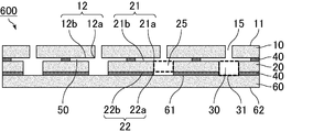
- the sound absorbing member of the present invention may be configured as shown in FIG. That is, in the sound absorbing member 600 which is an example of the sound absorbing member of the present invention, the first layer 10, the second layer 20, and the third layer 60 are sequentially laminated.
- the first layer 10 has a first major surface 11 and a second major surface 12 opposite to the first major surface 11.
- the first layer 10 has a first through hole 15 which penetrates the second major surface 12 from the first major surface 11 to form an introduction passage.
- the second major surface 12 is composed of a second major surface opening 12 a which is an end portion of the first through hole 15, and the other second major surface flat portion 12 b.
- the second layer 20 has a third major surface 21 facing the second major surface 12 and a fourth major surface 22 opposite to the third major surface 21.
- the second layer 20 has a second through hole 25 that penetrates the third major surface 21 to the fourth major surface 22.
- the third major surface 21 is composed of a third major surface opening 21 a which is an end of the second through hole 25 and the other third major surface flat portion 21 b.
- the fourth major surface 22 is composed of a fourth major surface opening 22a which is the other end of the second through hole 25 and the other fourth major surface flat 22b.
- the third layer 60 has a fifth major surface 61 facing the fourth major surface 22 and a sixth major surface 62 opposite to the fifth major surface 61.
- the opening area of the second main surface opening 12a is smaller than the opening area of the third main surface opening 21a.
- a part of the first layer 10 and the second layer 20 are adhered by the adhesive layer 40.
- the second through hole 25 forms the side surface of the hollow portion 30, and the fifth main surface 61 is the bottom surface 31 of the hollow portion 30.
- the second layer 20 and the third layer 60 are stacked by adhering the entire fourth major surface flat portion 22 and the fifth major surface 61 with the adhesive layer 40.
- a first air layer 50 is formed between the second major surface flat portion 12 b and the third major surface flat portion 21 b.
- the first air layer 50 is connected to the hollow portion 30.
- the sound absorbing member of the present invention may be configured as shown in FIG. That is, the sound absorbing member 700 which is an example of the sound absorbing member of the present invention is formed by sequentially laminating the first layer 10, the second layer 20, and the third layer 60.
- the first layer 10 has a first major surface 11 and a second major surface 12 opposite to the first major surface 11.
- the first layer 10 has a first through hole 15 which penetrates the second major surface 12 from the first major surface 11 to form an introduction passage.
- the second major surface 12 is composed of a second major surface opening 12 a which is an end portion of the first through hole 15, and the other second major surface flat portion 12 b.
- the second layer 20 has a third major surface 21 facing the second major surface 12 and a fourth major surface 22 opposite to the third major surface 21.
- the second layer 20 has a second through hole 25 that penetrates the third major surface 21 to the fourth major surface 22.
- the third major surface 21 is composed of a third major surface opening 21 a which is an end of the second through hole 25 and the other third major surface flat portion 21 b.
- the fourth major surface 22 is composed of a fourth major surface opening 22a which is the other end of the second through hole 25 and the other fourth major surface flat 22b.
- the third layer 60 has a fifth major surface 61 facing the fourth major surface 22 and a sixth major surface 62 opposite to the fifth major surface 61.
- the opening area of the second main surface opening 12a is smaller than the opening area of the third main surface opening 21a.
- a part of the first layer 10 and the second layer 20 are bonded by the adhesive layer 40.
- the second through hole 25 forms the side surface of the hollow portion 30, and the fifth main surface 61 is the bottom surface 31 of the hollow portion 30.
- the second layer 20 and the third layer 60 are laminated by bonding a part of the fourth major surface flat portion 22 and the fifth major surface by the adhesive layer 40.
- a first air layer 50 is formed between the second major surface flat portion 12 b and the third major surface flat portion 21 b.
- the first air layer 50 is connected to the hollow portion 30.
- a second air layer 70 is formed between the fourth major surface flat portion 22 and the fifth major surface 61.
- the second air layer 70 is connected to the hollow portion 30.
- the sound absorbing member of the present invention may be configured as shown in FIG. That is, the sound absorbing member 800, which is an example of the sound absorbing member of the present invention, is formed by sequentially laminating the first layer 10, the second layer 20, and the third layer 60.
- the first layer 10 has a first major surface 11 and a second major surface 12 opposite to the first major surface 11.
- the first layer 10 has a first through hole 15 which penetrates the second major surface 12 from the first major surface 11 to form an introduction passage.
- the second major surface 12 is composed of a second major surface opening 12 a which is an end portion of the first through hole 15, and the other second major surface flat portion 12 b.
- the second layer 20 has a third major surface 21 facing the second major surface 12 and a fourth major surface 22 opposite to the third major surface 21.
- the second layer 20 has a second through hole 25 that penetrates the third major surface 21 to the fourth major surface 22.
- the third major surface 21 is composed of a third major surface opening 21 a which is an end of the second through hole 25 and the other third major surface flat portion 21 b.
- the fourth major surface 22 is composed of a fourth major surface opening 22a which is the other end of the second through hole 25 and the other fourth major surface flat 22b.
- the third layer 60 has a fifth major surface 61 facing the fourth major surface 22 and a sixth major surface 62 opposite to the fifth major surface 61.
- the opening area of the second main surface opening 12a is smaller than the opening area of the third main surface opening 21a.
- the second through hole 25 forms the side surface of the hollow portion 30, and the fifth main surface 61 is the bottom surface 31 of the hollow portion 30.
- the male portion 12 ⁇ is formed in the second main surface flat portion 12b
- the female portion 21 ⁇ is formed in the third main surface flat portion 21b.
- the layer 10 and the second layer 20 are connected. Further, the second major surface flat portion 12b and the third major surface flat portion 21b are not in contact with each other except the male portion 12 ⁇ and the female portion 21 ⁇ , and the second major surface flat portion 12b and the third major surface flat
- the first air layer 50 is formed between the portion 21b.
- a female portion 22 ⁇ is formed in the fourth main surface flat portion 22b, and a male portion 61 ⁇ is formed in the fifth main surface, and these are fitted together to form the second layer 20 , And the third layer 60 are connected. Further, the fourth major surface flat portion 22 b and the fifth major surface 61 are not in contact with each other except for the female portion 22 ⁇ and the male portion 61 ⁇ , and the fourth major surface flat portion 22 b and the fifth major surface 61 A second air layer 70 is formed between them. The second air layer 70 is connected to the hollow portion 30. By forming the second air layer 70, the sound absorption coefficient is improved by the spring mass effect.
- the sound absorbing member of the present invention may be configured as shown in FIG. That is, the sound absorbing member 900, which is an example of the sound absorbing member of the present invention, is formed by sequentially laminating the first layer 10, the second layer 20, and the third layer 60.
- the first layer 10 has a first major surface 11 and a second major surface 12 opposite to the first major surface 11.
- the first layer 10 has a first through hole 15 which penetrates the second major surface 12 from the first major surface 11 to form an introduction passage.
- the second major surface 12 is composed of a second major surface opening 12 a which is an end portion of the first through hole 15, and the other second major surface flat portion 12 b.
- the second layer 20 has a third major surface 21 facing the second major surface 12 and a fourth major surface 22 opposite to the third major surface 21.
- the second layer 20 has a second through hole 25 that penetrates the third major surface 21 to the fourth major surface 22.
- the third major surface 21 is composed of a third major surface opening 21 a which is an end of the second through hole 25 and the other third major surface flat portion 21 b.
- the fourth major surface 22 is composed of a fourth major surface opening 22a which is the other end of the second through hole 25 and the other fourth major surface flat 22b.
- the third layer 60 has a fifth major surface 61 facing the fourth major surface 22 and a sixth major surface 62 opposite to the fifth major surface 61.
- the opening area of the second main surface opening 12a is smaller than the opening area of the third main surface opening 21a.
- the second through hole 25 forms the side surface of the hollow portion 30, and the fifth main surface 61 is the bottom surface 31 of the hollow portion 30.
- the second main surface flat portion 12b and the third main surface flat portion 21b are bonded by an adhesive at the end. Further, the first layer 10 is curved to be convex upward, and the first air layer 50 is formed between the second major surface flat portion 12 b and the third major surface flat portion 21 b. . That is, the second major surface flat portion 12b is curved so as to be convex upward.
- the first air layer 50 is connected to the hollow portion 30.
- the fourth major surface flat portion 22b and the fifth major surface 61 are bonded by an adhesive at the end. Further, the third layer 60 is curved to be convex downward, and a second air layer 70 is formed between the fourth major surface flat portion 22 b and the fifth major surface 61. That is, the fifth major surface 61 is curved to be convex downward.
- the second air layer 70 is connected to the hollow portion 30. By forming the second air layer 70, the sound absorption coefficient is improved by the spring mass effect.
- the method for producing the sound absorbing member of the present invention is Producing an upper layer which is a plate material having a columnar first through hole serving as an introduction passage; Producing a second layer which is a plate material having a second through hole; Preparing a plate material to be the third layer; Laminating the first layer and the second layer such that a first air layer is formed between the second main surface flat portion of the first layer and the third main surface flat portion of the second layer; And laminating the second layer and the third layer such that the hollow portion is formed.
- a plate material of a predetermined thickness made of a material such as a resin that can be used as a plate material is prepared.
- the first layer can be produced by forming the first through hole with a means such as punching, drill or laser for a plate material having no through hole.
- a foamed resin comprising expandable resin particles (beads) as a plate material
- the plate is also provided with a protrusion for forming the first through hole in the mold to foam the expandable resin particles.
- a first layer provided with a first through hole can be manufactured.
- a plate material of a predetermined thickness made of a material such as a resin that can be used as a plate material is prepared.
- the second layer can be produced by forming the second through hole by means of punching, drilling, laser or the like for the plate material having no through hole.
- the diameter of the second through hole is made larger than that of the first through hole.
- the plate is also provided with a projection for forming the second through hole in the mold to foam the expandable resin particles.
- a second layer provided with a second through hole can be manufactured.
- the fitting portion (male portion or female portion) is formed on the third major surface flat portion of the second layer. May be Moreover, you may form a fitting part (male part or female part) in the 4th main surface flat part of a 2nd layer in the process of laminating
- Step of preparing plate material to be the third layer A plate made of a material such as resin that can be used as a plate and having a predetermined thickness without a through hole is prepared.
- a fitting part male part or female part
- Step of laminating the first layer and the second layer Next, in the case of bonding the first layer and the second layer with an adhesive, a sheet-like adhesive is prepared in accordance with the shape and position of the second through hole of the second layer. At this time, the sheet-like adhesive layer is processed so that the first air layer is formed between the second main surface flat portion of the first layer and the third main surface flat portion of the second layer. .
- the first layer and the second layer can be bonded by the adhesive layer by exerting the adhesive force of the adhesive by sandwiching the first layer and the second layer.
- the adhesive is applied according to the shape and position of the second through hole of the second layer, the first layer and the second layer are laminated, and the adhesive force of the adhesive is exhibited, thereby the first layer and the second layer Can be adhered by an adhesive layer.
- the conditions for exerting the adhesive strength of the adhesive conditions in accordance with the adhesive characteristics of the adhesive may be used.
- Step of laminating the second layer and the third layer a sheet-like adhesive is prepared in accordance with the shape and position of the second through hole of the second layer.
- a sheet-like adhesive is prepared in accordance with the shape and position of the second through hole of the second layer.
- the second layer and the third layer can be bonded by the adhesive layer by exerting the adhesive force of the adhesive by sandwiching the second layer and the third layer. Thereby, a hollow part can be formed.
- the parts for vehicles of the present invention are characterized by including the sound absorbing member of the present invention. Since the sound absorbing member of the present invention is excellent in sound absorbing performance, it is excellent as a component for a vehicle. As parts for vehicles provided with the sound absorption member of the present invention, a raising member, a partition member, a luggage box, etc. are mentioned.
- An automobile according to the present invention is characterized in that the introduction passage of the sound absorbing member according to the present invention is disposed in the direction of the road surface.
- the sound absorbing member of the present invention is used as a vehicle component.
- An example in which the sound absorbing member of the present invention is used as a component for a vehicle and an example of an automobile in which the sound absorbing member of the present invention is disposed will be described with reference to FIGS. 10 (a) and 10 (b).
- Fig.10 (a) is explanatory drawing which shows typically an example of the site
- FIG.10 (b) is partial expansion of the area
- the automobile 1 includes a luggage room 3 at the rear of the rear seat 2.
- a plate-like floor member 4 is laid, and under the floor member 4, an underfloor space 5 is present.
- the sound absorbing member 100 is disposed under the underfloor space 5 of the automobile 1 such that the introduction passage 15 faces the road surface.
- Example 1 Preparation of Plate Material (1-1) Preparation of Plate Material to be First Layer Primary foamed particles (made of polypropylene, average particle diameter 3.5 mm, foaming agent: carbon dioxide) prepared by prefoaming expandable resin particles are made of gold. It is made of foamed resin by filling it in a mold, foaming it with heating steam (143 ° C, 10 seconds), removing it from the mold, and drying it at 80 ° C for 12 hours. A plate material having a size of 10 mm and serving as a first layer in which a fitting portion which is a male portion was formed at an edge portion of one main surface was produced. At this time, the expansion ratio of the foamed resin was 30 times.
- Primary foamed particles made of polypropylene, average particle diameter 3.5 mm, foaming agent: carbon dioxide
- prefoaming expandable resin particles are made of gold. It is made of foamed resin by filling it in a mold, foaming it with heating steam (143 ° C, 10 seconds), removing
- first through holes having a diameter of 3 mm are formed in the plate material to be the first layer manufactured in the above (1-1) so as to form a staggered arrangement of the hole pitch 10 mm.
- the first layer was prepared.
- a through hole (second through hole) is formed in a circular shape with a diameter of 10 mm in the plate material to be the second layer produced in the above (1-2) so as to form a staggered arrangement of hole pitch 10 mm, and a second layer is produced did.
- Example 2 (1) Preparation of Plate Material Primary foam particles (made of polypropylene, average particle diameter: 3.5 mm, foaming agent: carbon dioxide) prepared by prefoaming foamable resin particles are filled in a mold and foam molding is performed by heating steam (143) C. for 10 seconds, removed from the mold, and dried at 80.degree. C. for 12 hours to produce three plate members of 800 mm long x 800 mm wide x 10 mm thick made of a foamed resin. At this time, the expansion ratio of the foamed resin was 30 times.
- foaming agent carbon dioxide
- first through holes having a diameter of 3 mm are formed in one of the plate materials manufactured in the above (1) so as to form a staggered arrangement of the hole pitch 10 mm.
- the first layer was made.
- a through hole (second through hole) having a diameter of 10 mm is formed in another one of the plate materials manufactured in the above (1) so as to form a staggered arrangement of the hole pitch 10 mm, and the second layer is formed.
- the remaining one plate material produced in the above (1) was not processed but was used as the third layer.
- the first air layer was formed between the second main surface flat portion of the first layer and the third main surface flat portion of the second layer to which the adhesive is not applied.
- an adhesive Konishi HONDA G CO., LTD.
- an adhesive Konishi HONDA G CO., LTD.
- a second air layer was formed between the flat surface of the fourth main surface of the second layer to which the adhesive was not applied and the fifth main surface of the third layer.
- a sound absorbing member according to Example 2 having the structure shown in FIG. 7 was manufactured.
- the distance between the second main surface flat portion and the third main surface flat portion is 100 ⁇ m
- the distance between the fourth main surface flat portion and the fifth main surface is 100 ⁇ m. Met.
- FIG. 11 is an explanatory view schematically showing a reverberation chamber method sound absorption coefficient with respect to the sound absorption member.
- the sound absorbing member 100 according to each example and each comparative example is placed on the floor surface 81 of the reverberation chamber 80 with the opening of the introduction passage as the upper surface, In the reverberation chamber 80, the noise signal generator 82 radiates electrical noise through the speaker 83.
- the sound emission is then stopped, the sound is measured by the microphone 84 and the attenuation process is analyzed by the signal analyzer 85.
- the reverberation time which is the time for the sound to attenuate 60 dB from the analyzed attenuation curve before the test body is placed, T1 [sec. After the test body is placed on the floor surface, a reverberation time, which is a time when the sound attenuates by 60 dB from the measured attenuation curve, is T2 [sec. Ask for The measurement is performed at 300-5000 Hz.
- FIG. 12 is a graph showing the results of a reverberation chamber method sound absorption coefficient test of the sound absorbing member according to the first embodiment of the present invention.
- FIG. 13 is a graph showing the results of a reverberation chamber method sound absorption coefficient test of a sound absorbing member according to a second embodiment of the present invention.
- FIG. 14 is a graph showing the results of a reverberation chamber method sound absorption coefficient test of a sound absorbing member according to Comparative Example 1 of the present invention.
- the sound absorbing performance was high, and particularly, the peak of the sound absorption coefficient was high.
Landscapes
- Physics & Mathematics (AREA)
- Engineering & Computer Science (AREA)
- Acoustics & Sound (AREA)
- Multimedia (AREA)
- Mechanical Engineering (AREA)
- Vehicle Interior And Exterior Ornaments, Soundproofing, And Insulation (AREA)
- Soundproofing, Sound Blocking, And Sound Damping (AREA)
Abstract
L'invention concerne un élément absorbant acoustique qui possède une structure de résonance de Helmholtz qui est constituée d'une partie vide connectée à un trajet d'introduction et à une partie externe via ledit trajet d'introduction. L'élément absorbant acoustique de l'invention est caractéristique en ce qu'il contient une première couche et une seconde couche stratifiée sur ladite première couche. Ladite première couche possède une première face principale, et une seconde face principale côté opposé à ladite première face principale. Ladite seconde couche possède une troisième face principale en opposition à ladite seconde face principale, et une quatrième face principale côté opposé à ladite troisième face principale. Ladite première couche possède des premiers trous débouchant la transperçant de ladite première face principale à ladite seconde face principale, et formant ledit trajet d'introduction. Ladite seconde face principale est constituée de secondes parties ouverture de face principale consistant en la partie extrémité desdits premiers trous débouchant, et de secondes parties planes de face principale distinctes de ces dernières. Ladite troisième face principale est constituée de troisièmes parties ouverture de face principale consistant en la partie extrémité de ladite partie vide, et de troisièmes parties planes de face principale distinctes de ces dernières. La surface d'ouverture desdites secondes parties ouverture de face principale, est inférieure à la surface d'ouverture desdites troisièmes parties ouverture de face principale. Une première couche d'air est formée sur au moins une partie entre lesdites troisièmes parties ouverture de face principale.
Priority Applications (5)
| Application Number | Priority Date | Filing Date | Title |
|---|---|---|---|
| PCT/JP2017/027550 WO2019021483A1 (fr) | 2017-07-28 | 2017-07-28 | Élément absorbant acoustique, composant pour véhicule, et automobile |
| CN201780092624.2A CN110832576B (zh) | 2017-07-28 | 2017-07-28 | 吸音部件、车辆用构件和汽车 |
| EP17919029.3A EP3660834B1 (fr) | 2017-07-28 | 2017-07-28 | Élément absorbant acoustique, composant pour véhicule, et automobile |
| JP2019532344A JP7012085B2 (ja) | 2017-07-28 | 2017-07-28 | 吸音部材、車両用部品及び自動車 |
| US16/736,812 US11505137B2 (en) | 2017-07-28 | 2020-01-08 | Sound absorption member, vehicle component, and automobile |
Applications Claiming Priority (1)
| Application Number | Priority Date | Filing Date | Title |
|---|---|---|---|
| PCT/JP2017/027550 WO2019021483A1 (fr) | 2017-07-28 | 2017-07-28 | Élément absorbant acoustique, composant pour véhicule, et automobile |
Related Child Applications (1)
| Application Number | Title | Priority Date | Filing Date |
|---|---|---|---|
| US16/736,812 Continuation US11505137B2 (en) | 2017-07-28 | 2020-01-08 | Sound absorption member, vehicle component, and automobile |
Publications (1)
| Publication Number | Publication Date |
|---|---|
| WO2019021483A1 true WO2019021483A1 (fr) | 2019-01-31 |
Family
ID=65041059
Family Applications (1)
| Application Number | Title | Priority Date | Filing Date |
|---|---|---|---|
| PCT/JP2017/027550 WO2019021483A1 (fr) | 2017-07-28 | 2017-07-28 | Élément absorbant acoustique, composant pour véhicule, et automobile |
Country Status (5)
| Country | Link |
|---|---|
| US (1) | US11505137B2 (fr) |
| EP (1) | EP3660834B1 (fr) |
| JP (1) | JP7012085B2 (fr) |
| CN (1) | CN110832576B (fr) |
| WO (1) | WO2019021483A1 (fr) |
Cited By (3)
| Publication number | Priority date | Publication date | Assignee | Title |
|---|---|---|---|---|
| US10978038B2 (en) * | 2018-07-02 | 2021-04-13 | Toyota Motor Engineering & Manufacturing North America, Inc. | Invisible sound barrier |
| US11043199B2 (en) * | 2018-04-25 | 2021-06-22 | Toyota Motor Engineering & Manufacturing North America, Inc. | Sparse acoustic absorber |
| US11081095B2 (en) * | 2015-12-02 | 2021-08-03 | Université de Franche-Comté | Absorbent acoustic metamaterial |
Families Citing this family (2)
| Publication number | Priority date | Publication date | Assignee | Title |
|---|---|---|---|---|
| US11322126B2 (en) * | 2018-12-20 | 2022-05-03 | Toyota Motor Engineering & Manufacturing North America, Inc. | Broadband sparse acoustic absorber |
| WO2024013662A1 (fr) * | 2022-07-12 | 2024-01-18 | Elica S.P.A. | Dispositif d'absorption acoustique |
Citations (4)
| Publication number | Priority date | Publication date | Assignee | Title |
|---|---|---|---|---|
| JPH08260589A (ja) | 1995-03-27 | 1996-10-08 | Tokai Rubber Ind Ltd | 吸音部材 |
| JPH1039875A (ja) * | 1996-07-19 | 1998-02-13 | Mitsubishi Heavy Ind Ltd | 遮音材構造および空気調和機の防音構造 |
| JP2001249666A (ja) | 2000-03-07 | 2001-09-14 | Nissan Motor Co Ltd | 吸・遮音構造体及びその製造方法 |
| JP2012255967A (ja) * | 2011-06-10 | 2012-12-27 | Aisin Chemical Co Ltd | 熱硬化防音塗料組成物 |
Family Cites Families (13)
| Publication number | Priority date | Publication date | Assignee | Title |
|---|---|---|---|---|
| JPS57140511U (fr) * | 1981-02-28 | 1982-09-03 | ||
| JP3521577B2 (ja) * | 1995-11-09 | 2004-04-19 | 豊田合成株式会社 | 吸音材 |
| IT1293727B1 (it) * | 1997-07-18 | 1999-03-10 | Claudio Barabaschi | Pannello fonoassorbente ad assorbimento acustico per risonanza e procedimento di regolazione della frequenza di risonanza dello stesso |
| DE59810343D1 (de) * | 1998-07-10 | 2004-01-15 | Alstom Switzerland Ltd | Brennkammer für eine Gasturbine mit schalldämpfender Wandstruktur |
| JP2003140659A (ja) * | 2001-11-02 | 2003-05-16 | Nippon Tokushu Toryo Co Ltd | 吸音発泡プラスチック及びその製法 |
| JP2006199276A (ja) * | 2004-12-24 | 2006-08-03 | Kobe Steel Ltd | 吸音構造 |
| NO322685B1 (no) * | 2005-03-23 | 2006-11-27 | Deamp As | Plateelement |
| FR2899536B1 (fr) * | 2006-04-05 | 2009-02-20 | Peugeot Citroen Automobiles Sa | Dispositif d'absorption du bruit genere par un moteur de vehicule automobile |
| CA2805333C (fr) * | 2010-07-15 | 2016-02-09 | Aisin Kako Kabushiki Kaisha | Structure caracteristique d'absorption du son |
| CN102842303B (zh) * | 2011-06-23 | 2015-01-21 | 中国电力科学研究院 | 一种微孔纤维复合吸声板 |
| JP6077435B2 (ja) * | 2013-11-26 | 2017-02-08 | 理研軽金属工業株式会社 | 吸音構造体 |
| JP6566849B2 (ja) * | 2015-11-26 | 2019-08-28 | 日本プラスト株式会社 | 吸音構造体 |
| CN109263157B (zh) * | 2018-08-30 | 2021-01-26 | 无锡吉兴汽车部件有限公司 | 一种声功能部件及其应用 |
-
2017
- 2017-07-28 WO PCT/JP2017/027550 patent/WO2019021483A1/fr active Application Filing
- 2017-07-28 CN CN201780092624.2A patent/CN110832576B/zh active Active
- 2017-07-28 EP EP17919029.3A patent/EP3660834B1/fr active Active
- 2017-07-28 JP JP2019532344A patent/JP7012085B2/ja active Active
-
2020
- 2020-01-08 US US16/736,812 patent/US11505137B2/en active Active
Patent Citations (4)
| Publication number | Priority date | Publication date | Assignee | Title |
|---|---|---|---|---|
| JPH08260589A (ja) | 1995-03-27 | 1996-10-08 | Tokai Rubber Ind Ltd | 吸音部材 |
| JPH1039875A (ja) * | 1996-07-19 | 1998-02-13 | Mitsubishi Heavy Ind Ltd | 遮音材構造および空気調和機の防音構造 |
| JP2001249666A (ja) | 2000-03-07 | 2001-09-14 | Nissan Motor Co Ltd | 吸・遮音構造体及びその製造方法 |
| JP2012255967A (ja) * | 2011-06-10 | 2012-12-27 | Aisin Chemical Co Ltd | 熱硬化防音塗料組成物 |
Non-Patent Citations (1)
| Title |
|---|
| See also references of EP3660834A4 |
Cited By (3)
| Publication number | Priority date | Publication date | Assignee | Title |
|---|---|---|---|---|
| US11081095B2 (en) * | 2015-12-02 | 2021-08-03 | Université de Franche-Comté | Absorbent acoustic metamaterial |
| US11043199B2 (en) * | 2018-04-25 | 2021-06-22 | Toyota Motor Engineering & Manufacturing North America, Inc. | Sparse acoustic absorber |
| US10978038B2 (en) * | 2018-07-02 | 2021-04-13 | Toyota Motor Engineering & Manufacturing North America, Inc. | Invisible sound barrier |
Also Published As
| Publication number | Publication date |
|---|---|
| US11505137B2 (en) | 2022-11-22 |
| EP3660834A1 (fr) | 2020-06-03 |
| JPWO2019021483A1 (ja) | 2020-05-28 |
| EP3660834B1 (fr) | 2023-11-29 |
| US20200139902A1 (en) | 2020-05-07 |
| CN110832576A (zh) | 2020-02-21 |
| JP7012085B2 (ja) | 2022-01-27 |
| CN110832576B (zh) | 2023-05-26 |
| EP3660834A4 (fr) | 2021-03-10 |
Similar Documents
| Publication | Publication Date | Title |
|---|---|---|
| US11505137B2 (en) | Sound absorption member, vehicle component, and automobile | |
| JP5890833B2 (ja) | 広帯域吸音体 | |
| US7789197B2 (en) | Soundproofing assembly, use for soundproofing enclosed spaces, and method for making same | |
| US8695758B2 (en) | Soundproof sheet for vehicles, manufacturing method thereof, and dash silencer for vehicles using soundproof sheet | |
| KR101317818B1 (ko) | 흡음성능이 개선된 자동차용 대쉬 인너 인슐레이터 | |
| US11881198B2 (en) | Noise insulation material for automobile | |
| CN105034508B (zh) | 车辆用隔板垫 | |
| KR101874305B1 (ko) | 차량용 플로워카페트 및 그의 제조방법 | |
| WO2019008774A1 (fr) | Matériau absorbant le son, composant pour véhicule, et automobile | |
| JPWO2019186970A1 (ja) | 自動車用部品 | |
| WO2019021478A1 (fr) | Structure insonore, composant pour véhicule, et automobile | |
| WO2019021477A1 (fr) | Élément absorbant acoustique, composant pour véhicule, et automobile | |
| JPWO2019026294A1 (ja) | 吸音部材、車両用部品及び自動車 | |
| WO2019021480A1 (fr) | Élément absorbant acoustique ainsi que procédé de fabrication de celui-ci, composant pour véhicule, et automobile | |
| JP2018158691A (ja) | 車両用吸音材、車両用部品、自動車及び自動車用仕切り部材 | |
| KR101325523B1 (ko) | 흡음성능이 개선된 자동차용 트림 | |
| WO2019008775A1 (fr) | Corps structural insonorisé, composant pour véhicule, et automobile | |
| KR102516518B1 (ko) | 자동차용 대쉬 인슐레이터 및 이의 제조방법 | |
| JP2020008684A (ja) | 防音構造体 | |
| JP2008155775A (ja) | 車両用吸音材、及び車両用吸音材の製造方法 | |
| WO2020065716A1 (fr) | Matériau isolant acoustique pour véhicule | |
| JP2023154823A (ja) | 吸音材の製造方法、吸音材、及び車両部材 |
Legal Events
| Date | Code | Title | Description |
|---|---|---|---|
| 121 | Ep: the epo has been informed by wipo that ep was designated in this application |
Ref document number: 17919029 Country of ref document: EP Kind code of ref document: A1 |
|
| ENP | Entry into the national phase |
Ref document number: 2019532344 Country of ref document: JP Kind code of ref document: A |
|
| NENP | Non-entry into the national phase |
Ref country code: DE |
|
| WWE | Wipo information: entry into national phase |
Ref document number: 2017919029 Country of ref document: EP |