WO2019013206A1 - エンコーダ及び駆動装置 - Google Patents
エンコーダ及び駆動装置 Download PDFInfo
- Publication number
- WO2019013206A1 WO2019013206A1 PCT/JP2018/026034 JP2018026034W WO2019013206A1 WO 2019013206 A1 WO2019013206 A1 WO 2019013206A1 JP 2018026034 W JP2018026034 W JP 2018026034W WO 2019013206 A1 WO2019013206 A1 WO 2019013206A1
- Authority
- WO
- WIPO (PCT)
- Prior art keywords
- case
- temperature
- encoder
- pressure
- unit
- Prior art date
- Legal status (The legal status is an assumption and is not a legal conclusion. Google has not performed a legal analysis and makes no representation as to the accuracy of the status listed.)
- Ceased
Links
Images



Classifications
-
- G—PHYSICS
- G01—MEASURING; TESTING
- G01D—MEASURING NOT SPECIALLY ADAPTED FOR A SPECIFIC VARIABLE; ARRANGEMENTS FOR MEASURING TWO OR MORE VARIABLES NOT COVERED IN A SINGLE OTHER SUBCLASS; TARIFF METERING APPARATUS; MEASURING OR TESTING NOT OTHERWISE PROVIDED FOR
- G01D5/00—Mechanical means for transferring the output of a sensing member; Means for converting the output of a sensing member to another variable where the form or nature of the sensing member does not constrain the means for converting; Transducers not specially adapted for a specific variable
- G01D5/12—Mechanical means for transferring the output of a sensing member; Means for converting the output of a sensing member to another variable where the form or nature of the sensing member does not constrain the means for converting; Transducers not specially adapted for a specific variable using electric or magnetic means
- G01D5/244—Mechanical means for transferring the output of a sensing member; Means for converting the output of a sensing member to another variable where the form or nature of the sensing member does not constrain the means for converting; Transducers not specially adapted for a specific variable using electric or magnetic means influencing characteristics of pulses or pulse trains; generating pulses or pulse trains
- G01D5/24428—Error prevention
- G01D5/24433—Error prevention by mechanical means
- G01D5/24438—Special design of the sensing element or scale
-
- G—PHYSICS
- G01—MEASURING; TESTING
- G01D—MEASURING NOT SPECIALLY ADAPTED FOR A SPECIFIC VARIABLE; ARRANGEMENTS FOR MEASURING TWO OR MORE VARIABLES NOT COVERED IN A SINGLE OTHER SUBCLASS; TARIFF METERING APPARATUS; MEASURING OR TESTING NOT OTHERWISE PROVIDED FOR
- G01D5/00—Mechanical means for transferring the output of a sensing member; Means for converting the output of a sensing member to another variable where the form or nature of the sensing member does not constrain the means for converting; Transducers not specially adapted for a specific variable
- G01D5/12—Mechanical means for transferring the output of a sensing member; Means for converting the output of a sensing member to another variable where the form or nature of the sensing member does not constrain the means for converting; Transducers not specially adapted for a specific variable using electric or magnetic means
- G01D5/244—Mechanical means for transferring the output of a sensing member; Means for converting the output of a sensing member to another variable where the form or nature of the sensing member does not constrain the means for converting; Transducers not specially adapted for a specific variable using electric or magnetic means influencing characteristics of pulses or pulse trains; generating pulses or pulse trains
- G01D5/24428—Error prevention
-
- G—PHYSICS
- G01—MEASURING; TESTING
- G01D—MEASURING NOT SPECIALLY ADAPTED FOR A SPECIFIC VARIABLE; ARRANGEMENTS FOR MEASURING TWO OR MORE VARIABLES NOT COVERED IN A SINGLE OTHER SUBCLASS; TARIFF METERING APPARATUS; MEASURING OR TESTING NOT OTHERWISE PROVIDED FOR
- G01D5/00—Mechanical means for transferring the output of a sensing member; Means for converting the output of a sensing member to another variable where the form or nature of the sensing member does not constrain the means for converting; Transducers not specially adapted for a specific variable
- G01D5/12—Mechanical means for transferring the output of a sensing member; Means for converting the output of a sensing member to another variable where the form or nature of the sensing member does not constrain the means for converting; Transducers not specially adapted for a specific variable using electric or magnetic means
- G01D5/244—Mechanical means for transferring the output of a sensing member; Means for converting the output of a sensing member to another variable where the form or nature of the sensing member does not constrain the means for converting; Transducers not specially adapted for a specific variable using electric or magnetic means influencing characteristics of pulses or pulse trains; generating pulses or pulse trains
- G01D5/24428—Error prevention
- G01D5/24433—Error prevention by mechanical means
- G01D5/24442—Error prevention by mechanical means by mounting means
Definitions
- the present invention relates to an encoder and a drive device provided with the encoder.
- An encoder for example, a rotary encoder
- the motor is generally covered with resin to dissipate heat from the coil.
- the resin absorbs (moisture absorbs) moisture in the air when the motor is stopped, and releases moisture in the resin during operation. Therefore, during operation of the motor, the temperature of the coil rises rapidly, the resin of the motor also becomes high temperature, the moisture contained in the resin is released into the air, and the released water vapor also flows to the encoder side .
- an encoder for detecting rotation information of a first rotation shaft, the first detector for detecting a pattern provided on the first rotation shaft, and the first rotation shaft And a second accommodation housing at least a part of a shaft portion different from a portion provided with the pattern of the first housing case housing the first detector and the pattern provided in the second housing
- An encoder is provided that includes a case and an adjustment mechanism that makes at least one of air pressure and temperature in the first storage case higher than at least one of air pressure and temperature in the second storage case.
- a drive device comprising: the encoder of the first aspect; a motor unit for driving the first rotation shaft; and a control unit for controlling the motor unit using a detection result of the encoder Is provided.
- a first encoder for detecting rotation information of the first rotation shaft, a first storage case for storing the first encoder, a motor unit for driving the first rotation shaft, and the motor
- a second housing case for housing the first housing case and at least one of the pressure and temperature in the first housing case and the first housing case from the start of operation of the motor section to the saturation of the temperature of the motor section; [2] At least one of the air pressure and the temperature in the storage case is equal to each other, or at least one of the air pressure and the temperature in the first storage case is higher than at least one of the air pressure and the temperature in the second storage case And an adjusting mechanism for adjusting.
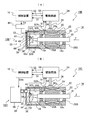
- (A) is sectional drawing which shows the drive device based on the 1st Embodiment of this invention
- (B) is sectional drawing which shows the drive device of a 1st modification.
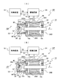
- (A) is sectional drawing which shows the drive device of a 2nd modification
- (B) is sectional drawing which shows the drive device concerning 2nd Embodiment.
- (A) is sectional drawing which shows the drive device of the modification of 2nd Embodiment
- (B) is sectional drawing which shows the drive device concerning 3rd Embodiment.
- (A) is sectional drawing which shows the drive device based on 4th Embodiment
- (B) is sectional drawing which shows the drive device of the modification.
- (A) is a cross-sectional view showing a drive apparatus according to a fifth embodiment
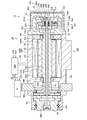
- (B) is a cross-sectional view showing a drive apparatus according to a sixth embodiment. It is sectional drawing which shows the drive device which concerns on 7th Embodiment. It is sectional drawing which shows the drive device which concerns on 8th Embodiment.
- FIG. 1A shows a schematic configuration of a drive device 10 according to the present embodiment.
- the drive device 10 includes an encoder unit 12, a motor unit 14, and a control unit 16 that controls the operation of the motor unit 14 based on the detection result of the encoder unit 12.
- the motor unit 14 has a box-like motor case 30 in which two openings facing each other are formed, and a pair of rotational bearings 28A provided on side portions (inner side surfaces) of the two openings formed in the motor case 30.
- At least a part of the magnet 20 and the coil 22 is covered with a resin (not shown) such as a synthetic resin, and while the motor unit 14 is stopped, the resin absorbs moisture in the surrounding air, and the motor unit 14 operates In the middle (during which current is supplied to the coil 22), the resin releases moisture into the surrounding air.
- the Z axis is taken parallel to the central axis of the rotating shaft 18 and described.
- the rotation axis 18 is rotatable about an axis parallel to the Z axis.
- the motor unit 14 is a three-phase AC motor, a DC motor or the like can also be used as the motor unit 14.
- a part of the shaft portion 18 c of the rotation shaft 18, the magnet 20, and the coil 22 are accommodated in the motor case 30.
- one end 18a in the + Z direction thinner than the shaft 18c of the rotary shaft 18 and the other end 18b in the -Z direction with the same outer diameter as the shaft 18c are side surfaces of the motor case 30 in the + Z and -Z directions, respectively. It protrudes outside.
- the encoder unit 12 is disposed on one end side of the rotation shaft 18.
- the encoder unit 12 is attached to the tip of one end 18a of the rotary shaft 18, and a disc on which a reflective pattern PA (hereinafter also referred to as a rotary detection pattern) for detecting the position in the rotational direction is formed.
- a reflective pattern PA hereinafter also referred to as a rotary detection pattern
- the rotary plate 34 has a detection unit 33 including a processing circuit 44 for obtaining information (hereinafter referred to as encoder information) S1 of the position (angle and / or angular velocity) of the rotational direction of (and the rotational shaft 18).
- the encoder information S1 is supplied to the drive circuit 24 and the control device 16.
- the rotary plate 34 can also be called a rotary scale or disc.
- the detection pattern PA formed on the rotary plate 34 may be any pattern such as an absolute type or an incremental type. Further, although the rotary plate 34 is of a reflective type, a transmissive pattern may be formed on the rotary plate 34.
- the control device 16 generates rotation command information S2 including information such as the rotation angle of the rotation shaft 18 using the information of the target rotation angle and / or the target rotation speed of the rotation shaft 18 and the encoder information S1.
- the command information S2 is supplied to the drive circuit 24.
- the drive circuit 24 adjusts the current supplied to the coil 22 using the rotation command information S2 and the encoder information S1 to control the rotation angle and / or the rotation speed of the rotation shaft 18. Furthermore, the drive circuit 24 supplies the control device 16 with current information S3 including the value of the current supplied to the coil 22.
- a flat substrate 38 is supported on the end surface of the motor case 30 in the + Z direction via a plurality of support members 36, and the light source 40, the light receiving element 42, and the processing circuit 44 are attached to the substrate 38.
- the box-like encoder case 32 is airtight so as to cover (accommodate) one end 18a of the rotating shaft 18, the detection unit 33, the substrate 38, and the support member 36 on the end surface of the motor case 30 in the + Z direction. It is attached.
- a flexible sheet-like heater 46 is provided on substantially the entire inner surface of the encoder case 32.
- the heater 46 is configured by sandwiching a sheet-like heat generating element such as metal between two sheets of an insulator (for example, silicone rubber) having flexibility and heat resistance.
- the control device 16 supplies heating command information S4 indicating the amount of heating to the power supply unit 48, and the power supply unit 48 controls the current supplied to the heater 46 accordingly, whereby the temperature of the heater 46 is controlled.
- the encoder unit 12 includes the encoder case 32, the detection unit 33, the substrate 38, the heater 46, and the power supply unit 48.
- the encoder case 32 is adjacent to the motor case 30, and the space 30S in the motor case 30 and the space 32S in the encoder case 32 are slightly separated via the gap in the rotary bearing 28A. It is in communication.
- the space 32S is in slight communication with the outside air through a gap in the rotary bearing 28B.
- the motor case 30 and the encoder case 32 may be separated.
- the processing circuit 44 of the encoder unit 12 supplies the drive circuit 24 and the control device 16 with encoder information S1 such as the angle of the rotary plate 34 (and the rotation shaft 18) obtained at a predetermined cycle. Then, the control device 16 supplies the rotation command information S2 generated using the encoder information S1 and the like to the drive circuit 24 of the motor unit 14, and controls the current value supplied to the coil 22 by the drive circuit 24 accordingly. By this operation, the rotation angle or the like of the rotating shaft 18 is controlled to the target value.
- the drive circuit 24 supplies the control device 16 with current information S3 including the value of the current supplied to the coil 22 at a predetermined cycle.
- a function hereinafter, referred to as a first temperature function
- a function hereinafter, referred to as a second temperature function
- the first and second temperature functions are stored in a storage unit in the controller 16.
- the control device 16 uses the current information S3 supplied from the drive circuit 24 to obtain a value obtained by integrating the current flowing through the coil 22, and predicts the temperature T30 of the space 30S from this value and its temperature function. Then, the control device 16 causes the power supply unit 48 so that the temperature T32 of the space 32S predicted using the second temperature function from the integrated value of the current (heating amount) flowing through the heater 46 becomes higher than the temperature T30.
- the heating command information S4 is supplied to control the heating amount of the heater 46.
- the temperature of the space 32S in the encoder case 32 becomes higher than the temperature of the space 30S in the motor case 30, and the air pressure in the space 32S becomes higher than the air pressure in the space 30S due to thermal expansion.
- the gas (air) in the space 32S flows into the space 30S through the rotary bearing 28A, and the gas in the space 30S flows out to the outside (outside air) through the rotary bearing 28B. For this reason, even if water vapor is generated from the resin of the motor unit 14 during operation of the motor unit 14, the air containing the water vapor (air with high humidity) hardly flows into the encoder case 32, so There is no risk of condensation.
- the encoder unit 12 can always detect the rotation angle or the like of the rotary plate 34 (rotation shaft 18) with high accuracy. The rotation of the rotary shaft 18 can be controlled with high accuracy by the motor unit 14 using the result.
- the power supply unit 48 may supply command information to turn off the current supplied to the heater 46. In other words, after the power is turned on, the temperature of the motor 46 rises until the temperature of the motor 46 settles at a constant temperature or after the operation of the motor unit 14 starts, and the temperature of the motor 46 is saturated (steady) In the meantime, command information for supplying current to the heater 46 is supplied to the power supply unit 48.
- the encoder unit 12 that detects rotation information (encoder information S1) of the rotation shaft 18 according to the present embodiment is disposed on the one end 18a side of the rotation shaft 18 and detects the pattern PA provided on the rotation shaft 18 Detection unit 33 (hereinafter, also referred to as a first detector), an encoder case 32 (hereinafter, also referred to as a first accommodation case) accommodating the pattern PA and the detection unit 33, and one end 18a of the rotating shaft 18
- the temperature and pressure of the space in the motor case 30 are at least one of the temperature and pressure of the space in the motor case 30 (hereinafter, also referred to as a second accommodation case) accommodating the at least part of the shaft portion 18c.
- a heater 46 as an adjusting mechanism for raising the pressure higher than at least one of the above.
- the air in the encoder case 32 is heated by the heater 46, and the air pressure is made higher than the air pressure in the motor case 30, so that the high humidity gas in the motor case 30 is the encoder case 32. It does not flow inside. Further, since the temperature of the surface of the detection unit 33 in the encoder case 32 can be made higher than the dew point by the heating of the heater 46, dew condensation in the encoder case 32 can be prevented. For this reason, the encoder unit 12 can always detect the rotation information of the rotating shaft 18 with high accuracy. Further, the adjustment mechanism is configured to set at least one of the temperature in the space in the encoder case 32 and the air pressure in the space in the motor case 30 until the temperature of the motor unit 14 becomes saturated after the operation of the motor unit 14 is started. The temperature may be higher than at least one of the temperature and the pressure.
- FIG. 1 (B) to FIG. 7 to be referred to below the parts corresponding to FIG. 1 (A) are given the same or similar reference numerals, and the detailed description thereof will be omitted.
- the illustration of the pattern PA of FIG. 1 (A) is omitted in FIGS. 1 (B) to 6.
- a reflective or transmissive optical detector is used as the detection unit 33.
- a detector of a magnetic type or a capacitive type may be used as a detection unit.
- the detection part 33 has the rotating plate 34, you may use the one end part 18a etc. of the rotating shaft 18 as a rotating plate.
- a magnetizing pattern or a reflection pattern indicating the position in the rotational direction may be formed on the surface of the one end portion 18a, and the rotational information may be detected by a detection unit including a magnetic sensor or a light receiving element.
- the mounting position of the scale (the rotary plate 34) may be a position other than the one end 18a of the rotary shaft 18, for example, a position apart from the other end 18b or the one end 18a and the other end 18b.
- the heater 46 is provided on the inner surface of the encoder case 32, but the sheet-like heater 46 is attached to the outer surface of the encoder case 32, and the temperature of the air in the encoder case 32 is measured from the outer surface. May be raised.
- an infrared heater may be installed in the encoder case 32, and the temperature of air in the encoder case 32 may be raised by this infrared heater.
- the infrared heater may be installed outside the encoder case 32, and the temperature of the air in the encoder case 32 and the inside thereof may be raised from the outside.
- control device 16 may control the heating amount of the heater 46 so that the temperature of the space 32S and the temperature of the space 30S become substantially the same.
- substantially the same means that, for example, if the gas does not intrude into the encoder case 32 from the inside of the motor case 30, the temperatures do not have to completely match. According to this configuration, it is possible to suppress the gas in the space 30S from flowing into the space 32S via the bearing 28A.
- the temperature of the space in the motor case 30 is predicted from the current supplied to the coil 22 of the motor unit 14.
- the encoder unit of the drive device 10A of the first modification of FIG. As indicated by 12A, the temperature of the space in the motor case 30 may be directly measured by the temperature sensor 50.
- a temperature sensor 50 such as a thermistor, a thermocouple, or a platinum resistance temperature sensor is disposed in a through hole 30a provided on the side surface of the motor case 30, and the temperature measuring portion of the temperature sensor 50 is a motor It projects into the space 30S in the case 30. The periphery of the through hole 30a is sealed.
- the temperature information S5 including the temperature of air in the space 30S measured by the temperature sensor 50 is supplied to the drive circuit 24 and the control device 16, and the control device 16 uses the temperature information S5 to use the encoder case
- the heating command information S4 is output to the power supply unit 48 so that the temperature of the space 32S in 32 becomes higher than the temperature of the space 30S. Therefore, the temperature of the space 32S can be controlled more accurately than the temperature of the space 30S, and condensation in the encoder case 32 can be prevented more reliably.
- a temperature sensor (not shown) for detecting the temperature of the space 32S in the encoder case 32 may be further provided. By using the measurement result of this temperature sensor, the temperature of the space 32S can be controlled more accurately.
- the air pressure in the motor case 30 may be directly measured by the pressure gauge 52A.
- a pressure gauge 52A such as a semiconductor type or strain gauge type pressure sensor is installed to cover the through hole 30a provided on the side surface of the motor case 30.
- the pressure information S6 including the pressure of the space 30S measured by the pressure gauge 52A is supplied to the drive circuit 24 and the control device 16, and the control device 16 uses the pressure information S6 to use the pressure of the space 32S in the encoder case 32.
- the heating command information S4 is output to the power supply unit 48 so that the pressure of the space 30S becomes higher than the pressure of the space 30S. Therefore, the air pressure of the space 32S can be controlled more accurately than the air pressure of the space 30S, and the inflow of high humidity air from the space 30S to the space 32S can be prevented more reliably, and in the encoder case 32. Condensation can be prevented more reliably.
- a pressure gauge 52B for detecting the pressure in the space 32S may be provided to cover the through hole 32a provided on the side surface of the encoder case 32.
- the air pressure of the space 32S can be more reliably increased than the air pressure of the space 30S.
- the controller 16 may control the air pressure or temperature of the space 32S in the encoder case 32 to be higher than the outside air pressure or the outside air temperature, respectively.
- the pressure or the temperature of the space 32S may be controlled to be higher than the pressure or the temperature of the space 30S in the motor case 30, respectively.
- FIG. 2B showing a drive unit 10C including the encoder unit 12C of the present embodiment
- a pressure gauge 52A for measuring the pressure of the space 30S in the motor case 30 is provided on the side surface of the motor case 30.
- the atmospheric pressure information S6 is supplied to the drive circuit 24 and the controller 16.
- the encoder case 32 is not provided with a heater. Instead, a pressure device 56 is provided which can supply a gas (air, an inert gas such as nitrogen, etc.) to the space 32S in the encoder case 32 through the pipe 54 to increase the pressure of the space 32S.
- a gas air, an inert gas such as nitrogen, etc.
- the control device 16 supplies the pressure device 56 with pressurization command information S4A including information of the set value of the air pressure higher than the air pressure of the space 30S included in the air pressure information S6.
- the pressurizing device 56 supplies the gas to the space 32S such that the pressure in the space 32S becomes higher than the pressure in the space 30S.
- the pressure device 56 is provided as an adjustment mechanism that makes the air pressure of the space 32S higher than the air pressure of the space 30S. For this reason, the inflow of high humidity air from the space 30S to the space 32S can be prevented more reliably, and condensation in the encoder case 32 can be prevented more reliably.
- pressure gauge 52B which detects the air pressure of space 32S is further provided in the side of encoder case 32, and it measures by pressure gauge 52B.
- the pressure information S6A including the information of the pressure of the space 32S may be supplied to the drive circuit 24 and the control device 16.
- the control device 16 may control so that the pressure or temperature of the space 32S in the encoder case 32 becomes higher than the outside pressure or the outside temperature, respectively. .
- the pressure or the temperature of the space 32S may be controlled to be higher than the pressure or the temperature of the space 30S in the motor case 30, respectively.
- FIG. 3B showing a drive unit 10E including the encoder unit 12E of the present embodiment
- pressure gauges 52A and 52B for measuring the air pressure in the spaces 30S and 32S are provided on the side surfaces of the motor case 30 and the encoder case 32.
- the pressure information S6 and S6A of the pressure gauges 52A and 52B are supplied to the drive circuit 24 and the control device 16.
- a pressure reducing device 58 is provided which exhausts the air in the space 30S in the motor case 30 through the pipe 54A to reduce the air pressure in the space 30S.
- the control device 16 supplies the pressure reducing instruction information S4B to the pressure reducing device 58 such that the pressure of the space 32S included in the pressure information S6A becomes higher than the pressure of the space 30S included in the pressure information S6.
- the decompression device 58 exhausts the air of the space 30S such that the pressure of the space 32S becomes higher than the pressure of the space 30S.
- the pressure reducing device 58 is provided as an adjustment mechanism that makes the pressure of the space 32S higher than the pressure of the space 30S. For this reason, the inflow of high humidity air from the space 30S to the space 32S can be prevented more reliably, and condensation in the encoder case 32 can be prevented more reliably.
- the pressure gauge 52B can be omitted.
- the adjusting mechanisms of the first to third embodiments described above may be used in combination.
- the control device 16 controls the pressure of the space 32S to be substantially equal to the pressure of the space 30S.
- the supply amount or the exhaust amount of air by the pressure reducing device 58 may be controlled.
- Substantially the same means, for example, that the air pressures do not have to completely match if the gas does not intrude into the encoder case 32 from the inside of the motor case 30. According to these configurations, it is possible to suppress the gas in the space 30S from flowing into the space 32S via the bearing 28A.
- FIG. 4A showing the drive device 10F including the encoder unit 12F of the present embodiment, the cross-sectional shape of the motor case 30A is formed larger than the cross-sectional shape of the encoder case 32. Further, no heater is provided in the encoder case 32, and the pressurizing device and the pressure reducing device are not connected to the encoder case 32 and the motor case 30A.
- an exhaust hole 30Aa for letting the air of the space 30AS in the motor case 30A flow out is provided.
- the amount of air flowing from the space 30AS into the space 32S through the rotary bearing 28A as shown by the arrow A1 is smaller than the amount of air flowing out from the space 30AS through the exhaust hole 30Aa as shown by the arrow A2.
- the size of the exhaust hole 30Aa is set to increase the amount.
- the exhaust hole 30Aa is provided as an adjustment mechanism that makes the air pressure of the space 32S higher than the air pressure of the space 30AS. Therefore, the amount of high humidity air flowing into the space 32S from the space 30AS decreases, and the occurrence of condensation in the encoder case 32 can be suppressed with a simple configuration.
- the exhaust holes 30Aa may be provided at a plurality of locations of the motor case 30A.
- a heater may be provided in the encoder case 32, and a pressing device may be connected to the encoder case 32.
- a heater may be provided in the encoder case 32, and a pressure reducing device may be connected to the motor case 30A.
- a pressure device may be connected to the encoder case 32, and a pressure reducing device may be connected to the motor case 30A.
- FIG. 4B even if a plurality of (one may be) exhaust holes 32b and 32c for allowing air in the space 32S to flow out to the outside is provided on the side surface of the encoder case 32. Good.
- the total area of the sectional shapes of the exhaust holes 32b and 32c is set smaller than the area of the sectional shape of the exhaust hole 30Aa as an example, and the amount of gas flowing out from the exhaust holes 32b and 32c is the gas flowing out of the exhaust hole 30Aa Less than the amount of In this modification, high humidity air flowing from the space 30AS into the space 32AS through the rotary bearing 28A is exhausted to the outside from the exhaust holes 32b and 32c, so condensation in the encoder case 32 is prevented more reliably. it can.
- FIG. 5A showing the drive device 10G provided with the encoder unit 12G of the present embodiment
- no exhaust hole is provided in the motor case 30A.
- a cylindrical metal cooling member 60 is disposed so as to surround a region close to the rotary plate 34 of one end 18a of the rotary shaft 18, and the cooling member 60 is supported by the support member 36. ing.
- the heat capacity of the cooling member 60 is set larger than the heat capacity of the rotary plate 34.
- the other configuration is the same as that of the fourth embodiment.
- the cooling member 60 even if the temperature of the rotary plate 34 (scale) in the encoder case 32 rises by a predetermined temperature due to the influence of heat generation by energization of the coil 22 of the motor unit 14, the cooling member 60 The temperature does not rise as much as the predetermined temperature. Therefore, when high humidity air flows from the space 30AS in the motor case 30A into the space 32S in the encoder case 32, the air passes through the space between the cooling member 60 and one end 18a of the rotating shaft 18 In this case, condensation occurs on the surface of the cooling member 60 having a lower temperature, and condensation on the surface of the rotary plate 34 is suppressed. Therefore, the rotation information of the rotating shaft 18 can be detected with high accuracy by the encoder unit 12G. Also in this embodiment, the adjusting mechanisms of the first to fourth embodiments described above may be used in combination.
- FIG. 5 (B) showing the drive device 10H including the encoder unit 12H of the present embodiment
- the moistureproof agent 62 is provided on the substrate 38 inside the encoder case 32.
- the processing circuit 44A of the detection unit 33 obtains information S7 indicating the absorbed amount of humidity (moisture) of the moistureproof agent 62, for example, by measuring the resistance value of the moistureproof agent 62. It supplies the control device 16.
- the other configuration is the same as that of the first embodiment.
- the occurrence of dew condensation in the encoder case 32 can be prevented during the period in which the moistureproof agent 62 efficiently absorbs the humidity. Further, from the information S7 indicating the moisture absorption amount of the moistureproof agent 62, the control device 16 determines whether the moisture absorption action of the moistureproof agent 62 is lower than the allowable range. Then, when the moisture absorption action of the moistureproof agent 62 falls below the allowable range, the control device 16 supplies the heating command information S4 to the power supply unit 48 to heat the heater 46 in the encoder case 32, and the motor case The inflow of high humidity air from the space 30S in the space 30 to the space 32S in the encoder case 32 is suppressed. As a result, even if the moisture absorption effect of the moistureproof agent 62 is reduced, the occurrence of condensation within the encoder case 32 can be prevented.
- control device 16 may control the air pressure or temperature of the space 32S in the encoder case 32 to be higher than the outside air pressure or the outside air temperature, respectively.
- the pressure or the temperature of the space 32S may be controlled to be higher than the pressure or the temperature of the space 30S in the motor case 30, respectively.
- the adjusting mechanisms of the first to fourth embodiments described above may be used in combination.
- the moistureproof agent 62 of this embodiment may be used in combination with the first to fifth embodiments described above.
- the driving device 10I is a so-called double encoder type encoder unit 12I, a motor unit 14A and a motor unit 14A based on detection results of the encoder unit 12I.
- a controller 16 for controlling the operation.
- a fixing plate 30F is fixed so as to cover the end of the box-shaped case 30C in the + Z direction.
- a first rotary shaft 18A having a through hole 18Ac formed therein is supported rotatably via a pair of rotary bearings 28A and 28B.
- a rod-like second rotary shaft 18B elongated relative to the first rotary shaft 18 is disposed inside the first rotary shaft 18A.
- a first rotary plate 34A on which a reflective detection type rotary detection pattern is formed is attached to a support member 36A provided at the tip of one end 18Aa of the first rotary shaft 18A, and one end 18Ba of the second rotary shaft 18B
- a second rotary plate 34B on which a reflective and rotational detection pattern is formed is attached.
- the input shaft of the reduction gear 66 is connected to the other end 18Ab of the first rotation shaft 18A, and the output shaft of the reduction gear 66 is connected to the other end 18Bb of the second rotation shaft 18B.
- the reduction gear 66 reduces the number of rotations of the first rotation shaft 18A to about 1/300 and transmits it to the second rotation shaft 18B.
- a motor case 30B is configured of the case 30C, the fixing plate 30F, the flange portion 30D, and the support member 30E.
- the motor unit 14A includes the first and second rotary shafts 18A and 18B, the magnet 20 mounted on the outer surface of the central shaft portion 18Ac of the first rotary shaft 18A, and the case 30C so as to surround the magnet 20. And a drive circuit 24 A connected to the coil 22 via a plurality of signal lines 26.
- the rotation axes 18A and 18B are each rotatable around an axis parallel to the Z axis.
- the cylindrical support member 30G having a step is fixed to the end of the case 30C in the + Z direction, and the inner surface of the mounting member 70 fixed to the surface of the support member 30G in the + Z direction
- One end 18Ba of 18B is supported.
- the substrate 38A is supported on the inner surface of the support member 30G via the support member 36, and the substrate 38B is supported on the surface of the mounting member 70 in the + Z direction.
- the encoder unit 12I includes a first rotary plate 34A, a light source 40A for detecting encoder information S1A of the first rotary plate 34A, a first detection unit 33A including a light receiving element 42A, and a processing circuit 44A, and a second rotary plate 34B, a light source 40B for detecting encoder information S1B of the second rotary plate 34B, a light receiving element 42B, and a second detection unit 33B including a processing circuit 44B.
- the detectors 33A and 33B are attached to the substrates 38A and 38B.
- the encoder information S1A and S1B are supplied to the drive circuit 24A and the control device 16.
- Encoder case 32A is attached in an airtight state. Further, a flexible sheet-like heater 46A is provided on substantially the entire inner surface of the encoder case 32A. The temperature of the heater 46A is controlled by the control device 16 supplying heating command information indicating the amount of heating to the power supply unit (not shown) and controlling the current supplied to the heater 46A in accordance with the control. The configuration other than this is the same as that of the first embodiment.
- the encoder unit 12I supplies encoder information S1A, S1B of the rotary plates 34A, 34B (rotational shafts 18A, 18B) to the drive circuit 24A and the control device 16. Then, the control device 16 supplies the rotation command information S2 generated using the encoder information S1A, S1B, etc. to the drive circuit 24A of the motor unit 14A, and controls the current value supplied to the coil 22 by the drive circuit 24A accordingly. Do. By this operation, the rotation angle or the like of the second rotation shaft 18B is controlled to the target value.
- the drive circuit 24A supplies the control device 16 with current information S3 including the value of the current supplied to the coil 22.
- the control device 16 controls the heating amount of the heater 46A using the current information S3 so that the temperature of the space 32AS in the encoder case 32A becomes higher than the temperature of the space 30BS in the motor case 30B. Then, due to the thermal expansion of the air in the space 32AS, 30BS, the air pressure in the space 32AS becomes higher than the air pressure in the space 30BS.
- the adjustment mechanisms of the second to fifth embodiments described above may be used or used in combination as an adjustment mechanism for making the air pressure in the space 32AS higher than the air pressure in the space 30BS.
- the first rotary shaft 18A and the second rotary shaft 18A are set by setting the pressure in the space 32AS higher than the atmospheric pressure in which the drive device 10I is installed, with the pressure in the space 32AS higher than the pressure in the space 30BS. It is also possible to suppress the inflow of air through the gap with the rotating shaft 18B.
- the control device 16 may control so that the pressure or temperature of the space in the encoder case 32A becomes higher than the outside pressure or the outside temperature, respectively.
- the pressure or the temperature of the space in the encoder case 32A may be controlled to be higher than the pressure or the temperature of the space in the motor case 30B.
- a temperature sensor 50A for measuring the temperature of the space 30S in the motor case 30 is provided in the through hole 30a on the side of the motor case 30.
- a temperature sensor 50B for measuring the temperature of the space 32S in the encoder case 32 is provided in the through hole 32d on the side surface 32.
- Temperature information S5A, S5B including the temperature of the air in the spaces 30S, 32S measured by the temperature sensors 50A, 50B is supplied to the drive circuit 24 and the control device 16.
- the encoder case 32 is not provided with a heater, but a cooling element 49 for cooling the motor case 30 is provided on the outer surface of the motor case 30.
- a cooling element 49 for example, a Peltier element or a mechanism for circulating a cooled liquid through a pipe provided on the side surface of the motor case 30 can be used.
- the control device 16 supplies heat absorption command information S4C indicating heat absorption to the power supply unit 48A, and the electric power supply unit 48A controls the current supplied to the cooling element 49 accordingly, thereby providing the motor case 30 to which the cooling element 49 is mounted.
- the temperature of the inner space 30S is controlled.
- the other configuration is the same as that of the embodiment of FIG. 1 (B).
- the control device 16 uses the temperature information of the spaces 30S, 32S measured by the temperature sensors 50A, 50B, and as an example, the temperature of the space 32S in the encoder case 32 is the space 30S in the motor case 30.
- the temperature of motor case 30 is lowered using temperature sensors 50A, 50B and cooling element 49 (adjustment mechanism) so as to be higher than the temperature.
- the air pressure in the space 32S becomes higher than the air pressure in the space 30S, so that high humidity air from the space 30S can be prevented from flowing into the space 32S, and condensation in the encoder case 32 can be prevented.
- the controller 16 may control the heat absorption amount of the cooling element 49 so that the temperature of the space 32S and the temperature of the space 30S become substantially the same.
- substantially the same means that, for example, if the gas does not intrude into the encoder case 32 from the inside of the motor case 30, the temperatures do not have to completely match. According to this configuration, it is possible to suppress the gas in the space 30S from flowing into the space 32S via the bearing 28A.
- control device 16 may control so that the pressure or temperature of the space 32S in the encoder case 32 becomes higher than the outside pressure or the outside temperature, respectively.
- the pressure or the temperature of the space 32S may be controlled to be higher than the pressure or the temperature of the space 30S in the motor case 30, respectively.
- the pressure or temperature adjustment mechanism of the above-described first to seventh embodiments may be used in combination.
- the drive devices 10 to 10 J according to the above-described embodiments and their modifications can be used as drive mechanisms for various machine tools or robot devices.
- Coil 24 drive circuit 28A, 28B: rotational bearing 30, 30, 30A, 30B: motor case 32, 32A: encoder case 34, 34A, 34B: rotating plate 40, 40A, 40B: light source 42, 42A, 42B: light receiving element, 44: processing circuit, 46: heater, 49: cooling element, 50: temperature sensor, 52A, 52B: pressure gauge, 56: pressurizing device, 58: pressure reducing device, 60: cooling member, 66: deceleration Machine
Landscapes
- Physics & Mathematics (AREA)
- General Physics & Mathematics (AREA)
- Optical Transform (AREA)
- Transmission And Conversion Of Sensor Element Output (AREA)
Abstract
第1回転軸の回転情報を検出するエンコーダであって、前記第1回転軸に設けられたパターンを検出する第1検出器と、前記第1回転軸に設けられたパターン及び前記第1検出器を収容する第1収容ケースと、前記第1回転軸のうち、前記パターンが設けられた部分とは異なる軸部の少なくとも一部を収容する第2収容ケースと、前記第1収容ケース内の気圧と温度との少なくとも一方を前記第2収容ケース内の気圧と温度との少なくとも一方よりも高くする調整機構と、を備える。モータ側からエンコーダへの高湿度の空気の流入を防止又は抑制して、エンコーダ内での結露の発生を防止又は抑制できる。
Description
本発明は、エンコーダ及びエンコーダを備えた駆動装置に関する。
産業用ロボット又は工作機械等の駆動部に用いられるモータの回転角の制御を高精度に行うために、モータの回転軸にはエンコーダ(例えばロータリーエンコーダ)が取り付けられている。そして、モータの制御は、エンコーダの検出結果に基づいて行われている。モータは、一般にコイルからの熱を排熱するために、樹脂で覆われている。その樹脂は、モータの停止時に空気中の水分を吸収(吸湿)し、運転時に樹脂中の水分を放出する。そのため、モータの運転時には、コイルが急速に昇温し、モータの樹脂も高温になり、樹脂に含まれていた水分が空気中に放出され、放出された水蒸気がエンコーダ側にも流れることになる。このとき、エンコーダはまだ加熱されていないため、その水蒸気がエンコーダ内で結露する恐れがあった。このような結露を防止するために、エンコーダ内に吸湿剤を配置することが提案されている(例えば、引用文献1参照)。
最近では、エンコーダが取り付けられたモータはより様々な環境下で使用されるようになっており、さらにエンコーダの検出精度を常に高精度に維持することも求められている。このため、エンコーダ内での結露の防止、又は結露の抑制をより効果的に行うことが求められている。
本発明の第1の態様によれば、第1回転軸の回転情報を検出するエンコーダであって、その第1回転軸に設けられたパターンを検出する第1検出器と、その第1回転軸に設けられたパターン及びその第1検出器を収容する第1収容ケースと、その第1回転軸のうち、そのパターンが設けられた部分とは異なる軸部の少なくとも一部を収容する第2収容ケースと、その第1収容ケース内の気圧と温度との少なくとも一方をその第2収容ケース内の気圧と温度との少なくとも一方よりも高くする調整機構と、を備えるエンコーダが提供される。
第2の態様によれば、第1の態様のエンコーダと、その第1回転軸を駆動するモータ部と、そのエンコーダの検出結果を用いてそのモータ部を制御する制御部と、を備える駆動装置が提供される。
第3の態様によれば、第1回転軸の回転情報を検出する第1エンコーダと、その第1エンコーダを収容する第1収容ケースと、その第1回転軸を駆動するモータ部と、そのモータ部を収容する第2収容ケースと、そのモータ部の運転を開始してからそのモータ部の温度が飽和するまでの間、その第1収容ケース内の気圧と温度との少なくとも一方と、その第2収容ケース内の気圧と温度との少なくとも一方とを互いに等しく、もしくはその第1収容ケース内の気圧と温度との少なくとも一方をその第2収容ケース内の気圧と温度との少なくとも一方よりも高く調整する調整機構と、を備える駆動装置が提供される。
第3の態様によれば、第1回転軸の回転情報を検出する第1エンコーダと、その第1エンコーダを収容する第1収容ケースと、その第1回転軸を駆動するモータ部と、そのモータ部を収容する第2収容ケースと、そのモータ部の運転を開始してからそのモータ部の温度が飽和するまでの間、その第1収容ケース内の気圧と温度との少なくとも一方と、その第2収容ケース内の気圧と温度との少なくとも一方とを互いに等しく、もしくはその第1収容ケース内の気圧と温度との少なくとも一方をその第2収容ケース内の気圧と温度との少なくとも一方よりも高く調整する調整機構と、を備える駆動装置が提供される。
以下、第1の実施形態につき図1(A)を参照して説明する。
図1(A)は、本実施形態に係る駆動装置10の概略構成を示す。図1(A)において、駆動装置10は、エンコーダ部12と、モータ部14と、エンコーダ部12の検出結果に基づいてモータ部14の動作を制御する制御装置16とを備えている。モータ部14は、互いに対向する2つの開口が形成された箱状のモータケース30と、モータケース30に形成された2つの開口の側面部(内側面)に設けられた1対の回転軸受28A及び28Bと、この1対の回転軸受28A及び28Bを介して回転可能に支持された細長い棒状の回転軸18と、回転軸18の中央の軸部18cの外面に装着された複数のマグネット20と、マグネット20を囲むようにモータケース30の内面に配置された複数のコイル22と、コイル22に複数の信号ライン26を介して接続された駆動回路24とを有する。マグネット20及びコイル22の少なくとも一部は合成樹脂等の樹脂(不図示)によって覆われ、モータ部14の停止中には、その樹脂は周囲の空気中の水分を吸収し、モータ部14の運転中(コイル22に電流を供給する期間)には、その樹脂は水分を周囲の空気中に放出する。以下では、回転軸18の中心軸に平行にZ軸を取って説明する。回転軸18はZ軸に平行な軸の回りに回転可能である。
図1(A)は、本実施形態に係る駆動装置10の概略構成を示す。図1(A)において、駆動装置10は、エンコーダ部12と、モータ部14と、エンコーダ部12の検出結果に基づいてモータ部14の動作を制御する制御装置16とを備えている。モータ部14は、互いに対向する2つの開口が形成された箱状のモータケース30と、モータケース30に形成された2つの開口の側面部(内側面)に設けられた1対の回転軸受28A及び28Bと、この1対の回転軸受28A及び28Bを介して回転可能に支持された細長い棒状の回転軸18と、回転軸18の中央の軸部18cの外面に装着された複数のマグネット20と、マグネット20を囲むようにモータケース30の内面に配置された複数のコイル22と、コイル22に複数の信号ライン26を介して接続された駆動回路24とを有する。マグネット20及びコイル22の少なくとも一部は合成樹脂等の樹脂(不図示)によって覆われ、モータ部14の停止中には、その樹脂は周囲の空気中の水分を吸収し、モータ部14の運転中(コイル22に電流を供給する期間)には、その樹脂は水分を周囲の空気中に放出する。以下では、回転軸18の中心軸に平行にZ軸を取って説明する。回転軸18はZ軸に平行な軸の回りに回転可能である。
一例として、モータ部14は3相交流モータであるが、モータ部14としては直流モータ等も使用できる。本実施形態では、回転軸18の軸部18cの一部、マグネット20、及びコイル22はモータケース30内に収容されている。一方、回転軸18の軸部18cよりも細い+Z方向の一端部18a及び軸部18cと同じ外径の-Z方向の他端部18bはそれぞれモータケース30の+Z方向及び-Z方向の側面の外側に突き出ている。
また、エンコーダ部12は、回転軸18の一端部側に配置される。エンコーダ部12は、回転軸18の一端部18aの先端に取り付けられて、回転方向の位置を検出するための反射型のパターンPA(以下、回転型の検出パターンとも称する)が形成された円板状の回転板34と、回転板34のパターンPAに検出光を照射する光源40と、パターンPAからの反射光を受光する受光素子42と、受光素子42の検出信号を処理して回転板34(及び回転軸18)の回転方向の位置(角度及び/又は角速度)の情報(以下、エンコーダ情報という)S1を求める処理回路44とを含む検出部33を有する。エンコーダ情報S1は、駆動回路24及び制御装置16に供給される。回転板34は、回転型のスケール又はディスクとも呼ぶことができる。なお、回転板34に形成される検出パターンPAは、アブソリュート型又はインクリメンタル型等のどのようなパターンであってもよい。また、回転板34は反射型であるが、回転板34には透過型のパターンが形成されていてもよい。
制御装置16は、回転軸18の目標回転角及び/又は目標回転速度の情報と、エンコーダ情報S1とを用いて回転軸18の回転角等の情報を含む回転指令情報S2を生成し、その回転指令情報S2を駆動回路24に供給する。駆動回路24は、回転指令情報S2及びエンコーダ情報S1を用いて、コイル22に供給する電流を調整して回転軸18の回転角及び/又は回転速度を制御する。さらに、駆動回路24は、コイル22に供給する電流値を含む電流情報S3を制御装置16に供給する。
モータケース30の+Z方向の端面に複数の支持部材36を介して平板状の基板38が支持され、基板38に光源40、受光素子42、及び処理回路44が取り付けられている。また、モータケース30の+Z方向の端面に、回転軸18の一端部18a、検出部33、基板38、及び支持部材36を覆う(収容する)ように、箱状のエンコーダケース32が気密状態で取り付けられている。さらに、エンコーダケース32の内面のほぼ全面に、可撓性を持つシート状のヒータ46が設けられている。ヒータ46は、一例として、可撓性及び耐熱性を有する絶縁体(例えばシリコンゴムなど)の2枚のシートの間に金属等のシート状の発熱体を挟んで構成されている。制御装置16が加熱量を示す加熱指令情報S4を電源部48に供給し、それに応じて電源部48がヒータ46に供給する電流を制御することで、ヒータ46の温度が制御される。エンコーダケース32、検出部33、基板38,ヒータ46、及び電源部48を含んでエンコーダ部12が構成されている。本実施形態では、モータケース30に対してエンコーダケース32は隣接しており、モータケース30内の空間30Sと、エンコーダケース32内の空間32Sとは、回転軸受28A内の隙間を介してわずかに連通している。また、空間32Sは回転軸受28B内の隙間を介して外気とわずかに連通している。なお、モータケース30とエンコーダケース32とは離れていてもよい。
本実施形態の駆動装置10の動作の一例につき説明する。まず、エンコーダ部12の処理回路44は、所定の周期で求めた回転板34(及び回転軸18)の角度等のエンコーダ情報S1を駆動回路24及び制御装置16に供給する。そして、制御装置16が、エンコーダ情報S1等を用いて生成した回転指令情報S2をモータ部14の駆動回路24に供給し、それに応じて駆動回路24がコイル22に供給する電流値を制御する。この動作によって回転軸18の回転角等が目標値に制御される。
また、駆動回路24は、所定の周期で、コイル22に供給する電流値を含む電流情報S3を制御装置16に供給する。予め、モータ部14のコイル22に流れる電流を経過時間に応じて積算した値(積分値)と、モータケース30内の空間30Sの温度との関係を示す関数(以下、第1温度関数という)と、エンコーダケース32内のヒータ46に流す電流を積算した値と、エンコーダケース32内の空間32Sの温度との関係を示す関数(以下、第2温度関数という)とが求められており、その第1及び第2温度関数が制御装置16内の記憶部に記憶されている。制御装置16は、駆動回路24から供給される電流情報S3を用いて、コイル22に流れる電流を積算した値を求め、この値とその温度関数とから空間30Sの温度T30を予測する。そして、制御装置16は、ヒータ46に流れる電流(加熱量)の積算値からその第2温度関数を用いて予測される空間32Sの温度T32がその温度T30よりも大きくなるように、電源部48に加熱指令情報S4を供給して、ヒータ46の加熱量を制御する。
これによって、エンコーダケース32内の空間32Sの温度はモータケース30内の空間30Sの温度よりも高くなり、熱膨張によって、空間32S内の気圧は、空間30S内の気圧よりも高くなる。そして、空間32Sの気体(空気)は、回転軸受28Aを介して空間30Sに流入し、空間30Sの気体は回転軸受28Bを介して外部(外気)に流出する。このため、モータ部14の運転中にモータ部14の樹脂から水蒸気が発生しても、その水蒸気を含む空気(高湿度の空気)はエンコーダケース32内にほとんど流入しないため、エンコーダケース32内で結露が生じる恐れはなくなる。また、エンコーダケース32内に高湿度の空気がわずかに流入しても、ヒータ46によってエンコーダケース32内の空間30Sの温度が高くなり、エンコーダケース32内の検出部33の構成部材(回転板34、光源40、受光素子42)の表面の温度が露点よりも高くなるため、エンコーダケース32内で結露が生じる恐れはさらに小さくなる。したがって、モータ部14の運転を継続しても、エンコーダケース32内で結露が生じないため、エンコーダ部12によって常に高精度に回転板34(回転軸18)の回転角等を検出でき、この検出結果を用いてモータ部14によって回転軸18の回転を高精度に制御できる。
なお、制御装置16は、モータ部14の運転によって、エンコーダケース32内の検出部33の各構成部材の表面の温度が露点よりも高くなり、ヒータ46を加熱する必要がなくなったと判断できる場合には、電源部48にヒータ46に供給する電流をオフにする指令情報を供給してもよい。
言い換えると、電源を投入した後、モータ46の温度が一定の温度に落ち着くまでの間、またはモータ部14の運転開始後、モータ46の温度が上昇し、モータ46の温度が飽和状態(定常)になるまでの間は、電源部48にヒータ46に電流を供給する指令情報が供給される。
言い換えると、電源を投入した後、モータ46の温度が一定の温度に落ち着くまでの間、またはモータ部14の運転開始後、モータ46の温度が上昇し、モータ46の温度が飽和状態(定常)になるまでの間は、電源部48にヒータ46に電流を供給する指令情報が供給される。
上述のように本実施形態の回転軸18の回転情報(エンコーダ情報S1)を検出するエンコーダ部12は、回転軸18の一端部18a側に配置され、回転軸18に設けられたパターンPAを検出する検出部33(以下、第1検出器ともいう)と、パターンPA及び検出部33を収容するエンコーダケース32(以下、第1収容ケースともいう)と、回転軸18の一端部18aとは異なる軸部18cの少なくとも一部を収容するモータケース30(以下、第2収容ケースともいう)と、エンコーダケース32内の空間の温度と気圧との少なくとも一方をモータケース30内の空間の温度と気圧との少なくとも一方よりも高くする調整機構としてのヒータ46とを備えている。
エンコーダ部12によれば、ヒータ46でエンコーダケース32内の空気を加熱して、その気圧をモータケース30内の気圧よりも高くすることで、モータケース30内の高湿度の気体がエンコーダケース32内に流入しない。また、ヒータ46の加熱によって、エンコーダケース32内の検出部33の表面の温度を露点よりも高くできるため、エンコーダケース32内での結露を防止できる。このため、エンコーダ部12によって常に高精度に回転軸18の回転情報を検出できる。
また、その調整機構は、モータ部14の運転を開始してからモータ部14の温度が飽和するまでの間、エンコーダケース32内の空間の温度と気圧との少なくとも一方をモータケース30内の空間の温度と気圧との少なくとも一方よりも高くしてもよい。
また、その調整機構は、モータ部14の運転を開始してからモータ部14の温度が飽和するまでの間、エンコーダケース32内の空間の温度と気圧との少なくとも一方をモータケース30内の空間の温度と気圧との少なくとも一方よりも高くしてもよい。
次に、上述の実施形態の変形例及び他の実施形態につき説明する。なお、以下で参照する図1(B)~図7において、図1(A)に対応する部分には同一又は類似の符号を付してその詳細な説明を省略する。ただし、図1(B)~図6では図1(A)のパターンPAの図示を省略している。
まず、上述の実施形態では検出部33として反射型又は透過型の光学式の検出器が使用されている。その他に、検出部として磁気方式又は静電容量方式等の検出器を使用してもよい。さらに、検出部33は回転板34を有するが、回転軸18の一端部18a等を回転板として使用してもよい。すなわち、その一端部18aの表面に回転方向の位置を示す着磁パターン又は反射パターン等を形成しておき、その回転情報を磁気センサ又は受光素子等を含む検出部で検出してもよい。また、スケール(回転板34)の取付位置としては、回転軸18の一端部18a以外の位置、例えば、他端部18b、又は一端部18a及び他端部18bから離れた位置でも良い。
まず、上述の実施形態では検出部33として反射型又は透過型の光学式の検出器が使用されている。その他に、検出部として磁気方式又は静電容量方式等の検出器を使用してもよい。さらに、検出部33は回転板34を有するが、回転軸18の一端部18a等を回転板として使用してもよい。すなわち、その一端部18aの表面に回転方向の位置を示す着磁パターン又は反射パターン等を形成しておき、その回転情報を磁気センサ又は受光素子等を含む検出部で検出してもよい。また、スケール(回転板34)の取付位置としては、回転軸18の一端部18a以外の位置、例えば、他端部18b、又は一端部18a及び他端部18bから離れた位置でも良い。
また、上述の実施形態では、ヒータ46はエンコーダケース32の内面に設けられているが、シート状のヒータ46をエンコーダケース32の外面に貼着し、その外面からエンコーダケース32内の空気の温度を高くしてもよい。さらに、ヒータ46の代わりに、エンコーダケース32内に赤外線ヒータを設置し、この赤外線ヒータでエンコーダケース32内の空気の温度を高くしてもよい。また、その赤外線ヒータをエンコーダケース32の外部に設置し、外部からエンコーダケース32及びその内部の空気の温度を高めるようにしてもよい。
また、制御装置16は、空間32Sの温度と、空間30Sの温度とが実質的に同じになるように、ヒータ46の加熱量を制御しても良い。実質的に同じとは、例えばモータケース30内からエンコーダケース32内に気体が侵入しない程度であれば、それらの温度が完全に一致していなくても良いことを意味する。この構成によれば、空間30Sの気体が軸受28Aを介して空間32Sに流入することを抑制することができる。
また、上述の実施形態ではモータ部14のコイル22に供給する電流からモータケース30内の空間の温度を予測しているが、図1(B)の第1変形例の駆動装置10Aのエンコーダ部12Aで示すように、モータケース30内の空間の温度を温度センサ50で直接計測してもよい。図1(B)において、モータケース30の側面に設けた貫通穴30aに、サーミスタ、熱電対、又は白金抵抗測温体等の温度センサ50が配置され、温度センサ50の測温部は、モータケース30内の空間30Sに突き出ている。貫通穴30aの周囲は封止されている。この変形例では、温度センサ50で計測される空間30Sの空気の温度を含む温度情報S5が駆動回路24及び制御装置16に供給され、制御装置16では、その温度情報S5を用いて、エンコーダケース32内の空間32Sの温度が空間30Sの温度よりも高くなるように、加熱指令情報S4を電源部48に出力する。このため、より正確に空間32Sの温度を空間30Sの温度よりも高く制御することができ、より確実にエンコーダケース32内での結露を防止できる。
なお、この変形例において、さらにエンコーダケース32内の空間32Sの温度を検出する温度センサ(不図示)を設けてもよい。この温度センサの計測結果を用いることで、より高精度に空間32Sの温度を制御できる。
また、図2(A)の第2変形例の駆動装置10Bのエンコーダ部12Bで示すように、モータケース30内の気圧を圧力計52Aで直接計測してもよい。図2(A)において、モータケース30の側面に設けた貫通穴30aを覆うように半導体方式又は歪みゲージ方式の圧力センサ等の圧力計52Aが設置されている。圧力計52Aで計測される空間30Sの気圧を含む気圧情報S6が駆動回路24及び制御装置16に供給され、制御装置16では、その気圧情報S6を用いて、エンコーダケース32内の空間32Sの気圧が空間30Sの気圧よりも高くなるように、加熱指令情報S4を電源部48に出力する。このため、より正確に空間32Sの気圧を空間30Sの気圧よりも高く制御することができ、より確実に空間30Sからの高湿度の空気の空間32Sへの流入を防止でき、エンコーダケース32内での結露をより確実に防止できる。
また、図2(A)の第2変形例の駆動装置10Bのエンコーダ部12Bで示すように、モータケース30内の気圧を圧力計52Aで直接計測してもよい。図2(A)において、モータケース30の側面に設けた貫通穴30aを覆うように半導体方式又は歪みゲージ方式の圧力センサ等の圧力計52Aが設置されている。圧力計52Aで計測される空間30Sの気圧を含む気圧情報S6が駆動回路24及び制御装置16に供給され、制御装置16では、その気圧情報S6を用いて、エンコーダケース32内の空間32Sの気圧が空間30Sの気圧よりも高くなるように、加熱指令情報S4を電源部48に出力する。このため、より正確に空間32Sの気圧を空間30Sの気圧よりも高く制御することができ、より確実に空間30Sからの高湿度の空気の空間32Sへの流入を防止でき、エンコーダケース32内での結露をより確実に防止できる。
なお、この変形例において、点線で示すように、さらにエンコーダケース32の側面に設けた貫通穴32aを覆うように、空間32Sの気圧を検出する圧力計52Bを設けてもよい。圧力計52A及び52Bの計測結果を用いることで、より確実に空間32Sの気圧を空間30Sの気圧よりも高めることができる。
また、上述の第1の実施形態及びその第1、第2の変形例において、モータケース30及びエンコーダケース32が設置される環境の気圧を外気圧、その環境の温度を外気温と呼ぶ場合、制御装置16は、エンコーダケース32内の空間32Sの気圧又は温度が、それぞれ外気圧又は外気温よりも高くなるように制御してもよい。又は、空間32Sの気圧又は温度が、それぞれモータケース30内の空間30Sの気圧又は温度よりも高くなるように制御してもよい。
また、上述の第1の実施形態及びその第1、第2の変形例において、モータケース30及びエンコーダケース32が設置される環境の気圧を外気圧、その環境の温度を外気温と呼ぶ場合、制御装置16は、エンコーダケース32内の空間32Sの気圧又は温度が、それぞれ外気圧又は外気温よりも高くなるように制御してもよい。又は、空間32Sの気圧又は温度が、それぞれモータケース30内の空間30Sの気圧又は温度よりも高くなるように制御してもよい。
次に、第2の実施形態につき図2(B)を参照して説明する。
本実施形態のエンコーダ部12Cを備える駆動装置10Cを示す図2(B)において、モータケース30の側面に、モータケース30内の空間30Sの気圧を計測する圧力計52Aが設けられ、圧力計52Aの気圧情報S6が駆動回路24及び制御装置16に供給されている。また、エンコーダケース32にはヒータは設けられていない。その代わりに、配管54を介してエンコーダケース32内の空間32Sに気体(空気、窒素等の不活性ガス)を供給して、空間32Sの気圧を高くできる加圧装置56が設けられている。制御装置16は、気圧情報S6に含まれる空間30Sの気圧よりも高い気圧の設定値の情報を含む加圧指令情報S4Aを加圧装置56に供給する。これに応じて、加圧装置56は、空間32Sの気圧が空間30Sの気圧よりも高くなるように空間32Sに気体を供給する。
本実施形態のエンコーダ部12Cを備える駆動装置10Cを示す図2(B)において、モータケース30の側面に、モータケース30内の空間30Sの気圧を計測する圧力計52Aが設けられ、圧力計52Aの気圧情報S6が駆動回路24及び制御装置16に供給されている。また、エンコーダケース32にはヒータは設けられていない。その代わりに、配管54を介してエンコーダケース32内の空間32Sに気体(空気、窒素等の不活性ガス)を供給して、空間32Sの気圧を高くできる加圧装置56が設けられている。制御装置16は、気圧情報S6に含まれる空間30Sの気圧よりも高い気圧の設定値の情報を含む加圧指令情報S4Aを加圧装置56に供給する。これに応じて、加圧装置56は、空間32Sの気圧が空間30Sの気圧よりも高くなるように空間32Sに気体を供給する。
この他の構成は第1の実施形態と同様である。本実施形態によれば、空間32Sの気圧を空間30Sの気圧よりも高くする調整機構として加圧装置56が設けられている。このため、より確実に空間30Sからの高湿度の空気の空間32Sへの流入を防止でき、エンコーダケース32内での結露をより確実に防止できる。
なお、図3(A)の変形例の駆動装置10Dのエンコーダ部12Dで示すように、さらにエンコーダケース32の側面に空間32Sの気圧を検出する圧力計52Bを設け、圧力計52Bで計測される空間32Sの気圧の情報を含む気圧情報S6Aを駆動回路24及び制御装置16に供給してもよい。圧力計52A及び52Bの計測結果を用いて加圧装置56を作動させることで、より確実に空間32Sの気圧を空間30Sの気圧よりも高めることができる。
また、上述の第2の実施形態及びその変形例において、制御装置16は、エンコーダケース32内の空間32Sの気圧又は温度が、それぞれ外気圧又は外気温よりも高くなるように制御してもよい。又は、空間32Sの気圧又は温度が、それぞれモータケース30内の空間30Sの気圧又は温度よりも高くなるように制御してもよい。
なお、図3(A)の変形例の駆動装置10Dのエンコーダ部12Dで示すように、さらにエンコーダケース32の側面に空間32Sの気圧を検出する圧力計52Bを設け、圧力計52Bで計測される空間32Sの気圧の情報を含む気圧情報S6Aを駆動回路24及び制御装置16に供給してもよい。圧力計52A及び52Bの計測結果を用いて加圧装置56を作動させることで、より確実に空間32Sの気圧を空間30Sの気圧よりも高めることができる。
また、上述の第2の実施形態及びその変形例において、制御装置16は、エンコーダケース32内の空間32Sの気圧又は温度が、それぞれ外気圧又は外気温よりも高くなるように制御してもよい。又は、空間32Sの気圧又は温度が、それぞれモータケース30内の空間30Sの気圧又は温度よりも高くなるように制御してもよい。
次に、第3の実施形態につき図3(B)を参照して説明する。
本実施形態のエンコーダ部12Eを備える駆動装置10Eを示す図3(B)において、モータケース30及びエンコーダケース32の側面に、それぞれ空間30S及び32Sの気圧を計測する圧力計52A,52Bが設けられ、圧力計52A,52Bの気圧情報S6,S6Aが駆動回路24及び制御装置16に供給されている。配管54Aを介してモータケース30内の空間30Sの空気を排気して、空間30Sの気圧を下げる減圧装置58が設けられている。制御装置16は、気圧情報S6に含まれる空間30Sの気圧よりも、気圧情報S6Aに含まれる空間32Sの気圧が高くなるように、減圧指令情報S4Bを減圧装置58に供給する。これに応じて、減圧装置58は、空間32Sの気圧が空間30Sの気圧よりも高くなるように空間30Sの空気を排気する。
本実施形態のエンコーダ部12Eを備える駆動装置10Eを示す図3(B)において、モータケース30及びエンコーダケース32の側面に、それぞれ空間30S及び32Sの気圧を計測する圧力計52A,52Bが設けられ、圧力計52A,52Bの気圧情報S6,S6Aが駆動回路24及び制御装置16に供給されている。配管54Aを介してモータケース30内の空間30Sの空気を排気して、空間30Sの気圧を下げる減圧装置58が設けられている。制御装置16は、気圧情報S6に含まれる空間30Sの気圧よりも、気圧情報S6Aに含まれる空間32Sの気圧が高くなるように、減圧指令情報S4Bを減圧装置58に供給する。これに応じて、減圧装置58は、空間32Sの気圧が空間30Sの気圧よりも高くなるように空間30Sの空気を排気する。
この他の構成は第2の実施形態と同様である。本実施形態によれば、空間32Sの気圧を空間30Sの気圧よりも高くする調整機構として減圧装置58が設けられている。このため、より確実に空間30Sからの高湿度の空気の空間32Sへの流入を防止でき、エンコーダケース32内での結露をより確実に防止できる。なお、この実施形態において、圧力計52Bを省略することも可能である。なお、上述の第1~第3の実施形態の調整機構を併用してもよい。
なお、上述の第2の実施形態又は第3の実施形態において、制御装置16は、空間32Sの気圧と、空間30Sの気圧とが実質的に同じになるように、加圧装置56による気体の供給量、あるいは減圧装置58による空気の排気量を制御しても良い。実質的に同じとは、例えばモータケース30内からエンコーダケース32内に気体が侵入しない程度であれば、それらの気圧が完全に一致していなくても良いことを意味する。これらの構成によれば、空間30Sの気体が軸受28Aを介して空間32Sに流入することを抑制することができる。
なお、上述の第2の実施形態又は第3の実施形態において、制御装置16は、空間32Sの気圧と、空間30Sの気圧とが実質的に同じになるように、加圧装置56による気体の供給量、あるいは減圧装置58による空気の排気量を制御しても良い。実質的に同じとは、例えばモータケース30内からエンコーダケース32内に気体が侵入しない程度であれば、それらの気圧が完全に一致していなくても良いことを意味する。これらの構成によれば、空間30Sの気体が軸受28Aを介して空間32Sに流入することを抑制することができる。
次に、第4の実施形態につき図4(A)を参照して説明する。
本実施形態のエンコーダ部12Fを備える駆動装置10Fを示す図4(A)において、モータケース30Aの断面形状は、エンコーダケース32の断面形状よりも大きく形成されている。また、エンコーダケース32内にはヒータは設けられておらず、エンコーダケース32及びモータケース30Aには加圧装置及び減圧装置は連結されていない。
本実施形態のエンコーダ部12Fを備える駆動装置10Fを示す図4(A)において、モータケース30Aの断面形状は、エンコーダケース32の断面形状よりも大きく形成されている。また、エンコーダケース32内にはヒータは設けられておらず、エンコーダケース32及びモータケース30Aには加圧装置及び減圧装置は連結されていない。
本実施形態のモータケース30Aのエンコーダケース32が設置された端面には、モータケース30A内の空間30ASの空気を外部に流出させるための排気穴30Aaが設けられている。この場合、空間30ASから矢印A1で示すように回転軸受28Aを介して空間32Sに流入する空気の量よりも、空間30ASから矢印A2で示すように排気穴30Aaを介して外部に流出する空気の量が多くなるように、排気穴30Aaの大きさが設定されている。
この他の構成は第1の実施形態と同様である。本実施形態によれば、空間32Sの気圧を空間30ASの気圧よりも高くする調整機構として排気穴30Aaが設けられている。このため、空間30ASからの高湿度の空気の空間32Sへの流入量は少なくなり、簡単な構成で、エンコーダケース32内での結露の発生を抑制できる。なお、本実施形態において、排気穴30Aaをモータケース30Aの複数箇所に設けてもよい。
なお、本実施形態において、上述の第1~第3の実施形態の調整機構を併用してもよい。すなわち、エンコーダケース32内にヒータを設け、さらにエンコーダケース32に加圧装置を接続してもよい。または、エンコーダケース32内にヒータを設け、さらにモータケース30Aに減圧装置を接続してもよい。または、エンコーダケース32に加圧装置を接続し、さらにモータケース30Aに減圧装置を接続してもよい。
また、図4(B)の変形例で示すように、さらにエンコーダケース32の側面に空間32Sの空気を外部に流出させるための複数(1つでもよい)の排気穴32b,32cを設けてもよい。排気穴32b,32cの断面形状の面積の合計は、一例として排気穴30Aaの断面形状の面積よりも小さく設定され、排気穴32b,32cから流出する気体の量は、排気穴30Aaから流出する気体の量よりも少ない。この変形例では、空間30ASから回転軸受28Aを介して空間32ASに流入する高湿度の空気は、排気穴32b,32cから外部に排気されるため、エンコーダケース32内での結露をより確実に防止できる。
また、図4(B)の変形例で示すように、さらにエンコーダケース32の側面に空間32Sの空気を外部に流出させるための複数(1つでもよい)の排気穴32b,32cを設けてもよい。排気穴32b,32cの断面形状の面積の合計は、一例として排気穴30Aaの断面形状の面積よりも小さく設定され、排気穴32b,32cから流出する気体の量は、排気穴30Aaから流出する気体の量よりも少ない。この変形例では、空間30ASから回転軸受28Aを介して空間32ASに流入する高湿度の空気は、排気穴32b,32cから外部に排気されるため、エンコーダケース32内での結露をより確実に防止できる。
次に、第5の実施形態につき図5(A)を参照して説明する。
本実施形態のエンコーダ部12Gを備える駆動装置10Gを示す図5(A)において、モータケース30Aには排気穴は設けられていない。また、エンコーダケース32の内部において、回転軸18の一端部18aの回転板34に近い領域を囲むように円筒状の金属製の冷却部材60が配置され、冷却部材60は支持部材36に支持されている。冷却部材60の熱容量は回転板34の熱容量よりも大きく設定されている。これ以外の構成は、第4の実施形態と同様である。
本実施形態のエンコーダ部12Gを備える駆動装置10Gを示す図5(A)において、モータケース30Aには排気穴は設けられていない。また、エンコーダケース32の内部において、回転軸18の一端部18aの回転板34に近い領域を囲むように円筒状の金属製の冷却部材60が配置され、冷却部材60は支持部材36に支持されている。冷却部材60の熱容量は回転板34の熱容量よりも大きく設定されている。これ以外の構成は、第4の実施形態と同様である。
本実施形態のエンコーダ部12Gによれば、モータ部14のコイル22への通電による発熱の影響によってエンコーダケース32内の回転板34(スケール)の温度が所定温度だけ上昇しても、冷却部材60の温度はその所定温度ほどは上昇しない。このため、モータケース30A内の空間30ASからエンコーダケース32内の空間32Sに高湿度の空気が流入した場合、その空気は冷却部材60と回転軸18の一端部18aとの間の空間を通過する際に、より温度の低い冷却部材60の表面で結露して、回転板34の表面での結露は抑制される。このため、エンコーダ部12Gによって高精度に回転軸18の回転情報を検出できる。この実施形態においても、上述の第1~第4の実施形態の調整機構を併用してもよい。
次に、第6の実施形態につき図5(B)を参照して説明する。
本実施形態のエンコーダ部12Hを備える駆動装置10Hを示す図5(B)において、エンコーダケース32の内部の基板38に防湿剤62が設けられている。そして、検出部33の処理回路44Aは、例えば防湿剤62の抵抗値を計測することによって、防湿剤62の湿度(水分)の吸収量を示す情報S7を求め、この情報S7を駆動回路24及び制御装置16に供給する。この他の構成は第1の実施形態と同様である。
本実施形態のエンコーダ部12Hを備える駆動装置10Hを示す図5(B)において、エンコーダケース32の内部の基板38に防湿剤62が設けられている。そして、検出部33の処理回路44Aは、例えば防湿剤62の抵抗値を計測することによって、防湿剤62の湿度(水分)の吸収量を示す情報S7を求め、この情報S7を駆動回路24及び制御装置16に供給する。この他の構成は第1の実施形態と同様である。
本実施形態のエンコーダ部12Hによれば、防湿剤62が効率的に湿度を吸収している期間では、エンコーダケース32内での結露の発生が防止できる。また、制御装置16は、防湿剤62の湿度の吸収量を示す情報S7から、防湿剤62の湿度の吸収作用が許容範囲より低下したかどうかを判定する。そして、防湿剤62の湿度の吸収作用が許容範囲より低下したときには、制御装置16は、加熱指令情報S4を電源部48に供給して、エンコーダケース32内のヒータ46を加熱させて、モータケース30内の空間30Sからエンコーダケース32内の空間32Sへの高湿度の空気の流入を抑制する。これによって、防湿剤62の吸湿作用が低下しても、エンコーダケース32内での結露の発生を防止できる。
また、上述の第6の実施形態において、制御装置16は、エンコーダケース32内の空間32Sの気圧又は温度が、それぞれ外気圧又は外気温よりも高くなるように制御してもよい。又は、空間32Sの気圧又は温度が、それぞれモータケース30内の空間30Sの気圧又は温度よりも高くなるように制御してもよい。
この実施形態においても、上述の第1~第4の実施形態の調整機構を併用してもよい。なお、この実施形態の防湿剤62を上述の第1~第5の実施形態で併用してもよい。
この実施形態においても、上述の第1~第4の実施形態の調整機構を併用してもよい。なお、この実施形態の防湿剤62を上述の第1~第5の実施形態で併用してもよい。
次に、第7の実施形態につき図6を参照して説明する。本実施形態に係る駆動装置10Iの概略構成を示す図6において、駆動装置10Iは、いわゆるダブルエンコーダ型のエンコーダ部12Iと、モータ部14Aと、エンコーダ部12Iの検出結果に基づいてモータ部14Aの動作を制御する制御装置16とを備えている。また、箱状のケース30Cの+Z方向の端部を覆うように固定板30Fが固定されている。固定板30F及びケース30Cには、1対の回転軸受28A及び28Bを介して回転可能に細長い棒状で内部に貫通穴18Acが形成された第1回転軸18Aが支持されている。さらに、第1回転軸18Aの内部に、第1回転軸18に比べて細長い棒状の第2回転軸18Bが配置されている。
また、ケース30Cの-Z方向の端部がフランジ部30Dに固定され、フランジ部30Dの-Z方向の面に円筒状の支持部材30E及び回転軸受28Dを介して減速機66(速度変換部又は伝達部)が配置されている。第1回転軸18Aの一端部18Aaの先端に設けられた支持部材36Aに、反射型で回転型の検出パターンが形成された第1回転板34Aが取り付けられ、第2回転軸18Bの一端部18Baに、反射型で回転型の検出パターンが形成された第2回転板34Bが取り付けられている。第1回転軸18Aの他端部18Abに減速機66の入力軸が連結され、減速機66の出力軸が第2回転軸18Bの他端部18Bbに連結されている。一例として、減速機66は、第1回転軸18Aの回転数を1/300程度に低下させて第2回転軸18Bに伝達する。ケース30C、固定板30F、フランジ部30D、及び支持部材30Eからモータケース30Bが構成されている。
本実施形態のモータ部14Aは、第1及び第2回転軸18A,18Bと、第1回転軸18Aの中央の軸部18Acの外面に装着されたマグネット20と、マグネット20を囲むようにケース30Cの内面に配置されたコイル22と、コイル22に複数の信号ライン26を介して接続された駆動回路24Aとを有する。回転軸18A,18BはそれぞれZ軸に平行な軸の回りに回転可能である。
ケース30Cの+Z方向の端部に段差を有する円筒状の支持部材30Gが固定され、支持部材30Gの+Z方向の面に固定された取り付け部材70の内面に回転軸受28Cを介して第2回転軸18Bの一端部18Baが支持されている。支持部材30Gの内面に支持部材36を介して基板38Aが支持され、取り付け部材70の+Z方向の面に基板38Bが支持されている。
エンコーダ部12Iは、第1回転板34Aと、第1回転板34Aのエンコーダ情報S1Aを検出するための光源40A、受光素子42A、及び処理回路44Aを含む第1検出部33Aと、第2回転板34Bと、第2回転板34Bのエンコーダ情報S1Bを検出するための光源40B、受光素子42B、及び処理回路44Bを含む第2検出部33Bとを有する。検出部33A及び33Bは基板38A及び38Bに取り付けられている。エンコーダ情報S1A,S1Bは、駆動回路24A及び制御装置16に供給される。
また、支持部材30Gの+Z方向の面に、回転軸18A,18Bの一端部18Aa,18Ba、検出部33A,33B、基板38A,38B、及び支持部材36を覆う(収容する)ように、円筒状のエンコーダケース32Aが気密状態で取り付けられている。さらに、エンコーダケース32Aの内面のほぼ全面に、可撓性を持つシート状のヒータ46Aが設けられている。制御装置16が加熱量を示す加熱指令情報を電源部(不図示)に供給し、それに応じて電源部がヒータ46Aに供給する電流を制御することで、ヒータ46Aの温度が制御される。これ以外の構成は第1の実施形態と同様である。
本実施形態の駆動装置10Iによれば、エンコーダ部12Iは、回転板34A,34B(回転軸18A,18B)のエンコーダ情報S1A,S1Bを駆動回路24A及び制御装置16に供給する。そして、制御装置16が、エンコーダ情報S1A,S1B等を用いて生成した回転指令情報S2をモータ部14Aの駆動回路24Aに供給し、それに応じて駆動回路24Aがコイル22に供給する電流値を制御する。この動作によって第2回転軸18Bの回転角等が目標値に制御される。
また、駆動回路24Aは、コイル22に供給する電流値を含む電流情報S3を制御装置16に供給する。制御装置16は、電流情報S3を用いて、エンコーダケース32A内の空間32ASの温度がモータケース30B内の空間30BSの温度よりも高くなるように、ヒータ46Aの加熱量を制御する。
そして、空間32AS,30BS内の空気の熱膨張によって、空間32AS内の気圧は、空間30BS内の気圧よりも高くなる。このため、モータ部14Aの運転中にモータ部14Aの樹脂から水蒸気が発生しても、その水蒸気を含む空気(高湿度の空気)はエンコーダケース32A内にほとんど流入しないため、本実施形態においても、上述の第1の実施形態と同様の効果が得られる。
そして、空間32AS,30BS内の空気の熱膨張によって、空間32AS内の気圧は、空間30BS内の気圧よりも高くなる。このため、モータ部14Aの運転中にモータ部14Aの樹脂から水蒸気が発生しても、その水蒸気を含む空気(高湿度の空気)はエンコーダケース32A内にほとんど流入しないため、本実施形態においても、上述の第1の実施形態と同様の効果が得られる。
なお、本実施形態において、空間32AS内の気圧を空間30BS内の気圧よりも高くする調整機構として、上述の第2~第5の実施形態の調整機構を使用、又は併用してもよい。
また、空間32AS内の気圧を空間30BS内の気圧よりも高くした状態で、空間32AS内の気圧を駆動装置10Iが設置される雰囲気圧よりも高くすることによって、第1回転軸18Aと第2回転軸18Bとの隙間を介した空気の流入も抑制することができる。
また、本実施形態において、制御装置16は、エンコーダケース32A内の空間の気圧又は温度が、それぞれ外気圧又は外気温よりも高くなるように制御してもよい。又は、エンコーダケース32A内の空間の気圧又は温度が、それぞれモータケース30B内の空間の気圧又は温度よりも高くなるように制御してもよい。
また、空間32AS内の気圧を空間30BS内の気圧よりも高くした状態で、空間32AS内の気圧を駆動装置10Iが設置される雰囲気圧よりも高くすることによって、第1回転軸18Aと第2回転軸18Bとの隙間を介した空気の流入も抑制することができる。
また、本実施形態において、制御装置16は、エンコーダケース32A内の空間の気圧又は温度が、それぞれ外気圧又は外気温よりも高くなるように制御してもよい。又は、エンコーダケース32A内の空間の気圧又は温度が、それぞれモータケース30B内の空間の気圧又は温度よりも高くなるように制御してもよい。
次に、第8の実施形態につき図7を参照して説明する。
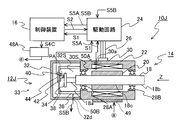
本実施形態のエンコーダ部12Jを備える駆動装置10Jを示す図7において、モータケース30の側面の貫通穴30aに、モータケース30内の空間30Sの温度を計測する温度センサ50Aが設けられ、エンコーダケース32の側面の貫通穴32dに、エンコーダケース32内の空間32Sの温度を計測する温度センサ50Bが設けられている。温度センサ50A,50Bで計測される空間30S,32Sの空気の温度を含む温度情報S5A,S5Bが駆動回路24及び制御装置16に供給されている。
本実施形態のエンコーダ部12Jを備える駆動装置10Jを示す図7において、モータケース30の側面の貫通穴30aに、モータケース30内の空間30Sの温度を計測する温度センサ50Aが設けられ、エンコーダケース32の側面の貫通穴32dに、エンコーダケース32内の空間32Sの温度を計測する温度センサ50Bが設けられている。温度センサ50A,50Bで計測される空間30S,32Sの空気の温度を含む温度情報S5A,S5Bが駆動回路24及び制御装置16に供給されている。
また、本実施形態では、エンコーダケース32にヒータは設けられていないが、モータケース30の外面に、モータケース30を冷却する冷却素子49が設けられている。冷却素子49としては、例えばペルチェ素子、又は冷却された液体をモータケース30の側面に設けられた配管を通して循環させる機構などが使用できる。制御装置16は吸熱量を示す吸熱指令情報S4Cを電源部48Aに供給し、それに応じて電源部48Aが冷却素子49に供給する電流を制御することで、冷却素子49が装着されたモータケース30内の空間30Sの温度が制御される。この他の構成は図1(B)の実施形態と同様である。
本実施形態において、制御装置16は、温度センサ50A,50Bで計測する空間30S,32Sの温度情報を用いて、一例として、エンコーダケース32内の空間32Sの温度がモータケース30内の空間30Sの温度よりも高くなるように、温度センサ50A,50B及び冷却素子49(調整機構)を用いてモータケース30の温度を低下させる。このとき、空間32Sの気圧が空間30Sの気圧よりも高くなり、空間30Sからの高湿度の空気の空間32Sへの流入を防止でき、エンコーダケース32内での結露を防止できる。
なお、本実施形態において、制御装置16は、空間32Sの温度と、空間30Sの温度とが実質的に同じになるように、冷却素子49の吸熱量を制御しても良い。実質的に同じとは、例えばモータケース30内からエンコーダケース32内に気体が侵入しない程度であれば、それらの温度が完全に一致していなくても良いことを意味する。この構成によれば、空間30Sの気体が軸受28Aを介して空間32Sに流入することを抑制することができる。
また、本実施形態において、制御装置16は、エンコーダケース32内の空間32Sの気圧又は温度が、それぞれ外気圧又は外気温よりも高くなるように制御してもよい。又は、空間32Sの気圧又は温度が、それぞれモータケース30内の空間30Sの気圧又は温度よりも高くなるように制御してもよい。
また、本実施形態において、上述の第1から第7の実施形態の気圧又は温度の調整機構を併用してもよい。
なお、上述の各実施形態及びその変形例の駆動装置10~10Jは各種工作機械又はロボット装置の駆動機構として使用できる。
また、本実施形態において、上述の第1から第7の実施形態の気圧又は温度の調整機構を併用してもよい。
なお、上述の各実施形態及びその変形例の駆動装置10~10Jは各種工作機械又はロボット装置の駆動機構として使用できる。
10,10A~10I…駆動装置、12,12A~12I…エンコーダ部、14…モータ部、16…制御装置、18…回転軸、18A…第1回転軸、18B…第2回転軸、22…コイル、24…駆動回路、28A,28B…回転軸受、30,30A,30B…モータケース、32,32A…エンコーダケース、34,34A,34B…回転板、40,40A,40B…光源、42,42A,42B…受光素子、44…処理回路、46…ヒータ、49…冷却素子、50…温度センサ、52A,52B…圧力計、56…加圧装置、58…減圧装置、60…冷却部材、66…減速機
Claims (23)
- 第1回転軸の回転情報を検出するエンコーダであって、
前記第1回転軸に設けられたパターンを検出する第1検出器と、
前記第1回転軸に設けられたパターン及び前記第1検出器を収容する第1収容ケースと、
前記第1回転軸のうち、前記パターンが設けられた部分とは異なる軸部の少なくとも一部を収容する第2収容ケースと、
前記第1収容ケース内の気圧と温度との少なくとも一方を前記第2収容ケース内の気圧と温度との少なくとも一方よりも高くする調整機構と、を備えるエンコーダ。 - 前記調整機構は、前記第2収容ケース内の気圧と温度との少なくとも一方に基づいて、前記第1収容ケース内の気圧と温度との少なくとも一方を調整する、請求項1に記載のエンコーダ。
- 前記調整機構は、前記第1収容ケース内の気体を加熱する加熱部を有する、請求項1又は2に記載のエンコーダ。
- 前記加熱部は、前記第1収容ケースに設けられる、請求項3に記載のエンコーダ。
- 前記調整機構は、前記第2収容ケース内の気体の温度を検出する温度センサを有し、
前記加熱部は、前記温度センサの検出結果を用いて加熱量を調整する請求項3又は請求項4に記載のエンコーダ。 - 前記調整機構は、前記第2収容ケース内の気圧を検出する圧力センサを有し、
前記加熱部は、前記圧力センサの検出結果を用いて加熱量を調整する請求項3から請求項5のいずれか一項に記載のエンコーダ。 - 前記調整機構は、前記第1収容ケース内の気圧と前記第2収容ケース内の気圧との一方に基づいて、前記第1収容ケース内の気圧と前記第2収容ケース内の気圧との他方を調整する請求項1に記載のエンコーダ。
- 前記調整機構は、前記第1収容ケース内に気体を供給し、前記第1収容ケース内を加圧する加圧部を有する、請求項7に記載のエンコーダ。
- 前記調整機構は、前記第1及び第2収容ケース内の気圧をそれぞれ検出する第1圧力センサ及び第2圧力センサを有し、
前記加圧部は、前記第1及び第2圧力センサの検出結果を用いて前記気体の供給量を調整する請求項8に記載のエンコーダ。 - 前記調整機構は、前記第2収容ケース内の気体を排気する減圧部と、前記第1及び第2収容ケース内の気圧をそれぞれ検出する第1圧力センサ及び第2圧力センサとを有し、
前記減圧部は、前記第1及び第2圧力センサの検出結果を用いて前記気体の排気量を調整する請求項7に記載のエンコーダ。 - 前記調整機構は、前記第2収容ケースに設けられて、前記第2収容ケース内の気体を排気可能な通気孔を有する請求項1から請求項10のいずれか一項に記載のエンコーダ。
- 前記検出器は、前記第1回転軸の一端部に取り付けられたスケールと、前記スケールの変位を検出する変位検出部とを有し、
前記パターンは、前記スケールに形成され、
前記調整機構は、前記第1収容ケース内に設けられ、かつ前記スケールよりも熱容量の大きい冷却部を有する請求項1から請求項11のいずれか一項に記載のエンコーダ。 - 前記第1回転軸に形成された中空部に第2回転軸が挿入され、
前記第2回転軸に設けられたパターンを検出する第2検出器を有し、
前記第1収容ケースは、前記第2回転軸に設けられたパターン及び前記第2検出器を収容する、請求項1から請求項12のいずれか一項に記載のエンコーダ。 - 請求項1から請求項13のいずれか一項に記載のエンコーダと、
前記第1回転軸を駆動するモータ部と、
前記エンコーダの検出結果を用いて前記モータ部を制御する制御部と、を備え、
前記第2収容ケースは、前記モータ部を収容する駆動装置。 - 請求項13に記載のエンコーダと、
前記第1回転軸を駆動するモータ部と、
前記第1回転軸の端部と前記第2回転軸の端部とを連結し、前記第1回転軸の回転を前記第2回転軸に伝達する伝達部と、
前記エンコーダの検出結果を用いて前記モータ部を制御する制御部と、を備え、
前記第2収容ケースは、前記モータ部を収容する駆動装置。 - 第1回転軸の回転情報を検出する第1エンコーダと、
前記第1エンコーダを収容する第1収容ケースと、
前記第1回転軸を駆動するモータ部と、
前記モータ部を収容する第2収容ケースと、
前記モータ部の運転を開始してから前記モータ部の温度が飽和するまでの間、前記第1収容ケース内の気圧と温度との少なくとも一方と、前記第2収容ケース内の気圧と温度と少なくとも一方とを互いに等しく、もしくは前記第1収容ケース内の気圧と温度との少なくとも一方を前記第2収容ケース内の気圧と温度との少なくとも一方よりも高く調整する調整機構と、を備える駆動装置。 - 前記調整機構は、前記第2収容ケース内の気圧と温度との少なくとも一方に基づいて、前記第1収容ケース内の気圧と温度との少なくとも一方を調整する、請求項16に記載の駆動装置。
- 前記調整機構は、前記第1収容ケース内の気体を加熱する加熱部を有する、請求項16又は17に記載の駆動装置。
- 前記加熱部は、前記第1収容ケースに設けられる、請求項18に記載の駆動装置。
- 前記調整機構は、前記第2収容ケース内の気体の温度を検出する温度センサを有し、
前記加熱部は、前記温度センサの検出結果を用いて加熱量を調整する請求項18又は19に記載の駆動装置。 - 前記調整機構は、前記第2収容ケース内の気圧を検出する圧力センサを有し、
前記加熱部は、前記圧力センサの検出結果を用いて加熱量を調整する請求項18から請求項20のいずれか一項に記載の駆動装置。 - 前記調整機構は、前記第1収容ケース内に気体を供給し、前記第1収容ケース内を加圧する加圧部を有する、請求項17又は18に記載の駆動装置。
- 前記調整機構は、前記第1及び第2収容ケース内の気圧をそれぞれ検出する第1圧力センサ及び第2圧力センサを有し、
前記加圧部は、前記第1及び第2圧力センサの検出結果を用いて前記気体の供給量を調整する請求項22に記載の駆動装置。
Priority Applications (3)
| Application Number | Priority Date | Filing Date | Title |
|---|---|---|---|
| US16/630,881 US12104932B2 (en) | 2017-07-14 | 2018-07-10 | Encoder and drive device |
| CN201880046613.5A CN110869711B (zh) | 2017-07-14 | 2018-07-10 | 编码器及驱动装置 |
| JP2019529731A JP7299565B2 (ja) | 2017-07-14 | 2018-07-10 | エンコーダ及び駆動装置 |
Applications Claiming Priority (2)
| Application Number | Priority Date | Filing Date | Title |
|---|---|---|---|
| JP2017137860 | 2017-07-14 | ||
| JP2017-137860 | 2017-07-14 |
Publications (1)
| Publication Number | Publication Date |
|---|---|
| WO2019013206A1 true WO2019013206A1 (ja) | 2019-01-17 |
Family
ID=65002095
Family Applications (1)
| Application Number | Title | Priority Date | Filing Date |
|---|---|---|---|
| PCT/JP2018/026034 Ceased WO2019013206A1 (ja) | 2017-07-14 | 2018-07-10 | エンコーダ及び駆動装置 |
Country Status (4)
| Country | Link |
|---|---|
| US (1) | US12104932B2 (ja) |
| JP (1) | JP7299565B2 (ja) |
| CN (1) | CN110869711B (ja) |
| WO (1) | WO2019013206A1 (ja) |
Cited By (2)
| Publication number | Priority date | Publication date | Assignee | Title |
|---|---|---|---|---|
| CN110290663A (zh) * | 2019-06-20 | 2019-09-27 | 深圳市洛丁光电有限公司 | 一种防水型通讯电气设备箱 |
| US20220349731A1 (en) * | 2017-07-14 | 2022-11-03 | Nikon Corporation | Encoder and drive device |
Citations (8)
| Publication number | Priority date | Publication date | Assignee | Title |
|---|---|---|---|---|
| JPS6488117A (en) * | 1987-09-29 | 1989-04-03 | Teijin Seiki Co Ltd | Casing for optical position sensor device |
| JPH05322597A (ja) * | 1992-05-20 | 1993-12-07 | Tamagawa Seiki Co Ltd | 光ファイバエンコーダ |
| JP2004198179A (ja) * | 2002-12-17 | 2004-07-15 | Yaskawa Electric Corp | 光学式エンコーダ |
| JP2006136160A (ja) * | 2004-11-08 | 2006-05-25 | Toshiba Elevator Co Ltd | 電動機システム |
| JP2011002311A (ja) * | 2009-06-18 | 2011-01-06 | Hitachi Ltd | 回転角検出装置および回転速度検出装置 |
| WO2013146371A1 (ja) * | 2012-03-30 | 2013-10-03 | 株式会社デンソーウェーブ | エンコーダ、エンコーダの取り付け方法、トルク制限機構、駆動装置及びロボット装置 |
| JP2015105602A (ja) * | 2013-11-29 | 2015-06-08 | 株式会社島津製作所 | 真空ポンプ装置および真空ポンプ装置システム |
| US20170077777A1 (en) * | 2015-09-11 | 2017-03-16 | Hyundai Motor Company | Totally enclosed motor |
Family Cites Families (43)
| Publication number | Priority date | Publication date | Assignee | Title |
|---|---|---|---|---|
| JPS5944640A (ja) * | 1982-09-08 | 1984-03-13 | Matsushita Electric Ind Co Ltd | 水蒸気暴露試験装置 |
| JPS61141672A (ja) * | 1984-12-14 | 1986-06-28 | 三菱マテリアル株式会社 | 切削工具用立方晶窒化硼素基焼結体の製造法 |
| JPH0376115U (ja) * | 1989-11-27 | 1991-07-30 | ||
| KR960005749U (ko) * | 1994-07-29 | 1996-02-17 | 공기조화기의 이슬맺힘 방지장치 | |
| JPH08201414A (ja) * | 1995-01-26 | 1996-08-09 | Nippon Telegr & Teleph Corp <Ntt> | 回転速度検出器 |
| DE10106012A1 (de) * | 2001-02-09 | 2002-08-14 | Heidenhain Gmbh Dr Johannes | Winkelmesseinrichtung |
| CN100472919C (zh) * | 2001-06-13 | 2009-03-25 | 日本电产三协株式会社 | 线性驱动装置 |
| CN2529245Y (zh) * | 2002-03-06 | 2003-01-01 | 邓梁 | 激光霜露点传感器 |
| JP2004293554A (ja) * | 2002-12-09 | 2004-10-21 | Matsushita Electric Ind Co Ltd | インバータ装置一体型電動圧縮機 |
| US7141965B2 (en) * | 2003-11-26 | 2006-11-28 | International Business Machines Corporation | Magnetic encoder system |
| US7196527B2 (en) * | 2004-02-17 | 2007-03-27 | Stridsberg Innovation Ab | Redundant compact encoders |
| WO2007062766A1 (de) * | 2005-12-01 | 2007-06-07 | Emb-Papst St. Georgen Gmbh & Co. Kg | Elektromotor |
| JP4787076B2 (ja) * | 2006-06-05 | 2011-10-05 | エスペック株式会社 | 湿度制御方法及び環境試験装置 |
| DE102006041056C5 (de) * | 2006-09-01 | 2015-02-19 | Siemens Aktiengesellschaft | Drehgeber zum Anschluss weiterer Sensoren sowie elektrische Maschine mit einem derartigen Drehgeber |
| CN101802631B (zh) * | 2007-09-10 | 2014-10-22 | Ntn株式会社 | 传感器组件 |
| JP5207171B2 (ja) * | 2008-03-05 | 2013-06-12 | カヤバ工業株式会社 | モータ |
| JP5314945B2 (ja) * | 2008-06-23 | 2013-10-16 | 日立オートモティブシステムズ株式会社 | 回転電機 |
| JP5096442B2 (ja) * | 2009-11-17 | 2012-12-12 | 株式会社日立製作所 | 回転角計測装置,モータシステム及び電動パワーステアリング・システム |
| CN102455190B (zh) * | 2010-10-23 | 2013-11-20 | 深圳市鑫汇科电子有限公司 | 一种磁感应式防水编码器 |
| KR101229449B1 (ko) * | 2011-02-14 | 2013-02-04 | 산일전기 주식회사 | 로터리 엔코더 |
| JP5883637B2 (ja) * | 2011-05-23 | 2016-03-15 | 株式会社ショーワ | 相対角度検出装置および電動パワーステアリング装置 |
| JP5427842B2 (ja) * | 2011-06-30 | 2014-02-26 | 日立オートモティブシステムズ株式会社 | 回転角計測装置,制御装置およびそれらを用いた回転機システム |
| JP5750325B2 (ja) * | 2011-07-15 | 2015-07-22 | 山洋電気株式会社 | エンコーダ |
| EP2775270A4 (en) * | 2011-10-31 | 2015-08-26 | Nsk Ltd | OPTICAL SENSOR, METHOD FOR PRODUCING OPTICAL SENSORS, OPTICAL ENCODER, TORQUE SENSING DEVICE, AND POWER ASSISTED STEERING DEVICE |
| CN103226152B (zh) * | 2012-01-27 | 2015-04-29 | 株式会社电装 | 旋转检测装置及其制造方法 |
| DE102012202683A1 (de) * | 2012-02-22 | 2013-08-22 | Dr. Johannes Heidenhain Gmbh | Drehgeber |
| JP6300431B2 (ja) * | 2012-04-27 | 2018-03-28 | キヤノン株式会社 | エンコーダ、レンズ装置、および、カメラ |
| US9182070B2 (en) * | 2012-04-30 | 2015-11-10 | Threat Spectrum Inc. | Positioning device |
| JP5895774B2 (ja) * | 2012-09-04 | 2016-03-30 | 株式会社安川電機 | モータ |
| JP2014163779A (ja) * | 2013-02-25 | 2014-09-08 | Yoshiharu Maruyama | 耐環境試験方法 |
| US9227439B1 (en) * | 2014-06-18 | 2016-01-05 | Eastman Kodak Company | Printers having encoders for monitoring paper misalignments |
| US9797753B1 (en) * | 2014-08-27 | 2017-10-24 | Apple Inc. | Spatial phase estimation for optical encoders |
| JP2016070668A (ja) * | 2014-09-26 | 2016-05-09 | 日本精工株式会社 | 小型エンコーダ |
| JP6491456B2 (ja) * | 2014-10-29 | 2019-03-27 | 日本電産シンポ株式会社 | トラクション動力伝達装置 |
| US9651405B1 (en) * | 2015-03-06 | 2017-05-16 | Apple Inc. | Dynamic adjustment of a sampling rate for an optical encoder |
| JP6499532B2 (ja) | 2015-06-30 | 2019-04-10 | ファナック株式会社 | 吸湿剤の吸湿量を取得する機能を備えた回転エンコーダ |
| TWI552116B (zh) * | 2015-09-10 | 2016-10-01 | Condensation prevention and treatment methods | |
| FR3042327B1 (fr) * | 2015-10-07 | 2019-08-02 | Guillemot Corporation | Systeme de refroidissement d'un moteur electrique |
| DE102016115624A1 (de) * | 2016-08-23 | 2018-03-01 | Fraba B.V. | Verfahren zum Kalibrieren eines Drehgebers und Drehgeber |
| JP6404988B1 (ja) * | 2017-04-20 | 2018-10-17 | ファナック株式会社 | エンコーダ |
| CN110869711B (zh) * | 2017-07-14 | 2022-02-15 | 株式会社尼康 | 编码器及驱动装置 |
| JP7121341B2 (ja) * | 2018-10-04 | 2022-08-18 | 株式会社ニコン | エンコーダ及び駆動装置、並びに加熱方法 |
| DE102021005044B4 (de) * | 2021-10-08 | 2024-07-11 | Baumer Germany Gmbh & Co. Kg | Messdatenprozessor, Positionsmessgerät und computerimplementiertes Verfahren |
-
2018
- 2018-07-10 CN CN201880046613.5A patent/CN110869711B/zh active Active
- 2018-07-10 US US16/630,881 patent/US12104932B2/en active Active
- 2018-07-10 WO PCT/JP2018/026034 patent/WO2019013206A1/ja not_active Ceased
- 2018-07-10 JP JP2019529731A patent/JP7299565B2/ja active Active
Patent Citations (8)
| Publication number | Priority date | Publication date | Assignee | Title |
|---|---|---|---|---|
| JPS6488117A (en) * | 1987-09-29 | 1989-04-03 | Teijin Seiki Co Ltd | Casing for optical position sensor device |
| JPH05322597A (ja) * | 1992-05-20 | 1993-12-07 | Tamagawa Seiki Co Ltd | 光ファイバエンコーダ |
| JP2004198179A (ja) * | 2002-12-17 | 2004-07-15 | Yaskawa Electric Corp | 光学式エンコーダ |
| JP2006136160A (ja) * | 2004-11-08 | 2006-05-25 | Toshiba Elevator Co Ltd | 電動機システム |
| JP2011002311A (ja) * | 2009-06-18 | 2011-01-06 | Hitachi Ltd | 回転角検出装置および回転速度検出装置 |
| WO2013146371A1 (ja) * | 2012-03-30 | 2013-10-03 | 株式会社デンソーウェーブ | エンコーダ、エンコーダの取り付け方法、トルク制限機構、駆動装置及びロボット装置 |
| JP2015105602A (ja) * | 2013-11-29 | 2015-06-08 | 株式会社島津製作所 | 真空ポンプ装置および真空ポンプ装置システム |
| US20170077777A1 (en) * | 2015-09-11 | 2017-03-16 | Hyundai Motor Company | Totally enclosed motor |
Cited By (3)
| Publication number | Priority date | Publication date | Assignee | Title |
|---|---|---|---|---|
| US20220349731A1 (en) * | 2017-07-14 | 2022-11-03 | Nikon Corporation | Encoder and drive device |
| US12104932B2 (en) * | 2017-07-14 | 2024-10-01 | Nikon Corporation | Encoder and drive device |
| CN110290663A (zh) * | 2019-06-20 | 2019-09-27 | 深圳市洛丁光电有限公司 | 一种防水型通讯电气设备箱 |
Also Published As
| Publication number | Publication date |
|---|---|
| CN110869711B (zh) | 2022-02-15 |
| JPWO2019013206A1 (ja) | 2020-05-07 |
| JP7299565B2 (ja) | 2023-06-28 |
| US20220349731A1 (en) | 2022-11-03 |
| CN110869711A (zh) | 2020-03-06 |
| US12104932B2 (en) | 2024-10-01 |
Similar Documents
| Publication | Publication Date | Title |
|---|---|---|
| US6644938B2 (en) | Turbo molecular pump | |
| US20110200460A1 (en) | Vacuum pump | |
| US6508614B1 (en) | Spindle device and machine tool utilizing the same | |
| JP7273712B2 (ja) | 高速回転機用赤外線温度センサ | |
| JP2009068533A (ja) | 軸受装置 | |
| JP7299565B2 (ja) | エンコーダ及び駆動装置 | |
| EP2672351B1 (en) | Positioning device | |
| JPH11132867A (ja) | 温度モニタ装置 | |
| CN114207305B (zh) | 轴承装置和主轴装置 | |
| BR102016029093A2 (pt) | Method and mounting system for mounting a rotor in a stator | |
| JP7121341B2 (ja) | エンコーダ及び駆動装置、並びに加熱方法 | |
| JP3847796B2 (ja) | バックアップ軸受装置を備えた真空ポンプ | |
| JP2009014136A (ja) | 磁気軸受装置 | |
| JP2017203689A (ja) | 疲労・耐久試験装置 | |
| JP2006177793A (ja) | シース型計測器及び軸受、並びに回転機械 | |
| JP5117038B2 (ja) | ロータにおける非接触式温度測定装置 | |
| JP6881133B2 (ja) | 真空用軸受の振動測定装置 | |
| KR101905087B1 (ko) | 볼스크류를 구비한 공작기계의 열변위 방지장치 및 열변위 방지방법 | |
| JP7208948B2 (ja) | 温度を算出するための方法 | |
| JP2007089312A (ja) | モータ回転軸の角度検出装置 | |
| JP2020003027A (ja) | 軸受装置 | |
| WO2015005093A1 (ja) | 温度検出ツール | |
| JP2009074925A (ja) | 温度センサの較正方法 | |
| JP3746630B2 (ja) | スピンドル装置 | |
| JP2002005164A (ja) | スピンドル装置 |
Legal Events
| Date | Code | Title | Description |
|---|---|---|---|
| 121 | Ep: the epo has been informed by wipo that ep was designated in this application |
Ref document number: 18831790 Country of ref document: EP Kind code of ref document: A1 |
|
| ENP | Entry into the national phase |
Ref document number: 2019529731 Country of ref document: JP Kind code of ref document: A |
|
| NENP | Non-entry into the national phase |
Ref country code: DE |
|
| 122 | Ep: pct application non-entry in european phase |
Ref document number: 18831790 Country of ref document: EP Kind code of ref document: A1 |