WO2019004359A1 - 成膜装置 - Google Patents
成膜装置 Download PDFInfo
- Publication number
- WO2019004359A1 WO2019004359A1 PCT/JP2018/024599 JP2018024599W WO2019004359A1 WO 2019004359 A1 WO2019004359 A1 WO 2019004359A1 JP 2018024599 W JP2018024599 W JP 2018024599W WO 2019004359 A1 WO2019004359 A1 WO 2019004359A1
- Authority
- WO
- WIPO (PCT)
- Prior art keywords
- substrate
- holding
- glass substrate
- film
- forming apparatus
- Prior art date
- Legal status (The legal status is an assumption and is not a legal conclusion. Google has not performed a legal analysis and makes no representation as to the accuracy of the status listed.)
- Ceased
Links
Images


Classifications
-
- H—ELECTRICITY
- H01—ELECTRIC ELEMENTS
- H01J—ELECTRIC DISCHARGE TUBES OR DISCHARGE LAMPS
- H01J37/00—Discharge tubes with provision for introducing objects or material to be exposed to the discharge, e.g. for the purpose of examination or processing thereof
- H01J37/32—Gas-filled discharge tubes
- H01J37/32431—Constructional details of the reactor
- H01J37/32715—Workpiece holder
-
- C—CHEMISTRY; METALLURGY
- C23—COATING METALLIC MATERIAL; COATING MATERIAL WITH METALLIC MATERIAL; CHEMICAL SURFACE TREATMENT; DIFFUSION TREATMENT OF METALLIC MATERIAL; COATING BY VACUUM EVAPORATION, BY SPUTTERING, BY ION IMPLANTATION OR BY CHEMICAL VAPOUR DEPOSITION, IN GENERAL; INHIBITING CORROSION OF METALLIC MATERIAL OR INCRUSTATION IN GENERAL
- C23C—COATING METALLIC MATERIAL; COATING MATERIAL WITH METALLIC MATERIAL; SURFACE TREATMENT OF METALLIC MATERIAL BY DIFFUSION INTO THE SURFACE, BY CHEMICAL CONVERSION OR SUBSTITUTION; COATING BY VACUUM EVAPORATION, BY SPUTTERING, BY ION IMPLANTATION OR BY CHEMICAL VAPOUR DEPOSITION, IN GENERAL
- C23C14/00—Coating by vacuum evaporation, by sputtering or by ion implantation of the coating forming material
- C23C14/22—Coating by vacuum evaporation, by sputtering or by ion implantation of the coating forming material characterised by the process of coating
- C23C14/50—Substrate holders
-
- C—CHEMISTRY; METALLURGY
- C23—COATING METALLIC MATERIAL; COATING MATERIAL WITH METALLIC MATERIAL; CHEMICAL SURFACE TREATMENT; DIFFUSION TREATMENT OF METALLIC MATERIAL; COATING BY VACUUM EVAPORATION, BY SPUTTERING, BY ION IMPLANTATION OR BY CHEMICAL VAPOUR DEPOSITION, IN GENERAL; INHIBITING CORROSION OF METALLIC MATERIAL OR INCRUSTATION IN GENERAL
- C23C—COATING METALLIC MATERIAL; COATING MATERIAL WITH METALLIC MATERIAL; SURFACE TREATMENT OF METALLIC MATERIAL BY DIFFUSION INTO THE SURFACE, BY CHEMICAL CONVERSION OR SUBSTITUTION; COATING BY VACUUM EVAPORATION, BY SPUTTERING, BY ION IMPLANTATION OR BY CHEMICAL VAPOUR DEPOSITION, IN GENERAL
- C23C14/00—Coating by vacuum evaporation, by sputtering or by ion implantation of the coating forming material
- C23C14/22—Coating by vacuum evaporation, by sputtering or by ion implantation of the coating forming material characterised by the process of coating
- C23C14/34—Sputtering
-
- C—CHEMISTRY; METALLURGY
- C23—COATING METALLIC MATERIAL; COATING MATERIAL WITH METALLIC MATERIAL; CHEMICAL SURFACE TREATMENT; DIFFUSION TREATMENT OF METALLIC MATERIAL; COATING BY VACUUM EVAPORATION, BY SPUTTERING, BY ION IMPLANTATION OR BY CHEMICAL VAPOUR DEPOSITION, IN GENERAL; INHIBITING CORROSION OF METALLIC MATERIAL OR INCRUSTATION IN GENERAL
- C23C—COATING METALLIC MATERIAL; COATING MATERIAL WITH METALLIC MATERIAL; SURFACE TREATMENT OF METALLIC MATERIAL BY DIFFUSION INTO THE SURFACE, BY CHEMICAL CONVERSION OR SUBSTITUTION; COATING BY VACUUM EVAPORATION, BY SPUTTERING, BY ION IMPLANTATION OR BY CHEMICAL VAPOUR DEPOSITION, IN GENERAL
- C23C14/00—Coating by vacuum evaporation, by sputtering or by ion implantation of the coating forming material
- C23C14/22—Coating by vacuum evaporation, by sputtering or by ion implantation of the coating forming material characterised by the process of coating
- C23C14/56—Apparatus specially adapted for continuous coating; Arrangements for maintaining the vacuum, e.g. vacuum locks
- C23C14/564—Means for minimising impurities in the coating chamber such as dust, moisture, residual gases
-
- H—ELECTRICITY
- H10—SEMICONDUCTOR DEVICES; ELECTRIC SOLID-STATE DEVICES NOT OTHERWISE PROVIDED FOR
- H10P—GENERIC PROCESSES OR APPARATUS FOR THE MANUFACTURE OR TREATMENT OF DEVICES COVERED BY CLASS H10
- H10P72/00—Handling or holding of wafers, substrates or devices during manufacture or treatment thereof
- H10P72/70—Handling or holding of wafers, substrates or devices during manufacture or treatment thereof for supporting or gripping
-
- H—ELECTRICITY
- H01—ELECTRIC ELEMENTS
- H01J—ELECTRIC DISCHARGE TUBES OR DISCHARGE LAMPS
- H01J2237/00—Discharge tubes exposing object to beam, e.g. for analysis treatment, etching, imaging
- H01J2237/20—Positioning, supporting, modifying or maintaining the physical state of objects being observed or treated
- H01J2237/2007—Holding mechanisms
-
- H—ELECTRICITY
- H01—ELECTRIC ELEMENTS
- H01J—ELECTRIC DISCHARGE TUBES OR DISCHARGE LAMPS
- H01J2237/00—Discharge tubes exposing object to beam, e.g. for analysis treatment, etching, imaging
- H01J2237/32—Processing objects by plasma generation
- H01J2237/33—Processing objects by plasma generation characterised by the type of processing
- H01J2237/332—Coating
Definitions
- the present invention relates to a film forming apparatus, and more particularly to a technique suitable for use in film formation such as sputtering and CVD.
- a technique suitable for use in film formation such as sputtering and CVD.
- a sputtering apparatus In the semiconductor device field or flat panel display (FPD) field, a sputtering apparatus is used as an apparatus for forming various thin films.
- a cathode for sputtering In a general sputtering apparatus, a cathode for sputtering is provided in a chamber, and an object to be processed (substrate) is disposed to face a target attached to the cathode at a predetermined distance in a reduced pressure chamber. Ru.
- Ar gas inert gas
- a negative voltage is applied to the target in a state where the object to be treated is connected to the ground to cause discharge, and Ar ions ionized from Ar gas by discharge are Make it hit the target.
- the film-forming process is performed by making the to-be-processed object the particle
- Patent Document 1 As an example of such an apparatus, as described in Patent Document 1, there has been known a technique of forming a film while the substrate is positioned and supported by a clamp mechanism.
- a process with a large amount of film formation may be performed, such as continuously performing a plurality of types of film formation processes.
- the deposit is deposited on the clamp mechanism which is a movable part in the deposition chamber, the amount of the deposit increases, and the deposit becomes a particle generation source which causes a deposition defect. For this reason, there has been a demand for not providing a clamp mechanism.
- the present invention has been made in view of the above circumstances, and aims to achieve the following objects. 1. Even if the amount of film formation is increased, the generation of particles can be reduced. 2. Maintaining the accuracy of substrate alignment in film formation processing.
- a film forming apparatus is a film forming apparatus for forming a film on a substrate to be processed, which is disposed in a chamber that can be evacuated and supplies a film forming material; And a holding device for holding the substrate to be processed.
- the holding device includes an adhesion preventing plate for covering a region to which the film forming material is attached in the holding device, a holding portion for holding the substrate to be processed, the adhesion preventing plate and the holding portion include the substrate to be treated.
- a position setting unit configured to set the position of the processing target substrate when holding and holding.
- the position setting unit has a roller that abuts on a peripheral end surface of the substrate to be processed.
- the position setting unit may be provided at a position to abut on each of the edges of the processing target substrate located at mutually opposite positions.
- a driving device may be provided outside the chamber.
- the roller may be provided on the adhesion preventing plate.
- the roller may be provided in the holding unit.
- the holding device may have a support member that abuts on a peripheral end surface of the target substrate.
- the support member may be provided on the adhesion preventing plate.
- the support member has a substrate support portion in contact with at least the peripheral end face portion of the target substrate, and the substrate support portion extends along the surface of the target substrate. It may be movable in the normal direction of the peripheral end face portion in the vertical direction, and may be biased toward the center of the processing substrate.
- a film forming apparatus is a film forming apparatus for forming a film on a substrate to be processed, which is disposed in a chamber that can be evacuated and supplies a film forming material; And a holding device for holding the substrate to be processed.
- the holding device includes an adhesion preventing plate for covering a region to which the film forming material is attached in the holding device, a holding portion for holding the substrate to be processed, the adhesion preventing plate and the holding portion include the substrate to be treated.
- a position setting unit configured to set the position of the processing target substrate when holding and holding.
- the position setting unit has a roller that abuts on a peripheral end surface of the substrate to be processed.
- the peripheral end face of the substrate to be treated abuts against the roller by the movement of the adhesion preventing plate and the holding portion close to each other. It is positioned so as to be at a predetermined position with respect to the plate. As a result, positioning is performed without damage to the substrate to be processed with the peripheral end face portion abutted by the rotating roller only by the operation in which the adhesion preventing plate and the holding portion approach each other. Therefore, the film formation process can be performed on the target substrate in a state of being accurately positioned.
- the position setting unit in the holding device, is provided at a position that abuts on each of the edge portions of the processing target substrates located at mutually opposite positions.
- the position setting portion abuts on each of the edges of the substrate to be processed opposite to each other, and the substrate to be processed can be positioned to be in a predetermined position with respect to the adhesion preventing plate.
- the plurality of position setting portions are provided in the holding device such that the position setting portions abut on each of the edge portions positioned on the sides of the processing target substrates intersecting with each other. Is preferred.
- the substrate to be processed can be positioned in a plurality of directions in the in-plane direction of the substrate to be processed.
- the adhesion preventing plate and the holding portion sandwich and hold the target substrate, the adhesion preventing plate and the holding portion are separated and brought close to each other.
- a drive is provided outside the chamber.
- the roller is provided on the adhesion preventing plate.
- the substrate to be processed can be accurately positioned at a position corresponding to the arrangement position of the rollers in the adhesion preventing plate by the movement of the adhesion preventing plate and the holding portion approaching each other when sandwiching the substrate to be treated .
- the roller is provided in the holding unit.
- the substrate to be processed is positioned at a position corresponding to the arrangement position of the roller in the holding unit by the movement of the adhesion preventing plate and the holding unit approaching each other when holding the substrate to be processed, and the holding unit corresponds to the holding unit. It is possible to set the position of the substrate to be processed with respect to the adhesion prevention plate that is set.
- the holding device has a support member that abuts on a peripheral end surface of the substrate to be processed. As a result, even when the support substrate is supported by bringing the support member into contact with the peripheral end surface of the process substrate, the occurrence of breakage or the like can be prevented at the edge of the process substrate.
- the support member is provided on the anti-adhesion plate.
- the substrate to be processed can be supported at a position corresponding to the arrangement position of the support member in the adhesion prevention plate.
- the substrate to be treated can be supported so that the position of the substrate to be treated relative to the deposition preventing plate does not change during the film forming process.
- the support member has a substrate support portion in contact with at least the peripheral end face portion of the target substrate, and the substrate support portion extends along the surface of the target substrate. While being movable in the normal direction of the peripheral end face portion in the vertical direction, it is biased toward the center of the processing substrate. This can prevent the occurrence of cracking or chipping at the edge of the substrate to be treated.
- urging toward the center of a to-be-processed substrate means the direction which can support the load of the to-be-processed substrate applied to a substrate support part.
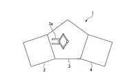
- FIG. 1 is a schematic plan view showing a film forming apparatus according to the present embodiment.
- FIG. 2 is a schematic side view showing a load / unload chamber of the film forming apparatus according to the present embodiment.
- FIG. 3 is a schematic side view showing a film forming chamber of the film forming apparatus according to the present embodiment.
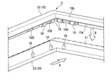
- FIG. 4 is a perspective view showing the holding device of the film forming apparatus according to the present embodiment.
- symbol 1 is a film-forming apparatus.
- the film forming apparatus 1 is, for example, a case where a TFT (Thin Film Transistor) is formed on a target substrate (glass substrate, substrate) made of glass or the like in a manufacturing process of a liquid crystal display.
- the substrate processing apparatus is an interback type or in-line type vacuum processing apparatus that performs heat processing, film formation processing, etching processing, and the like in a vacuum environment on a substrate to be processed made of glass or resin.
- the film forming apparatus 1 includes, for example, a load / unload chamber 2 for carrying in / out a glass substrate 11 (substrate to be treated) made of substantially rectangular glass, and a glass substrate 11. Between the film forming chamber 4 and the load / unload chamber 2 (chamber), a pressure-resistant film forming chamber 4 (chamber) in which a film such as a ZnO or In 2 O 3 transparent conductive film is formed by sputtering And a transfer chamber 3 (chamber) located at As shown in FIG.
- a sputter-down type sputtering apparatus is employed as the film forming apparatus 1 according to the present embodiment, but it is also possible to adopt a side-sputtering type sputtering apparatus or a sputter-up type sputtering apparatus. it can.
- a plurality of chambers may be formed to surround the transfer chamber 3.
- Such a chamber may be, for example, composed of two load / unload chambers (chambers) formed adjacent to each other and a plurality of processing chambers (chambers).
- one load / unload chamber loads the glass substrate 11 from the outside toward the vacuum processing apparatus (film forming apparatus 1), and the other load / unload chamber.
- the chamber may be an unloading chamber for unloading the glass substrate 11 from the film forming apparatus 1 to the outside.
- a partition valve may be formed between each of the chambers 2 and 4 and the transfer chamber 3 and between the load / unload chamber 2 (chamber) and the outside.
- a positioning member 2a capable of setting and positioning the mounting position of the glass substrate 11 carried in from the outside of the film forming apparatus 1 is disposed.
- the load / unload chamber 2 is also provided with a roughing exhaust device 2 b (low vacuum exhaust device) such as a rotary pump for roughly evacuating the inside of the load / unload chamber 2.
- a roughing exhaust device 2 b low vacuum exhaust device
- a transfer device 3a (transfer robot) is disposed inside the transfer chamber 3, as shown in FIG. 1, a transfer device 3a (transfer robot) is disposed.
- the transfer device 3a has a rotation shaft, a robot arm attached to the rotation shaft, a robot hand formed at one end of the robot arm, and a vertical movement device for moving the robot hand up and down.
- the robot arm is composed of first and second active arms which can be bent relative to each other, and first and second driven arms.
- the transfer device 3 a can move the glass substrate 11 as the transferred object between each of the chambers 2 and 4 and the transfer chamber 3.
- a holding device 10 for holding the glass substrate 11 during film formation is provided inside the film forming chamber 4, as shown in FIG. 3, a holding device 10 for holding the glass substrate 11 during film formation is provided.
- the holding device 10 may include a heater for heating the glass substrate 11.
- a backing plate 6 (cathode electrode, sputter cathode) functioning as a supply device for supplying a film forming material is provided upright at a position facing the heater, and sputtering of negative potential on the backing plate 6
- a power supply 7 for applying a voltage, a gas introduction unit 8 for introducing a gas into the film forming chamber 4, and a high vacuum exhausting device 9 such as a turbo molecular pump for drawing a high vacuum inside the film forming chamber 4 are provided. It is done.
- a target is fixed on the front side of the backing plate 6 facing substantially parallel to the glass substrate 11.
- a driving device 30 is provided outside the film forming chamber 4 to separate the adhesion preventing plate 15 and the holding portion 13 of the holding device 10 from each other and to approach each other.
- the drive device 30 is connected to the deposition prevention plate 15, and the relative distance between the deposition prevention plate 15 and the holding portion 13 is controlled by the drive device 30.
- the driving device 30 may be connected to the holding portion 13 without being connected to the adhesion preventing plate 15.
- the drive device 30 may be connected to both the adhesion prevention plate 15 and the holding portion 13.
- FIG. 5 is a cross-sectional view showing the structure in the vicinity of the position setting portion of the holding device in the present embodiment.
- FIG. 6 is a cross-sectional view showing a substrate guide of the holding device in the present embodiment.
- FIG. 5 is a cross-sectional view taken along the line VV in FIG. 4 and is a view showing a state in which the glass substrate is held between the adhesion preventing plate and the holding portion.
- FIG. 6 is a cross-sectional view taken along the line VI-VI in FIG. 4 and shows a state in which the glass substrate is held between the adhesion preventing plate and the holding portion. As shown in FIGS.
- the holding device 10 holds the holding portion 13 for holding the back surface 11L of the glass substrate 11, the edge 11E of the glass substrate 11, and the region R to which the film forming material in the holding device 10 adheres.
- a cover 16 and a roller 16 position setting unit for setting the position of the glass substrate 11 when the adhesion prevention plate 15 and the holding portion 13 sandwich and hold the glass substrate 11 and the periphery of the glass substrate 11
- a substrate guide 100 supporting member
- the holding portion 13 has a structure for supporting the peripheral portion (edge portion 11E) of the glass substrate 11 from the back surface 11L of the processing surface 11a (front surface) at the time of film formation processing of the glass substrate 11. It has a slightly larger frame shape.
- a heater (not shown) is disposed inside the frame-like holding portion 13. The heater can heat the glass substrate 11 supported by the holding unit 13 from the back surface 11L.
- the holding portion 13 includes a plurality of support convex portions 19 that contact the back surface 11L of the glass substrate 11 to support the glass substrate 11.
- the plurality of support convex portions 19 protrude from the surface (the surface facing the adhesion preventing plate 15) of the holding portion 13 toward the back surface 11 L (supporting side) of the glass substrate 11.
- the plurality of support protrusions 19 are arranged to correspond to the shape of the outer contour of the glass substrate 11.
- the support convex portion 19 is formed of a resin having heat resistance and vacuum resistance to a process such as sputtering and having a strength capable of supporting the glass substrate 11 as in the case of the roller 16 described later.
- a resin polyimide resins, such as Veespel (the DuPont company make, registered trademark) etc. are mentioned, for example.
- Each of the plurality of rollers 16 provided in the holding portion 13 is an extension of a linear portion 13X (a first linear portion, a side) or a linear portion 13Y (a second linear portion, a side) forming a frame of the holding portion 13 It has an axis parallel to the direction.
- Each of the rollers 16 is rotatable about this axis. Specifically, as shown in FIG. 4 and FIG. 5, the tangent TL (the tangent perpendicular to the axis and parallel to the holding portion 13) of the curved surface 16F of each roller 16 is directed toward the center of the holding portion 13.
- a plurality of rollers 16 are disposed on the straight portions 13X and 13Y of the holding portion 13 so as to extend.
- the plurality of rollers 16 can be rotated by an axis parallel to the peripheral end surface 11 b of the glass substrate 11 held by the holding unit 13, and the rotation curved surface 16 F of the roller 16 is the peripheral end surface 11 b of the glass substrate 11. It becomes possible to abut on.
- each of the plurality of rollers 16 can be provided at a position (both sides of the corner C) in the vicinity of the corner C which is a portion where the straight portions 13X and 13Y in the rectangular holding portion 13 intersect (connect). .
- the roller 16 is positioned at each of two pairs of linear portions (sides) opposed to each other, that is, two linear portions 13 ⁇ / b> X and two linear portions 13 ⁇ / b> Y.
- the arrangement of the plurality of rollers 16 and the number of the plurality of rollers 16 in the holding portion 13 may be appropriately set depending on the shape and size of the outer contour of the glass substrate 11 and the support state of the glass substrate 11 during processing. it can.
- rollers 16 are disposed on both sides of the corner C where two adjacent sides of the holding portion 13 connect, that is, at positions adjacent to the corner C where the straight portions 13X and 13Y connect. be able to. That is, 8 to 16 rollers 16 in total can be arranged in the four corner regions constituting the holding portion 13. Further, the rollers 16 can be disposed at positions on both sides of the support convex portion 19 in the direction in which the linear portions 13X and 13Y of the holding portion 13 extend.
- the roller 16 has its rotational curved surface 16F in contact with the peripheral end face 11b of the glass substrate 11 to set the in-plane supporting position of the glass substrate 11 with respect to the holding portion 13 Do. Further, the roller 16 and the support convex portion are disposed so that the rotation axis 16a of the roller 16 is located between the plane 11Va extending the surface 11a of the glass substrate 11 in the supported state and the plane 11VL extending the back surface 11L.
- the 19 positions are set. That is, the position of the rotation axis 16 a of the roller 16 is at a distance of about half the thickness dimension of the glass substrate 11 from the tip 19 T of the support convex portion 19 in the thickness direction of the glass substrate 11 in the supported state. .
- the dimension (diameter) in the radial direction of the roller 16 may be larger than the thickness dimension of the glass substrate 11, but for example, the diameter of the roller 16 can be three or more times the thickness dimension of the glass substrate 11.
- the roller 16 is formed of a resin having heat resistance and vacuum resistance against processing such as sputtering and having a strength capable of supporting the glass substrate 11.
- a resin having heat resistance and vacuum resistance against processing such as sputtering and having a strength capable of supporting the glass substrate 11.
- polyimide resins such as Veespel (the DuPont company make, registered trademark) etc. are mentioned, for example.
- the adhesion preventing plate 15 faces the holding portion 13, and holds and holds the glass substrate 11 together with the holding portion 13.
- the adhesion preventing plate 15 is a rectangle for covering the region R where the film forming material in the holding device 10 is not desired to be attached and the non-filming region (edge portion 11E) of the periphery of the glass substrate 11 supported by the holding portion 13 It is formed in a frame shape.
- the adhesion preventing plate 15 is provided to cover the portion from the outer peripheral portion of the holding device 10 to the outer peripheral portion of the glass substrate 11, and the adhesion preventing plate 15 is knocked out of the target of the backing plate 6. It is provided so as to cover the area where the particles adhere to other than the glass substrate 11.
- the film-forming material penetrates in the thickness direction of the adhesion preventing plate 15 so that the film forming material reaches the surface 11 a (surface) of the glass substrate 11 as shown in FIGS.
- An opening 15a is formed.
- an inclined portion 15b is formed.
- the inclined portion 15 b has an inclined surface such that the thickness of the inclined portion 15 b decreases in the direction from the outside to the center of the glass substrate 11. That is, the opening 15a is formed so that the opening area of the opening 15a is reduced in the direction from the front surface side to the back surface side of the adhesion preventing plate 15, whereby the inner peripheral surface of the opening 15a is formed.
- the inclined portion 15 b is formed.
- a recess 15 c corresponding to the shape of the roller 16 is formed on the back surface 15 L (back surface) of the adhesion preventing plate 15.
- the surface of the roller 16 facing the adhesion preventing plate 15 is positioned in the recess 15 c so that the roller 16 does not contact the adhesion preventing plate 15.
- the adhesion preventing plate 15 is provided in parallel to the holding portion 13 as shown in FIG. 4, and the adhesion preventing plate 15 and the holding portion 13 are separated and brought close to each other, thereby the adhesion preventing plate 15 and the holding portion It is provided so that the distance which 13 separates may become variable. At this time, the separation distance changes in the direction indicated by the arrow B in FIG. 4 while maintaining the parallel state between the adhesion preventing plate 15 and the holding portion 13.
- the holding device 10 is drivable so as to change the distance between the adhesion prevention plate 15 and the holding portion 13, and holds the glass substrate 11 between the adhesion prevention plate 15 and the holding portion 13 to hold and release the glass substrate 11. Can.
- the driving device 30 for driving the adhesion preventing plate 15 is provided.
- a driving device 30 for driving the deposition prevention plate 15 is provided at an outer position of the film forming chamber 4 (chamber).
- the distance between the holding portion 13 and the adhesion preventing plate 15 can be set by a drive pin (driving device) or the like extending in the normal direction of the adhesion preventing plate 15 and the holding portion 13.
- the drive pin can be configured to be advanced and retracted by a drive device 30 such as a drive motor disposed outside the film forming chamber 4 (chamber).
- the drive pin and the drive device 30 can drive the adhesion preventing plate 15 in a state in which the chamber 4 is kept sealed.
- the adhesion preventing plate 15 can be, for example, a rectangular plate made of titanium, ceramic, or the like configured to be attachable to and detachable from the holding portion 13.
- the attachment / detachment plate 15 is provided with an attachment / detachment bar extending along the normal direction of the frame-like adhesion prevention plate 15 on the back surface 15L (surface close to the glass substrate 11). Can.
- the attachment / detachment bar may be connected to the position regulating member that regulates the movement of the adhesion preventing plate 15 of the holding device 10 via the coupling member.
- the detachable bar is a cylindrical member provided along the normal direction of the adhesion preventing plate 15 and is received by the accommodating portion provided in the position regulating member.
- the transfer device 3 a transfer robot
- the adhesion preventing plate 15 can be taken out of the chambers 2, 3, 4.
- a plurality of substrate guides 100 (supporting members) located at the periphery of the opening 15a are provided.
- the substrate guide 100 has a base 110, a substrate support portion 120, and a coil spring 140 (biasing member), as shown in FIG.
- the base 110 and the substrate support portion 120 are formed of a resin having heat resistance and vacuum resistance against processing such as sputtering and having a strength capable of supporting the glass substrate 11.
- a resin such as polyimide resins, such as Veespel (the DuPont company make, registered trademark) etc. are mentioned, for example.
- the base 110 is attached to the back surface side 15 L of the adhesion preventing plate 15, and accommodates the substrate support portion 120 in contact with the glass substrate 11.
- the substrate support portion 120 is housed in the base 110 such that the support flat portion 121 protrudes from the center of the base 110 in the normal direction of the peripheral end surface portion 11 b of the glass substrate 11.
- the support flat portion 121 of the substrate support portion 120 contacts the peripheral end surface portion 11 b of the glass substrate 11 held by the holding device 10 substantially in parallel.
- the substrate support portion 120 is attached to the base 110 so as to be movable in the in-plane direction along the front surface 11 a and the back surface 11 L of the glass substrate 11, that is, in the normal direction of the peripheral end surface portion 11 b.
- the substrate supporting portion 120 is accommodated in the base 110, and the coil spring 140 with respect to the base 110 makes the normal direction of the peripheral end surface portion 11 b of the glass substrate 11, that is, the normal of the opening 15 a of the adhesion preventing plate 15. It is biased along the direction.
- the base 110 has a substantially rectangular parallelepiped shape.
- An internal space 111 in which the substrate support portion 120 is accommodated is formed in the base 110.
- the internal space 111 of the base 110 has openings 111a and 111b.
- the opening 111 a is opened at the back surface 110 a attached to the back surface 15 L of the adhesion preventing plate 15.
- the opening 111 b is opened to the inside of the opening 15 a of the adhesion preventing plate 15.
- On the back surface 110 a of the base 110 a plate-like contact portion 112 formed to extend along the extension direction of the back surface 110 a is provided upright.
- the internal space 111 of the base 110 has a substantially rectangular cross section in a rear view.
- This cross section is a substantially rectangular cross section in which almost the entire internal space 111 is opened at the back surface 110 a.
- the internal space 111 is formed to have a size smaller than about half of the size of the internal space 111 on the back surface 110a.
- the internal space 111 of the base 110 is opened so as to leave both ends of the contact portion 112 in the vertical direction with respect to the paper surface of FIG. 6 through the opening 111 a.
- the base 110 is connected to the contact portion 112 so as to surround the opening 111a.
- An upper groove 113 is formed on the surface of the base 110 on the right side of FIG.
- the width dimension of the upper groove 113 is equal to the dimension of the internal space 111 in the direction perpendicular to the paper surface of FIG.
- the upper groove 113 is formed in the base 110 so as to extend in the vertical direction in FIG.
- the movement position regulation slide surface 116 abuts on the substrate support portion 120 to regulate the movement position of the substrate support portion 120.
- two movement position regulation sliding surfaces 116 located on substantially the same plane are formed.
- a coil spring 140 having a telescopic axis in the left-right direction of FIG. 6 is accommodated.
- the base 110 has an outline shape which is apart from the glass substrate 11 placed from the support flat portion 121 of the substrate support portion 120 except for the contact portion 112.
- the contact portion 112 has a substantially rectangular outline when viewed from the back surface 110 a side, and the glass substrate 11 placed on the substrate guide 100 is sized so as not to directly contact the back surface 15 L of the deposition prevention plate 15. There is. Specifically, the abutment portion 112 is erected from the end of the back surface 110 a of the base 110 toward the right in FIG. 6 and has a width equal to the vertical dimension of the base 110 with respect to the plane of FIG.
- the substrate support portion 120 has a support flat portion 121 and a storage portion 122.
- the support flat portion 121 abuts on the peripheral end face portion 11 b.
- the storage portion 122 is stored in the internal space 111 at the left end side of FIG.
- the housing portion 122 is located on the back surface 110 a side of the base 110 and extends in the left-right direction in FIG. 6 along the internal space 111.
- the thickness dimension of the storage portion 122 is equal to the dimension in the vertical direction of FIG.
- the support flat portion 121 on the upper end side of the opening 111 a has a placement portion 123.
- the placement portion 123 extends downward in FIG. 6 along the upper groove 113 and is formed to cover the entire length of the base 110 in the vertical direction in FIG. As shown in FIG. 6, the storage portion 122 and the placement portion 123 have an L-shaped cross section.
- the storage portion 122 has a cross-sectional shape substantially equal to that of the internal space 111 in a plan view.
- the storage portion 122 on both end sides of the storage portion 122 in the vertical direction with respect to the paper surface of FIG.
- two position control surfaces positioned substantially on the same plane are formed in the direction perpendicular to the paper surface of FIG.
- a storage recess 124 for storing the coil spring 140 is provided in the storage portion 122 so as to extend in the left-right direction in FIG.
- a moving position regulating sliding surface which can slide relative to the moving position regulating sliding surface 116 of the base 110 is formed.
- the movement position regulating sliding surface is a plane extending in the left and right direction of FIG. In FIG. 6, the movement position regulating sliding surface of the storage portion 122 is not shown because it overlaps the storage recess 124.
- the movement direction of the substrate support portion 120 with respect to the base 110 can be regulated in the left-right direction in FIG. 6 by sliding of the movement position regulation slide surface of the storage portion 122 and the movement position regulation slide surface 116.
- the portion of the mounting portion 123 located near the back surface 110a is a support plane portion 121 which is a plane parallel to the vertical direction in FIG.
- An inclined surface 123a is formed below the support flat portion 121 in FIG.
- the inclined surface 123a is connected to the support flat portion 121, and is inclined leftward from the connection point between the support flat portion 121 and the inclined surface 123a toward the lower side of FIG.
- the inclined surface 123a is formed to be inclined toward the outside of the opening 15a of the adhesion preventing plate 15 in the direction from the support flat portion 121 toward the lower end in FIG.
- the inclined surface 123a is gradually separated from the support plane portion 121 in the direction from the deposition prevention plate 15 toward the holding portion 13 and in the in-plane direction of the surface 11a of the glass substrate 11 placed on the holding portion 13. It is provided to do.
- the movement direction of the substrate support portion 120 in the left and right direction of FIG. 6 is regulated by the movement position regulation sliding surface 116 and the movement position regulation sliding surface of the storage portion 122.
- the coil spring 140 is compressed by the load applied to the substrate support portion 120 to reduce the coil length, and the substrate support portion 120 is moved in the left direction of FIG. 6 as shown by arrow D in FIG. Do.
- the reaction force to the peripheral end surface portion 11b of the glass substrate 11 caused by the load applied to the substrate support portion 120 and the shock to the peripheral end surface portion 11b of the glass substrate 11 are alleviated.
- the contact portion 112 and the support convex portion 19 of the substrate guide 100 are disposed at mutually opposing positions so as to be able to sandwich and hold the glass substrate 11.
- the support convex portion 19 is disposed to correspond to the center position of the contact portion 112 of the substrate guide 100.
- the support convex part 19 can be arrange
- the support flat portion 121 of the substrate guide 100 can be disposed at substantially the same position as the outer periphery of the roller 16 in the normal direction of the deposition prevention plate 15.
- the support flat portion 121 of the substrate guide 100 can be disposed at a position slightly outside the opening 15 a of the adhesion preventing plate 15 than the outer periphery of the roller 16 in the normal direction of the adhesion preventing plate 15.
- the predetermined position in the inclination direction of the inclined surface 123 a of the substrate guide 100 can be disposed at substantially the same position as the outer periphery of the roller 16 in the normal direction of the deposition prevention plate 15.
- film-forming apparatus 1 which concerns on this embodiment, film-forming with respect to the glass substrate 11 in the state by which the glass substrate 11 was hold
- the sputtering gas and the reaction gas are supplied from the gas introduction unit 8 to the film forming chamber 4, and a sputtering voltage is applied from the external power source 7 to the backing plate 6 (cathode electrode). Ions of the sputtering gas excited by plasma in the film forming chamber 4 collide with the target of the backing plate 6 to cause particles of the film forming material to fly out. Then, after the ejected particles and the reaction gas are combined, the particles adhere to the glass substrate 11 to form a predetermined film on the surface of the glass substrate 11. As in the present embodiment, even in the inter-back type reactive sputtering apparatus (the film forming apparatus 1), by driving the holding device 10, the held glass substrate 11 is configured to move relative to the backing plate 6 You may
- the glass substrate 11 carried into the inside from the outside of the film forming apparatus 1 is first placed on the positioning member 2 a in the load / unload chamber 2. At this time, the glass substrate 11 is aligned at a predetermined position on the positioning member 2a.
- the glass substrate 11 placed on the positioning member 2 a of the load / unload chamber 2 is supported by the robot hand of the transfer device 3 a (transfer robot) and taken out of the load / unload chamber 2. Then, the glass substrate 11 is transported toward the film forming chamber 4 via the transport chamber 3.
- the holding device 10 is in a state (preparation position) in which the adhesion preventing plate 15 is separated from the holding portion 13 by the driving device 30.
- the glass substrate 11 that has reached the film forming chamber 4 is placed on the holding unit 13 of the holding device 10 by the transfer device 3 a (transfer robot).
- the glass substrate 11 supported by the transfer device 3a (transfer robot) substantially parallel to the adhesion preventing plate 15 and the holding portion 13 is in the direction horizontal to the holding portion 13 as shown by an arrow A in FIG. Then, it is inserted between the holding portion 13 and the adhesion preventing plate 15 which are separated from each other. Thereafter, the glass substrate 11 reaches the position shown by the broken line in FIG. At this time, the positions (in-plane positions) in the X and Y directions of the glass substrate 11 on the surface of the holding portion 13 are set as states defined by the movement of the positioning member 2a and the transfer device 3a (transfer robot). . However, in this state, there may be a deviation of several millimeters at the positions in the X and Y directions.
- the glass substrate 11 is moved to the periphery of the glass substrate 11 at the plurality of support convex portions 19 as shown by the arrow B in FIG.
- the glass substrate 11 is lowered to a position where the back surface 11L of (the edge 11E) abuts.
- the peripheral end surface portion 11b of the glass substrate 11 abuts on the roller 16 which is in close proximity.
- the roller 16 in contact with the peripheral end face portion 11b of the glass substrate 11 is rotated by the movement of the moving glass substrate 11, and the positions of the glass substrate 11 in the X direction and the Y direction are aligned.
- the plurality of rollers 16 are provided on the linear portions 13X and 13Y of the holding portion 13. Therefore, when the glass substrate 11 is placed on the holding portion 13, a plurality of rollers are provided at both end positions of each side of the outline of the rectangular glass substrate 11, that is, a position near the corner of the rectangular glass substrate 11. 16 are arranged. Therefore, it is possible to accurately define the position of the glass substrate 11 disposed between the rollers 16 provided in the straight portions opposed to each other. That is, the position of the glass substrate 11 disposed between the rollers 16 provided in the two linear portions 13X facing each other can be accurately defined. Moreover, the position of the glass substrate 11 arrange
- the glass substrate 11 placed on the holding portion 13 is accurately positioned on the holding portion 13 in a state in which the glass substrate 11 is in contact with only the plurality of support convex portions 19 and the plurality of rollers 16.
- the adhesion preventing plate 15 is lowered toward the holding portion 13 by the drive device 30 and approaches.
- the peripheral end face portion 11 b of the glass substrate 11 abuts on the inclined surface 123 a and the support flat portion 121 provided on the substrate support portion 120 of the substrate guide 100 which is in close proximity.
- the glass substrate 11 in which the peripheral end surface portion 11 b is in contact with the support flat portion 121 is held at a required position during the film forming process with respect to the adhesion preventing plate 15.
- the inclined surface 123 a is formed to be inclined from the support flat portion 121 in the direction in which the opening 15 a is expanded. For this reason, as shown by arrow D in FIG. 6, the peripheral end face portion 11b in contact with the inclined surface 123a is guided toward the support flat portion 121, and the final position setting of the glass substrate 11 is performed.
- the descent of the deposition prevention plate 15 ends at a position where the surface 11 a of the glass substrate 11 abuts on the contact portion 112.
- the front surface 11a and the back surface 11L of the glass substrate 11 are held between the contact portion 112 and the support convex portion 19. In this state, the glass substrate 11 is disposed at the film formation processing position, held by the holding device 10, and the alignment is completed.
- the glass substrate 11 disposed at the film formation processing position and held by the holding device 10 is held with the surface 11 a of the glass substrate 11 and the surface of the backing plate 6 substantially parallel to each other. To be done.
- the glass substrate 11 for which the film forming process has been completed is taken out from between the adhesion preventing plate 15 raised by the drive device 30 and the holding portion 13 in the direction opposite to the arrow A in FIG. 6 by the transfer device 3a (transfer robot). Finally, the load / unload chamber 2 is carried out to the outside through the transfer chamber 3. Note that other processes can be performed in other chambers.
- the clamp K is a member which aligns the glass substrate 11 by rotational movement, as shown with a broken line in FIG.
- the clamp K is a member which aligns the glass substrate 11 by rotational movement, as shown with a broken line in FIG.
- the clamp K is a member that holds the outer periphery of the substrate W and holds the substrate W on the placement unit 52.
- the holding device 10 it is possible to take out the adhesion preventing plate 15 after processing by the transfer device 3a (transfer robot), and it is not necessary to open the processing chamber 4 to the atmosphere.
- the rotatable roller 16 abuts on the peripheral end surface portion 11 b of the glass substrate 11 to align the glass substrate 11. Can. For this reason, unnecessary impact and load are not applied to the peripheral end face portion 11 b of the glass substrate 11. This makes it possible to extremely reduce the occurrence of cracks and chips in the glass substrate 11.
- the peripheral end surface portion 11 b of the glass substrate 11 can be held by the substrate guide 100 having the substrate support portion 120 capable of moving the glass substrate 11 in a state where the glass substrate 11 is biased. For this reason, unnecessary impact and load are not applied to the peripheral end face portion 11 b of the glass substrate 11. This makes it possible to extremely reduce the occurrence of cracks and chips in the glass substrate 11.
- the glass substrate 11 abuts on the substrate guide 100, the glass substrate 11 is already in the state of being aligned by the roller 16. For this reason, if the inclined surface 123a is provided, it is possible to hardly generate cracks and chips in the glass substrate 11 in alignment.
- the distance between the processing surface 11 a of the glass substrate 11 and the opening 15 a of the deposition prevention plate 15 It is possible to shorten the gap between the adhesion prevention plate 15 and the glass substrate 11 by shortening the
- the film forming apparatus 1 since the clamp K as shown in FIG. 7 is not provided, the area of the glass substrate 11 in contact with the processed surface 11a is reduced during alignment. It is possible to almost eliminate the possibility of the occurrence of scratches and the like on the processing surface 11a.
- FIG. 8 is a perspective view showing the holding device of the film forming apparatus according to the present embodiment.
- the second embodiment is different from the above-described first embodiment in terms of roller arrangement.
- the same members as those in the first embodiment are given the same reference numerals, and the description thereof will be omitted or simplified.
- the rollers 16 are disposed on the adhesion preventing plate 15 in the same manner as the substrate guide 100.
- the roller 16 and the substrate guide 100 can be disposed adjacent to each other in the vicinity of the corner C of the adhesion preventing plate 15.
- the same effect as that of the above-described first embodiment can be obtained.
- the arrangement and the number of the rollers 16 and the substrate guide 100 can be the same as in the first embodiment.
- a sputtering apparatus, a CVD apparatus, etc. can be mentioned as an example of application of the present invention.
- 1 film forming apparatus (sputtering apparatus), 2 load / unload chamber (chamber), 2a positioning member, 2b roughing exhaust device, 3 transfer chamber (chamber), 3a transfer device (transfer robot), 4 film forming chamber (chamber) , Processing chamber), 6 backing plate (cathode electrode), 7 power source, 8 gas introduction unit, 9 high vacuum evacuation device, 10 holding device, 11 glass substrate (substrate to be treated), 11a surface to be treated, 11a surface to be treated ( 11a surface, 11b peripheral edge, 11E edge, 11L backside, 11Va, 11VL plane, 13 holding parts, 13X, 13Y straight parts, 15, 150 anti-adhesion plates, 15a openings, 15b inclined parts, 15c recessed parts , 15L back side, 16 rollers (position setting section , 16a rotation axis, 16F rotation curved surface, 19 support convex portion, 19T tip, 30 drive device, 52, 123 mounting portion, 100 substrate guide (supporting member), 110 base, 111 internal space, 112
Landscapes
- Chemical & Material Sciences (AREA)
- Engineering & Computer Science (AREA)
- Chemical Kinetics & Catalysis (AREA)
- Materials Engineering (AREA)
- Mechanical Engineering (AREA)
- Metallurgy (AREA)
- Organic Chemistry (AREA)
- Physics & Mathematics (AREA)
- Plasma & Fusion (AREA)
- Analytical Chemistry (AREA)
- Physical Vapour Deposition (AREA)
- Container, Conveyance, Adherence, Positioning, Of Wafer (AREA)
Abstract
Description
本願は、2017年6月29日に日本に出願された特願2017-127092号に基づき優先権を主張し、その内容をここに援用する。
一般的なスパッタリング装置では、チャンバ内にスパッタリング用のカソードが設けられ、減圧したチャンバ内において、カソードに取り付けられたターゲットと所定の間隔を空けて対向するように被処理体(基板)が配置される。
そして、ターゲットから飛び出す粒子を被処理体に付着させることにより、成膜処理が行われる。
1.成膜量が増大した場合でも、パーティクル発生を低減可能とすること。
2.成膜処理における基板アライメントの正確性を維持可能とすること。
本発明の一態様に係る成膜装置においては、前記保持装置において、前記位置設定部が、互いに反対の位置にある前記被処理基板の縁部のそれぞれに当接する位置に設けられてもよい。
本発明の一態様に係る成膜装置においては、前記防着板と前記保持部とが前記被処理基板を挟持して保持する際に、前記防着板と前記保持部とを互いに離間および近接させる駆動装置が、前記チャンバの外側に設けられてもよい。
本発明の一態様に係る成膜装置においては、前記ローラが前記防着板に設けられてもよい。
本発明の一態様に係る成膜装置においては、前記ローラが前記保持部に設けられてもよい。
本発明の一態様に係る成膜装置においては、前記保持装置が前記被処理基板の周縁端面部に当接する支持部材を有してもよい。
本発明の一態様に係る成膜装置においては、前記支持部材が前記防着板に設けられてもよい。
本発明の一態様に係る成膜装置においては、前記支持部材が、前記被処理基板の少なくとも周縁端面部に接する基板支持部を有し、前記基板支持部が、前記被処理基板の表面に沿った方向で前記周縁端面部の法線方向に移動可能とされるとともに、前記被処理基板の中心に向けて付勢してもよい。
図1は、本実施形態に係る成膜装置を示す模式平面図である。図2は、本実施形態に係る成膜装置のロード・アンロード室を示す模式側面図である。図3は、本実施形態に係る成膜装置の成膜室を示す模式側面図である。図4は、本実施形態に係る成膜装置の保持装置を示す斜視図である。図において、符号1は、成膜装置である。
ロード・アンロード室2には、また、このロード・アンロード室2内を粗真空引きするロータリーポンプ等の粗引き排気装置2b(低真空排気装置)が設けられる。
搬送装置3aは、回転軸と、この回転軸に取り付けられたロボットアームと、ロボットアームの一端に形成されたロボットハンドと、ロボットハンドを上下動させる上下動装置とを有している。ロボットアームは、互いに屈曲可能な第一、第二の能動アームと、第一、第二の従動アームとから構成されている。搬送装置3aは、被搬送物であるガラス基板11を、チャンバ2、4の各々と、搬送室3との間で移動させることができる。
保持装置10は、図3~図5に示すように、ガラス基板11の裏面11Lを保持する保持部13と、ガラス基板11の縁部11Eおよび保持装置10における成膜材料が付着する領域Rを覆う防着板15と、防着板15と保持部13とがガラス基板11を挟持して保持する際にガラス基板11の位置を設定するローラ16(位置設定部)と、ガラス基板11の周縁端面部11bに当接してガラス基板11を支持する基板ガイド100(支持部材)と、を備える。
支持凸部19は、後述するローラ16と同様に、スパッタ等の処理に対して耐熱性および耐真空性を有するとともに、ガラス基板11を支持可能な強度を有する樹脂で形成されている。このような樹脂としては、例えば、べスペル(デュポン社製、登録商標)等のポリイミド樹脂が挙げられる。
ベース110および基板支持部120は、スパッタ等の処理に対して耐熱性および耐真空性を有するとともに、ガラス基板11を支持可能な強度を有する樹脂で形成されている。このような樹脂としては、例えば、べスペル(デュポン社製、登録商標)等のポリイミド樹脂が挙げられる。
基板支持部120は、支持平面部121がベース110の中央からガラス基板11の周縁端面部11bの法線方向に突出するようにベース110に収納される。基板支持部120の支持平面部121は、保持装置10に保持されたガラス基板11の周縁端面部11bと略平行に接触する。基板支持部120は、ガラス基板11の表面11a及び裏面11Lに沿った面内方向、すなわち、周縁端面部11bの法線方向に移動可能としてベース110に取り付けられている。
ベース110の内部空間111は、開口111a、111bを有する。開口111aは、防着板15の裏面側15Lに取り付けられる背面110aにおいて開口している。開口111bは、防着板15の開口部15aの内側に開口している。ベース110の背面110aには、背面110aの延在方向に沿って延長するように形成された板状の当接部112が立設されている。
ベース110の内部空間111には、図6の左右方向に伸縮軸線を有するコイルバネ140が収納される。ベース110は、当接部112をのぞき、基板支持部120の支持平面部121より載置されたガラス基板11から離間した輪郭形状を有する。
収納部122の移動位置規制摺動面と移動位置規制摺動面116とが摺動することで、基板支持部120のベース110に対する移動方向が図6の左右方向に規制可能とされている。
この基板支持部120の移動により、基板支持部120に印加された荷重に起因するガラス基板11の周縁端面部11bに対する反力、および、ガラス基板11の周縁端面部11bへの衝撃を緩和することができる。
なお、支持凸部19は、基板ガイド100の設けられていない位置となる保持部13にも配置されることができる。特に、ローラ16の両サイドとなる位置に支持凸部19を配置することが好ましい。
この状態で、成膜室4に到達したガラス基板11が、搬送装置3a(搬送ロボット)によって保持装置10の保持部13上に載置される。
このとき、保持部13の面上におけるガラス基板11のX方向及びY方向における位置(面内位置)は、位置決め部材2aおよび搬送装置3a(搬送ロボット)の移動によって規定された状態として設定される。しかしながら、この状態では、X方向及びY方向の位置において数ミリ程度のずれが生じている可能性がある。
このとき、ガラス基板11の移動にともなって、ガラス基板11の周縁端面部11bが、近接するローラ16に当接する。ガラス基板11の周縁端面部11bが当接したローラ16は、移動するガラス基板11の動きによって回転し、ガラス基板11のX方向及びY方向における位置をアライメントする。
同時に、互いに直交する直線部13X、13Yに設けられたローラ16によって、X方向及びY方向におけるガラス基板11の位置を正確に規定することができる。
このとき、ガラス基板11の周縁端面部11bが、近接する基板ガイド100の基板支持部120に設けられた傾斜面123aおよび支持平面部121に当接する。支持平面部121に周縁端面部11bが当接したガラス基板11は、防着板15に対して、成膜処理中に必要な位置に保持される。
傾斜面123aは、支持平面部121から開口部15aが拡大する方向に向けて傾斜するように形成されている。このため、図6に矢印Dで示すように、傾斜面123aに当接した周縁端面部11bは、支持平面部121へ向けてガイドされて、ガラス基板11の最終位置設定が行われる。
防着板15の移動が停止することにより、図5に示すように、当接部112と支持凸部19とでガラス基板11の表面11a及び裏面11Lが挟持される。この状態で、ガラス基板11が成膜処理位置に配置され、保持装置10に保持され、アライメントが終了する。
これに対し、成膜装置1においては、クランプKを備えた構造に起因するパーティクル発生の不具合をほぼなくすことが可能となる。
図7において、このクランプKは、基板Wの外周部分を挟持して載置部52上に基板Wを保持する部材である。
これに対し、本実施形態に係る保持装置10では、搬送装置3a(搬送ロボット)によって処理後の防着板15を取り出すことが可能となり、処理室4を大気解放する必要がない。
図8は、本実施形態に係る成膜装置の保持装置を示す斜視図であり、第2実施形態は、ローラ配置に関する点で、上述した第1実施形態と異なる。図8において、第1実施形態と同一部材には同一符号を付して、その説明は省略または簡略化する。
なお、この場合、ローラ16と基板ガイド100との配置および設置数も第1実施形態と同様にすることができる。
Claims (8)
- 被処理基板に成膜する成膜装置であって、
真空排気可能なチャンバ内に配置され、成膜材料を供給する供給装置と、
成膜時に前記被処理基板を保持する保持装置と、
を備え、
前記保持装置は、
前記保持装置における前記成膜材料が付着する領域を覆う防着板と、
前記被処理基板を保持する保持部と、
前記防着板と前記保持部とが前記被処理基板を挟持して保持する際に前記被処理基板の位置を設定する位置設定部と、を有し、
前記位置設定部が前記被処理基板の周縁端面部に当接するローラを有する、
成膜装置。 - 前記保持装置において、前記位置設定部が、互いに反対の位置にある前記被処理基板の縁部のそれぞれに当接する位置に設けられる、
請求項1に記載の成膜装置。 - 前記防着板と前記保持部とが前記被処理基板を挟持して保持する際に、前記防着板と前記保持部とを互いに離間および近接させる駆動装置が、前記チャンバの外側に設けられる、
請求項1または請求項2に記載の成膜装置。 - 前記ローラが前記防着板に設けられる、
請求項1から請求項3のいずれか一項に記載の成膜装置。 - 前記ローラが前記保持部に設けられる、
請求項1から請求項3のいずれか一項に記載の成膜装置。 - 前記保持装置が前記被処理基板の周縁端面部に当接する支持部材を有する、
請求項1から請求項5のいずれか一項に記載の成膜装置。 - 前記支持部材が前記防着板に設けられる、
請求項6に記載の成膜装置。 - 前記支持部材が、前記被処理基板の少なくとも周縁端面部に接する基板支持部を有し、前記基板支持部が、前記被処理基板の表面に沿った方向で前記周縁端面部の法線方向に移動可能とされるとともに、前記被処理基板の中心に向けて付勢する、
請求項6または請求項7に記載の成膜装置。
Priority Applications (4)
| Application Number | Priority Date | Filing Date | Title |
|---|---|---|---|
| US16/321,677 US11842887B2 (en) | 2017-06-29 | 2018-06-28 | Film formation apparatus |
| CN201880002935.XA CN109563616B (zh) | 2017-06-29 | 2018-06-28 | 成膜装置 |
| JP2018560688A JP6602495B2 (ja) | 2017-06-29 | 2018-06-28 | 成膜装置 |
| KR1020197002526A KR102156038B1 (ko) | 2017-06-29 | 2018-06-28 | 성막 장치 |
Applications Claiming Priority (2)
| Application Number | Priority Date | Filing Date | Title |
|---|---|---|---|
| JP2017127092 | 2017-06-29 | ||
| JP2017-127092 | 2017-06-29 |
Publications (1)
| Publication Number | Publication Date |
|---|---|
| WO2019004359A1 true WO2019004359A1 (ja) | 2019-01-03 |
Family
ID=64742421
Family Applications (1)
| Application Number | Title | Priority Date | Filing Date |
|---|---|---|---|
| PCT/JP2018/024599 Ceased WO2019004359A1 (ja) | 2017-06-29 | 2018-06-28 | 成膜装置 |
Country Status (6)
| Country | Link |
|---|---|
| US (1) | US11842887B2 (ja) |
| JP (1) | JP6602495B2 (ja) |
| KR (1) | KR102156038B1 (ja) |
| CN (1) | CN109563616B (ja) |
| TW (1) | TWI684659B (ja) |
| WO (1) | WO2019004359A1 (ja) |
Cited By (1)
| Publication number | Priority date | Publication date | Assignee | Title |
|---|---|---|---|---|
| WO2025033023A1 (ja) * | 2023-08-08 | 2025-02-13 | キヤノントッキ株式会社 | 基板支持ユニット、移載装置、成膜装置、成膜方法及び電子デバイスの製造方法 |
Families Citing this family (1)
| Publication number | Priority date | Publication date | Assignee | Title |
|---|---|---|---|---|
| US11554383B2 (en) * | 2020-02-17 | 2023-01-17 | Airbus Operations Gmbh | System for lacquer transfer |
Citations (6)
| Publication number | Priority date | Publication date | Assignee | Title |
|---|---|---|---|---|
| JPH06252245A (ja) * | 1993-02-26 | 1994-09-09 | Tokyo Electron Yamanashi Kk | 真空処理装置 |
| JPH1121667A (ja) * | 1997-07-08 | 1999-01-26 | Matsushita Electric Ind Co Ltd | スパッタリング装置 |
| JPH11145082A (ja) * | 1997-10-24 | 1999-05-28 | Lsi Logic Corp | スパッタリング装置における点接触型クランプ |
| JP2000336476A (ja) * | 1999-05-28 | 2000-12-05 | Fujitsu Ltd | ガラス基板のスパッタリング方法及びスパッタリング装置 |
| JP2005077845A (ja) * | 2003-09-01 | 2005-03-24 | Hoya Corp | スパッタリング装置、薄膜付き基板の製造方法、マスクブランクスの製造方法及び転写マスクの製造方法 |
| JP2006086238A (ja) * | 2004-09-15 | 2006-03-30 | Matsushita Electric Ind Co Ltd | ワークの位置決め方法および装置 |
Family Cites Families (16)
| Publication number | Priority date | Publication date | Assignee | Title |
|---|---|---|---|---|
| JPS539150B1 (ja) | 1970-12-30 | 1978-04-04 | ||
| JPS61236138A (ja) | 1985-04-12 | 1986-10-21 | Hitachi Ltd | 真空処理装置 |
| JPH04348515A (ja) | 1991-05-27 | 1992-12-03 | Nec Corp | ウェーハ保持機構 |
| US6126382A (en) * | 1997-11-26 | 2000-10-03 | Novellus Systems, Inc. | Apparatus for aligning substrate to chuck in processing chamber |
| US6168668B1 (en) * | 1998-11-25 | 2001-01-02 | Applied Materials, Inc. | Shadow ring and guide for supporting the shadow ring in a chamber |
| US6277198B1 (en) * | 1999-06-04 | 2001-08-21 | Applied Materials, Inc. | Use of tapered shadow clamp ring to provide improved physical vapor deposition system |
| KR20030034711A (ko) | 2001-10-26 | 2003-05-09 | 엘지.필립스 엘시디 주식회사 | 반도체 장치의 제조 장비 |
| JP4887630B2 (ja) | 2005-02-24 | 2012-02-29 | 日本電気硝子株式会社 | ガラス基板の位置決め装置及び端面研削装置 |
| US20060207508A1 (en) * | 2005-03-16 | 2006-09-21 | Applied Materials, Inc. | Film deposition using a spring loaded contact finger type shadow frame |
| JP5309150B2 (ja) | 2008-10-16 | 2013-10-09 | 株式会社アルバック | スパッタリング装置及び電界効果型トランジスタの製造方法 |
| US20110209989A1 (en) * | 2010-02-26 | 2011-09-01 | Youming Li | Physical vapor deposition with insulated clamp |
| JP5639431B2 (ja) * | 2010-09-30 | 2014-12-10 | キヤノントッキ株式会社 | 成膜装置 |
| CN201883141U (zh) | 2010-12-03 | 2011-06-29 | 北京京东方光电科技有限公司 | 一种薄膜沉积设备和防着板 |
| JP5869560B2 (ja) | 2011-04-26 | 2016-02-24 | 株式会社アルバック | カソードユニット |
| KR20120134368A (ko) | 2011-06-02 | 2012-12-12 | 엘아이지에이디피 주식회사 | 기판 척킹 디척킹 장치 |
| CN105980595B (zh) | 2014-02-19 | 2019-05-10 | 堺显示器制品株式会社 | 溅射装置 |
-
2018
- 2018-06-28 WO PCT/JP2018/024599 patent/WO2019004359A1/ja not_active Ceased
- 2018-06-28 JP JP2018560688A patent/JP6602495B2/ja active Active
- 2018-06-28 US US16/321,677 patent/US11842887B2/en active Active
- 2018-06-28 CN CN201880002935.XA patent/CN109563616B/zh active Active
- 2018-06-28 KR KR1020197002526A patent/KR102156038B1/ko active Active
- 2018-06-28 TW TW107122308A patent/TWI684659B/zh active
Patent Citations (6)
| Publication number | Priority date | Publication date | Assignee | Title |
|---|---|---|---|---|
| JPH06252245A (ja) * | 1993-02-26 | 1994-09-09 | Tokyo Electron Yamanashi Kk | 真空処理装置 |
| JPH1121667A (ja) * | 1997-07-08 | 1999-01-26 | Matsushita Electric Ind Co Ltd | スパッタリング装置 |
| JPH11145082A (ja) * | 1997-10-24 | 1999-05-28 | Lsi Logic Corp | スパッタリング装置における点接触型クランプ |
| JP2000336476A (ja) * | 1999-05-28 | 2000-12-05 | Fujitsu Ltd | ガラス基板のスパッタリング方法及びスパッタリング装置 |
| JP2005077845A (ja) * | 2003-09-01 | 2005-03-24 | Hoya Corp | スパッタリング装置、薄膜付き基板の製造方法、マスクブランクスの製造方法及び転写マスクの製造方法 |
| JP2006086238A (ja) * | 2004-09-15 | 2006-03-30 | Matsushita Electric Ind Co Ltd | ワークの位置決め方法および装置 |
Cited By (1)
| Publication number | Priority date | Publication date | Assignee | Title |
|---|---|---|---|---|
| WO2025033023A1 (ja) * | 2023-08-08 | 2025-02-13 | キヤノントッキ株式会社 | 基板支持ユニット、移載装置、成膜装置、成膜方法及び電子デバイスの製造方法 |
Also Published As
| Publication number | Publication date |
|---|---|
| JPWO2019004359A1 (ja) | 2019-06-27 |
| TW201907034A (zh) | 2019-02-16 |
| KR20190022768A (ko) | 2019-03-06 |
| US20210296097A1 (en) | 2021-09-23 |
| CN109563616A (zh) | 2019-04-02 |
| US11842887B2 (en) | 2023-12-12 |
| JP6602495B2 (ja) | 2019-11-06 |
| KR102156038B1 (ko) | 2020-09-15 |
| TWI684659B (zh) | 2020-02-11 |
| CN109563616B (zh) | 2021-07-23 |
Similar Documents
| Publication | Publication Date | Title |
|---|---|---|
| CN110100043B (zh) | 基板处理装置及支撑销 | |
| CN102187010B (zh) | 薄膜形成方法以及场效应晶体管的制造方法 | |
| US11473188B2 (en) | Sputtering apparatus | |
| KR102444086B1 (ko) | 스윙 장치, 기판을 프로세싱하기 위한 방법, 이송 챔버로부터 기판을 수용하기 위한 스윙 모듈, 및 진공 프로세싱 시스템 | |
| US11056323B2 (en) | Sputtering apparatus and method of forming film | |
| TWI712700B (zh) | 濺鍍裝置 | |
| JP6602495B2 (ja) | 成膜装置 | |
| CN108300975A (zh) | 基板保持器、纵式基板输送装置以及基板处理装置 | |
| KR102153644B1 (ko) | 성막 장치, 마스크 프레임, 얼라인먼트 방법 | |
| JP7389917B2 (ja) | スパッタ装置 | |
| JPH10298752A (ja) | 低圧遠隔スパッタ装置及び低圧遠隔スパッタ方法 | |
| JP2023084397A (ja) | 成膜方法及び成膜装置 | |
| US20220319819A1 (en) | Substrate processing system and substrate processing method | |
| CN117587369A (zh) | 基板处理装置 | |
| JP4839097B2 (ja) | 真空装置 | |
| KR101914771B1 (ko) | 막 증착 방법 | |
| JP2000054130A (ja) | ロードロック室及び真空処理装置 | |
| CN117535635A (zh) | 成膜装置 | |
| CN112750746A (zh) | 基板保持单元、基板保持构件、基板保持装置及基板处理装置 | |
| KR20050113782A (ko) | 액정표시패널의 제조장치 | |
| US20100079054A1 (en) | Processing apparatus and image display device |
Legal Events
| Date | Code | Title | Description |
|---|---|---|---|
| ENP | Entry into the national phase |
Ref document number: 2018560688 Country of ref document: JP Kind code of ref document: A |
|
| ENP | Entry into the national phase |
Ref document number: 20197002526 Country of ref document: KR Kind code of ref document: A |
|
| 121 | Ep: the epo has been informed by wipo that ep was designated in this application |
Ref document number: 18824910 Country of ref document: EP Kind code of ref document: A1 |
|
| NENP | Non-entry into the national phase |
Ref country code: DE |
|
| 122 | Ep: pct application non-entry in european phase |
Ref document number: 18824910 Country of ref document: EP Kind code of ref document: A1 |