WO2019003923A1 - 車両制御装置 - Google Patents
車両制御装置 Download PDFInfo
- Publication number
- WO2019003923A1 WO2019003923A1 PCT/JP2018/022592 JP2018022592W WO2019003923A1 WO 2019003923 A1 WO2019003923 A1 WO 2019003923A1 JP 2018022592 W JP2018022592 W JP 2018022592W WO 2019003923 A1 WO2019003923 A1 WO 2019003923A1
- Authority
- WO
- WIPO (PCT)
- Prior art keywords
- vehicle
- host vehicle
- present
- lane
- control device
- Prior art date
- Legal status (The legal status is an assumption and is not a legal conclusion. Google has not performed a legal analysis and makes no representation as to the accuracy of the status listed.)
- Ceased
Links
Images


Classifications
-
- B—PERFORMING OPERATIONS; TRANSPORTING
- B60—VEHICLES IN GENERAL
- B60R—VEHICLES, VEHICLE FITTINGS, OR VEHICLE PARTS, NOT OTHERWISE PROVIDED FOR
- B60R21/00—Arrangements or fittings on vehicles for protecting or preventing injuries to occupants or pedestrians in case of accidents or other traffic risks
-
- B—PERFORMING OPERATIONS; TRANSPORTING
- B60—VEHICLES IN GENERAL
- B60T—VEHICLE BRAKE CONTROL SYSTEMS OR PARTS THEREOF; BRAKE CONTROL SYSTEMS OR PARTS THEREOF, IN GENERAL; ARRANGEMENT OF BRAKING ELEMENTS ON VEHICLES IN GENERAL; PORTABLE DEVICES FOR PREVENTING UNWANTED MOVEMENT OF VEHICLES; VEHICLE MODIFICATIONS TO FACILITATE COOLING OF BRAKES
- B60T7/00—Brake-action initiating means
- B60T7/12—Brake-action initiating means for automatic initiation; for initiation not subject to will of driver or passenger
-
- G—PHYSICS
- G01—MEASURING; TESTING
- G01C—MEASURING DISTANCES, LEVELS OR BEARINGS; SURVEYING; NAVIGATION; GYROSCOPIC INSTRUMENTS; PHOTOGRAMMETRY OR VIDEOGRAMMETRY
- G01C21/00—Navigation; Navigational instruments not provided for in groups G01C1/00 - G01C19/00
- G01C21/26—Navigation; Navigational instruments not provided for in groups G01C1/00 - G01C19/00 specially adapted for navigation in a road network
-
- G—PHYSICS
- G08—SIGNALLING
- G08G—TRAFFIC CONTROL SYSTEMS
- G08G1/00—Traffic control systems for road vehicles
- G08G1/16—Anti-collision systems
Definitions
- the present disclosure relates to a vehicle control device that activates a safety device on an object.
- the vehicle control device of Patent Document 1 estimates the movement trajectory of the object relative to the path of the host vehicle based on the history of the position of the object, and controls the operation of the safety device based on the estimated movement trajectory. .
- the safety device in the operation control of the safety device by the vehicle control device, the presence of a guard rail or the like that divides the own lane is not considered. Therefore, for example, even in a situation where a guardrail exists between the host vehicle and the object and the possibility of a collision between the host vehicle and the object is low, the safety device can prevent the object located behind the guardrail. It is believed that it may be activated. In such a case, the safety device may be unnecessarily operated.
- This indication is made in view of the above-mentioned subject, and the main purpose is to provide a vehicle control device which can operate a safety device appropriately to an object.
- a vehicle control device that is applied to a vehicle including an object detection sensor that detects an object around the host vehicle, and operates a safety device that avoids or reduces a collision with the object based on the detection result of the object detection sensor.
- a recognition unit that recognizes a section of the own lane in which the own vehicle travels;
- a determination unit that determines that an object detected by the object detection sensor is present in front of the traveling direction of the host vehicle; The change of the operation mode of the safety device based on the recognition that the division portion is present between the object and the host vehicle when the presence of the object is determined by the determination unit.
- Department Equipped with
- Vehicle control is known in which an object detection sensor detects an object in the vicinity of the host vehicle and the safety device is operated based on the detection result.
- control does not take into consideration the presence of a compartment such as a guardrail that divides the own lane, and for example, even in a situation where a guardrail exists between an object and the subject vehicle, the back side of the guardrail
- the safety device may be activated for the object of
- the section of the own lane in which the own vehicle travels is recognized, and it is determined that the object detected by the object detection sensor is present in the forward direction of the own vehicle. Then, when the presence of the object is determined, the operation mode of the safety device is changed based on the recognition that there is a division between the object and the vehicle.
- the possibility of a collision is considered to be low even if the object and the host vehicle are in a close proximity state.
- the operation mode of the safety device is changed based on the recognition that there is a partition between the object and the vehicle, for example, it is changed to the side that makes it difficult to operate the safety device. By doing this, unnecessary operation of the safety device can be avoided. This enables the safety device to operate properly on the object.
- FIG. 1 is a block diagram showing a schematic configuration of a vehicle control device
- FIG. 2 is a diagram for explaining collision avoidance control based on a movement trajectory of an object
- FIG. 3 is a view showing a situation where a guardrail exists between the host vehicle and the oncoming vehicle
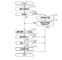
- FIG. 4 is a flowchart showing the processing procedure of the PCS in the first embodiment
- FIG. 5 is a diagram showing the relationship between the height of the three-dimensional compartment and the delay time
- FIG. 6 is a flowchart showing the processing procedure of the PCS in another example of the first embodiment
- FIG. 7 is a diagram showing a state in which a dividing line exists between the host vehicle and the pedestrian
- FIG. 8 is a flowchart showing the processing procedure of the PCS in the second embodiment.
- FIG. 1 shows a pre-crash safety system (hereinafter referred to as PCSS: Pre-crash safety system) to which a vehicle control device is applied.
- PCSS is an example of a vehicle system mounted on a vehicle, detects an object existing around the host vehicle, and when the detected object may collide with the host vehicle, the host vehicle collides with the object. Implement the avoidance operation of or the collision mitigation operation.
- a vehicle 50 shown in FIG. 1 includes a radar device 21 and an imaging device 22 as object detection sensors, a navigation device 23, an ECU 10, and an alarm device 31 and a brake device 32 as safety devices.
- the ECU 10 functions as a vehicle control device.
- the radar device 21 is attached at the front of the vehicle 50 so that the optical axis thereof is directed to the front of the vehicle, transmits a directional electromagnetic wave such as a millimeter wave or a laser as a transmission wave to the front of the vehicle.
- the relative position of the object in front of the vehicle is acquired at a predetermined cycle based on the reflected wave corresponding to the wave.
- the relative position is acquired as a position on the relative coordinates with the vehicle width direction of the vehicle 50 as the X axis and the traveling direction of the vehicle 50 as the Y axis when the vehicle 50 is the origin.
- the component in the vehicle width direction (X axis) corresponds to the lateral position of the object relative to the host vehicle 50
- the component in the traveling direction (Y axis) of the host vehicle 50 corresponds to the relative distance of the object.
- the relative position acquired in a predetermined cycle is output to the ECU 10.
- the imaging device 22 is an on-vehicle camera, and is configured using, for example, a CCD camera, a CMOS image sensor, a near infrared camera, or the like.
- the imaging device 22 is attached at a predetermined height (for example, near the upper end of the windshield) at the center in the vehicle width direction of the host vehicle 50, and captures an area extending in a predetermined angle range from the overhead viewpoint.
- the captured image that has been captured is output to the ECU 10 at predetermined intervals.
- the imaging device 22 may be a single-eye camera or a stereo camera.
- the navigation device 23 provides the ECU 10 with road information of the road on which the vehicle 50 travels.
- the navigation device 23 includes a memory for recording map information, and a position specifying unit for specifying the position of the vehicle 50 on the map by using positioning information transmitted from GPS (Global Positioning System) satellites. There is. Then, the navigation device 23 refers to the road information around the vehicle position based on the vehicle position on the identified map. And the road information referred to is transmitted to ECU10.
- the road information includes information indicating three-dimensional compartments that divide lanes.
- the three-dimensional compartments are provided as compartments between adjacent lanes or as compartments between lanes and sidewalks, and are, for example, guardrails, center poles, median dividers, curbs, fences and the like.
- the alarm device 31 warns the driver that an object is present in front of the vehicle according to a control command from the ECU 10.
- the alarm device 31 includes, for example, a speaker provided in a vehicle compartment and a display unit for displaying an image.
- the brake device 32 is a braking device that brakes the host vehicle 50.
- the brake device 32 operates when the possibility of collision with a front object increases. Specifically, the braking force for the brake operation by the driver is made stronger (brake assist function), or the automatic braking is performed if the driver does not perform the brake operation (automatic brake function).
- the ECU 10 is configured as a well-known microcomputer including a CPU and various memories (ROM, RAM), and executes control in the host vehicle 50 with reference to calculation programs and control data in the ROM.
- the ECU 10 operates the alarm device 31 and the brake device 32 based on the detection results output from the radar device 21 and the imaging device 22.
- the ECU 10 acquires the relative position (including the lateral position and the relative distance) of the object based on the object information output from the radar device 21 and the captured image output from the imaging device 22.
- the ECU 10 fuses these to obtain a fusion position as the relative position of the object.
- the time-series transition of the relative position of the object is stored as a history in a memory or the like.
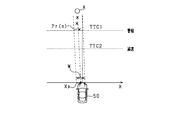
- the ECU 10 calculates a movement trajectory based on the acquired relative position of the object.
- the position Pr at each time of the object A and the movement trajectory calculated by the position Pr are shown.
- the position Pr (n) at time n is the position of the latest object A recorded in the history.
- the ECU 10 calculates a straight line passing a position closest to each position Pr as a movement trajectory by using a known linear interpolation operation such as the least square method.
- the ECU 10 calculates the collision lateral position Xp based on the calculated movement locus.
- the collision lateral position Xp is the position of the object in the vehicle width direction (X-axis direction) on the assumption that the distance from the object A to the host vehicle 50 in the Y-axis direction is zero.
- the position at which the distance from the object A to the host vehicle 50 in the Y-axis direction is zero corresponds to the X-axis, so the collision lateral position Xp is calculated as the intersection of the movement trajectory and the X-axis.
- the ECU 10 determines the possibility of collision between the host vehicle 50 and the object A based on the calculated collision lateral position Xp.
- the possibility of the host vehicle 50 colliding with the object A It is determined that there is
- the ECU 10 operates the safety devices 31 and 32 for the object A determined to have a possibility of collision based on a predetermined operation condition. Specifically, it calculates an allowance time (TTC) until the own vehicle 50 and the object A collide with each other, and operates the safety device according to the TTC.
- TTC allowance time
- the vertical axis represents TTC
- the horizontal axis represents the horizontal position.
- the TTC increases as the distance in the vertical axis direction from the host vehicle 50 to the object A increases, and the TTC decreases as the distance in the vertical axis direction from the host vehicle 50 to the object A decreases. .
- the ECU 10 when the calculated TTC becomes equal to or less than the operation timing TTC1 of the alarm device 31, the ECU 10 warns the driver that the object A is present in the forward direction.
- the calculated TTC becomes equal to or less than the actuation timing TTC2 of the brake device 32, an automatic brake is performed to reduce the speed of the host vehicle 50 by a predetermined amount.
- the own lane may be divided by three-dimensional division bodies, such as a guardrail.
- three-dimensional division bodies such as a guardrail.
- the operation of the safety device is controlled based on the relative position of the object with respect to the host vehicle 50, and the presence of a three-dimensional compartment such as a guardrail is not considered.
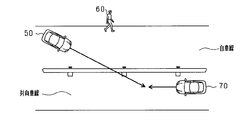
- FIG. 3 shows a situation where the host vehicle 50 travels in the host lane and the oncoming vehicle 70 travels in the opposite lane adjacent to the host lane, and a guardrail is provided between the host lane and the opposite lane. ing.
- the route of the host vehicle 50 temporarily goes to the opposite lane side.
- the path of the host vehicle 50 intersects with the movement trajectory of the oncoming vehicle 70, which may cause the safety devices 31 and 32 to be activated with respect to the oncoming vehicle 70 on the other side of the guardrail. In this case, there is a possibility that the operation becomes unnecessary.
- the ECU 10 recognizes a three-dimensional divided body of the own lane in which the own vehicle 50 travels, and determines that an object is present in the forward direction of the own lane. Then, when the presence of the object is determined, the operation mode of the alarm device 31 and the brake device 32 is changed based on the recognition that there is a three-dimensional compartment between the object and the vehicle 50. I did it. That is, by adding the position of the three-dimensional compartment to the relative position of the object, the operation of the safety device more suitable for the possibility of collision with the object is realized.
- the ECU 10 recognizes a three-dimensional divided body of the own lane in which the own vehicle 50 travels. Specifically, the presence of three-dimensional compartments is determined based on the map information stored in the navigation device 23. In this case, it is determined from the road information at the current location of the own vehicle 50 whether or not there is a three-dimensional compartment that divides the own lane.
- the presence of the three-dimensional divided body may be determined by using the object detection by the radar device 21 or the object detection by the imaging device 22. For example, in the object detection by the imaging device 22, the presence of the three-dimensional divided body is determined by collating the image data with dictionary information such as a guard rail and a median separator stored in advance.
- the ECU 10 determines that an object is present in the forward direction of travel of the host vehicle 50. Specifically, it is determined that an oncoming vehicle is present.
- the oncoming vehicle is determined based on a known method, for example, based on the ground speed.
- the ECU 10 calculates the ground speed of the object from the relative speed of the object acquired by the radar device 21 and the speed of the host vehicle 50, and the object is an oncoming vehicle when the calculated ground speed is a negative value. It is determined that In this case, the ground speed in the traveling direction of the host vehicle 50 is positive.
- the ECU 10 makes the operating conditions of the safety devices 31 and 32 strict if it is recognized that there is a three-dimensional divided body between the oncoming vehicle and the host vehicle 50. Change to the side. For example, the operation timing TTC1 of the alarm device 31 is changed to a smaller side, and the operation timing TTC2 of the brake device 32 is changed to a larger side. That is, the operation mode is changed to the side where the safety device becomes difficult to operate.
- the operation condition is not strictly changed. That is, in this case, the ECU 10 operates the safety devices 31 and 32 based on the normal operating conditions.
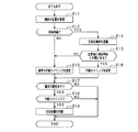
- step S11 the position of the object is acquired based on the detection results of the object detection sensors 21 and 22.
- a fusion position in which the radar position and the image position are fused is acquired as the position of the object.
- step S12 it is determined whether the object is an oncoming vehicle traveling in the oncoming traffic lane. Specifically, when the ground speed of the object is a negative value, it is determined that the object is an oncoming vehicle. If step S12 is NO, that is, if it is determined that the object is not an oncoming vehicle, the process proceeds to step S13. On the other hand, if step S12 is YES, that is, if it is determined that the object is an oncoming vehicle, the process proceeds to step S14.
- a three-dimensional compartment is recognized based on map information. For example, a guard rail or a center pole is recognized as a three-dimensional compartment.
- step S15 a normal operation timing is set as the operation timing of the safety devices 31 and 32.
- TTC1 is set as the normal operation timing of the alarm device 31
- TTC2 is set as the normal operation timing of the brake device 32.
- step S15 is YES, that is, if it is determined that there is a three-dimensional divided body between the host vehicle 50 and the oncoming vehicle, the process proceeds to step S16.
- step S16 the operation timings of the safety devices 31 and 32 are changed to be delayed. For example, assuming that the normal operation timing of the alarm device 31 is TTC1 and the normal operation timing of the brake device 32 is TTC2, the values are changed to smaller values. That is, it changes to the side which makes the safety devices 31 and 32 difficult to operate.
- step S17 it is determined whether there is a collision possibility between the vehicle 50 and an object. Specifically, it is determined whether the collision lateral position Xp obtained from the movement trajectory of the object belongs to a predetermined range. When step S17 is YES, it progresses to step S18. In step S18, it is determined whether or not it is time to operate each safety device with respect to an object having a possibility of collision. When it is determined that it is the operation timing (step S18: YES), the corresponding safety device is operated (step S19). On the other hand, when step S17 and step S18 are NO, the safety device is not operated, and the present process ends.
- steps S11 and S12 correspond to a "determination unit”
- step S14 corresponds to a "recognition unit”
- step S16 corresponds to a "change unit”.
- the operation mode of the safety devices 31 and 32 is changed based on the recognition that there is a division between the object and the vehicle 50. Specifically, if it is recognized that there is a section between the object and the vehicle 50, the operation timing of the safety devices 31 and 32 is changed to the side to be delayed. As a result, the safety devices 31 and 32 are less likely to be actuated, and unnecessary actuation of an object beyond the partition can be suppressed.
- the operation timings of the safety devices 31 and 32 are not changed, so the safety device 31 can be quickly provided to such an object. , 32 can be operated. Thereby, the safety devices 31 and 32 can be properly operated on the object.
- the possibility of a collision is considered to be low even if the moving directions of the host vehicle 50 and the oncoming vehicle intersect.
- the partition is a three-dimensional partition, the possibility of collision is considered to be further reduced.
- the operation timing of the safety devices 31 and 32 is changed to the later side, so that collision with the object is possible.
- the safety devices 31, 32 can be operated with more consideration given to the nature.
- the operation timings of the alarm device 31 and the brake device 32 are changed to the late side, but either one may be changed to the late side. In this case, for example, only the operation timing of the alarm device 31 may be changed to a later side. According to this configuration, the operation of the brake device 32 is secured while reducing the complexity of the driver accompanying the operation of the alarm device 31.
- the height from the road of the three-dimensional compartment may be acquired, and the operation timing of the safety devices 31 and 32 may be changed to be delayed based on the height of the three-dimensional compartment.
- step S12 when it is determined that an oncoming vehicle is present by object detection (step S12: YES), the process proceeds to step S14.
- step S14 while recognizing a three-dimensional compartment, the height of the three-dimensional compartment is acquired.
- the height of the three-dimensional compartment is acquired based on, for example, the position of the three-dimensional compartment and the map information in which the height of the three-dimensional compartment is stored in advance. In addition, it may be acquired based on the input of the radar device 21 or the imaging device 22.
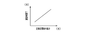
- step S16 the operation timing is changed based on the height of the three-dimensional compartments. For example, as shown in FIG. 5, it is changed based on the correlation map between the height of the three-dimensional compartment and the delay time T.
- the delay time T means the time to delay the actuation timing from the normal actuation timing. That is, when the delay time T is zero, the normal operation timing is set. In FIG. 5, the delay time T is set to be larger as the height of the three-dimensional compartments becomes higher.
- the operation timing is set to be later than that when lower (for example, in the case of curb). That is, the safety devices 31 and 32 are set so as not to be operated easily.
- the safety device 31 or 32 is changed to the side that delays the operation timing based on the height of the three-dimensional compartment to further consider the possibility of a collision with an oncoming vehicle. , 32 can be operated.
- the operation timing of the safety device is changed as the change of the operation mode of the safety devices 31 and 32.
- the present invention is not limited to this.
- the operating mode may be changed so as not to operate the safety device.
- step S16 is omitted.
- step S12 when it is determined that an oncoming vehicle is present by object detection (step S12: YES), and it is determined that a three-dimensional partitioned body is present between the host vehicle 50 and the oncoming vehicle (step S15: YES).
- the present processing ends without performing the determination of the collision possibility. That is, when it is determined that there is a three-dimensional divided body between the host vehicle 50 and the oncoming vehicle, it is considered that there is no possibility of a collision, and the safety devices 31 and 32 are not operated.
- the safety devices 31 and 32 are not activated. Therefore, unnecessary operation of the safety devices 31 and 32 can be suitably suppressed.
- the height of the three-dimensional compartments may be further taken into consideration.
- the ECU 10 has a three-dimensional divided body between the host vehicle 50 and the oncoming vehicle, and the height of the three-dimensional divided body is a predetermined height Hth It is determined whether it is higher than (for example, 1 m). If step 15 is YES, this processing ends as it is without carrying out the determination of the collision possibility. On the other hand, if step 15 is NO, it will progress to step S13 and will set a normal action timing.
- the operation timing of the safety device when the three-dimensional compartment between the host vehicle 50 and the oncoming vehicle is recognized, the operation timing of the safety device is changed, but it may be other than the oncoming vehicle, for example, the host vehicle 50 and walking.
- the operation timing of the safety device may be changed.
- the presence of a pedestrian is determined by collating image data based on a captured image with the pedestrian's dictionary information stored in advance.
- the type of object may be determined, and the operation timing may be changed according to the type of the determined object.
- the operation timing of the alarm device 31 when the object is a pedestrian, the operation timing is changed from TTC1 to TTC1A, and when the object is an oncoming vehicle, it is changed from TTC1 to TTC1B.
- the operation timing after the change may be set based on the collision possibility for each object in consideration of the three-dimensional compartments. In the above case, for example, TTC1A> TTC1B is set.
- FIG. 7 shows a situation in which the vehicle 50 travels in the own lane divided by the dividing lines L11 and L12, and the pedestrian 80 moves outside the own lane.
- the safety devices 31 and 32 may be activated for the pedestrian 80.
- the ECU 10 recognizes the dividing line, and determines whether a dividing line exists between the vehicle 50 and the object. And, when the dividing line is present, the operation mode of the safety device is changed. Specifically, the operation timing of the safety device is changed to the later side.
- a well-known method is used for recognition of a partition line. For example, a sobel filter or the like is applied to the photographed image to extract edge points, and a well-known approximation method or the like is applied to the extracted edge points to recognize the dividing lines.
- the demarcation line recognized on the left side of the own vehicle 50 and closest to the own vehicle 50 is recognized as the demarcation line on the left side of the own lane, and on the right side of the own vehicle 50 and the own vehicle 50 Recognize the demarcation line recognized closest to as the demarcation line on the right side of the own lane.
- recognition of a division line is not restricted to the method by image recognition.
- the ECU 10 may recognize the dividing line based on the map information and the vehicle position.
- the map information in the navigation device 23 includes the position of the dividing line of each road, and the dividing line is recognized from the vehicle position on the map.
- the PCS implemented in the second embodiment will be described with reference to the flowchart of FIG.
- the present process is repeatedly performed by the ECU 10 at a predetermined cycle in place of FIG. 4 described above.
- FIG. 8 the same processes as in FIG. 4 will be assigned the same step numbers to simplify the description.
- step S21 it is determined whether the object is a pedestrian.
- the determination is made based on the pedestrian's dictionary information from the captured image.
- step S21 is NO, that is, when it is determined that the object is not a pedestrian, the process proceeds to step S13.
- step S21 is YES, that is, if it is determined that the object is a pedestrian, the process proceeds to step S22.
- step S22 the lane line of the own lane is recognized based on the captured image.
- step S23 it is determined whether or not there is a dividing line between the host vehicle 50 and the pedestrian. Specifically, the determination is made based on the relative positional relationship between the recognized dividing line, the vehicle 50, and the pedestrian. For example, when a dividing line exists in the movement trajectory of the pedestrian with respect to the path of the own vehicle 50, it is determined that the dividing line exists between the own vehicle 50 and the pedestrian.
- step S23 If it is determined that step S23 is NO, that is, if it is determined that there is no dividing line between the host vehicle 50 and the pedestrian, the process proceeds to step S13. In step S13, a normal operation timing is set as the operation timing of the safety devices 31 and 32. On the other hand, if step S23 is YES, that is, if it is determined that there is a dividing line between the vehicle 50 and the pedestrian, the process proceeds to step S16. In step S16, the operation timings of the safety devices 31 and 32 are changed to be delayed. The subsequent processing is as described above.
- the possibility of a collision is low even if the pedestrian and the host vehicle 50 are in a close proximity state. Conceivable.
- the operation timing of the safety devices 31 and 32 is changed to a later side. As a result, the safety devices 31 and 32 are less likely to be actuated, and unnecessary actuation of pedestrians behind the lane markings can be suppressed.
- the operation timing is not changed, so the safety devices 31 and 32 are operated quickly for such a pedestrian. It can be done.
- the operation timing of the safety device is changed, but it may be other than the pedestrian, for example, the host vehicle 50 and the oncoming vehicle When it recognizes the division line between and, it is good also as composition which changes operation timing of a safety device.
- the oncoming vehicle or the pedestrian is detected as the object.
- the invention is not limited to this.
- a two-wheeled vehicle such as a bicycle or a motorcycle may be detected.
Landscapes
- Engineering & Computer Science (AREA)
- Radar, Positioning & Navigation (AREA)
- Remote Sensing (AREA)
- Mechanical Engineering (AREA)
- Physics & Mathematics (AREA)
- General Physics & Mathematics (AREA)
- Transportation (AREA)
- Automation & Control Theory (AREA)
- Traffic Control Systems (AREA)
- Navigation (AREA)
- Regulating Braking Force (AREA)
Applications Claiming Priority (2)
| Application Number | Priority Date | Filing Date | Title |
|---|---|---|---|
| JP2017127328A JP6733616B2 (ja) | 2017-06-29 | 2017-06-29 | 車両制御装置 |
| JP2017-127328 | 2017-06-29 |
Publications (1)
| Publication Number | Publication Date |
|---|---|
| WO2019003923A1 true WO2019003923A1 (ja) | 2019-01-03 |
Family
ID=64740631
Family Applications (1)
| Application Number | Title | Priority Date | Filing Date |
|---|---|---|---|
| PCT/JP2018/022592 Ceased WO2019003923A1 (ja) | 2017-06-29 | 2018-06-13 | 車両制御装置 |
Country Status (2)
| Country | Link |
|---|---|
| JP (1) | JP6733616B2 (enExample) |
| WO (1) | WO2019003923A1 (enExample) |
Families Citing this family (2)
| Publication number | Priority date | Publication date | Assignee | Title |
|---|---|---|---|---|
| JP7192600B2 (ja) * | 2019-03-20 | 2022-12-20 | 株式会社デンソー | 警報装置 |
| JP7275000B2 (ja) * | 2019-10-11 | 2023-05-17 | 株式会社デンソー | 制御装置 |
Citations (2)
| Publication number | Priority date | Publication date | Assignee | Title |
|---|---|---|---|---|
| JP2016021210A (ja) * | 2014-07-16 | 2016-02-04 | クラリオン株式会社 | 車載器、サーバー装置および注意喚起システム |
| WO2017010333A1 (ja) * | 2015-07-10 | 2017-01-19 | 田山 修一 | 車輌用画像表示システム及び方法 |
-
2017
- 2017-06-29 JP JP2017127328A patent/JP6733616B2/ja active Active
-
2018
- 2018-06-13 WO PCT/JP2018/022592 patent/WO2019003923A1/ja not_active Ceased
Patent Citations (2)
| Publication number | Priority date | Publication date | Assignee | Title |
|---|---|---|---|---|
| JP2016021210A (ja) * | 2014-07-16 | 2016-02-04 | クラリオン株式会社 | 車載器、サーバー装置および注意喚起システム |
| WO2017010333A1 (ja) * | 2015-07-10 | 2017-01-19 | 田山 修一 | 車輌用画像表示システム及び方法 |
Also Published As
| Publication number | Publication date |
|---|---|
| JP2019012322A (ja) | 2019-01-24 |
| JP6733616B2 (ja) | 2020-08-05 |
Similar Documents
| Publication | Publication Date | Title |
|---|---|---|
| JP5345350B2 (ja) | 車両の運転支援装置 | |
| CN108541325B (zh) | 驾驶辅助装置以及驾驶辅助方法 | |
| CN109204311B (zh) | 一种汽车速度控制方法和装置 | |
| JP7059786B2 (ja) | 車外報知装置 | |
| JP7085371B2 (ja) | 車両制御装置、車両制御方法、およびプログラム | |
| US10747219B2 (en) | Processing apparatus, vehicle, processing method, and storage medium | |
| WO2016159288A1 (ja) | 物標存在判定方法及び装置 | |
| WO2019058446A1 (ja) | 車両制御装置、車両制御方法、及びプログラム | |
| JP2016192166A (ja) | 車両制御装置、及び車両制御方法 | |
| WO2019073511A1 (ja) | 車両制御装置、車両制御方法、及びプログラム | |
| JP7275623B2 (ja) | 運転支援装置 | |
| WO2018074287A1 (ja) | 車両制御装置 | |
| CN112447057A (zh) | 停止线位置推定装置及车辆控制系统 | |
| JP7324600B2 (ja) | 車両制御装置、車両制御方法、およびプログラム | |
| JP2016192164A (ja) | 物体検知装置、及び物体検知方法 | |
| JP2017068461A (ja) | 車両の運転支援装置 | |
| JP7239353B2 (ja) | 車両における制動支援制御装置、制動支援制御システムおよび制動支援制御方法 | |
| JP7159267B2 (ja) | 車両制御装置、車両制御方法、およびプログラム | |
| JP2019046143A (ja) | 走行支援装置 | |
| WO2019009032A1 (ja) | 車両制御装置 | |
| JP5210064B2 (ja) | 車両の衝突防止装置 | |
| JP5452004B2 (ja) | 車両の運転支援装置 | |
| JP6583697B2 (ja) | 周辺監視装置、制御装置、周辺監視方法、およびプログラム | |
| JP6733616B2 (ja) | 車両制御装置 | |
| CN114179789A (zh) | 车辆控制装置、车辆控制方法及存储介质 |
Legal Events
| Date | Code | Title | Description |
|---|---|---|---|
| 121 | Ep: the epo has been informed by wipo that ep was designated in this application |
Ref document number: 18823552 Country of ref document: EP Kind code of ref document: A1 |
|
| NENP | Non-entry into the national phase |
Ref country code: DE |
|
| 122 | Ep: pct application non-entry in european phase |
Ref document number: 18823552 Country of ref document: EP Kind code of ref document: A1 |