WO2019003923A1 - 車両制御装置 - Google Patents
車両制御装置 Download PDFInfo
- Publication number
- WO2019003923A1 WO2019003923A1 PCT/JP2018/022592 JP2018022592W WO2019003923A1 WO 2019003923 A1 WO2019003923 A1 WO 2019003923A1 JP 2018022592 W JP2018022592 W JP 2018022592W WO 2019003923 A1 WO2019003923 A1 WO 2019003923A1
- Authority
- WO
- WIPO (PCT)
- Prior art keywords
- vehicle
- host vehicle
- present
- lane
- control device
- Prior art date
Links
Images


Classifications
-
- B—PERFORMING OPERATIONS; TRANSPORTING
- B60—VEHICLES IN GENERAL
- B60R—VEHICLES, VEHICLE FITTINGS, OR VEHICLE PARTS, NOT OTHERWISE PROVIDED FOR
- B60R21/00—Arrangements or fittings on vehicles for protecting or preventing injuries to occupants or pedestrians in case of accidents or other traffic risks
-
- B—PERFORMING OPERATIONS; TRANSPORTING
- B60—VEHICLES IN GENERAL
- B60T—VEHICLE BRAKE CONTROL SYSTEMS OR PARTS THEREOF; BRAKE CONTROL SYSTEMS OR PARTS THEREOF, IN GENERAL; ARRANGEMENT OF BRAKING ELEMENTS ON VEHICLES IN GENERAL; PORTABLE DEVICES FOR PREVENTING UNWANTED MOVEMENT OF VEHICLES; VEHICLE MODIFICATIONS TO FACILITATE COOLING OF BRAKES
- B60T7/00—Brake-action initiating means
- B60T7/12—Brake-action initiating means for automatic initiation; for initiation not subject to will of driver or passenger
-
- G—PHYSICS
- G01—MEASURING; TESTING
- G01C—MEASURING DISTANCES, LEVELS OR BEARINGS; SURVEYING; NAVIGATION; GYROSCOPIC INSTRUMENTS; PHOTOGRAMMETRY OR VIDEOGRAMMETRY
- G01C21/00—Navigation; Navigational instruments not provided for in groups G01C1/00 - G01C19/00
- G01C21/26—Navigation; Navigational instruments not provided for in groups G01C1/00 - G01C19/00 specially adapted for navigation in a road network
-
- G—PHYSICS
- G08—SIGNALLING
- G08G—TRAFFIC CONTROL SYSTEMS
- G08G1/00—Traffic control systems for road vehicles
- G08G1/16—Anti-collision systems
Definitions
- the present disclosure relates to a vehicle control device that activates a safety device on an object.
- the vehicle control device of Patent Document 1 estimates the movement trajectory of the object relative to the path of the host vehicle based on the history of the position of the object, and controls the operation of the safety device based on the estimated movement trajectory. .
- the safety device in the operation control of the safety device by the vehicle control device, the presence of a guard rail or the like that divides the own lane is not considered. Therefore, for example, even in a situation where a guardrail exists between the host vehicle and the object and the possibility of a collision between the host vehicle and the object is low, the safety device can prevent the object located behind the guardrail. It is believed that it may be activated. In such a case, the safety device may be unnecessarily operated.
- This indication is made in view of the above-mentioned subject, and the main purpose is to provide a vehicle control device which can operate a safety device appropriately to an object.
- a vehicle control device that is applied to a vehicle including an object detection sensor that detects an object around the host vehicle, and operates a safety device that avoids or reduces a collision with the object based on the detection result of the object detection sensor.
- a recognition unit that recognizes a section of the own lane in which the own vehicle travels;
- a determination unit that determines that an object detected by the object detection sensor is present in front of the traveling direction of the host vehicle; The change of the operation mode of the safety device based on the recognition that the division portion is present between the object and the host vehicle when the presence of the object is determined by the determination unit.
- Department Equipped with
- Vehicle control is known in which an object detection sensor detects an object in the vicinity of the host vehicle and the safety device is operated based on the detection result.
- control does not take into consideration the presence of a compartment such as a guardrail that divides the own lane, and for example, even in a situation where a guardrail exists between an object and the subject vehicle, the back side of the guardrail
- the safety device may be activated for the object of
- the section of the own lane in which the own vehicle travels is recognized, and it is determined that the object detected by the object detection sensor is present in the forward direction of the own vehicle. Then, when the presence of the object is determined, the operation mode of the safety device is changed based on the recognition that there is a division between the object and the vehicle.
- the possibility of a collision is considered to be low even if the object and the host vehicle are in a close proximity state.
- the operation mode of the safety device is changed based on the recognition that there is a partition between the object and the vehicle, for example, it is changed to the side that makes it difficult to operate the safety device. By doing this, unnecessary operation of the safety device can be avoided. This enables the safety device to operate properly on the object.
- FIG. 1 is a block diagram showing a schematic configuration of a vehicle control device
- FIG. 2 is a diagram for explaining collision avoidance control based on a movement trajectory of an object
- FIG. 3 is a view showing a situation where a guardrail exists between the host vehicle and the oncoming vehicle
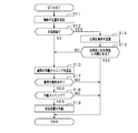
- FIG. 4 is a flowchart showing the processing procedure of the PCS in the first embodiment
- FIG. 5 is a diagram showing the relationship between the height of the three-dimensional compartment and the delay time
- FIG. 6 is a flowchart showing the processing procedure of the PCS in another example of the first embodiment
- FIG. 7 is a diagram showing a state in which a dividing line exists between the host vehicle and the pedestrian
- FIG. 8 is a flowchart showing the processing procedure of the PCS in the second embodiment.
- FIG. 1 shows a pre-crash safety system (hereinafter referred to as PCSS: Pre-crash safety system) to which a vehicle control device is applied.
- PCSS is an example of a vehicle system mounted on a vehicle, detects an object existing around the host vehicle, and when the detected object may collide with the host vehicle, the host vehicle collides with the object. Implement the avoidance operation of or the collision mitigation operation.
- a vehicle 50 shown in FIG. 1 includes a radar device 21 and an imaging device 22 as object detection sensors, a navigation device 23, an ECU 10, and an alarm device 31 and a brake device 32 as safety devices.
- the ECU 10 functions as a vehicle control device.
- the radar device 21 is attached at the front of the vehicle 50 so that the optical axis thereof is directed to the front of the vehicle, transmits a directional electromagnetic wave such as a millimeter wave or a laser as a transmission wave to the front of the vehicle.
- the relative position of the object in front of the vehicle is acquired at a predetermined cycle based on the reflected wave corresponding to the wave.
- the relative position is acquired as a position on the relative coordinates with the vehicle width direction of the vehicle 50 as the X axis and the traveling direction of the vehicle 50 as the Y axis when the vehicle 50 is the origin.
- the component in the vehicle width direction (X axis) corresponds to the lateral position of the object relative to the host vehicle 50
- the component in the traveling direction (Y axis) of the host vehicle 50 corresponds to the relative distance of the object.
- the relative position acquired in a predetermined cycle is output to the ECU 10.
- the imaging device 22 is an on-vehicle camera, and is configured using, for example, a CCD camera, a CMOS image sensor, a near infrared camera, or the like.
- the imaging device 22 is attached at a predetermined height (for example, near the upper end of the windshield) at the center in the vehicle width direction of the host vehicle 50, and captures an area extending in a predetermined angle range from the overhead viewpoint.
- the captured image that has been captured is output to the ECU 10 at predetermined intervals.
- the imaging device 22 may be a single-eye camera or a stereo camera.
- the navigation device 23 provides the ECU 10 with road information of the road on which the vehicle 50 travels.
- the navigation device 23 includes a memory for recording map information, and a position specifying unit for specifying the position of the vehicle 50 on the map by using positioning information transmitted from GPS (Global Positioning System) satellites. There is. Then, the navigation device 23 refers to the road information around the vehicle position based on the vehicle position on the identified map. And the road information referred to is transmitted to ECU10.
- the road information includes information indicating three-dimensional compartments that divide lanes.
- the three-dimensional compartments are provided as compartments between adjacent lanes or as compartments between lanes and sidewalks, and are, for example, guardrails, center poles, median dividers, curbs, fences and the like.
- the alarm device 31 warns the driver that an object is present in front of the vehicle according to a control command from the ECU 10.
- the alarm device 31 includes, for example, a speaker provided in a vehicle compartment and a display unit for displaying an image.
- the brake device 32 is a braking device that brakes the host vehicle 50.
- the brake device 32 operates when the possibility of collision with a front object increases. Specifically, the braking force for the brake operation by the driver is made stronger (brake assist function), or the automatic braking is performed if the driver does not perform the brake operation (automatic brake function).
- the ECU 10 is configured as a well-known microcomputer including a CPU and various memories (ROM, RAM), and executes control in the host vehicle 50 with reference to calculation programs and control data in the ROM.
- the ECU 10 operates the alarm device 31 and the brake device 32 based on the detection results output from the radar device 21 and the imaging device 22.
- the ECU 10 acquires the relative position (including the lateral position and the relative distance) of the object based on the object information output from the radar device 21 and the captured image output from the imaging device 22.
- the ECU 10 fuses these to obtain a fusion position as the relative position of the object.
- the time-series transition of the relative position of the object is stored as a history in a memory or the like.
- the ECU 10 calculates a movement trajectory based on the acquired relative position of the object.
- the position Pr at each time of the object A and the movement trajectory calculated by the position Pr are shown.
- the position Pr (n) at time n is the position of the latest object A recorded in the history.
- the ECU 10 calculates a straight line passing a position closest to each position Pr as a movement trajectory by using a known linear interpolation operation such as the least square method.
- the ECU 10 calculates the collision lateral position Xp based on the calculated movement locus.
- the collision lateral position Xp is the position of the object in the vehicle width direction (X-axis direction) on the assumption that the distance from the object A to the host vehicle 50 in the Y-axis direction is zero.
- the position at which the distance from the object A to the host vehicle 50 in the Y-axis direction is zero corresponds to the X-axis, so the collision lateral position Xp is calculated as the intersection of the movement trajectory and the X-axis.
- the ECU 10 determines the possibility of collision between the host vehicle 50 and the object A based on the calculated collision lateral position Xp.
- the possibility of the host vehicle 50 colliding with the object A It is determined that there is
- the ECU 10 operates the safety devices 31 and 32 for the object A determined to have a possibility of collision based on a predetermined operation condition. Specifically, it calculates an allowance time (TTC) until the own vehicle 50 and the object A collide with each other, and operates the safety device according to the TTC.
- TTC allowance time
- the vertical axis represents TTC
- the horizontal axis represents the horizontal position.
- the TTC increases as the distance in the vertical axis direction from the host vehicle 50 to the object A increases, and the TTC decreases as the distance in the vertical axis direction from the host vehicle 50 to the object A decreases. .
- the ECU 10 when the calculated TTC becomes equal to or less than the operation timing TTC1 of the alarm device 31, the ECU 10 warns the driver that the object A is present in the forward direction.
- the calculated TTC becomes equal to or less than the actuation timing TTC2 of the brake device 32, an automatic brake is performed to reduce the speed of the host vehicle 50 by a predetermined amount.
- the own lane may be divided by three-dimensional division bodies, such as a guardrail.
- three-dimensional division bodies such as a guardrail.
- the operation of the safety device is controlled based on the relative position of the object with respect to the host vehicle 50, and the presence of a three-dimensional compartment such as a guardrail is not considered.
- FIG. 3 shows a situation where the host vehicle 50 travels in the host lane and the oncoming vehicle 70 travels in the opposite lane adjacent to the host lane, and a guardrail is provided between the host lane and the opposite lane. ing.
- the route of the host vehicle 50 temporarily goes to the opposite lane side.
- the path of the host vehicle 50 intersects with the movement trajectory of the oncoming vehicle 70, which may cause the safety devices 31 and 32 to be activated with respect to the oncoming vehicle 70 on the other side of the guardrail. In this case, there is a possibility that the operation becomes unnecessary.
- the ECU 10 recognizes a three-dimensional divided body of the own lane in which the own vehicle 50 travels, and determines that an object is present in the forward direction of the own lane. Then, when the presence of the object is determined, the operation mode of the alarm device 31 and the brake device 32 is changed based on the recognition that there is a three-dimensional compartment between the object and the vehicle 50. I did it. That is, by adding the position of the three-dimensional compartment to the relative position of the object, the operation of the safety device more suitable for the possibility of collision with the object is realized.
- the ECU 10 recognizes a three-dimensional divided body of the own lane in which the own vehicle 50 travels. Specifically, the presence of three-dimensional compartments is determined based on the map information stored in the navigation device 23. In this case, it is determined from the road information at the current location of the own vehicle 50 whether or not there is a three-dimensional compartment that divides the own lane.
- the presence of the three-dimensional divided body may be determined by using the object detection by the radar device 21 or the object detection by the imaging device 22. For example, in the object detection by the imaging device 22, the presence of the three-dimensional divided body is determined by collating the image data with dictionary information such as a guard rail and a median separator stored in advance.
- the ECU 10 determines that an object is present in the forward direction of travel of the host vehicle 50. Specifically, it is determined that an oncoming vehicle is present.
- the oncoming vehicle is determined based on a known method, for example, based on the ground speed.
- the ECU 10 calculates the ground speed of the object from the relative speed of the object acquired by the radar device 21 and the speed of the host vehicle 50, and the object is an oncoming vehicle when the calculated ground speed is a negative value. It is determined that In this case, the ground speed in the traveling direction of the host vehicle 50 is positive.
- the ECU 10 makes the operating conditions of the safety devices 31 and 32 strict if it is recognized that there is a three-dimensional divided body between the oncoming vehicle and the host vehicle 50. Change to the side. For example, the operation timing TTC1 of the alarm device 31 is changed to a smaller side, and the operation timing TTC2 of the brake device 32 is changed to a larger side. That is, the operation mode is changed to the side where the safety device becomes difficult to operate.
- the operation condition is not strictly changed. That is, in this case, the ECU 10 operates the safety devices 31 and 32 based on the normal operating conditions.
- step S11 the position of the object is acquired based on the detection results of the object detection sensors 21 and 22.
- a fusion position in which the radar position and the image position are fused is acquired as the position of the object.
- step S12 it is determined whether the object is an oncoming vehicle traveling in the oncoming traffic lane. Specifically, when the ground speed of the object is a negative value, it is determined that the object is an oncoming vehicle. If step S12 is NO, that is, if it is determined that the object is not an oncoming vehicle, the process proceeds to step S13. On the other hand, if step S12 is YES, that is, if it is determined that the object is an oncoming vehicle, the process proceeds to step S14.
- a three-dimensional compartment is recognized based on map information. For example, a guard rail or a center pole is recognized as a three-dimensional compartment.
- step S15 a normal operation timing is set as the operation timing of the safety devices 31 and 32.
- TTC1 is set as the normal operation timing of the alarm device 31
- TTC2 is set as the normal operation timing of the brake device 32.
- step S15 is YES, that is, if it is determined that there is a three-dimensional divided body between the host vehicle 50 and the oncoming vehicle, the process proceeds to step S16.
- step S16 the operation timings of the safety devices 31 and 32 are changed to be delayed. For example, assuming that the normal operation timing of the alarm device 31 is TTC1 and the normal operation timing of the brake device 32 is TTC2, the values are changed to smaller values. That is, it changes to the side which makes the safety devices 31 and 32 difficult to operate.
- step S17 it is determined whether there is a collision possibility between the vehicle 50 and an object. Specifically, it is determined whether the collision lateral position Xp obtained from the movement trajectory of the object belongs to a predetermined range. When step S17 is YES, it progresses to step S18. In step S18, it is determined whether or not it is time to operate each safety device with respect to an object having a possibility of collision. When it is determined that it is the operation timing (step S18: YES), the corresponding safety device is operated (step S19). On the other hand, when step S17 and step S18 are NO, the safety device is not operated, and the present process ends.
- steps S11 and S12 correspond to a "determination unit”
- step S14 corresponds to a "recognition unit”
- step S16 corresponds to a "change unit”.
- the operation mode of the safety devices 31 and 32 is changed based on the recognition that there is a division between the object and the vehicle 50. Specifically, if it is recognized that there is a section between the object and the vehicle 50, the operation timing of the safety devices 31 and 32 is changed to the side to be delayed. As a result, the safety devices 31 and 32 are less likely to be actuated, and unnecessary actuation of an object beyond the partition can be suppressed.
- the operation timings of the safety devices 31 and 32 are not changed, so the safety device 31 can be quickly provided to such an object. , 32 can be operated. Thereby, the safety devices 31 and 32 can be properly operated on the object.
- the possibility of a collision is considered to be low even if the moving directions of the host vehicle 50 and the oncoming vehicle intersect.
- the partition is a three-dimensional partition, the possibility of collision is considered to be further reduced.
- the operation timing of the safety devices 31 and 32 is changed to the later side, so that collision with the object is possible.
- the safety devices 31, 32 can be operated with more consideration given to the nature.
- the operation timings of the alarm device 31 and the brake device 32 are changed to the late side, but either one may be changed to the late side. In this case, for example, only the operation timing of the alarm device 31 may be changed to a later side. According to this configuration, the operation of the brake device 32 is secured while reducing the complexity of the driver accompanying the operation of the alarm device 31.
- the height from the road of the three-dimensional compartment may be acquired, and the operation timing of the safety devices 31 and 32 may be changed to be delayed based on the height of the three-dimensional compartment.
- step S12 when it is determined that an oncoming vehicle is present by object detection (step S12: YES), the process proceeds to step S14.
- step S14 while recognizing a three-dimensional compartment, the height of the three-dimensional compartment is acquired.
- the height of the three-dimensional compartment is acquired based on, for example, the position of the three-dimensional compartment and the map information in which the height of the three-dimensional compartment is stored in advance. In addition, it may be acquired based on the input of the radar device 21 or the imaging device 22.
- step S16 the operation timing is changed based on the height of the three-dimensional compartments. For example, as shown in FIG. 5, it is changed based on the correlation map between the height of the three-dimensional compartment and the delay time T.
- the delay time T means the time to delay the actuation timing from the normal actuation timing. That is, when the delay time T is zero, the normal operation timing is set. In FIG. 5, the delay time T is set to be larger as the height of the three-dimensional compartments becomes higher.
- the operation timing is set to be later than that when lower (for example, in the case of curb). That is, the safety devices 31 and 32 are set so as not to be operated easily.
- the safety device 31 or 32 is changed to the side that delays the operation timing based on the height of the three-dimensional compartment to further consider the possibility of a collision with an oncoming vehicle. , 32 can be operated.
- the operation timing of the safety device is changed as the change of the operation mode of the safety devices 31 and 32.
- the present invention is not limited to this.
- the operating mode may be changed so as not to operate the safety device.
- step S16 is omitted.
- step S12 when it is determined that an oncoming vehicle is present by object detection (step S12: YES), and it is determined that a three-dimensional partitioned body is present between the host vehicle 50 and the oncoming vehicle (step S15: YES).
- the present processing ends without performing the determination of the collision possibility. That is, when it is determined that there is a three-dimensional divided body between the host vehicle 50 and the oncoming vehicle, it is considered that there is no possibility of a collision, and the safety devices 31 and 32 are not operated.
- the safety devices 31 and 32 are not activated. Therefore, unnecessary operation of the safety devices 31 and 32 can be suitably suppressed.
- the height of the three-dimensional compartments may be further taken into consideration.
- the ECU 10 has a three-dimensional divided body between the host vehicle 50 and the oncoming vehicle, and the height of the three-dimensional divided body is a predetermined height Hth It is determined whether it is higher than (for example, 1 m). If step 15 is YES, this processing ends as it is without carrying out the determination of the collision possibility. On the other hand, if step 15 is NO, it will progress to step S13 and will set a normal action timing.
- the operation timing of the safety device when the three-dimensional compartment between the host vehicle 50 and the oncoming vehicle is recognized, the operation timing of the safety device is changed, but it may be other than the oncoming vehicle, for example, the host vehicle 50 and walking.
- the operation timing of the safety device may be changed.
- the presence of a pedestrian is determined by collating image data based on a captured image with the pedestrian's dictionary information stored in advance.
- the type of object may be determined, and the operation timing may be changed according to the type of the determined object.
- the operation timing of the alarm device 31 when the object is a pedestrian, the operation timing is changed from TTC1 to TTC1A, and when the object is an oncoming vehicle, it is changed from TTC1 to TTC1B.
- the operation timing after the change may be set based on the collision possibility for each object in consideration of the three-dimensional compartments. In the above case, for example, TTC1A> TTC1B is set.
- FIG. 7 shows a situation in which the vehicle 50 travels in the own lane divided by the dividing lines L11 and L12, and the pedestrian 80 moves outside the own lane.
- the safety devices 31 and 32 may be activated for the pedestrian 80.
- the ECU 10 recognizes the dividing line, and determines whether a dividing line exists between the vehicle 50 and the object. And, when the dividing line is present, the operation mode of the safety device is changed. Specifically, the operation timing of the safety device is changed to the later side.
- a well-known method is used for recognition of a partition line. For example, a sobel filter or the like is applied to the photographed image to extract edge points, and a well-known approximation method or the like is applied to the extracted edge points to recognize the dividing lines.
- the demarcation line recognized on the left side of the own vehicle 50 and closest to the own vehicle 50 is recognized as the demarcation line on the left side of the own lane, and on the right side of the own vehicle 50 and the own vehicle 50 Recognize the demarcation line recognized closest to as the demarcation line on the right side of the own lane.
- recognition of a division line is not restricted to the method by image recognition.
- the ECU 10 may recognize the dividing line based on the map information and the vehicle position.
- the map information in the navigation device 23 includes the position of the dividing line of each road, and the dividing line is recognized from the vehicle position on the map.
- the PCS implemented in the second embodiment will be described with reference to the flowchart of FIG.
- the present process is repeatedly performed by the ECU 10 at a predetermined cycle in place of FIG. 4 described above.
- FIG. 8 the same processes as in FIG. 4 will be assigned the same step numbers to simplify the description.
- step S21 it is determined whether the object is a pedestrian.
- the determination is made based on the pedestrian's dictionary information from the captured image.
- step S21 is NO, that is, when it is determined that the object is not a pedestrian, the process proceeds to step S13.
- step S21 is YES, that is, if it is determined that the object is a pedestrian, the process proceeds to step S22.
- step S22 the lane line of the own lane is recognized based on the captured image.
- step S23 it is determined whether or not there is a dividing line between the host vehicle 50 and the pedestrian. Specifically, the determination is made based on the relative positional relationship between the recognized dividing line, the vehicle 50, and the pedestrian. For example, when a dividing line exists in the movement trajectory of the pedestrian with respect to the path of the own vehicle 50, it is determined that the dividing line exists between the own vehicle 50 and the pedestrian.
- step S23 If it is determined that step S23 is NO, that is, if it is determined that there is no dividing line between the host vehicle 50 and the pedestrian, the process proceeds to step S13. In step S13, a normal operation timing is set as the operation timing of the safety devices 31 and 32. On the other hand, if step S23 is YES, that is, if it is determined that there is a dividing line between the vehicle 50 and the pedestrian, the process proceeds to step S16. In step S16, the operation timings of the safety devices 31 and 32 are changed to be delayed. The subsequent processing is as described above.
- the possibility of a collision is low even if the pedestrian and the host vehicle 50 are in a close proximity state. Conceivable.
- the operation timing of the safety devices 31 and 32 is changed to a later side. As a result, the safety devices 31 and 32 are less likely to be actuated, and unnecessary actuation of pedestrians behind the lane markings can be suppressed.
- the operation timing is not changed, so the safety devices 31 and 32 are operated quickly for such a pedestrian. It can be done.
- the operation timing of the safety device is changed, but it may be other than the pedestrian, for example, the host vehicle 50 and the oncoming vehicle When it recognizes the division line between and, it is good also as composition which changes operation timing of a safety device.
- the oncoming vehicle or the pedestrian is detected as the object.
- the invention is not limited to this.
- a two-wheeled vehicle such as a bicycle or a motorcycle may be detected.
Abstract
車両制御装置(10)は、自車両周辺の物体を検出する物体検出センサ(21,22)を備える車両(50)に適用され、物体検出センサの検出結果に基づいて、物体との衝突を回避又は軽減する安全装置(31,32)を作動させる。車両制御装置(10)は、自車両が走行する自車線の区画部を認識する認識部と、自車両の進行方向前方に、物体検出センサにより検出された物体が存在していることを判定する判定部と、判定部により物体の存在が判定された場合に、その物体と自車両との間に区画部があると認識されていることに基づいて、安全装置の作動態様を変更する変更部と、を備える。
Description
本出願は、2017年6月29日に出願された日本出願番号2017-127328号に基づくもので、ここにその記載内容を援用する。
本開示は、物体に対して安全装置を作動させる車両制御装置に関する。
従来、自車両と、自車両の進行方向前方に位置する物体(他車両や歩行者、路肩静止物等)との衝突を回避するため、警報装置やブレーキ装置等の安全装置を作動させる衝突回避制御が実現されている。例えば、特許文献1の車両制御装置は、物体の位置の履歴に基づいて自車両の進路に対する物体の移動軌跡を推定し、その推定された移動軌跡に基づいて安全装置の作動を制御している。
ところで、上記車両制御装置による安全装置の作動制御では、自車線を区画するガードレール等の存在は考慮されていない。そのため、例えば自車両と物体との間にガードレールが存在し、自車両と物体との衝突の可能性が低いような状況であっても、ガードレールの奥側に位置する物体に対して安全装置が作動される場合があると考えられる。かかる場合には、安全装置の不要作動となるおそれがある。
本開示は、上記課題に鑑みてなされたものであり、その主たる目的は、物体に対して安全装置を適正に作動させることができる車両制御装置を提供することにある。
第1の手段では、
自車両周辺の物体を検出する物体検出センサを備える車両に適用され、前記物体検出センサの検出結果に基づいて、前記物体との衝突を回避又は軽減する安全装置を作動させる車両制御装置であって、
前記自車両が走行する自車線の区画部を認識する認識部と、
前記自車両の進行方向前方に、前記物体検出センサにより検出された物体が存在していることを判定する判定部と、
前記判定部により前記物体の存在が判定された場合に、その物体と前記自車両との間に前記区画部があると認識されていることに基づいて、前記安全装置の作動態様を変更する変更部と、
を備える。
自車両周辺の物体を検出する物体検出センサを備える車両に適用され、前記物体検出センサの検出結果に基づいて、前記物体との衝突を回避又は軽減する安全装置を作動させる車両制御装置であって、
前記自車両が走行する自車線の区画部を認識する認識部と、
前記自車両の進行方向前方に、前記物体検出センサにより検出された物体が存在していることを判定する判定部と、
前記判定部により前記物体の存在が判定された場合に、その物体と前記自車両との間に前記区画部があると認識されていることに基づいて、前記安全装置の作動態様を変更する変更部と、
を備える。
物体検出センサによって自車両周辺の物体を検出し、その検出結果に基づいて安全装置を作動させる車両制御が知られている。しかし、かかる制御では、自車線を区画するガードレール等の区画部の存在は考慮されておらず、例えば物体と自車両との間にガードレールが存在するような状況であっても、ガードレールの奥側の物体に対して安全装置が作動されるおそれがある。
この点、上記構成では、自車両が走行する自車線の区画部を認識し、自車両の進行方向前方に、物体検出センサにより検出された物体が存在していることを判定する。そして、物体の存在が判定された場合に、その物体と自車両との間に区画部があると認識されていることに基づいて安全装置の作動態様を変更するようにした。ここで、自車両の走行中において自車線を区画する区画部があれば、仮に物体と自車両とが近接した状態となっても衝突の可能性は低いと考えられる。この点を考慮し、物体と自車両との間に区画部があると認識されていることに基づいて安全装置の作動態様を変更するようにしたため、例えば安全装置を作動させにくくする側に変更することで安全装置の不要作動を回避することができる。これにより、物体に対して安全装置を適正に作動させることができる。
本開示についての上記目的およびその他の目的、特徴や利点は、添付の図面を参照しながら下記の詳細な記述により、より明確になる。その図面は、
図1は、車両制御装置の概略構成を示すブロック図であり、
図2は、物体の移動軌跡に基づく衝突回避制御を説明するための図であり、
図3は、自車両と対向車両との間にガードレールが存在する状況を示す図であり、
図4は、第1実施形態におけるPCSの処理手順を示すフローチャートであり、
図5は、立体区画体の高さと遅延時間との関係を示す図であり、
図6は、第1実施形態の別例におけるPCSの処理手順を示すフローチャートであり、
図7は、自車両と歩行者との間に区画線が存在する状況を示す図であり、
図8は、第2実施形態におけるPCSの処理手順を示すフローチャートである。
(第1実施形態)
図1は、車両制御装置を適用したプリクラッシュセーフティシステム(以下、PCSS:Pre-crash safety systemと記載する。)を示している。PCSSは、車両に搭載される車両システムの一例であり、自車両の周辺に存在する物体を検出し、検出した物体と自車両とが衝突する可能性がある場合に、物体に対する自車両の衝突の回避動作、又は衝突の緩和動作を実施する。
図1は、車両制御装置を適用したプリクラッシュセーフティシステム(以下、PCSS:Pre-crash safety systemと記載する。)を示している。PCSSは、車両に搭載される車両システムの一例であり、自車両の周辺に存在する物体を検出し、検出した物体と自車両とが衝突する可能性がある場合に、物体に対する自車両の衝突の回避動作、又は衝突の緩和動作を実施する。
図1に示す自車両50は、物体検出センサとしてレーダ装置21及び撮像装置22と、ナビゲーション装置23と、ECU10と、安全装置として警報装置31及びブレーキ装置32を備えている。図1に示す実施形態において、ECU10が車両制御装置として機能する。
レーダ装置21は、自車両50の前部においてその光軸が車両前方を向くように取り付けられており、ミリ波やレーザ等の指向性のある電磁波を送信波として車両前方に送信し、この送信波に対応する反射波に基づいて車両前方の物体の相対位置を所定周期で取得する。相対位置は、自車両50を原点とした場合に、自車両50の車幅方向をX軸とし、自車両50の進行方向をY軸とする相対座標上の位置として取得される。相対位置についてより詳しくは、車幅方向(X軸)の成分が自車両50に対する物体の横位置に相当し、自車両50の進行方向(Y軸)の成分が、物体の相対距離に相当する。所定周期で取得された相対位置は、ECU10へ出力される。
撮像装置22は、車載カメラであって、例えばCCDカメラ、CMOSイメージセンサ、近赤外線カメラ等を用いて構成されている。撮像装置22は、自車両50の車幅方向中央の所定高さ(例えば、フロントガラス上端付近)に取り付けられ、自車前方へ向けて所定角度範囲で広がる領域を俯瞰視点から撮像する。撮像された撮像画像は、所定周期毎にECU10へ出力される。撮像装置22は、単眼カメラであってもよく、ステレオカメラであってもよい。
ナビゲーション装置23は、自車両50が走行する道路の道路情報をECU10に提供する。例えば、ナビゲーション装置23は、地図情報を記録するメモリと、GPS(Global Positioning System)衛星から送信される測位情報により地図上での自車両50の位置を特定するための位置特定部とを備えている。そして、ナビゲーション装置23は、特定した地図上での自車位置に基づいて、この自車位置周囲の道路情報を参照する。そして、参照した道路情報をECU10に送信する。例えば、道路情報には、車線を区画する立体区画体を示す情報が含まれる。立体区画体は、隣接する車線間を区画するものや、車線と歩道とを区画するものとして設けられるものであって、例えば、ガードレール、センターポール、中央分離帯、縁石、フェンス等である。
警報装置31は、ECU10からの制御指令により、ドライバに対して自車前方に物体が存在することを警報する。警報装置31は、例えば、車室内に設けられたスピーカや、画像を表示する表示部により構成されている。
ブレーキ装置32は、自車両50を制動する制動装置である。ブレーキ装置32は、前方物体に衝突する可能性が高まった場合に作動する。具体的には、ドライバによるブレーキ操作に対する制動力をより強くしたり(ブレーキアシスト機能)、ドライバによりブレーキ操作が行われてなければ自動制動を行ったりする(自動ブレーキ機能)。
ECU10は、CPU、各種メモリ(ROM、RAM)を備える周知のマイクロコンピュータとして構成されており、ROM内の演算プログラムや制御データを参照して、自車両50における制御を実施する。ECU10は、レーダ装置21及び撮像装置22から出力される検出結果に基づいて、警報装置31やブレーキ装置32を作動させる。
以下に、ECU10により実施されるPCSについて説明する。まず、ECU10は、レーダ装置21から出力される物体情報及び撮像装置22から出力される撮像画像に基づいて、物体の相対位置(横位置、相対距離を含む)を取得する。ECU10は、物体情報に基づくレーダ位置と撮像画像に基づく画像位置とが近接する場合は、これらを融合して、フュージョン位置を物体の相対位置として取得する。なお、物体の相対位置の時系列的な推移は、履歴としてメモリ等に記憶される。
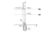
ECU10は、取得された物体の相対位置に基づいて移動軌跡を算出する。図2には、物体Aの各時刻での位置Prと、この位置Prにより算出される移動軌跡を示している。時刻nでの位置Pr(n)が履歴に記録された最新の物体Aの位置となる。例えば、ECU10は、最小二乗法等の周知の線形補間演算を用いて、各位置Prに最も近い位置を通る直線を移動軌跡として算出する。
ECU10は、算出された移動軌跡に基づいて衝突横位置Xpを算出する。衝突横位置Xpは、物体Aから自車両50までのY軸方向での距離がゼロになったと仮定した状態での当該物体の車幅方向(X軸方向)での位置である。図2において、物体Aから自車両50までのY軸方向での距離がゼロとなる位置は、X軸に相当するため、衝突横位置Xpは、移動軌跡とX軸の交点として算出される。
ECU10は、算出された衝突横位置Xpに基づいて、自車両50と物体Aとの衝突可能性を判定する。図2において、ECU10は、自車両50の前方に仮想的な判定領域Wを設定し、この判定領域W内に衝突横位置Xpが位置する場合、自車両50と物体Aとが衝突する可能性があると判定する。
そして、ECU10は、衝突する可能性があると判定した物体Aに対し、所定の作動条件に基づいて安全装置31,32を作動させる。具体的には、自車両50と物体Aとが衝突するまでの余裕時間(TTC)を算出し、このTTCに応じて安全装置を作動させる。図2では、縦軸をTTCとし、横軸を横位置とする場合の図を示している。図2では、自車両50から物体Aまでの縦軸方向での距離が遠いほどTTCが大きく、反対に自車両50から物体Aまでの縦軸方向での距離が近いほどTTCが小さくなっている。例えば、ECU10は、算出されたTTCが警報装置31の作動タイミングTTC1以下となれば、ドライバに対して物体Aが進行方向前方に存在することを警報する。また、算出されたTTCがブレーキ装置32の作動タイミングTTC2以下となれば、自車両50を所定量だけ減速させる自動ブレーキを実施する。
ところで、自車線がガードレール等の立体区画体によって区画されていることがある。例えば、自車両50と物体とがその立体区画体を隔てて存在する場合は、自車両50と物体とが近接した状態になっても衝突の可能性は低いと考えられる。この点、上述したPCSでは、自車両50に対する物体の相対位置に基づいて安全装置の作動が制御されており、ガードレール等の立体区画体の存在は考慮されていない。
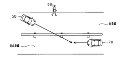
例えば、図3は、自車両50が自車線を走行し、自車線に隣接する対向車線を対向車両70が走行する状況を示しており、自車線と対向車線との間にはガードレールが設けられている。かかる状況下において、例えば、自車前方の歩行者60を避けるためハンドルが右に操作されると、一時的に自車両50の進路が対向車線側に向かうことになる。そうすると、自車両50の進路と対向車両70の移動軌跡とが交差することになり、ガードレールの向こう側の対向車両70に対して安全装置31,32が作動されることが生じ得る。この場合、不要作動となるおそれがある。
そこで、ECU10は、自車両50が走行する自車線の立体区画体を認識し、自車線の進行方向前方に物体が存在していることを判定する。そして、物体の存在が判定された場合に、その物体と自車両50との間に立体区画体があると認識されていることに基づいて、警報装置31、ブレーキ装置32の作動態様を変更するようにした。すなわち、物体の相対位置に、立体区画体の位置を加味することで、物体との衝突の可能性により適した安全装置の作動を実現している。
ECU10は、自車両50が走行する自車線の立体区画体を認識する。具体的には、ナビゲーション装置23に記憶された地図情報に基づいて立体区画体の存在を判定する。この場合、自車両50の現在地における道路情報から自車線を区画する立体区画体が存在するか否かを判定する。なお、地図情報に代えて又は加えて、レーダ装置21による物体検出や撮像装置22による物体検出を用いて、立体区画体の存在を判定してもよい。例えば、撮像装置22による物体検出では、画像データと予め記憶されたガードレールや中央分離帯等の辞書情報とを照合することで立体区画体の存在が判定される。
ECU10は、自車両50の進行方向前方に物体が存在していることを判定する。具体的には、対向車両が存在していることを判定する。対向車両は、周知の方法に基づいて判定され、例えば対地速度に基づいて判定される。この場合、ECU10は、レーダ装置21により取得された物体の相対速度と自車両50の速度とから物体の対地速度を算出し、算出した対地速度が負の値であった場合に物体が対向車両であると判定する。この場合、自車両50の進行方向における対地速度を正とする。
そして、ECU10は、対向車両の存在が判定された場合に、その対向車両と自車両50との間に立体区画体があると認識されていれば、安全装置31,32の作動条件を厳しくする側に変更する。例えば、警報装置31の作動タイミングTTC1を小さくする側に変更し、ブレーキ装置32の作動タイミングTTC2を大きくする側に変更する。つまり、安全装置が作動されにくくなる側に作動態様を変更する。一方、対向車両の存在が判定された場合に、その対向車両と自車両50との間に立体区画体があると認識されていなければ、作動条件についての厳しくする側への変更を行わない。つまりこの場合、ECU10は、通常の作動条件に基づいて安全装置31,32を作動させる。
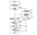
図4のフローチャートを用いて、ECU10により実施されるPCS制御の処理手順について説明する。この処理は、ECU10により所定周期で繰り返し実施される。
ステップS11では、物体検出センサ21,22の検出結果に基づいて物体の位置を取得する。本実施形態では、物体の位置として、レーダ位置と画像位置とを融合したフュージョン位置を取得する。ステップS12では、物体が対向車線を走行する対向車両であるか否かを判定する。具体的には、物体の対地速度が負の値である場合に、物体が対向車両であると判定する。ステップS12がNOの場合、つまり物体が対向車両でないと判定された場合は、ステップS13に進む。一方、ステップS12がYESの場合、つまり物体が対向車両であると判定された場合は、ステップS14に進む。
ステップS14では、地図情報に基づいて立体区画体を認識する。立体区画体として、例えばガードレールやセンターポール等を認識する。続くステップS15では、自車両50と対向車両との間に立体区画体があるか否かを判定する。具体的には、認識された立体区画体と自車両50と対向車両との相対的な位置関係に基づいて判定する。例えば、自車両50の進路に対する対向車両の移動軌跡に立体区画体が存在する場合は、自車両50と対向車両との間に立体区画体があると判定する。
ステップS15がNOの場合、つまり自車両50と対向車両との間に立体区画体がないと判定された場合は、ステップS13に進む。ステップS13では、安全装置31,32の作動タイミングとして、通常の作動タイミングを設定する。例えば、警報装置31の通常の作動タイミングとしてTTC1を設定し、ブレーキ装置32の通常の作動タイミングとしてTTC2を設定する。
一方、ステップS15がYESの場合、つまり自車両50と対向車両との間に立体区画体があると判定された場合は、ステップS16に進む。ステップS16では、安全装置31,32の作動タイミングを遅くする側に変更する。例えば、警報装置31の通常の作動タイミングをTTC1、ブレーキ装置32の通常の作動タイミングをTTC2とすると、それぞれの値を小さくする側に変更する。すなわち、安全装置31,32を作動させにくくする側に変更する。
ステップS17では、自車両50と物体との衝突可能性があるか否かを判定する。具体的には、物体の移動軌跡から求められる衝突横位置Xpが所定の範囲に属するか否かを判定する。ステップS17がYESの場合、ステップS18に進む。ステップS18では、衝突可能性がある物体に対して、安全装置の各作動タイミングであるか否かを判定する。そして、作動タイミングであると判定された場合(ステップS18:YES)は、対応する安全装置を作動させる(ステップS19)。一方、ステップS17及びステップS18がNOの場合は安全装置を作動させず、そのまま本処理を終了する。
本実施形態において、ステップS11,S12が「判定部」に相当し、ステップS14が「認識部」に相当し、ステップS16が「変更部」に相当する。
以上詳述した本実施形態によれば、以下の優れた効果が得られる。
自車両50の走行中において自車線を区画する区画部が存在する場合、物体と自車両50とが区画部を隔てて位置していれば、仮に物体と自車両50とが近接した状態となっても衝突の可能性は低いと考えられる。この点を考慮し、物体と自車両50との間に区画部があると認識されていることに基づいて、安全装置31,32の作動態様を変更するようにした。具体的には、物体と自車両50との間に区画部があると認識されていれば、安全装置31,32の作動タイミングを遅くする側に変更した。その結果、安全装置31,32が作動されにくくなり、区画部の向こう側の物体に対する不要作動を抑制することができる。一方、物体と自車両50との間に区画部があると認識されていなければ、安全装置31,32の作動タイミングの変更を行わないようにしたため、かかる物体に対しては迅速に安全装置31,32を作動させることができる。これにより、物体に対して安全装置31,32を適正に作動させることができる。
自車両50と対向車両との間に区画部が存在していれば、仮に自車両50と対向車両の移動方向が交差するような状態となっても衝突の可能性は低いと考えられる。また、区画部が立体区画体である場合は、より一層衝突の可能性は低くなると考えられる。この点を考慮し、対向車両と自車両50との間に立体区画体があると認識されていれば、安全装置31,32の作動タイミングを遅くする側に変更したため、物体との衝突の可能性をより考慮した上で安全装置31,32を作動させることができる。
センターポールや中央分離帯等は、物体検出センサ21,22による検出が困難であると考えられる。この点を考慮し、地図情報に基づいて立体区画体が存在することを認識するようにしたため、物体検出センサ21,22による検出が困難な立体区画体であっても、その存在を適切に認識することができる。
(第1実施形態の別例)
・上記実施形態では、警報装置31及びブレーキ装置32の作動タイミングをいずれも遅くする側に変更したが、いずれか一方のみを遅くする側に変更してもよい。この場合、例えば警報装置31の作動タイミングのみを遅くする側に変更するとよい。かかる構成によれば、警報装置31の作動に伴うドライバの煩わしさを軽減しつつ、ブレーキ装置32の作動が確保される。
・上記実施形態では、警報装置31及びブレーキ装置32の作動タイミングをいずれも遅くする側に変更したが、いずれか一方のみを遅くする側に変更してもよい。この場合、例えば警報装置31の作動タイミングのみを遅くする側に変更するとよい。かかる構成によれば、警報装置31の作動に伴うドライバの煩わしさを軽減しつつ、ブレーキ装置32の作動が確保される。
・立体区画体の道路からの高さを取得し、その立体区画体の高さに基づいて安全装置31,32の作動タイミングを遅くする側に変更してもよい。かかる構成について、図4のフローチャートを用いて説明する。
図4において、物体検出により対向車両が存在すると判定される(ステップS12:YES)と、ステップS14に進む。ステップS14では、立体区画体を認識するとともにその立体区画体の高さを取得する。立体区画体の高さは、例えば、立体区画体の位置とともにその立体区画体の高さが予め記憶された地図情報に基づいて取得される。また、その他にレーダ装置21や撮像装置22の入力に基づいて取得されてもよい。
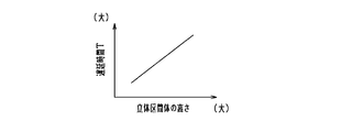
そして、続くステップS15にて自車両50と対向車両との間に立体区画体が存在すると判定されると、ステップS16に進む。ステップS16では、立体区画体の高さに基づいて作動タイミングを変更する。例えば、図5に示すように立体区画体の高さと遅延時間Tとの相関マップに基づいて変更される。ここで、遅延時間Tは、通常の作動タイミングから作動タイミングを遅らせる時間を意味している。つまり、遅延時間Tがゼロの場合は、通常の作動タイミングが設定される。図5では、立体区画体の高さが高くなるほど、遅延時間Tが大きく設定される。つまり、立体区画体の高さが高い場合(例えばガードレールの場合)、それよりも低い場合(例えば縁石の場合)に比べて、作動タイミングがより遅くなるように設定される。つまり安全装置31,32が作動されにくくなるように設定される。
立体区画体の高さが高くなるほど、その立体区画体の向こう側の対向車両との衝突の可能性は低くなると考えられる。この点を考慮し、立体区画体の高さに基づいて安全装置31,32の作動タイミングを遅くする側に変更することで、対向車両との衝突の可能性をより考慮した上で安全装置31,32を作動させることができる。
・上記実施形態では、安全装置31,32の作動態様の変更として、安全装置の作動タイミングを変更したがこれに限らない。例えば、安全装置を作動させないように作動態様を変更してもよい。
かかる構成について、図6のフローチャートを用いて説明する。本処理は、上述の図4に置き換えてECU10により所定周期で繰り返し実施される。なお図6では、図4と同様の処理について同一のステップ番号を付して説明を簡略にする。図4の処理からの変更点は、ステップS16を省略した点である。
図6では、物体検出により対向車両が存在すると判定され(ステップS12:YES)、かつ、自車両50と対向車両との間に立体区画体が存在すると判定されると(ステップS15:YES)、衝突可能性の判定を実施せずにそのまま本処理を終了する。つまり、自車両50と対向車両との間に立体区画体が存在すると判定された場合は、衝突の可能性はないとみなして、安全装置31,32を作動させない。
上記構成では、対向車両の存在が判定された場合に、その対向車両と自車両50との間に立体区画体があると認識されていれば、安全装置31,32を作動させなくするようにしたため、安全装置31,32の不要作動を好適に抑制することができる。
上記の立体区画体が存在する場合に安全装置31,32を作動させない構成において、さらに立体区画体の高さを考慮するようにしてもよい。かかる場合、例えば、図6のフローチャートにおいてステップS15では、ECU10は、自車両50と対向車両との間に立体区画体が存在しており、かつその立体区画体の高さが所定の高さHth(例えば、1m)よりも高いか否かを判定する。ステップ15がYESであれば、衝突可能性の判定を実施せずにそのまま本処理を終了する。一方、ステップ15がNOであれば、ステップS13に進み、通常の作動タイミングを設定する。つまりかかる構成では、自車両50と対向車両との間に所定の高さHth以上の立体区画体が存在すると判定された場合は、衝突の可能性はないとみなして、安全装置31,32を作動させないようにしている。
・上記実施形態では、自車両50と対向車両との間の立体区画体を認識した場合に、安全装置の作動タイミングを変更する構成としたが、対向車両以外でもよく、例えば自車両50と歩行者との間の立体区画体を認識した場合に、安全装置の作動タイミングを変更する構成としてもよい。かかる構成では、撮像画像に基づく画像データと予め記憶された歩行者の辞書情報とを照合することで、歩行者の存在が判定される。
さらに、物体の種類を判定し、判定した物体の種類に応じて作動タイミングを変更してもよい。例えば、警報装置31の作動タイミングについて言うと、物体が歩行者であれば作動タイミングをTTC1からTTC1Aに変更し、物体が対向車両であればTTC1からTTC1Bに変更する。変更後の作動タイミングは、立体区画体を考慮した上での物体毎の衝突可能性に基づいて設定されるとよい。上記の場合、例えばTTC1A>TTC1Bに設定される。
(第2実施形態)
上記第1実施形態では、区画部として、ガードレール等の自車線を区画する立体区画体を認識する構成としたのに対し、第2実施形態では、区画部として、自車線を区画する区画線を認識する構成としている。例えば、図7は、区画線L11,L12に区画された自車線を自車両50が走行し、自車線の外側を歩行者80が移動している状況を示している。図7において、自車線は自車両50の前方において右側に曲がっているものの、図7の状況下における自車両50の進路は、歩行者80の移動軌跡と交差するようになっている。かかる場合には、歩行者80に対して安全装置31,32が作動されるおそれがある。
上記第1実施形態では、区画部として、ガードレール等の自車線を区画する立体区画体を認識する構成としたのに対し、第2実施形態では、区画部として、自車線を区画する区画線を認識する構成としている。例えば、図7は、区画線L11,L12に区画された自車線を自車両50が走行し、自車線の外側を歩行者80が移動している状況を示している。図7において、自車線は自車両50の前方において右側に曲がっているものの、図7の状況下における自車両50の進路は、歩行者80の移動軌跡と交差するようになっている。かかる場合には、歩行者80に対して安全装置31,32が作動されるおそれがある。
そこで、ECU10は、区画線を認識し、自車両50と物体との間に区画線が存在しているか否かを判定する。そして、区画線が存在する場合は、安全装置の作動態様を変更する。具体的には、安全装置の作動タイミングを遅くする側に変更する。なお、区画線の認識には、周知の方法が用いられる。例えば、撮影画像にsobelフィルタ等を適用してエッジ点を抽出し、抽出したエッジ点に周知の近似法等を適用して区画線を認識する。そして、認識された区画線から、自車両50の左側で且つ自車両50の最も近くで認識された区画線を自車線の左側の区画線と認識し、自車両50の右側で且つ自車両50の最も近くで認識された区画線を自車線の右側の区画線と認識する。
なお、区画線の認識は、画像認識による方法に限らない。例えば、ECU10は、地図情報と自車位置とに基づいて区画線を認識してもよい。かかる場合、ナビゲーション装置23における地図情報には各道路の区画線の位置が含まれており、その地図上における自車位置から区画線が認識される。
第2実施形態において実施されるPCSについて、図8のフローチャートを用いて説明する。本処理は、上述の図4に置き換えてECU10により所定周期で繰り返し実施される。なお図8では、図4と同様の処理について同一のステップ番号を付して説明を簡略にする。
図8において、物体の位置が取得されると(ステップS11)、ステップS21に進む。ステップS21では、物体が歩行者であるか否かを判定する。ここでは、撮像画像から歩行者の辞書情報に基づいて判定される。ステップS21がNOの場合、つまり物体が歩行者でないと判定された場合は、ステップS13に進む。一方、ステップS21がYESの場合、つまり物体が歩行者であると判定された場合は、ステップS22に進む。
ステップS22では、撮像画像に基づいて自車線の区画線を認識する。続くステップS23では、自車両50と歩行者との間に区画線があるか否かを判定する。具体的には、認識された区画線と自車両50と歩行者との相対的な位置関係に基づいて判定する。例えば、自車両50の進路に対する歩行者の移動軌跡に区画線が存在する場合は、自車両50と歩行者との間に区画線があると判定する。
ステップS23がNOの場合、つまり自車両50と歩行者との間に区画線がないと判定された場合は、ステップS13に進む。ステップS13では、安全装置31,32の作動タイミングとして、通常の作動タイミングを設定する。一方、ステップS23がYESの場合、つまり自車両50と歩行者との間に区画線があると判定された場合は、ステップS16に進む。ステップS16では、安全装置31,32の作動タイミングを遅くする側に変更する。なお、後続の処理については上述のとおりである。
自車両50の走行中において、自車両50と歩行者とが区画線を隔てて位置していれば、仮に歩行者と自車両50とが近接した状態となっても衝突の可能性は低いと考えられる。この点を考慮し、歩行者と自車両50との間に区画線があると認識されていれば、安全装置31,32の作動タイミングを遅くする側に変更した。その結果、安全装置31,32が作動されにくくなり、区画線の向こう側の歩行者に対する不要作動を抑制することができる。一方、歩行者と自車両50との間に区画線があると認識されていなければ、作動タイミングの変更を行わないようにしたため、かかる歩行者に対しては迅速に安全装置31,32を作動させることができる。
(第2実施形態の別例)
・上記実施形態では、自車両50と歩行者との間の区画線を認識した場合に、安全装置の作動タイミングを変更する構成としたが、歩行者以外でもよく、例えば自車両50と対向車両との間の区画線を認識した場合に、安全装置の作動タイミングを変更する構成としてもよい。
・上記実施形態では、自車両50と歩行者との間の区画線を認識した場合に、安全装置の作動タイミングを変更する構成としたが、歩行者以外でもよく、例えば自車両50と対向車両との間の区画線を認識した場合に、安全装置の作動タイミングを変更する構成としてもよい。
(他の別例)
・上記実施形態では、物体として対向車両や歩行者を検出したが、これに限らず、例えば自転車やバイクなどの二輪車を検出してもよい。
・上記実施形態では、物体として対向車両や歩行者を検出したが、これに限らず、例えば自転車やバイクなどの二輪車を検出してもよい。
本開示は、実施例に準拠して記述されたが、本開示は当該実施例や構造に限定されるものではないと理解される。本開示は、様々な変形例や均等範囲内の変形をも包含する。加えて、様々な組み合わせや形態、さらには、それらに一要素のみ、それ以上、あるいはそれ以下、を含む他の組み合わせや形態をも、本開示の範疇や思想範囲に入るものである。
Claims (6)
- 自車両周辺の物体を検出する物体検出センサ(21,22)を備える車両(50)に適用され、前記物体検出センサの検出結果に基づいて、前記物体との衝突を回避又は軽減する安全装置(31,32)を作動させる車両制御装置(10)であって、
前記自車両が走行する自車線の区画部を認識する認識部と、
前記自車両の進行方向前方に、前記物体検出センサにより検出された物体が存在していることを判定する判定部と、
前記判定部により前記物体の存在が判定された場合に、その物体と前記自車両との間に前記区画部があると認識されていることに基づいて、前記安全装置の作動態様を変更する変更部と、
を備える車両制御装置。 - 前記安全装置は、所定の作動条件を満たすことで作動されるものであり、
前記変更部は、前記判定部により前記物体の存在が判定された場合において、その物体と前記自車両との間に前記区画部があると認識されていれば、前記作動条件を厳しくする側へ変更し、前記判定部により前記物体の存在が判定された場合において、その物体と前記自車両との間に前記区画部があると認識されていなければ、前記作動条件の前記厳しくする側への変更を行わない請求項1に記載の車両制御装置。 - 前記変更部は、前記判定部により前記物体の存在が判定された場合において、その物体と前記自車両との間に前記区画部があると認識されていれば、前記安全装置を作動させなくするように前記作動態様を変更する請求項1に記載の車両制御装置。
- 前記判定部は、前記自車線に隣接する対向車線を走行する対向車両の存在を判定し、
前記変更部は、前記判定部により前記対向車両の存在が判定された場合に、その対向車両と前記自車両との間に前記区画部があると認識されていることに基づいて、前記作動態様を変更する請求項1乃至3のいずれか1項に記載の車両制御装置。 - 前記区画部は、前記自車線と、前記自車線に隣接する隣接車線又は歩道部とを区画する立体区画体であり、
前記認識部は、前記立体区画体が存在していることを認識する請求項1乃至4のいずれか1項に記載の車両制御装置。 - 前記認識部は、地図情報に基づいて前記立体区画体が存在することを認識する請求項5に記載の車両制御装置。
Applications Claiming Priority (2)
| Application Number | Priority Date | Filing Date | Title |
|---|---|---|---|
| JP2017127328A JP6733616B2 (ja) | 2017-06-29 | 2017-06-29 | 車両制御装置 |
| JP2017-127328 | 2017-06-29 |
Publications (1)
| Publication Number | Publication Date |
|---|---|
| WO2019003923A1 true WO2019003923A1 (ja) | 2019-01-03 |
Family
ID=64740631
Family Applications (1)
| Application Number | Title | Priority Date | Filing Date |
|---|---|---|---|
| PCT/JP2018/022592 WO2019003923A1 (ja) | 2017-06-29 | 2018-06-13 | 車両制御装置 |
Country Status (2)
| Country | Link |
|---|---|
| JP (1) | JP6733616B2 (ja) |
| WO (1) | WO2019003923A1 (ja) |
Families Citing this family (2)
| Publication number | Priority date | Publication date | Assignee | Title |
|---|---|---|---|---|
| JP7192600B2 (ja) * | 2019-03-20 | 2022-12-20 | 株式会社デンソー | 警報装置 |
| JP7275000B2 (ja) * | 2019-10-11 | 2023-05-17 | 株式会社デンソー | 制御装置 |
Citations (2)
| Publication number | Priority date | Publication date | Assignee | Title |
|---|---|---|---|---|
| JP2016021210A (ja) * | 2014-07-16 | 2016-02-04 | クラリオン株式会社 | 車載器、サーバー装置および注意喚起システム |
| WO2017010333A1 (ja) * | 2015-07-10 | 2017-01-19 | 田山 修一 | 車輌用画像表示システム及び方法 |
-
2017
- 2017-06-29 JP JP2017127328A patent/JP6733616B2/ja active Active
-
2018
- 2018-06-13 WO PCT/JP2018/022592 patent/WO2019003923A1/ja active Application Filing
Patent Citations (2)
| Publication number | Priority date | Publication date | Assignee | Title |
|---|---|---|---|---|
| JP2016021210A (ja) * | 2014-07-16 | 2016-02-04 | クラリオン株式会社 | 車載器、サーバー装置および注意喚起システム |
| WO2017010333A1 (ja) * | 2015-07-10 | 2017-01-19 | 田山 修一 | 車輌用画像表示システム及び方法 |
Also Published As
| Publication number | Publication date |
|---|---|
| JP2019012322A (ja) | 2019-01-24 |
| JP6733616B2 (ja) | 2020-08-05 |
Similar Documents
| Publication | Publication Date | Title |
|---|---|---|
| CN110281920B (zh) | 车辆控制装置、车辆控制方法以及存储介质 | |
| JP5345350B2 (ja) | 車両の運転支援装置 | |
| CN108541325B (zh) | 驾驶辅助装置以及驾驶辅助方法 | |
| CN109204311B (zh) | 一种汽车速度控制方法和装置 | |
| JP6412457B2 (ja) | 運転支援装置、及び運転支援方法 | |
| WO2016159288A1 (ja) | 物標存在判定方法及び装置 | |
| WO2016158944A1 (ja) | 車両制御装置及び車両制御方法 | |
| WO2018074287A1 (ja) | 車両制御装置 | |
| JP5185663B2 (ja) | 車両用運転支援装置 | |
| WO2019058446A1 (ja) | 車両制御装置、車両制御方法、及びプログラム | |
| US10747219B2 (en) | Processing apparatus, vehicle, processing method, and storage medium | |
| JP7085371B2 (ja) | 車両制御装置、車両制御方法、およびプログラム | |
| WO2019073511A1 (ja) | 車両制御装置、車両制御方法、及びプログラム | |
| JP2016192164A (ja) | 物体検知装置、及び物体検知方法 | |
| JP7059786B2 (ja) | 車外報知装置 | |
| CN112447057B (zh) | 停止线位置推定装置及车辆控制系统 | |
| JP2017068461A (ja) | 車両の運転支援装置 | |
| JP7275623B2 (ja) | 運転支援装置 | |
| JP2019046143A (ja) | 走行支援装置 | |
| JP5210064B2 (ja) | 車両の衝突防止装置 | |
| WO2019009032A1 (ja) | 車両制御装置 | |
| JP5452004B2 (ja) | 車両の運転支援装置 | |
| JP6733616B2 (ja) | 車両制御装置 | |
| JP7324600B2 (ja) | 車両制御装置、車両制御方法、およびプログラム | |
| JP7239353B2 (ja) | 車両における制動支援制御装置、制動支援制御システムおよび制動支援制御方法 |
Legal Events
| Date | Code | Title | Description |
|---|---|---|---|
| 121 | Ep: the epo has been informed by wipo that ep was designated in this application |
Ref document number: 18823552 Country of ref document: EP Kind code of ref document: A1 |
|
| NENP | Non-entry into the national phase |
Ref country code: DE |
|
| 122 | Ep: pct application non-entry in european phase |
Ref document number: 18823552 Country of ref document: EP Kind code of ref document: A1 |