WO2018230145A1 - 内視鏡用処置具 - Google Patents
内視鏡用処置具 Download PDFInfo
- Publication number
- WO2018230145A1 WO2018230145A1 PCT/JP2018/015860 JP2018015860W WO2018230145A1 WO 2018230145 A1 WO2018230145 A1 WO 2018230145A1 JP 2018015860 W JP2018015860 W JP 2018015860W WO 2018230145 A1 WO2018230145 A1 WO 2018230145A1
- Authority
- WO
- WIPO (PCT)
- Prior art keywords
- loop
- wire
- length
- sheath
- snare
- Prior art date
Links
- OLNIVZWUZLROSE-UHFFFAOYSA-N CC(C)(CC(CCN)=C)NC Chemical compound CC(C)(CC(CCN)=C)NC OLNIVZWUZLROSE-UHFFFAOYSA-N 0.000 description 1
Images


Classifications
-
- A—HUMAN NECESSITIES
- A61—MEDICAL OR VETERINARY SCIENCE; HYGIENE
- A61B—DIAGNOSIS; SURGERY; IDENTIFICATION
- A61B17/00—Surgical instruments, devices or methods, e.g. tourniquets
- A61B17/32—Surgical cutting instruments
- A61B17/3205—Excision instruments
- A61B17/32056—Surgical snare instruments
-
- A—HUMAN NECESSITIES
- A61—MEDICAL OR VETERINARY SCIENCE; HYGIENE
- A61B—DIAGNOSIS; SURGERY; IDENTIFICATION
- A61B18/00—Surgical instruments, devices or methods for transferring non-mechanical forms of energy to or from the body
- A61B18/04—Surgical instruments, devices or methods for transferring non-mechanical forms of energy to or from the body by heating
- A61B18/12—Surgical instruments, devices or methods for transferring non-mechanical forms of energy to or from the body by heating by passing a current through the tissue to be heated, e.g. high-frequency current
- A61B18/14—Probes or electrodes therefor
- A61B18/1492—Probes or electrodes therefor having a flexible, catheter-like structure, e.g. for heart ablation
-
- A—HUMAN NECESSITIES
- A61—MEDICAL OR VETERINARY SCIENCE; HYGIENE
- A61B—DIAGNOSIS; SURGERY; IDENTIFICATION
- A61B18/00—Surgical instruments, devices or methods for transferring non-mechanical forms of energy to or from the body
- A61B18/04—Surgical instruments, devices or methods for transferring non-mechanical forms of energy to or from the body by heating
- A61B18/12—Surgical instruments, devices or methods for transferring non-mechanical forms of energy to or from the body by heating by passing a current through the tissue to be heated, e.g. high-frequency current
- A61B18/1206—Generators therefor
-
- A—HUMAN NECESSITIES
- A61—MEDICAL OR VETERINARY SCIENCE; HYGIENE
- A61B—DIAGNOSIS; SURGERY; IDENTIFICATION
- A61B17/00—Surgical instruments, devices or methods, e.g. tourniquets
- A61B17/00234—Surgical instruments, devices or methods, e.g. tourniquets for minimally invasive surgery
- A61B2017/00292—Surgical instruments, devices or methods, e.g. tourniquets for minimally invasive surgery mounted on or guided by flexible, e.g. catheter-like, means
- A61B2017/0034—Surgical instruments, devices or methods, e.g. tourniquets for minimally invasive surgery mounted on or guided by flexible, e.g. catheter-like, means adapted to be inserted through a working channel of an endoscope
-
- A—HUMAN NECESSITIES
- A61—MEDICAL OR VETERINARY SCIENCE; HYGIENE
- A61B—DIAGNOSIS; SURGERY; IDENTIFICATION
- A61B17/00—Surgical instruments, devices or methods, e.g. tourniquets
- A61B17/00234—Surgical instruments, devices or methods, e.g. tourniquets for minimally invasive surgery
- A61B2017/00358—Snares for grasping
-
- A—HUMAN NECESSITIES
- A61—MEDICAL OR VETERINARY SCIENCE; HYGIENE
- A61B—DIAGNOSIS; SURGERY; IDENTIFICATION
- A61B17/00—Surgical instruments, devices or methods, e.g. tourniquets
- A61B2017/00831—Material properties
- A61B2017/00862—Material properties elastic or resilient
-
- A—HUMAN NECESSITIES
- A61—MEDICAL OR VETERINARY SCIENCE; HYGIENE
- A61B—DIAGNOSIS; SURGERY; IDENTIFICATION
- A61B17/00—Surgical instruments, devices or methods, e.g. tourniquets
- A61B17/22—Implements for squeezing-off ulcers or the like on the inside of inner organs of the body; Implements for scraping-out cavities of body organs, e.g. bones; Calculus removers; Calculus smashing apparatus; Apparatus for removing obstructions in blood vessels, not otherwise provided for
- A61B17/221—Gripping devices in the form of loops or baskets for gripping calculi or similar types of obstructions
- A61B2017/2212—Gripping devices in the form of loops or baskets for gripping calculi or similar types of obstructions having a closed distal end, e.g. a loop
-
- A—HUMAN NECESSITIES
- A61—MEDICAL OR VETERINARY SCIENCE; HYGIENE
- A61B—DIAGNOSIS; SURGERY; IDENTIFICATION
- A61B18/00—Surgical instruments, devices or methods for transferring non-mechanical forms of energy to or from the body
- A61B2018/00053—Mechanical features of the instrument of device
- A61B2018/00059—Material properties
- A61B2018/00071—Electrical conductivity
- A61B2018/00077—Electrical conductivity high, i.e. electrically conducting
-
- A—HUMAN NECESSITIES
- A61—MEDICAL OR VETERINARY SCIENCE; HYGIENE
- A61B—DIAGNOSIS; SURGERY; IDENTIFICATION
- A61B18/00—Surgical instruments, devices or methods for transferring non-mechanical forms of energy to or from the body
- A61B2018/00053—Mechanical features of the instrument of device
- A61B2018/00172—Connectors and adapters therefor
- A61B2018/00178—Electrical connectors
-
- A—HUMAN NECESSITIES
- A61—MEDICAL OR VETERINARY SCIENCE; HYGIENE
- A61B—DIAGNOSIS; SURGERY; IDENTIFICATION
- A61B18/00—Surgical instruments, devices or methods for transferring non-mechanical forms of energy to or from the body
- A61B2018/00982—Surgical instruments, devices or methods for transferring non-mechanical forms of energy to or from the body combined with or comprising means for visual or photographic inspections inside the body, e.g. endoscopes
-
- A—HUMAN NECESSITIES
- A61—MEDICAL OR VETERINARY SCIENCE; HYGIENE
- A61B—DIAGNOSIS; SURGERY; IDENTIFICATION
- A61B18/00—Surgical instruments, devices or methods for transferring non-mechanical forms of energy to or from the body
- A61B18/04—Surgical instruments, devices or methods for transferring non-mechanical forms of energy to or from the body by heating
- A61B18/12—Surgical instruments, devices or methods for transferring non-mechanical forms of energy to or from the body by heating by passing a current through the tissue to be heated, e.g. high-frequency current
- A61B18/14—Probes or electrodes therefor
- A61B2018/1405—Electrodes having a specific shape
- A61B2018/1407—Loop
- A61B2018/141—Snare
-
- A—HUMAN NECESSITIES
- A61—MEDICAL OR VETERINARY SCIENCE; HYGIENE
- A61B—DIAGNOSIS; SURGERY; IDENTIFICATION
- A61B18/00—Surgical instruments, devices or methods for transferring non-mechanical forms of energy to or from the body
- A61B18/04—Surgical instruments, devices or methods for transferring non-mechanical forms of energy to or from the body by heating
- A61B18/12—Surgical instruments, devices or methods for transferring non-mechanical forms of energy to or from the body by heating by passing a current through the tissue to be heated, e.g. high-frequency current
- A61B18/14—Probes or electrodes therefor
- A61B2018/1405—Electrodes having a specific shape
- A61B2018/144—Wire
-
- A—HUMAN NECESSITIES
- A61—MEDICAL OR VETERINARY SCIENCE; HYGIENE
- A61B—DIAGNOSIS; SURGERY; IDENTIFICATION
- A61B18/00—Surgical instruments, devices or methods for transferring non-mechanical forms of energy to or from the body
- A61B18/04—Surgical instruments, devices or methods for transferring non-mechanical forms of energy to or from the body by heating
- A61B18/12—Surgical instruments, devices or methods for transferring non-mechanical forms of energy to or from the body by heating by passing a current through the tissue to be heated, e.g. high-frequency current
- A61B18/14—Probes or electrodes therefor
- A61B2018/1475—Electrodes retractable in or deployable from a housing
Definitions
- the present invention relates to an endoscope treatment tool.
- This application claims priority based on Japanese Patent Application No. 2017-115905 filed in Japan on June 13, 2017, the contents of which are incorporated herein by reference.
- a snare has been used as an endoscopic treatment tool for transscopically removing a tissue such as a polyp in the digestive tract.
- a snare for an endoscope has a sheath, an operation wire that is inserted into the sheath so as to be able to advance and retreat in the axial direction, and a snare loop including an elastic wire connected to the operation wire.
- the snare loop is formed by bending back one elastic wire at the tip of the snare loop. In such a snare, the snare loop protrudes and retracts from the distal end of the sheath by moving the operation wire back and forth in the axial direction.
- the open width of the snare loop expands due to its own elasticity.
- the snare loop is narrowed.
- the operator inserts the snare into the body through the endoscope until the snare is located in the vicinity of a tissue to be excised, for example, a polyp.
- a tissue to be excised for example, a polyp.
- the surgeon applies a snare loop to the root of the tissue to be excised and pulls the operation wire toward the proximal end side.
- a part of the snare loop is drawn into the sheath, and the opening width of the snare loop is reduced.
- the tissue to be excised is bound with a snare loop and excised from the digestive tract.
- the opening width of the snare loop often decreases rapidly.
- the open width of the snare loop may suddenly become half of the maximum open width or 40% or less for a small amount of retraction.
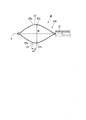
- the snare loop of the endoscope snare described in Patent Document 1 has a first main bent portion, a second main bent portion, and a third main bent portion in order from the distal end side, and has a hexagonal shape. Is formed.
- the proximal end side of the snare loop of the endoscope snare described in Patent Document 1 is bound by a connecting pipe and is inserted into the sheath so as to be able to advance and retreat.
- the snare loop 100 of the endoscope snare described in Patent Document 1 has a length A from the first main bent portion 11 to the second main bent portion 12 and a second main bent portion 12. Of the length B from the bent portion 12 to the third main bent portion 13 and the length C from the third main bent portion 13 to the rear end binding portion 3, the third main bent portion 13 to the rear end The length C to the binding part 3 is the longest. More specifically, in the snare loop 100 of the endoscope snare described in Patent Document 1, the length A is 2 times to 3 times the length B, and the length C is 5 times to 10 times the length A. It is formed in less than double.
- the snare for an endoscope described in Patent Document 1 can be captured and excised from a small polyp to a large polyp by adjusting the size of the snare loop 100.
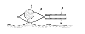
- the operator When performing a treatment on a large polyp using the endoscope snare described in Patent Document 1, as shown in FIG. 10, the operator removes the snare loop 100 of the endoscope snare from the distal end of the sheath 102. When protruding, the snare loop 100 swells greatly due to its own elasticity. In this state, the surgeon can capture the polyp by applying the snare loop 100 to the polyp. At this time, since the length C from the third main bent portion 13 of the snare loop to the rear end bundling portion 3 is long, the snare loop 100 has a configuration in which the entire length becomes long and gently spreads.
- the change in the opening width of the snare loop 100 accompanying the operation of the surgeon becomes relatively gradual.
- the tissue to be excised may be excised by the operator's operation, and normal tissue that is not desired to be excised may be excised.
- the operator pulls the operation wire 104 toward the proximal end side of the sheath 102.
- the size of the snare loop 100 needs to be adjusted.
- the size of the snare loop 100 since the total length of the snare loop 100 is long, there is a possibility that many normal tissues that are not desired to be excised enter the snare loop 100 in this process.
- the present invention provides an endoscopic treatment tool that can finely adjust the opening width of the snare loop and can be excised with an appropriate excision range and excision amount for the tissue to be excised. Objective.
- An endoscope treatment tool includes a sheath that can be inserted into a channel of an endoscope, and a long portion that is inserted into the sheath so as to be able to advance and retreat in its longitudinal axis direction.
- the wire is arranged at the tip of the long portion and is bent into a loop shape, and can be deformed so that the size of the loop changes by projecting and retracting from the sheath by advancing and retracting the long portion.
- a loop portion wherein the loop portion includes a first bent portion, a pair of second bent portions, a pair of third bent portions, and a fourth bent portion in order from the distal end toward the proximal end.
- the length of the proximal wire portion connecting the pair of third bent portions and the fourth bent portion is longer than the length of the distal wire portion connecting the first bent portion and the pair of second bent portions.
- the tip wire portion is long and the pair of second bent portions and the pair of third bent portions are Longer than the length of the intermediate wire portion connecting the first and second bent portions from the first bent portion in the longitudinal axis direction in a state in which the loop portion protrudes from the sheath to the maximum by the advance and retreat operation of the long portion.
- the first length that is up to 1.5 times is not less than 1.5 times the first width that is the maximum dimension of the loop portion in the direction orthogonal to the longitudinal axis, and the proximal wire portion
- the length of the intermediate wire portion is not less than 40% and not more than 60% of the first length, and the length of the intermediate wire portion is not less than 20% and not more than 30% of the first width.
- a state where 2/3 of the first length of the loop portion protrudes from the sheath a state where 2/3 of the first length of the loop portion protrudes from the sheath.
- the dimension of the loop part in the direction orthogonal to the longitudinal axis may be 40% or more and less than 60% of the first width.
- an intermediate position of the loop part is arranged in the intermediate wire part in the longitudinal axis direction of the loop part. May be.
- the loop portion has a distal-end bending angle formed by the distal-end wire portion and the intermediate wire portion, It may be larger than the bending angle on the base end side formed by the intermediate wire portion and the base end wire portion.
- the open width of the snare loop can be finely adjusted, and the tissue to be excised can be excised with an appropriate excision range and excision amount.
- FIG. 2B is an enlarged view showing a partial configuration of the snare loop in FIG. 2A. It is a figure which shows operation
- FIGS. 1 to 5 an endoscope treatment tool according to an embodiment of the present invention will be described with reference to FIGS. 1 to 5.
- FIG. 1 is a diagram showing an overall configuration of an endoscope treatment tool according to the present embodiment.
- FIG. 2A is a diagram illustrating a configuration of a snare loop of the endoscope treatment tool according to the present embodiment.
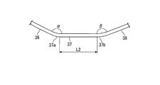
- 2B is an enlarged view showing a configuration of a part of the snare loop of the endoscope treatment tool according to the present embodiment, and is an enlarged view of a portion surrounded by a two-dot chain line in FIG. 2A.
- FIG. 3 is a diagram illustrating an operation when using the endoscope treatment tool according to the present embodiment.
- FIG. 4 is a diagram illustrating an operation of drawing a part of the snare loop of the endoscope treatment tool according to the present embodiment into the sheath.
- FIG. 5 is a diagram illustrating an operation when using the endoscope treatment tool according to the present embodiment.
- the endoscope treatment tool 1 according to the present embodiment includes a sheath 10, a snare wire 20, and an operation unit 40.
- the sheath 10 of the endoscope treatment tool 1 extends along the longitudinal axis X, and is formed in a long shape so that it can be inserted into a body cavity.
- the sheath 10 is made of an insulating material, for example, a fluororesin such as PTFE (polytetrafluoroethylene).
- the sheath 10 has flexibility, and is formed so as to be able to be inserted into and removed from a treatment instrument channel (not shown) of an endoscope along a curved shape such as a luminal tissue in a body cavity.
- the snare wire 20 includes a loop portion 21 provided on the distal end side and an operation wire (long portion) 22 provided on the proximal end side.
- the snare wire 20 is conductive and can be energized with a high-frequency current.
- the snare wire 20 according to the present embodiment is formed by bending a single elastic wire, for example, a stranded wire of a stainless steel wire, it can be repeatedly deformed. Therefore, the surgeon can perform an operation of re-grabbing the resection object using the snare wire 20 and an operation of sequentially capturing a plurality of different resection objects using the snare wire 20.
- the snare wire 20 according to the present embodiment is formed with a wire diameter of about 0.3 mm, and is thinner than the conventional high-frequency dedicated snare wire 0.47 mm. Therefore, the surgeon can perform both treatments by excising the tissue by applying a high-frequency current to the snare wire 20 and excising the tissue by binding the tissue with the snare wire 20 without applying the high-frequency current. .
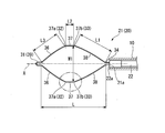
- the loop portion 21 on the distal end side of the snare wire 20 is a substantially hexagonal loop formed symmetrically with respect to the longitudinal axis X of the sheath 10.
- the loop portion 21 includes a first bent portion 31, a pair of second bent portions 32, a pair of third bent portions 33, and a fourth bent portion 34 in order from the distal end side toward the proximal end side.
- Each of the first bent portion 31, the pair of second bent portions 32, the pair of third bent portions 33, and the fourth bent portion 34 is bent convexly outwardly of the loop shape formed by the loop portion 21. Configured.
- the fourth bent portion 34 provided at the proximal end 21 a of the loop portion 21 is connected to the distal end 22 a of the operation wire 22.
- the first bent portion 31 has a protrusion 39 formed by bending an elastic wire.
- the shape of the protrusion 39 of the loop portion 21 does not change even when the loop portion 21 is advanced or retracted from the distal end opening of the sheath 10.
- the projection 39 opens the loop portion 21 against the pushing force acting on the loop portion 21.
- the loop portion 21 includes a pair of distal wire portions 36, a pair of intermediate wire portions 37, and a pair of proximal wire portions 38 in order from the distal end side toward the proximal end side.
- the pair of tip wire portions 36 is a region of the snare wire 20 provided between the first bent portion 31 and the pair of second bent portions 32.
- the pair of intermediate wire portions 37 is a region of the snare wire 20 provided between the pair of second bent portions 32 and the pair of third bent portions 33.
- the pair of proximal end wire portions 38 is a region of the snare wire 20 provided between the pair of third bent portion 33 and the fourth bent portion 34.
- the pair of intermediate wire portions 37 of the loop portion 21 are substantially parallel to each other.
- the length of the proximal wire portion 38 is defined as L1
- the length of the intermediate wire portion 37 is defined as L2
- the length of the distal wire portion 36 is defined as L3.
- the intermediate wire portion 37 of the loop portion 21 of the endoscope treatment tool 1 has a distal end portion 37a and a proximal end portion 37b.
- the distal end portion 37 a of the intermediate wire portion 37 is a connecting portion between the intermediate wire portion 37 and the distal wire portion 36.
- the proximal end portion 37 b of the intermediate wire portion 37 is a connecting portion between the intermediate wire portion 37 and the proximal end wire portion 38.
- the loop portion 21 protrudes completely from the opening formed at the distal end of the sheath 10. At that time, as a result of the loop part 21 expanding due to the elasticity of the elastic wire, the loop part 21 has the largest loop-shaped area formed by the loop part 21. In this state, along the longitudinal axis X of the sheath 10, the distance from the fourth bent portion on the proximal end side of the loop portion 21 to the first bent portion 31 on the distal end side is determined in the longitudinal axis direction of the loop portion 21. It is defined as a length (first length) L.
- the opening width of the loop portion 21 in the direction orthogonal to the longitudinal axis X of the sheath 10 is set to the maximum opening width of the loop portion 21.
- the maximum opening width W ⁇ b> 1 of the loop portion 21 is substantially equal to the distance between the pair of intermediate wire portions 37.
- the length L in the longitudinal axis direction of the loop portion 21 is the maximum opening of the loop portion 21 in a state where the loop portion 21 is completely projected from the opening provided at the distal end of the sheath 10.
- the width W1 is 1.5 to 2 times the width W1.
- the length L1 of the proximal end wire portion 38 is set longer than the length L3 of the distal end wire portion 36.
- the length L3 of the tip wire portion 36 is set longer than the length L2 of the intermediate wire portion 37. That is, in the loop portion 21 according to the present embodiment, the length L1 of the proximal end wire portion 38, the length L2 of the intermediate wire portion 37, and the length L3 of the distal end wire portion 36 are in a relationship of L1> L3> L2. Meet.
- the length L1 of the proximal end wire portion 38 is not less than 40% and not more than 60% of the length L in the longitudinal axis direction of the loop portion 21, and the length L2 of the intermediate wire portion 37 is The maximum opening width W1 of the loop portion 21 is 20% or more and 30% or less.
- Each configuration of the endoscope treatment tool 1 according to the present embodiment may be appropriately selected in accordance with an actual use situation as long as the above dimensional relationship is satisfied.
- Each configuration of the loop portion 21 of the endoscope treatment tool 1 according to the present embodiment may be formed with an appropriate dimensional change width in accordance with an actual use situation and a manufacturing process.
- the tip wire portion 36 and the intermediate wire portion 37 are connected adjacent to each other.
- the adjacent tip wire portion 36 and the intermediate wire portion 37 form a tip end side bending angle ⁇ .
- the adjacent intermediate wire portion 37 and the proximal end wire portion 38 form a proximal end side bending angle ⁇ .
- the distal end side bending angle ⁇ is larger than the proximal end side bending angle ⁇ .
- the intermediate position of the loop portion 21 may be arranged in the intermediate wire portion 37 along the direction of the longitudinal axis X of the sheath 10.
- a portion of the substantially hexagonal shape of the loop portion 21 whose length in the longitudinal axis direction is L / 2 may be located in the intermediate wire portion 37.
- the operation unit 40 of the present embodiment includes an operation unit main body 41 connected to the proximal end portion of the sheath 10, a slider 42 attached to the operation unit main body 41, and a connector 43.
- the operation wire 22 is connected to the slider 42. Therefore, the snare wire 20 is moved back and forth with respect to the sheath 10 by moving the slider 42 forward and backward with respect to the operation unit main body 41.
- the loop portion 21 protrudes from the opening provided at the distal end of the sheath 10.
- the loop portion 21 is sequentially accommodated in the sheath 10.
- the connector 43 can be connected to a high frequency power supply device (not shown), and can supply a high frequency current to the operation wire 22. Since the operation wire 22 is electrically connected to the loop portion 21, the high frequency current supplied from the high frequency power supply device is transmitted to the loop portion 21 through the operation wire 22.
- the operator inserts the endoscope into the patient's body cavity by a known technique, guides the distal end of the endoscope to the position of the polyp P to be excised, and places the polyp P in the field of view of the endoscope. Capture. Then, the operator inserts the endoscope treatment tool 1 according to the present embodiment into the endoscope and protrudes from the opening on the distal end side of the endoscope, and then, as shown in FIG. Forty sliders 42 are slid to the front end side with respect to the operation unit main body 41.
- the surgeon hangs the loop portion 21 on the polyp P in the first state. Subsequently, the surgeon slides the slider 42 of the operation unit 40 toward the proximal end side with respect to the operation unit main body 41. As a result, the proximal end side of the loop portion 21 is drawn into the sheath 10, and the root of the polyp P is bound by the loop portion 21.
- the operator After the root of the polyp P is bound by the loop portion 21, the operator operates a high-frequency power supply device (not shown) to supply a high-frequency current to the endoscope treatment tool 1.
- a high frequency flows through the loop portion 21, the polyp P tightly bound by the loop portion 21 is excised while being cauterized.
- the snare wire 20 according to the present embodiment is formed thin, for example, with a wire diameter of about 0.3 mm. Therefore, the surgeon can cut off the polyp P by an operation of moving the loop portion 21 further to the proximal end side in a state where the root of the polyp P is tightly bound by the loop portion 21 without flowing high-frequency current.
- the operator adjusts the loop portion 21 from the first state to a state in which the size of the loop shape formed by the loop portion 21 matches the size of the polyp P.
- the operator slides the slider 42 of the operation unit 40 toward the proximal end side with respect to the operation unit main body 41, and a part of the proximal end side of the loop portion 21 is attached to the sheath 10. Pull in.
- the left side of FIG. 4 shows an operation in which the loop portion 21 of the snare wire 20 of the endoscope treatment tool 1 according to the present embodiment is drawn into the sheath 10.
- the opening width of the loop portion 21 is the first width. From W1, the second opening width (second width) W2, the third opening width (third width) W3, and the fourth opening width (fourth width) W4 decrease in this order.
- W1 the second opening width (second width) W2
- W3 the third opening width (third width) W3
- W4 the fourth opening width (fourth width) W4 decrease in this order.
- the opening width of the loop portion is changed from the first width W1 to the fifth opening width ( The fifth width W5, the sixth opening width (sixth width) W6, and the seventh opening width (seventh width) W7 are reduced in this order.
- the fifth width W5 is smaller than the second width W2
- the sixth width W6 is smaller than the third width W3
- the seventh width W7 is smaller than the fourth width W4.
- the pair of distal wire portions 36, the pair of intermediate wire portions 37, and the pair of proximal end wire portions 38 move toward the proximal end side.
- the opening width of the loop shape formed by the loop portion 21 is reduced.
- the proximal end portion 37 b of the intermediate wire portion 37 moves to the proximal end side in the direction of the longitudinal axis X by pulling the proximal end wire portion 38, while the longitudinal axis of the sheath 10 in the direction orthogonal to the longitudinal axis X.
- Approach X is
- the distal end portion 37 a of the intermediate wire portion 37 moves away from the longitudinal axis X of the sheath 10 in the direction orthogonal to the longitudinal axis X while moving to the proximal end side in the longitudinal axis X direction by pulling the proximal end wire portion 38.
- the proximal end side bending angle ⁇ formed by the intermediate wire portion 37 and the proximal end wire portion 38 increases, and the distal end side bending formed by the distal end wire portion 36 and the intermediate wire portion 37.
- the angle ⁇ decreases.
- the loop portion 21 protruding from the opening on the distal end side of the sheath 10 is The shape is substantially rhombus (second state).
- the fourth opening width W4 which is the opening width of the loop portion 21 in the direction perpendicular to the longitudinal axis X of the sheath, is 40% or more and less than 60% of the first width W1 of the loop portion 21.
- the proximal-side bending angle ⁇ formed by the intermediate wire portion 37 and the proximal wire portion 38 becomes approximately 180 degrees, and the distal wire portion 36 and the intermediate wire portion 37 are The leading end side bending angle ⁇ is the minimum value.
- the proximal end portion 37 b of the intermediate wire portion 37 is located outside the sheath 10.
- the open width of the loop portion of the snare wire W7 is not less than 30% and not more than 35% of the first width W1 of the loop. That is, in the snare wire that does not have the intermediate wire portion 37, it can be confirmed that the opening width of the loop is drastically reduced as a result of drawing the snare wire toward the proximal end at about L / 3.
- the surgeon hangs the loop portion 21 in the second state on the polyp P. Thereafter, as in the case where the polyp P described above is large, the surgeon passes a high-frequency current through the loop portion 21 and excises the polyp P that is bound by the loop portion 21. The surgeon can also remove the polyp P by an operation of moving the loop portion 21 further to the proximal end side in a state where the root of the polyp P is tightly bound by the loop portion 21 without flowing high-frequency current. In the present embodiment, it has been described that the surgeon hangs the loop portion 21 in the second state on the polyp P. However, within the range of the first width W1 to the fourth width W4 according to the actual size of the polyp P. Thus, the operator can appropriately adjust the opening width of the loop portion 21 by the operation of retracting the loop portion 21.
- surgeon takes out the polyp P after excision from the body using a known tissue collecting device (not shown), pulls out the endoscope treatment tool 1 from the body cavity, and completes a series of treatments.
- the length L in the longitudinal axis direction is 1.5 to 2 times the first width W1 of the loop portion 21, And the relationship of L1>L3> L2 is satisfied.
- the length L1 of the proximal end wire portion 38 is 40% or more and 60% or less of the first length L of the loop portion 21.
- the opening width of the snare loop when adjusting the opening width of the snare loop, there is a possibility that a lot of normal tissue that is not desired to be removed enters the snare loop.
- the length of the loop portion is short, in order to secure an opening width in accordance with the size of the polyp P, it is necessary to attach a crease that bends the elastic wire greatly outward from the axial direction of the sheath of the endoscope treatment instrument. There is. In such a case, when the loop portion is hung on the polyp P and pulled into the sheath of the treatment instrument for endoscope, the opening width of the loop portion may rapidly decrease.
- the loop portion 21 since the length L of the loop portion 21 can be suppressed from being excessively long, the loop portion 21 is pushed out from the opening on the distal end side of the endoscope. As a result, it is possible to maintain the force necessary to press against the tissue and to form a loop shape close to a circle according to the shape of the polyp P.
- the loop portion 21 is drawn into the sheath 10.
- the opening width of the loop portion 21 can be prevented from being rapidly reduced. That is, according to the endoscope treatment tool 1 according to the present embodiment, it is possible to prevent the loop shape formed by the loop portion 21 from abruptly narrowing.
- the length L2 of the intermediate wire portion 37 is 20% or more and 30% or less of the first width W1 of the loop portion 21.
- the distal end portion 37a of the intermediate wire portion 37 is separated from the longitudinal axis X of the sheath 10, a reduction in the opening width of the loop portion 21 is partially absorbed. To do. In other words, the movement of the distal end portion 37a of the intermediate wire portion 37 can absorb the decrease in the distance (spread) between the pair of distal end wire portions 36 as the opening width of the loop portion 21 decreases. As a result, as shown in FIG.
- the present embodiment when the loop portion of the endoscope treatment tool is pulled to the proximal end side with the same length as compared with the endoscope treatment tool that does not have the intermediate wire portion 37, the present embodiment
- the decreasing rate of the opening width of the loop portion 21 according to the above becomes moderate.
- the fourth width W4 of the loop portion 21 is the first width of the loop portion 21. It is 40% or more and less than 60% of the width W1.
- the length L2 of the intermediate wire portion 37 according to the present embodiment is preferably 20% or more and 30% or less of the first width W1 of the loop portion 21.
- the first length L of the loop portion 21 is the same as that for a conventional endoscope. It can be reduced by about 30% compared to the treatment tool.
- the distal-side bending angle ⁇ is larger than the proximal-side bending angle ⁇ in the intermediate wire portion 37 of the loop portion 21. Since the endoscope treatment tool 1 has this configuration, the length L3 of the distal wire portion 36 is increased. As a result, when the loop portion 21 is drawn into the sheath 10, the reduction rate of the opening width of the loop portion 21 becomes more gradual, and the opening width of the loop portion 21 can be easily maintained. Therefore, it is easier for the surgeon to perform an operation of adjusting the opening width of the loop portion 21.
- Modification 1 A first modification of the present invention will be described with reference to FIGS.
- the endoscope treatment tool according to this modification is different from the above-described embodiment in the configuration of the loop portion of the snare wire.
- the same components as those described above are denoted by the same reference numerals, and redundant description is omitted.
- the endoscope treatment tool 1A according to this modification includes a first bent portion 31A instead of the first bent portion 31 of the snare wire 20 of the endoscope treatment tool 1 according to the above-described embodiment.
- the loop portion 21A of the snare wire 20A of the endoscope treatment tool 1A according to this modification includes a first bent portion 31A, a pair of second bent portions 32, and a pair of third bent portions. 33 and a fourth bent portion 34.
- the first bent portion 31A of the endoscope treatment tool 1A according to this modification does not have the projection 39 of the first bent portion 31 according to the above-described embodiment, and a pair of The tip wire portion 36 is connected at an acute angle.
- the endoscope treatment tool 1A according to the present modification extends along the longitudinal axis X of the sheath 10 from the fourth bent portion 34 on the proximal end side of the loop portion 21A to the first bent portion 31A on the distal end side.
- the distance is defined as a length (first length) L in the longitudinal axis X direction of the loop portion 21A.
- L is 1.5 to 2 times the first width W1 of the loop portion 21A.
- the length L1 of the proximal wire portion 38 and the length L2 of the intermediate wire portion 37 are the same as those of the endoscope treatment tool 1 according to the above-described embodiment.
- the length L3 of the tip wire portion 36 satisfies the relationship of L1>L3> L2.
- the length L1 of the proximal end wire portion 38 is 40% or more and 60% or less of the length L in the longitudinal axis direction of the loop portion 21A.
- the length L2 of the portion 37 is 20% or more and 30% or less of the first width W1 of the loop portion 21.
- the loop portion 21A of the endoscope treatment tool 1A is compared with an endoscope treatment tool that does not have the intermediate wire portion 37.
- the decreasing rate of the opening width of the loop portion 21A becomes gradual. That is, according to the endoscope treatment tool 1A according to the present modification, when the operator pulls the loop portion 21A into the sheath 10, it is possible to suppress a sudden decrease in the opening width of the loop portion 21A.
- Modification 2 A second modification of the present invention will be described with reference to FIG. In the following description, the same components as those described above are denoted by the same reference numerals, and redundant description is omitted.
- the pair of intermediate wire portions 37 are formed in a substantially parallel state.
- the endoscope treatment tool 1B according to the present modification may be formed in a state where the pair of intermediate wire portions 57 are not parallel to each other.
- the pair of intermediate wire portions 57 are formed symmetrically about the longitudinal axis X of the sheath 10.
- the pair of intermediate wire portions 57 are formed to extend outward from the longitudinal axis X of the sheath 10 from the distal end portion 57a toward the proximal end portion 57b. Yes.
- the distance between the pair of proximal end portions 57b is larger than the distance between the pair of distal end portions 57a.
- the distance between the pair of proximal end portions 57b is defined as the maximum opening width (first width) W1 ′ of the loop portion 21B of the endoscope treatment instrument 1B. .
- the length L2 ′ of the intermediate wire portion 57 is 20% or more and 30% of the first width W1 ′ of the loop portion 21B, as in the above-described embodiment of the present invention. It is as follows. Moreover, about the other structure of the treatment tool 1B for endoscopes which concerns on this modification, you may be comprised similarly to each structure of the above-mentioned embodiment of this invention.
- the endoscope treatment tool 1B according to the present modification has the above-described configuration, so that the loop portion 21B of the endoscope treatment tool 1B is proximally moved to the proximal end 10 as in the above-described embodiment of the present invention.
- the distance between the pair of proximal end portions 57b is larger than the distance between the pair of distal end portions 57a.
- an endoscopic treatment tool that can finely adjust the open width of the snare loop and can be excised with an appropriate excision range and excision amount for the tissue to be excised. Can do.
Abstract
本内視鏡用処置具は、シースと、シース内に進退可能な長尺部と、長尺部の先端に配置された変形可能なループ部と、を備え、ループ部は、第1屈曲部、一対の第2屈曲部、一対の第3屈曲部、および第4屈曲部を有し、基端ワイヤ部の長さは、先端ワイヤ部の長さよりも長く、先端ワイヤ部の長さは、中間ワイヤ部の長さよりも長く、ループ部が最大限突出した状態で、第1屈曲部から第4屈曲部までの第1の長さは、ループ部の最大寸法の第1の幅の1.5倍以上2倍以下であり、基端ワイヤ部の長さは、第1の長さの40%以上60%以下であり、中間ワイヤ部の長さは、第1の幅の20%以上30%以下である。
Description
本発明は、内視鏡用処置具に関する。
本願は、2017年6月13日に、日本国に出願された日本国特願2017-115905号に基づき優先権を主張し、その内容をここに援用する。
本願は、2017年6月13日に、日本国に出願された日本国特願2017-115905号に基づき優先権を主張し、その内容をここに援用する。
従来、医療分野等では、経内視鏡的に消化管内のポリープなどの組織を切除するための内視鏡用処置具として、スネアが使用されている。一般的に、内視鏡用のスネアは、シースと、シース内に軸線方向に進退自在に挿通された操作ワイヤと、操作ワイヤに連結された弾性ワイヤからなるスネアループと、を有する。スネアループは、一本の弾性ワイヤをスネアループの先端で曲げ戻して形成されている。このようなスネアでは、操作ワイヤを軸線方向に進退させることによって、スネアループがシースの先端から突没する。スネアループがシースの先端から突出した状態では、スネアループの開き幅は自身の弾性によって拡大する。この状態からスネアループがシース内に引き込まれることによって、スネアループが窄まる。
内視鏡用のスネアの使用時に、術者は、内視鏡を介して、スネアが切除対象となる組織、例えばポリープの近傍に位置するまで、スネアを体内に挿入する。次に、術者は、切除対象の組織の根元にスネアループをかけて、操作ワイヤを基端側へ牽引する。これによって、スネアループの一部がシース内に引き込まれ、スネアループの開き幅が小さくなる。その結果、切除対象の組織がスネアループで緊縛されて、消化管から切除される。
しかし、従来技術では、術者が操作ワイヤを基端へ牽引しスネアループをシース内に引き込む際、スネアループの開き幅が急激に小さくなる場合が多い。例えば、術者が操作ワイヤを基端側へ牽引し始めると、少ない引き込み量に対して、スネアループの開き幅が急激に最大開き幅の半分、あるいは40%以下となる場合がある。
しかし、従来技術では、術者が操作ワイヤを基端へ牽引しスネアループをシース内に引き込む際、スネアループの開き幅が急激に小さくなる場合が多い。例えば、術者が操作ワイヤを基端側へ牽引し始めると、少ない引き込み量に対して、スネアループの開き幅が急激に最大開き幅の半分、あるいは40%以下となる場合がある。
特許文献1に記載の内視鏡用スネアのスネアループは、先端側から順に第1の主屈曲部と、第2の主屈曲部と、第3の主屈曲部とを有し、六角形状に形成されている。特許文献1に記載の内視鏡用スネアのスネアループの基端側は、連結パイプによって結束され、シース内に進退可能に挿通されている。
図9に示すように、特許文献1に記載の内視鏡用スネアのスネアループ100は、第1の主屈曲部11から第2の主屈曲部12までの長さAと、第2の主屈曲部12から第3の主屈曲部13までの長さBと、第3の主屈曲部13から後端結束部3までの長さCとのうち、第3の主屈曲部13から後端結束部3までの長さCが最も長い。より詳しくは、特許文献1に記載の内視鏡用スネアのスネアループ100は、長さAが長さBの2倍以上3倍以下、且つ、長さCが長さAの5倍以上10倍以下で形成されている。特許文献1に記載の内視鏡用スネアは、スネアループ100のサイズを調整することによって、小さなポリープから大きなポリープまで捕捉し切除することが可能である。
特許文献1に記載の内視鏡用スネアを用いて大きなポリープに対して処置を行う際、図10に示すように、術者は、内視鏡用スネアのスネアループ100をシース102の先端から突出させると、スネアループ100が自身の弾性によって大きく膨らむ。術者は、この状態でスネアループ100をポリープにかけてポリープを捕捉することができる。この際、スネアループの第3の主屈曲部13から後端結束部3までの長さCが長いことから、スネアループ100は、全長が長くなり、なだらかに広がる構成になる。その結果、術者の操作に伴うスネアループ100の開き幅の変化が比較的緩やかになる。しかし、スネアループ100の全長が長いため、切除対象以外の正常な組織がスネアループ100内に入り込む場合がある。その結果、術者の操作によって切除対象の組織が切除されるとともに、切除したくない正常組織が切除される可能性がある。
一方、特許文献1に記載の内視鏡用スネアを用いて、例えば直径3mm程度の小さなポリープに対して処置を行う際、術者は、操作ワイヤ104をシース102の基端側へ引くことによって、スネアループ100の大きさを調整する必要がある。しかし、スネアループ100の大きさを調整する際、スネアループ100の全長が長いため、この過程において切除したくない正常組織がスネアループ100内に多く入り込む可能性がある。
一方、特許文献1に記載の内視鏡用スネアを用いて、例えば直径3mm程度の小さなポリープに対して処置を行う際、術者は、操作ワイヤ104をシース102の基端側へ引くことによって、スネアループ100の大きさを調整する必要がある。しかし、スネアループ100の大きさを調整する際、スネアループ100の全長が長いため、この過程において切除したくない正常組織がスネアループ100内に多く入り込む可能性がある。
上記の事情を踏まえ、本発明は、スネアループの開き幅を細かく調整でき、かつ、切除対象の組織に対して適切な切除範囲および切除量で切除できる内視鏡用処置具を提供することを目的とする。
本発明の第1の態様に係る内視鏡用処置具は、内視鏡のチャンネルに挿入可能なシースと、前記シース内に、自身の長手軸方向に進退可能に挿通される長尺部と、前記長尺部の先端に配置され、ループの形状に折り曲げられたワイヤから構成され、前記長尺部の進退操作によって前記シースから突没することで前記ループの大きさが変化する変形が可能なループ部と、を備え、前記ループ部は、第1屈曲部と、一対の第2屈曲部と、一対の第3屈曲部と、第4屈曲部と、を先端から基端に向かって順に備え、前記一対の第3屈曲部と前記第4屈曲部とを繋ぐ基端ワイヤ部の長さは、前記第1屈曲部と前記一対の第2屈曲部とを繋ぐ先端ワイヤ部の長さよりも長く、前記先端ワイヤ部の長さは、前記一対の第2屈曲部と前記一対の第3屈曲部とを繋ぐ中間ワイヤ部の長さよりも長く、前記長尺部の進退操作によって、前記ループ部が前記シースから最大限突出した状態において、前記長手軸方向における前記第1屈曲部から前記第4屈曲部までの長さである第1の長さは、前記長手軸に直交する方向における前記ループ部の最大寸法である第1の幅の1.5倍以上2倍以下であり、前記基端ワイヤ部の長さは、前記第1の長さの40%以上60%以下であり、前記中間ワイヤ部の長さは、前記第1の幅の20%以上30%以下である。
本発明の第2の態様によれば、第1の態様に係る内視鏡用処置具において、前記ループ部のうち、前記第1の長さの2/3の部分が前記シースから突出した状態において、前記長手軸に直交する方向の前記ループ部の寸法は、前記第1の幅の40%以上60%未満であってもよい。
本発明の第3の態様によれば、第1の態様に係る内視鏡用処置具において、前記ループ部の前記長手軸方向において、前記ループ部の中間位置が前記中間ワイヤ部に配されていてもよい。
本発明の第4の態様によれば、第1の態様に係る内視鏡用処置具において、前記ループ部においては、前記先端ワイヤ部と前記中間ワイヤ部とが成す先端側屈曲角が、前記中間ワイヤ部と前記基端ワイヤ部とが成す基端側屈曲角よりも大きくなってもよい。
本願発明の内視鏡用処置具の上記各態様によれば、スネアループの開き幅を細かく調整でき、かつ、切除対象の組織に対して適切な切除範囲および切除量で切除することができる。
以下、本発明の一実施形態に係る内視鏡用処置具について、図1から図5を参照して説明する。
(内視鏡用処置具1の構成)
図1は、本実施形態に係る内視鏡用処置具の全体構成を示す図である。図2Aは、本実施形態に係る内視鏡用処置具のスネアループの構成を示す図である。図2Bは、本実施形態に係る内視鏡用処置具のスネアループの一部の構成を示す拡大図であり、図2Aにおける二点鎖線で囲まれた部分の拡大図である。図3は、本実施形態に係る内視鏡用処置具の使用時の動作を示す図である。図4は、本実施形態に係る内視鏡用処置具のスネアループの一部をシース内に引き込む動作を示す図である。図5は、本実施形態に係る内視鏡用処置具の使用時の動作を示す図である。
図1に示すように、本実施形態に係る内視鏡用処置具1は、シース10と、スネアワイヤ20と、操作部40とを備えている。
内視鏡用処置具1のシース10は、長手軸Xに沿って延びており、体腔内に挿入可能に長尺に形成されている。シース10は、絶縁性を有する素材、例えばPTFE(ポリテトラフルオロエチレン)などのフッ素樹脂で形成されている。シース10は、可撓性を有し、体腔内で管腔組織等の湾曲形状に沿って、内視鏡の処置具チャンネル(不図示)に挿抜可能に形成されている。
図2Aに示すように、スネアワイヤ20は、先端側に設けられるループ部21と、基端側に設けられる操作ワイヤ(長尺部)22とを備えている。スネアワイヤ20は、導電性を有し、高周波電流を通電可能である。
本実施形態に係るスネアワイヤ20は、一本の弾性ワイヤ、例えば、ステンレス鋼線の撚り線を折り曲げて形成されているため、繰り返し変形できる。そのため、術者は、スネアワイヤ20を用いて切除対象を掴み直す操作と、スネアワイヤ20を用いて複数の異なる切除対象を順次に捕捉する操作とを行うことができる。
本実施形態に係るスネアワイヤ20は、一例として、ワイヤ径が0.3mm程度で形成され、従来の高周波専用のスネアワイヤのワイヤ径0.47mmより細い。そのため、術者は、スネアワイヤ20に高周波電流を流し組織を切除することと、高周波電流を流さず、スネアワイヤ20で組織を緊縛することで切除することとの両方の処置を行うことが可能である。
本実施形態に係るスネアワイヤ20は、一例として、ワイヤ径が0.3mm程度で形成され、従来の高周波専用のスネアワイヤのワイヤ径0.47mmより細い。そのため、術者は、スネアワイヤ20に高周波電流を流し組織を切除することと、高周波電流を流さず、スネアワイヤ20で組織を緊縛することで切除することとの両方の処置を行うことが可能である。
本実施形態では、スネアワイヤ20の先端側のループ部21は、シース10の長手軸Xを挟んで対称形に形成された略六角形状のループである。ループ部21は、先端側から基端側に向かって順に、第1屈曲部31と、一対の第2屈曲部32と、一対の第3屈曲部33と、第4屈曲部34とを有する。第1屈曲部31、一対の第2屈曲部32、一対の第3屈曲部33、および第4屈曲部34のそれぞれは、ループ部21が形成するループ形状の外方に向かって凸に曲げられて構成されている。ループ部21の基端21aに設けられた第4屈曲部34は、操作ワイヤ22の先端22aに接続されている。第1屈曲部31は、弾性ワイヤを折り曲げて形成された突起39を有する。ループ部21の突起39は、ループ部21をシース10の先端開口より進退する際においても、その形状が変化しない。突起39は、術者がループ部21をシース10の先端開口より突出する際、ループ部21に作用する押し込む力に抗して、ループ部21が開く。
ループ部21は、先端側から基端側に向かって順に、一対の先端ワイヤ部36と、一対の中間ワイヤ部37と、一対の基端ワイヤ部38とを有する。一対の先端ワイヤ部36は、第1屈曲部31と一対の第2屈曲部32との間に設けられたスネアワイヤ20の領域である。一対の中間ワイヤ部37は、一対の第2屈曲部32と一対の第3屈曲部33との間に設けられたスネアワイヤ20の領域である。一対の基端ワイヤ部38は、一対の第3屈曲部33と第4屈曲部34との間に設けられたスネアワイヤ20の領域である。本実施形態では、ループ部21の一対の中間ワイヤ部37は、互いに略平行となる。本実施形態では、基端ワイヤ部38の長さをL1と定義し、中間ワイヤ部37の長さをL2と定義し、先端ワイヤ部36の長さをL3と定義する。
本実施形態に係る内視鏡用処置具1のループ部21の中間ワイヤ部37は、先端部37aおよび基端部37bを有する。中間ワイヤ部37の先端部37aは、中間ワイヤ部37と先端ワイヤ部36との連結部である。中間ワイヤ部37の基端部37bは、中間ワイヤ部37と基端ワイヤ部38との連結部である。
本実施形態に係る内視鏡用処置具1のループ部21の中間ワイヤ部37は、先端部37aおよび基端部37bを有する。中間ワイヤ部37の先端部37aは、中間ワイヤ部37と先端ワイヤ部36との連結部である。中間ワイヤ部37の基端部37bは、中間ワイヤ部37と基端ワイヤ部38との連結部である。
図2Aに示すように、本実施形態に係る内視鏡用処置具1の使用時、ループ部21は、シース10の先端に形成された開口より完全に突出される。その際、ループ部21は、弾性ワイヤの弾性により、ループ部21自身が広がった結果、ループ部21が形成するループ形状の面積が最大になる。この状態において、シース10の長手軸Xに沿って、ループ部21の基端側にある第4屈曲部から先端側にある第1屈曲部31までの距離を、ループ部21の長手軸方向の長さ(第1の長さ)Lと定義する。また、ループ部21がシース10の先端に設けられた開口より完全に突出された状態において、シース10の長手軸Xに直交する方向におけるループ部21の開き幅を、ループ部21の最大開き幅(第1の幅)W1と定義する。本実施形態では、一対の中間ワイヤ部37が互いに略平行に形成されているため、ループ部21の最大開き幅W1は、一対の中間ワイヤ部37の間の距離に略等しい。
本実施形態に係るループ部21は、ループ部21がシース10の先端に設けられた開口より完全に突出された状態において、ループ部21の長手軸方向の長さLがループ部21の最大開き幅W1の1.5倍以上2倍以下となる。
本実施形態では、基端ワイヤ部38の長さL1は、先端ワイヤ部36の長さL3より長く設定されている。先端ワイヤ部36の長さL3は、中間ワイヤ部37の長さL2より長く設定されている。すなわち、本実施形態に係るループ部21において、基端ワイヤ部38の長さL1と、中間ワイヤ部37の長さL2と、先端ワイヤ部36の長さL3とがL1>L3>L2の関係を満たす。
本実施形態に係るループ部21において、基端ワイヤ部38の長さL1がループ部21の長手軸方向の長さLの40%以上60%以下であり、中間ワイヤ部37の長さL2がループ部21の最大開き幅W1の20%以上30%以下である。
本実施形態に係る内視鏡用処置具1の各構成は、上述の寸法関係を満たす限り、実際の使用状況に合わせて適宜選択されてよい。本実施形態に係る内視鏡用処置具1のループ部21の各構成は、実際の使用状況および製造過程にあわせて、適宜寸法の変化幅を持って形成されてもよい。
本実施形態に係る内視鏡用処置具1の各構成は、上述の寸法関係を満たす限り、実際の使用状況に合わせて適宜選択されてよい。本実施形態に係る内視鏡用処置具1のループ部21の各構成は、実際の使用状況および製造過程にあわせて、適宜寸法の変化幅を持って形成されてもよい。
本実施形態では、図2Bに示すように、先端ワイヤ部36と中間ワイヤ部37とが隣り合って接続されている。隣り合う先端ワイヤ部36と中間ワイヤ部37とは、先端側屈曲角αをなしている。同様に、隣り合う中間ワイヤ部37と基端ワイヤ部38とは、基端側屈曲角βをなしている。本実施形態に係る内視鏡用処置具1のループ部21は、先端側屈曲角αが基端側屈曲角βより大きい。
本実施形態では、ループ部21において、シース10の長手軸Xの方向に沿って、ループ部21の中間位置が中間ワイヤ部37に配されてもよい。言い換えれば、ループ部21の略六角形状のうち、長手軸方向の長さがL/2である部分が中間ワイヤ部37に位置してもよい。
本実施形態の操作部40は、図1に示すように、シース10の基端部に接続された操作部本体41と、操作部本体41に取り付けられたスライダ42と、コネクタ43とを備える。
スライダ42には、操作ワイヤ22が接続されている。そのため、スライダ42を操作部本体41に対して進退させることによって、スネアワイヤ20がシース10に対して進退動作される。本実施形態では、スライダ42を操作部本体41に対して前進させるとシース10の先端に設けられた開口からループ部21が突出される。スライダ42を操作部本体41に対して後退させるとループ部21が順次シース10の内部に収容される。
コネクタ43は、図示しない高周波電源装置に接続可能であり、操作ワイヤ22に高周波電流を供給可能である。操作ワイヤ22がループ部21と電気的に接続されているため、高周波電源装置から供給された高周波電流は、操作ワイヤ22を介してループ部21に伝達される。
(内視鏡用処置具1の動作)
次に、図3を参照しながら、本実施形態に係る内視鏡用処置具1を用いて、生体の上皮から膨隆したポリープPを切除する際の動作について説明する。
次に、図3を参照しながら、本実施形態に係る内視鏡用処置具1を用いて、生体の上皮から膨隆したポリープPを切除する際の動作について説明する。
まず、術者は、公知の手技で内視鏡を患者の体腔内へ挿入し、切除対象であるポリープPの位置まで内視鏡の先端を案内し、内視鏡の視野内にポリープPを捉える。そして、術者は、本実施形態に係る内視鏡用処置具1を内視鏡に挿入して、内視鏡の先端側の開口から突出させた後、図1に示すように、操作部40のスライダ42を操作部本体41に対して先端側へスライドさせる。スライダ42に接続された操作ワイヤ22がシース10に対して先端側へ押されて移動することにより、シース10の先端側の開口から、ループ部21のすべてが突出する。ループ部21のすべてがシース10の先端側の開口から突出すると、図3に示すように、ループ部21は、自身の弾性による復元力で広がって略六角形状に変形する(第1状態)。
ポリープPの大きさが大きい(例えば、10mm程度)場合、術者は、第1状態のままでループ部21をポリープPに掛ける。続いて、術者は、操作部40のスライダ42を操作部本体41に対して基端側へスライドさせる。その結果、ループ部21の基端側がシース10内に引き込まれ、ループ部21によってポリープPの根元が緊縛される。
ポリープPの根元がループ部21によって緊縛された後、術者は、不図示の高周波電源装置を操作して、内視鏡用処置具1へ高周波電流を供給する。ループ部21に高周波が流れると、ループ部21によって緊縛されたポリープPが焼灼されながら切除される。
前述した通り、本実施形態に係るスネアワイヤ20は、例えばワイヤ径が0.3mm程度で細く形成されている。そのため、術者は、高周波電流を流さず、ポリープPの根元がループ部21によって緊縛された状態において、さらにループ部21を基端側へ移動させる操作によって、ポリープPを切除することもできる。
前述した通り、本実施形態に係るスネアワイヤ20は、例えばワイヤ径が0.3mm程度で細く形成されている。そのため、術者は、高周波電流を流さず、ポリープPの根元がループ部21によって緊縛された状態において、さらにループ部21を基端側へ移動させる操作によって、ポリープPを切除することもできる。
ポリープPの大きさが小さい(例えば、5mm程度)場合、術者は、ループ部21を第1状態から、ループ部21が形成するループ形状のサイズがポリープPの大きさに適合する状態に調整する必要がある。そのため、図4の左側に示すように、術者は、操作部40のスライダ42を操作部本体41に対して基端側へスライドさせ、ループ部21の基端側の一部をシース10に引き込む。
図4の左側には、本実施形態に係る内視鏡用処置具1のスネアワイヤ20のループ部21がシース10内に引き込まれる動作を示している。図4の右側には、従来の内視鏡用処置具、つまり、中間ワイヤ部37を有しないスネアワイヤのループ部がシース内に引き込まれる動作を示している。図4の左側に示すように、本実施形態に係る内視鏡用処置具1のループ部21の一部がシース10内に引き込まれる過程において、ループ部21の開き幅は、第1の幅W1から、第2の開き幅(第2の幅)W2、第3の開き幅(第3の幅)W3、そして第4の開き幅(第4の幅)W4の順番で小さくなる。一方、図4の右側に示すように、中間ワイヤ部37を有しないスネアワイヤのループ部がシース内に引き込まれると、ループ部の開き幅は、第1の幅W1から、第5の開き幅(第5の幅)W5、第6の開き幅(第6の幅)W6、そして第7の開き幅(第7の幅)W7の順番で小さくなる。
図4に示すように、スネアワイヤのループ部がシース内に引き込まれる過程において、中間ワイヤ部37を有しないスネアワイヤと本実施形態に係る内視鏡用処置具1とを比較すると、第5の幅W5が第2の幅W2より小さく、第6の幅W6が第3の幅W3より小さく、第7の幅W7が第4の幅W4より小さい。
術者が操作ワイヤ22を操作してループ部21の開き幅を調整する際、一対の先端ワイヤ部36と、一対の中間ワイヤ部37と、一対の基端ワイヤ部38とが基端側へシース10内に引き込まれた結果、ループ部21が形成するループ形状の開き幅が減少する。この過程において、中間ワイヤ部37の基端部37bは、基端ワイヤ部38の牽引により長手軸Xの方向において基端側へ移動しながら、長手軸Xに直交する方向においてシース10の長手軸Xへ接近する。一方、中間ワイヤ部37の先端部37aは、基端ワイヤ部38の牽引によって長手軸Xの方向において基端側へ移動しながら、長手軸Xに直交する方向においてシース10の長手軸Xから離間する。この過程において、ループ部21が変形した結果、中間ワイヤ部37と基端ワイヤ部38とがなす基端側屈曲角βが増大し、先端ワイヤ部36と中間ワイヤ部37とがなす先端側屈曲角αが減少する。
ループ部21の基端ワイヤ部38のうち、第1の長さLの1/3に相当する部分がシース10内に引き込まれると、シース10の先端側の開口より突出されたループ部21は、略ひし形の形状になる(第2状態)。
第2状態において、シースの長手軸Xに直交する方向におけるループ部21の開き幅である第4の開き幅W4は、ループ部21の第1の幅W1の40%以上60%未満である。
第2状態において、ループ部21が変形した結果、中間ワイヤ部37と基端ワイヤ部38とがなす基端側屈曲角βが略180度になり、先端ワイヤ部36と中間ワイヤ部37とがなす先端側屈曲角αが最小値になる。第2状態において、中間ワイヤ部37の基端部37bは、シース10の外部に位置する。
一方、図4の右側に示すように、中間ワイヤ部37を有しない従来の内視鏡用処置具では、スネアワイヤを基端側へL/3程度で引き込んだ際、スネアワイヤのループ部の開き幅W7は、ループの第1の幅W1の30%以上35%以下である。すなわち、中間ワイヤ部37を有しないスネアワイヤでは、スネアワイヤを基端側へL/3程度で引き込んだ結果、ループの開き幅が急激に減少することが確認できる。
図5に示すように、術者は、第2状態のループ部21をポリープPに掛ける。その後、前述したポリープPが大きい場合と同様に、術者は、ループ部21に高周波電流を流し、ループ部21によって緊縛させたポリープPを切除する。術者は、高周波電流を流さず、ポリープPの根元がループ部21によって緊縛された状態において、さらにループ部21を基端側へ移動させる操作によって、ポリープPを切除することもできる。
本実施形態では、術者が第2状態のループ部21をポリープPに掛けると説明したが、ポリープPの実際の大きさに合わせて、第1の幅W1から第4の幅W4の範囲内で、ループ部21を引込む操作によって、術者がループ部21の開き幅を適宜調整することができる。
本実施形態では、術者が第2状態のループ部21をポリープPに掛けると説明したが、ポリープPの実際の大きさに合わせて、第1の幅W1から第4の幅W4の範囲内で、ループ部21を引込む操作によって、術者がループ部21の開き幅を適宜調整することができる。
その後、術者は、図示しない公知の組織回収装置を用いて切除後のポリープPを体外に取り出し、内視鏡用処置具1を体腔内から引き抜いて、一連の処置を終了する。
(内視鏡用処置具1の効果)
本実施形態に係る内視鏡用処置具1によれば、ループ部21においては、長手軸方向の長さLがループ部21の第1の幅W1の1.5倍以上2倍以下となり、かつ、L1>L3>L2の関係を満たしている。本実施形態に係る内視鏡用処置具1によれば、ループ部21においては、基端ワイヤ部38の長さL1がループ部21の第1の長さLの40%以上60%以下となる。
本実施形態に係る内視鏡用処置具1によれば、ループ部21においては、長手軸方向の長さLがループ部21の第1の幅W1の1.5倍以上2倍以下となり、かつ、L1>L3>L2の関係を満たしている。本実施形態に係る内視鏡用処置具1によれば、ループ部21においては、基端ワイヤ部38の長さL1がループ部21の第1の長さLの40%以上60%以下となる。
従来の内視鏡用処置具では、ループ部の長さLが過剰に長い場合、ループ部が内視鏡の先端側の開口から押し出される際、組織を押し付ける際に充分な力量を確保することが難しい。
切除対象であるポリープは、円形となる場合が多いため、ポリープに掛けるループ部の形状も、円形に近い方が好ましい。特許文献1に記載の従来の内視鏡用スネアでは、図9および図10に示すように、ループ部の基端側の部分が非常に長くなっており、ループ部が細長いループ形状を形成している。そのため、スネアループの開き幅を調整する際、切除したくない正常組織がスネアループ内に多く入り込む可能性がある。一方、ループ部の長さが短い場合、ポリープPのサイズに合わせて開き幅を確保するために、弾性ワイヤを内視鏡用処置具のシースの軸方向より外側へ大きく折り曲げる折り癖をつける必要がある。このような場合、ループ部をポリープPに掛けて内視鏡用処置具のシース内に引き込む際、ループ部の開き幅が急激に減少する可能性がある。
切除対象であるポリープは、円形となる場合が多いため、ポリープに掛けるループ部の形状も、円形に近い方が好ましい。特許文献1に記載の従来の内視鏡用スネアでは、図9および図10に示すように、ループ部の基端側の部分が非常に長くなっており、ループ部が細長いループ形状を形成している。そのため、スネアループの開き幅を調整する際、切除したくない正常組織がスネアループ内に多く入り込む可能性がある。一方、ループ部の長さが短い場合、ポリープPのサイズに合わせて開き幅を確保するために、弾性ワイヤを内視鏡用処置具のシースの軸方向より外側へ大きく折り曲げる折り癖をつける必要がある。このような場合、ループ部をポリープPに掛けて内視鏡用処置具のシース内に引き込む際、ループ部の開き幅が急激に減少する可能性がある。
本実施形態に係る内視鏡用処置具1の構成によれば、ループ部21の長さLが過剰に長くなることを抑制できるため、ループ部21が内視鏡の先端側の開口から押し出される際、組織への押し付けの必要な力量を保つことができ、かつ、ポリープPの形状に合わせて円形に近いループ形状を形成することができる。
本実施形態に係る内視鏡用処置具1のこの構成によれば、基端ワイヤ部38の長さL1が先端ワイヤ部36の長さL3より大きいため、ループ部21がシース10内に引き込まれる際、ループ部21の開き幅が急激に小さくなることを防げる。すなわち、本実施形態に係る内視鏡用処置具1によれば、ループ部21が形成するループ形状が急激に狭くなることを防げる。
本実施形態に係る内視鏡用処置具1によれば、ループ部21においては、中間ワイヤ部37の長さL2がループ部21の第1の幅W1の20%以上30%以下となる。
本実施形態に係る内視鏡用処置具1によれば、中間ワイヤ部37の先端部37aがシース10の長手軸Xに対して離間するため、ループ部21の開き幅の減少を一部吸収する。言い換えれば、中間ワイヤ部37の先端部37aの動作により、ループ部21の開き幅の減少に伴って一対の先端ワイヤ部36の間の距離(広がり)の減少を吸収できる。その結果、図4に示すように、中間ワイヤ部37を有しない内視鏡用処置具と比べ、内視鏡用処置具のループ部を基端側へ同じ長さで引き込む際、本実施形態に係るループ部21の開き幅の減少率が緩やかになる。
本実施形態に係る内視鏡用処置具1によれば、スネアワイヤ20を基端側へL/3程度で引き込んだ際、ループ部21の第4の幅W4は、ループ部21の第1の幅W1の40%以上60%未満である。
本実施形態に係る内視鏡用処置具1によれば、スネアワイヤ20を基端側へL/3程度で引き込んだ際、ループ部21の第4の幅W4は、ループ部21の第1の幅W1の40%以上60%未満である。
ただし、本実施形態に係る中間ワイヤ部37の長さL2が長すぎると、ループ部21の第1の長さLも長くなるため、切除したくない組織を切除する可能性がある。一方、中間ワイヤ部37の長さL2が短すぎると、前述のような、ループ部21の開き幅減少を吸収する効果を十分に発揮できない可能性がある。そのため、本実施形態に係る中間ワイヤ部37の長さL2は、ループ部21の第1の幅W1の20%以上30%以下となることが好ましい。
本実施形態に係る内視鏡用処置具1が上述の構成を有することで、同じ第1の幅W1を得るために、ループ部21の第1の長さLは、従来の内視鏡用処置具と比べ約30%削減することができる。
本実施形態に係る内視鏡用処置具1が上述の構成を有することで、同じ第1の幅W1を得るために、ループ部21の第1の長さLは、従来の内視鏡用処置具と比べ約30%削減することができる。
本実施形態に係る内視鏡用処置具1によれば、ループ部21の中間ワイヤ部37において、先端側屈曲角αが基端側屈曲角βより大きくなっている。内視鏡用処置具1がこの構成を有することで、先端ワイヤ部36の長さL3が長くなる。その結果、ループ部21がシース10内に引き込まれる際、ループ部21の開き幅の減少率がより緩やかになり、ループ部21の開き幅を維持しやすい。そのため、術者は、ループ部21の開き幅を調整する操作がより行いやすい。
(変形例1)
本発明の第1変形例について、図6および図7を用いて説明する。
本変形例に係る内視鏡用処置具は、スネアワイヤのループ部の構成において前述の実施形態と異なる。
以降の説明において、上述したものと共通の構成要素には同一の符号を付し、重複する説明を省略する。
本発明の第1変形例について、図6および図7を用いて説明する。
本変形例に係る内視鏡用処置具は、スネアワイヤのループ部の構成において前述の実施形態と異なる。
以降の説明において、上述したものと共通の構成要素には同一の符号を付し、重複する説明を省略する。
本変形例に係る内視鏡用処置具1Aは、前述の実施形態に係る内視鏡用処置具1のスネアワイヤ20の第1屈曲部31に代えて、第1屈曲部31Aを有する。図6に示すように、本変形例に係る内視鏡用処置具1Aのスネアワイヤ20Aのループ部21Aは、第1屈曲部31Aと、一対の第2屈曲部32と、一対の第3屈曲部33と、第4屈曲部34とを有する。
図6に示すように、本変形例に係る内視鏡用処置具1Aの第1屈曲部31Aは、前述の実施形態に係る第1屈曲部31の突起39を有しておらず、一対の先端ワイヤ部36を鋭角で繋げている。本変形例に係る内視鏡用処置具1Aは、シース10の長手軸Xに沿って、ループ部21Aの基端側にある第4屈曲部34から先端側にある第1屈曲部31Aまでの距離を、ループ部21Aの長手軸X方向における長さ(第1の長さ)Lと定義する。
図7の左側に示すように、本変形例に係るループ部21Aのループ部21Aがシース10の先端に設けられた開口より完全に突出される状態において、ループ部21Aの長手軸方向の長さLがループ部21Aの第1の幅W1の1.5倍以上2倍以下となる。
本変形例に係る内視鏡用処置具1Aにおいては、前述の実施形態に係る内視鏡用処置具1同様に、基端ワイヤ部38の長さL1と、中間ワイヤ部37の長さL2と、先端ワイヤ部36の長さL3とがL1>L3>L2の関係を満たしている。また、本変形例に係る内視鏡用処置具1Aにおいては、基端ワイヤ部38の長さL1がループ部21Aの長手軸方向の長さLの40%以上60%以下であり、中間ワイヤ部37の長さL2がループ部21の第1の幅W1の20%以上30%以下である。
本変形例に係る内視鏡用処置具1Aにおいては、前述の実施形態に係る内視鏡用処置具1同様に、基端ワイヤ部38の長さL1と、中間ワイヤ部37の長さL2と、先端ワイヤ部36の長さL3とがL1>L3>L2の関係を満たしている。また、本変形例に係る内視鏡用処置具1Aにおいては、基端ワイヤ部38の長さL1がループ部21Aの長手軸方向の長さLの40%以上60%以下であり、中間ワイヤ部37の長さL2がループ部21の第1の幅W1の20%以上30%以下である。
図7に示すように、本変形例に係る内視鏡用処置具1Aによれば、中間ワイヤ部37を有しない内視鏡用処置具と比べ、内視鏡用処置具1Aのループ部21Aを基端側へ同じ長さで引き込む際、ループ部21Aの開き幅の減少率が緩やかになる。つまり、本変形例に係る内視鏡用処置具1Aによれば、術者がループ部21Aをシース10内に引き込む際、ループ部21Aの開き幅が急激に減少することを抑制できる。
(変形例2)
本発明の変形例2について、図8を用いて説明する。
以降の説明において、上述したものと共通の構成要素には同一の符号を付し、重複する説明を省略する。
本発明の変形例2について、図8を用いて説明する。
以降の説明において、上述したものと共通の構成要素には同一の符号を付し、重複する説明を省略する。
本発明の前述の実施形態では、一対の中間ワイヤ部37は、互いに略平行な状態に形成されると説明した。図8に示すように、本変形例に係る内視鏡用処置具1Bは、一対の中間ワイヤ部57が互いに非平行な状態で形成されてもよい。
具体的に、本変形例に係る内視鏡用処置具1Bでは、一対の中間ワイヤ部57がシース10の長手軸Xを中心に対称的に形成されている。本変形例に係る内視鏡用処置具1Bにおいて、一対の中間ワイヤ部57は、先端部57aから基端部57bに向かって、シース10の長手軸Xに対して外側へ延びて形成されている。言い換えれば、本変形例において、一対の中間ワイヤ部57は、一対の基端部57bの間の距離が一対の先端部57aの間の距離より大きくなっている。本変形例において、一対の中間ワイヤ部57において、一対の基端部57bの間の距離を内視鏡用処置具1Bのループ部21Bの最大開き幅(第1の幅)W1’と定義する。
具体的に、本変形例に係る内視鏡用処置具1Bでは、一対の中間ワイヤ部57がシース10の長手軸Xを中心に対称的に形成されている。本変形例に係る内視鏡用処置具1Bにおいて、一対の中間ワイヤ部57は、先端部57aから基端部57bに向かって、シース10の長手軸Xに対して外側へ延びて形成されている。言い換えれば、本変形例において、一対の中間ワイヤ部57は、一対の基端部57bの間の距離が一対の先端部57aの間の距離より大きくなっている。本変形例において、一対の中間ワイヤ部57において、一対の基端部57bの間の距離を内視鏡用処置具1Bのループ部21Bの最大開き幅(第1の幅)W1’と定義する。
本変形例に係る内視鏡用処置具1Bは、前述の本発明の実施形態同様に、中間ワイヤ部57の長さL2’がループ部21Bの第1の幅W1’の20%以上30%以下となっている。また、本変形例に係る内視鏡用処置具1Bのその他の構成については、本発明の前述の実施形態の各構成と同様に構成されてもよい。
本変形例に係る内視鏡用処置具1Bは、上述の構成を有することで、前述の本発明の実施形態同様に、内視鏡用処置具1Bのループ部21Bを基端側へシース10内に引き込む際、ループ部21Bの開き幅が急激に減少することを抑制できる。また、本変形例に係る内視鏡用処置具1Bによれば、一対の基端部57bの間の距離が一対の先端部57aの間の距離より大きいため、ループ部21Bを基端側へシース10内に引き込む際、より好適にループ部21Bの開き幅の減少を吸収することができる。
以上、本発明の実施形態について図面を参照して詳述したが、具体的な構成はこの実施形態に限られるものではなく、本発明の要旨を逸脱しない範囲の設計変更等も含まれる。
また、上述の各実施形態及び変形例において示した構成要素は適宜に組み合わせて構成することが可能である。本発明は前述した説明によって限定されることはなく、添付の特許請求の範囲によってのみ限定される。
また、上述の各実施形態及び変形例において示した構成要素は適宜に組み合わせて構成することが可能である。本発明は前述した説明によって限定されることはなく、添付の特許請求の範囲によってのみ限定される。
上記各実施形態によれば、スネアループの開き幅を細かく調整でき、かつ、切除対象の組織に対して適切な切除範囲および切除量で切除することができる内視鏡用処置具を提供することができる。
1,1A,1B 内視鏡用処置具
10 シース
20,20A スネアワイヤ
21,21A,21B ループ部
22 操作ワイヤ
31,31A 第1屈曲部
32 第2屈曲部
33 第3屈曲部
34 第4屈曲部
39 突起
36 先端ワイヤ部
37,57 中間ワイヤ部
37a,57a 中間ワイヤ部の先端部
37b,57b 中間ワイヤ部の基端部
38 基端ワイヤ部
40 操作部
41 操作部本体
42 スライダ
L ループ部の長手軸方向の長さ(第1の長さ)
L1 基端ワイヤ部の長さ
L2,L2’ 中間ワイヤ部の長さ
L3 先端ワイヤ部の長さ
X 長手軸
P ポリープ
W1,W1’ 最大開き幅
W2,W3,W4,W5,W6,W7 開き幅
α 先端側屈曲角
β 基端側屈曲角
Claims (4)
- 内視鏡のチャンネルに挿入可能なシースと、
前記シース内に、自身の長手軸方向に進退可能に挿通される長尺部と、
前記長尺部の先端に配置され、ループの形状に折り曲げられたワイヤから構成され、前記長尺部の進退操作によって前記シースから突没することで前記ループの大きさが変化する変形が可能なループ部と、
を備え、
前記ループ部は、第1屈曲部と、一対の第2屈曲部と、一対の第3屈曲部と、第4屈曲部と、を先端から基端に向かって順に備え、
前記一対の第3屈曲部と前記第4屈曲部とを繋ぐ基端ワイヤ部の長さは、前記第1屈曲部と前記一対の第2屈曲部とを繋ぐ先端ワイヤ部の長さよりも長く、
前記先端ワイヤ部の長さは、前記一対の第2屈曲部と前記一対の第3屈曲部とを繋ぐ中間ワイヤ部の長さよりも長く、
前記長尺部の進退操作によって、前記ループ部が前記シースから最大限突出した状態において、
前記長手軸方向における前記第1屈曲部から前記第4屈曲部までの長さである第1の長さは、前記長手軸に直交する方向における前記ループ部の最大寸法である第1の幅の1.5倍以上2倍以下であり、
前記基端ワイヤ部の長さは、前記第1の長さの40%以上60%以下であり、
前記中間ワイヤ部の長さは、前記第1の幅の20%以上30%以下である
内視鏡用処置具。 - 前記ループ部のうち、前記第1の長さの2/3の部分が前記シースから突出した状態において、前記長手軸に直交する方向の前記ループ部の寸法は、前記第1の幅の40%以上60%未満である
請求項1に記載の内視鏡用処置具。 - 前記ループ部の前記長手軸方向において、前記ループ部の中間位置が前記中間ワイヤ部に配される請求項1に記載の内視鏡用処置具。
- 前記ループ部においては、前記先端ワイヤ部と前記中間ワイヤ部とが成す先端側屈曲角が、前記中間ワイヤ部と前記基端ワイヤ部とが成す基端側屈曲角よりも大きい請求項1に記載の内視鏡用処置具。
Priority Applications (2)
| Application Number | Priority Date | Filing Date | Title |
|---|---|---|---|
| CN201880035034.0A CN110678131B (zh) | 2017-06-13 | 2018-04-17 | 内窥镜用处置器具 |
| US16/699,947 US11096714B2 (en) | 2017-06-13 | 2019-12-02 | Endoscopic treatment tool |
Applications Claiming Priority (2)
| Application Number | Priority Date | Filing Date | Title |
|---|---|---|---|
| JP2017115905A JP6761378B2 (ja) | 2017-06-13 | 2017-06-13 | 内視鏡用処置具 |
| JP2017-115905 | 2017-06-13 |
Related Child Applications (1)
| Application Number | Title | Priority Date | Filing Date |
|---|---|---|---|
| US16/699,947 Continuation US11096714B2 (en) | 2017-06-13 | 2019-12-02 | Endoscopic treatment tool |
Publications (1)
| Publication Number | Publication Date |
|---|---|
| WO2018230145A1 true WO2018230145A1 (ja) | 2018-12-20 |
Family
ID=64660976
Family Applications (1)
| Application Number | Title | Priority Date | Filing Date |
|---|---|---|---|
| PCT/JP2018/015860 WO2018230145A1 (ja) | 2017-06-13 | 2018-04-17 | 内視鏡用処置具 |
Country Status (4)
| Country | Link |
|---|---|
| US (1) | US11096714B2 (ja) |
| JP (1) | JP6761378B2 (ja) |
| CN (1) | CN110678131B (ja) |
| WO (1) | WO2018230145A1 (ja) |
Cited By (3)
| Publication number | Priority date | Publication date | Assignee | Title |
|---|---|---|---|---|
| CN110584749A (zh) * | 2019-09-30 | 2019-12-20 | 南微医学科技股份有限公司 | 一种用于组织切除的圈套器 |
| CN115342120A (zh) * | 2021-05-13 | 2022-11-15 | 达运精密工业股份有限公司 | 折合式金属背板 |
| CN110584749B (zh) * | 2019-09-30 | 2024-04-30 | 南微医学科技股份有限公司 | 一种用于组织切除的圈套器 |
Families Citing this family (1)
| Publication number | Priority date | Publication date | Assignee | Title |
|---|---|---|---|---|
| JP6761378B2 (ja) * | 2017-06-13 | 2020-09-23 | オリンパス株式会社 | 内視鏡用処置具 |
Citations (5)
| Publication number | Priority date | Publication date | Assignee | Title |
|---|---|---|---|---|
| JPH08299349A (ja) * | 1995-05-12 | 1996-11-19 | Olympus Optical Co Ltd | 内視鏡用処置具 |
| JPH11123198A (ja) * | 1997-10-23 | 1999-05-11 | Asahi Optical Co Ltd | 内視鏡用スネア |
| JP2001292960A (ja) * | 2000-04-12 | 2001-10-23 | Asahi Optical Co Ltd | 内視鏡用スネア |
| US20050085808A1 (en) * | 2003-10-16 | 2005-04-21 | Nakao Naomi L. | Medical instrument with indented loop and associated method |
| JP2010505450A (ja) * | 2006-10-02 | 2010-02-25 | 株式会社メディコスヒラタ | 内視鏡用スネア |
Family Cites Families (13)
| Publication number | Priority date | Publication date | Assignee | Title |
|---|---|---|---|---|
| GB2011258A (en) * | 1977-11-18 | 1979-07-11 | Wolf Gmbh Richard | Device for removing excrescences and polyps |
| US5059199A (en) * | 1989-04-12 | 1991-10-22 | Olympus Optical Co., Ltd. | Treating device for endoscopes |
| JPH0871082A (ja) | 1994-09-08 | 1996-03-19 | Olympus Optical Co Ltd | 内視鏡用高周波切開切除具 |
| JP3974232B2 (ja) * | 1997-09-10 | 2007-09-12 | ペンタックス株式会社 | 内視鏡用スネア |
| JP2000083963A (ja) | 1998-09-14 | 2000-03-28 | Asahi Optical Co Ltd | 内視鏡用スネア |
| JP2000083964A (ja) | 1998-09-14 | 2000-03-28 | Asahi Optical Co Ltd | 内視鏡用ワイヤループ型処置具 |
| EP1294286B1 (en) * | 2001-01-08 | 2005-12-07 | Boston Scientific Limited | Retrieval basket with releasable tip |
| US20090024138A1 (en) * | 2007-07-18 | 2009-01-22 | Rafic Saleh | Surgical retrieval device radially deployable from collapsed position to a snare or cauterization loop |
| JP2014230659A (ja) * | 2013-05-29 | 2014-12-11 | 国立大学法人 香川大学 | スネア |
| JP6204085B2 (ja) | 2013-06-27 | 2017-09-27 | オリンパス株式会社 | 内視鏡用処置具および内視鏡システム |
| JP6072384B1 (ja) | 2015-03-13 | 2017-02-01 | オリンパス株式会社 | 処置具 |
| EP3565487B1 (en) * | 2017-01-09 | 2024-03-06 | United States Endoscopy Group, Inc. | Retrieval device |
| JP6761378B2 (ja) * | 2017-06-13 | 2020-09-23 | オリンパス株式会社 | 内視鏡用処置具 |
-
2017
- 2017-06-13 JP JP2017115905A patent/JP6761378B2/ja active Active
-
2018
- 2018-04-17 CN CN201880035034.0A patent/CN110678131B/zh active Active
- 2018-04-17 WO PCT/JP2018/015860 patent/WO2018230145A1/ja active Application Filing
-
2019
- 2019-12-02 US US16/699,947 patent/US11096714B2/en active Active
Patent Citations (5)
| Publication number | Priority date | Publication date | Assignee | Title |
|---|---|---|---|---|
| JPH08299349A (ja) * | 1995-05-12 | 1996-11-19 | Olympus Optical Co Ltd | 内視鏡用処置具 |
| JPH11123198A (ja) * | 1997-10-23 | 1999-05-11 | Asahi Optical Co Ltd | 内視鏡用スネア |
| JP2001292960A (ja) * | 2000-04-12 | 2001-10-23 | Asahi Optical Co Ltd | 内視鏡用スネア |
| US20050085808A1 (en) * | 2003-10-16 | 2005-04-21 | Nakao Naomi L. | Medical instrument with indented loop and associated method |
| JP2010505450A (ja) * | 2006-10-02 | 2010-02-25 | 株式会社メディコスヒラタ | 内視鏡用スネア |
Cited By (3)
| Publication number | Priority date | Publication date | Assignee | Title |
|---|---|---|---|---|
| CN110584749A (zh) * | 2019-09-30 | 2019-12-20 | 南微医学科技股份有限公司 | 一种用于组织切除的圈套器 |
| CN110584749B (zh) * | 2019-09-30 | 2024-04-30 | 南微医学科技股份有限公司 | 一种用于组织切除的圈套器 |
| CN115342120A (zh) * | 2021-05-13 | 2022-11-15 | 达运精密工业股份有限公司 | 折合式金属背板 |
Also Published As
| Publication number | Publication date |
|---|---|
| CN110678131B (zh) | 2022-05-31 |
| US20200100807A1 (en) | 2020-04-02 |
| JP2019000215A (ja) | 2019-01-10 |
| US11096714B2 (en) | 2021-08-24 |
| CN110678131A (zh) | 2020-01-10 |
| JP6761378B2 (ja) | 2020-09-23 |
Similar Documents
| Publication | Publication Date | Title |
|---|---|---|
| JP6072384B1 (ja) | 処置具 | |
| US20080306334A1 (en) | Endoscopic treatment tool | |
| US20130211415A1 (en) | Steerable tissue manipulation medical devices and related methods of use | |
| WO2007102586A1 (ja) | 内視鏡用処置具 | |
| WO2013103934A1 (en) | Endoscopic snare device | |
| US20140276910A1 (en) | Retrieval device and related methods of use | |
| US10092307B2 (en) | Tissue grasping tool | |
| WO2018230145A1 (ja) | 内視鏡用処置具 | |
| JP4512723B2 (ja) | 内視鏡用スネア | |
| US11083483B2 (en) | Tissue excision instrument | |
| US20150100062A1 (en) | Resection device having support elements and related methods of use | |
| US7404817B2 (en) | High-frequency incision device | |
| JP5098024B2 (ja) | 内視鏡用高周波処置具 | |
| US20140222014A1 (en) | Surgical Snare Device | |
| JPH08299349A (ja) | 内視鏡用処置具 | |
| JP4320194B2 (ja) | 内視鏡用高周波メス | |
| JP4589511B2 (ja) | 内視鏡用高周波スネア | |
| JP2019097907A (ja) | 内視鏡用スネア | |
| WO2022070438A1 (ja) | 把持鉗子 | |
| JP4761597B2 (ja) | 内視鏡用高周波スネア | |
| JP2023140245A (ja) | 内視鏡用スネア | |
| JP2002017744A (ja) | 内視鏡用高周波スネア | |
| JPH0546426Y2 (ja) | ||
| JP2007330664A (ja) | 止血具 | |
| JP2004187749A (ja) | 内視鏡用処置具 |
Legal Events
| Date | Code | Title | Description |
|---|---|---|---|
| 121 | Ep: the epo has been informed by wipo that ep was designated in this application |
Ref document number: 18816966 Country of ref document: EP Kind code of ref document: A1 |
|
| NENP | Non-entry into the national phase |
Ref country code: DE |
|
| 122 | Ep: pct application non-entry in european phase |
Ref document number: 18816966 Country of ref document: EP Kind code of ref document: A1 |