WO2018230108A1 - 多段過給機 - Google Patents
多段過給機 Download PDFInfo
- Publication number
- WO2018230108A1 WO2018230108A1 PCT/JP2018/014282 JP2018014282W WO2018230108A1 WO 2018230108 A1 WO2018230108 A1 WO 2018230108A1 JP 2018014282 W JP2018014282 W JP 2018014282W WO 2018230108 A1 WO2018230108 A1 WO 2018230108A1
- Authority
- WO
- WIPO (PCT)
- Prior art keywords
- housing
- turbine
- compressor
- supercharger
- passage
- Prior art date
Links
Images


Classifications
-
- F—MECHANICAL ENGINEERING; LIGHTING; HEATING; WEAPONS; BLASTING
- F02—COMBUSTION ENGINES; HOT-GAS OR COMBUSTION-PRODUCT ENGINE PLANTS
- F02B—INTERNAL-COMBUSTION PISTON ENGINES; COMBUSTION ENGINES IN GENERAL
- F02B37/00—Engines characterised by provision of pumps driven at least for part of the time by exhaust
- F02B37/02—Gas passages between engine outlet and pump drive, e.g. reservoirs
- F02B37/025—Multiple scrolls or multiple gas passages guiding the gas to the pump drive
-
- F—MECHANICAL ENGINEERING; LIGHTING; HEATING; WEAPONS; BLASTING
- F02—COMBUSTION ENGINES; HOT-GAS OR COMBUSTION-PRODUCT ENGINE PLANTS
- F02B—INTERNAL-COMBUSTION PISTON ENGINES; COMBUSTION ENGINES IN GENERAL
- F02B37/00—Engines characterised by provision of pumps driven at least for part of the time by exhaust
- F02B37/013—Engines characterised by provision of pumps driven at least for part of the time by exhaust with exhaust-driven pumps arranged in series
-
- F—MECHANICAL ENGINEERING; LIGHTING; HEATING; WEAPONS; BLASTING
- F02—COMBUSTION ENGINES; HOT-GAS OR COMBUSTION-PRODUCT ENGINE PLANTS
- F02B—INTERNAL-COMBUSTION PISTON ENGINES; COMBUSTION ENGINES IN GENERAL
- F02B39/00—Component parts, details, or accessories relating to, driven charging or scavenging pumps, not provided for in groups F02B33/00 - F02B37/00
-
- Y—GENERAL TAGGING OF NEW TECHNOLOGICAL DEVELOPMENTS; GENERAL TAGGING OF CROSS-SECTIONAL TECHNOLOGIES SPANNING OVER SEVERAL SECTIONS OF THE IPC; TECHNICAL SUBJECTS COVERED BY FORMER USPC CROSS-REFERENCE ART COLLECTIONS [XRACs] AND DIGESTS
- Y02—TECHNOLOGIES OR APPLICATIONS FOR MITIGATION OR ADAPTATION AGAINST CLIMATE CHANGE
- Y02T—CLIMATE CHANGE MITIGATION TECHNOLOGIES RELATED TO TRANSPORTATION
- Y02T10/00—Road transport of goods or passengers
- Y02T10/10—Internal combustion engine [ICE] based vehicles
- Y02T10/12—Improving ICE efficiencies
Definitions
- the present disclosure relates to a multi-stage supercharger including a plurality of superchargers arranged in series.
- a multi-stage supercharger is a supercharger equipped with a plurality of superchargers, and it is known that a wider operating range can be secured as compared with a supercharger equipped with only one supercharger.
- various multi-stage superchargers one in which two superchargers are arranged in series in the exhaust gas flow direction is called a series multi-stage supercharger or a series sequential twin turbo.
- the high-pressure (first stage) supercharger operates in the low-speed rotation region of the engine
- the low-pressure (next-stage) supercharger operates in the high-speed rotation region of the engine. Such an operation expands the operating range.
- Patent Document 1 discloses the above-described series-type multistage turbocharger.
- the multistage turbocharger disclosed in Patent Document 1 has a bypass passage formed in a compressor casing (compressor housing) of each supercharger.
- the air sucked into the multistage turbocharger flows through the bypass flow path and bypasses the compressor impeller.
- Patent Document 1 is concerned about the complexity of piping around the engine, an increase in the number of parts in the engine room hinders vehicle weight reduction and fuel efficiency, and reduces workability during assembly and repair. It is a permanent issue to let you. The same applies to the multistage turbocharger.
- the present disclosure has been made in view of such circumstances, and an object thereof is to provide a series-type multi-stage turbocharger that can be reduced in size while ensuring the expansion of the operating range.
- One aspect of the present disclosure is a multi-stage turbocharger that includes a first sub-housing having a first turbine impeller accommodating chamber and a second turbine impeller accommodating chamber arranged in series with the first turbine impeller accommodating chamber.
- a turbine housing including two sub-housings, a first compressor housing connected to the turbine housing via a first bearing housing, and a second compressor housing connected to the turbine housing via a second bearing housing, The gist is that the first sub-housing and the second sub-housing are integrally formed.
- the turbine housing may include a first intake passage and a first exhaust passage communicating with the first turbine impeller housing chamber, and a second intake passage and a second exhaust passage communicating with the second turbine impeller housing chamber. .
- the first intake passage, the second intake passage, and the second exhaust passage may be opened in substantially the same direction.
- the first sub-housing and the second sub-housing may be connected to each other via the second intake passage and may be separated from each other.
- the second intake passage may be inclined with respect to a surface on which a scroll flow path of the second turbine impeller accommodating chamber extends.
- the first compressor housing and the second compressor housing may be formed separately.
- FIG. 1 is a schematic configuration diagram of a supercharging system including a multistage supercharger according to an embodiment of the present disclosure.
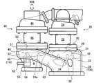
- FIG. 2 is a plan view (top view) showing the housing of the multistage turbocharger according to the present embodiment.
- FIG. 3 is a front view showing the turbine housing according to the present embodiment.
- FIG. 1 is a schematic configuration diagram of a supercharging system including a multistage supercharger according to the present embodiment.
- the supercharging system 10 of this embodiment is applied to, for example, the engine system 100 shown in FIG. Therefore, first, the engine system 100 will be described.
- the engine system 100 includes a supercharging system 10, an engine 101, an intercooler 102, a purification device 103, and an ECU (Engine Control Unit) 104.
- the engine system 100 is mounted on a vehicle, for example.
- the engine 101 is a power source of a vehicle on which the engine system 100 is mounted.
- the engine 101 is an internal combustion engine, and generates power by burning an air-fuel mixture of air compressed by the supercharging system 10 and fuel.
- the engine 101 burns the air-fuel mixture and supplies exhaust gas generated by the combustion to the supercharging system 10.
- the intercooler 102 cools the compressed air supplied from the supercharging system 10 to the engine 101.
- the inlet side of the intercooler 102 is connected to a first compressor (described later) 21 and a second compressor (described later) 41 of the supercharging system 10 described later, and the outlet side of the intercooler 102 is connected via an intake manifold 105 of the engine 101. It is connected to the supercharging system 10.
- the purification device 103 purifies the exhaust gas discharged from the supercharging system 10.
- the purification device 103 includes, for example, a filter that collects particulate matter, a catalyst that promotes an oxidation reaction or reduction reaction of harmful components, and the like.
- the ECU 104 controls the entire engine system 100.
- the ECU 105 determines an intake switching valve (described later) 60 and an exhaust switching valve (described later) in the supercharging system 10 according to the output of the engine 101 (for example, the rotational speed and the flow rate of exhaust gas expected from the rotational speed).
- 61 and a waste gate valve (described later) 62 are controlled and the opening degree thereof is controlled.
- a supercharging system 10 compresses air using the exhaust gas of the engine 101 and supplies the compressed air to the engine 101.
- a supercharging system 10 includes a first supercharger (primary supercharger, high-pressure supercharger) 20 and a second supercharger (secondary supercharger, low-pressure supercharger). 40, an intake switching valve 60, an exhaust switching valve 61, and a waste gate valve 62.
- the first supercharger 20 and the second supercharger 40 are arranged in series in the exhaust gas flow direction. That is, the supercharging system 10 of this embodiment employs a series type multistage supercharger.
- the first supercharger 20 is disposed upstream of the second supercharger 40 in the exhaust gas flow direction.
- the first supercharger 20 includes a first compressor (high pressure stage compressor) 21 and a first turbine (high pressure stage turbine) 22.
- the first supercharger 20 may include a variable nozzle unit (not shown) that adjusts the exhaust gas ejection speed toward the first turbine 22.
- the first compressor 21 includes a first compressor impeller 23 and a first compressor housing 24 that rotatably accommodates the first compressor impeller 23.
- the first turbine 22 includes a first turbine impeller 25 and a first turbine housing (first sub-housing) 26 that rotatably accommodates the first turbine impeller 25.
- the first shaft 27 connects the first compressor impeller 23 and the first turbine impeller 25 and is rotatably supported by this bearing (not shown).
- a bearing (not shown) is attached to the first bearing housing 28.
- the second supercharger 40 is disposed downstream of the first supercharger 20 in the exhaust gas flow direction, and has a larger capacity than the first supercharger 20.
- the second supercharger 40 includes a second compressor (low pressure stage compressor) 41 and a second turbine (low pressure stage turbine) 42.
- the second supercharger 40 may include a variable nozzle unit (not shown) that adjusts the exhaust gas ejection speed toward the second turbine 42.
- the second compressor 41 includes a second compressor impeller 43 and a second compressor housing 44 that rotatably accommodates the second compressor impeller 43.
- the second turbine 42 includes a second turbine impeller 45 and a second turbine housing (second sub-housing) 46 that rotatably accommodates the second turbine impeller 45.
- the second shaft 47 connects the second compressor impeller 43 and the second turbine impeller 45 and is rotatably supported by this bearing (not shown).
- a bearing (not shown) is attached to the second bearing housing 48.
- the first turbine housing 26 of the first turbine 22 and the second turbine housing 46 of the second turbine 42 are integrally formed as a single turbine housing TH (see FIG. 2). That is, the first turbine housing 26 and the second turbine housing 46 are connected to each other without a connection member such as a flange.
- the intake switching valve 60 is provided in a bypass flow path 63 that communicates the intake side and the discharge side of the first compressor 21 while bypassing the first compressor 21, and opens and closes the bypass flow path 63.
- the intake air switching valve 60 is closed when the first compressor 21 is driven. In this case, the compressed air discharged from the second compressor 41 flows into the first compressor 21 and is compressed, and is supplied to the intake side of the engine 101 via the intake manifold 105.
- the intake air switching valve 60 is opened when the first compressor 21 is not driven.
- the compressed air discharged from the second compressor 41 is supplied to the intake side of the engine 101 via the intake manifold 105 while bypassing the first compressor 21. That is, the intake air switching valve 60 allows the flow of compressed air from the second compressor 41 to the engine 101 via the bypass flow path 63.
- the intake air switching valve 60 is configured to prevent the backflow of compressed air from the engine 101 to the second compressor 41. That is, the intake air switching valve 60 also functions as a so-called check valve.
- the exhaust switching valve 61 is provided in a bypass passage 64 that communicates the intake side and the discharge side of the first turbine 22 while bypassing the first turbine 22, and opens and closes the bypass passage 64. While the exhaust gas switching valve 61 is closed, the exhaust gas discharged from the engine 101 passes through the first turbine impeller 25 of the first supercharger 20 and is then discharged from the first supercharger 20. As a result, the first turbine impeller 25 rotates, and the first compressor 21 performs air compression by this rotation.
- the exhaust gas switching valve 61 while the exhaust gas switching valve 61 is open, the exhaust gas discharged from the engine 101 passes through the bypass flow path 64 and is discharged from the first supercharger 20 and then supplied to the second supercharger 40. Is done. In other words, the exhaust gas bypasses the first turbine impeller 25 and is discharged from the first supercharger 20 and supplied to the second supercharger 40. That is, the exhaust gas switching valve 61 stops the compression of the air performed by the first compressor 21 by opening the bypass passage 64.
- the waste gate valve 62 is provided in the bypass passage 65 that communicates the intake side and the discharge side of the second turbine 42 while bypassing the second turbine 42, and opens and closes the bypass passage 65. While the waste gate valve 62 is open, a part of the exhaust gas passes through the bypass passage 65, is discharged from the second supercharger 40, and then flows into the purification device 103. In other words, a part of the exhaust gas is discharged from the second supercharger 40 by bypassing the second turbine impeller 45 and then flows into the purification device 103.
- the opening degree of the waste gate valve 62 is adjusted by the supercharging pressure of the ECU 105 or the second compressor 41.
- the opening degree of the waste gate valve 62 changes according to the supercharging pressure or the like required by the engine 101. That is, the opening degree of the waste gate valve 62 changes from fully open to fully closed. Thereby, the amount of exhaust gas flowing into the second turbine impeller 45 (that is, the rotational speeds of the second turbine impeller 45 and the second compressor impeller 43) can be adjusted.
- FIG. 2 is a plan view (top view) showing the housing of the multistage turbocharger according to the present embodiment.
- FIG. 3 is a front view showing the turbine housing according to the present embodiment.
- the housing of the first supercharger 20 includes a first turbine housing 26, a first compressor housing 24, and a first bearing housing 28.
- a first turbine housing 26 is connected to one end of the first bearing housing 28, and a first compressor housing is connected to the other end of the first bearing housing 28.
- the first compressor housing 24 is connected to the first turbine housing 26 via the first bearing housing 28.
- the housing of the second supercharger 40 includes a second turbine housing 46, a second compressor housing 44, and a second bearing housing 48.
- a second turbine housing 46 is connected to one end of the second bearing housing 48, and a first compressor housing is connected to the other end of the second bearing housing 48.
- the second compressor housing 44 is connected to the second turbine housing 46 via the second bearing housing 48.
- each housing of the 1st supercharger 20 and the 2nd supercharger 40 is formed by casting, for example.
- first turbine housing 26 and the second turbine housing 46 are integrally formed as a single turbine housing TH. That is, the first turbine housing 26 and the second turbine housing 46 are connected to each other without using a connecting member such as a flange, and constitute a turbine housing TH as a single structure.
- the first turbine housing 26 has a first turbine impeller accommodating chamber 29.
- the first turbine impeller accommodating chamber 29 includes an axisymmetric shape that matches the shape of the first turbine impeller 25 and accommodates the first turbine impeller 25.
- the first turbine impeller accommodating chamber 29 has an insertion port 30 for the first turbine impeller 25.
- the insertion port 30 is open to a flange (rib) 31 facing the first bearing housing 28.
- the first turbine housing 26 includes a first scroll passage 32, a first intake passage 33, and a first exhaust passage 34.
- the first scroll flow path 32 is provided on the outer periphery of the first turbine impeller accommodating chamber 29 and communicates with the first scroll flow path 32.
- the first scroll flow path 32 extends spirally in the circumferential direction of the first turbine impeller 25 with reference to the symmetry axis of the first turbine impeller accommodating chamber 29 (in other words, the rotation center axis of the first turbine impeller). . Further, the cross-sectional area of the first scroll passage 32 gradually decreases from the winding start side along the flow direction of the exhaust gas.
- the first intake passage 33 is connected to the end portion on the winding start side of the first scroll passage 32 (that is, the portion having the largest cross-sectional area).
- the first intake passage 33 opens to a flange (rib) 35 of the first turbine housing 26 and is connected to the exhaust manifold 106 of the engine 101.
- the flange 35 is located on the opposite side of the flange 31 with the first turbine impeller accommodating chamber 29 interposed therebetween.
- the first exhaust path 34 (one end side of the first exhaust path 34) communicates with the first turbine impeller accommodating chamber 29 so as to open toward the rear edge (trailing edge) of the first turbine impeller 25. .
- the first exhaust passage 34 (the other end side of the first exhaust passage 34) communicates with the second intake passage 53 of the second supercharger 40 inside the first turbine housing 26.
- the second turbine housing 46 has a second turbine impeller accommodating chamber 49.
- the second turbine impeller accommodating chamber 49 includes an axisymmetric shape that matches the shape of the second turbine impeller 45 and accommodates the second turbine impeller 45.
- the second turbine impeller accommodating chamber 49 has an insertion port 50 for the second turbine impeller 45.
- the insertion port 50 is open to a flange (rib) 51 facing the second bearing housing 48.
- the supercharging system 10 of the present embodiment employs a series-type multistage supercharger. Therefore, the first turbine impeller accommodating chamber 29 of the first turbine housing 26 and the second turbine impeller accommodating chamber 49 of the second turbine housing 46 are arranged in series in the exhaust gas flow direction in the turbine housing TH.
- the second turbine housing 46 includes a second scroll passage 52, a second intake passage 53, and a second exhaust passage 54.
- the second scroll passage 52 is provided on the outer periphery of the second turbine impeller housing chamber 49 and communicates with the second scroll passage 52.
- the second scroll passage 52 extends spirally in the circumferential direction of the second turbine impeller 45 with reference to the axis of symmetry of the second turbine impeller accommodating chamber 49 (in other words, the rotation center axis of the second turbine impeller). . Further, the cross-sectional area of the second scroll channel 52 gradually decreases along the flow direction of the exhaust gas from the winding start side.
- the second intake passage 53 is connected to the end of the second scroll passage 52 on the winding start side (that is, the portion having the largest cross-sectional area).
- the second intake passage 53 extends from the second scroll passage 52 to the flange 35 of the first turbine housing 26 and opens at the flange 35. That is, the first intake passage 33 and the second intake passage 53 are open to the same flange 35.
- the second intake passage 53 is connected to the exhaust manifold 106 of the engine 101 via the exhaust switching valve 61.
- the second intake passage 53 is formed in a cylindrical shape, and its cross-sectional area (opening area) gradually increases from the second scroll passage 52 toward the flange 35.
- the second intake passage 53 is not structurally divided between the second scroll passage 52 and the flange 35. That is, the second intake passage 53 does not have a joint structure (for example, a flange) for connecting the first turbine housing 26 and the second turbine housing 46.
- the second exhaust passage 54 (one end side of the second exhaust passage 54) communicates with the second turbine impeller accommodating chamber 49 so as to open toward the rear edge (trailing edge) of the second turbine impeller 45. . Further, the second exhaust passage 54 (the other end side of the second exhaust passage 54) opens to a flange (rib) 55 of the second turbine housing 46. The flange 55 is located on the opposite side of the flange 51 with the second turbine impeller accommodating chamber 49 interposed therebetween.
- the waste gate valve 62 is installed in the second turbine housing 46.
- the bypass passage 65 is formed in the inner wall 53 a of the second intake passage 53 and communicates with the second exhaust passage 54.
- the waste gate valve 62 opens and closes the second intake path 53 side of the second exhaust path 54.
- first turbine housing (first sub housing) 26 and the second turbine housing (second sub housing) 46 are integrally formed as a single turbine housing TH. That is, the joint structure (for example, flange) for connecting each housing becomes unnecessary. Therefore, it is possible to reduce the size of the multistage turbocharger while ensuring the expansion of the operating range.
- the piping constituting the second intake passage 53 connects the first turbine housing 26 and the second turbine housing 46.
- the inlet side of the second intake passage 53 of the second supercharger 40 is integrated with the first turbine housing 26 of the first supercharger 20.
- the first turbine housing 26 and the second turbine housing 46 may be connected to each other via the second intake passage 53 and may be separated from each other.
- the first turbine housing 26 and the second turbine housing 46 may be provided via a gap except for the second intake passage 53.
- the second intake passage 53 functions as an elastic body, and the mutual influence (for example, mixing of stress) of the thermal deformation of the first turbine housing 26 and the thermal deformation of the second turbine housing 46 accompanying the circulation of the exhaust gas. Is suppressed (insulated) as much as possible. Moreover, since the mutual heat flow between the 1st turbine housing 26 and the 2nd turbine housing 46 is suppressed, the heat loss by such a heat flow can also be suppressed.
- the thickness of the piping constituting the second intake passage 53 may be set to a value as small as possible as long as the connection between the first turbine housing 26 and the second turbine housing 46 and the prevention of exhaust gas leakage can be maintained. Since the heat capacity of the pipe decreases as the pipe thickness decreases, at least heat loss of the exhaust gas flowing through the second intake passage 53 can be suppressed.
- the flange 35 and the flange 55 may be located in parallel to each other. That is, the first intake passage 33, the second intake passage 53, and the second exhaust passage 54 may be open in the same direction.
- “same” here means “substantially identical”, in other words, “substantially identical”, and these do not require opening in exactly the same direction. In this case, since the ratio that these related members are located in the direction in which each flow path opens increases, workability is improved.
- the second intake passage 53 may be inclined with respect to the surface R on which the second scroll passage 52 extends.
- the surface R is, for example, a plane orthogonal to the symmetry axis of the second turbine impeller accommodating chamber 49. Since it can be avoided that the flow direction of the exhaust gas flowing through the second scroll passage 52 via the second intake passage 53 is abruptly deflected, reduction in turbine efficiency can be suppressed.
- the first compressor housing 24 and the second compressor housing 44 may be formed separately. In this case, it is desirable that the pipe connecting the first compressor housing 24 and the second compressor housing 44 has a structure that gives flexibility. As described above, the first turbine housing 26 and the second turbine housing 46 are thermally deformed as the exhaust gas flows. By forming the first compressor housing 24 and the second compressor housing 44 individually, it is possible to suppress the generation of new stress due to the deformation of the turbine housings having different degrees.
Abstract
多段過給機は、第1タービンインペラ収容室(29)を有する第1サブハウジング(26)、及び、第1タービンインペラ収容室(29)と直列に配列する第2タービンインペラ収容室(49)を有する第2サブハウジング(46)を含むタービンハウジング(TH)と、タービンハウジング(TH)に第1ベアリングハウジング(28)を介して連結する第1コンプレッサハウジング(24)と、タービンハウジング(TH)に第2ベアリングハウジング(48)を介して連結する第2コンプレッサハウジング(44)とを備える。第1サブハウジング(26)及び第2サブハウジング(46)は一体形成されている。
Description
本開示は、直列に配列した複数の過給機を備える多段過給機に関する。
多段過給機は複数の過給機を備えた過給装置であり、過給機を1台だけを備えた過給装置と比べ、より広い作動範囲を確保できることが知られている。種々の多段過給機のうち、排気ガスの流れ方向に2台の過給機が直列に配列したものは、直列型多段過給機やシリーズシーケンシャルツインターボなどと呼ばれている。直列型多段過給機では、エンジンの低速回転域において高圧側の(初段の)過給機が作動し、エンジンの高速回転域において低圧側の(次段の)過給機が作動する。このような作動によって作動範囲が拡大される。
特許文献1は上述の直列型多段過給機を開示している。特許文献1の多段過給機は、各過給機のコンプレッサケーシング(コンプレッサハウジング)に形成されたバイパス流路を有している。多段過給機に吸引された空気はバイパス流路を流れ、コンプレッサインペラをバイパスする。このような構造の導入によって、コンプレッサケーシングとは別にバイパス流路を用意する必要がなくなり、且つ、エンジン周りの配管が複雑化することが抑制される。
特許文献1がエンジン周りの配管の複雑化を憂慮しているように、エンジンルーム内の部品点数の増加は、車両の軽量化や燃費の向上を阻み、組立時や修理時の作業性を低下させる恒久的な課題である。これは多段過給機に対しても同様である。
本開示は、このような事情に鑑みてなされたものであり、作動範囲の拡大を確保しつつ、小型化が可能な直列型多段過給機の提供を目的とする。
本開示の一態様は多段過給機であって、第1タービンインペラ収容室を有する第1サブハウジング、及び、前記第1タービンインペラ収容室と直列に配列する第2タービンインペラ収容室を有する第2サブハウジングを含むタービンハウジングと、前記タービンハウジングに第1ベアリングハウジングを介して連結する第1コンプレッサハウジングと、前記タービンハウジングに第2ベアリングハウジングを介して連結する第2コンプレッサハウジングとを備え、前記第1サブハウジングと前記第2サブハウジングは一体形成されていることを要旨とする。
前記タービンハウジングは、第1タービンインペラ収容室に連通する第1吸気路及び第1排気路と、第2タービンインペラ収容室に連通する第2吸気路及び第2排気路とを有してもよい。前記第1吸気路、前記第2吸気路及び前記第2排気路は略同一方向に向けて開口していてもよい。
前記第1サブハウジング及び記第2サブハウジングは、前記第2吸気路を介して互いに接続していると共に、互いに離隔していてもよい。
前記第2吸気路は、前記第2タービンインペラ収容室のスクロール流路が延伸する面に対して傾斜していてもよい。
前記第1コンプレッサハウジング及び前記第2コンプレッサハウジングは個別に形成されていてもよい。
本開示によれば、作動範囲の拡大を確保しつつ、小型化が可能な直列型多段過給機を提供できる。
以下、本開示の実施形態に係る多段過給機について添付図面に基づいて説明する。なお、各図において共通する部分には同一の符号を付し、重複する説明を省略する。図1は、本実施形態に係る多段過給機を備える過給システムの概略構成図である。
本実施形態の過給システム10は、例えば、図1に示すエンジンシステム100に適用される。従って、まず、エンジンシステム100について説明する。エンジンシステム100は、過給システム10と、エンジン101と、インタークーラ102と、浄化装置103と、ECU(Engine Control Unit)104とを備えている。エンジンシステム100は例えば車両に搭載される。
エンジン101は、エンジンシステム100を搭載した車両の動力源である。エンジン101は内燃機関であり、過給システム10によって圧縮された空気と、燃料との混合気を燃焼して動力を生成する。また、エンジン101は混合気を燃焼し、燃焼によって発生した排気ガスを過給システム10に供給する。
インタークーラ102は、過給システム10からエンジン101に供給される圧縮空気を冷却する。インタークーラ102の入口側は後述する過給システム10の第1コンプレッサ(後述)21及び第2コンプレッサ(後述)41に接続し、インタークーラ102の出口側は、エンジン101の吸気マニホールド105を介して過給システム10とに接続している。
浄化装置103は、過給システム10から排出された排気ガスを浄化する。浄化装置103は、例えば、粒子状物質を捕集するフィルタや、有害成分の酸化反応あるいは還元反応を促進する触媒などで構成される。
ECU104は、エンジンシステム100の全体を制御する。例えば、ECU105は、エンジン101の出力(例えば、回転数や、回転数から見込まれる排気ガスの流量)に応じて、過給システム10内の吸気切換え弁(後述)60、排気切換え弁(後述)61及びウェイストゲートバルブ(後述)62の開閉や、その開度を制御する。
次に過給システム10について説明する。
過給システム10は、エンジン101の排気ガスを利用して空気を圧縮し、その圧縮空気をエンジン101に供給する。図1に示すように、過給システム10は、第1過給機(プライマリ過給機、高圧段過給機)20と、第2過給機(セカンダリ過給機、低圧段過給機)40と、吸気切換え弁60と、排気切換え弁61と、ウェイストゲートバルブ62とを備えている。第1過給機20と第2過給機40は、排気ガスの流れ方向に直列に配列している。即ち、本実施形態の過給システム10は直列型多段過給機を採用している。
過給システム10は、エンジン101の排気ガスを利用して空気を圧縮し、その圧縮空気をエンジン101に供給する。図1に示すように、過給システム10は、第1過給機(プライマリ過給機、高圧段過給機)20と、第2過給機(セカンダリ過給機、低圧段過給機)40と、吸気切換え弁60と、排気切換え弁61と、ウェイストゲートバルブ62とを備えている。第1過給機20と第2過給機40は、排気ガスの流れ方向に直列に配列している。即ち、本実施形態の過給システム10は直列型多段過給機を採用している。
第1過給機20は、排気ガスの流れ方向において第2過給機40よりも上流側に配置されている。第1過給機20は、第1コンプレッサ(高圧段コンプレッサ)21と、第1タービン(高圧段タービン)22とを備えている。なお、第1過給機20は、第1タービン22に向かう排気ガスの噴出速度を調整する可変ノズルユニット(図示せず)を備えてもよい。
第1コンプレッサ21は、第1コンプレッサインペラ23と、第1コンプレッサインペラ23を回転可能に収容する第1コンプレッサハウジング24とを備えている。第1タービン22は、第1タービンインペラ25と、第1タービンインペラ25を回転可能に収容する第1タービンハウジング(第1サブハウジング)26とを備えている。第1シャフト27は、第1コンプレッサインペラ23と第1タービンインペラ25とを連結し、このベアリング(図示せず)によって回転可能に支持される。ベアリング(図示せず)は、第1ベアリングハウジング28に取り付けられている。第1タービンインペラ25が排気ガスの流通によって回転すると第1コンプレッサインペラ23も回転する。この第1コンプレッサインペラ23の回転によって、圧縮空気が生成される。
第2過給機40は、排気ガスの流れ方向において第1過給機20よりも下流側に配置されており、第1過給機20よりも大きい容量を有する。第2過給機40は、第2コンプレッサ(低圧段コンプレッサ)41と、第2タービン(低圧段タービン)42とを備えている。なお、第2過給機40は、第2タービン42に向かう排気ガスの噴出速度を調整する可変ノズルユニット(図示せず)を備えてもよい。
第2コンプレッサ41は、第2コンプレッサインペラ43と、第2コンプレッサインペラ43を回転可能に収容する第2コンプレッサハウジング44とを備えている。第2タービン42は、第2タービンインペラ45と、第2タービンインペラ45を回転可能に収容する第2タービンハウジング(第2サブハウジング)46とを備えている。第2シャフト47は、第2コンプレッサインペラ43と第2タービンインペラ45とを連結し、このベアリング(図示せず)によって回転可能に支持される。ベアリング(図示せず)は、第2ベアリングハウジング48に取り付けられている。第2タービンインペラ45が排気ガスの流通によって回転すると第2コンプレッサインペラ43も回転する。この第2コンプレッサインペラ43の回転によって、圧縮空気が生成される。
なお、第1タービン22の第1タービンハウジング26と、第2タービン42の第2タービンハウジング46は、単一のタービンハウジングTHとして一体形成されている(図2参照)。即ち、第1タービンハウジング26と第2タービンハウジング46は、フランジなどの接続部材を介さずに互いに接続している。
吸気切換え弁60は、第1コンプレッサ21を迂回しながら、第1コンプレッサ21の吸気側と排出側を連通するバイパス流路63に設けられ、バイパス流路63を開閉する。吸気切換え弁60は、第1コンプレッサ21が駆動されている場合に閉じる。この場合、第2コンプレッサ41から排出された圧縮空気は、第1コンプレッサ21に流入して圧縮され、吸気マニホールド105を介してエンジン101の吸気側に供給される。
一方、吸気切換え弁60は、第1コンプレッサ21が駆動されていない場合に開く。この場合、第2コンプレッサ41から排出された圧縮空気は、第1コンプレッサ21をバイパスしながら、吸気マニホールド105を介してエンジン101の吸気側に供給される。即ち、吸気切換え弁60は、バイパス流路63を経由した第2コンプレッサ41からエンジン101への圧縮空気の流れを許容する。なお、吸気切換え弁60は、エンジン101から第2コンプレッサ41への圧縮空気の逆流を防止するように構成されている。つまり、吸気切換え弁60は所謂逆止弁としても機能する。
排気切換え弁61は、第1タービン22を迂回しながら、第1タービン22の吸気側と排出側を連通するバイパス流路64に設けられ、バイパス流路64を開閉する。排気切換え弁61が閉じている間、エンジン101から排出される排気ガスは、第1過給機20の第1タービンインペラ25を通過し、その後、第1過給機20から排出される。その結果、第1タービンインペラ25は回転し、この回転によって第1コンプレッサ21は空気の圧縮を実行する。
一方、排気切換え弁61が開いている間、エンジン101から排出される排気ガスは、バイパス流路64を通過し、第1過給機20から排出され、その後、第2過給機40に供給される。換言すれば、排気ガスは、第1タービンインペラ25をバイパスして第1過給機20から排出され、第2過給機40に供給される。つまり、排気切換え弁61は、バイパス流路64を開くことによって、第1コンプレッサ21が実行する空気の圧縮を停止する。
ウェイストゲートバルブ62は、第2タービン42を迂回しながら、第2タービン42の吸気側と排出側を連通するバイパス流路65に設けられ、バイパス流路65を開閉する。ウェイストゲートバルブ62が開いている間、上記排気ガスの一部は、バイパス流路65を通過し、第2過給機40から排出され、その後、浄化装置103に流入する。換言すれば、上記排気ガスの一部は、第2タービンインペラ45をバイパスして第2過給機40から排出され、その後、浄化装置103に流入する。なお、ウェイストゲートバルブ62の開度は、ECU105または第2コンプレッサ41の過給圧によって調節される。
一方、ウェイストゲートバルブ62が閉じている間、第1過給機20から排出された或いはバイパス流路64を介して排出された排気ガスは、第2過給機40の第2タービンインペラ45を通過し、その後、第2過給機40から排出される。その結果、第2タービンインペラ45は回転し、この回転によって第2コンプレッサ41は空気の圧縮を実行する。
なお、ウェイストゲートバルブ62の開度は、エンジン101が要求する過給圧等に応じて変化する。即ち、ウェイストゲートバルブ62の開度は、全開から全閉まで変化する。これにより、第2タービンインペラ45に流入する排気ガスの量(即ち、第2タービンインペラ45及び第2コンプレッサインペラ43の回転数)を調整できる。
次に、本実施形態に係る多段過給機のハウジングについて説明する。図2は、本実施形態に係る多段過給機のハウジングを示す平面図(上面図)である。図3は、本実施形態に係るタービンハウジングを示す正面図である。
図2に示すように、第1過給機20のハウジングは、第1タービンハウジング26と、第1コンプレッサハウジング24と、第1ベアリングハウジング28とによって構成される。第1ベアリングハウジング28の一端には第1タービンハウジング26が接続し、第1ベアリングハウジング28の他端には第1コンプレッサハウジングが接続する。換言すれば、第1コンプレッサハウジング24は、第1ベアリングハウジング28を介して第1タービンハウジング26に連結している。
同様に、第2過給機40のハウジングは、第2タービンハウジング46と、第2コンプレッサハウジング44と、第2ベアリングハウジング48とによって構成される。第2ベアリングハウジング48の一端には第2タービンハウジング46が接続し、第2ベアリングハウジング48の他端には第1コンプレッサハウジングが接続する。換言すれば、第2コンプレッサハウジング44は、第2ベアリングハウジング48を介して第2タービンハウジング46に連結している。
なお、第1過給機20及び第2過給機40の各ハウジングは、例えば鋳造によって形成される。
上述の通り、第1タービンハウジング26及び第2タービンハウジング46は、単一のタービンハウジングTHとして一体形成されている。即ち、第1タービンハウジング26と第2タービンハウジング46は、フランジなどの接続部材を介さずに互いに接続し、単一構造体としてのタービンハウジングTHを構成する。
図3に示すように、第1タービンハウジング26は、第1タービンインペラ収容室29を有する。第1タービンインペラ収容室29は第1タービンインペラ25の形状に合わせた軸対称な形状を含み、第1タービンインペラ25を収容する。第1タービンインペラ収容室29は、第1タービンインペラ25の挿入口30を有する。挿入口30は、第1ベアリングハウジング28に面したフランジ(リブ)31に開口している。
第1タービンハウジング26は、第1スクロール流路32と、第1吸気路33と、第1排気路34とを有する。第1スクロール流路32は、第1タービンインペラ収容室29の外周に設けられ、第1スクロール流路32に連通している。第1スクロール流路32は、第1タービンインペラ収容室29の対称軸(換言すれば、第1タービンインペラの回転中心軸)を基準として、第1タービンインペラ25の周方向に渦巻き状に延伸する。また、第1スクロール流路32の断面積は、その巻き始め側から排気ガスの流れ方向に沿って漸次減少する。
第1吸気路33は、第1スクロール流路32の巻き始め側の端部(即ち、断面積が最大となる部分)に接続している。また、第1吸気路33は、第1タービンハウジング26のフランジ(リブ)35に開口し、エンジン101の排気マニホールド106と接続する。なお、フランジ35は、第1タービンインペラ収容室29を挟んで、フランジ31と反対側に位置する。
第1排気路34(第1排気路34の一端側)は、第1タービンインペラ25の後縁(トレーリングエッジ)に向けて開口するように、第1タービンインペラ収容室29に連通している。また、第1排気路34(第1排気路34の他端側)は、第1タービンハウジング26の内部で、第2過給機40の第2吸気路53に連通している。
第2タービンハウジング46は、第2タービンインペラ収容室49を有する。第2タービンインペラ収容室49は第2タービンインペラ45の形状に合わせた軸対称な形状を含み、第2タービンインペラ45を収容する。第2タービンインペラ収容室49は、第2タービンインペラ45の挿入口50を有する。挿入口50は、第2ベアリングハウジング48に面したフランジ(リブ)51に開口している。
上述の通り、本実施形態の過給システム10は直列型多段過給機を採用している。従って、第1タービンハウジング26の第1タービンインペラ収容室29と、第2タービンハウジング46の第2タービンインペラ収容室49は、タービンハウジングTHにおいて排気ガスの流れ方向に直列に配列している。
第2タービンハウジング46は、第2スクロール流路52と、第2吸気路53と、第2排気路54とを有する。第2スクロール流路52は、第2タービンインペラ収容室49の外周に設けられ、第2スクロール流路52に連通している。第2スクロール流路52は、第2タービンインペラ収容室49の対称軸(換言すれば、第2タービンインペラの回転中心軸)を基準として、第2タービンインペラ45の周方向に渦巻き状に延伸する。また、第2スクロール流路52の断面積は、その巻き始め側から排気ガスの流れ方向に沿って漸次減少する。
第2吸気路53は、第2スクロール流路52の巻き始め側の端部(即ち、断面積が最大となる部分)に接続している。第2吸気路53は、第2スクロール流路52から第1タービンハウジング26のフランジ35まで延伸し、フランジ35にて開口している。つまり、第1吸気路33と第2吸気路53は、同一のフランジ35に開口している。第2吸気路53は、排気切換え弁61を介してエンジン101の排気マニホールド106と接続する。
第2吸気路53は筒状に形成され、その断面積(開口面積)は、第2スクロール流路52からフランジ35に向かうに連れて漸次増加する。第2吸気路53は、第2スクロール流路52からフランジ35までの間で構造的に分断されていない。つまり、第2吸気路53は、第1タービンハウジング26と第2タービンハウジング46を接続するための継手構造(例えばフランジ)を持たない。
第2排気路54(第2排気路54の一端側)は、第2タービンインペラ45の後縁(トレーリングエッジ)に向けて開口するように、第2タービンインペラ収容室49に連通している。また、第2排気路54(第2排気路54の他端側)は、第2タービンハウジング46のフランジ(リブ)55に開口している。フランジ55は、第2タービンインペラ収容室49を挟んで、フランジ51と反対側に位置する。
ウェイストゲートバルブ62は、第2タービンハウジング46に設置される。バイパス流路65は、第2吸気路53の内壁53aに形成され、第2排気路54に連通する。ウェイストゲートバルブ62は、第2排気路54の第2吸気路53側を開閉する。
本実施形態では、第1タービンハウジング(第1サブハウジング)26と第2タービンハウジング(第2サブハウジング)46が、単一のタービンハウジングTHとして一体形成されている。つまり、各ハウジングを接続するための継手構造(例えばフランジ)が不要になる。従って、作動範囲の拡大を確保しつつ、多段過給機を小型化することができる。
なお、図2及び図3に示すように、第2吸気路53を構成する配管は、第1タービンハウジング26と第2タービンハウジング46とを連結している。換言すれば、第2過給機40の第2吸気路53の入口側が、第1過給機20の第1タービンハウジング26と一体化されている。このように、第1タービンハウジング26と第2タービンハウジング46は、第2吸気路53を介して互いに接続され、互いに離隔していてもよい。換言すれば、第1タービンハウジング26と第2タービンハウジング46は、第2吸気路53を除き、空隙を介して設けられていてもよい。この場合、第2吸気路53は弾性体として機能し、排気ガスの流通に伴う、第1タービンハウジング26の熱変形と、第2タービンハウジング46の熱変形の互いの影響(例えば応力の混合)を極力抑制(絶縁)する。また、第1タービンハウジング26と第2タービンハウジング46の間の互いの熱流動が抑制されるので、このような熱流動による熱損失も抑制できる。
また、第2吸気路53を構成する配管の厚みは、第1タービンハウジング26と第2タービンハウジング46の連結や排気ガスの漏洩防止を維持できる限り、極力小さな値に設定されてもよい。配管の厚みが小さいほど配管の熱容量が減少するため、少なくとも第2吸気路53を流れる排気ガスの熱損失を抑制できる。
図2及び図3に示すように、フランジ35とフランジ55は互いに平行に位置していてもよい。即ち、第1吸気路33、第2吸気路53及び第2排気路54は同一方向に向けて開口していてもよい。ただし、ここで言う「同一」とは「略同一」、換言すれば「実質的に同一」という意味であり、これらが厳密に同一方向に開口することを要求しない。この場合、各流路が開口する方向にこれらの関連部材が位置する割合が増えるため、作業性が向上する。
図2に示すように、第2吸気路53は、第2スクロール流路52が延伸する面Rに対して傾斜していてもよい。ここで、面Rは、例えば、第2タービンインペラ収容室49の対称軸に直交する平面である。第2吸気路53を経由して第2スクロール流路52に流れる排気ガスの流れ方向が急激に偏向されることを回避できるため、タービン効率の低減を抑制できる。
図2に示すように、第1コンプレッサハウジング24及び第2コンプレッサハウジング44は個別に形成されていてもよい。この場合、第1コンプレッサハウジング24と第2コンプレッサハウジング44を接続する配管は、可撓性を与える構造を有するものが望ましい。上述の通り、排気ガスの流通に伴って、第1タービンハウジング26及び第2タービンハウジング46は熱変形する。第1コンプレッサハウジング24及び第2コンプレッサハウジング44を個別に形成することで、程度の異なる各タービンハウジングの変形に起因した新たな応力の発生を抑制できる。
なお、本開示は上述の実施形態に限定されず、特許請求の範囲の記載によって示され、さらに特許請求の範囲の記載と均等の意味および範囲内でのすべての変更を含む。
Claims (4)
- 第1タービンインペラ収容室を有する第1サブハウジング、及び、前記第1タービンインペラ収容室と直列に配列する第2タービンインペラ収容室を有する第2サブハウジングを含むタービンハウジングと、
前記タービンハウジングに第1ベアリングハウジングを介して連結する第1コンプレッサハウジングと、
前記タービンハウジングに第2ベアリングハウジングを介して連結する第2コンプレッサハウジングと
を備え、
前記第1サブハウジングと前記第2サブハウジングは一体形成されており、
前記タービンハウジングは、
前記第1タービンインペラ収容室に連通する第1吸気路及び第1排気路と、
前記第2タービンインペラ収容室に連通する第2吸気路及び第2排気路と
を有し、
前記第1吸気路、前記第2吸気路及び前記第2排気路は略同一方向に向けて開口している、
多段過給機。 - 前記第1サブハウジング及び前記第2サブハウジングは、前記第2吸気路を介して互いに接続していると共に、互いに離隔している
請求項1に記載の多段過給機。 - 前記第2吸気路は、前記第2タービンインペラ収容室のスクロール流路が延伸する面に対して傾斜している
請求項2に記載の多段過給機。 - 前記第1コンプレッサハウジング及び前記第2コンプレッサハウジングは個別に形成されている、
請求項1~3の何れか一項に記載の多段過給機。
Priority Applications (4)
| Application Number | Priority Date | Filing Date | Title |
|---|---|---|---|
| CN201880030166.4A CN110603376B (zh) | 2017-06-13 | 2018-04-03 | 多级增压器 |
| JP2019525120A JP6780778B2 (ja) | 2017-06-13 | 2018-04-03 | 多段過給機 |
| DE112018002996.4T DE112018002996T5 (de) | 2017-06-13 | 2018-04-03 | Mehrstufiger Turbolader |
| US16/674,623 US11078830B2 (en) | 2017-06-13 | 2019-11-05 | Multi-stage turbocharger |
Applications Claiming Priority (2)
| Application Number | Priority Date | Filing Date | Title |
|---|---|---|---|
| JP2017115831 | 2017-06-13 | ||
| JP2017-115831 | 2017-06-13 |
Related Child Applications (1)
| Application Number | Title | Priority Date | Filing Date |
|---|---|---|---|
| US16/674,623 Continuation US11078830B2 (en) | 2017-06-13 | 2019-11-05 | Multi-stage turbocharger |
Publications (1)
| Publication Number | Publication Date |
|---|---|
| WO2018230108A1 true WO2018230108A1 (ja) | 2018-12-20 |
Family
ID=64659172
Family Applications (1)
| Application Number | Title | Priority Date | Filing Date |
|---|---|---|---|
| PCT/JP2018/014282 WO2018230108A1 (ja) | 2017-06-13 | 2018-04-03 | 多段過給機 |
Country Status (5)
| Country | Link |
|---|---|
| US (1) | US11078830B2 (ja) |
| JP (1) | JP6780778B2 (ja) |
| CN (1) | CN110603376B (ja) |
| DE (1) | DE112018002996T5 (ja) |
| WO (1) | WO2018230108A1 (ja) |
Cited By (1)
| Publication number | Priority date | Publication date | Assignee | Title |
|---|---|---|---|---|
| DE102020100386A1 (de) * | 2020-01-10 | 2021-07-15 | Bayerische Motoren Werke Aktiengesellschaft | Gehäusebauteil für ein Turbinengehäuse eines Abgasturboladers |
Citations (6)
| Publication number | Priority date | Publication date | Assignee | Title |
|---|---|---|---|---|
| JP2003531996A (ja) * | 2000-04-20 | 2003-10-28 | ボーグワーナー・インコーポレーテッド | 内燃機関用ターボチャージャ装置 |
| JP2004092646A (ja) * | 2002-08-30 | 2004-03-25 | Borgwarner Inc | 内燃機関用過給装置 |
| WO2010122668A1 (ja) * | 2009-04-24 | 2010-10-28 | トヨタ自動車 株式会社 | 内燃機関の過給機システム |
| JP2010255565A (ja) * | 2009-04-27 | 2010-11-11 | Toyota Motor Corp | 内燃機関 |
| JP2010261362A (ja) * | 2009-05-07 | 2010-11-18 | Toyota Motor Corp | エンジンの過給装置 |
| US20110020108A1 (en) * | 2006-04-05 | 2011-01-27 | Gm Global Technology Operations, Inc. | Two-stage turbo-charger engine system |
Family Cites Families (25)
| Publication number | Priority date | Publication date | Assignee | Title |
|---|---|---|---|---|
| JPS6040728A (ja) * | 1983-08-11 | 1985-03-04 | Fuji Heavy Ind Ltd | 過給機付エンジン |
| DE19822874A1 (de) | 1998-05-22 | 1999-11-25 | Man Nutzfahrzeuge Ag | Aufladesystem für Brennkraftmaschinen |
| JP4479502B2 (ja) * | 2004-12-28 | 2010-06-09 | トヨタ自動車株式会社 | 内燃機関用多段過給システム及びその制御方法 |
| IL170165A (en) * | 2005-08-08 | 2010-12-30 | Haim Rom | Wankel and similar rotary engines |
| DE102005039756A1 (de) * | 2005-08-23 | 2007-03-01 | Robert Bosch Gmbh | Aufladeeinrichtung mit zweistufiger Niederdruckturbine |
| JP4495120B2 (ja) * | 2006-08-10 | 2010-06-30 | 三菱重工業株式会社 | 多段過給式排気ターボ過給機 |
| GB0717212D0 (en) * | 2007-09-05 | 2007-10-17 | Cummins Turbo Tech Ltd | Multi-stage turbocharger system |
| JP4875586B2 (ja) * | 2007-10-12 | 2012-02-15 | 三菱重工業株式会社 | 2段過給式排気ターボ過給機 |
| US8206133B2 (en) * | 2008-08-12 | 2012-06-26 | GM Global Technology Operations LLC | Turbocharger housing with integral inlet and outlet openings |
| GB2464500B (en) * | 2008-10-17 | 2013-02-20 | Cummins Turbo Tech Ltd | An internal combustion engine with exhaust gas recirculation |
| US8266906B2 (en) * | 2009-03-11 | 2012-09-18 | GM Global Technology Operations LLC | Asymmetric split-inlet turbine housing |
| JP2010281282A (ja) * | 2009-06-05 | 2010-12-16 | Toyota Motor Corp | 過給装置及びこれを備える内燃機関 |
| US8863514B2 (en) * | 2009-06-29 | 2014-10-21 | Borgwarner Inc. | Multi-stage turbocharger arrangement |
| JP2011085043A (ja) * | 2009-10-14 | 2011-04-28 | Ihi Corp | ターボチャージャ及び過給装置 |
| GB2475534B (en) * | 2009-11-21 | 2014-11-12 | Cummins Turbo Tech Ltd | Sequential two-stage turbocharger system |
| JP2011174425A (ja) * | 2010-02-25 | 2011-09-08 | Honda Motor Co Ltd | 内燃機関の多段過給装置 |
| JP5471899B2 (ja) * | 2010-06-30 | 2014-04-16 | マツダ株式会社 | 車両用エンジンのターボ過給機の潤滑装置 |
| JP5874161B2 (ja) * | 2010-10-28 | 2016-03-02 | いすゞ自動車株式会社 | ターボ過給システム |
| JP5879685B2 (ja) * | 2010-12-28 | 2016-03-08 | いすゞ自動車株式会社 | 多段過給装置 |
| DE112012000464T5 (de) * | 2011-03-04 | 2013-10-24 | Borgwarner Inc. | Mehrstufige Turboladeranordnung |
| GB2500192B (en) * | 2012-03-12 | 2015-11-18 | Jaguar Land Rover Ltd | Compact Multi-Stage Turbo Pump |
| CN102606285A (zh) * | 2012-04-07 | 2012-07-25 | 潍坊富源增压器有限公司 | 两级增压的涡轮增压器 |
| CN103615305B (zh) * | 2013-11-29 | 2016-01-20 | 长城汽车股份有限公司 | 一种涡轮增压器 |
| US9441531B2 (en) * | 2014-01-02 | 2016-09-13 | Caterpillar Inc. | Diverter valve for charge air system |
| GB2533351A (en) * | 2014-12-17 | 2016-06-22 | Gm Global Tech Operations Inc | Internal combustion engine having a two stage turbocharger |
-
2018
- 2018-04-03 DE DE112018002996.4T patent/DE112018002996T5/de active Pending
- 2018-04-03 JP JP2019525120A patent/JP6780778B2/ja active Active
- 2018-04-03 CN CN201880030166.4A patent/CN110603376B/zh active Active
- 2018-04-03 WO PCT/JP2018/014282 patent/WO2018230108A1/ja active Application Filing
-
2019
- 2019-11-05 US US16/674,623 patent/US11078830B2/en active Active
Patent Citations (6)
| Publication number | Priority date | Publication date | Assignee | Title |
|---|---|---|---|---|
| JP2003531996A (ja) * | 2000-04-20 | 2003-10-28 | ボーグワーナー・インコーポレーテッド | 内燃機関用ターボチャージャ装置 |
| JP2004092646A (ja) * | 2002-08-30 | 2004-03-25 | Borgwarner Inc | 内燃機関用過給装置 |
| US20110020108A1 (en) * | 2006-04-05 | 2011-01-27 | Gm Global Technology Operations, Inc. | Two-stage turbo-charger engine system |
| WO2010122668A1 (ja) * | 2009-04-24 | 2010-10-28 | トヨタ自動車 株式会社 | 内燃機関の過給機システム |
| JP2010255565A (ja) * | 2009-04-27 | 2010-11-11 | Toyota Motor Corp | 内燃機関 |
| JP2010261362A (ja) * | 2009-05-07 | 2010-11-18 | Toyota Motor Corp | エンジンの過給装置 |
Cited By (1)
| Publication number | Priority date | Publication date | Assignee | Title |
|---|---|---|---|---|
| DE102020100386A1 (de) * | 2020-01-10 | 2021-07-15 | Bayerische Motoren Werke Aktiengesellschaft | Gehäusebauteil für ein Turbinengehäuse eines Abgasturboladers |
Also Published As
| Publication number | Publication date |
|---|---|
| CN110603376B (zh) | 2021-09-07 |
| US20200063645A1 (en) | 2020-02-27 |
| CN110603376A (zh) | 2019-12-20 |
| DE112018002996T5 (de) | 2020-03-05 |
| JPWO2018230108A1 (ja) | 2020-03-19 |
| US11078830B2 (en) | 2021-08-03 |
| JP6780778B2 (ja) | 2020-11-04 |
Similar Documents
| Publication | Publication Date | Title |
|---|---|---|
| US7950227B2 (en) | High response compact turbocharger | |
| US8281588B2 (en) | Turbomachine system and turbine therefor | |
| JP4273340B2 (ja) | 吸気管内にコンプレッサを具備する内燃機関 | |
| JP5369723B2 (ja) | 遠心圧縮機 | |
| US7874789B2 (en) | Compressor and compressor housing | |
| JP2007154675A (ja) | 内燃機関 | |
| US20140093364A1 (en) | Double flow turbine housing turbocharger | |
| JP5918396B2 (ja) | コンパクトなマルチステージ型ターボポンプ | |
| WO2012090662A1 (ja) | 多段過給装置 | |
| EP1853825A1 (en) | Turbocharger compressor having ported second-stage shroud, and associated method | |
| JP2009047163A (ja) | 効率範囲が広い出力タービンを備えた内燃機関装置 | |
| EP3133289B1 (en) | Turbocharger with compressor operable in either single-stage mode or two-stage serial mode | |
| EP3438429B1 (en) | Engine with turbo supercharger | |
| JP6780714B2 (ja) | 過給機 | |
| JP2011106358A (ja) | 多段式過給機 | |
| JP2012529585A (ja) | 圧縮機インペラ | |
| WO2018230108A1 (ja) | 多段過給機 | |
| JP2012002140A (ja) | タービン及び過給機 | |
| CN108431385B (zh) | 涡轮增压器压缩机和方法 | |
| CN111350555A (zh) | 带流量控制阀的双涡卷涡轮 | |
| WO2024053148A1 (ja) | タービン | |
| WO2022202078A1 (ja) | タービンおよび過給機 | |
| JP2008303849A (ja) | 複数段過給ターボチャージャ |
Legal Events
| Date | Code | Title | Description |
|---|---|---|---|
| 121 | Ep: the epo has been informed by wipo that ep was designated in this application |
Ref document number: 18816796 Country of ref document: EP Kind code of ref document: A1 |
|
| ENP | Entry into the national phase |
Ref document number: 2019525120 Country of ref document: JP Kind code of ref document: A |
|
| NENP | Non-entry into the national phase |
Ref country code: DE |
|
| 122 | Ep: pct application non-entry in european phase |
Ref document number: 18816796 Country of ref document: EP Kind code of ref document: A1 |