WO2018230108A1 - Compresseur de suralimentation à plusieurs étages - Google Patents
Compresseur de suralimentation à plusieurs étages Download PDFInfo
- Publication number
- WO2018230108A1 WO2018230108A1 PCT/JP2018/014282 JP2018014282W WO2018230108A1 WO 2018230108 A1 WO2018230108 A1 WO 2018230108A1 JP 2018014282 W JP2018014282 W JP 2018014282W WO 2018230108 A1 WO2018230108 A1 WO 2018230108A1
- Authority
- WO
- WIPO (PCT)
- Prior art keywords
- housing
- turbine
- compressor
- supercharger
- passage
- Prior art date
Links
Images


Classifications
-
- F—MECHANICAL ENGINEERING; LIGHTING; HEATING; WEAPONS; BLASTING
- F02—COMBUSTION ENGINES; HOT-GAS OR COMBUSTION-PRODUCT ENGINE PLANTS
- F02B—INTERNAL-COMBUSTION PISTON ENGINES; COMBUSTION ENGINES IN GENERAL
- F02B37/00—Engines characterised by provision of pumps driven at least for part of the time by exhaust
- F02B37/02—Gas passages between engine outlet and pump drive, e.g. reservoirs
- F02B37/025—Multiple scrolls or multiple gas passages guiding the gas to the pump drive
-
- F—MECHANICAL ENGINEERING; LIGHTING; HEATING; WEAPONS; BLASTING
- F02—COMBUSTION ENGINES; HOT-GAS OR COMBUSTION-PRODUCT ENGINE PLANTS
- F02B—INTERNAL-COMBUSTION PISTON ENGINES; COMBUSTION ENGINES IN GENERAL
- F02B37/00—Engines characterised by provision of pumps driven at least for part of the time by exhaust
- F02B37/013—Engines characterised by provision of pumps driven at least for part of the time by exhaust with exhaust-driven pumps arranged in series
-
- F—MECHANICAL ENGINEERING; LIGHTING; HEATING; WEAPONS; BLASTING
- F02—COMBUSTION ENGINES; HOT-GAS OR COMBUSTION-PRODUCT ENGINE PLANTS
- F02B—INTERNAL-COMBUSTION PISTON ENGINES; COMBUSTION ENGINES IN GENERAL
- F02B39/00—Component parts, details, or accessories relating to, driven charging or scavenging pumps, not provided for in groups F02B33/00 - F02B37/00
-
- Y—GENERAL TAGGING OF NEW TECHNOLOGICAL DEVELOPMENTS; GENERAL TAGGING OF CROSS-SECTIONAL TECHNOLOGIES SPANNING OVER SEVERAL SECTIONS OF THE IPC; TECHNICAL SUBJECTS COVERED BY FORMER USPC CROSS-REFERENCE ART COLLECTIONS [XRACs] AND DIGESTS
- Y02—TECHNOLOGIES OR APPLICATIONS FOR MITIGATION OR ADAPTATION AGAINST CLIMATE CHANGE
- Y02T—CLIMATE CHANGE MITIGATION TECHNOLOGIES RELATED TO TRANSPORTATION
- Y02T10/00—Road transport of goods or passengers
- Y02T10/10—Internal combustion engine [ICE] based vehicles
- Y02T10/12—Improving ICE efficiencies
Definitions
- the present disclosure relates to a multi-stage supercharger including a plurality of superchargers arranged in series.
- a multi-stage supercharger is a supercharger equipped with a plurality of superchargers, and it is known that a wider operating range can be secured as compared with a supercharger equipped with only one supercharger.
- various multi-stage superchargers one in which two superchargers are arranged in series in the exhaust gas flow direction is called a series multi-stage supercharger or a series sequential twin turbo.
- the high-pressure (first stage) supercharger operates in the low-speed rotation region of the engine
- the low-pressure (next-stage) supercharger operates in the high-speed rotation region of the engine. Such an operation expands the operating range.
- Patent Document 1 discloses the above-described series-type multistage turbocharger.
- the multistage turbocharger disclosed in Patent Document 1 has a bypass passage formed in a compressor casing (compressor housing) of each supercharger.
- the air sucked into the multistage turbocharger flows through the bypass flow path and bypasses the compressor impeller.
- Patent Document 1 is concerned about the complexity of piping around the engine, an increase in the number of parts in the engine room hinders vehicle weight reduction and fuel efficiency, and reduces workability during assembly and repair. It is a permanent issue to let you. The same applies to the multistage turbocharger.
- the present disclosure has been made in view of such circumstances, and an object thereof is to provide a series-type multi-stage turbocharger that can be reduced in size while ensuring the expansion of the operating range.
- One aspect of the present disclosure is a multi-stage turbocharger that includes a first sub-housing having a first turbine impeller accommodating chamber and a second turbine impeller accommodating chamber arranged in series with the first turbine impeller accommodating chamber.
- a turbine housing including two sub-housings, a first compressor housing connected to the turbine housing via a first bearing housing, and a second compressor housing connected to the turbine housing via a second bearing housing, The gist is that the first sub-housing and the second sub-housing are integrally formed.
- the turbine housing may include a first intake passage and a first exhaust passage communicating with the first turbine impeller housing chamber, and a second intake passage and a second exhaust passage communicating with the second turbine impeller housing chamber. .
- the first intake passage, the second intake passage, and the second exhaust passage may be opened in substantially the same direction.
- the first sub-housing and the second sub-housing may be connected to each other via the second intake passage and may be separated from each other.
- the second intake passage may be inclined with respect to a surface on which a scroll flow path of the second turbine impeller accommodating chamber extends.
- the first compressor housing and the second compressor housing may be formed separately.
- FIG. 1 is a schematic configuration diagram of a supercharging system including a multistage supercharger according to an embodiment of the present disclosure.
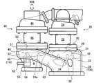
- FIG. 2 is a plan view (top view) showing the housing of the multistage turbocharger according to the present embodiment.
- FIG. 3 is a front view showing the turbine housing according to the present embodiment.
- FIG. 1 is a schematic configuration diagram of a supercharging system including a multistage supercharger according to the present embodiment.
- the supercharging system 10 of this embodiment is applied to, for example, the engine system 100 shown in FIG. Therefore, first, the engine system 100 will be described.
- the engine system 100 includes a supercharging system 10, an engine 101, an intercooler 102, a purification device 103, and an ECU (Engine Control Unit) 104.
- the engine system 100 is mounted on a vehicle, for example.
- the engine 101 is a power source of a vehicle on which the engine system 100 is mounted.
- the engine 101 is an internal combustion engine, and generates power by burning an air-fuel mixture of air compressed by the supercharging system 10 and fuel.
- the engine 101 burns the air-fuel mixture and supplies exhaust gas generated by the combustion to the supercharging system 10.
- the intercooler 102 cools the compressed air supplied from the supercharging system 10 to the engine 101.
- the inlet side of the intercooler 102 is connected to a first compressor (described later) 21 and a second compressor (described later) 41 of the supercharging system 10 described later, and the outlet side of the intercooler 102 is connected via an intake manifold 105 of the engine 101. It is connected to the supercharging system 10.
- the purification device 103 purifies the exhaust gas discharged from the supercharging system 10.
- the purification device 103 includes, for example, a filter that collects particulate matter, a catalyst that promotes an oxidation reaction or reduction reaction of harmful components, and the like.
- the ECU 104 controls the entire engine system 100.
- the ECU 105 determines an intake switching valve (described later) 60 and an exhaust switching valve (described later) in the supercharging system 10 according to the output of the engine 101 (for example, the rotational speed and the flow rate of exhaust gas expected from the rotational speed).
- 61 and a waste gate valve (described later) 62 are controlled and the opening degree thereof is controlled.
- a supercharging system 10 compresses air using the exhaust gas of the engine 101 and supplies the compressed air to the engine 101.
- a supercharging system 10 includes a first supercharger (primary supercharger, high-pressure supercharger) 20 and a second supercharger (secondary supercharger, low-pressure supercharger). 40, an intake switching valve 60, an exhaust switching valve 61, and a waste gate valve 62.
- the first supercharger 20 and the second supercharger 40 are arranged in series in the exhaust gas flow direction. That is, the supercharging system 10 of this embodiment employs a series type multistage supercharger.
- the first supercharger 20 is disposed upstream of the second supercharger 40 in the exhaust gas flow direction.
- the first supercharger 20 includes a first compressor (high pressure stage compressor) 21 and a first turbine (high pressure stage turbine) 22.
- the first supercharger 20 may include a variable nozzle unit (not shown) that adjusts the exhaust gas ejection speed toward the first turbine 22.
- the first compressor 21 includes a first compressor impeller 23 and a first compressor housing 24 that rotatably accommodates the first compressor impeller 23.
- the first turbine 22 includes a first turbine impeller 25 and a first turbine housing (first sub-housing) 26 that rotatably accommodates the first turbine impeller 25.
- the first shaft 27 connects the first compressor impeller 23 and the first turbine impeller 25 and is rotatably supported by this bearing (not shown).
- a bearing (not shown) is attached to the first bearing housing 28.
- the second supercharger 40 is disposed downstream of the first supercharger 20 in the exhaust gas flow direction, and has a larger capacity than the first supercharger 20.
- the second supercharger 40 includes a second compressor (low pressure stage compressor) 41 and a second turbine (low pressure stage turbine) 42.
- the second supercharger 40 may include a variable nozzle unit (not shown) that adjusts the exhaust gas ejection speed toward the second turbine 42.
- the second compressor 41 includes a second compressor impeller 43 and a second compressor housing 44 that rotatably accommodates the second compressor impeller 43.
- the second turbine 42 includes a second turbine impeller 45 and a second turbine housing (second sub-housing) 46 that rotatably accommodates the second turbine impeller 45.
- the second shaft 47 connects the second compressor impeller 43 and the second turbine impeller 45 and is rotatably supported by this bearing (not shown).
- a bearing (not shown) is attached to the second bearing housing 48.
- the first turbine housing 26 of the first turbine 22 and the second turbine housing 46 of the second turbine 42 are integrally formed as a single turbine housing TH (see FIG. 2). That is, the first turbine housing 26 and the second turbine housing 46 are connected to each other without a connection member such as a flange.
- the intake switching valve 60 is provided in a bypass flow path 63 that communicates the intake side and the discharge side of the first compressor 21 while bypassing the first compressor 21, and opens and closes the bypass flow path 63.
- the intake air switching valve 60 is closed when the first compressor 21 is driven. In this case, the compressed air discharged from the second compressor 41 flows into the first compressor 21 and is compressed, and is supplied to the intake side of the engine 101 via the intake manifold 105.
- the intake air switching valve 60 is opened when the first compressor 21 is not driven.
- the compressed air discharged from the second compressor 41 is supplied to the intake side of the engine 101 via the intake manifold 105 while bypassing the first compressor 21. That is, the intake air switching valve 60 allows the flow of compressed air from the second compressor 41 to the engine 101 via the bypass flow path 63.
- the intake air switching valve 60 is configured to prevent the backflow of compressed air from the engine 101 to the second compressor 41. That is, the intake air switching valve 60 also functions as a so-called check valve.
- the exhaust switching valve 61 is provided in a bypass passage 64 that communicates the intake side and the discharge side of the first turbine 22 while bypassing the first turbine 22, and opens and closes the bypass passage 64. While the exhaust gas switching valve 61 is closed, the exhaust gas discharged from the engine 101 passes through the first turbine impeller 25 of the first supercharger 20 and is then discharged from the first supercharger 20. As a result, the first turbine impeller 25 rotates, and the first compressor 21 performs air compression by this rotation.
- the exhaust gas switching valve 61 while the exhaust gas switching valve 61 is open, the exhaust gas discharged from the engine 101 passes through the bypass flow path 64 and is discharged from the first supercharger 20 and then supplied to the second supercharger 40. Is done. In other words, the exhaust gas bypasses the first turbine impeller 25 and is discharged from the first supercharger 20 and supplied to the second supercharger 40. That is, the exhaust gas switching valve 61 stops the compression of the air performed by the first compressor 21 by opening the bypass passage 64.
- the waste gate valve 62 is provided in the bypass passage 65 that communicates the intake side and the discharge side of the second turbine 42 while bypassing the second turbine 42, and opens and closes the bypass passage 65. While the waste gate valve 62 is open, a part of the exhaust gas passes through the bypass passage 65, is discharged from the second supercharger 40, and then flows into the purification device 103. In other words, a part of the exhaust gas is discharged from the second supercharger 40 by bypassing the second turbine impeller 45 and then flows into the purification device 103.
- the opening degree of the waste gate valve 62 is adjusted by the supercharging pressure of the ECU 105 or the second compressor 41.
- the opening degree of the waste gate valve 62 changes according to the supercharging pressure or the like required by the engine 101. That is, the opening degree of the waste gate valve 62 changes from fully open to fully closed. Thereby, the amount of exhaust gas flowing into the second turbine impeller 45 (that is, the rotational speeds of the second turbine impeller 45 and the second compressor impeller 43) can be adjusted.
- FIG. 2 is a plan view (top view) showing the housing of the multistage turbocharger according to the present embodiment.
- FIG. 3 is a front view showing the turbine housing according to the present embodiment.
- the housing of the first supercharger 20 includes a first turbine housing 26, a first compressor housing 24, and a first bearing housing 28.
- a first turbine housing 26 is connected to one end of the first bearing housing 28, and a first compressor housing is connected to the other end of the first bearing housing 28.
- the first compressor housing 24 is connected to the first turbine housing 26 via the first bearing housing 28.
- the housing of the second supercharger 40 includes a second turbine housing 46, a second compressor housing 44, and a second bearing housing 48.
- a second turbine housing 46 is connected to one end of the second bearing housing 48, and a first compressor housing is connected to the other end of the second bearing housing 48.
- the second compressor housing 44 is connected to the second turbine housing 46 via the second bearing housing 48.
- each housing of the 1st supercharger 20 and the 2nd supercharger 40 is formed by casting, for example.
- first turbine housing 26 and the second turbine housing 46 are integrally formed as a single turbine housing TH. That is, the first turbine housing 26 and the second turbine housing 46 are connected to each other without using a connecting member such as a flange, and constitute a turbine housing TH as a single structure.
- the first turbine housing 26 has a first turbine impeller accommodating chamber 29.
- the first turbine impeller accommodating chamber 29 includes an axisymmetric shape that matches the shape of the first turbine impeller 25 and accommodates the first turbine impeller 25.
- the first turbine impeller accommodating chamber 29 has an insertion port 30 for the first turbine impeller 25.
- the insertion port 30 is open to a flange (rib) 31 facing the first bearing housing 28.
- the first turbine housing 26 includes a first scroll passage 32, a first intake passage 33, and a first exhaust passage 34.
- the first scroll flow path 32 is provided on the outer periphery of the first turbine impeller accommodating chamber 29 and communicates with the first scroll flow path 32.
- the first scroll flow path 32 extends spirally in the circumferential direction of the first turbine impeller 25 with reference to the symmetry axis of the first turbine impeller accommodating chamber 29 (in other words, the rotation center axis of the first turbine impeller). . Further, the cross-sectional area of the first scroll passage 32 gradually decreases from the winding start side along the flow direction of the exhaust gas.
- the first intake passage 33 is connected to the end portion on the winding start side of the first scroll passage 32 (that is, the portion having the largest cross-sectional area).
- the first intake passage 33 opens to a flange (rib) 35 of the first turbine housing 26 and is connected to the exhaust manifold 106 of the engine 101.
- the flange 35 is located on the opposite side of the flange 31 with the first turbine impeller accommodating chamber 29 interposed therebetween.
- the first exhaust path 34 (one end side of the first exhaust path 34) communicates with the first turbine impeller accommodating chamber 29 so as to open toward the rear edge (trailing edge) of the first turbine impeller 25. .
- the first exhaust passage 34 (the other end side of the first exhaust passage 34) communicates with the second intake passage 53 of the second supercharger 40 inside the first turbine housing 26.
- the second turbine housing 46 has a second turbine impeller accommodating chamber 49.
- the second turbine impeller accommodating chamber 49 includes an axisymmetric shape that matches the shape of the second turbine impeller 45 and accommodates the second turbine impeller 45.
- the second turbine impeller accommodating chamber 49 has an insertion port 50 for the second turbine impeller 45.
- the insertion port 50 is open to a flange (rib) 51 facing the second bearing housing 48.
- the supercharging system 10 of the present embodiment employs a series-type multistage supercharger. Therefore, the first turbine impeller accommodating chamber 29 of the first turbine housing 26 and the second turbine impeller accommodating chamber 49 of the second turbine housing 46 are arranged in series in the exhaust gas flow direction in the turbine housing TH.
- the second turbine housing 46 includes a second scroll passage 52, a second intake passage 53, and a second exhaust passage 54.
- the second scroll passage 52 is provided on the outer periphery of the second turbine impeller housing chamber 49 and communicates with the second scroll passage 52.
- the second scroll passage 52 extends spirally in the circumferential direction of the second turbine impeller 45 with reference to the axis of symmetry of the second turbine impeller accommodating chamber 49 (in other words, the rotation center axis of the second turbine impeller). . Further, the cross-sectional area of the second scroll channel 52 gradually decreases along the flow direction of the exhaust gas from the winding start side.
- the second intake passage 53 is connected to the end of the second scroll passage 52 on the winding start side (that is, the portion having the largest cross-sectional area).
- the second intake passage 53 extends from the second scroll passage 52 to the flange 35 of the first turbine housing 26 and opens at the flange 35. That is, the first intake passage 33 and the second intake passage 53 are open to the same flange 35.
- the second intake passage 53 is connected to the exhaust manifold 106 of the engine 101 via the exhaust switching valve 61.
- the second intake passage 53 is formed in a cylindrical shape, and its cross-sectional area (opening area) gradually increases from the second scroll passage 52 toward the flange 35.
- the second intake passage 53 is not structurally divided between the second scroll passage 52 and the flange 35. That is, the second intake passage 53 does not have a joint structure (for example, a flange) for connecting the first turbine housing 26 and the second turbine housing 46.
- the second exhaust passage 54 (one end side of the second exhaust passage 54) communicates with the second turbine impeller accommodating chamber 49 so as to open toward the rear edge (trailing edge) of the second turbine impeller 45. . Further, the second exhaust passage 54 (the other end side of the second exhaust passage 54) opens to a flange (rib) 55 of the second turbine housing 46. The flange 55 is located on the opposite side of the flange 51 with the second turbine impeller accommodating chamber 49 interposed therebetween.
- the waste gate valve 62 is installed in the second turbine housing 46.
- the bypass passage 65 is formed in the inner wall 53 a of the second intake passage 53 and communicates with the second exhaust passage 54.
- the waste gate valve 62 opens and closes the second intake path 53 side of the second exhaust path 54.
- first turbine housing (first sub housing) 26 and the second turbine housing (second sub housing) 46 are integrally formed as a single turbine housing TH. That is, the joint structure (for example, flange) for connecting each housing becomes unnecessary. Therefore, it is possible to reduce the size of the multistage turbocharger while ensuring the expansion of the operating range.
- the piping constituting the second intake passage 53 connects the first turbine housing 26 and the second turbine housing 46.
- the inlet side of the second intake passage 53 of the second supercharger 40 is integrated with the first turbine housing 26 of the first supercharger 20.
- the first turbine housing 26 and the second turbine housing 46 may be connected to each other via the second intake passage 53 and may be separated from each other.
- the first turbine housing 26 and the second turbine housing 46 may be provided via a gap except for the second intake passage 53.
- the second intake passage 53 functions as an elastic body, and the mutual influence (for example, mixing of stress) of the thermal deformation of the first turbine housing 26 and the thermal deformation of the second turbine housing 46 accompanying the circulation of the exhaust gas. Is suppressed (insulated) as much as possible. Moreover, since the mutual heat flow between the 1st turbine housing 26 and the 2nd turbine housing 46 is suppressed, the heat loss by such a heat flow can also be suppressed.
- the thickness of the piping constituting the second intake passage 53 may be set to a value as small as possible as long as the connection between the first turbine housing 26 and the second turbine housing 46 and the prevention of exhaust gas leakage can be maintained. Since the heat capacity of the pipe decreases as the pipe thickness decreases, at least heat loss of the exhaust gas flowing through the second intake passage 53 can be suppressed.
- the flange 35 and the flange 55 may be located in parallel to each other. That is, the first intake passage 33, the second intake passage 53, and the second exhaust passage 54 may be open in the same direction.
- “same” here means “substantially identical”, in other words, “substantially identical”, and these do not require opening in exactly the same direction. In this case, since the ratio that these related members are located in the direction in which each flow path opens increases, workability is improved.
- the second intake passage 53 may be inclined with respect to the surface R on which the second scroll passage 52 extends.
- the surface R is, for example, a plane orthogonal to the symmetry axis of the second turbine impeller accommodating chamber 49. Since it can be avoided that the flow direction of the exhaust gas flowing through the second scroll passage 52 via the second intake passage 53 is abruptly deflected, reduction in turbine efficiency can be suppressed.
- the first compressor housing 24 and the second compressor housing 44 may be formed separately. In this case, it is desirable that the pipe connecting the first compressor housing 24 and the second compressor housing 44 has a structure that gives flexibility. As described above, the first turbine housing 26 and the second turbine housing 46 are thermally deformed as the exhaust gas flows. By forming the first compressor housing 24 and the second compressor housing 44 individually, it is possible to suppress the generation of new stress due to the deformation of the turbine housings having different degrees.
Abstract
L'invention concerne un compresseur de suralimentation à plusieurs étages comprenant : un carter de turbine (TH) comprenant un premier sous-carter (26) qui comporte une première chambre (29) contenant une roue de turbine, et comprenant également un second sous-carter (46) qui comporte une seconde chambre (49) contenant une roue de turbine, disposée en série avec la première chambre (29) contenant une roue de turbine ; un premier carter de compresseur (24), relié au carter de turbine (TH) par l'intermédiaire d'un premier corps de palier (28) ; et un second carter de compresseur (44), relié au carter de turbine (TH) par l'intermédiaire d'un second corps de palier (48). Le premier sous-carter (26) et le second sous-carter (46) sont formés d'un seul tenant.
Priority Applications (4)
| Application Number | Priority Date | Filing Date | Title |
|---|---|---|---|
| DE112018002996.4T DE112018002996T5 (de) | 2017-06-13 | 2018-04-03 | Mehrstufiger Turbolader |
| CN201880030166.4A CN110603376B (zh) | 2017-06-13 | 2018-04-03 | 多级增压器 |
| JP2019525120A JP6780778B2 (ja) | 2017-06-13 | 2018-04-03 | 多段過給機 |
| US16/674,623 US11078830B2 (en) | 2017-06-13 | 2019-11-05 | Multi-stage turbocharger |
Applications Claiming Priority (2)
| Application Number | Priority Date | Filing Date | Title |
|---|---|---|---|
| JP2017-115831 | 2017-06-13 | ||
| JP2017115831 | 2017-06-13 |
Related Child Applications (1)
| Application Number | Title | Priority Date | Filing Date |
|---|---|---|---|
| US16/674,623 Continuation US11078830B2 (en) | 2017-06-13 | 2019-11-05 | Multi-stage turbocharger |
Publications (1)
| Publication Number | Publication Date |
|---|---|
| WO2018230108A1 true WO2018230108A1 (fr) | 2018-12-20 |
Family
ID=64659172
Family Applications (1)
| Application Number | Title | Priority Date | Filing Date |
|---|---|---|---|
| PCT/JP2018/014282 WO2018230108A1 (fr) | 2017-06-13 | 2018-04-03 | Compresseur de suralimentation à plusieurs étages |
Country Status (5)
| Country | Link |
|---|---|
| US (1) | US11078830B2 (fr) |
| JP (1) | JP6780778B2 (fr) |
| CN (1) | CN110603376B (fr) |
| DE (1) | DE112018002996T5 (fr) |
| WO (1) | WO2018230108A1 (fr) |
Cited By (1)
| Publication number | Priority date | Publication date | Assignee | Title |
|---|---|---|---|---|
| DE102020100386A1 (de) * | 2020-01-10 | 2021-07-15 | Bayerische Motoren Werke Aktiengesellschaft | Gehäusebauteil für ein Turbinengehäuse eines Abgasturboladers |
Citations (6)
| Publication number | Priority date | Publication date | Assignee | Title |
|---|---|---|---|---|
| JP2003531996A (ja) * | 2000-04-20 | 2003-10-28 | ボーグワーナー・インコーポレーテッド | 内燃機関用ターボチャージャ装置 |
| JP2004092646A (ja) * | 2002-08-30 | 2004-03-25 | Borgwarner Inc | 内燃機関用過給装置 |
| WO2010122668A1 (fr) * | 2009-04-24 | 2010-10-28 | トヨタ自動車 株式会社 | Système de turbocompresseur pour moteurs à combustion interne |
| JP2010255565A (ja) * | 2009-04-27 | 2010-11-11 | Toyota Motor Corp | 内燃機関 |
| JP2010261362A (ja) * | 2009-05-07 | 2010-11-18 | Toyota Motor Corp | エンジンの過給装置 |
| US20110020108A1 (en) * | 2006-04-05 | 2011-01-27 | Gm Global Technology Operations, Inc. | Two-stage turbo-charger engine system |
Family Cites Families (25)
| Publication number | Priority date | Publication date | Assignee | Title |
|---|---|---|---|---|
| JPS6040728A (ja) * | 1983-08-11 | 1985-03-04 | Fuji Heavy Ind Ltd | 過給機付エンジン |
| DE19822874A1 (de) | 1998-05-22 | 1999-11-25 | Man Nutzfahrzeuge Ag | Aufladesystem für Brennkraftmaschinen |
| JP4479502B2 (ja) * | 2004-12-28 | 2010-06-09 | トヨタ自動車株式会社 | 内燃機関用多段過給システム及びその制御方法 |
| IL170165A (en) * | 2005-08-08 | 2010-12-30 | Haim Rom | Wankel and similar rotary engines |
| DE102005039756A1 (de) * | 2005-08-23 | 2007-03-01 | Robert Bosch Gmbh | Aufladeeinrichtung mit zweistufiger Niederdruckturbine |
| JP4495120B2 (ja) * | 2006-08-10 | 2010-06-30 | 三菱重工業株式会社 | 多段過給式排気ターボ過給機 |
| GB0717212D0 (en) * | 2007-09-05 | 2007-10-17 | Cummins Turbo Tech Ltd | Multi-stage turbocharger system |
| JP4875586B2 (ja) * | 2007-10-12 | 2012-02-15 | 三菱重工業株式会社 | 2段過給式排気ターボ過給機 |
| US8206133B2 (en) * | 2008-08-12 | 2012-06-26 | GM Global Technology Operations LLC | Turbocharger housing with integral inlet and outlet openings |
| GB2464500B (en) * | 2008-10-17 | 2013-02-20 | Cummins Turbo Tech Ltd | An internal combustion engine with exhaust gas recirculation |
| US8266906B2 (en) * | 2009-03-11 | 2012-09-18 | GM Global Technology Operations LLC | Asymmetric split-inlet turbine housing |
| JP2010281282A (ja) * | 2009-06-05 | 2010-12-16 | Toyota Motor Corp | 過給装置及びこれを備える内燃機関 |
| US8863514B2 (en) * | 2009-06-29 | 2014-10-21 | Borgwarner Inc. | Multi-stage turbocharger arrangement |
| JP2011085043A (ja) * | 2009-10-14 | 2011-04-28 | Ihi Corp | ターボチャージャ及び過給装置 |
| GB2475534B (en) * | 2009-11-21 | 2014-11-12 | Cummins Turbo Tech Ltd | Sequential two-stage turbocharger system |
| JP2011174425A (ja) | 2010-02-25 | 2011-09-08 | Honda Motor Co Ltd | 内燃機関の多段過給装置 |
| JP5471899B2 (ja) * | 2010-06-30 | 2014-04-16 | マツダ株式会社 | 車両用エンジンのターボ過給機の潤滑装置 |
| JP5874161B2 (ja) * | 2010-10-28 | 2016-03-02 | いすゞ自動車株式会社 | ターボ過給システム |
| JP5879685B2 (ja) * | 2010-12-28 | 2016-03-08 | いすゞ自動車株式会社 | 多段過給装置 |
| WO2012121925A2 (fr) * | 2011-03-04 | 2012-09-13 | Borgwarner Inc. | Agencement de turbocompresseur multi-étagé |
| GB2500192B (en) * | 2012-03-12 | 2015-11-18 | Jaguar Land Rover Ltd | Compact Multi-Stage Turbo Pump |
| CN102606285A (zh) * | 2012-04-07 | 2012-07-25 | 潍坊富源增压器有限公司 | 两级增压的涡轮增压器 |
| CN103615305B (zh) * | 2013-11-29 | 2016-01-20 | 长城汽车股份有限公司 | 一种涡轮增压器 |
| US9441531B2 (en) * | 2014-01-02 | 2016-09-13 | Caterpillar Inc. | Diverter valve for charge air system |
| GB2533351A (en) * | 2014-12-17 | 2016-06-22 | Gm Global Tech Operations Inc | Internal combustion engine having a two stage turbocharger |
-
2018
- 2018-04-03 WO PCT/JP2018/014282 patent/WO2018230108A1/fr active Application Filing
- 2018-04-03 JP JP2019525120A patent/JP6780778B2/ja active Active
- 2018-04-03 DE DE112018002996.4T patent/DE112018002996T5/de active Pending
- 2018-04-03 CN CN201880030166.4A patent/CN110603376B/zh active Active
-
2019
- 2019-11-05 US US16/674,623 patent/US11078830B2/en active Active
Patent Citations (6)
| Publication number | Priority date | Publication date | Assignee | Title |
|---|---|---|---|---|
| JP2003531996A (ja) * | 2000-04-20 | 2003-10-28 | ボーグワーナー・インコーポレーテッド | 内燃機関用ターボチャージャ装置 |
| JP2004092646A (ja) * | 2002-08-30 | 2004-03-25 | Borgwarner Inc | 内燃機関用過給装置 |
| US20110020108A1 (en) * | 2006-04-05 | 2011-01-27 | Gm Global Technology Operations, Inc. | Two-stage turbo-charger engine system |
| WO2010122668A1 (fr) * | 2009-04-24 | 2010-10-28 | トヨタ自動車 株式会社 | Système de turbocompresseur pour moteurs à combustion interne |
| JP2010255565A (ja) * | 2009-04-27 | 2010-11-11 | Toyota Motor Corp | 内燃機関 |
| JP2010261362A (ja) * | 2009-05-07 | 2010-11-18 | Toyota Motor Corp | エンジンの過給装置 |
Cited By (1)
| Publication number | Priority date | Publication date | Assignee | Title |
|---|---|---|---|---|
| DE102020100386A1 (de) * | 2020-01-10 | 2021-07-15 | Bayerische Motoren Werke Aktiengesellschaft | Gehäusebauteil für ein Turbinengehäuse eines Abgasturboladers |
Also Published As
| Publication number | Publication date |
|---|---|
| JP6780778B2 (ja) | 2020-11-04 |
| JPWO2018230108A1 (ja) | 2020-03-19 |
| US20200063645A1 (en) | 2020-02-27 |
| DE112018002996T5 (de) | 2020-03-05 |
| CN110603376B (zh) | 2021-09-07 |
| US11078830B2 (en) | 2021-08-03 |
| CN110603376A (zh) | 2019-12-20 |
Similar Documents
| Publication | Publication Date | Title |
|---|---|---|
| US7950227B2 (en) | High response compact turbocharger | |
| US8281588B2 (en) | Turbomachine system and turbine therefor | |
| JP4273340B2 (ja) | 吸気管内にコンプレッサを具備する内燃機関 | |
| JP5369723B2 (ja) | 遠心圧縮機 | |
| US7874789B2 (en) | Compressor and compressor housing | |
| JP2007154675A (ja) | 内燃機関 | |
| US20140093364A1 (en) | Double flow turbine housing turbocharger | |
| JP5918396B2 (ja) | コンパクトなマルチステージ型ターボポンプ | |
| WO2012090662A1 (fr) | Dispositif de suralimentation à étages multiples | |
| EP1853825A1 (fr) | Turbocompresseur comprenant une gaine de deuxieme etage a ouvertures et procede associe | |
| JP2009047163A (ja) | 効率範囲が広い出力タービンを備えた内燃機関装置 | |
| EP3133289B1 (fr) | Turbocompresseur avec compresseur pouvant fonctionner en mode à un seul étage ou en mode série en deux étapes | |
| JP6780714B2 (ja) | 過給機 | |
| EP3438429B1 (fr) | Moteur comprenant un turbocompresseur | |
| JP2011106358A (ja) | 多段式過給機 | |
| JP2012529585A (ja) | 圧縮機インペラ | |
| WO2018230108A1 (fr) | Compresseur de suralimentation à plusieurs étages | |
| JP2012002140A (ja) | タービン及び過給機 | |
| CN108431385B (zh) | 涡轮增压器压缩机和方法 | |
| CN111350555A (zh) | 带流量控制阀的双涡卷涡轮 | |
| WO2024053148A1 (fr) | Turbine | |
| WO2022202078A1 (fr) | Turbine et compresseur de suralimentation | |
| JP2008303849A (ja) | 複数段過給ターボチャージャ |
Legal Events
| Date | Code | Title | Description |
|---|---|---|---|
| 121 | Ep: the epo has been informed by wipo that ep was designated in this application |
Ref document number: 18816796 Country of ref document: EP Kind code of ref document: A1 |
|
| ENP | Entry into the national phase |
Ref document number: 2019525120 Country of ref document: JP Kind code of ref document: A |
|
| NENP | Non-entry into the national phase |
Ref country code: DE |
|
| 122 | Ep: pct application non-entry in european phase |
Ref document number: 18816796 Country of ref document: EP Kind code of ref document: A1 |