WO2018207758A1 - 弁付き針組立体 - Google Patents
弁付き針組立体 Download PDFInfo
- Publication number
- WO2018207758A1 WO2018207758A1 PCT/JP2018/017720 JP2018017720W WO2018207758A1 WO 2018207758 A1 WO2018207758 A1 WO 2018207758A1 JP 2018017720 W JP2018017720 W JP 2018017720W WO 2018207758 A1 WO2018207758 A1 WO 2018207758A1
- Authority
- WO
- WIPO (PCT)
- Prior art keywords
- end side
- valve
- protrusion
- valve member
- needle
- Prior art date
- Legal status (The legal status is an assumption and is not a legal conclusion. Google has not performed a legal analysis and makes no representation as to the accuracy of the status listed.)
- Ceased
Links
Images



Classifications
-
- A—HUMAN NECESSITIES
- A61—MEDICAL OR VETERINARY SCIENCE; HYGIENE
- A61M—DEVICES FOR INTRODUCING MEDIA INTO, OR ONTO, THE BODY; DEVICES FOR TRANSDUCING BODY MEDIA OR FOR TAKING MEDIA FROM THE BODY; DEVICES FOR PRODUCING OR ENDING SLEEP OR STUPOR
- A61M39/00—Tubes, tube connectors, tube couplings, valves, access sites or the like, specially adapted for medical use
- A61M39/02—Access sites
- A61M39/06—Haemostasis valves, i.e. gaskets sealing around a needle, catheter or the like, closing on removal thereof
-
- A—HUMAN NECESSITIES
- A61—MEDICAL OR VETERINARY SCIENCE; HYGIENE
- A61M—DEVICES FOR INTRODUCING MEDIA INTO, OR ONTO, THE BODY; DEVICES FOR TRANSDUCING BODY MEDIA OR FOR TAKING MEDIA FROM THE BODY; DEVICES FOR PRODUCING OR ENDING SLEEP OR STUPOR
- A61M25/00—Catheters; Hollow probes
-
- A—HUMAN NECESSITIES
- A61—MEDICAL OR VETERINARY SCIENCE; HYGIENE
- A61M—DEVICES FOR INTRODUCING MEDIA INTO, OR ONTO, THE BODY; DEVICES FOR TRANSDUCING BODY MEDIA OR FOR TAKING MEDIA FROM THE BODY; DEVICES FOR PRODUCING OR ENDING SLEEP OR STUPOR
- A61M5/00—Devices for bringing media into the body in a subcutaneous, intra-vascular or intramuscular way; Accessories therefor, e.g. filling or cleaning devices, arm-rests
- A61M5/14—Infusion devices, e.g. infusing by gravity; Blood infusion; Accessories therefor
- A61M5/158—Needles for infusions; Accessories therefor, e.g. for inserting infusion needles, or for holding them on the body
-
- A—HUMAN NECESSITIES
- A61—MEDICAL OR VETERINARY SCIENCE; HYGIENE
- A61M—DEVICES FOR INTRODUCING MEDIA INTO, OR ONTO, THE BODY; DEVICES FOR TRANSDUCING BODY MEDIA OR FOR TAKING MEDIA FROM THE BODY; DEVICES FOR PRODUCING OR ENDING SLEEP OR STUPOR
- A61M5/00—Devices for bringing media into the body in a subcutaneous, intra-vascular or intramuscular way; Accessories therefor, e.g. filling or cleaning devices, arm-rests
- A61M5/178—Syringes
- A61M5/31—Details
- A61M5/32—Needles; Details of needles pertaining to their connection with syringe or hub; Accessories for bringing the needle into, or holding the needle on, the body; Devices for protection of needles
- A61M5/34—Constructions for connecting the needle, e.g. to syringe nozzle or needle hub
- A61M5/344—Constructions for connecting the needle, e.g. to syringe nozzle or needle hub using additional parts, e.g. clamping rings or collets
-
- A—HUMAN NECESSITIES
- A61—MEDICAL OR VETERINARY SCIENCE; HYGIENE
- A61M—DEVICES FOR INTRODUCING MEDIA INTO, OR ONTO, THE BODY; DEVICES FOR TRANSDUCING BODY MEDIA OR FOR TAKING MEDIA FROM THE BODY; DEVICES FOR PRODUCING OR ENDING SLEEP OR STUPOR
- A61M5/00—Devices for bringing media into the body in a subcutaneous, intra-vascular or intramuscular way; Accessories therefor, e.g. filling or cleaning devices, arm-rests
- A61M5/178—Syringes
- A61M5/31—Details
- A61M2005/3128—Incorporating one-way valves, e.g. pressure-relief or non-return valves
-
- A—HUMAN NECESSITIES
- A61—MEDICAL OR VETERINARY SCIENCE; HYGIENE
- A61M—DEVICES FOR INTRODUCING MEDIA INTO, OR ONTO, THE BODY; DEVICES FOR TRANSDUCING BODY MEDIA OR FOR TAKING MEDIA FROM THE BODY; DEVICES FOR PRODUCING OR ENDING SLEEP OR STUPOR
- A61M39/00—Tubes, tube connectors, tube couplings, valves, access sites or the like, specially adapted for medical use
- A61M39/02—Access sites
- A61M39/06—Haemostasis valves, i.e. gaskets sealing around a needle, catheter or the like, closing on removal thereof
- A61M2039/062—Haemostasis valves, i.e. gaskets sealing around a needle, catheter or the like, closing on removal thereof used with a catheter
-
- A—HUMAN NECESSITIES
- A61—MEDICAL OR VETERINARY SCIENCE; HYGIENE
- A61M—DEVICES FOR INTRODUCING MEDIA INTO, OR ONTO, THE BODY; DEVICES FOR TRANSDUCING BODY MEDIA OR FOR TAKING MEDIA FROM THE BODY; DEVICES FOR PRODUCING OR ENDING SLEEP OR STUPOR
- A61M39/00—Tubes, tube connectors, tube couplings, valves, access sites or the like, specially adapted for medical use
- A61M39/02—Access sites
- A61M39/06—Haemostasis valves, i.e. gaskets sealing around a needle, catheter or the like, closing on removal thereof
- A61M2039/0633—Haemostasis valves, i.e. gaskets sealing around a needle, catheter or the like, closing on removal thereof the seal being a passive seal made of a resilient material with or without an opening
- A61M2039/064—Slit-valve
-
- A—HUMAN NECESSITIES
- A61—MEDICAL OR VETERINARY SCIENCE; HYGIENE
- A61M—DEVICES FOR INTRODUCING MEDIA INTO, OR ONTO, THE BODY; DEVICES FOR TRANSDUCING BODY MEDIA OR FOR TAKING MEDIA FROM THE BODY; DEVICES FOR PRODUCING OR ENDING SLEEP OR STUPOR
- A61M5/00—Devices for bringing media into the body in a subcutaneous, intra-vascular or intramuscular way; Accessories therefor, e.g. filling or cleaning devices, arm-rests
- A61M5/178—Syringes
- A61M5/31—Details
- A61M5/32—Needles; Details of needles pertaining to their connection with syringe or hub; Accessories for bringing the needle into, or holding the needle on, the body; Devices for protection of needles
- A61M5/3293—Needles; Details of needles pertaining to their connection with syringe or hub; Accessories for bringing the needle into, or holding the needle on, the body; Devices for protection of needles characterised by features of the needle hub
Definitions
- the present invention relates to a needle assembly used when performing, for example, infusion, blood collection, hemodialysis, and the like, and particularly to a needle assembly with a valve provided with a valve for preventing leakage of blood or the like.
- a needle assembly with a valve has been used for blood collection, blood transfusion, infusion, etc. to a patient.
- a needle hub is provided on the proximal end side of the hollow needle so that a connector, a luer, or the like can be connected.
- a valve member that blocks communication with the hollow needle is incorporated inside the needle hub, and the needle hole of the hollow needle is opened to the atmosphere through the needle hub with no connector or luer connected. Not to be. That is, the valve member prevents blood leakage when the needle assembly is punctured into a patient's blood vessel, for example.
- valve-attached needle assembly is known to have a structure as described in, for example, European Patent No. 0414997 (Patent Document 1).
- the object of the present invention is to contribute to the enrichment of specific technology and, in turn, products, by providing a needle assembly with a valve having a novel structure that has not existed before.
- a needle assembly with a valve in which a valve member for blocking communication with the hollow needle is incorporated in a needle hub provided on a proximal end side of the hollow needle. Is provided with a protrusion projecting from the distal end side toward the proximal end side, and the proximal end side of the protrusion inside the needle hub is blocked by the valve member. While the central valve portion of the valve member having the slit formed at the opposite position is moved toward the protrusion, the slit is opened at the protrusion and is brought into a communication state.
- the distal end side cylindrical portion extending from the outer peripheral portion toward the distal end side and the proximal end side cylindrical portion extending from the outer peripheral portion toward the proximal end side are provided with respect to the central valve portion. It is a feature.
- the position of the valve member in the needle hub is determined by the tubular portions on the distal end side and the proximal end side respectively extending from the central valve portion toward both the inside and outside of the needle hub. Stable and excessive tilting of the valve member in the needle hub is prevented. As a result, the central valve portion can be smoothly moved toward the protrusion, and the protrusion can be more accurately pressed against the central valve portion, and the slit can be stably opened.
- the entire valve member including the central valve portion is easily directed toward the distal end side by the space on the distal end side. It can be moved to.
- the valve member protrudes on the outer peripheral surface and moves in contact with the inner peripheral surface of the needle hub. Protrusions are provided.
- the guide action during the movement of the valve member is improved, and the movement can be further stabilized. That is, the central valve portion of the valve member can be moved more straight in the axial direction with respect to the protrusion. Further, the sliding contact resistance is reduced as compared with the case where the entire outer peripheral surface of the valve member is brought into contact with the inner peripheral surface of the needle hub, and for example, the valve member is locally disposed on the inner periphery of the needle hub. It is possible to avoid lifting from the surface and stabilize the contact state.
- an inner peripheral surface of the distal-end-side cylindrical portion of the valve member is formed by the protrusion of the needle hub. It has a guide surface that is in contact with the outer peripheral surface.
- the inner peripheral surface of the distal end side tubular portion of the valve member and the outer peripheral surface of the protruding portion of the needle hub are brought into contact with each other to exhibit a guide function.
- the central valve portion of the valve member can be moved more straightly toward the distal end side.
- the protrusion of the needle hub is a cylindrical protrusion formed in a cylindrical shape
- the inner peripheral surface of the distal end side cylindrical portion of the valve member has a seal surface that is in contact with the outer peripheral surface of the cylindrical protrusion of the needle hub over the entire circumference.
- the inner peripheral surface of the distal cylindrical portion of the valve member and the outer peripheral surface of the cylindrical protrusion of the needle hub are in contact with each other over the entire circumference. Since the sealing function is exhibited, it is possible to prevent blood from leaking into the needle hub (for example, the inner space on the tip side of the valve member) and staying in the needle hub. In particular, by bringing the seal surface into contact with the protruding end of the cylindrical protrusion of the needle hub, the space between the valve member and the cylindrical protrusion can be kept small, and blood in the space can be kept small. Stagnation can also be effectively prevented.
- the distal end side tubular portion of the valve member is provided with an annular seal protrusion projecting toward the inner periphery.
- the inner peripheral surface of the annular seal protrusion is the seal surface.
- the annular seal protrusion is provided on the distal end-side cylindrical portion, and the inner peripheral surface of the annular seal protrusion is formed by the cylindrical protrusion of the needle hub.
- the axial direction By forming a narrow sealing surface, the sealing performance can be improved and stabilized.
- the distal-end-side tubular portion of the valve member is pushed and expanded with respect to the tubular protrusion.
- a tightening fitting portion that is externally fitted in an expanded state is provided, and an inner peripheral surface of the tightening fitting portion is the sealing surface.
- the sealing performance can be further ensured by utilizing the tightening force due to the elasticity of the distal end side cylindrical portion.
- this aspect can also be employ
- the needle-side tubular portion of the valve member protrudes on the outer peripheral surface, and the needle A pressing projection that is pressed against the inner peripheral surface of the hub is provided, and the inner peripheral surface of the tubular portion on the distal end side of the cylindrical protruding portion is caused by a pressing reaction force of the pressing projection against the needle hub.
- the sealing surface is configured by contacting an outer peripheral surface.
- this aspect can also be employed in combination with the fifth aspect and the sixth aspect, whereby the seal between the inner peripheral surface of the distal end side cylindrical portion and the outer peripheral surface of the cylindrical protrusion is provided. It is possible to further secure the properties.
- An eighth aspect of the present invention is the needle assembly with a valve according to any one of the fourth to seventh aspects, wherein a portion of the valve member that does not constitute the sealing surface in the distal end side tubular portion Is longer than the portion constituting the sealing surface, and the central valve portion of the valve member is moved toward the protrusion of the needle hub so that the length does not constitute the sealing surface. It is deformed so as to wave in the direction, and the length of the tip side cylindrical portion is shortened.
- the length of the portion that does not constitute the seal surface with respect to the outer peripheral surface of the cylindrical projection in the distal end side cylindrical portion is sufficiently ensured.
- the central valve part of the needle moves to the tip side, it is avoided that the friction between the tip side cylindrical part and the cylindrical protrusion increases, and the insertion resistance when inserting the connector or luer into the needle hub is kept small. be able to.
- the portion that does not constitute the sealing surface in the distal end side cylindrical portion is deformed, so that the seal against the outer peripheral surface of the cylindrical projection by the sealing surface is maintained, and blood leaks. Etc. can be stably prevented.
- the outer peripheral surface of the valve member is in contact with the inner peripheral surface of the needle hub.
- a compression protrusion is provided that exerts a compressive force in the closing direction on the slit of the valve member by utilizing the reaction force against the needle hub.
- the closed state of the slit can be stably realized by using the contact reaction force of the compression projection against the inner peripheral surface of the needle hub.
- leakage of blood at the time of puncturing the needle assembly can be effectively prevented.
- the air that resists the movement of the valve member by remaining on the tip side of the needle hub is actively discharged through the air vent passage.
- the operability when moving the valve member can be improved.
- the air vent passage is constituted by at least one of a gap provided between the inner peripheral surface of the needle hub and the outer peripheral surface of the valve member and a through hole provided in the valve member. It is preferred that Further, an air vent passage communicating with the outside of the needle hub may be formed on the distal end side of the valve member.
- the air vent passage can be easily formed and the size of the air vent passage can be adjusted.
- the valve member when the central valve portion of the valve member is moved toward the protrusion and the slit is communicated, the valve member is moved to the original position before the movement. It is preferable that a return means for exerting an operating force in the direction of returning is provided.
- An eleventh aspect of the present invention is the needle assembly with a valve according to any one of the first to tenth aspects, wherein in the valve member, the distal end side tubular portion is the proximal end side tubular portion. It is said to be thinner than.
- the distal tubular portion Deformation can easily occur.
- the distal-end-side tubular portion of the valve member has a distal end of the protrusion of the needle hub. It has a length to cover up to.
- the protrusion of the needle hub is covered up to the tip by the tip-side tubular portion of the valve member, so that the valve member is further inclined with respect to the needle hub. It can be effectively prevented.
- the valve member in the needle assembly with a valve according to any one of the first to twelfth aspects, gradually includes the central valve portion toward the distal end side tubular portion. A tapered portion with a reduced diameter is provided, and a gap is formed between the protruding portion of the needle hub on the inner peripheral side of the tapered portion.
- the needle hub since a gap is provided between the inner peripheral side of the tapered portion, that is, the central valve portion and the distal cylindrical portion, the needle hub
- a connector or luer is inserted to deform the central valve portion, it is possible to avoid the force exerted on the central valve portion from being directly exerted on the distal end side tubular portion.
- a sealing surface is provided on the distal end side tubular portion in combination with the fourth aspect, the sealing of the outer peripheral surface of the cylindrical protrusion by the sealing surface is stable regardless of the deformation of the central valve portion. Can be maintained.
- the outer peripheral surface of the protruding end of the protruding portion of the needle hub is provided with the central valve portion.
- the valve member is provided with a tapered inclined surface having a gradually decreasing diameter, and the valve member is gradually decreased in diameter from the distal end side tubular portion toward the central valve portion, and is formed on the tapered inclined surface of the projecting portion.
- An overlapping portion having an inclined inner surface that is overlapped in contact is provided.
- the valve member is provided with the overlapping portion and overlapped with the outer peripheral surface of the protruding end of the protruding portion of the needle hub. The air between the valve member and the protrusion of the needle hub is pushed out and the air between the valve member and the protrusion of the needle hub is removed when the infusion or blood transfusion is performed. It can be prevented from entering the body.
- the valve member in the needle assembly with a valve according to any one of the first to fourteenth aspects, is gradually formed from the front end side tubular portion toward the central valve portion. A connection portion having an increased thickness dimension is provided.
- the thickness dimension of the central valve portion side in the connecting portion can be sufficiently ensured while the thickness dimension of the tip-side cylindrical portion is kept small.
- a flange-like portion protruding to the outer periphery is provided at a tip of the tip-side cylindrical portion of the valve member.
- the distal side tubular portion when the central valve portion moves toward the protrusion, the distal side tubular portion is compressed in the axial direction by the inner peripheral surface of the needle hub and deformed, the distal end side tubular portion
- a sufficient contact area with the inner peripheral surface of the needle hub can be secured, and the compression and deformation of the tip-side tubular part can be more reliably performed Can be achieved.
- the needle hub with a valve in which a valve member for blocking communication with the hollow needle is incorporated in a needle hub provided on the proximal end side of the hollow needle.
- a protrusion protruding from the distal end side toward the proximal end side and the protrusion and the needle hub are integrally formed, while the protrusion has an outer diameter of approximately
- valve member has a central valve portion formed with a slit so as to be opposed to the protrusion, and a distal-side tubular portion extending from the outer peripheral portion of the central valve portion toward the distal end side.
- Rate outer peripheral surface and the adhesion contact of is characterized in that the sealing surface of the annular is formed.
- the valve member is provided in the valve member in a state where the communication of the hollow needle is blocked, that is, in a state where no male connector or the like is connected to the needle hub.
- the inner peripheral surface of the distal cylindrical portion and the outer peripheral surface of the straight portion provided on the protrusion are in contact with each other.
- a seventeenth aspect of the present invention is the needle assembly with a valve according to the sixteenth aspect, wherein the valve member moves to the distal end side and the proximal end portion of the needle hub and the hollow needle are mutually connected. In the state of being communicated, the central valve portion is in close contact with the outer peripheral surface of the straight portion of the protrusion.
- the valve member moves to the distal end side so that the proximal end portion of the needle hub and the hollow needle communicate with each other. It is done. Even in such a communication state, since the central valve portion of the valve member and the outer peripheral surface of the straight portion provided in the protrusion are in close contact with each other, the sealing performance between the valve member and the protrusion is ensured. Thus, leakage or retention of blood or chemical liquid toward the tip side of the valve member in the needle hub can be effectively prevented.
- a valve member for blocking communication with the hollow needle is incorporated in a needle hub provided on the proximal end side of the hollow needle.
- a protrusion protruding from the distal end side toward the proximal end side is provided inside the needle hub, and the inside of the needle hub is blocked by the valve member, and a slit is formed so as to face the protrusion.
- the central valve portion of the valve member is moved toward the protrusion, so that the slit is opened at the protrusion to be in communication with the central valve portion.
- a proximal cylindrical portion extending from the outer peripheral portion toward the proximal end is provided, and a compressive force is exerted on the outer peripheral surface of the central valve portion by contact with the needle hub. It is characterized by.
- valve member in the needle hub is formed by the proximal-side tubular portion extending from the central valve portion and the contact with the outer peripheral surface of the central valve portion against the needle hub. Is stabilized. As a result, the central valve portion can be smoothly moved toward the protrusion, and the slit opening operation can be stabilized.
- a nineteenth aspect of the present invention is the needle assembly with a valve according to the eighteenth aspect, wherein the entire valve member including the central valve portion provided with the proximal end tubular portion is Inside the needle hub, the needle hub is accommodated and disposed on the base end side with respect to the front end portion of the protrusion without being fitted to the outer peripheral surface of the protrusion.
- a space sufficient to allow easy movement of the valve member to the distal end side can be secured on the outer peripheral side of the protrusion inside the needle hub, The opening operation of the valve member can be facilitated.
- the needle hub with a valve in which a valve member for blocking communication with the hollow needle is incorporated in a needle hub provided on the proximal end side of the hollow needle.
- a protrusion protruding from the distal end side toward the proximal end side is provided inside the needle hub, and the inside of the needle hub is blocked by the valve member, and a slit is formed so as to face the protrusion.
- the central valve portion of the valve member is moved toward the protrusion, so that the slit is opened at the protrusion to be in communication with the central valve portion.
- the distal end side tubular portion extending from the central valve portion and the proximal end side tubular portion suppress the tilting of the valve member, etc.
- the position of the member can be stabilized.
- the central valve portion can be smoothly moved toward the protrusion, and the slit opening operation can be stabilized.
- the sealing surface is configured by using the fitting surface between the tip-side cylindrical portion and the protrusion, the blood remaining in the needle hub is suppressed, and the sealing surface also allows the inside of the needle hub. The arrangement state of the valve member is stabilized.
- a twenty-first aspect of the present invention is the valve-attached needle assembly according to the twentieth aspect, wherein the distal-end-side cylindrical portion is in a compressed state only on the distal-end-side outer peripheral surface and the entire circumference of the protrusion. Abutting, and the proximal end tubular portion is pressed to the distal end side by an external device, so that the lengthwise intermediate portion of the distal end tubular portion is deformed in the radial direction. It is.
- the intermediate portion located between the central valve portion and the sealing surface in the distal end side tubular portion is deformed to the outer peripheral side or the inner peripheral side, Even if the distal end of the distal end side cylindrical portion hardly moves in the needle hub, the opening operation of the slit can be stably realized by the central valve portion moving relative to the protrusion. Therefore, it is possible to realize a higher degree of liquid tightness due to, for example, a firm fitting state on the seal surface without impairing the opening operability of the slit.
- a needle assembly with a valve having a novel structure capable of opening the slit as the valve member moves.
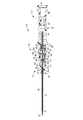
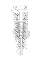
- the longitudinal cross-sectional view which shows the needle
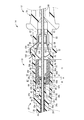
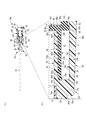
- FIG. 3 is an enlarged view showing a single product before assembly to the needle hub.
- the longitudinal cross-sectional view which expands and shows the state which inserted the male connector with respect to the needle assembly with a valve shown by FIG. (A) is a longitudinal cross-sectional view which shows another aspect in the needle assembly with a valve shown by FIG.
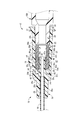
- FIG. 5 is an enlarged view showing a single product before assembly to the needle hub.
- (A) is a longitudinal cross-sectional view which shows another aspect in the needle assembly with a valve shown by FIG. 5, Comprising: (b) is a principal part enlarged view of (a).
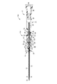
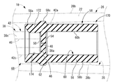
- the longitudinal cross-sectional view which expands and shows the single item state of the valve member which comprises the needle assembly with a valve as another aspect of this invention.
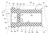
- the longitudinal cross-sectional view which expands and shows the single item state of the valve member which comprises the needle assembly with a valve as another aspect of this invention.
- FIG. 1 shows an outer needle 10 as a first embodiment of a valved needle assembly according to the present invention.
- the outer needle 10 is configured as an indwelling needle assembly 14 by inserting the inner needle 12, and after the indwelling needle assembly 14 is punctured into the skin of the patient.
- the inner needle 12 By pulling out the inner needle 12 from the outer needle 10, the outer needle 10 is inserted percutaneously into the patient's blood vessel and placed.
- the axial direction refers to the horizontal direction in FIG. 1 that is the central axis direction of the outer needle 10.
- the distal end side refers to the left side in FIG. 1 that is the side that punctures the patient, while the proximal end side refers to the right side in FIG. 1 that is the side that the user holds.
- the outer needle 10 includes an outer needle body 16 as a hollow needle and an outer needle hub 18 as a needle hub.
- the outer needle main body 16 of the present embodiment is a hollow needle formed of a soft synthetic resin and has flexibility.
- the proximal end portion of the outer needle main body 16 is inserted from the distal end side of the outer needle hub 18, and the outer needle main body 16 is fixedly supported by the outer needle hub 18.
- the inner diameter of the outer needle main body 16 is slightly larger than the outer diameter of the inner needle main body 72 of the inner needle 12 described later.
- the outer needle hub 18 has a substantially cylindrical shape as a whole, and is formed of a hard synthetic resin.
- the outer needle hub 18 has a substantially stepped cylindrical shape.
- the distal end side is a small diameter cylindrical portion 20, while the proximal end side is a large diameter cylindrical portion 22.
- the small-diameter cylindrical portion 20 is smaller in both inner diameter and outer diameter than the large-diameter cylindrical portion 22, and the small-diameter cylindrical portion 20 and the large-diameter cylindrical portion 22 have an annular shape that expands in the radial direction. They are connected by an intermediate wall portion 24.
- the proximal end portion of the outer needle main body 16 is inserted into the small-diameter cylindrical portion 20 of the outer needle hub 18 and is fixed by being subjected to a treatment such as adhesion as necessary.
- the outer peripheral surface 26 of the outer needle hub 18 includes an outer peripheral surface 26a of the small-diameter cylindrical portion 20, an outer peripheral surface 26b of the large-diameter cylindrical portion 22, and a distal end side end surface 26c of the intermediate wall portion 24.
- the inner peripheral surface 28 of the outer needle hub 18 includes an inner peripheral surface 28 a of the small diameter cylindrical portion 20, an inner peripheral surface 28 b of the large diameter cylindrical portion 22, and a proximal end side end surface 28 c of the intermediate wall portion 24. .
- the outer peripheral surface 26b and the inner peripheral surface 28b of the large-diameter cylindrical portion 22 have a tapered surface shape in which the outer diameter dimension and the inner diameter dimension gradually increase toward the proximal end as a whole.
- the inner peripheral surface 28b of the large-diameter cylindrical portion 22 has a substantially constant inner diameter dimension from the axial center portion to the distal end side, while the proximal end side from the axial center portion has an inner diameter dimension toward the proximal end side. Is gradually growing.
- the outer peripheral surface 26 (26b) of the proximal end side opening 30 of the outer needle hub 18 is provided with a flange portion 32 that protrudes to the outer peripheral side.
- the flange portion 32 has a substantially annular shape extending over substantially the entire circumference in the circumferential direction, and a male screw is formed on the outer peripheral surface. Accordingly, a luer lock type male connector can be connected to the proximal end side opening 30 of the outer needle hub 18.
- An engagement groove 34 extending in the axial direction is formed on a part of the circumference of the flange portion 32 (upward in FIGS. 2 and 3).
- an operation projecting piece 36 that protrudes to the outer peripheral side is provided on the outer peripheral surface 26 b.
- the operation projecting piece 36 has a predetermined circumferential dimension, and in this embodiment, is formed on a part of the circumference (upward in FIG. 1).
- a concave groove 37 is formed on the inner peripheral surface 28 b so as to open to the inner peripheral side and extend in the axial direction.
- the concave groove 37 has a circumferential dimension that is less than one circumference in the circumferential direction, and one or a plurality of the concave grooves 37 on the inner peripheral surface 28b of the large-diameter cylindrical portion 22 have an appropriate separation distance. It is formed with.
- the axial dimension of the concave groove 37 can be set according to, for example, the axial movement distance of a valve member 44 described later.
- a cylindrical protrusion as a cylindrical protrusion protruding from the distal end side toward the proximal end side on the proximal end surface 28 c of the intermediate wall portion 24 inside the outer needle hub 18.
- the portion 38 is integrally formed with the outer needle hub 18.
- the said cylindrical protrusion 38 is provided in the center of the intermediate wall part 24, and is provided with the center hole 40 penetrated to an axial direction. That is, the center hole 40 passes through the intermediate wall portion 24 and the cylindrical protrusion 38, and the front end side of the center hole 40 opens to the front end side end surface 26 c of the intermediate wall portion 24.
- the inner hole of the cylinder part 20 is mutually connected.
- the base end side of the center hole 40 opens to the protruding end surface (base end side end face) of the cylindrical protrusion 38, and the center hole 40 and the inner hole of the large-diameter cylindrical portion 22 communicate with each other.
- the inner hole of the small diameter cylindrical portion 20 and the inner hole of the large diameter cylindrical portion 22 are communicated with each other via the center hole 40 of the cylindrical protrusion 38.
- the inner diameter of the cylindrical protrusion 38 (center hole 40) is substantially constant in the axial direction, and is slightly larger than the inner needle main body 72 of the inner needle 12 described later.
- the inner diameter of the needle body 16 is substantially equal.
- the outer peripheral surface 42 of the cylindrical protrusion 38 has an outer diameter dimension so that the outer peripheral surface 42a of the axial base end portion (protruding front end portion) 38a can easily push open a slit 48 described later. It is made into the taper surface shape which becomes a small diameter gradually toward an end side.
- the outer peripheral surface 42a of the projecting tip portion 38a of the cylindrical projection 38 is formed by a tapered inclined surface that gradually becomes smaller in diameter toward the projecting tip side (the central valve portion 46 side of a valve member 44 described later).
- the outer peripheral surface 42b of the axial front end portion (protruding base end portion) 38b has a tapered surface shape whose outer diameter dimension gradually increases toward the front end side.
- a straight portion 38c in which the outer diameter of the outer peripheral surface 42c is substantially constant is provided in the axially intermediate portion over substantially the entire length thereof.
- the axial tip portion 38b is more cylindrical than the axial intermediate portion (straight portion) 38c.
- the peripheral wall of the protrusion 38 is formed thick.
- a valve member 44 is incorporated in the outer needle hub 18 having the above structure.
- the valve member 44 has a generally sleeve shape (substantially cylindrical shape) as a whole, and is formed of an elastic body such as a rubber such as silicon rubber or isoprene rubber, or an elastomer.
- the valve member 44 includes a central valve portion 46 having a substantially disc shape at an axially intermediate portion.
- the central valve portion 46 has a disk shape having a substantially constant thickness dimension, and a slit 48 penetrating in the thickness direction is formed in the central portion.
- the slit 48 of the present embodiment is a single character extending in the front and back direction in FIG. 1, but may be a cross shape or a radial extending from the center in a plurality of directions (for example, three directions). It should be noted that the radial dimension of the slit 48 (the dimension in the front and back direction in FIG. 1) is smaller than the inner diameter dimension of the distal end side cylindrical portion 52 and the proximal end side cylindrical portion 56 described later.
- a substantially cylindrical distal end side cylindrical portion 52 extending from the outer peripheral portion of the distal end side end surface 50 toward the distal end side, that is, the outer needle main body 16 side, and a proximal end side end surface 54
- a substantially cylindrical base end side cylindrical portion 56 extending from the outer peripheral portion toward the base end side, that is, toward the base end side opening 30 is provided.
- a substantially sleeve-like valve member 44 is configured including the distal end side cylindrical portion 52, the proximal end side cylindrical portion 56, and the central valve portion 46.
- the outer peripheral surface 58 of the valve member 44 includes the outer peripheral surface 58a of the distal end side cylindrical portion 52, the outer peripheral surface 58b of the proximal end side cylindrical portion 56, and the outer peripheral surface 58c of the central valve portion 46.
- the inner peripheral surface 60 of the valve member 44 is configured to include an inner peripheral surface 60 a of the distal end side cylindrical portion 52 and an inner peripheral surface 60 b of the proximal end side cylindrical portion 56.
- the inner diameter dimension and the outer diameter dimension of the distal end side cylindrical portion 52 are substantially constant in the axial direction, and the distal end side cylindrical portion 52 extends substantially straight in the axial direction. It is said that.
- the inner diameter dimension and the outer diameter dimension of the base end side cylindrical portion 56 are also substantially constant in the axial direction, and the base end side cylindrical portion 56 is also formed in a substantially cylindrical shape that extends substantially straight in the axial direction.
- the inner diameter dimension of the distal end side cylindrical portion 52 and the inner diameter dimension of the proximal end side cylindrical portion 56 are made substantially equal, and the outer diameter dimension of the distal end side tubular portion 52 and the proximal end side thereof.
- the outer diameter of the cylindrical portion 56 is substantially equal.
- the outer diameter dimensions of the distal end side cylindrical section 52 and the proximal end side cylindrical section 56 are slightly smaller than the inner diameter dimension of the large diameter cylindrical section 22 in the outer needle hub 18.
- the inner diameter dimension of the distal end side cylindrical part 52 and the proximal end side cylindrical part 56 is substantially equal to the maximum outer diameter dimension of the cylindrical protrusion 38 in the outer needle hub 18.
- the inner diameter dimension of 52 and the base end side cylindrical part 56 is made larger than the outer diameter dimension over substantially the entire cylindrical protrusion 38.
- an outer peripheral guide protrusion 62 that protrudes to the outer peripheral side is formed at the outer peripheral end of the central valve portion 46.
- the outer circumferential guide protrusion 62 is formed in a substantially annular shape continuously extending over the entire circumference in the circumferential direction, and the outer diameter dimension thereof is the outer diameter of the distal end side cylindrical portion 52 or the proximal end side cylindrical portion 56. It is larger than the dimensions.
- the outer peripheral surface 58 c of the central valve portion 46 is constituted by the outer peripheral surface of the outer peripheral guide protrusion 62.
- the outer peripheral guide protrusion 62 is formed to protrude to the outer peripheral side with respect to the outer peripheral surface 58 of the valve member 44.
- the outer diameter of the outer peripheral guide projection 62 on the inner peripheral surface 28 b of the outer diameter hub portion 18 of the outer needle hub 18 is the same as that of the valve member 44 before being assembled to the outer needle hub 18.
- the inner diameter dimension is set to be larger than the inner diameter dimension of the portion that is substantially constant.
- the axial dimension of the distal end side cylindrical part 52 and the proximal end side cylindrical part 56 is not limited in any way, the axial dimension B (see FIG. 3) of the distal end side cylindrical part 52 is the central valve. It is preferable that the dimension is larger than the axial dimension A (see FIG. 3) of the portion 46. Further, the maximum dimension of the axial dimension B is such that the distal end of the distal tubular portion 52 is on the inner surface (proximal end surface 28c) of the intermediate wall portion 24 of the outer needle hub 18 even when the valve member 44 is moved forward. It is desirable to set so that it does not hit. Furthermore, it is preferable that the axial dimension C (see FIG.
- the axial dimension from the proximal end side opening 30 to the proximal end surface of the proximal end tubular portion 56 is the same as the outer needle hub 18. It can be set according to the insertion length of the male connector 108 or the like to be inserted. For example, when adopting an ISO standard male connector, when the male connector 108 is inserted from the proximal end side opening 30 to 7.5 mm, the central valve portion 46 moves to the cylindrical projection 38 side and slits.
- the axial dimension from the base end side opening 30 to the base end side end surface of the base end side cylindrical portion 56 can be set to about 4 to 6 mm, for example, so that 48 is opened.
- annular seal projection 64 projecting toward the inner peripheral side is provided on the inner peripheral surface 60a of the distal end portion of the distal end side cylindrical portion 52.
- the annular seal protrusion 64 is formed continuously over the entire circumference in the circumferential direction, and the distal end side end surface is a tapered surface inclined toward the proximal end side toward the inner peripheral side.
- the end side end surface is a flat surface substantially perpendicular to the axial direction. That is, the inner diameter dimension of the distal end side cylindrical portion 52 is reduced at the site where the annular seal protrusion 64 is formed. Therefore, the inner peripheral surface 60a of the distal end side cylindrical portion 52 is configured to include the inner peripheral surface 66 of the annular seal protrusion 64 having a smaller inner diameter.
- the inner diameter dimension of the annular seal protrusion 64 is the outer diameter of the straight portion 38 c in the cylindrical protrusion 38 of the outer needle hub 18. It is about the same or slightly smaller than the dimensions.
- the valve member 44 having such a structure is incorporated in the outer needle hub 18 with the outer needle main body 16 supported at the tip, that is, in the large-diameter cylindrical portion 22, so that the outer needle 10 of the present embodiment is configured.
- the protruding tip of the cylindrical projection 38 in the outer needle hub 18 is inserted from the tip side of the valve member 44, and the protruding tip surface of the cylindrical projection 38 and the tip side of the central valve 46 in the valve member 44
- the end surfaces 50 are in contact with each other. That is, the cylindrical projection 38 and the central valve portion 46 are opposed to each other in the axial direction, and the slit 48 is formed in the central valve portion 46 at a position facing the cylindrical projection 38 in the axial direction.
- the outer diameter of the outer peripheral guide projection 62 of the valve member 44 in the single product state is larger than the inner diameter of the portion of the inner peripheral surface 28b of the large diameter cylindrical portion 22 where the inner diameter is substantially constant. For this reason, the valve member 44 is incorporated into the large-diameter cylindrical portion 22 so that the outer peripheral guide protrusion 62 is compressed radially inward.
- the outer diameter dimension of the valve member 44 other than the position where the outer peripheral guide protrusion 62 is formed is slightly smaller than the inner diameter dimension of the large-diameter cylindrical portion 22, so Between the radial direction with respect to the diameter cylindrical part 22, an annular gap is formed on both axial sides sandwiching the outer peripheral guide projection 62 (that is, the outer peripheral side of the distal end side cylindrical part 52 and the proximal end side cylindrical part 56). Is formed.
- the concave groove 37 in the inner peripheral surface 28 (28b) of the outer needle hub 18 and the outer peripheral guide protrusion 62 in the valve member 44 are provided at a position where they overlap in the axial direction. That is, the outer peripheral guide protrusion 62 of the valve member 44 is compressed to the inner peripheral side by a portion that is out of the concave groove 37 in the inner peripheral surface 28b of the large diameter cylindrical portion 22 in the circumferential direction.
- the outer peripheral surface 58c of the outer peripheral guide protrusion 62 and the inner peripheral surface 28b (groove bottom surface of the concave groove 37) of the large diameter cylindrical portion 22 are not in contact with each other.
- a tunnel-shaped gap 67 is formed by covering the opening of the concave groove 37 with the outer peripheral guide projection 62 between 58c and 28b. Therefore, it is formed on the distal end side of the outer circumferential guide projection 62 and is formed on the proximal end side of the outer circumferential guide projection 62 and the gap between the distal tubular portion 52 and the large diameter tubular portion 22 in the radial direction.
- the gap between the base end side cylindrical portion 56 and the large diameter cylindrical portion 22 in the radial direction communicates with each other through the concave groove 37 (gap 67). That is, the concave groove 37 (gap 67) forms an air vent passage for releasing air in a space 68 (described later) on the distal end side of the valve member 44 when the valve member 44 moves toward the distal end side. Yes.
- valve member 44 is compressed to the inner peripheral side by the large-diameter cylindrical portion 22 at the formation position of the outer peripheral guide protruding portion 62, so that the central valve portion 46 positioned on the inner peripheral side of the outer peripheral guide protruding portion 62.
- the slit 48 provided in is stably closed.
- the outer needle hub 18 abuts against the inner peripheral surface 28b of the large-diameter cylindrical portion 22 and uses the contact reaction force to exert a compressive force in the closing direction on the slit 48.
- the protrusion is configured by the outer peripheral guide protrusion 62.
- the annular seal protrusion 64 provided at the tip of the valve member 44 is positioned on the outer peripheral side of the cylindrical protrusion 38 in the outer needle hub 18.
- the annular seal protrusion 64 is located on the protruding distal end side (axial base end side) of the straight portion 38 c formed in the axially intermediate portion of the cylindrical protrusion 38.
- the inner diameter dimension of the annular seal protrusion 64 in the valve member 44 in the single product state is smaller than the outer diameter dimension of the straight portion 38c in the cylindrical protrusion 38, the valve member 44, the outer needle hub 18, and the like.
- the annular seal protrusion 64 is in contact with the outer peripheral surface 42c of the straight portion 38c of the cylindrical protrusion 38 over the entire periphery, and is pushed and spread outward by the cylindrical protrusion 38. So that it is compressed.
- the annular seal projection 64 is externally fitted in an expanded state in which the annular seal projection 64 is pushed and expanded to the outer circumferential side with respect to the cylindrical projection 38, and the cylindrical projection 38 is
- the inner peripheral surface 66 of the annular seal protrusion 64 and the outer peripheral surface 42c of the straight portion 38c are in close contact with each other. Therefore, in this embodiment, the tightening fitting portion that is externally fitted in the expanded state that is pushed and expanded with respect to the cylindrical projection 38 is constituted by the annular seal projection 64.
- the space between the inner peripheral surface 66 of the annular seal protrusion 64 and the outer peripheral surface 42c of the straight portion 38c in the cylindrical protrusion 38 is liquid-tightly sealed over the entire periphery.
- the inner peripheral surface 66 of the portion 64 and the outer peripheral surface 42c of the straight portion 38c in the cylindrical projection 38 are respectively annular sealing surfaces.
- annular seal protrusion 64 positioned at the tip of the valve member 44 is positioned in the vicinity of the protrusion tip of the cylindrical protrusion 38, so that the cylindrical protrusion 38 is located closer to the tip than the valve member 44.
- a substantially annular space 68 is formed on the outer peripheral side of the protruding proximal end portion with a predetermined axial dimension.
- the outer needle 10 of this embodiment having such a structure is used as an indwelling needle assembly 14 in combination with the inner needle 12 as shown in FIGS.
- the inner needle 12 has an inner needle body 72 having a sharp needle tip 70 at the tip, an inner needle hub 74 attached to the proximal end of the inner needle body 72, and is movable in the axial direction with respect to the inner needle body 72. And a needle point protector 76 attached thereto.
- the inner needle main body 72 is a hollow needle and is formed from a known material such as stainless steel, aluminum, titanium, or an alloy thereof.
- the needle tip 70 provided at the distal end of the inner needle main body 72 is formed with an inclined surface that is inclined with respect to the axial direction, and can puncture a living body easily and with low stimulation.
- a large-diameter portion 78 having a large outer diameter is formed on the outer peripheral surface of the distal end portion of the inner needle main body 72.
- the large-diameter portion 78 may be formed over the entire circumference in the circumferential direction by, for example, manufacturing the inner needle main body 72 by centerless processing, or the inner needle main body 72 is crushed. Thereby, a pair of large diameter parts 78 and 78 may be formed.
- the inner needle main body 72 may be a solid needle.
- the inner needle hub 74 attached to the proximal end of the inner needle main body 72 has a substantially cylindrical shape as a whole and is integrally formed of a hard synthetic resin.
- the inner needle hub 74 has a double cylinder structure in which axial intermediate portions are inserted and removed from each other, and the proximal end of the inner needle main body 72 is inserted into the fixed cylinder portion 80 which is an inner cylinder.
- the inner needle main body 72 is fixedly supported with respect to the inner needle hub 74 by performing a treatment such as adhesion as necessary.
- the accommodating cylinder part 82 extends on the distal end side
- the connecting cylinder part 84 extends on the proximal end side.
- a cutout 86 that opens to the front end side is formed at a part of the circumference (upward in FIGS. 2 and 3) at the front end of the accommodating cylinder portion 82.
- an inner needle cap 88 is removably assembled to the proximal end side opening of the connecting tube portion 84.
- the inner needle cap 88 is a substantially stepped cylindrical synthetic resin member provided with a step portion at an axially intermediate portion.
- a ventilation filter 90 is provided inside the inner needle cap 88, and the ventilation filter 90 has a property of allowing gas to pass therethrough but blocking liquid.
- the needle tip protector 76 provided in the inner needle 12 includes a proximal end wall portion 94 having an insertion hole 92 at the center at the proximal end, and the inner diameter dimension of the insertion hole 92 is a large diameter in the inner needle main body 72. It is smaller than the outer diameter of the portion 78 and larger than the outer diameter of the portion other than the large diameter portion 78 in the inner needle main body 72. Then, a pair of arm pieces 96 and 98 extend from the end edge portions on both sides (both sides in the vertical direction in FIGS. 2 and 3) sandwiching the insertion hole 92 of the base end wall portion 94 on the distal end side.
- the pair of arm pieces 96, 98 has elastic pieces 100, 102 that are easily elastically deformable in the radial direction at the distal ends. Further, in one arm piece 96 (upper in FIGS. 2 and 3), the proximal end side of the arm piece 96 protrudes to the outer peripheral side and bends at the protruding tip (outer peripheral side end portion). An engagement piece 104 extending to the side extends, and an engagement claw portion 106 that bends to the inner peripheral side is formed at the tip of the engagement piece 104.
- the proximal end of the inner needle main body 72 having the above structure is fixed to the inner needle hub 74, and the needle tip protector 76 is externally attached to the inner needle main body 72, whereby the inner needle 12 of the present embodiment. Is configured.
- the indwelling needle assembly 14 of this embodiment is configured by inserting the inner needle 12 through the outer needle 10.
- the needle tip protector 76 through which the inner needle main body 72 is inserted is accommodated in the accommodating cylinder portion 82 of the inner needle hub 74, and the inner needle main body 72 extending to the distal end side is open to the proximal end side of the outer needle 10. It is inserted from the portion 30, penetrates the valve member 44 through a slit 48 provided in the central valve portion 46 of the valve member 44, and is inserted from the proximal end side toward the distal end side with respect to the outer needle 10.
- the elastic pieces 100 and 102 are elastically deformed outward by the inner needle main body 72. That is, an urging force based on a restoring deformation toward the inner peripheral side is exerted on the elastic pieces 100 and 102, and the deformation of the elastic pieces 100 and 102 toward the inner peripheral side based on the urging force is caused by the inner needle main body 72. It is regulated by contacting with.
- the engagement piece 104 extending from the arm piece 96 extends to the outer peripheral side through a notch 86 provided in the housing cylinder portion 82, and is provided in the flange portion 32 of the proximal end side opening 30 of the outer needle hub 18.
- the engagement claw portion 106 provided at the tip of the engagement piece 104 and the flange portion 32 are engaged with each other by being inserted into the engagement groove 34.
- the needle tip protector 76 and the outer needle hub 18 are connected to each other in the assembled state of the outer needle 10 and the inner needle 12.
- the indwelling needle assembly 14 having the above structure is punctured into the patient's skin in a state where the outer needle 10 and the inner needle 12 are combined as shown in FIGS. By pulling out, the outer needle 10 is percutaneously placed in the blood vessel of the patient in the state shown in FIG.
- the elastic pieces 100 and 102 are moved to the inner peripheral side according to the urging force.
- the elastic pieces 100 and 102 are moved on the needle axis of the inner needle main body 72, and the needle tip 70 of the inner needle main body 72 is covered and protected by the elastic pieces 100 and 102.
- the movement of the inner needle main body 72 toward the distal end side with respect to the needle tip protector 76 after the inner needle 12 is pulled out can be restricted.
- the needle tip protector 76 of the present embodiment the needle tip 70 of the inner needle main body 72 is protected by the needle tip protector 76 along with the withdrawal of the inner needle 12 from the outer needle 10, and the needle tip protector 76 and the outer The connection with the needle hub 18 can also be released.
- the inner needle 12 can be detached from the outer needle 10 in a state where the needle tip 70 of the inner needle main body 72 is protected by the needle tip protector 76.
- the wall portions on both sides of the slit 48 in the central valve portion 46 are deformed so as to be bent toward the base end side, and the distal end side surface 50 of the central valve portion 46 is the outer peripheral surface of the straight portion 38c in the cylindrical projection 38. It comes in contact with 42c in close contact.
- the slit 48 is opened, and the inside of the outer needle body 16 and the inside of the male connector 108 are communicated with each other through the inside of the proximal end portion of the outer needle hub 18, that is, the inside of the valve member 44. Infusion, blood transfusion, blood collection, and the like can be performed.
- the male connector 108 is brought into direct contact with the proximal end side tubular portion 56 of the valve member 44 so that the valve member 44 is pushed in.
- the proximal end of the proximal end side tubular portion is used. It is good also as a structure which provides the cylindrical pushing element comprised by another member in the side, and moves a valve member to the front end side indirectly via the said pushing element.
- the outer peripheral guide projection 62 provided on the outer peripheral surface 58 of the valve member 44 contacts the inner peripheral surface 28b of the outer needle hub 18 (large diameter cylindrical portion 22).
- the valve member 44 moves to the tip side while being guided in contact therewith.
- the inner peripheral surface 28b of the large-diameter cylindrical portion 22 has a substantially constant inner diameter dimension or a tapered surface shape in which the inner diameter dimension gradually decreases toward the distal end side, and the valve member 44 Since the outer peripheral guide protrusion 62 is compressed to the inner peripheral side by the inner peripheral surface 28b before the movement toward the distal end side, the outer peripheral guide protrusion 62 even after the valve member 44 moves to the distal end side. Is compressed to the inner peripheral side by the inner peripheral surface 28b.
- the inner peripheral surface 66 of the annular seal protrusion 64 in the tubular portion 52 at the distal end side of the valve member 44 is protruded toward the projecting distal end side of the straight portion 38c in the tubular protrusion 38 (in the axial direction).
- the inner peripheral surface 66 of the annular seal protrusion 64 is in contact with and guided by the outer peripheral surface 42 of the cylindrical protrusion 38 as the male connector 108 is connected, The valve member 44 moves to the front end side.
- the annular seal protrusion 64 moves to the distal end side, and the inner peripheral surface 66 abuts in a close contact state on the protruding proximal end side (axially distal end side) of the straight portion 38c. It is like that. Therefore, in the present embodiment, the inner peripheral surface 66 of the annular seal projection 64 constituting the inner peripheral surface 60a of the distal end side cylindrical portion 52 abuts on the outer peripheral surface 42 of the cylindrical projection 38, and the valve member. A guide surface for guiding the movement of 44 is configured.
- the valve member 44 that is movable in the axial direction within the outer needle hub 18 is provided.
- the central valve portion 46 has a substantially sleeve shape in which a distal end side tubular portion 52 and a proximal end side tubular portion 56 are provided, so that excessive tilting in the outer needle hub 18 is prevented. The Therefore, the cylindrical protrusion 38 protruding to the proximal end side in the outer needle hub 18 is more securely inserted into the central valve portion 46, and the slit 48 is stably opened, that is, the inside of the male connector 108 and The outer needle body 16 can be communicated stably.
- the outer peripheral guide protrusion 62 protruding from the outer peripheral surface 58 of the valve member 44 is in contact with the inner peripheral surface 28 b of the outer needle hub 18, and the annular seal protrusion 64 provided at the tip of the valve member 44. Since the inner peripheral surface (guide surface) 66 is in contact with the outer peripheral surface 42 of the cylindrical protrusion 38, the valve member 44 is further prevented from tilting, and the valve member 44 can be more reliably moved toward the distal end side. Can be achieved.
- outer circumferential guide projection 62 can be used as a compression projection, that is, the outer circumferential guide projection 62 is compressed to the inner circumferential side by the inner circumferential surface 28 b of the outer needle hub 18. Prior to the insertion of the connector 108, the slit 48 can be maintained in a more stable closed state.
- the annular seal protrusion 64 is a tightening fitting portion and is externally fitted to the straight portion 38c of the cylindrical protrusion 38 in a compressed state
- the inner peripheral surface 66 of the annular seal protrusion 64 is provided.
- the outer peripheral surface 42c of the straight portion 38c is used as a sealing surface, and the space between the annular sealing protrusion 64 and the cylindrical protrusion 38 is liquid-tightly sealed. This prevents blood from leaking from between the cylindrical protrusion 38 and the valve member 44. For example, it is effective that blood enters and stays in the space 68 on the tip side of the valve member 44. Can be prevented.
- the inner peripheral surface 66 of the annular seal protrusion 64 is in close contact with the protruding tip side portion of the straight portion 38c of the cylindrical protrusion 38.
- the inner peripheral surface 66 of the annular seal protrusion 64 comes into close contact with the protruding proximal end portion of the straight portion 38c. That is, the gap between the annular seal projection 64 and the cylindrical projection 38 is more reliably sealed before and after the connection of the male connector 108, and the leakage of blood or chemical into the outer needle hub 18 is effective. Can be prevented.
- the distal end surface 50 of the central valve portion 46 also comes into close contact with the straight portion 38c of the cylindrical projection 38, so that the sealing performance can be further improved.
- the valve member 44 is moved when the valve member 44 is moved to the distal end side. It is also possible to move the entire 44 so as to be pushed into the space 68.
- the concave groove 37 (gap 67) provided on the inner peripheral surface 28b of the outer needle hub 18 constitutes an air vent passage for discharging the air in the space 68 on the distal end side of the valve member 44. Therefore, an increase in resistance when the male connector 108 is inserted and the valve member 44 is moved to the distal end side can be avoided.
- an outer needle 120 is shown as a second embodiment of the valve-attached needle assembly according to the present invention.
- a valve member 122 shown in FIG. 5C is assembled to the outer needle hub 18 having a structure substantially similar to that of the first embodiment.
- the outer peripheral surface 42a of the axially proximal end portion (protruding distal end portion) 38a of the cylindrical protrusion 38 has a tapered surface shape (tapered inclined surface) that gradually decreases in diameter toward the proximal end side.
- the outer diameter of the outer peripheral surface 42d is larger than the axial base end portion 38a, that is, from the axial middle portion of the cylindrical protrusion 38 to the axial front end portion (protruding base end portion).
- the straight portion 38d is substantially constant. Therefore, in this embodiment, the outer diameter dimension of the cylindrical protrusion 38 is substantially constant over substantially the entire length in the axial direction.
- the valve member 122 of the present embodiment also includes a central valve portion 124, a distal-side tubular portion 126 projecting from the central valve portion 124 toward the distal end side, and a proximal end projecting from the central valve portion 124 toward the proximal end side And a side cylindrical portion 128.
- the distal end side tubular portion 126 and the proximal end side tubular portion 128 extend substantially straight in the axial direction with a substantially constant thickness, that is, the outer periphery of the distal end side tubular portion 126.
- the surface 58a, the inner peripheral surface 60a, and the outer peripheral surface 58b and the inner peripheral surface 60b of the proximal end side cylindrical portion 128 extend in the length direction (axial direction) with substantially constant diameter dimensions, respectively.
- the axial dimension of the distal cylindrical portion 126 is made substantially equal to the axial dimension of the cylindrical projection 38 so that the distal cylindrical portion 126 covers the cylindrical projection 38 to the distal end.
- the distal end surface 129 of the distal end side tubular portion 126 is connected to the intermediate wall of the outer needle hub 18.
- the base 24 is in contact with the proximal end surface 28c of the portion 24 in the axial direction.
- the distal end surface 129 of the distal end side tubular portion 126 and the proximal end side end surface 28c of the intermediate wall portion 24 may be fixed to each other or may not be fixed. However, the distal end surface 129 of the distal end side tubular portion 126 and the proximal end side end surface 28c of the intermediate wall portion 24 may not contact each other.
- a substantially annular outer peripheral guide projection 62 protruding outward is formed at the outer peripheral end of the central valve portion 124.
- the outer peripheral guide projection 62 is compressed to the inner peripheral side by the inner peripheral surface 28b of the outer needle hub 18 (large diameter cylindrical portion 22) by assembling the valve member 122 to the outer needle hub 18. This prevents the valve member 122 from being inclined with respect to the outer needle hub 18, and the slit 48 is stably closed. Therefore, also in this embodiment, the outer circumferential guide projection 62 constitutes a compression projection that exerts a compression force in the closing direction on the slit 48.
- the proximal end side cylindrical portion 128 has an inner diameter dimension larger than the outer diameter dimension of the cylindrical protrusion 38 (straight portion 38d) in the outer needle hub 18.
- the outer diameter dimension is smaller than the inner diameter dimension of the large-diameter cylindrical portion 22 in the outer needle hub 18, and the radial direction distance between the proximal-side cylindrical portion 128 and the large-diameter cylindrical portion 22 of the outer needle hub 18. Is formed with a substantially annular gap.
- the inner diameter dimension of the front end side cylindrical portion 126 of the present embodiment is substantially equal to or slightly larger than the outer diameter dimension of the cylindrical protrusion 38 (straight portion 38d).
- the outer diameter dimension of the distal end side cylindrical portion 126 is not limited in any way, but the distal end side cylindrical portion 126 is easily elastic when the distal end side cylindrical portion 126 moves to the distal end side of a valve member 122 described later.
- the distal end side cylindrical portion 126 is thinner than the central valve portion 124, the proximal end side cylindrical portion 128, and a tapered portion 130 described later. ing.
- the outer diameter dimension of the distal end side cylindrical part 126 is smaller than the outer diameter dimension of the central valve part 124 and the proximal end side cylindrical part 128, A substantially annular space 68 is formed between the large diameter cylindrical portion 22 and the radial direction.
- the proximal end portion of the distal end side cylindrical portion 126 and the outer peripheral portion of the central valve portion 124 are connected by a substantially cylindrical tapered portion 130 that gradually becomes smaller in diameter toward the distal end side. That is, the outer peripheral surface 58d of the tapered portion 130 that connects the outer peripheral surface 58a of the front end side cylindrical portion 126 and the outer peripheral surface 58c of the central valve portion 124 (outer peripheral guide projection 62) is an outer diameter dimension toward the front end side. Is a tapered surface that gradually becomes smaller in diameter.
- the inner peripheral surface 60c of the tapered portion 130 is a tapered surface that gradually decreases in diameter toward the distal end side, and the inner peripheral surface 60c of the tapered portion 130 and the distal end side end surface 50 of the central valve portion 124, Are connected by an annular surface extending substantially parallel to the axial direction.
- the tapered portion 130 has an outer peripheral surface 58d and an inner peripheral surface 60c, both of which are tapered surfaces whose outer diameter size and inner diameter size gradually decrease toward the distal end side.
- the diameter gradually decreases from the tip toward the distal end tubular portion 126, and the thickness dimension is substantially constant.
- the outer peripheral surface 58d is a tapered surface and the inner diameter of the inner peripheral surface is substantially constant, the thickness of the portion closer to the proximal end than the tapered portion 130 is on the proximal end side. It is connected to the central valve portion 124 while gradually becoming larger.
- the outer peripheral surface 58 of the valve member 122 includes the outer peripheral surface 58a of the distal end side cylindrical portion 126, the outer peripheral surface 58b of the proximal end side cylindrical portion 128, and the central valve portion 124 (the outer peripheral guide protrusion). 62) and an outer peripheral surface 58d of the tapered portion 130.
- the inner peripheral surface 60 of the valve member 122 includes an inner peripheral surface 60a of the distal end side cylindrical portion 126, an inner peripheral surface 60b of the proximal end side cylindrical portion 128, and an inner peripheral surface 60c of the tapered portion 130. It is comprised including.
- the outer peripheral surface 58d of the tapered portion 130 and the tip side surface of the outer peripheral guide projection 62 have substantially the same inclination angle with respect to the axial direction, and these are one flat surface. It is formed as a tapered surface.
- the valve member 122 is moved to the distal end side while the outer peripheral guide projection 62 is compressed to the inner peripheral side, such as when the valve member 122 is assembled to the outer needle hub 18 or when the male connector 108 is inserted.
- the friction between the outer peripheral guide projection 62 and the inner peripheral surface 28b of the outer needle hub 18 (large-diameter cylindrical portion 22) is avoided, and the valve member 122 can be easily moved to the distal end side. Can be realized.
- the connection portion between the distal end side cylindrical portion 126 and the tapered portion 130 that is, the proximal end on the inner peripheral surface 60 a of the distal end side cylindrical portion 126, or the tapered portion 130.
- An annular seal protrusion 132 that protrudes toward the inner peripheral side is formed at the tip of the inner peripheral surface 60c.
- the annular seal protrusion 132 is formed with a substantially semicircular cross section, and the inner diameter of the valve member 122 at the top of the annular seal protrusion 132 in a single product state before being assembled to the outer needle hub 18. The dimension is made smaller than the outer diameter dimension of the straight portion 38d of the cylindrical protrusion 38 (see FIG.
- valve member 122 is assembled to the outer needle hub 18, so that the valve member 122 is pushed outward at the formation position of the annular seal protrusion 132, and the annular seal protrusion 132 is elastically restored. It is in close contact with the outer peripheral surface 42d of the straight portion 38d by force. That is, also in this embodiment, the tightening fitting portion is constituted by the annular seal protrusion 132, and the inner peripheral surface 134 of the annular seal protrusion (tightening fitting portion) 132 is used as a seal surface. Yes.
- a guide surface that guides the movement of the valve member 122 toward the distal end side is configured by the inner peripheral surface 134 of the annular seal protrusion 132.
- the distal end side cylindrical portion 126 is grasped as a guide surface that guides the movement of the valve member 122 toward the distal end side.
- the inner diameter dimension of the distal cylindrical portion 126 excluding the annular seal protrusion 132 substantially equal to the outer diameter dimension of the straight portion 38d of the cylindrical protrusion 38?
- the inner peripheral surface 60a of the distal end side cylindrical portion 126 excluding the annular seal protrusion 132 and the outer peripheral surface 42d of the straight portion 38d are formed. It makes contact with zero touch over substantially the entire length in the axial direction, or is slightly separated.
- the seal surface is configured only by the inner peripheral surface 134 of the annular seal protrusion 132 on the inner peripheral surface 60a of the distal end side tubular portion 126, and the portion that does not constitute the seal surface is the seal surface. Is formed with an axial dimension longer than that of the portion constituting the.
- the inner peripheral surface 60c of the tapered portion 130 is a tapered surface whose inner diameter dimension gradually decreases toward the distal end side, so that the tapered portion 130 is mounted in the state where the valve member 122 is assembled to the outer needle hub 18.
- An annular gap 136 is formed on the inner peripheral side, that is, between the tapered portion 130 and the cylindrical protrusion 38 in the radial direction. In short, the annular gap 136 is formed in a region surrounded by the tapered portion 130, the cylindrical projection 38, and the central valve portion 124. In the present embodiment, when the valve member 122 and the outer needle hub 18 are assembled, the protruding front end surface of the cylindrical protrusion 38 and the front end side end surface 50 of the central valve portion 124 are in contact with each other.
- the gap 136 and the space (center hole 40) inside the cylindrical protrusion 38 are not communicated with each other, but the protruding front end surface of the cylindrical protruding portion 38 and the front end side end surface 50 of the central valve portion 124 are mutually connected.
- the gap 136 and the space (center hole 40) inside the cylindrical protrusion 38 may communicate with each other without contacting.
- the outer needle main body 16 is moved.
- the valve member 122 is assembled
- an annular seal protrusion 132 that is in close contact with the outer peripheral surface 42 (42d) of the cylindrical protrusion 38 (straight portion 38d) is formed only at the base end portion of the distal end side cylindrical portion 126.
- the outer needle 120 is indwelled on the patient's skin by puncturing the indwelling needle assembly 138 into the skin and removing the inner needle 12. Then, as shown in FIG. 7, by inserting the male connector 108 such as a syringe from the proximal end side opening 30 of the outer needle 120, the valve member 122 is pushed to the distal end side by the distal end of the male connector 108, The slit 48 is pushed open by the cylindrical protrusion 38, and infusion, blood transfusion, blood collection, and the like can be performed.
- the male connector 108 such as a syringe
- the wall portions on both sides of the slit 48 in the central valve portion 124 are deformed so as to be bent toward the proximal end, and the distal end side end surface 50 of the central valve portion 124 is formed into the cylindrical protrusion 38. Are in close contact with the outer peripheral surface 42d of the straight portion 38d.
- the distal end surface 129 of the distal end side cylindrical portion 126 is located on the intermediate wall portion 24 at the time before the male connector 108 is inserted and the valve member 122 moves toward the distal end side. Since the male connector 108 is inserted and the central valve portion 124 of the valve member 122 is moved toward the distal end side, that is, toward the cylindrical projection 38, the distal end surface 28c is in contact with the proximal end surface 28c in the axial direction. The side cylindrical portion 126 is compressed between the central valve portion 124 and the intermediate wall portion 24 in the axial direction so as to be elastically deformed. Thereby, in this embodiment, as shown in FIG.
- the front end side cylindrical portion 126 undulates in the length direction, or a bellows shape, that is, peaks and valleys are alternately continuous in the axial direction.
- the axial dimension of the distal end side tubular portion 126 is shortened as compared with the state before the male connector 108 is inserted.
- the elastic deformation of the distal end side cylindrical portion 126 occurs on the distal end side of the portion that does not constitute the seal surface in the distal end side cylindrical portion 126, that is, the annular seal protrusion 132.
- the same effects as those in the first embodiment are exhibited. obtain.
- the distal end side cylindrical portion 126 covers the cylindrical projection 38 over substantially the entire length in the axial direction, the valve member 122 is more reliably inclined with respect to the outer needle hub 18. Can be prevented.
- annular gap 136 is formed between the annular seal protrusion 132 and the central valve portion 124 in the axial direction.
- the male connector 108 is inserted into the outer needle hub 18, and the wall portions on both sides of the slit 48 in the central valve portion 124 are deformed by the cylindrical projection 38 so as to be bent toward the proximal end side.
- the force accompanying the deformation is not directly applied to the annular seal protrusion 132, and the seal of the outer peripheral surface 42 of the cylindrical protrusion 38 by the annular seal protrusion 132 is stably maintained.
- the slit 48 can be stably pushed and opened by the cylindrical protrusion 38 in a state where the seal by the annular seal protrusion 132 is maintained.
- the tapered portion 130 is thicker than the distal end side tubular portion 126, and the annular seal protrusion 132 is formed at the connection portion between the tapered portion 130 and the distal end side tubular portion 126.
- the annular seal protrusion 132 is provided at a portion that is thicker than the other portions of the distal end side cylindrical portion 126 and is less likely to be elastically deformed, the distal end side cylindrical portion 126 excluding the annular seal protrusion 132 is provided. It is possible to stably maintain the seal of the outer peripheral surface 42 of the cylindrical protrusion 38 while easily causing the elastic deformation of the cylindrical protrusion 38.
- the outer periphery of the central valve portion 124 The shape of the part can be maintained stably. Therefore, it is possible to more effectively enjoy the guide action by the outer peripheral guide protrusion (compression protrusion) 62 provided on the outer peripheral portion of the central valve portion 124 and the closing action of the slit 48.
- the space 136 is a gap 136 between the tapered portion 130 and the cylindrical projection 38 in the radial direction.
- the volume of the gap 136 can be made as small as possible. Accordingly, even when air remains in the gap 136 when the valve member 122 and the outer needle hub 18 are assembled, the amount of air mixed into the patient's body through the outer needle 120 can be reduced.
- the distal end side tubular portion 126 is compressed in the axial direction and deformed. That is, when the male connector 108 is inserted, the urging force toward the base end side is exerted on the base end side cylindrical portion 128 by the elastic restoring force of the front end side cylindrical portion 126. Communication (connection) between the portion 128 and the male connector 108 can be stably maintained.
- the central valve portion 124 can be displaced to the initial position by the elastic restoring force of the distal end side tubular portion 126, so that the male connector The slit 48 can be closed with the removal of 108.
- the male connector 108 can be inserted into and removed from the outer needle (needle assembly with valve) 120 a plurality of times.
- the elastic deformation can be easily caused by making the distal end side cylindrical portion 126 thinner than the tapered portion 130, the central valve portion 124, and the proximal end side cylindrical portion 128.
- FIGS. 8A and 8B show an outer needle (needle assembly with valve) 140 as another aspect of the present embodiment. That is, in the valve member 142 in this aspect, the distal end side tubular portion 126 covers the tubular protrusion 38 to the distal end and extends to the distal end inside the outer needle hub 18 as shown in FIG.
- an annular seal protrusion 144 is provided at the distal end portion of the inner peripheral surface 60a of the distal end side cylindrical portion 126.
- the inner diameter dimension of the annular seal protrusion 144 is made smaller than the outer diameter dimension of the straight portion 38d of the cylindrical protrusion 38 (FIG. 8).
- valve member 142 is assembled to the outer needle hub 18, whereby the annular seal protrusion 144 is pushed outward by the outer peripheral surface 42 d of the straight portion 38 d, and due to its elastic restoring force.
- the straight portion 38d is brought into close contact with the outer peripheral surface 42d.
- the outer peripheral surface 42 of the cylindrical protrusion 38 abuts with the inner peripheral surface 60 a of the distal end side cylindrical portion 126 by substantially zero touch or slightly.
- the seal surface is formed by the inner peripheral surface 146 of the annular seal protrusion 144.
- the part which does not comprise a sealing surface in the internal peripheral surface 60a of the front end side cylindrical part 126 is formed with the axial direction dimension longer than the part (annular seal protrusion 144) which comprises a sealing surface. Also in this aspect, it is possible to grasp the substantially entire surface of the inner peripheral surface 60a of the distal end side tubular portion 126 as a guide surface.
- valve member 142 is not provided with the tapered portion (130), and no gap (136) is formed between the cylindrical protrusion 38 and the valve member 142.
- connection portion the base end portion of the distal end side tubular portion 126) between the distal end side tubular portion 126 and the central valve portion 124, the protruding distal end portion (axis) of the tubular protrusion 38 is provided.
- An overlapping portion 148 is provided as a connecting portion to be overlapped with the outer peripheral surface 42a of the (direction base end portion) 38a.
- the overlapping portion 148 has a tapered inclined surface 42a.
- an inclined inner surface 150 that gradually becomes smaller in diameter toward the central valve portion 124 is provided.
- the overlapping portion 148 is configured such that the thickness dimension (dimension in the direction perpendicular to the axis) gradually increases from the distal tubular portion 126 toward the central valve portion 124.
- the valve member 142 having the above-described structure is assembled to the outer needle hub 18, so that the outer peripheral surface (tapered inclined surface) 42 a of the projecting tip portion 38 a of the cylindrical projecting portion 38 and the overlapping portion 148.
- the inclined inner surfaces 150 are in contact with each other and overlapped.
- the annular projecting portion 144 is provided and the space between the tubular projecting portion 38 and the distal end side tubular portion 126 is sealed. Leakage of blood and chemicals through the space with 126 can be effectively prevented.
- the front end side cylindrical portion 126 covers the cylindrical protrusion 38 over substantially the entire length in the axial direction, and the annular seal protrusion 144 at the front end portion of the front end side cylindrical portion 126 is provided.
- the cylindrical projection 38 is sealed so as to be in close contact with the outer peripheral surface (tip-side outer peripheral surface 42e) at the distal end portion over the entire circumference.
- the distal end side tubular portion 126 is compressed in the axial direction by inserting the male connector (108) and moving the valve member 142 toward the distal end side.
- the portion that does not constitute the seal surface (the portion where the annular seal protrusion 144 is not formed) on the inner peripheral surface 60 a of the distal end side tubular portion 126 is elastic so as to wave, for example, in the axial direction. It can be deformed. That is, in this aspect, the distal end side cylindrical portion 126 is in contact with only the distal end side outer peripheral surface 42e of the cylindrical protrusion 38 in a compressed state over the entire periphery, and is connected by a male connector (108) as an external device.
- FIGS. 9A and 9B show an outer needle (needle assembly with valve) 160 as still another aspect of the present embodiment.
- the axial dimension of the distal end side cylindrical portion 126 is slightly larger than the axial dimension of the cylindrical protrusion 38.
- the distal end side tubular portion 126 covers the tubular protrusion 38 to the distal end and extends to the distal end inside the outer needle hub 18, and the distal end side tubular shape.
- the portion 126 is slightly compressed in the axial direction, and the distal end surface 129 of the distal end side tubular portion 126 and the proximal end side end surface 28c of the intermediate wall portion 24 are in close contact with each other in the axial direction.
- a sealing surface is constituted by the distal end surface 129 of the distal end side cylindrical portion 126, and blood or blood passes between the distal end side cylindrical portion 126 and the cylindrical protrusion 38 by the seal by the sealing surface. The chemical solution is prevented from leaking.
- the central valve portion 124 and the proximal end side tubular portion 128 are brought into the proximal end side due to elastic restoring deformation of the distal end side tubular portion 126.
- the outer peripheral guide projection 62 provided on the outer peripheral side of the central valve portion 124 is assembled in a compressed state with respect to the outer needle hub 18, so that the central valve portion 124 and the proximal end side tubular shape are provided. The movement of the portion 128 to the proximal end side is prevented.
- the pressing reaction force of the outer peripheral guide protrusion 62 is exerted on the inner peripheral surface 28b of the outer needle hub 18 (large diameter cylindrical portion 22), whereby the valve member 162 is positioned in the axial direction with respect to the outer needle hub 18.
- the front end side cylindrical part 126 is assembled in a state compressed in the axial direction.
- the mechanism for preventing the central valve portion 124 and the proximal end side cylindrical portion 128 from moving to the proximal end side without providing the outer periphery guiding projection 62 or even when the outer periphery guiding projection 62 is provided. May be provided separately.
- the inner peripheral surface 60a of the distal end side cylindrical portion 126 and the outer peripheral surface 42 of the cylindrical protrusion 38 may be zero-touched each other, or slightly. May be separated. Therefore, also in this aspect, it is possible to grasp the substantially entire surface of the inner peripheral surface 60a of the distal end side tubular portion 126 as a guide surface.
- a flange-like portion 164 that protrudes to the outer peripheral side is formed at the tip of the tip-side cylindrical portion 126 of this aspect, and the area of the tip-side cylindrical portion 126 on the tip surface 129 is increased.
- the projecting dimension of the flange-shaped portion 164 toward the outer peripheral side is not large enough to reach the inner peripheral surface 28b of the large-diameter cylindrical portion 22 in the outer needle hub 18, but the flange-shaped portion 164
- the outer peripheral surface may abut on the inner peripheral surface 28b of the large-diameter cylindrical portion 22, that is, the distal end surface 129 of the distal end side cylindrical portion 126 and the proximal end side end surface 28c of the intermediate wall portion 24 extend over substantially the entire surface. You may contact
- the contact area between the distal end surface 129 and the proximal end surface 28c is increased, so that the sealing effect by the distal end surface 129 of the distal tubular portion 126 is stably exhibited. Can be done.
- the distal end side cylindrical portion 126 is compressed in the axial direction, so that the inner peripheral surface 60a of the distal end side cylindrical portion 126 bulges and deforms toward the inner peripheral side and comes into close contact with the outer peripheral surface 42 of the cylindrical protrusion 38.
- the tip 60d (for example, the inner peripheral surface of the flange-like portion 164) of the inner peripheral surface 60a of the tip-side cylindrical portion 126 bulges and deforms toward the inner peripheral side, and the cylindrical protrusion 38 (38d) may be in close contact with the outer peripheral surface 42e of the tip side over the entire circumference in the circumferential direction. That is, in addition to the front end surface 129 of the front end side cylindrical portion 126, for example, a seal surface may be configured by the front end 60d of the inner peripheral surface 60a.
- the bulging deformation to the inner peripheral side of the inner peripheral surface 60a of the distal end side tubular portion 126 is not limited to the distal end 60d, and may be an axial intermediate portion or an axial proximal end portion,
- the seal surface may be constituted by the axially intermediate portion or the axially proximal end portion of the inner peripheral surface 60a.
- the distal end side tubular portion 126 is thinner than the central valve portion 124 and the proximal end side tubular portion 128, elastic deformation of the distal end side tubular portion 126 is easily caused. Can be done.
- the valve member 162 may be molded in a state where the flange-shaped portion 164 is provided at the distal end of the distal-side tubular portion 126 in the single-component state before the valve member 162 is assembled to the outer needle hub 18.
- the tubular portion 126 on the distal end side of the valve member 162 may be formed in a state extending substantially linearly in the axial direction without providing the flange-shaped portion 164, and by assembling the valve member 162 to the outer needle hub 18.
- the front end side cylindrical portion 126 may be compressed in the axial direction, and the front end side cylindrical portion 126 may be bulged and deformed to the outer peripheral side to form the flange portion 164.
- the distal end side tubular portion 126 is formed, for example, by inserting the male connector (108) and moving the valve member 162 to the distal end side. Similar to the embodiments shown in 5 to 7, it is elastically deformed so as to wave in the axial direction. That is, when the proximal end side cylindrical portion 128 is pressed to the distal end side by the male connector (108) as an external instrument, for example, a seal surface is not formed on the inner peripheral surface 60a of the distal end side cylindrical portion 126.
- the intermediate portion in the length direction of the distal end side tubular portion 126 is deformed in the radial direction, that is, it is elastically deformed so as to wave, for example, in the axial direction.
- the distal end surface 129 of the distal end side cylindrical portion 126 and the proximal end side end surface 28c of the intermediate wall portion 24 do not need to be in contact with each other, and the male connector (108 ),
- the distal end surface 129 of the distal end side tubular portion 126 and the proximal end side end surface 28c of the intermediate wall portion 24 are tightly sealed. Also good. That is, in this aspect, for example, in the initial state, the cylindrical shape is formed by the distal end 60d of the distal end side tubular portion 126 with or without the annular seal protrusion (144) as described in the aspect shown in FIG. Only the front end side outer peripheral surface 42e of the protrusion 38 may be sealed. And by inserting the male connector (108) as an external instrument, in addition to the front end side outer peripheral surface 42e, the base end side end surface 28c of the intermediate wall part 24 may be sealed.
- the valve member when the male connector is inserted into the outer needle to open the slit and then the male connector is removed from the outer needle, the valve member is not moved.
- Return means for exerting an operating force in the direction of returning to the original position may be provided.
- Such return means is not limited in any way, but for example, the valve member is returned to its original position by the elastic restoring force of the central valve portion bent toward the proximal end side as the valve member moves toward the distal end side.
- the return means may comprise a folded central valve portion.
- the male connector is temporarily removed to block communication with the hollow needle, and when the infusion is resumed, the male connector is inserted again to be hollow.
- the male connector can be connected to the outer needle a plurality of times, such as communicating the needle with the male connector.
- the entire valve member 44 has moved to the distal end side with the insertion of the male connector 108.
- at least the central valve portion has moved to the distal end side, and the slit is opened by the projection. It only has to be adapted. That is, as described in, for example, the second embodiment and Japanese Patent Application Laid-Open No. 2004-242663, the distal side tubular portion is axially moved by the movement of the central valve portion toward the distal end accompanying the insertion of the male connector. It may be compressed with. In such a case, as the male connector is removed, the distal end side tubular portion may be elastically restored and deformed so that the valve member returns to the original position, and includes the distal end side tubular portion. The return means may be configured. In addition, as described in Japanese Patent Application Laid-Open No. 2004-242663, the distal end side tubular portion of the valve member may be fixed to the inner peripheral surface of the needle hub or the outer peripheral surface of the protrusion.
- the return means for returning the valve member to the original position utilizes the elasticity of the valve member as described above, and, for example, the outer peripheral surface of the protrusion or the inner peripheral surface of the needle hub is formed into a tapered surface shape, and the valve member is tapered. You may make it return to an original position by sliding with respect to a surface.
- an elastic member such as a coil spring that exerts an urging force in a direction returning to the original position with respect to the valve member when the male connector is inserted is provided between the needle hub and the valve member. The valve member may return to the original position according to the force.
- the central valve portion of the valve member moves to the tip side with the space on the tip side or outer periphery side of the tip side cylindrical portion of the valve member as a sealed space
- the tip side or outer periphery side of the tip side cylindrical portion moves.
- the air in this space may be compressed so that a return force in the proximal direction is applied to the valve member.
- these returning means may be employed, or a plurality of returning means may be employed in combination.
- the return means is not indispensable, and after completion of the infusion, the outer needle (needle assembly with valve) may be removed together with the male connector and discarded.
- the projecting portion extending toward the proximal end inside the outer needle hub 18 has a cylindrical shape, but is not limited to such a mode. That is, the protrusion may extend in the axial direction with, for example, an arc-shaped cross section, and communicates the large diameter cylindrical portion 22 of the outer needle hub 18 and the small diameter cylindrical portion 20 (the outer needle main body 16 that is a hollow needle). If the communication hole is provided separately, the protrusion may be, for example, a long block shape. In such a case, the protrusion may have various cross-sectional shapes such as a circular cross section including an ellipse, an ellipse, and a semicircle, and a polygonal cross section.
- the protrusion may be formed in a straight shape over the entire length without providing a tapered portion on the outer peripheral surface, or may be formed in a tapered shape over the entire length without providing a straight portion. Also good. Moreover, even when a taper portion or a straight portion is provided, the formation position thereof is not limited at all, and a straight portion is provided at the axial base end portion or the axial tip portion, or in the axial middle. The portion may be provided with a tapered portion.
- the intermediate portion in the axial direction of the cylindrical protrusion 38 is the straight portions 38c and 38d over the entire length. However, the present invention is not limited to this aspect, and at least one of the intermediate portions in the axial direction.
- the part is preferably a straight part.
- the outer peripheral guide protrusion (compression protrusion) 62 and the annular seal protrusions (tightening fitting parts) 64, 132, and 144 extend continuously over the entire circumference in the circumferential direction.
- the outer peripheral guide protrusion (compression protrusion) and tightening fitting parts may be formed in the circumferential direction.
- the outer peripheral guide protrusion (compression protrusion) need not be provided at the outer peripheral end of the central valve portion, and may be provided at the distal end side cylindrical portion or the proximal end side cylindrical portion.
- annular seal protrusion does not need to be provided at the distal end portion of the distal end side tubular portion as in the first embodiment or the aspect shown in FIG. It may be provided at the proximal end portion of the distal end side tubular portion as in the embodiment (the mode shown in FIGS. 5 to 7) or at the axially intermediate portion of the distal end side tubular portion.
- the outer peripheral guide protrusions (compression protrusions) 62 protrude from the outer peripheral surface 58 of the valve members 44, 122, 142, 162 to the outer peripheral side.
- the protrusion may protrude from the inner peripheral surface of the needle hub to the inner peripheral side.
- the annular seal protrusions (tightening fitting portions) 64, 132, and 144 protrude from the inner peripheral surface 60a of the distal end side cylindrical portions 52 and 126 to the inner peripheral side toward the inner peripheral side.
- a protrusion may be provided on the outer peripheral side from the outer peripheral surface of the protrusion that protrudes toward the proximal end inside the needle hub to exhibit a sealing function or the like.
- the tightening fitting portion is configured by the annular seal protrusions 64, 132, and 144.
- the tightening fitting portion may be configured without providing the annular seal protrusion. . That is, in the valve member 170 shown in a single product state before being assembled to the outer needle hub 18 in FIG. 10, the annular seal protrusions (64, 132) as in the above embodiment are formed on the inner peripheral surface 174 of the distal end side cylindrical portion 172. 144) is not provided. Therefore, the distal end side cylindrical portion 172 is a cylindrical portion with the inner peripheral surface 174 extending substantially straight.
- the inner diameter dimension of the distal end side cylindrical portion 172 in such a single product state is smaller than the outer diameter dimension of the straight portion 38 c of the cylindrical protrusion 38 provided on the outer needle hub 18. Therefore, in the state where the valve member 170 is assembled to the outer needle hub 18, the inner peripheral surface 174 of the distal end side cylindrical portion 172 is pushed outward by the cylindrical protrusion 38 and is externally fitted in an expanded state. . In other words, the front end side cylindrical portion 172 tightens the cylindrical protrusion 38 from the outer peripheral side, and the inner peripheral surface 174 of the front end side cylindrical portion 172 is on the outer peripheral surface 42c of the straight portion 38c in the cylindrical protrusion 38.
- the sealing performance between the valve member 170 and the outer needle hub 18 is exhibited. That is, in this aspect, the fastening fitting portion is configured by the distal end side cylindrical portion 172, and the seal surface is configured by the inner peripheral surface 174 of the distal end side cylindrical portion 172. In addition, a guide surface that guides the movement of the valve member 170 toward the distal end side may be configured by the inner peripheral surface 174 of the distal end side cylindrical portion 172.
- the inner peripheral surface of the distal cylindrical portion can be a sealing surface also in the mode shown in FIG. That is, FIG. 11 shows the valve member 180 in a single product state before being assembled to the outer needle hub 18, and also in this aspect, the inner peripheral surface 184 of the distal end side cylindrical portion 182 Such annular seal protrusions (64, 132, 144) are not provided.
- a pressing protrusion 186 that protrudes to the outer peripheral side is provided at the front end portion of the outer peripheral surface 58a of the front end side cylindrical portion 182.
- the pressing protrusion 186 has an annular shape extending continuously over the entire circumference in the circumferential direction, and the outer diameter dimension in a single product state is larger than the inner diameter dimension of the outer needle hub 18.
- the sealing surface is constituted by the inner peripheral surface 184 of the distal end side cylindrical portion 182.
- a guide surface that guides the movement of the valve member 180 toward the distal end side may be configured by the inner peripheral surface 184 of the distal end side cylindrical portion 182.
- outer peripheral guide protrusions pressing protrusions, compression protrusions, annular seal protrusions, and fastening fitting parts are not essential in the present invention. That is, for example, when the outer peripheral guide protrusion, the pressing protrusion, and the compression protrusion are not provided on the outer peripheral surface of the valve member, the outer peripheral surface of the valve member having a substantially straight shape extends over the entire surface of the needle hub. It may be in contact with the inner peripheral surface or may not be in contact with the inner peripheral surface of the needle hub over the entire surface.
- the inner peripheral surface of the distal end side cylindrical portion that is substantially straight is formed over the entire surface. It may be in contact with the outer peripheral surface of the protrusion, or may not be in contact with the outer peripheral surface of the protrusion over the entire surface.
- the concave groove 37 is provided on the inner peripheral surface 28 b of the outer needle hub 18, and the air vent passage is formed by the gap 67 between the concave groove 37 and the outer peripheral guide protrusion (compression protrusion) 62.
- the air vent passage may be configured by a gap between the outer peripheral surface of the valve member and the inner peripheral surface of the needle hub at a position where the portion, the pressing protrusion, and the compression protrusion are removed in the circumferential direction.
- the air vent passage may be configured by forming the concave groove 37 on the inner peripheral surface 28b of the outer needle hub 18 as in the above embodiment, or by forming the concave groove on the outer peripheral surface of the valve member.
- it may be constituted by a through hole that penetrates the valve member in the axial direction.
- it is good also as a structure which can discharge
- an air vent passage is not essential in the present invention. If the air vent passage is not formed, the space on the distal end side and the outer peripheral side from the tubular portion on the distal end side of the valve member is a sealed region. When moving to the position, the action of the air spring is exerted, and the action of the air spring may return the valve member to the original position as the male connector is removed. That is, return means for returning the valve member to the original position may be configured by the action of the air spring in the space on the distal end side or the outer peripheral side with respect to the tubular portion on the distal end side of the valve member defined as the sealed region.
- a sleeve-like separate member that guides the axial movement of the valve member may be provided between the needle hub and the valve member in the radial direction.
- the cylindrical protrusion 38 in the above embodiment may have various cylindrical shapes such as a rectangular cylindrical shape and an elliptical cylindrical shape in addition to the illustrated circular cylindrical shape.
- the cylindrical protrusion may be any member that can open the valve member by movement.
- the cylindrical protrusion is hollow. It is also possible to employ a solid protrusion having no structure instead of the cylindrical protrusion 38.
- the outer needle (needle assembly with valve) 10 is used as the indwelling needle assembly 14 in combination with the inner needle 12, but the outer needle main body 16 is formed of a hard member, for example.
- the needle assembly with valve 10 can be used alone.
- a known valve member may be employed as a valve member that is integrally formed with the needle hub and that comes into close contact with a protrusion that extends toward the proximal end.
- a valve member as described in Japanese Patent Application Laid-Open No. 2004-242663, a straight portion formed on the inner peripheral surface of the tubular portion on the distal end side of the valve member and the axially intermediate portion of the protrusion is used. The outer peripheral surface may be contacted in close contact.
- the structure of the needle tip protector that protects the needle tip of the inner needle body is not limited in any way.
- it is not a type of safety mechanism that automatically activates the safety mechanism by pulling out the inner needle, but when the button is pressed, the inner needle body moves to the proximal end side of the inner needle hub by a coil spring, etc.
- a safety mechanism of a type in which the tip of the inner needle main body is accommodated in the inner needle hub may be employed.
- the proximal end side tubular portions 56 and 128 and the distal end side tubular portions 52 and 126 of the valve members 44, 122, 142, and 162 and the inner peripheral surface 28 b of the outer needle hub 18 are disposed.
- An annular gap is provided. The gap also serves to reduce the sliding resistance when the valve member moves in the axial direction within the needle hub, but the shape of the gap does not have to be an annular shape continuously around the entire circumference.
- an axial gap extending between the axial ribs adjacent in the circumferential direction may be provided, or the shaft may be disposed on the outer peripheral surface of the valve member.
- a plurality of axial ribs extending in the direction may be provided to provide a similar axial gap, or a valve member having an outer peripheral surface of substantially the same diameter that does not form a seal surface with the inner peripheral surface of the needle hub By doing so, there may be no gap between the needle hub and the proximal end side cylindrical portion or the distal end side cylindrical portion.
- the central valve portions 46 and 124 are almost entirely compressed in the inner diameter direction by the outer needle hub 18, but may be compressed only in the direction in which the slit is closed.
- the compression in the inner diameter direction from the needle hub to the central valve portion acts at the position before the axial movement of the valve member, thereby stabilizing the closed state of the slit, while the position after the movement
- the sealing performance between the central valve portion and the inner peripheral surface of the needle hub can be improved.
- the compression projection 62 is provided on the inner peripheral surface of the outer needle hub 18 (large-diameter cylindrical portion 22) both before and after the valve members 44, 122, 142, 162 are moved to the distal end side. Although compressed by 28b, the compression in the inner diameter direction from the needle hub to the central valve portion can be performed before or after the movement of the valve member in the axial direction.
- the inner peripheral surface of the needle hub has a tapered surface shape with a gradually decreasing inner diameter dimension toward the distal end side, and before the valve member moves to the distal end side, the compression projection is in an uncompressed state, The compression protrusion may be compressed by the inner peripheral surface of the needle hub by moving the valve member toward the distal end side.
- a mechanism for positioning the valve member at a specific position in the needle hub may be provided in order to suitably assemble the valve member in the needle hub.
- a contact protrusion that protrudes in a ring shape or partially in the circumferential direction is provided inside the needle hub, and the contact protrusion and an outer peripheral surface such as a central valve portion are provided.
- the protrusions such as the guide protrusions and the compression protrusions may be positioned in contact with each other in the axial direction.
- an engagement protrusion that protrudes in a ring shape or partially in the circumferential direction is provided inside the needle hub, while an engagement groove that extends in the circumferential direction is formed on an outer peripheral surface such as a proximal-side cylindrical portion of the valve member. They may be provided so that the engaging protrusions and the engaging groove portions are in contact with each other and positioned in the axial direction. Note that the engagement protrusion and the engagement groove may be provided opposite to each other.
- the inner needle hub and the needle tip protector are inserted into the needle hub so as to be assembled or mounted, and the distal end of the inner needle hub or the needle tip protector is a positioning cylindrical portion that comes into contact with the valve member from the base end side, Assembling the valve member in the needle hub according to the insertion length or the insertion position of the positioning cylindrical portion with respect to the needle hub by inserting the positioning cylindrical portion into the needle hub to position the valve member in a predetermined position.
- the position may be defined.
- the protruding front end surface of the protruding portion that protrudes proximally in the needle hub is a flat contact surface that spreads in an annular shape with a predetermined radial width
- the valve member has, for example,
- the axial position of the valve member in the needle hub may be defined by contacting the end face on the front end side of the central valve portion.
- the tip surface of the protrusion protruding toward the proximal end in the needle hub is not necessarily a flat surface, if a certain degree of strength is set, for example, by increasing the thickness of the central valve portion, the valve is formed at the tip of the protrusion.
- the position of the valve can also be defined by contacting the central valve portion of the member. Furthermore, by changing the thickness of the central valve part, it is possible to adjust the axial position of the valve member, or to change the axial length of the protrusion without changing the position of the valve member. is there.
- a mechanism may be provided to prevent the valve member from moving toward the proximal end within the needle hub due to pressure such as blood pressure.
- a positioning protrusion that protrudes annularly or partially in the circumferential direction is provided inside the needle hub, and the positioning protrusion is provided on an outer peripheral surface such as a central valve portion. You may make it contact
- a positioning protrusion that protrudes in a ring shape or partially in the circumferential direction is provided inside the needle hub, while a fitting groove portion that extends in the circumferential direction is provided on the outer peripheral surface of the central valve portion of the valve member.
- the positioning protrusion and the fitting groove may be provided opposite to each other.
- a positioning protrusion that protrudes in a ring shape or partially in the circumferential direction is provided inside the needle hub, and the protrusion or end face provided on the outer peripheral surface of the end of the proximal tubular portion of the valve member is provided. Then, the movement of the valve member toward the proximal end side in the axial direction may be restricted by contacting the positioning protrusion.
- a member other than the valve member in the needle hub support member, that is, a pusher provided as a separate member on the base end side of the base end side cylindrical portion, for example, or the axial movement of the valve member
- a mode in which the support member is assembled at a position proximal to the central valve portion in the needle hub is conceivable.
- the outer peripheral surface such as the proximal-side cylindrical portion can be shaped along the inner peripheral surface of the needle hub, for example, when the inner peripheral surface of the needle hub is tapered. May have a tapered surface shape along the inner peripheral surface.
- a rib protruding on the outer peripheral surface of the proximal end side tubular portion of the valve member is provided, and the proximal end side of the needle hub is provided.
- a rib that protrudes on the outer peripheral surface of the tubular portion on the proximal end side of the valve member is provided, and when the protruding portion that protrudes on the proximal end side in the needle hub is inserted into the slit of the central valve portion, the rib is By being compressed by the inner peripheral surface of the needle hub, the projecting portion is inserted through the proximal tubular portion against the central valve portion that is bent so as to overlap the inner circumferential surface of the proximal tubular portion. You may make it exert the compression force of the direction tightened from an outer peripheral side.
- the central valve portions 46 and 124 have a disk shape with a substantially constant thickness.
- the shape of the thick portion is not limited at all, and various shapes such as a circular shape (including an ellipse and an ellipse) and a polygonal shape can be adopted.
- the central valve portions 46 and 124 are bent to the proximal end side, and the outer periphery of the cylindrical protrusion 38 is Although it is configured to come into contact with the surface 42 in a close contact state, a configuration may be provided in which the seal strength between the protrusion protruding from the needle hub toward the proximal end and the central valve portion is improved.
- the thick wall portion may be in contact with the inner peripheral surface of the base end side cylindrical portion, and the central valve portion including the thick portion may be compressed between the base end side cylindrical portion and the protrusion. .
- a force is exerted on the inner peripheral side with respect to the central valve portion, and the seal strength between the protrusion and the central valve portion can be improved.
- the thick part is the central valve part.
- the central valve portion may be compressed between the protruding portion and the proximal tubular portion including the thick wall portion in contact with the proximal end side (base end side end surface) of the central portion. Thereby, a force is exerted on the inner peripheral side with respect to the central valve portion, and the seal strength between the protrusion and the central valve portion can be improved.
- the distal end of the distal tubular portion 52 is the outer needle.
- the hub 18 is set to a size that does not contact the inner surface (base end side end surface 28c) of the intermediate wall portion 24, but is not limited to this mode. That is, as in the second embodiment, the distal end of the distal cylindrical portion abuts against the distal end inside the needle hub, that is, for example, the inner surface (proximal end surface) of the intermediate wall portion in the initial state. Or may extend so as to come into contact with movement of the valve member toward the distal end side.
- the inner peripheral surface of the distal end (for example, annular seal projection) of the distal end side cylindrical portion is the axial distal end portion (protrusion proximal end portion) of the projection protruding from the needle hub to the proximal end side.
- a structure may be employed in which only the outer peripheral surface is in contact with the entire periphery in a compressed state, and each of these contact surfaces is an annular seal surface.
- the sealing surface may be realized by, for example, dimensional design, that is, in a single product state before being assembled to the needle hub of the valve member, the inner peripheral surface of the distal end of the distal end side tubular portion (for example, the annular seal projecting portion).
- the inner diameter dimension can be smaller than the outer diameter dimension of the outer peripheral surface at the axial end (protruding base end) of the protrusion.
- an external instrument such as a male connector is inserted from the proximal end side of the needle hub, and the proximal end tubular portion is pressed toward the distal end side, thereby The central valve portion and the proximal end side tubular portion can be moved to the distal end side with deformation in the radial direction of the intermediate portion in the length direction of the shape portion.
- a protrusion can be inserted into the slit of the central valve portion, and the slit can be pushed open.
- the position stability of the valve member is improved when the portion other than the tip of the tubular portion on the distal end side of the valve member has an internal shape so as not to form a seal surface with the protrusion.
- the front end side cylindrical portion of the valve member is not essential. That is, the valve member may be arranged in the needle hub without being fitted to the outer peripheral surface of the protruding portion protruding toward the proximal end side.
- the whole valve member including the base end side cylindrical portion may be positioned closer to the base end side than the protruding tip portion of the protrusion.
- the end surface on the front end side of the valve member is a flat surface that extends in the direction perpendicular to the axis over the entire surface, and the end surface on the front end side of the valve member is located closer to the base end side than the protruding front end surface of the protrusion.
- the outer peripheral portion may slightly protrude toward the distal end side on the distal end side end surface of the valve member, and the protruding portion may be positioned on the outer peripheral side at the distal end portion of the protruding portion.
- a mechanism for positioning at a specific position in the needle hub as described above or a mechanism for not moving to the base end side in the needle hub can be suitably employed.
- the protruding front end surface of the cylindrical protrusion 38 abuts on the front end side end surface 50 of the central valve portions 46 and 124 of the valve members 44, 122, 142 and 162, or the valve members 44, 122 and 142.
- the outer peripheral guide protrusion (compression protrusion) 62 provided on the outer peripheral surface 58 contacts the inner peripheral surface 28b of the outer needle hub 18 (large-diameter cylindrical portion 22) in a compressed state.
- 122, 142, 162 are positioned and fixed in the axial direction with respect to the outer needle hub 18, but the following modes may be employed in addition to or in place of them.
- a protrusion or the like is provided on the inner peripheral surface of the needle hub, and the valve member is brought into contact with the tip surface of the valve member or engaged with a concave portion or a convex portion provided on the outer peripheral surface of the valve member.
- the tip may be positioned and fixed in the axial direction with respect to the needle hub.
- a protrusion or the like that protrudes to the outer peripheral side may be provided on the outer peripheral surface of the distal end side tubular portion of the valve member, or it may be engaged with a concave portion or a convex portion provided on the inner peripheral surface of the needle hub.
- the tip of the valve member may be positioned and fixed in the axial direction with respect to the needle hub by the frictional force brought into contact with the inner peripheral surface of the hub. Furthermore, for example, the tip of the valve member may be positioned and fixed in the axial direction with respect to the needle hub by assembling a member (support member) different from the valve member to the needle hub.
- a member (support member) different from the valve member to the needle hub for example, a pusher provided on the base end side of the valve member, a sleeve-like member for guiding the axial movement of the valve member, or the like may be employed.
- the present invention has a configuration in which the entire valve member or a part of the valve member (the central valve portion and the proximal-side cylindrical portion) moves in the distal direction by inserting a male connector or the like into the needle hub.
- the entire valve member or a part of the valve member (the central valve portion and the proximal end side tubular portion) may move in the proximal direction. It is good also as a structure which can connect a connector etc.
- the entire valve member or a part of the valve member may not move in the proximal direction.
- valve member or a part of the valve member does not move in the proximal direction after the male connector or the like is removed from the needle hub. It may be realized by forming a small elastic material and suppressing the elastic recovery deformation to a small extent, or by physically engaging the protrusions provided between the outer peripheral surface of the valve member and the inner peripheral surface of the needle hub. It may be realized with a typical configuration.
- a part of the outer peripheral surface of the protrusion protruding from the needle hub toward the proximal end is provided with a tapered portion that gradually increases in diameter toward the axial proximal end, and the valve member that has moved toward the distal end is in the proximal direction. It may be difficult to move to.
- the air vent passage is covered with the outer peripheral surface 58 of the valve member 44 at the inner peripheral opening of the concave groove 37 provided in the inner peripheral surface 28 b of the outer needle hub 18 (large diameter cylindrical portion 22).
- the air vent passage is not limited to the one formed between the inner peripheral surface 28 of the outer needle hub 18 and the outer peripheral surface 58 of the valve member 44. That is, the air in the needle hub may be released from between the needle hub and the outer needle body (hollow needle) through the through hole provided through the needle hub. You may provide the hub with the micro hole penetrated in and out.
- an air-permeable (liquid-impermeable) filter may be provided in the minute hole, or an antibacterial agent or the like may be added so that a liquid such as blood does not leak to the outside.
- the distal end side cylindrical portions 52 and 126 and the proximal end side cylindrical portions 56 and 128 all extend straight in the axial direction.
- the present invention is not limited to this mode. That is, the distal end side cylindrical portion and / or the proximal end side cylindrical portion may be partially or entirely curved or bent, or may be inclined substantially linearly with respect to the axial direction. Also good.
- the central valve portion 124 and the distal end side tubular portion 126 are connected by the tapered portion 130. It is also possible to regard the portion extending to the side as the front end side cylindrical portion, that is, it can be grasped that the front end side cylindrical portion is configured including the tapered portion.
- a seal surface (inner peripheral surfaces 134 and 146 of the annular seal protrusions 132 and 144, and a tip surface 129) is formed on the base end portion, the tip end portion, and the tip end surface, but these are used in combination of at least two. Also good.
- the distal end surface 129 of the distal end side tubular portion 126 and the proximal end side end surface 28c of the intermediate wall portion 24 are in the axial direction.
- the distal end side tubular portion 126 is compressed in the axial direction as the valve members 122, 142, 162 move toward the distal end side.
- the present invention is not limited to this mode. That is, in the initial state, the distal end surface of the distal end side tubular portion may be separated from the proximal end end surface of the intermediate wall portion, and the distal end surface of the distal end side tubular portion is moved along with the movement of the valve member toward the distal end side. And the proximal end surface of the intermediate wall portion may come into contact with each other so that the distal tubular portion is compressed in the axial direction.
- annular seals projecting from the inner peripheral surface 60a of the distal end side cylindrical portion 126 to the inner peripheral side, respectively.
- Protrusions 132 and 144 are provided, and these inner peripheral surfaces 134 and 146 are in close contact with the outer peripheral surface 42 (42d) of the cylindrical projecting portion 38 (38d).
- An annular seal protrusion that seals between the protrusion and the protrusion protruding from the needle hub toward the proximal end protrudes from the outer peripheral surface of the protrusion to the outer peripheral side so as to be in close contact with the inner peripheral surface of the distal cylindrical portion It may be.
Landscapes
- Health & Medical Sciences (AREA)
- Heart & Thoracic Surgery (AREA)
- Life Sciences & Earth Sciences (AREA)
- Hematology (AREA)
- Engineering & Computer Science (AREA)
- Anesthesiology (AREA)
- Biomedical Technology (AREA)
- Animal Behavior & Ethology (AREA)
- General Health & Medical Sciences (AREA)
- Public Health (AREA)
- Veterinary Medicine (AREA)
- Vascular Medicine (AREA)
- Pulmonology (AREA)
- Biophysics (AREA)
- Infusion, Injection, And Reservoir Apparatuses (AREA)
- Media Introduction/Drainage Providing Device (AREA)
Abstract
従来にはなかった新規な構造の弁付き針組立体を提供することで、具体的な技術ひいては商品の豊富化に資することを、目的とする。 中空針16の基端側に設けられた針ハブ18の内部に、中空針16への連通を遮断する弁部材44が組み込まれた弁付き針組立体10において、針ハブ18の内部には先端側から基端側に向かって突出する突部38が設けられており、針ハブ18の内部の突部38より基端側が弁部材44で遮断されていると共に、突部38に対向位置してスリット48が形成された弁部材44の中央弁部46が、突部38に向けて移動されることでスリット48が突部38で開かれて連通状態とされるようになっている一方、中央弁部46に対して、外周部分から先端側に向かって延びる先端側筒状部52と、外周部分から基端側に向かって延びる基端側筒状部56とが、設けられている。
Description
本発明は、例えば輸液や採血、血液透析などを行う際に用いられる針組立体に係り、特に血液等の漏出を防止するための弁が設けられた弁付きの針組立体に関するものである。
従来から、患者への採血や輸血、輸液などを施すに際して、弁付き針組立体が用いられている。かかる弁付き針組立体では、中空針の基端側に針ハブが設けられることで、コネクタやルアーなどが接続可能とされている。
また、針ハブの内部には、中空針への連通を遮断する弁部材が組み込まれており、コネクタやルアーなどが接続されていない状態で、中空針の針孔が針ハブを通じて大気中に開放されないようになっている。すなわち、かかる弁部材により、例えば針組立体を患者の血管に穿刺した際の血液の漏出が防止されるようになっている。
ところで、このような弁付き針組立体は、例えば欧州特許第0414997号明細書(特許文献1)に記載されているような構造が知られている。
本発明は、従来にはなかった新規な構造の弁付き針組立体を提供することで、具体的な技術ひいては商品の豊富化に資することを、目的とするものである。
本発明の第1の態様は、中空針の基端側に設けられた針ハブの内部に、該中空針への連通を遮断する弁部材が組み込まれた弁付き針組立体において、前記針ハブの内部には先端側から基端側に向かって突出する突部が設けられており、該針ハブの内部の該突部より基端側が前記弁部材で遮断されていると共に、該突部に対向位置してスリットが形成された該弁部材の中央弁部が、該突部に向けて移動されることで該スリットが該突部で開かれて連通状態とされるようになっている一方、該中央弁部に対して、外周部分から先端側に向かって延びる先端側筒状部と、外周部分から基端側に向かって延びる基端側筒状部とが、設けられていることを特徴とするものである。
本態様に従う構造とされた弁付き針組立体によれば、中央弁部から針ハブの内外両側に向かってそれぞれ延びる先端側および基端側の筒状部によって針ハブ内における弁部材の位置が安定して、針ハブ内での弁部材の過剰な傾きが防止される。その結果、中央弁部を突部に向けてスムーズに移動させることが可能になるとともに、突部が中央弁部に対してより正確に押し付けられて、スリットの開きも安定して実現され得る。
これによれば、針ハブの内部における弁部材よりも先端側には空間が設けられていることから、当該先端側の空間によって中央弁部を含む弁部材の全体が、先端側に向けて容易に移動可能とされる。
本発明の第2の態様は、前記第1の態様に係る弁付き針組立体において、前記弁部材には、外周面において突出し、前記針ハブの内周面に対して接して移動する外周案内突部が設けられているものである。
本態様に従う構造とされた弁付き針組立体によれば、弁部材の移動に際しての案内作用が向上されて、移動の更なる安定化が図られる。すなわち、弁部材の中央弁部を突部に対して軸方向でより真っ直ぐ移動させることができる。また、弁部材の外周面の全体を針ハブの内周面に対して当接させる場合に比して、摺接抵抗の軽減が図られるとともに、例えば弁部材が局所的に針ハブの内周面から浮き上がることなどが回避されて、当接状態の安定化も図られる。
本発明の第3の態様は、前記第1又は第2の態様に係る弁付き針組立体において、前記弁部材における前記先端側筒状部の内周面は、前記針ハブの前記突部の外周面に対して当接されるガイド面を有しているものである。
本態様に従う構造とされた弁付き針組立体によれば、弁部材における先端側筒状部の内周面と針ハブの突部の外周面とが相互に当接してガイド機能が発揮されるようにされていることから、弁部材の中央弁部を先端側へより真っ直ぐに移動させることができる。
本発明の第4の態様は、前記第1~第3の何れかの態様に係る弁付き針組立体において、前記針ハブの前記突部は筒状に形成された筒状突部であり、前記弁部材における前記先端側筒状部の内周面は、該針ハブの該筒状突部の外周面に対して全周に亘って当接されるシール面を有しているものである。
本態様に従う構造とされた弁付き針組立体によれば、弁部材における先端側筒状部の内周面と針ハブの筒状突部の外周面とが相互に全周に亘って当接してシール機能が発揮されることから、針ハブの内部(例えば、弁部材よりも先端側の内部空間など)に血液が漏出して針ハブ内で滞留することなどが防止され得る。特に、針ハブの筒状突部の突出端近くにシール面を当接させることで、弁部材と筒状突部との間の空間を小さく抑えることができて、当該空間内での血液の滞留も効果的に防止され得る。
本発明の第5の態様は、前記第4の態様に係る弁付き針組立体において、前記弁部材の前記先端側筒状部には、内周に向かって突出する環状シール突部が設けられており、該環状シール突部の内周面が前記シール面とされているものである。
本態様に従う構造とされた弁付き針組立体によれば、先端側筒状部に環状シール突部が設けられて、当該環状シール突部の内周面が、針ハブの筒状突部の外周面に当接してシール機能を発揮するシール面とされていることから、先端側筒状部の内周面の全体を筒状突部の外周面に当接させる場合に比べて、軸方向で狭いシール面を形成して、シール性能の向上と安定化が図られ得る。
本発明の第6の態様は、前記第4又は第5の態様に係る弁付き針組立体において、前記弁部材の前記先端側筒状部には、前記筒状突部に対して押し広げられた拡張状態で外嵌される締付嵌着部が設けられており、該締付嵌着部の内周面が前記シール面とされているものである。
本態様に従う構造とされた弁付き針組立体によれば、先端側筒状部の弾性による締付力を利用して、シール性を一層確保することができる。なお、本態様は、前記第5の態様と組み合わせて採用することも可能であり、本態様の締付嵌着部が、前記第5の態様における環状シール突部によって構成されてもよい。
本発明の第7の態様は、前記第4~第6の何れかの態様に係る弁付き針組立体において、前記弁部材の前記先端側筒状部には、外周面上に突出して前記針ハブの内周面に対して押し付けられる押付突部が設けられており、該押付突部の該針ハブへの押付反力により該先端側筒状部の内周面が前記筒状突部の外周面に当接されて前記シール面が構成されているものである。
本態様に従う構造とされた弁付き針組立体によれば、押付突部の、針ハブの筒状突部への押付反力を利用して、先端側筒状部の内周面と筒状突部の外周面とのシール性を確保することができる。なお、本態様は、前記第5の態様や第6の態様と組み合わせて採用することも可能であり、それにより、先端側筒状部の内周面と筒状突部の外周面とのシール性を更に一層確保することもできる。
本発明の第8の態様は、前記第4~第7の何れかの態様に係る弁付き針組立体であって、前記弁部材の前記先端側筒状部において、前記シール面を構成しない部分が該シール面を構成する部分よりも長くされていると共に、該弁部材の前記中央弁部が前記針ハブの前記突部に向けて移動されることで該シール面を構成しない部分において長さ方向で波打つように変形して該先端側筒状部の長さが短くされるようになっているものである。
本態様に従う構造とされた弁付き針組立体によれば、先端側筒状部において筒状突部の外周面に対するシール面を構成しない部分の長さが十分に確保されることから、弁部材の中央弁部が先端側に移動する際に先端側筒状部と筒状突部との摩擦が大きくなることが回避されて、針ハブへのコネクタやルアーの挿入時の挿入抵抗を小さく抑えることができる。特に、弁部材の先端側への移動に際して先端側筒状部におけるシール面を構成しない部分が変形せしめられることから、シール面による筒状突部の外周面に対するシールが維持されて、血液の漏出などが安定して防止され得る。
本発明の第9の態様は、前記第1~第8の何れかの態様に係る弁付き針組立体において、前記弁部材の外周面において、前記針ハブの内周面に対して当接されることで、該針ハブへの当接反力を利用して該弁部材の前記スリットに対して閉方向の圧縮力を及ぼす圧縮用突部が設けられているものである。
本態様に従う構造とされた弁付き針組立体によれば、圧縮用突部の、針ハブの内周面への当接反力を利用して、スリットの閉状態を安定して実現することができて、針組立体の穿刺時における血液の漏出が効果的に防止され得る。
本発明の第10の態様は、前記第1~第9の何れかの態様に係る弁付き針組立体において、前記弁部材が前記針ハブ内で先端側に移動するに際して、該針ハブ内で該弁部材より前方に位置する空間内のエアを外部に放出するエア抜き通路が設けられているものである。
本態様に従う構造とされた弁付き針組立体によれば、針ハブの先端側に残留することで弁部材の移動に対して抵抗力を及ぼすエアを、エア抜き通路を通じて積極的に排出することで、弁部材の移動に際しての操作性の向上が図られ得る。
なお、本態様では、前記エア抜き通路が、前記針ハブの内周面と前記弁部材の外周面との間に設けられた隙間と該弁部材に設けられた貫通孔との少なくとも一方によって構成されていることが好適である。また、前記弁部材より先端側に針ハブの外部と連通するエア抜き通路を形成してもよい。
これによれば、エア抜き通路を容易に形成することができるとともに、エア抜き通路の大きさを調節することもできる。
また、本発明に係る弁付き針組立体では、前記弁部材の前記中央弁部が前記突部に向けて移動されて前記スリットが連通された状態において、該弁部材を移動前の元位置へ向けて戻す方向の作動力を及ぼす戻し手段が設けられていることが好適である。
これによれば、例えば雄コネクタの差し入れなどによる外力で弁部材が移動してスリットが開状態とされた後、当該雄コネクタが抜去されることで、弁部材が元位置に戻ってスリットが自動的に閉状態とされる構成などが実現可能になる。
本発明の第11の態様は、前記第1~第10の何れかの態様に係る弁付き針組立体であって、前記弁部材において、前記先端側筒状部が前記基端側筒状部よりも薄肉とされているものである。
本態様に従う構造とされた弁付き針組立体によれば、例えば中央弁部の突部に向けての移動に際して先端側筒状部の変形が伴う場合であっても、先端側筒状部の変形が容易に生ぜしめられ得る。
本発明の第12の態様は、前記第1~第11の何れかの態様に係る弁付き針組立体において、前記弁部材の前記先端側筒状部が、前記針ハブの前記突部を先端まで覆う長さを有しているものである。
本態様に従う構造とされた弁付き針組立体によれば、針ハブの突部が弁部材の先端側筒状部により先端まで覆われることから、針ハブに対して弁部材が傾くことが一層効果的に防止され得る。
本発明の第13の態様は、前記第1~第12の何れかの態様に係る弁付き針組立体において、前記弁部材には、前記中央弁部から前記先端側筒状部に向かって次第に小径化するテーパ状部が設けられていると共に、該テーパ状部の内周側において前記針ハブの前記突部との間に隙間を有しているものである。
本態様に従う構造とされた弁付き針組立体によれば、テーパ状部の内周側、即ち中央弁部と先端側筒状部との間に隙間が設けられていることから、針ハブに対してコネクタやルアーを挿入して中央弁部を変形させた場合にも、当該中央弁部に及ぼされる力が先端側筒状部に直接的に及ぼされることが回避され得る。これにより、例えば前記第4の態様と組み合わせて先端側筒状部にシール面を設ける場合でも、中央弁部の変形に拘らず当該シール面による筒状突部の外周面に対するシールが安定して維持され得る。
本発明の第14の態様は、前記第1~第12の何れかの態様に係る弁付き針組立体において、前記針ハブの前記突部の突出端の外周面には、前記中央弁部に向かって次第に小径となる先細傾斜面が設けられていると共に、前記弁部材には、前記先端側筒状部から前記中央弁部に向かって次第に小径とされて該突部の該先細傾斜面に接触して重ね合わされる傾斜内面を有する重ね合わせ部が設けられているものである。
本態様に従う構造とされた弁付き針組立体によれば、弁部材に重ね合わせ部が設けられて、針ハブにおける突部の突出端の外周面に重ね合わされることから、弁部材が針ハブに装着されることで弁部材と針ハブの突部との間の空気が押し出されて、輸液や輸血などを実施する際に、弁部材と針ハブの突部との間の空気が患者の体内に混入することが防止され得る。
本発明の第15の態様は、前記第1~第14の何れかの態様に係る弁付き針組立体において、前記弁部材には、前記中央弁部に向かって前記先端側筒状部から次第に厚さ寸法が大きくなる接続部が設けられているものである。
本態様に従う構造とされた弁付き針組立体によれば、先端側筒状部の厚さ寸法を小さく抑えつつ、接続部における中央弁部側の厚さ寸法を十分に確保することができる。これにより、例えば中央弁部が突部に向かって移動する際に先端側筒状部が変形せしめられる場合には、その変形が有効に生ぜしめられるとともに、接続部における中央弁部側の部分の変形が抑制されて、当該部分の形状が安定して維持され得る。
また、本発明に係る弁付き針組立体において、前記弁部材の前記先端側筒状部の先端には、外周に突出するフランジ状部が設けられていることが好適である。
これによれば、例えば中央弁部が突部に向かって移動することで先端側筒状部が針ハブの内周面により軸方向で圧縮されて変形せしめられる場合には、先端側筒状部の先端に外周に突出するフランジ状部が設けられることで、針ハブの内周面との当接面積を十分に確保することができて、先端側筒状部の圧縮および変形がより確実に達成され得る。
本発明の第16の態様は、中空針の基端側に設けられた針ハブの内部に、該中空針への連通を遮断する弁部材が組み込まれた弁付き針組立体において、前記針ハブの内部には先端側から基端側に向かって突出する突部が設けられており、該突部と該針ハブとが一体的に形成されている一方、該突部は、外径が略一定のストレート部を有する軸方向中間部と、該軸方向中間部から該針ハブの先端側に向かって延びると共に該軸方向中間部より厚肉に形成された軸方向先端部とを有していると共に、前記弁部材は、該突部に対向位置してスリットが形成された中央弁部と、該中央弁部の外周部分から先端側に向かって延びる先端側筒状部とを有しており、該弁部材が該中空針の連通を遮断している状態において、該先端側筒状部の内周面と該ストレート部の外周面とが密着当接して環状のシール面が形成されていることを特徴とするものである。
本態様に従う構造とされた弁付き針組立体によれば、弁部材が中空針の連通を遮断している状態、即ち針ハブに雄コネクタなどが接続されていない状態において、弁部材に設けられた先端側筒状部の内周面と、突部に設けられたストレート部の外周面とが、密着状態で当接している。これにより、弁部材と突部との間のシール性が確保されて、針ハブ内の弁部材よりも先端側への血液の漏出や滞留が効果的に防止され得る。
本発明の第17の態様は、前記第16の態様に係る弁付き針組立体であって、前記弁部材が先端側に移動して前記針ハブの基端部分と前記中空針とが相互に連通せしめられた状態において、前記中央弁部が、前記突部の前記ストレート部の前記外周面に対して密着当接しているものである。
本態様に従う構造とされた弁付き針組立体によれば、例えば雄コネクタなどが接続されることで弁部材が先端側に移動して針ハブの基端部分と中空針とが相互に連通せしめられる。かかる連通状態においても、弁部材の中央弁部と突部に設けられたストレート部の外周面とが密着状態で当接していることから、弁部材と突部との間のシール性が確保されて、血液や薬液の、針ハブ内の弁部材よりも先端側への漏出や滞留が効果的に防止され得る。
本発明の第18の態様は、中空針の基端側に設けられた針ハブの内部に、該中空針への連通を遮断する弁部材が組み込まれた弁付き針組立体において、前記針ハブの内部には先端側から基端側に向かって突出する突部が設けられており、該針ハブの内部が前記弁部材で遮断されていると共に、該突部に対向位置してスリットが形成された該弁部材の中央弁部が、該突部に向けて移動されることで該スリットが該突部で開かれて連通状態とされるようになっている一方、該中央弁部に対して外周部分から基端側に向かって延びる基端側筒状部が設けられていると共に、該中央弁部の外周面に対して該針ハブへの当接による圧縮力が及ぼされていることを特徴とするものである。
本態様に従う構造とされた弁付き針組立体によれば、中央弁部から延びる基端側筒状部と中央弁部の外周面に対する針ハブへの当接とによって、針ハブ内における弁部材の位置の安定化が図られる。その結果、中央弁部を突部に向けてスムーズに移動させることができて、スリットの開作動の安定化も図られ得る。
本発明の第19の態様は、前記第18の態様に係る弁付き針組立体であって、前記基端側筒状部が設けられた前記中央弁部を含む前記弁部材の全体が、前記針ハブの内部において、前記突部の外周面へ嵌合することなく該突部の先端部分よりも基端側に位置して収容配置されているものである。
本態様に従う構造とされた弁付き針組立体によれば、針ハブの内部における突部の外周側に、弁部材の先端側への容易な移動を許容するだけの空間が確保され得て、弁部材の開作動の容易化が図られ得る。
本発明の第20の態様は、中空針の基端側に設けられた針ハブの内部に、該中空針への連通を遮断する弁部材が組み込まれた弁付き針組立体において、前記針ハブの内部には先端側から基端側に向かって突出する突部が設けられており、該針ハブの内部が前記弁部材で遮断されていると共に、該突部に対向位置してスリットが形成された該弁部材の中央弁部が、該突部に向けて移動されることで該スリットが該突部で開かれて連通状態とされるようになっている一方、該中央弁部に対して、外周部分から先端側に向かって延びる先端側筒状部と、外周部分から基端側に向かって延びる基端側筒状部とが、設けられており、前記先端側筒状部は前記針ハブの内部の先端にまで延びており、前記先端側筒状部が前記突部の先端側外周面と全周に亘って当接されるシール面を有していることを特徴とするものである。
本態様に従う構造とされた弁付き針組立体によれば、中央弁部から延びる先端側筒状部と基端側筒状部とによって、弁部材の傾動等が抑えられて針ハブ内における弁部材の位置の安定化が図られる。その結果、中央弁部を突部に向けてスムーズに移動させることができて、スリットの開作動の安定化も図られ得る。しかも、先端側筒状部と突部との嵌合面を利用してシール面が構成されていることから、針ハブ内の血液等の残留が抑えられると共に、かかるシール面によっても針ハブ内における弁部材の配置状態の安定化が図られる。
本発明の第21の態様は、前記第20の態様に係る弁付き針組立体であって、前記先端側筒状部は前記突部の先端側外周面のみと全周に亘って圧縮状態で当接しており、外部器具によって前記基端側筒状部が先端側に押圧されることで、前記先端側筒状部の長さ方向の中間部分が径方向に変形するようになっているものである。
本態様に従う構造とされた弁付き針組立体によれば、先端側筒状部における中央弁部とシール面との間に位置する中間部分が外周側や内周側に変形することで、たとえ先端側筒状部の先端が針ハブ内で殆ど移動しなくても、中央弁部が突部に対して移動することでスリットの開作動が安定して実現され得る。それ故、スリットの開操作性を損なうことなく、例えばシール面において強固な嵌着状態による、より高度な液密性を実現することも可能になる。
本発明によれば、弁部材の移動に伴いスリットを開状態とし得る新規な構造の弁付き針組立体が提供され得る。
以下、本発明を更に具体的に明らかにするために、本発明の実施形態について、図面を参照しつつ、詳細に説明する。
先ず、図1には、本発明に係る弁付き針組立体の第1の実施形態として外針10が示されている。この外針10は、図2,3に示されるように、内針12が挿通されることで留置針組立体14として構成されて、当該留置針組立体14が患者の皮膚に穿刺された後、外針10から内針12を引き抜くことで、外針10が患者の血管に経皮的に差し入れられて留置されるようになっている。なお、以下の説明において、軸方向とは、外針10の中心軸方向である図1中の左右方向をいう。また、先端側とは患者に穿刺する側である図1中の左側をいう一方、基端側とは使用者が把持する側である図1中の右側をいう。
より詳細には、外針10は、中空針としての外針本体16と、針ハブとしての外針ハブ18とを備えている。本実施形態の外針本体16は、軟質の合成樹脂により形成された中空針とされており、可撓性を有している。そして、当該外針本体16の基端部分が、外針ハブ18の先端側から挿入されて、外針本体16が外針ハブ18に固定支持されている。かかる外針本体16の内径寸法は、後述する内針12の内針本体72の外径寸法より僅かに大きくされている。
外針ハブ18は、全体として略筒形状とされており、硬質の合成樹脂により形成されている。本実施形態では、外針ハブ18は、略段付きの筒形状とされており、先端側が小径筒部20とされている一方、基端側が大径筒部22とされている。かかる小径筒部20は、大径筒部22に比べて、内径寸法と外径寸法の両方が小さくされており、これら小径筒部20と大径筒部22とが、径方向に広がる環状の中間壁部24により接続されている。
すなわち、外針本体16の基端部分が、外針ハブ18における小径筒部20に挿入されており、必要に応じて接着などの処理が施されて固着されている。
また、外針ハブ18の外周面26が、小径筒部20の外周面26aと大径筒部22の外周面26bと中間壁部24の先端側端面26cとを含んで構成されている一方、外針ハブ18の内周面28が、小径筒部20の内周面28aと大径筒部22の内周面28bと中間壁部24の基端側端面28cとを含んで構成されている。本実施形態では、大径筒部22の外周面26bおよび内周面28bが、全体として、それぞれ基端側に向かって外径寸法および内径寸法が次第に大きくなるテーパ面形状とされている。特に、大径筒部22の内周面28bは、軸方向中央部分から先端側が、略一定の内径寸法とされている一方、軸方向中央部分から基端側が、基端側に向かって内径寸法が次第に大きくなっている。
さらに、外針ハブ18の基端側開口部30における外周面26(26b)には、外周側に突出するフランジ部32が設けられている。当該フランジ部32は、周方向の略全周に亘って延びる略環状とされており、外周面には雄ねじが形成されている。これにより、外針ハブ18の基端側開口部30に対してルアーロックタイプの雄コネクタが接続され得るようになっている。なお、かかるフランジ部32の周上の一部(図2,3中の上方)には、軸方向に延びる係合溝34が形成されている。
更にまた、大径筒部22の軸方向中間部分において、外周面26bには、外周側に突出する操作用突片36が設けられている。当該操作用突片36は、所定の周方向寸法を有しており、本実施形態では、周上の一部(図1中の上方)に形成されている。
また、大径筒部22の軸方向中間部分において、内周面28bには、内周側に開口して軸方向に延びる凹溝37が形成されている。この凹溝37は、周方向の1周には満たない周方向寸法を有しており、大径筒部22の内周面28bにおいて、1つまたは複数の凹溝37が、適切な離隔距離をもって形成されている。なお、かかる凹溝37の軸方向寸法は、例えば後述する弁部材44の軸方向の移動距離などに応じて設定され得る。
ここで、本実施形態では、外針ハブ18の内部において、中間壁部24の基端側端面28cには、先端側から基端側に向かって突出する円筒状の突部としての筒状突部38が、外針ハブ18に対して一体形成されている。当該筒状突部38は、中間壁部24の中央に設けられており、軸方向に貫通する中心孔40を備えている。すなわち、この中心孔40は、中間壁部24と筒状突部38とを貫通しており、中心孔40の先端側が中間壁部24の先端側端面26cに開口して、中心孔40と小径筒部20の内孔とが相互に連通している。一方、中心孔40の基端側は筒状突部38の突出端面(基端側端面)に開口しており、中心孔40と大径筒部22の内孔とが相互に連通している。要するに、小径筒部20の内孔と大径筒部22の内孔とが、筒状突部38の中心孔40を介して相互に連通されている。
かかる筒状突部38(中心孔40)の内径寸法は、軸方向で略一定とされており、後述する内針12の内針本体72よりも僅かに大きくされて、本実施形態では、外針本体16の内径寸法と略等しくされている。一方、本実施形態では、筒状突部38の外周面42は、軸方向基端部(突出先端部)38aの外周面42aが、後述するスリット48を押し開きやすいように外径寸法が基端側に向かって次第に小径となるテーパ面形状とされている。すなわち、筒状突部38の突出先端部38aの外周面42aが、突出先端側(後述する弁部材44の中央弁部46側)に向かって次第に小径となる先細傾斜面により構成されている。それとともに、軸方向先端部(突出基端部)38bの外周面42bが、外径寸法が先端側に向かって次第に拡径するテーパ面形状とされている。また、軸方向中間部には、その略全長に亘って外周面42cの外径寸法が略一定とされたストレート部38cが設けられている。特に、本実施形態では、中心孔40の内径寸法が軸方向で略一定とされていることから、軸方向中間部(ストレート部)38cに比べて、軸方向先端部38bの方が、筒状突部38の周壁が厚肉に形成されている。
以上の如き構造とされた外針ハブ18の内部には、弁部材44が組み込まれている。この弁部材44は、全体として、略スリーブ状(略筒状)とされており、シリコンゴムやイソプレンゴムなどのゴムやエラストマーなどの弾性体によって形成されている。
この弁部材44は、軸方向中間部分に、略円板状となる中央弁部46を備えている。当該中央弁部46は、略一定の厚さ寸法を有するディスク状とされており、中央部分に厚さ方向に貫通するスリット48が形成されている。本実施形態のスリット48は、図1中の紙面手前奥方向に延びる一文字状とされているが、十文字状や中央から複数方向(例えば3方向)に延びる放射状などであってもよい。なお、かかるスリット48の径方向寸法(図1中の紙面手前奥方向の寸法)は、後述する先端側筒状部52や基端側筒状部56の内径寸法よりも小さくされている。
そして、かかる中央弁部46に対して、先端側端面50の外周部分から先端側、即ち外針本体16側に向かって延びる略筒状の先端側筒状部52と、基端側端面54の外周部分から基端側、即ち基端側開口部30側に向かって延びる略筒状の基端側筒状部56とが設けられている。すなわち、これら先端側筒状部52と基端側筒状部56と中央弁部46とを含んで、略スリーブ状の弁部材44が構成されている。したがって、弁部材44の外周面58が、先端側筒状部52の外周面58aと、基端側筒状部56の外周面58bと、中央弁部46の外周面58cとを含んで構成されている。一方、弁部材44の内周面60が、先端側筒状部52の内周面60aと、基端側筒状部56の内周面60bとを含んで構成されている。
なお、本実施形態では、先端側筒状部52の内径寸法および外径寸法は、軸方向で略一定とされており、先端側筒状部52が、軸方向で略ストレートに延びる略筒状とされている。また、基端側筒状部56の内径寸法および外径寸法も、軸方向で略一定とされており、基端側筒状部56も、軸方向で略ストレートに延びる略筒状とされている。特に、本実施形態では、先端側筒状部52の内径寸法と基端側筒状部56の内径寸法とが略等しくされているとともに、先端側筒状部52の外径寸法と基端側筒状部56の外径寸法とが略等しくされている。かかる先端側筒状部52および基端側筒状部56の外径寸法は、外針ハブ18における大径筒部22の内径寸法よりも僅かに小さくされている。一方、先端側筒状部52および基端側筒状部56の内径寸法は、外針ハブ18における筒状突部38の最大外径寸法と略等しくされており、要するに、先端側筒状部52および基端側筒状部56の内径寸法は、筒状突部38の略全体に亘って、その外径寸法よりも大きくされている。
また、中央弁部46の外周端には、外周側に突出する外周案内突部62が形成されている。この外周案内突部62は、周方向の全周に亘って連続して延びる略環状とされており、その外径寸法が、先端側筒状部52や基端側筒状部56の外径寸法よりも大きくされている。これにより、中央弁部46の外周面58cが、外周案内突部62の外周面により構成されている。換言すれば、弁部材44の外周面58に対して、外周案内突部62が外周側に突出して形成されている。本実施形態では、外針ハブ18に組み付けられる以前の、弁部材44の単品状態において、外周案内突部62の外径寸法が、外針ハブ18の大径筒部22の内周面28bにおける内径寸法が略一定とされた部分の内径寸法よりも大きくされている。
さらに、先端側筒状部52や基端側筒状部56の軸方向寸法は何等限定されるものではないが、先端側筒状部52の軸方向寸法B(図3参照)は、中央弁部46の軸方向寸法A(図3参照)よりも大きくされることが好適である。また、かかる軸方向寸法Bの最大寸法は、弁部材44の前方への移動に際しても先端側筒状部52の先端が外針ハブ18における中間壁部24の内面(基端側端面28c)に当たらないように設定されることが望ましい。更に、基端側筒状部56の軸方向寸法C(図3参照)は、中央弁部46の軸方向寸法Aよりも大きくされることが好適である。また、後述する弁部材44の外針ハブ18への組付状態において、基端側開口部30から基端側筒状部56の基端側端面までの軸方向寸法は、外針ハブ18へ挿し入れられる雄コネクタ108等の挿入長に応じて設定され得る。例えばISO規格の雄コネクタを採用する場合には、基端側開口部30から7.5mmまで雄コネクタ108が挿入された際に、中央弁部46が筒状突部38側へ移動してスリット48が開口されるように、基端側開口部30から基端側筒状部56の基端側端面までの軸方向寸法が例えば略4~6mm程度に設定され得る。
ここにおいて、先端側筒状部52の先端部分の内周面60aには、内周側に突出する環状シール突部64が設けられている。この環状シール突部64は、周方向の全周に亘って連続して形成されており、先端側端面が、内周側に向かって基端側に傾斜するテーパ面とされている一方、基端側端面が、軸方向に対して略垂直な平坦面とされている。すなわち、当該環状シール突部64の形成部位において、先端側筒状部52の内径寸法が小さくされている。したがって、先端側筒状部52の内周面60aが、より内径寸法の小さな、環状シール突部64の内周面66を含んで構成されている。本実施形態では、外針ハブ18に組み付けられる以前の、弁部材44の単品状態において、環状シール突部64の内径寸法が、外針ハブ18の筒状突部38におけるストレート部38cの外径寸法と略同じか僅かに小さくされている。
かかる構造とされた弁部材44が、先端に外針本体16が支持された外針ハブ18の内部、即ち大径筒部22の内部に組み込まれることで、本実施形態の外針10が構成されている。そして、弁部材44の先端側から、外針ハブ18における筒状突部38の突出先端が挿入されて、筒状突部38の突出先端面と、弁部材44における中央弁部46の先端側端面50とが相互に当接している。すなわち、筒状突部38と中央弁部46とが軸方向で相互に対向しており、中央弁部46において筒状突部38と軸方向で対向する位置にスリット48が形成されている。
ここにおいて、単品状態における弁部材44の外周案内突部62の外径寸法が、大径筒部22の内周面28bにおいて内径寸法が略一定とされた部分の内径寸法よりも大きくされていることから、弁部材44が大径筒部22内に組み込まれることで、外周案内突部62が径方向内周側に圧縮される。なお、本実施形態では、弁部材44における外周案内突部62の形成位置以外の外径寸法は、大径筒部22の内径寸法よりも僅かに小さくされていることから、弁部材44と大径筒部22との径方向間において、外周案内突部62を挟んだ軸方向両側(即ち、先端側筒状部52および基端側筒状部56の外周側)には、環状の隙間が形成されている。
また、本実施形態では、外針ハブ18の内周面28(28b)における凹溝37と、弁部材44における外周案内突部62とが、軸方向で重なった位置に設けられている。すなわち、弁部材44の外周案内突部62は、大径筒部22の内周面28bにおける凹溝37を周方向で外れた部分により内周側へ圧縮されるようになっている。一方、凹溝37の形成位置では、外周案内突部62の外周面58cと、大径筒部22の内周面28b(凹溝37の溝底面)とが当接しておらず、両対向面58c,28b間において凹溝37の開口部が外周案内突部62で覆蓋されることによりトンネル状の隙間67が形成されている。それ故、外周案内突部62の先端側に形成された、先端側筒状部52と大径筒部22との径方向間の隙間と、外周案内突部62の基端側に形成された、基端側筒状部56と大径筒部22との径方向間の隙間とが、凹溝37(隙間67)を通じて相互に連通している。すなわち、かかる凹溝37(隙間67)により、弁部材44が先端側に移動する際の、弁部材44の先端側の空間68(後述)のエアを外部に放出するエア抜き通路が構成されている。
このように、外周案内突部62の形成位置で、弁部材44が大径筒部22により内周側に圧縮されることにより、外周案内突部62の内周側に位置する中央弁部46に設けられたスリット48が、安定して閉状態とされるようになっている。すなわち、本実施形態では、外針ハブ18における大径筒部22の内周面28bに当接して、その当接反力を利用してスリット48に対して閉方向の圧縮力を及ぼす圧縮用突部が、外周案内突部62により構成されている。
そして、図1に示される外針10の初期状態(即ち、後述する雄コネクタ108の挿入前)では、外針ハブ18の内部における筒状突部38の基端側において、スリット48が閉状態とされることで、大径筒部22の内部から外針本体16の内孔への連通が遮断されている。
また、かかる初期状態では、弁部材44の先端に設けられた環状シール突部64が、外針ハブ18における筒状突部38の外周側に位置している。本実施形態では、かかる環状シール突部64が、筒状突部38において軸方向中間部に形成されたストレート部38cの突出先端側(軸方向基端側)に位置している。
ここで、単品状態の弁部材44における環状シール突部64の内径寸法が、筒状突部38におけるストレート部38cの外径寸法より小さくされていることから、弁部材44と外針ハブ18との組付状態では、環状シール突部64が、筒状突部38におけるストレート部38cの外周面42cに対して全周に亘って当接して、筒状突部38により外周側に押し広げられるように圧縮されている。換言すれば、環状シール突部64が、筒状突部38に対して外周側に押し広げられた拡張状態で外嵌されており、筒状突部38が、環状シール突部64により外周側から締め付けられて、環状シール突部64の内周面66とストレート部38cの外周面42cとが密着状態で当接している。したがって、本実施形態では、筒状突部38に対して押し広げられた拡張状態で外嵌される締付嵌着部が、環状シール突部64により構成されている。これにより、環状シール突部64の内周面66と筒状突部38におけるストレート部38cの外周面42cとの間が、全周に亘って液密的にシールされており、かかる環状シール突部64の内周面66と筒状突部38におけるストレート部38cの外周面42cとが、それぞれ環状のシール面とされている。
なお、このように、弁部材44の先端に位置する環状シール突部64が、筒状突部38の突出先端付近に位置することで、弁部材44よりも先端側において、筒状突部38の突出基端部分の外周側には、略環状の空間68が、所定の軸方向寸法をもって形成されている。
かかる構造とされた本実施形態の外針10は、図2,3に示されているように、内針12と組み合わされて留置針組立体14として使用される。
内針12は、先端に鋭利な針先70を有する内針本体72と、内針本体72の基端に取り付けられた内針ハブ74と、内針本体72に対して軸方向に移動可能に装着された針先プロテクタ76とを備えている。
本実施形態では、内針本体72は中空針であり、ステンレス鋼、アルミニウム、チタン又はそれらの合金等の公知の材料から形成されている。内針本体72の先端に設けられた針先70には、軸方向に対して傾斜する傾斜面が形成されており、生体への穿刺が容易且つ低刺激で行い得るようになっている。また、内針本体72の先端部分の外周面には、外径寸法が大きくされた大径部78が形成されている。かかる大径部78は、内針本体72がセンタレス加工により製造されることなどにより、周方向で全周に亘って形成されてもよいし、内針本体72に対して潰し加工が施されることにより、一対の大径部78,78が形成されてもよい。また、内針本体72は中実針とされてもよい。
一方、内針本体72の基端に取り付けられた内針ハブ74は、全体として略筒状とされており、硬質の合成樹脂により一体形成されている。この内針ハブ74は、軸方向中間部分が相互に内外挿される二重筒構造とされており、その内側の筒である固定筒部80に対して内針本体72の基端が挿入されて、必要に応じて接着などの処理が施されることにより、内針ハブ74に対して内針本体72が固定支持されている。また、二重筒構造とされた外側の筒からは先端側に収容筒部82が延びている一方、基端側に連結筒部84が延びている。なお、収容筒部82の先端には、周上の一部(図2,3中の上方)において、先端側に開口する切欠き86が形成されている。
さらに、連結筒部84の基端側開口部には、内針キャップ88が離脱可能に組み付けられている。内針キャップ88は、軸方向中間部分に段差部が設けられた略段付円筒形状の合成樹脂部材とされている。なお、内針キャップ88の内部には通気フィルタ90が設けられており、当該通気フィルタ90が、気体は透過するが液体は遮断する性質を有している。かかる内針キャップ88が連結筒部84に組み付けられることにより、内針ハブ74の基端側開口部が液密に覆蓋されており、内針本体72を通じての逆血が外部に漏れ出さないようになっている。また、内針ハブ74や内針キャップ88が透明な部材で製造されることにより、逆血(フラッシュバック)の確認を容易に行うことができる。
内針12に設けられる針先プロテクタ76は、その基端に、中央に挿通孔92を有する基端壁部94を備えており、当該挿通孔92の内径寸法が、内針本体72における大径部78の外径寸法よりも小さく、且つ内針本体72における大径部78以外の部分の外径寸法よりも大きくされている。そして、基端壁部94の挿通孔92を挟んだ両側(図2,3中の上下方向両側)端縁部からは、先端側に、一対のアーム片96,98が延び出している。これら一対のアーム片96,98は、その先端側が、径方向に弾性変形容易な弾性片100,102とされている。また、一方(図2,3中の上方)のアーム片96において、基端側の弾性変形しにくい部分からは、外周側に突出すると共にその突出先端(外周側端部)において屈曲して先端側に延びる係合片104が延び出しており、更に当該係合片104の先端には内周側に屈曲する係合爪部106が形成されている。
以上の如き構造とされた内針本体72の基端が内針ハブ74に固着されるとともに、内針本体72に針先プロテクタ76が外挿装着されることにより、本実施形態の内針12が構成されている。そして、かかる内針12を外針10に挿通することで本実施形態の留置針組立体14が構成されている。
すなわち、内針本体72が挿通された針先プロテクタ76が内針ハブ74の収容筒部82内に収容されるとともに、先端側へ延び出す内針本体72が、外針10の基端側開口部30から挿入されて、弁部材44の中央弁部46に設けられたスリット48を通じて弁部材44を貫通して、外針10に対して基端側から先端側に向かって挿通されている。
なお、かかる外針10と内針12との組付状態では、弾性片100,102が内針本体72によって外周側に弾性変形せしめられている。すなわち、これら弾性片100,102には、内周側への復元変形に基づく付勢力が及ぼされており、当該付勢力に基づく弾性片100,102の内周側への変形が内針本体72に当接することで規制されている。
また、アーム片96から延び出す係合片104は、収容筒部82に設けられた切欠き86を通じて外周側に延びており、外針ハブ18の基端側開口部30のフランジ部32に設けられた係合溝34に差し入れられて、係合片104の先端に設けられた係合爪部106とフランジ部32とが係合している。これにより、外針10と内針12との組付状態において、針先プロテクタ76と外針ハブ18とが相互に連結されている。
以上の如き構造とされた留置針組立体14は、図2,3に示されるように外針10と内針12とが組み合わされた状態で患者の皮膚に穿刺された後、内針12を引き抜くことにより、外針10が図1の状態で患者の血管に対して経皮的に留置される。
ここで、内針12を引き抜くに伴い、内針本体72と弾性片100,102との当接が解除されて、弾性片100,102が付勢力に従い、内周側に移動させられる。これにより、弾性片100,102が内針本体72の針軸上に移動せしめられるとともに、内針本体72の針先70が弾性片100,102で覆われて保護される。また、内針12の引抜後の、針先プロテクタ76に対する内針本体72の先端側への移動が制限され得る。
また、弾性片100,102が内周側に移動することにより、弾性片100と外針ハブ18との間に、フランジ部32と係合爪部106との係合を解除し得る隙間が形成される。すなわち、本実施形態の針先プロテクタ76では、外針10からの内針12の引抜きに伴い、内針本体72の針先70が針先プロテクタ76により保護されるとともに、針先プロテクタ76と外針ハブ18との連結も解除され得る。
さらに、内針本体72を引き抜くことにより、針先プロテクタ76の基端壁部94と内針本体72の大径部78とが係合する。これにより、針先プロテクタ76に対して内針本体72が基端側に移動することも制限される。それ故、本実施形態の留置針組立体14では、内針本体72の針先70を針先プロテクタ76で保護した状態で、外針10から内針12が離脱され得る。
そして、図4に示されるように、患者の血管に留置された外針10における外針ハブ18の基端側開口部30からシリンジなどの雄コネクタ108を接続することで、当該雄コネクタ108の先端が、弁部材44の基端側筒状部56に直接当接せしめられる。これにより、弁部材44が先端側に押し込まれて、弁部材44の全体が先端側の空間68に向かって移動せしめられる。すなわち、弁部材44の中央弁部46が、外針ハブ18の筒状突部38に向けて先端側に移動せしめられることで、スリット48が筒状突部38により押し開かれて、具体的には中央弁部46におけるスリット48の両側の壁部が基端側に折り曲がるように変形せしめられて、中央弁部46の先端側端面50が筒状突部38におけるストレート部38cの外周面42cに密着状態で当接するようになっている。これにより、スリット48が開状態とされて、外針本体16の内部と雄コネクタ108の内部とが、外針ハブ18の基端部分の内部、即ち弁部材44の内部を通じて相互に連通せしめられ、輸液や輸血、採血などが実施され得る。
なお、本実施形態では、弁部材44の基端側筒状部56に直接雄コネクタ108が当接して、弁部材44が押し込まれるようになっているが、基端側筒状部の基端側に別部材で構成された筒状の押し子を設けて、当該押し子を介して間接的に弁部材を先端側に移動させる構成としてもよい。
また、かかる弁部材44の先端側への移動に際しては、弁部材44の外周面58に設けられた外周案内突部62が外針ハブ18(大径筒部22)の内周面28bに当接して案内されながら、弁部材44が先端側へ移動するようになっている。なお、本実施形態では、大径筒部22の内周面28bが略一定の内径寸法とされているか、先端側に向かって内径寸法が次第に小さくなるテーパ面形状とされており、弁部材44の先端側への移動前において、外周案内突部62が、内周面28bにより内周側へ圧縮されていることから、弁部材44が先端側へ移動した後においても、外周案内突部62が、内周面28bにより内周側へ圧縮されている。
さらに、雄コネクタ108の接続前においては、弁部材44の先端側筒状部52における環状シール突部64の内周面66が、筒状突部38におけるストレート部38cの突出先端側(軸方向基端側)に密着状態で当接していたが、雄コネクタ108の接続に伴い、環状シール突部64の内周面66が筒状突部38の外周面42に当接して案内されながら、弁部材44が先端側へ移動するようになっている。これにより、雄コネクタ108の接続後には、環状シール突部64が先端側に移動して、その内周面66がストレート部38cの突出基端側(軸方向先端側)において密着状態で当接するようになっている。それ故、本実施形態では、先端側筒状部52の内周面60aを構成する環状シール突部64の内周面66により、筒状突部38の外周面42に当接して、弁部材44の移動をガイドするガイド面が構成されている。
以上の如き構造とされた外針(弁付き針組立体)10および当該外針10を備えた留置針組立体14では、外針ハブ18内において軸方向で移動可能とされた弁部材44が、中央弁部46に対して先端側筒状部52と基端側筒状部56とが設けられた略スリーブ状とされていることから、外針ハブ18内で過剰に傾くことが防止される。それ故、外針ハブ18内で基端側に突出する筒状突部38がより確実に中央弁部46に挿通せしめられて、スリット48が安定して開放され、即ち雄コネクタ108の内部と外針本体16とが安定して連通され得る。
特に、弁部材44の外周面58から突出する外周案内突部62が、外針ハブ18の内周面28bに当接しているとともに、弁部材44の先端に設けられた環状シール突部64の内周面(ガイド面)66が筒状突部38の外周面42に当接していることから、弁部材44が傾くことが一層防止されて、弁部材44の先端側への移動がより確実に達成され得る。
また、外周案内突部62は、圧縮用突部として利用することも可能であり、即ち外周案内突部62が外針ハブ18の内周面28bにより内周側に圧縮されることで、雄コネクタ108の挿入前において、スリット48をより安定して閉状態に維持することができる。
さらに、環状シール突部64が、締付嵌着部とされて、圧縮された状態で筒状突部38におけるストレート部38cに外嵌されることから、環状シール突部64の内周面66やストレート部38cの外周面42cがシール面とされて、環状シール突部64と筒状突部38との間が液密的にシールされる。これにより、筒状突部38と弁部材44との間から血液が漏出することが防止されて、例えば弁部材44よりも先端側の空間68に血液が入り込んで滞留することなどが効果的に防止され得る。
特に、雄コネクタ108の接続前においては、環状シール突部64の内周面66が、筒状突部38のストレート部38cにおける突出先端側の部分に密着状態で当接していたが、雄コネクタ108の接続後においては、環状シール突部64の内周面66が、ストレート部38cにおける突出基端側の部分に密着状態で当接するようになっている。すなわち、雄コネクタ108の接続前後の何れにおいても、環状シール突部64と筒状突部38との間がより確実にシールされて、血液や薬液の、外針ハブ18内部への漏出が効果的に防止され得る。さらに、雄コネクタ108の接続後には、中央弁部46の先端側端面50も筒状突部38のストレート部38cに密着状態で当接することから、シール性が一層向上され得る。
また、本実施形態では、筒状突部38の外周側において、弁部材44よりも先端側には空間68が設けられていることから、弁部材44を先端側へ移動させる際に、弁部材44の全体を空間68内に押し込むように移動させることも可能となる。特に、本実施形態では、外針ハブ18の内周面28bに設けられた凹溝37(隙間67)により、弁部材44の先端側の空間68のエアを排出するエア抜き通路が構成されていることから、雄コネクタ108を挿入して弁部材44を先端側へ移動させる際の抵抗感の増大が回避され得る。
次に、図5(a),(b)には、本発明に係る弁付き針組立体の第2の実施形態として外針120が示されている。本実施形態の外針120では、前記第1の実施形態と略同様の構造とされた外針ハブ18に対して、図5(c)に示される弁部材122が組み付けられている。また、本実施形態では、筒状突部38の軸方向基端部(突出先端部)38aにおける外周面42aが、基端側に向かって次第に小径となるテーパ面形状(先細傾斜面)とされているととともに、当該軸方向基端部38aよりも先端側、即ち筒状突部38の軸方向中間部から軸方向先端部(突出基端部)にかけては、外周面42dの外径寸法が略一定とされたストレート部38dとされている。したがって、本実施形態では、筒状突部38の外径寸法が、軸方向の略全長に亘って略一定とされている。以下の説明において、前記第1の実施形態と実質的に同一の部材および部位には、図中に、前記第1の実施形態と同一の符号を付すことにより、詳細な説明を省略する。
ここにおいて、本実施形態の弁部材122も、中央弁部124と、当該中央弁部124から先端側に突出する先端側筒状部126と、中央弁部124から基端側に突出する基端側筒状部128とを有している。本実施形態においても、これら先端側筒状部126と基端側筒状部128とは、略一定の厚さ寸法をもって軸方向に略ストレートに延びており、即ち先端側筒状部126の外周面58aおよび内周面60aならびに基端側筒状部128の外周面58bおよび内周面60bが、それぞれ略一定の径寸法をもって長さ方向(軸方向)に延びている。特に本実施形態では、先端側筒状部126の軸方向寸法が筒状突部38の軸方向寸法と略等しくされて、先端側筒状部126が筒状突部38を先端まで覆うようになっており、図5(a),(b)に示される、雄コネクタ108の挿入前の状態である初期状態において、先端側筒状部126の先端面129が、外針ハブ18における中間壁部24の基端側端面28cに軸方向で当接している。なお、これら先端側筒状部126の先端面129と中間壁部24の基端側端面28cとは相互に固着されてもよいし、非固着とされてもよい。尤も、これら先端側筒状部126の先端面129と中間壁部24の基端側端面28cとは相互に当接していなくてもよい。
そして、かかる中央弁部124の外周端に、外周側に突出する略環状の外周案内突部62が形成されている。当該外周案内突部62は、弁部材122を外針ハブ18に組み付けることで外針ハブ18(大径筒部22)の内周面28bにより内周側に圧縮されるようになっており、これにより、外針ハブ18に対して弁部材122が傾くことが防止されるだけでなく、スリット48が安定して閉塞されるようになっている。それ故、本実施形態においても、外周案内突部62によりスリット48に対して閉方向の圧縮力を及ぼす圧縮用突部が構成されている。
また、基端側筒状部128は、前記第1の実施形態と同様に、その内径寸法が、外針ハブ18における筒状突部38(ストレート部38d)の外径寸法よりも大きくされているとともに、外径寸法が、外針ハブ18における大径筒部22の内径寸法より小さくされており、基端側筒状部128と外針ハブ18の大径筒部22との径方向間には略環状の隙間が形成されている。
一方、本実施形態の先端側筒状部126の内径寸法は、筒状突部38(ストレート部38d)の外径寸法と略等しいか僅かに大きくされている。先端側筒状部126の外径寸法は何等限定されるものではないが、先端側筒状部126は、後述する弁部材122の先端側への移動時に先端側筒状部126が容易に弾性変形させられるように十分に薄肉とされており、本実施形態では、先端側筒状部126が、中央弁部124や基端側筒状部128、後述するテーパ状部130よりも薄肉とされている。すなわち、本実施形態では、先端側筒状部126の外径寸法が、中央弁部124や基端側筒状部128の外径寸法よりも小径とされており、先端側筒状部126と大径筒部22との径方向間に略環状の空間68が形成されている。
ここにおいて、かかる先端側筒状部126の基端部分と中央弁部124の外周部分とは、先端側に向かって次第に小径となる略筒状のテーパ状部130により接続されている。すなわち、先端側筒状部126の外周面58aと中央弁部124(外周案内突部62)の外周面58cとを接続するテーパ状部130の外周面58dが、先端側に向かって外径寸法が次第に小径となるテーパ面とされている。一方、テーパ状部130の内周面60cが、先端側に向かって次第に小径となるテーパ面とされており、当該テーパ状部130の内周面60cと中央弁部124の先端側端面50とが、軸方向に略平行に延びる環状面により接続されている。
要するに、テーパ状部130は、その外周面58dと内周面60cとが、何れも先端側に向かって外径寸法および内径寸法が次第に小さくなるテーパ面とされていることから、中央弁部124から先端側筒状部126に向かって次第に小径化すると共に厚さ寸法が略一定とされている。一方、テーパ状部130よりも基端側の部分は、外周面58dがテーパ面とされていると共に内周面の内径寸法が略一定とされていることから、厚さ寸法が基端側に向かって次第に大きくなりつつ中央弁部124に接続されるようになっている。
したがって、本実施形態では、弁部材122の外周面58が、先端側筒状部126の外周面58aと、基端側筒状部128の外周面58bと、中央弁部124(外周案内突部62)の外周面58cと、テーパ状部130の外周面58dとを含んで構成されている。それとともに、弁部材122の内周面60が、先端側筒状部126の内周面60aと、基端側筒状部128の内周面60bと、テーパ状部130の内周面60cとを含んで構成されている。
特に、本実施形態では、テーパ状部130の外周面58dと外周案内突部62の先端側面とが、軸方向に対して相互に略等しい傾斜角度を有しており、これらが1つの平坦なテーパ面として形成されている。これにより、弁部材122の外針ハブ18への組付時や雄コネクタ108の挿入時など、外周案内突部62が内周側へ圧縮された状態で弁部材122が先端側へ移動せしめられる際にも、外周案内突部62と外針ハブ18(大径筒部22)の内周面28bとの摩擦が大きくなることが回避されて、弁部材122の先端側への移動が容易に実現され得る。
そして、かかる弁部材122の内周面60において、先端側筒状部126とテーパ状部130との接続部位、即ち先端側筒状部126の内周面60aにおける基端、或いはテーパ状部130の内周面60cにおける先端には、内周側に突出する環状シール突部132が形成されている。本実施形態では、かかる環状シール突部132が、略半円形断面をもって形成されており、弁部材122の、外針ハブ18に組み付けられる以前の単品状態において、環状シール突部132の頂部における内径寸法は、筒状突部38のストレート部38dにおける外径寸法より小さくされている(図5(c)参照)。これにより、弁部材122が外針ハブ18に組み付けられることで、環状シール突部132の形成位置において弁部材122が外周側に押し広げられるとともに、環状シール突部132が、その弾性的な復元力によりストレート部38dの外周面42dに対して密着するようになっている。すなわち、本実施形態においても、環状シール突部132により締付嵌着部が構成されているとともに、かかる環状シール突部(締付嵌着部)132の内周面134がシール面とされている。また、後述する弁部材122の先端側への移動時には、当該環状シール突部132の内周面134がストレート部38dの外周面42dに対して密着しつつ弁部材122が移動せしめられることから、本実施形態においても、環状シール突部132の内周面134により弁部材122の先端側への移動をガイドするガイド面が構成されている。尤も、本態様では、先端側筒状部126の内周面60aの略全面がストレート部38dの外周面42dにゼロタッチで当接するか僅かに離隔するのみであることから、先端側筒状部126の内周面60aの略全面を、弁部材122の先端側への移動をガイドするガイド面として把握することも可能である。
なお、本実施形態では、弁部材122の単品状態において、環状シール突部132を除く先端側筒状部126の内径寸法は、筒状突部38のストレート部38dにおける外径寸法と略等しいか僅かに大きくされており、弁部材122と外針ハブ18との組付状態では、環状シール突部132を除く先端側筒状部126の内周面60aとストレート部38dにおける外周面42dとが軸方向の略全長に亘ってゼロタッチで当接するか、または僅かに離隔するようにされている。すなわち、本実施形態では、先端側筒状部126の内周面60aにおいて、環状シール突部132の内周面134のみによってシール面が構成されており、シール面を構成しない部分が、シール面を構成する部分よりも長い軸方向寸法をもって形成されている。
そして、テーパ状部130の内周面60cが、先端側に向かって内径寸法が次第に小さくなるテーパ面とされることで、弁部材122を外針ハブ18に組み付けた状態において、テーパ状部130の内周側、即ちテーパ状部130と筒状突部38との径方向間には、環状の隙間136が形成されている。要するに、かかる環状の隙間136が、テーパ状部130と筒状突部38と中央弁部124とで囲まれた領域に形成されている。なお、本実施形態では、弁部材122と外針ハブ18との組付時において、筒状突部38の突出先端面と中央弁部124の先端側端面50とが相互に当接していることから、隙間136と筒状突部38の内部の空間(中心孔40)とは連通していないが、筒状突部38の突出先端面と中央弁部124の先端側端面50とが相互に当接せずに、隙間136と筒状突部38の内部の空間(中心孔40)とが相互に連通していてもよい。
かかる構造とされた弁部材122を外針ハブ18の基端側開口部30から挿入して、先端側筒状部126に対して筒状突部38を差し入れることで、外針本体16を備える外針ハブ18に対して弁部材122が組み付けられており、これにより本実施形態の外針120が構成されている。特に、本実施形態では、先端側筒状部126の基端部分のみに筒状突部38(ストレート部38d)の外周面42(42d)に密着する環状シール突部132が形成されていることから、かかる先端側筒状部126への筒状突部38の挿入に際して、先端側筒状部126が、例えば軸方向で波打つように変形してしまうことが効果的に防止されて、良好な組付作業性が発揮される。そして、当該外針120に対して、前記第1の実施形態と同様の構造とされた内針12が組み付けられることで、図6に示されるように、本実施形態の留置針組立体138が構成されている。
この留置針組立体138を皮膚に穿刺して内針12を抜去することで患者の皮膚に外針120が留置される。そして、図7に示されるように、外針120の基端側開口部30からシリンジなどの雄コネクタ108が挿入されることで、雄コネクタ108の先端により弁部材122が先端側に押し込まれ、スリット48が筒状突部38により押し開かれて、輸液や輸血、採血などが実施され得る。なお、本実施形態においても、中央弁部124におけるスリット48の両側の壁部が基端側に折り曲がるように変形せしめられて、中央弁部124の先端側端面50が、筒状突部38におけるストレート部38dの外周面42dに密着状態で当接するようになっている。
ここにおいて、図5などにも示されるように、雄コネクタ108が挿入されて弁部材122が先端側に移動する前の時点で、先端側筒状部126の先端面129が中間壁部24の基端側端面28cに軸方向で当接していることから、雄コネクタ108が挿入されて弁部材122の中央弁部124が先端側に、即ち筒状突部38に向かって移動することで先端側筒状部126が中央弁部124と中間壁部24との軸方向間で圧縮されて弾性変形せしめられるようになっている。これにより、本実施形態では、図7に示されるように、先端側筒状部126が長さ方向で波打つように、または蛇腹状、即ち山部と谷部とが軸方向で交互に連続するように弾性変形して、雄コネクタ108が挿入される前の状態に比べて先端側筒状部126の軸方向寸法が短くなるようになっている。かかる先端側筒状部126の弾性変形は、先端側筒状部126においてシール面を構成しない部分、即ち環状シール突部132よりも先端側で生じるようになっている。それ故、先端側筒状部126においてシール面を構成する部分(環状シール突部132)では弾性変形が生じることがなく、上記のように弁部材122が先端側に移動して先端側筒状部126が弾性変形せしめられる場合であっても、環状シール突部132による筒状突部38(ストレート部38d)の外周面42dのシールが維持され得る。
以上の如き構造とされた本実施形態の外針(弁付き針組立体)120および当該外針120を備えた留置針組立体138においても、前記第1の実施形態と同様の効果が発揮され得る。特に、本実施形態では、先端側筒状部126が、軸方向の略全長に亘って筒状突部38を覆うことから、外針ハブ18に対して弁部材122が傾くことがより確実に防止され得る。
また、本実施形態では、環状シール突部132と中央弁部124との軸方向間には、環状の隙間136が形成されている。かかる隙間136が設けられることにより、外針ハブ18に雄コネクタ108が挿入されて筒状突部38により中央弁部124におけるスリット48の両側の壁部が基端側に折り曲がるように変形せしめられる場合にも、かかる変形に伴う力が環状シール突部132に直接的に及ぼされることがなく、環状シール突部132による筒状突部38の外周面42のシールが安定して維持される。換言すれば、隙間136が設けられることにより、環状シール突部132によるシールを維持した状態で、筒状突部38によりスリット48が安定して押し開かれ得る。
また、本実施形態では、テーパ状部130が先端側筒状部126よりも厚肉とされており、かかるテーパ状部130と先端側筒状部126との接続部位に環状シール突部132が設けられている。すなわち、先端側筒状部126における他の部分よりも厚肉とされて弾性変形が生じにくい部位に環状シール突部132が設けられることから、環状シール突部132を除く先端側筒状部126の弾性変形を容易に生じさせつつ、筒状突部38の外周面42のシールを安定して維持することができる。また、かかるテーパ状部130よりも基端側の部分が基端側(中央弁部124側)に向かって次第に厚肉となりつつ中央弁部124に接続されることから、中央弁部124の外周部分の形状を安定して維持することができる。それ故、中央弁部124の外周部分に設けられる外周案内突部(圧縮用突部)62による案内作用やスリット48の閉塞作用をより効果的に享受することができる。
特に、かかる環状シール突部132が設けられることにより、皮膚への穿刺時や雄コネクタ108の挿入時において血液や薬液の漏出がより確実に防止される。また、先端側筒状部126と筒状突部38との径方向間に空間が形成される場合でも、当該空間が、テーパ状部130と筒状突部38との径方向間の隙間136と連通されることがなく、隙間136の容積を可及的に小さくすることができる。これにより、弁部材122と外針ハブ18との組付時に隙間136内に空気が残留する場合であっても、外針120を通じて患者の体内に混入する空気の量を少なく抑えることができる。
さらに、本実施形態では、雄コネクタ108を挿入して弁部材122を先端側に移動せしめた際に、先端側筒状部126が軸方向で圧縮されて変形せしめられるようになっている。すなわち、雄コネクタ108の挿入時には、先端側筒状部126の弾性的な復元力により基端側筒状部128に対して基端側への付勢力が及ぼされることから、基端側筒状部128と雄コネクタ108との連通(接続)が安定して維持され得る。なお、弾性的な復元力を利用して、雄コネクタ108の抜去時において、先端側筒状部126の弾性的な復元力により中央弁部124を初期位置まで変位させることが可能となり、雄コネクタ108の抜去に伴いスリット48を閉塞することもできる。これにより、外針(弁付き針組立体)120に対して、雄コネクタ108を複数回挿抜することも可能となる。特に、先端側筒状部126が、テーパ状部130や中央弁部124、基端側筒状部128よりも薄肉とされることで、かかる弾性変形が容易に生ぜしめられ得る。
次に、図8(a),(b)には、本実施形態の別の態様としての外針(弁付き針組立体)140が示されている。すなわち、本態様における弁部材142では、先端側筒状部126が筒状突部38を先端まで覆って外針ハブ18の内部の先端まで延びているとともに、図8(c)に示されるように、環状シール突部144が、かかる先端側筒状部126の内周面60aにおける先端部分に設けられている。かかる弁部材142の、外針ハブ18に組み付けられる以前の単品状態では、環状シール突部144の内径寸法が、筒状突部38のストレート部38dにおける外径寸法より小さくされている(図8(c)参照)が、弁部材142が外針ハブ18に組み付けられることで、ストレート部38dの外周面42dにより環状シール突部144が外周側に押し広げられて、その弾性的な復元力によりストレート部38dの外周面42dに密着させられるようになっている。
一方、先端側筒状部126において環状シール突部144を外れた部分では、筒状突部38の外周面42が先端側筒状部126の内周面60aと略ゼロタッチで当接するか僅かに離隔しており、すなわち、本態様においても、環状シール突部144の内周面146によりシール面が構成されている。そして、先端側筒状部126の内周面60aにおいてシール面を構成しない部分が、シール面を構成する部分(環状シール突部144)よりも長い軸方向寸法をもって形成されている。また、本態様においても、先端側筒状部126の内周面60aの略全面をガイド面として把握することもできる。
なお、本態様では、弁部材142においてテーパ状部(130)が設けられておらず、また、筒状突部38と弁部材142との間にも隙間(136)が形成されていない。かかる構造に代えて、本態様では、先端側筒状部126と中央弁部124との接続部位(先端側筒状部126の基端部)において、筒状突部38の突出先端部(軸方向基端部)38aの外周面42aに重ね合わされる接続部としての重ね合わせ部148が設けられている。すなわち、筒状突部38の突出先端部38aの外周面42aが、中央弁部124に向かって次第に小径となる先細傾斜面とされていることから、重ね合わせ部148には、先細傾斜面42aに対応して、中央弁部124に向かって次第に小径となる傾斜内面150が設けられている。換言すれば、重ね合わせ部148は、先端側筒状部126から中央弁部124に向かって次第に厚さ寸法(軸直角方向寸法)が大きくなるようにされている。
そして、外針ハブ18に対して、上記の如き構造とされた弁部材142が組み付けられることで、筒状突部38の突出先端部38aの外周面(先細傾斜面)42aと重ね合わせ部148の傾斜内面150とが相互に接触して重ね合わされるようになっている。これにより、筒状突部38の外周面42が略全面に亘って略隙間なく先端側筒状部126の内周面60aに重ね合わされることから、筒状突部38と先端側筒状部126との間の空間に空気が残留するおそれが低減されて、患者の体内への空気の混入が効果的に防止され得る。
また、本態様においても、環状シール突部144が設けられて、筒状突部38と先端側筒状部126との間がシールされることから、筒状突部38と先端側筒状部126との間の空間を通じての血液や薬液の漏出などが効果的に防止され得る。特に、本態様においても先端側筒状部126が筒状突部38を軸方向の略全長に亘って覆うようにされており、先端側筒状部126の先端部分の環状シール突部144が、筒状突部38の先端部分における外周面(先端側外周面42e)に対して全周に亘って密着してシールするようになっている。なお、本態様においても、雄コネクタ(108)を挿入して弁部材142を先端側に移動させることで先端側筒状部126が軸方向で圧縮されるようになっており、前記図5~7に示される態様と同様に、先端側筒状部126の内周面60aにおいてシール面を構成しない部分(環状シール突部144が形成されていない部分)が、例えば軸方向で波打つように弾性変形せしめられるようになっている。すなわち、本態様では、先端側筒状部126は、筒状突部38の先端側外周面42eのみと全周に亘って圧縮状態で当接しており、外部器具としての雄コネクタ(108)によって基端側筒状部128が先端側に押圧されることで、先端側筒状部126の長さ方向の中間部分が径方向に弾性変形するようになっている。また、本態様においても、先端側筒状部126が、中央弁部124や基端側筒状部128よりも薄肉とされていることから、かかる弾性変形が容易に惹起され得る。
さらに、図9(a),(b)には、本実施形態の更に別の態様としての外針(弁付き針組立体)160が示されている。本態様では、外針ハブ18に組み付けられる以前の単品状態における弁部材162において、先端側筒状部126の軸方向寸法が筒状突部38の軸方向寸法よりも僅かに大きくされている。かかる弁部材162が外針ハブ18に組み付けられることで、先端側筒状部126が筒状突部38を先端まで覆って外針ハブ18の内部の先端まで延びており、且つ先端側筒状部126が軸方向で僅かに圧縮されて、先端側筒状部126の先端面129と中間壁部24の基端側端面28cとが軸方向で相互に密着状態で当接している。すなわち、本態様では、かかる先端側筒状部126の先端面129によりシール面が構成されており、当該シール面によるシールにより先端側筒状部126と筒状突部38との間を通じて血液や薬液が漏出することが防止されるようになっている。したがって、シール面によりシールされる箇所は、筒状突部38の外周面42だけでなく、筒状突部38の外周面42から連続する中間壁部24の基端側端面28cや大径筒部22の内周面28bであってもよい。
なお、先端側筒状部126が軸方向で圧縮されることにより、中央弁部124や基端側筒状部128には、先端側筒状部126の弾性的な復元変形に伴う基端側への付勢力が及ぼされるが、中央弁部124の外周側に設けられる外周案内突部62が外針ハブ18に対して圧縮状態で組み付けられることで、中央弁部124や基端側筒状部128の基端側への移動が防止されている。すなわち、外周案内突部62の押付反力が外針ハブ18(大径筒部22)の内周面28bに及ぼされることで、弁部材162が外針ハブ18に対して軸方向で位置決めされており、これにより、先端側筒状部126が軸方向で圧縮された状態で組み付けられるようになっている。尤も、例えば外周案内突部62を設けることなく、または外周案内突部62を設ける場合であっても、中央弁部124および基端側筒状部128の基端側への移動を防止する機構を別途設けてもよい。
かかる弁部材162が外針ハブ18に組み付けられた状態において、先端側筒状部126の内周面60aと筒状突部38の外周面42とは相互にゼロタッチであってもよいし、僅かに離隔していてもよい。それ故、本態様においても、先端側筒状部126の内周面60aの略全面をガイド面として把握することもできる。
ここにおいて、本態様の先端側筒状部126の先端には、外周側に突出するフランジ状部164が形成されており、先端側筒状部126の先端面129における面積が大きくされている。なお、本態様では、フランジ状部164の外周側への突出寸法は、外針ハブ18における大径筒部22の内周面28bには至らない大きさとされているが、フランジ状部164の外周面は大径筒部22の内周面28bに当接してもよく、即ち先端側筒状部126の先端面129と中間壁部24の基端側端面28cとは、略全面に亘って相互に密着状態で当接してもよい。
かかるフランジ状部164が設けられることで、先端面129と基端側端面28cとの当接面積が大きくされることから、先端側筒状部126の先端面129によるシール効果が安定して発揮され得る。なお、先端側筒状部126が軸方向で圧縮されることで先端側筒状部126の内周面60aが内周側に膨出変形して筒状突部38の外周面42に密着するようになっていてもよく、例えば先端側筒状部126の内周面60aにおける先端60d(例えば、フランジ状部164における内周面)が内周側に膨出変形して、筒状突部38(38d)の先端側外周面42eに対して周方向の全周に亘って密着状態で当接するようになっていてもよい。すなわち、先端側筒状部126の先端面129に加えて、例えば内周面60aにおける先端60dによりシール面が構成されるようになっていてもよい。尤も、先端側筒状部126の内周面60aにおける内周側への膨出変形は、先端60dに限定されるものではなく、軸方向中間部分や軸方向基端部分であってもよく、かかる内周面60aにおける軸方向中間部分や軸方向基端部分によりシール面が構成されてもよい。また、本態様においても、先端側筒状部126が、中央弁部124や基端側筒状部128よりも薄肉とされていることから、先端側筒状部126の弾性変形が容易に惹起され得る。
なお、弁部材162の、外針ハブ18に組み付けられる以前の単品状態において、先端側筒状部126の先端にフランジ状部164が設けられた状態で弁部材162が成形されてもよいが、弁部材162における先端側筒状部126は、フランジ状部164が設けられることなく軸方向に略直線状に延びた状態で成形されてもよく、弁部材162を外針ハブ18に組み付けることで先端側筒状部126が軸方向で圧縮され、先端側筒状部126の先端が外周側に膨出変形することでフランジ状部164が形成されるようになっていてもよい。
かかる構造とされた外針(弁付き針組立体)160においても、雄コネクタ(108)を挿入して弁部材162を先端側に移動させることで、先端側筒状部126が、例えば前記図5~7に示される態様と同様に、軸方向で波打つように弾性変形せしめられるようになっている。すなわち、外部器具としての雄コネクタ(108)によって基端側筒状部128が先端側に押圧されることで、例えば先端側筒状部126の内周面60aにおいてシール面が形成されていない、例えば先端側筒状部126の長さ方向の中間部分が径方向へ変形する、即ち、例えば軸方向で波打つように弾性変形せしめられるようになっている。
なお、本態様では、初期状態においては、先端側筒状部126の先端面129と中間壁部24の基端側端面28cとは当接(密着)している必要はなく、雄コネクタ(108)の挿入に伴う弁部材162の先端側への移動により、先端側筒状部126の先端面129と中間壁部24の基端側端面28cとが密着してシールされるようになっていてもよい。すなわち、本態様では、例えば初期状態において、前記図8に示される態様に記載の如き環状シール突部(144)を設けて、または設けることなく、先端側筒状部126の先端60dにより筒状突部38の先端側外周面42eのみがシールされていてもよい。そして、外部器具としての雄コネクタ(108)を挿入することにより、先端側外周面42eに加えて、中間壁部24の基端側端面28cがシールされるようになっていてもよい。
以上、本発明の実施形態について詳述してきたが、これはあくまでも例示であって、本発明は、かかる実施形態に関する具体的な記載によって、何等限定的に解釈されるものではない。
たとえば、本発明に係る弁付き針組立体には、外針に雄コネクタを挿入してスリットを開状態とした後、外針から雄コネクタを抜去する際に、弁部材に対して移動前の元位置に戻す方向の作動力を及ぼす戻し手段が設けられてもよい。かかる戻し手段としては、何等限定されるものではないが、例えば、弁部材の先端側への移動に伴い基端側へ折り曲げられた中央弁部の弾性的な復元力によって、弁部材が元位置へ戻るようにされてもよく、即ち折り曲げられた中央弁部を含んで戻し手段が構成されてもよい。これにより、外針からの雄コネクタの抜去時に、弁部材を元位置へ復帰せしめるとともに、中央弁部を元の形状に復元せしめて、スリットを再び閉状態とすることが可能となる。かかる戻し手段を設けることで、例えば輸液などの中断時などに、一時的に雄コネクタを抜去して中空針への連通を遮断するとともに、輸液などの再開時に、再び雄コネクタを挿入して中空針と雄コネクタを連通するなど、外針に対して複数回雄コネクタを接続することができる。
また、前記第1の実施形態では、雄コネクタ108の挿入に伴い、弁部材44の全体が先端側へ移動していたが、少なくとも中央弁部が先端側へ移動して突部によりスリットが開放されるようになっていればよい。すなわち、例えば前記第2の実施形態や特開2004-242763号公報に記載されているように、雄コネクタの挿入に伴う中央弁部の先端側への移動により、先端側筒状部が軸方向で圧縮されるようになっていてもよい。かかる場合には、雄コネクタの抜去に伴い、先端側筒状部が弾性的に復元変形して、弁部材が元位置に戻るようになっていてもよく、かかる先端側筒状部を含んで上記戻し手段が構成されてもよい。なお、弁部材の先端側筒状部は、特開2004-242763号公報に記載されているように、針ハブの内周面や突部の外周面に固着されていてもよい。
更にまた、弁部材を元位置に戻す戻し手段は、上述の如き弁部材の弾性を利用する他、例えば突部の外周面や針ハブの内周面をテーパ面形状として、弁部材を当該テーパ面に対して摺動させて元位置に戻るようにしてもよい。また、例えば雄コネクタの挿入時に弁部材に対して元位置に戻る方向の付勢力を及ぼすコイルスプリングなどの弾性部材が針ハブと弁部材との間に設けられて、雄コネクタの抜去に伴い付勢力に従って弁部材が元位置に戻るようになっていてもよい。さらに、弁部材の先端側筒状部よりも先端側や外周側の空間を密閉空間として、弁部材の中央弁部が先端側に移動した際に、先端側筒状部の先端側や外周側の空間の空気が圧縮されて、弁部材に基端方向の戻し力が加わるようにしてもよい。かかる戻し手段は、例えばこれらのうちの1つが採用されてもよいし、複数を組み合わせて採用してもよい。尤も、戻し手段は必須なものではなく、輸液などの終了後、雄コネクタと共に外針(弁付き針組立体)を抜去して廃棄するようになっていてもよい。
また、前記実施形態では、外針ハブ18の内部において基端側に延びる突部が筒状とされていたが、かかる態様に限定されるものではない。すなわち、突部は、例えば円弧状断面をもって軸方向に延びていてもよいし、外針ハブ18の大径筒部22と小径筒部20(中空針である外針本体16)とを連通する連通孔が別途設けられるのであれば、突部は、例えば長手のブロック状であってもよい。かかる場合、突部は、楕円や長円、半円を含む円形断面や多角形断面など各種の断面形状であってよい。
さらに、前記第1の実施形態では、筒状突部38の外周面42において、軸方向基端部38aの外周面42aや軸方向先端部38bの外周面42bがテーパ面形状とされるとともに、軸方向中間部が略一定の外径寸法を有するストレート部38cとされていた。また、前記第2の実施形態では、軸方向基端部38aの外周面42aのみがテーパ面形状とされて、軸方向先端部および軸方向中間部がストレート部38dとされていたが、これらの態様に限定されるものではない。すなわち、突部は、例えば外周面にテーパ部分が設けられることなく、全長に亘ってストレート形状とされてもよいし、或いは、ストレート部分が設けられることなく、全長に亘ってテーパ形状とされてもよい。また、テーパ部分やストレート部分が設けられる場合であっても、それらの形成位置は何等限定されるものではなく、軸方向基端部や軸方向先端部にストレート部分が設けられたり、軸方向中間部にテーパ部分が設けられてもよい。なお、前記実施形態では、筒状突部38における軸方向中間部が全長に亘ってストレート部38c,38dとされていたが、かかる態様に限定されるものではなく、軸方向中間部の少なくとも一部がストレート部とされることが好適である。
更にまた、前記実施形態では、外周案内突部(圧縮用突部)62や環状シール突部(締付嵌着部)64,132,144が、周方向の全周に亘って連続して延びる環状とされていたが、かかる態様に限定されるものではない。すなわち、外周案内突部(圧縮用突部)や締付嵌着部は、周方向で部分的に、1つまたは複数個が形成されてもよい。また、外周案内突部(圧縮用突部)は中央弁部の外周端に設けられる必要はなく、先端側筒状部や基端側筒状部に設けられてもよい。さらに、環状シール突部(締付嵌着部)は、前記第1の実施形態や前記図8に示される態様のように先端側筒状部の先端部分に設けられる必要はなく、前記第2の実施形態(図5~7に示される態様)のように先端側筒状部の基端部分に設けられたり、先端側筒状部の軸方向中間部分に設けられてもよい。
また、前記実施形態では、弁部材44,122,142,162の外周面58から、外周案内突部(圧縮用突部)62が外周側に突出していたが、これら外周案内突部や圧縮用突部は針ハブの内周面から内周側に突出していてもよい。同様に、前記実施形態では、先端側筒状部52,126の内周面60aから内周側に環状シール突部(締付嵌着部)64,132,144が内周側に突出していたが、針ハブの内部において基端側に突出する突部の外周面から外周側に突起が設けられてシール機能などが発揮されてもよい。
なお、前記実施形態では、環状シール突部64,132,144により締付嵌着部が構成されていたが、環状シール突部が設けられることなく、締付嵌着部が構成されてもよい。すなわち、図10に外針ハブ18に組み付けられる前の単品状態で示される弁部材170では、先端側筒状部172の内周面174に、前記実施形態の如き環状シール突部(64,132,144)は設けられていない。それ故、先端側筒状部172は、内周面174が略ストレートに延びる筒状部とされている。かかる単品状態における先端側筒状部172の内径寸法は、外針ハブ18に設けられた筒状突部38のストレート部38cにおける外径寸法よりも小さくされている。したがって、弁部材170を外針ハブ18に組み付けた状態では、先端側筒状部172の内周面174が、筒状突部38により外周側に押し広げられて拡張状態で外嵌されている。換言すれば、先端側筒状部172が筒状突部38を外周側から締め付けており、先端側筒状部172の内周面174が筒状突部38におけるストレート部38cの外周面42cに当接して、弁部材170と外針ハブ18とのシール性が発揮されるようになっている。すなわち、本態様では、先端側筒状部172により締付嵌着部が構成されているとともに、先端側筒状部172の内周面174によりシール面が構成されている。また、当該先端側筒状部172の内周面174により、弁部材170の先端側への移動を案内するガイド面も構成され得る。
また、図11に示される態様によっても先端側筒状部の内周面がシール面とされ得る。すなわち、図11には、外針ハブ18に組み付けられる前における単品状態の弁部材180が示されており、本態様においても、先端側筒状部182の内周面184に、前記実施形態の如き環状シール突部(64,132,144)は設けられていない。一方、本態様では、先端側筒状部182の外周面58aにおける先端部分に、外周側に突出する押付突部186が設けられている。この押付突部186は、周方向の全周に亘って連続して延びる環状とされており、単品状態における外径寸法が、外針ハブ18における内径寸法よりも大きくされている。これにより、弁部材180を外針ハブ18に組み付けることで、押付突部186が外針ハブ18(大径筒部22)の内周面28bに押し付けられるようになっている。そして、かかる押付反力により先端側筒状部182が内周側へ弾性変形せしめられて、先端側筒状部182の内周面184が筒状突部38におけるストレート部38cの外周面42cに当接して、弁部材180と外針ハブ18とのシール性が発揮されるようになっている。すなわち、本態様では、先端側筒状部182の内周面184によりシール面が構成されている。また、当該先端側筒状部182の内周面184により、弁部材180の先端側への移動を案内するガイド面も構成され得る。
尤も、これら外周案内突部、押付突部、圧縮用突部、環状シール突部、締付嵌着部は、本発明において、必須なものではない。すなわち、例えば弁部材の外周面に、外周案内突部、押付突部、圧縮用突部が設けられない場合には、略ストレート形状とされる弁部材の外周面が全面に亘って針ハブの内周面に当接してもよいし、全面に亘って針ハブの内周面に当接しなくてもよい。また、先端側筒状部の内周面に環状シール突部、締付嵌着部が設けられない場合には、略ストレート形状とされる先端側筒状部の内周面が全面に亘って突部の外周面に当接してもよいし、全面に亘って突部の外周面に当接しなくてもよい。
さらに、前記実施形態では、外針ハブ18の内周面28bに凹溝37が設けられて、当該凹溝37と外周案内突部(圧縮用突部)62との隙間67によりエア抜き通路が構成されていたが、外周案内突部や押付突部、圧縮用突部が周方向で部分的に設けられる場合には、針ハブの内周面に凹溝を設けることなく、これら外周案内突部や押付突部、圧縮用突部を周方向で外れた位置における弁部材の外周面と針ハブの内周面との隙間によりエア抜き通路が構成されてもよい。すなわち、エア抜き通路は、前記実施形態の如く外針ハブ18の内周面28bに凹溝37が形成されて構成される他、弁部材の外周面に凹溝が形成されて構成されてもよいし、例えば弁部材を軸方向で貫通する貫通孔によって構成されてもよい。あるいは、弁部材の先端側筒状部よりも先端側や外周側の空間と外部空間とが連通するような貫通孔を針ハブに設けることで、エアを外部に排出し得る構造としてもよい。
尤も、かかるエア抜き通路は、本発明において、必須なものではない。エア抜き通路が形成されない場合は、弁部材の先端側筒状部より先端側や外周側の空間が密閉領域とされることから、前述のように、雄コネクタを挿入して弁部材が先端側に移動した際に、空気ばねの作用が発揮されて、当該空気ばねの作用により、雄コネクタの抜去に伴い弁部材が元位置に戻るようになっていてもよい。すなわち、密閉領域とされた弁部材の先端側筒状部よりも先端側や外周側の空間における空気ばねの作用により、弁部材を元位置に戻す戻し手段が構成されてもよい。
また、前記実施形態では、図1~3,5,6,8,9に示される初期状態(雄コネクタ108の挿入前)において、筒状突部38の突出先端面と弁部材44,122,142,162における中央弁部46,124の先端側端面50とが相互に当接していたが、所定の軸方向距離をもって相互に離隔して対向していてもよい。
さらに、針ハブと弁部材との径方向間には、例えば弁部材の軸方向の移動をガイドするスリーブ状の別部材が設けられてもよい。
更にまた、前述のように、前記実施形態における筒状突部38は、例示の円形の筒形状の他、角形の筒形状や楕円形の筒形状などの各種の筒形状とされ得る。なお、筒状突部は、弁部材を移動によって開口させ得るものであれば良く、例えば外針本体16の中心孔を外針ハブ18内に連通させる連通孔を別途に設ける場合には、中空構造でない中実の突部を、筒状突部38に代えて採用することも可能である。
また、前記実施形態では、外針(弁付き針組立体)10が、内針12と組み合わされて留置針組立体14として使用されていたが、例えば外針本体16が硬質な部材で形成される場合などには、弁付き針組立体10のみで使用することも可能である。
さらに、針ハブと一体的に形成されて基端側に延びる突部と密着状態で当接する弁部材として、既知の弁部材を採用してもよい。たとえば、特開2004-242763号公報に記載されているような弁部材を採用して、弁部材における先端側筒状部の内周面と突部の軸方向中間部に形成されたストレート部の外周面とを密着状態で当接させてもよい。
なお、本発明において、内針本体の針先を保護する針先プロテクタの構造は何等限定されるものではない。たとえば、内針本体の針先を保護するアーム片を外針ハブ内に位置しないように構成してもよい。また、内針を引き抜くことで自動的に安全機構が作動するようなタイプの安全機構ではなく、ボタンを押すことでコイルスプリングなどにより内針本体が内針ハブの基端側に移動して、内針本体の先端が内針ハブ内に収容されるようなタイプの安全機構などを採用してもよい。
さらに、前記実施形態において、弁部材44,122,142,162の基端側筒状部56,128および先端側筒状部52,126と外針ハブ18の内周面28bとの間には、環状の隙間が設けられている。当該隙間は弁部材の針ハブ内での軸方向移動に際しての摺動抵抗を下げる機能も果たすが、当該隙間の形状は全周に連続した環状でなくてもよい。例えば、針ハブの内周面に軸方向に延びる複数の軸方向リブを設けることで、周方向に隣り合う軸方向リブの間を延びる軸方向隙間としてもよいし、弁部材の外周面に軸方向に延びる複数の軸方向リブを設けて同様な軸方向隙間としてもよく、或いは、針ハブの内周面との間にシール面が形成されない程度の略同径の外周面をもった弁部材とすることで、針ハブと基端側筒状部や先端側筒状部との間に隙間が無いようにしてもよい。
更にまた、前記実施形態において、中央弁部46,124は外針ハブ18により略全体が内径方向に圧縮されているが、スリットが閉じる方向に圧縮されているだけでもよい。例えば、スリットの拡開方向の両側(例えば、前記第1の実施形態では、図1中の上下方向両側)に位置する部分にだけ、中央弁部の圧縮用突部を設けることも可能である。また、針ハブからの中央弁部への内径方向への圧縮は、弁部材の軸方向への移動前の位置で作用することによってスリットの閉鎖状態の安定化が図られる一方、移動後の位置で作用することによって中央弁部と針ハブの内周面との間のシール性の向上などが図られる。それ故、前記実施形態では、弁部材44,122,142,162の先端側への移動前後の両方において、圧縮用突部62が、外針ハブ18(大径筒部22)の内周面28bにより圧縮されていたが、針ハブからの中央弁部への内径方向への圧縮が、弁部材の軸方向への移動前と移動後の少なくとも一方において及ぼされるようにすることもできる。すなわち、例えば針ハブの内周面を先端側に向かって次第に内径寸法が小さくなるテーパ面形状として、弁部材の先端側への移動前は、圧縮用突部が非圧縮状態とされる一方、弁部材が先端側へ移動することで、圧縮用突部が針ハブの内周面により圧縮されるようになっていてもよい。
なお、弁部材を針ハブ内に好適に組み付けるために、弁部材を針ハブ内の特定位置に位置決めするための機構を設けても良い。かかる機構として、例えば、針ハブの内部に環状にまたは周方向で部分的に突出する当接突部を設けて、かかる当接突部と、中央弁部などの外周面に設けた、例えば外周案内突部や圧縮用突部などの突部とが軸方向で当接して位置決めされるようにしてもよい。また、例えば、針ハブの内部に環状にまたは周方向で部分的に突出する係合突部を設ける一方、弁部材の基端側筒状部などの外周面に周方向に延びる係合溝部を設けて、それら係合突部と係合溝部とが係合当接して軸方向で位置決めされるようにしてもよい。なお、これら係合突部と係合溝部とは、相互に反対に設けられてもよい。さらに、例えば、内針ハブや針先プロテクタが針ハブに挿入されて組み付けられ又は装着されるようにすると共に、それらの先端を弁部材に対して基端側から当接する位置決め筒状部とし、当該位置決め筒状部を針ハブ内に挿入することで弁部材を所定位置に位置させるようにして、当該位置決め筒状部の針ハブに対する挿入長又は挿入位置によって針ハブ内における弁部材の組付位置を規定してもよい。更にまた、例えば、針ハブにおいて基端側に突出する突部の突出先端面を所定の径方向幅で円環状に広がる平坦な当接面とし、当該当接面に対して弁部材の、例えば中央弁部における先端側端面が当接することで針ハブ内における弁部材の軸方向位置を規定してもよい。また、針ハブにおいて基端側に突出する突部の先端面を必ずしも平坦面としなくても、中央弁部の厚みを厚くする等してある程度の強度を設定すれば、突部の先端に弁部材の中央弁部が当接することで弁の位置を規定することもできる。さらに、中央弁部の厚みを変更することで、弁部材の軸方向位置を調節したり、弁部材の位置を変えることなく、突部の軸方向長さの変更に対応することなども可能である。
また、弁部材の針ハブ内への組付後において、血圧等の圧力によって弁部材が針ハブ内で基端側に移動しないための機構を設けてもよい。かかる機構として、例えば、針ハブの内部に環状にまたは周方向で部分的に突出する位置決め突部を設け、当該位置決め突部が中央弁部などの外周面に設けた、例えば外周案内突部や圧縮用突部などの突部と当接して弁部材の軸方向基端側への移動を規制するようにしてもよい。また、例えば、針ハブの内部に環状にまたは周方向で部分的に突出する位置決め突部を設ける一方、弁部材の中央弁部などの外周面に周方向に延びる嵌合溝部を設けて、それら位置決め突部と嵌合溝部とが係止当接して弁部材の軸方向基端側への移動を規制するようにしてもよい。なお、これら位置決め突部と嵌合溝部とは、相互に反対に設けられてもよい。さらに、例えば、針ハブの内部に環状にまたは周方向で部分的に突出する位置決め突部を設け、弁部材の基端側筒状部の端部外周面に設けた突部や端面などに対して当該位置決め突部が当接されることで、弁部材の軸方向基端側への移動を規制するようにしてもよい。更にまた、例えば、針ハブ内に弁部材とは別の部材(支持部材、即ち、例えば基端側筒状部の基端側に別部材として設けられる押し子や、弁部材の軸方向の移動をガイドするスリーブ状の部材など)が組み付けられる場合に、当該支持部材に対して、中央弁部に設けられる外周案内突部や圧縮用突部などの突部や弁部材の基端側筒状部の端面等と当接することで弁部材の軸方向基端側への移動を規制する突起等を設けてもよい。その場合、当該支持部材を、例えば針ハブ内で中央弁部よりも基端側に位置して組み付けるなどの態様が考えられる。
さらに、弁部材において、基端側筒状部などの外周面は、針ハブの内周面に沿った形状とすることができ、例えば針ハブの内周面にテーパが付されている場合には当該内周面に沿ったテーパ面形状としてもよい。また、雄コネクタの抜去後に弁部材が初期位置に復帰する機構を採用する場合には、弁部材の基端側筒状部の外周面に突出するリブを設けて、針ハブにおいて基端側に突出する突部が中央弁部のスリットに挿入された際に、当該リブが圧縮されることにより、中央弁部に対してスリットが閉じる方向の補助的な弾性力が加えられるようにしてもよい。更にまた、弁部材の基端側筒状部の外周面に突出するリブを設けて、針ハブにおいて基端側に突出する突部が中央弁部のスリットに挿入された際に、当該リブが針ハブの内周面により圧縮されることで、基端側筒状部の内周面に重なるように折り曲がった中央弁部に対して、基端側筒状部を介して、突部を外周側から締め付ける方向の圧縮力が及ぼされるようにしてもよい。
また、前記実施形態では、中央弁部46,124は、厚さ寸法が略一定のディスク状とされていたが、先端側からの圧力に対する耐圧性を向上するために、中央弁部において、例えば中央部分のみの厚さ寸法を基端側に大きくしてもよい。すなわち、例えば中央弁部における中央部分の基端側(基端側端面)において、例えばスリットを挟んだ両側には、軸方向視において半円形状とされた厚肉部を設けてもよい。尤も、かかる厚肉部の形状は何等限定されるものではなく、円形状(楕円、長円等を含む)や多角形状等、各種形状が採用され得る。
さらに、前記実施形態では、筒状突部38が中央弁部46,124のスリット48内に挿入された際に、中央弁部46,124が基端側に折れ曲がり、筒状突部38の外周面42に密着状態で当接するようになっていたが、針ハブから基端側に突出する突部と中央弁部とのシール強度を向上させる構成を設けてもよい。すなわち、例えば中央弁部における中央部分の基端側(基端側端面)に厚さ寸法が大きくされた厚肉部を設けて、突部が中央弁部のスリット内に挿入された際に、厚肉部が基端側筒状部の内周面に当接して、厚肉部を含む中央弁部が、基端側筒状部と突部との間で圧縮されるようにしてもよい。これにより、中央弁部に対して内周側に力が及ぼされて、突部と中央弁部との間のシール強度が向上され得る。あるいは、基端側筒状部の内周面に厚さ寸法が大きくされた厚肉部を設けて、突部が中央弁部のスリット内に挿入された際に、厚肉部が中央弁部における中央部分の基端側(基端側端面)に当接して、中央弁部が、厚肉部を含む基端側筒状部と突部との間で圧縮されるようにしてもよい。これにより、中央弁部に対して内周側に力が及ぼされて、突部と中央弁部との間のシール強度が向上され得る。
更にまた、前記第1の実施形態では、弁部材44における先端側筒状部52の軸方向寸法が、弁部材44の先端側への移動に際しても、先端側筒状部52の先端が外針ハブ18における中間壁部24の内面(基端側端面28c)に当たらない大きさに設定されていたが、かかる態様に限定されるものではない。すなわち、前記第2の実施形態のように、先端側筒状部の先端は、針ハブ内部の先端、要するに、例えば中間壁部の内面(基端側端面)に対して、初期状態で当接しているか、弁部材の先端側への移動により当接するように延びていてもよい。かかる場合には、例えば先端側筒状部の先端(例えば、環状シール突部)の内周面が、針ハブから基端側に突出する突部の軸方向先端部(突出基端部)の外周面のみに対して全周に亘って圧縮状態で当接して、これらの当接面がそれぞれ環状のシール面とされる構造が採用され得る。当該シール面は、例えば寸法設計により実現されてもよく、即ち弁部材の針ハブに組み付けられる以前の単品状態において、先端側筒状部の先端(例えば、環状シール突部)の内周面の内径寸法を、突部の軸方向先端部(突出基端部)における外周面の外径寸法より小さく設定することにより実現され得る。このような弁部材が採用される場合には、針ハブの基端側から雄コネクタなどの外部器具が挿入されて、基端側筒状部が先端側に押圧されることで、先端側筒状部における長さ方向中間部分の径方向への変形を伴いつつ、中央弁部および基端側筒状部を先端側に移動させることができる。これにより、中央弁部のスリットに突部が挿入されて、スリットが押し開かれるようにされ得る。なお、このような仕様において、弁部材の先端側筒状部の先端以外の部分は、突部とシール面を形成しない程度に当接するような内部形状であると、弁部材の位置安定性向上の観点から好ましい。
尤も、本発明において、弁部材における先端側筒状部は必須なものではない。すなわち、弁部材が、針ハブ内において、基端側に突出する突部の外周面に嵌合することなく配置されていてもよい。例えば、基端側筒状部を含む弁部材の全体が、突部の突出先端部分よりも基端側に位置するようになっていてもよい。かかる場合には、弁部材の先端側端面が全面に亘って軸直角方向に広がる平坦面とされて、かかる弁部材の先端側端面が、突部の突出先端面よりも基端側に位置してもよいし、弁部材の先端側端面において、外周部分が僅かに先端側に突出して、当該突出部分が突部の先端部分における外周側に位置するようになっていてもよい。なお、かかる弁部材においては、前述の如き針ハブ内の特定位置に位置決めするための機構や、針ハブ内で基端側に移動しないための機構が好適に採用され得る。
なお、前記実施形態では、筒状突部38の突出先端面が弁部材44,122,142,162における中央弁部46,124の先端側端面50に当接したり、弁部材44,122,142,162の外周面58に設けられた外周案内突部(圧縮用突部)62が外針ハブ18(大径筒部22)の内周面28bに圧縮状態で当接することで、弁部材44,122,142,162の先端が、外針ハブ18に対して軸方向で位置決め固定されていたが、それに加えて、またはそれに代えて、以下の態様を採用してもよい。すなわち、例えば、針ハブの内周面に突起等を設けて、弁部材の先端面に当接させたり、弁部材の外周面に設けた凹部や凸部に係合させたりして、弁部材の先端を、針ハブに対して軸方向で位置決め固定してもよい。また、例えば、弁部材における先端側筒状部の外周面に、外周側に突出する突起等を設けてもよく、針ハブの内周面に設けた凹部や凸部に係合させたり、針ハブの内周面に圧縮状態で当接させてその摩擦力で、弁部材の先端を、針ハブに対して軸方向で位置決め固定してもよい。さらに、例えば、針ハブに対して、弁部材とは別の部材(支持部材)を組み付けることで、弁部材の先端を、針ハブに対して軸方向で位置決め固定してもよい。なお、かかる支持部材としては、例えば弁部材の基端側に設けられる押し子や、弁部材の軸方向の移動をガイドするスリーブ状の部材などが採用され得る。
本発明は雄コネクタ等が針ハブに挿入されることで弁部材全体或いは弁部材の一部(中央弁部および基端側筒状部)が先端方向に移動する構成であるが、前述のように、雄コネクタ等が針ハブから抜去された後に弁部材全体或いは弁部材の一部(中央弁部および基端側筒状部)が基端方向に移動する構成としてもよく、即ち複数回雄コネクタ等を接続可能な構成としてもよい。また逆に、雄コネクタ等が針ハブから抜去された後に弁部材全体或いは弁部材の一部(中央弁部および基端側筒状部)が基端方向に移動しない構成としてもよく、即ち雄コネクタを単回のみ接続可能な構成としてもよい。雄コネクタ等が針ハブから抜去された後に弁部材全体或いは弁部材の一部(中央弁部および基端側筒状部)が基端方向に移動しない構成としては、例えば、弁部材を弾性率の小さな材質で形成して復元的な弾性変形を小さく抑えることで実現してもよいし、弁部材の外周面と針ハブの内周面との間に設けられる突起等の係合など、物理的な構成で実現させてもよい。あるいは、針ハブから基端側に突出する突部の外周面の一部に、軸方向基端側に向かって次第に拡径するテーパ部分を設けて、先端側へ移動した弁部材が基端方向に移動しにくいようにしてもよい。
前記実施形態では、エア抜き通路が、外針ハブ18(大径筒部22)の内周面28bに設けられた凹溝37の内周側開口部が弁部材44の外周面58により覆蓋されることで構成されていたが、エア抜き通路は、外針ハブ18の内周面28と弁部材44の外周面58との間に形成されるものに限定されない。すなわち、針ハブを貫通して設けられた貫通孔を通じて、針ハブと外針本体(中空針)との間から、針ハブ内の空気が抜けるようにしてもよいし、前述のように、針ハブに、内外に貫通する微小穴を設けてもよい。なお、当該微小穴には、血液などの液体が外部に漏れる事態がないように、空気透過性(液体不透過性)のフィルタを設けてもよいし、抗菌剤等を付加してもよい。
また、前記実施形態では、先端側筒状部52,126および基端側筒状部56,128が何れも軸方向にストレートに延びていたが、かかる態様に限定されるものではない。すなわち、先端側筒状部および/または基端側筒状部は、一部または全体が湾曲や屈曲した形状であってもよいし、軸方向に対して傾斜して略直線状に延びていてもよい。なお、前記第2の実施形態(前記図5~7に示される態様)では、中央弁部124と先端側筒状部126とがテーパ状部130により接続されていたが、中央弁部から先端側に延びる部分を先端側筒状部とみなすことも可能であり、即ちテーパ状部を含んで先端側筒状部が構成されていると把握することもできる。
さらに、前記第2の実施形態において、前記図5~7に示される態様、前記図8に示される態様、前記図9に示される態様では、それぞれ先端側筒状部126の内周面60aにおける基端部分および先端部分、先端面にシール面(環状シール突部132,144の内周面134,146、先端面129)が形成されていたが、これらは少なくとも2つが組み合わされて採用されてもよい。
更にまた、前記第2の実施形態では何れも、雄コネクタ108が挿入される前の初期状態において先端側筒状部126の先端面129と中間壁部24の基端側端面28cとが軸方向で当接して、弁部材122,142,162の先端側への移動に伴い先端側筒状部126が軸方向で圧縮されるようになっていたが、かかる態様に限定されるものではない。すなわち、初期状態において、先端側筒状部の先端面と中間壁部の基端側端面とは離隔していてもよく、弁部材の先端側への移動に伴い先端側筒状部の先端面と中間壁部の基端側端面とが当接して先端側筒状部が軸方向で圧縮されるようになっていてもよい。
また、前記第2の実施形態において、前記図5~7に示される態様および前記図8に示される態様では、それぞれ先端側筒状部126の内周面60aから内周側に突出する環状シール突部132,144が設けられて、これらの内周面134,146が筒状突部38(38d)の外周面42(42d)に密着することによりシール面が構成されていたが、弁部材と針ハブから基端側に突出する突部との間をシールする環状のシール突部は、突部の外周面から外周側に突出して先端側筒状部の内周面に密着するようになっていてもよい。
10,120,140,160:外針(弁付き針組立体)、16:外針本体(中空針)、18:外針ハブ(針ハブ)、28:外針ハブの内周面、28b:大径筒部の内周面、30:基端側開口部、37:凹溝(エア抜き通路)、38:筒状突部(突部)、38a:突部における軸方向基端部、38b:突部における軸方向先端部、38c:ストレート部(突部における軸方向中間部)、38d:ストレート部、42:突部の外周面(シール面)、42a:突部における軸方向基端部の外周面(先細傾斜面)、42c,42d:ストレート部の外周面、42e:突部の先端側外周面、44,122,142,162,170,180:弁部材、46,124:中央弁部、48:スリット、52,126,182:先端側筒状部、56,128:基端側筒状部、58:弁部材の外周面、60a:先端側筒状部の内周面、60d:先端側筒状部の内周面の先端(シール面)、62:外周案内突部(圧縮用突部)、64,132,144:環状シール突部(締付嵌着部)、66:環状シール突部の内周面(シール面、ガイド面)、67:隙間(エア抜き通路)、68:空間、108:雄コネクタ、129:先端面(シール面)、130:テーパ状部、134:環状シール突部の内周面(シール面、ガイド面)、136:隙間、146:環状シール突部の内周面(シール面)、148:重ね合わせ部(接続部)、150:傾斜内面、164:フランジ状部、172:先端側筒状部(締付嵌着部)、174,184:先端側筒状部の内周面(シール面、ガイド面)、186:押付突部
Claims (21)
- 中空針の基端側に設けられた針ハブの内部に、該中空針への連通を遮断する弁部材が組み込まれた弁付き針組立体において、
前記針ハブの内部には先端側から基端側に向かって突出する突部が設けられており、該針ハブの内部の該突部より基端側が前記弁部材で遮断されていると共に、
該突部に対向位置してスリットが形成された該弁部材の中央弁部が、該突部に向けて移動されることで該スリットが該突部で開かれて連通状態とされるようになっている一方、
該中央弁部に対して、外周部分から先端側に向かって延びる先端側筒状部と、外周部分から基端側に向かって延びる基端側筒状部とが、設けられていることを特徴とする弁付き針組立体。 - 前記弁部材には、外周面において突出し、前記針ハブの内周面に対して接して移動する外周案内突部が設けられている請求項1に記載の弁付き針組立体。
- 前記弁部材における前記先端側筒状部の内周面は、前記針ハブの前記突部の外周面に対して当接されるガイド面を有している請求項1又は2に記載の弁付き針組立体。
- 前記針ハブの前記突部は筒状に形成された筒状突部であり、
前記弁部材における前記先端側筒状部の内周面は、該針ハブの該筒状突部の外周面に対して全周に亘って当接されるシール面を有している請求項1~3の何れか1項に記載の弁付き針組立体。 - 前記弁部材の前記先端側筒状部には、内周に向かって突出する環状シール突部が設けられており、該環状シール突部の内周面が前記シール面とされている請求項4に記載の弁付き針組立体。
- 前記弁部材の前記先端側筒状部には、前記筒状突部に対して押し広げられた拡張状態で外嵌される締付嵌着部が設けられており、該締付嵌着部の内周面が前記シール面とされている請求項4又は5に記載の弁付き針組立体。
- 前記弁部材の前記先端側筒状部には、外周面上に突出して前記針ハブの内周面に対して押し付けられる押付突部が設けられており、該押付突部の該針ハブへの押付反力により該先端側筒状部の内周面が前記筒状突部の外周面に当接されて前記シール面が構成されている請求項4~6の何れか1項に記載の弁付き針組立体。
- 前記弁部材の前記先端側筒状部において、前記シール面を構成しない部分が該シール面を構成する部分よりも長くされていると共に、
該弁部材の前記中央弁部が前記針ハブの前記突部に向けて移動されることで該シール面を構成しない部分において長さ方向で波打つように変形して該先端側筒状部の長さが短くされるようになっている請求項4~7の何れか1項に記載の弁付き針組立体。 - 前記弁部材の外周面において、前記針ハブの内周面に対して当接されることで、該針ハブへの当接反力を利用して該弁部材の前記スリットに対して閉方向の圧縮力を及ぼす圧縮用突部が設けられている請求項1~8の何れか1項に記載の弁付き針組立体。
- 前記弁部材が前記針ハブ内で先端側に移動するに際して、該針ハブ内で該弁部材より前方に位置する空間内のエアを外部に放出するエア抜き通路が設けられている請求項1~9の何れか1項に記載の弁付き針組立体。
- 前記弁部材において、前記先端側筒状部が前記基端側筒状部よりも薄肉とされている請求項1~10の何れか1項に記載の弁付き針組立体。
- 前記弁部材の前記先端側筒状部が、前記針ハブの前記突部を先端まで覆う長さを有している請求項1~11の何れか1項に記載の弁付き針組立体。
- 前記弁部材には、前記中央弁部から前記先端側筒状部に向かって次第に小径化するテーパ状部が設けられていると共に、該テーパ状部の内周側において前記針ハブの前記突部との間に隙間を有している請求項1~12の何れか1項に記載の弁付き針組立体。
- 前記針ハブの前記突部の突出端の外周面には、前記中央弁部に向かって次第に小径となる先細傾斜面が設けられていると共に、前記弁部材には、前記先端側筒状部から前記中央弁部に向かって次第に小径とされて該突部の該先細傾斜面に接触して重ね合わされる傾斜内面を有する重ね合わせ部が設けられている請求項1~12の何れか1項に記載の弁付き針組立体。
- 前記弁部材には、前記中央弁部に向かって前記先端側筒状部から次第に厚さ寸法が大きくなる接続部が設けられている請求項1~14の何れか1項に記載の弁付き針組立体。
- 中空針の基端側に設けられた針ハブの内部に、該中空針への連通を遮断する弁部材が組み込まれた弁付き針組立体において、
前記針ハブの内部には先端側から基端側に向かって突出する突部が設けられており、該突部と該針ハブとが一体的に形成されている一方、
該突部は、外径が略一定のストレート部を有する軸方向中間部と、該軸方向中間部から該針ハブの先端側に向かって延びると共に該軸方向中間部より厚肉に形成された軸方向先端部とを有していると共に、
前記弁部材は、該突部に対向位置してスリットが形成された中央弁部と、該中央弁部の外周部分から先端側に向かって延びる先端側筒状部とを有しており、
該弁部材が該中空針の連通を遮断している状態において、該先端側筒状部の内周面と該ストレート部の外周面とが密着当接して環状のシール面が形成されていることを特徴とする弁付き針組立体。 - 前記弁部材が先端側に移動して前記針ハブの基端部分と前記中空針とが相互に連通せしめられた状態において、前記中央弁部が、前記突部の前記ストレート部の前記外周面に対して密着当接している請求項16に記載の弁付き針組立体。
- 中空針の基端側に設けられた針ハブの内部に、該中空針への連通を遮断する弁部材が組み込まれた弁付き針組立体において、
前記針ハブの内部には先端側から基端側に向かって突出する突部が設けられており、該針ハブの内部が前記弁部材で遮断されていると共に、
該突部に対向位置してスリットが形成された該弁部材の中央弁部が、該突部に向けて移動されることで該スリットが該突部で開かれて連通状態とされるようになっている一方、
該中央弁部に対して外周部分から基端側に向かって延びる基端側筒状部が設けられていると共に、該中央弁部の外周面に対して該針ハブへの当接による圧縮力が及ぼされていることを特徴とする弁付き針組立体。 - 前記基端側筒状部が設けられた前記中央弁部を含む前記弁部材の全体が、前記針ハブの内部において、前記突部の外周面へ嵌合することなく該突部の先端部分よりも基端側に位置して収容配置されている請求項18に記載の弁付き針組立体。
- 中空針の基端側に設けられた針ハブの内部に、該中空針への連通を遮断する弁部材が組み込まれた弁付き針組立体において、
前記針ハブの内部には先端側から基端側に向かって突出する突部が設けられており、該針ハブの内部が前記弁部材で遮断されていると共に、
該突部に対向位置してスリットが形成された該弁部材の中央弁部が、該突部に向けて移動されることで該スリットが該突部で開かれて連通状態とされるようになっている一方、
該中央弁部に対して、外周部分から先端側に向かって延びる先端側筒状部と、外周部分から基端側に向かって延びる基端側筒状部とが、設けられており、
前記先端側筒状部は前記針ハブの内部の先端にまで延びており、前記先端側筒状部が前記突部の先端側外周面と全周に亘って当接されるシール面を有していることを特徴とする弁付き針組立体。 - 前記先端側筒状部は前記突部の先端側外周面のみと全周に亘って圧縮状態で当接しており、
外部器具によって前記基端側筒状部が先端側に押圧されることで、前記先端側筒状部の長さ方向の中間部分が径方向に変形するようになっている請求項20に記載の弁付き針組立体。
Priority Applications (2)
| Application Number | Priority Date | Filing Date | Title |
|---|---|---|---|
| JP2019517625A JP7015010B2 (ja) | 2017-05-08 | 2018-05-08 | 弁付き針組立体 |
| US16/611,744 US11529474B2 (en) | 2017-05-08 | 2018-05-08 | Valved needle assembly |
Applications Claiming Priority (4)
| Application Number | Priority Date | Filing Date | Title |
|---|---|---|---|
| JP2017092497 | 2017-05-08 | ||
| JP2017-092497 | 2017-05-08 | ||
| JP2018012067 | 2018-01-26 | ||
| JP2018-012067 | 2018-01-26 |
Publications (1)
| Publication Number | Publication Date |
|---|---|
| WO2018207758A1 true WO2018207758A1 (ja) | 2018-11-15 |
Family
ID=64104734
Family Applications (1)
| Application Number | Title | Priority Date | Filing Date |
|---|---|---|---|
| PCT/JP2018/017720 Ceased WO2018207758A1 (ja) | 2017-05-08 | 2018-05-08 | 弁付き針組立体 |
Country Status (3)
| Country | Link |
|---|---|
| US (1) | US11529474B2 (ja) |
| JP (1) | JP7015010B2 (ja) |
| WO (1) | WO2018207758A1 (ja) |
Cited By (5)
| Publication number | Priority date | Publication date | Assignee | Title |
|---|---|---|---|---|
| TWI688416B (zh) * | 2019-08-21 | 2020-03-21 | 林忠信 | 注射針筒 |
| JPWO2021177434A1 (ja) * | 2020-03-05 | 2021-09-10 | ||
| WO2021210484A1 (ja) * | 2020-04-17 | 2021-10-21 | ニプロ株式会社 | 針組立体 |
| WO2021215437A1 (ja) * | 2020-04-21 | 2021-10-28 | 株式会社トップ | 留置針組立体 |
| JP2022539308A (ja) * | 2019-06-26 | 2022-09-08 | スミス メディカル エーエスディー インコーポレーテッド | 多目的血液制御弁と共に使用するように適合されたカテーテルハブ |
Families Citing this family (8)
| Publication number | Priority date | Publication date | Assignee | Title |
|---|---|---|---|---|
| US12478730B2 (en) * | 2012-12-31 | 2025-11-25 | Medtg, Llc | Simultaneous infusion and blood collection devices |
| JP7264819B2 (ja) | 2017-09-29 | 2023-04-25 | テルモ株式会社 | カテーテル組立体 |
| JP7387717B2 (ja) | 2019-03-28 | 2023-11-28 | テルモ株式会社 | カテーテル組立体 |
| CN112546339A (zh) * | 2019-09-10 | 2021-03-26 | 贝克顿·迪金森公司 | 一种血管通路系统、血液采集方法及夹紧夹装置 |
| WO2021108624A1 (en) * | 2019-11-26 | 2021-06-03 | Medtg, Llc | Infusion and blood collection devices and methods |
| JP1691297S (ja) | 2020-12-10 | 2021-07-26 | ||
| JP1686562S (ja) | 2020-12-10 | 2021-05-31 | ||
| USD987824S1 (en) * | 2021-06-08 | 2023-05-30 | Nipro Corporation | Drill for surgical instrument |
Citations (1)
| Publication number | Priority date | Publication date | Assignee | Title |
|---|---|---|---|---|
| JP2012130523A (ja) * | 2010-12-22 | 2012-07-12 | Nipro Corp | 留置針組立体 |
Family Cites Families (4)
| Publication number | Priority date | Publication date | Assignee | Title |
|---|---|---|---|---|
| DE3913392A1 (de) | 1989-04-24 | 1990-10-25 | Sterimed Gmbh | Anschlussstueck fuer katheter |
| JP4423861B2 (ja) | 2003-02-12 | 2010-03-03 | ニプロ株式会社 | 留置用カテーテル |
| US7347839B2 (en) * | 2003-02-12 | 2008-03-25 | Nipro Corporation | Indwelling catheter |
| US9750928B2 (en) | 2013-02-13 | 2017-09-05 | Becton, Dickinson And Company | Blood control IV catheter with stationary septum activator |
-
2018
- 2018-05-08 JP JP2019517625A patent/JP7015010B2/ja active Active
- 2018-05-08 US US16/611,744 patent/US11529474B2/en active Active
- 2018-05-08 WO PCT/JP2018/017720 patent/WO2018207758A1/ja not_active Ceased
Patent Citations (1)
| Publication number | Priority date | Publication date | Assignee | Title |
|---|---|---|---|---|
| JP2012130523A (ja) * | 2010-12-22 | 2012-07-12 | Nipro Corp | 留置針組立体 |
Cited By (10)
| Publication number | Priority date | Publication date | Assignee | Title |
|---|---|---|---|---|
| JP2022539308A (ja) * | 2019-06-26 | 2022-09-08 | スミス メディカル エーエスディー インコーポレーテッド | 多目的血液制御弁と共に使用するように適合されたカテーテルハブ |
| JP7814169B2 (ja) | 2019-06-26 | 2026-02-16 | スミス メディカル エーエスディー インコーポレーテッド | 多目的血液制御弁と共に使用するように適合されたカテーテルハブ |
| TWI688416B (zh) * | 2019-08-21 | 2020-03-21 | 林忠信 | 注射針筒 |
| JPWO2021177434A1 (ja) * | 2020-03-05 | 2021-09-10 | ||
| WO2021177434A1 (ja) * | 2020-03-05 | 2021-09-10 | テルモ株式会社 | カテーテル |
| JP7607021B2 (ja) | 2020-03-05 | 2024-12-26 | テルモ株式会社 | カテーテル |
| WO2021210484A1 (ja) * | 2020-04-17 | 2021-10-21 | ニプロ株式会社 | 針組立体 |
| JPWO2021210484A1 (ja) * | 2020-04-17 | 2021-10-21 | ||
| JP7658364B2 (ja) | 2020-04-17 | 2025-04-08 | ニプロ株式会社 | 針組立体 |
| WO2021215437A1 (ja) * | 2020-04-21 | 2021-10-28 | 株式会社トップ | 留置針組立体 |
Also Published As
| Publication number | Publication date |
|---|---|
| US11529474B2 (en) | 2022-12-20 |
| US20210138162A1 (en) | 2021-05-13 |
| JP7015010B2 (ja) | 2022-02-02 |
| JPWO2018207758A1 (ja) | 2020-03-12 |
Similar Documents
| Publication | Publication Date | Title |
|---|---|---|
| WO2018207758A1 (ja) | 弁付き針組立体 | |
| JP7482382B2 (ja) | 止血弁付留置針および留置針組立体 | |
| EP1848913B1 (en) | Valved fluid connector | |
| EP2764885B1 (en) | Indwelling catheter | |
| EP3226958A1 (en) | Self-sealing catheter valve | |
| JPWO2007132732A1 (ja) | 留置針組立体 | |
| US20180243509A1 (en) | Grip and syringe assembly | |
| JP2016013359A (ja) | 隔壁部材付きハブ組立体 | |
| JP5033635B2 (ja) | 留置針組立体 | |
| US20250195844A1 (en) | Needle assembly | |
| JP4970430B2 (ja) | 留置針組立体 | |
| JP2023080198A (ja) | 弁付き針組立体 | |
| JP5578488B2 (ja) | 留置針組立体 | |
| JP6129825B2 (ja) | カテーテル組立体 | |
| JPWO2015133279A1 (ja) | カテーテル組立体 | |
| JP6678379B2 (ja) | 隔壁付きハブ組立体 | |
| JP2019154953A (ja) | 針組立体 | |
| JP4812472B2 (ja) | 留置針組立体 | |
| JP4873929B2 (ja) | 留置針組立体 | |
| JP2019193752A (ja) | 弁付き針組立体 | |
| JP2019195721A (ja) | 隔壁部材付きハブ組立体 | |
| US20200206435A1 (en) | Needle assembly | |
| JP2023050482A (ja) | 針組立体 | |
| WO2023074756A1 (ja) | 針組立体 | |
| JP2019022861A (ja) | 隔壁付きハブ組立体 |
Legal Events
| Date | Code | Title | Description |
|---|---|---|---|
| 121 | Ep: the epo has been informed by wipo that ep was designated in this application |
Ref document number: 18798408 Country of ref document: EP Kind code of ref document: A1 |
|
| ENP | Entry into the national phase |
Ref document number: 2019517625 Country of ref document: JP Kind code of ref document: A |
|
| NENP | Non-entry into the national phase |
Ref country code: DE |
|
| 122 | Ep: pct application non-entry in european phase |
Ref document number: 18798408 Country of ref document: EP Kind code of ref document: A1 |