WO2021210484A1 - 針組立体 - Google Patents
針組立体 Download PDFInfo
- Publication number
- WO2021210484A1 WO2021210484A1 PCT/JP2021/014875 JP2021014875W WO2021210484A1 WO 2021210484 A1 WO2021210484 A1 WO 2021210484A1 JP 2021014875 W JP2021014875 W JP 2021014875W WO 2021210484 A1 WO2021210484 A1 WO 2021210484A1
- Authority
- WO
- WIPO (PCT)
- Prior art keywords
- valve housing
- air bleeding
- valve body
- component
- needle
- Prior art date
Links
Images


Classifications
-
- A—HUMAN NECESSITIES
- A61—MEDICAL OR VETERINARY SCIENCE; HYGIENE
- A61M—DEVICES FOR INTRODUCING MEDIA INTO, OR ONTO, THE BODY; DEVICES FOR TRANSDUCING BODY MEDIA OR FOR TAKING MEDIA FROM THE BODY; DEVICES FOR PRODUCING OR ENDING SLEEP OR STUPOR
- A61M25/00—Catheters; Hollow probes
- A61M25/01—Introducing, guiding, advancing, emplacing or holding catheters
- A61M25/06—Body-piercing guide needles or the like
-
- A—HUMAN NECESSITIES
- A61—MEDICAL OR VETERINARY SCIENCE; HYGIENE
- A61M—DEVICES FOR INTRODUCING MEDIA INTO, OR ONTO, THE BODY; DEVICES FOR TRANSDUCING BODY MEDIA OR FOR TAKING MEDIA FROM THE BODY; DEVICES FOR PRODUCING OR ENDING SLEEP OR STUPOR
- A61M39/00—Tubes, tube connectors, tube couplings, valves, access sites or the like, specially adapted for medical use
- A61M39/02—Access sites
- A61M39/06—Haemostasis valves, i.e. gaskets sealing around a needle, catheter or the like, closing on removal thereof
Definitions
- the present invention relates to a needle assembly such as an indwelling needle with a valve body.
- some needle assemblies such as indwelling needles for veins are provided with a valve body to prevent backflow of blood.
- the needle assembly has, for example, a structure in which the valve body is housed in the lumen of the valve housing connected to the proximal end side of the needle body. This prevents blood that has entered the lumen of the valve housing from flowing out to the outside, for example, in a needle assembly that has been punctured into a vein.
- Examples of the needle assembly provided with such a valve body include Japanese Patent Application Laid-Open No. 2002-263197 (Patent Document 1).
- valve body is an elastic body that can switch between communication and blocking of the inner cavity of the valve housing by deformation, the outer surface of the valve body is particularly distorted after assembly to the valve housing, and the cross section of the air bleeding passage. The shape and cross-sectional area can change. Therefore, there was a possibility that the air could not be released stably.
- An object of the present invention is to provide a needle assembly having a novel structure capable of preventing blood leakage while discharging air on the needle tip side of the valve body.
- the first aspect is a hollow needle body, a tubular valve housing provided on the base end side of the needle body, and communication and blocking of the cavity of the valve housing by being housed in the cavity of the valve housing.
- a needle assembly including a valve body for switching between the above, and an air bleeding passage penetrating the valve housing is provided, and the air bleeding passage is located on the needle tip side of the needle body with respect to the valve body.
- a liquid reservoir portion that is communicated with the lumen and has a partially enlarged cross-sectional area is provided in the middle of the air bleeding passage.
- the cross-sectional shape and cross-sectional area of the air bleeding passage are stabilized by providing the air bleeding passage through the valve housing which is harder than the valve body.
- the second aspect is that in the needle assembly described in the first aspect, the air bleeding passages are provided at a plurality of locations in the circumferential direction in the valve housing.
- air can be efficiently discharged through a plurality of air bleeding passages. Further, it is possible to reduce the passage cross-sectional area of each air bleeding passage while ensuring the total cross-sectional area of the air bleeding passage required for air discharge, and it is possible to suppress the infiltration of blood into the air bleeding passage.
- the third aspect is that in the needle assembly described in the first or second aspect, the liquid reservoir portion is an annular shape continuous in the circumferential direction of the valve housing.
- the volume of the liquid reservoir can be increased, and the leakage of blood through the air bleeding passage can be prevented more effectively.
- a fourth aspect is the second aspect in which the valve housing is connected to the first component and the proximal end side of the first component in the needle assembly described in any one of the first to third aspects. It is provided with constituent members, and the air bleeding passage is formed between the first constituent members and the second constituent members.
- the air bleeding passage that penetrates one member is formed by forming the air bleeding passage between the first component and the second component, as compared with the case where the air bleeding passage is formed.
- the cross-sectional shape and cross-sectional area of the air bleeding passage can be designed with a greater degree of freedom. In particular, by reducing the cross-sectional area of the air bleeding passage, the amount of blood entering the air bleeding passage can be suppressed.
- a fifth aspect is that in the needle assembly described in the fourth aspect, the second component is fitted and connected to the inner circumference of the first component, and the second component is connected.
- the liquid reservoir is formed by a recess that opens on the outer peripheral surface of the fitting portion to the first constituent member.
- the opening of the recess provided in the second constituent member is opened by fitting the second constituent member into the inner circumference of the first constituent member. Since the liquid reservoir portion is formed by being covered with the liquid reservoir portion, the liquid reservoir portion can be easily formed between the second constituent member and the first constituent member.
- the recess for forming the liquid reservoir By forming the recess for forming the liquid reservoir so as to open on the outer peripheral surface of the second component member, the recess can be formed accurately, and the leakage of blood through the air bleeding passage is more effective. Can be prevented.
- a sixth aspect is the needle assembly according to the fourth or fifth aspect, wherein the valve body and the second configuration extend inward in the radial direction to the base end portion of the first component member.
- a support surface is provided on at least one of the members, and a recessed groove forming the air bleeding passage is opened in the support surface, and the operation member is inserted from the base end side with respect to the valve housing.
- the valve body is deformed to the tip end side so that the valve body blocks the air bleeding passage.
- the air bleeding passage can be stably realized as compared with the case where the valve body is provided with the concave groove to form the air bleeding passage. Further, since the end of the air bleeding passage is formed in the vicinity of the valve, when the operating member is inserted from the base end of the valve housing, the air bleeding passage and the inner cavity of the valve housing are surely in a non-communication state. Therefore, even if the pressure in the valve housing becomes large, the pressure does not easily act in the air bleeding passage, and it is possible to prevent the liquid in the air bleeding passage from leaking to the outside.
- a seventh aspect is the needle assembly according to any one of the first to sixth aspects, which is inserted from the proximal end side with respect to the valve housing to close the lumen of the valve housing.
- a cap member that deforms the valve body to the tip side and closes the air bleeding passage with the valve body is provided, and the cap member is removable from the valve housing.
- the cap member when the needle body is placed in a state of being punctured into a blood vessel of a patient, the cap member is inserted into the lumen of the valve housing and attached.
- the lumen of the valve housing and the air bleeding passage can be closed respectively. This makes it possible to prevent blood from leaking through the lumen of the valve housing and the air bleeding passage, and for example, it is possible to hold the needle assembly in an indwelling state for a relatively long time.
- the eighth aspect is a hollow needle body, a tubular valve housing provided on the base end side of the needle body, and communication and blocking of the cavity of the valve housing by being housed in the cavity of the valve housing.
- a needle assembly including a valve body for switching between the above and a holding portion protruding from the inner peripheral surface of the valve housing, and the holding portion is partially provided in the circumferential direction of the valve housing. At the same time, it has an inclined surface that inclines so that the protruding height increases toward the valve body side.
- the holding portion is an inclined surface
- the valve body is moved from the proximal end side to the needle tip side in the lumen of the valve housing.
- the valve body is guided by the inclined surface of the holding portion to easily get over the holding portion, and the valve body can be easily inserted axially into the lumen of the valve housing.
- the holding portion is partially provided in the circumferential direction of the valve housing, the contact area between the valve body and the holding portion is small when the valve body is guided by sliding contact with the inclined surface of the holding portion. Therefore, the force required to insert the valve body into the lumen of the valve housing in the axial direction is reduced, and the work of attaching the valve body to the valve housing becomes easy.
- the needle assembly in the needle assembly, it is possible to prevent blood leakage while discharging air on the needle tip side of the valve body.
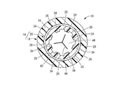
- FIG. 1 is an enlarged view showing a cross section of III-III in FIG.
- FIG. 1 is an enlarged view showing an IV-IV cross section of FIG.
- FIG. 3 is a vertical cross-sectional view of the needle assembly shown in FIG. 1, showing a state in which the valve body is opened by a pusher.
- FIGS. 1 to 4 show an indwelling needle 10 as a first embodiment of a needle assembly having a structure according to the present invention.
- the indwelling needle 10 has a structure in which the valve housing 14 is connected to the base end side of the cannula 12 as a needle body.
- the tip end side refers to the left side in FIG. 2 which is the needle tip side of the cannula 12
- the proximal end side refers to the right side in FIG. 2 which is the side opposite to the needle tip of the cannula 12.
- the axial direction means, in principle, the left-right direction in FIG. 2, which is the needle axis direction of the cannula 12.
- the cannula 12 has a hollow cylindrical shape and is formed of, for example, a soft synthetic resin.
- the cannula 12 may have a tapered shape in which the outer peripheral surface of the tip portion (not shown) gradually decreases in diameter toward the tip side. Further, a plurality of through holes may be formed in the peripheral wall of the tip portion of the cannula 12 to facilitate the inflow of a liquid such as blood into the cannula 12.
- the cannula 12 may be rigid and may be formed of, for example, metal.
- the valve housing 14 has a cylindrical shape as a whole and has a lumen 16 penetrating in the axial direction.
- the valve housing 14 is harder than the valve body 44 described later, and is formed of, for example, a hard synthetic resin.
- the valve housing 14 includes a first component 18 connected to the cannula 12 and a second component 20 connected to the first component 18.
- the first constituent member 18 has a tip portion 22 having a tapered cylindrical shape having a small diameter toward the tip as a whole.
- a cannula 12 is inserted into the tip portion 22 of the first component 18 from the tip end side, and the cannula 12 is fixed to the inner peripheral surface of the tip portion 22.
- the valve housing 14 of the present embodiment is a needle fixing portion, and the cannula 12 is directly connected to the first component 18 constituting the tip portion.
- the first constituent member 18 has a substantially cylindrical connecting cylinder portion 24 protruding from the tip portion 22 toward the base end side.
- the connecting cylinder portion 24 is thinner and has a larger inner diameter than the base end of the tip portion 22, and the inner peripheral portion of the base end surface of the tip portion 22 is an annular portion located on the inner circumference of the tip end of the connecting cylinder portion 24. It is said to be a support surface 25.
- the support surface 25 is provided at the base end portion of the tip portion 22 of the first constituent member 18, and extends inward in the radial direction.
- a concave groove 26 is formed on the inner peripheral surface and the support surface 25 of the connecting cylinder portion 24 of the first component member 18.
- the concave groove 26 is partially provided in the circumferential direction of the first constituent member 18.
- the concave groove 26 extends linearly in the radial direction on the support surface 25, and also extends linearly in the axial direction on the inner peripheral surface of the connecting cylinder portion 24.
- One end of the groove 26 reaches the inner peripheral end of the support surface 25, and the other end reaches the base end of the connecting cylinder 24.
- the number of the concave grooves 26 is not particularly limited, but is preferably a plurality, and in the present embodiment, the eight concave grooves 26 are arranged at substantially equal intervals in the circumferential direction.
- the second component 20 has a substantially cylindrical shape as a whole, and a male screw portion 28 protruding to the outer circumference is provided at the base end portion.
- the base end portion of the inner peripheral surface of the second component 20 is set with a female luer taper having a smaller diameter toward the tip end side, and is in close contact with the outer peripheral surface of the male connector 52, which will be described later.
- the second component 20 is provided with a positioning portion 30 projecting to the outer periphery at an intermediate portion in the axial direction.
- the protruding height of the positioning portion 30 gradually increases toward the tip end.
- the positioning portion 30 is provided over the entire circumference, and as shown in FIG. 3, communication grooves 32 are provided at a plurality of locations in the circumferential direction.
- the first holding portion 34 and the second holding portion 36 as holding portions project from the inner peripheral surface of the second constituent member 20.
- the first holding portion 34 is partially provided in the circumferential direction of the second component member 20 and extends linearly in the axial direction.
- a plurality of the first holding portions 34 are provided so as to be separated from each other in the circumferential direction of the second constituent member 20, and in the present embodiment, eight first holding portions 34 are provided in the circumferential direction of the second constituent member 20 and the like. Arranged at intervals.
- the first holding portion 34 is an inclined surface 38 whose protruding end surface is inclined inward toward the tip side in the axial direction, and is directed toward the tip side in the axial direction, which is the arrangement side of the valve body 44, which will be described later.
- the protruding height is large.
- the inclined surface 38 is inclined at a substantially constant inclination angle, but the inclination angle may be changed gradually or stepwise.
- the axial length of the first holding portion 34 is longer than the axial length of the valve body 44, which will be described later.
- the second holding portion 36 is partially provided in the circumferential direction of the second component member 20 and extends linearly in the axial direction.
- a plurality of the second holding portions 36 are provided so as to be separated from each other in the circumferential direction of the second constituent member 20, and in the present embodiment, eight second holding portions 36 are provided in the circumferential direction of the second constituent member 20 and the like. Arranged at intervals.
- the second holding portion 36 is arranged apart from the first holding portion 34 toward the tip end side, and a valve body accommodating portion 40 is provided between the first holding portion 34 and the second holding portion 36 in the axial direction. Has been done.
- Both the protruding end face of the first holding portion 34 and the protruding end face of the second holding portion 36 are located so as to protrude inward from the inner surface of the peripheral wall of the valve body accommodating portion 40.
- the protrusion height of the second holding portion 36 is substantially constant in the axial direction.
- the axial length of the first holding portion 34 is longer than the axial length of the second holding portion 36.
- the protruding height of the first holding portion 34 and the protruding height of the second holding portion 36 may be different from each other, but are substantially the same in the present embodiment.
- the second holding portion 36 is arranged at a position separated from the first holding portion 34 in the circumferential direction of the second constituent member 20, and in the present embodiment, the first holding portion 34 and the second holding portion 36 are arranged in the circumferential direction. Are arranged alternately.
- the inner peripheral surface of the second component 20 including the first holding portion 34 and the second holding portion 36 is divided in the axial direction. It can be molded by a simple mold structure. That is, the end face of the first holding portion 34 on the valve body accommodating portion 40 side, the both end faces and the protruding end faces of the second holding portion 36 are molded by the mold on the tip side, and the first holding is performed by the mold on the base end side. Both side end faces and protruding end faces of the portion 34 and the end faces of the second holding portion 36 on the valve body accommodating portion 40 side can be formed.
- a recess 42 is open on the outer peripheral surface of the second component 20.
- the recess 42 is provided at the tip of the second constituent member 20 that is fitted into the connecting cylinder portion 24 of the first constituent member 18.
- the recess 42 is arranged in the middle of the tip portion of the second constituent member 20 off the tip in the axial direction, and is preferably located in the center of the tip portion of the second component 20 in the axial direction.
- the recess 42 of the present embodiment is an annular shape that extends continuously in the circumferential direction.
- the cross-sectional shape of the recess 42 is not particularly limited, but in the present embodiment, it is substantially semicircular.
- the recess 42 is arranged on the base end side in the axial direction with respect to the valve body accommodating portion 40. It is desirable that the radial depth dimension of the recess 42 is larger than the depth dimension of the recess 26 of the first component member 18.
- a valve body 44 is housed in the inner circumference of the second component 20.
- the valve body 44 is an elastic body formed of rubber or the like, has a substantially disk shape, and has a notch 46 penetrating in the axial direction.
- the shape of the notch 46 is not limited, but is, for example, radial, and in the present embodiment, it is radial extending from the center to the outer circumference in three directions. It is desirable that the outer diameter dimension of the valve body 44 is larger than the inner diameter dimension of the second component 20 in the valve body accommodating portion 40.
- the valve body 44 is inserted into the second component 20 from the base end.
- the base end opening of the second component 20 has a larger diameter than the valve body 44, and the valve body 44 can be easily inserted into the base end opening of the second component 20.
- the valve body 44 moves on the inner circumference of the second component 20 toward the tip end side, gets over the first holding portion 34 toward the tip end side, and is inserted into the valve body accommodating portion 40.
- the valve body 44 gets over the first holding portion 34, it comes into contact with the inclined surface 38 which is the protruding end surface of the first holding portion 34, and gets over the first holding portion 34 while being gradually compressed by the inclined surface 38.
- the valve body 44 smoothly gets over the first holding portion 34 without being caught by the first holding portion 34, and is guided to the valve body accommodating portion 40.
- the first holding portion 34 is longer than the valve body 44 in the axial direction, the first holding portion 34 is not locally pressed against the outer peripheral surface of the valve body 44 and bites into the outer peripheral surface of the valve body 44. The surface is pressed against the inclined surface 38 of the first holding portion 34 in a wide range. Further, since the first holding portion 34 is made longer than the second holding portion 36, the inclination angle of the inclined surface 38 of the first holding portion 34 is reduced, and the valve body accommodating portion 40 of the valve body 44 is accommodated. The insertion work of is facilitated. Further, since the second holding portion 36 is shortened, the length of the second constituent member 20 can be shortened, and the valve housing 14 can be made compact in the axial direction.
- the first holding portion 34 and the second holding portion 36 are located on both sides in the axial direction with respect to the valve body 44 inserted into the valve body accommodating portion 40. Then, the movement of the valve body 44 toward the proximal end side is restricted by locking with the first holding portion 34, and the movement toward the distal end side is restricted by locking with the second holding portion 36. 2 Positioned with respect to the component 20.
- the first holding portion 34 and the second holding portion 36 for positioning the valve body 44 are both provided on the second constituent member 20, and the valve body 44 is the first holding portion 34.
- the valve body 44 is held in the positioned state by the second component 20 by overcoming the above. According to the structure of the first holding portion 34 and the second holding portion 36, the valve body 44 can be easily positioned and held by one member without sandwiching the valve body 44 between the two members. ..
- valve body 44 Since the valve body 44 that has reached the valve body accommodating portion 40 is released from contact with the first holding portion 34, the compression deformation due to the contact with the first holding portion 34 is released. Since the inner diameter of the valve body accommodating portion 40 is smaller than the outer diameter dimension of the valve body 44, the valve body 44 is arranged in the valve body accommodating portion 40 in a state of being compressed in the radial direction. As a result, the inner surfaces of the notches 46 are in close contact with each other, the notches 46 are liquid-tightly sealed, and the lumen of the second component 20 is blocked by the valve body 44.
- the second component 20 to which the valve body 44 is attached is connected to the first component 18 by fitting the tip end portion into the connecting cylinder portion 24 of the first component 18.
- the valve housing 14 is composed of the first constituent member 18 and the second constituent member 20.
- a cannula 12 projecting from the valve housing 14 to the tip end side is provided, and the valve body 44 is housed in the cavity 16 of the valve housing 14, and the indwelling needle 10 of the present embodiment is configured. ..
- the tip surface of the second constituent member 20 is in contact with the support surface 25 of the first constituent member 18. Further, the tip surface of the positioning portion 30 is overlapped with the base end surface of the first constituent member 18 in the connected state of the first constituent member 18 and the second constituent member 20. Therefore, it can be visually confirmed from the outside that the second constituent member 20 has been properly inserted into the first constituent member 18. Further, the positioning portion 30 is provided in the vicinity of the air bleeding passage 48, which will be described later, and is a cover portion that prevents a finger from blocking the air bleeding passage 48 when the user grips the outer surface of the valve housing 14. It also has a function as.
- the communication groove 32 provided in the positioning portion 30 extends in the axial direction, and prevents a finger from blocking the air bleeding passage 48 when the user grips the outer surface of the valve housing 14. Therefore, it is not necessary to separately provide a cover for preventing the communication groove 32 from being covered with a finger, and the valve housing 14 can be prevented from becoming large in size.
- a cover that covers the communication groove 32 may be separately provided.
- An air bleeding passage 48 penetrating the valve housing 14 is formed between the overlapping surfaces of the first component 18 and the second component 20 in the valve housing 14. That is, a tunnel-shaped passage is formed by covering the opening of the concave groove 26 provided in the first constituent member 18 with the second constituent member 20. One end of this tunnel-shaped passage opens to the inner peripheral surface of the valve housing 14 on the distal end side of the valve body 44 and communicates with the lumen 16 of the valve housing 14, and the other end. The portion is opened to the outer peripheral surface of the valve housing 14 through the communication groove 32 of the second component 20 and is opened to the external space A.
- the recessed groove 26 constitutes an air bleeding passage 48 that allows air to flow between the region of the valve housing 14 on the distal end side of the valve body 44 and the external space A. ..
- the air bleeding passages 48 are provided at a plurality of locations in the circumferential direction in the valve housing 14.
- the air bleeding passage 48 is provided between the overlapping surfaces of the first constituent member 18 and the second constituent member 20, for example, by means of through holes formed in the first constituent member 18 and the second constituent member 20. It is easier to secure the passage length as compared with the case where it is configured, and blood leakage is prevented more effectively. It is desirable that the air bleeding passage 48 restricts the ingress of blood while allowing the passage of air. For example, the amount of blood invading by reducing the cross-sectional area of the passage by flattening the cross-sectional shape of the passage. Can be reduced.
- the air bleeding passage 48 having a bottom arc-shaped cross section has a depth of 0.04 mm or more. less than greater 0.06 mm, and a passage sectional area it was confirmed to be greatly 0.0158Mm 2 lesser extent than 0.0087mm 2. In this range, air can be effectively discharged through the air bleeding passage 48 while preventing the liquid from leaking through the air bleeding passage 48. Further, even if the internal pressure of the first component 18 increases and a small amount of liquid flows into the air bleeding passage 48, the liquid reservoir 50, which will be described later, retains the liquid inside and bleeds air from the base end of the liquid reservoir 50. Prevents the liquid from flowing out into the passage 48. More preferably, it was confirmed that the air bleeding passage 48 having a bottom arc-shaped cross section had a depth of 0.05 mm and a passage cross-sectional area of 0.0122 mm 2.
- the recess 42 that opens on the outer peripheral surface of the second constituent member 20 is covered with the connecting cylinder portion 24 of the first constituent member 18.
- the annular liquid reservoir 50 that is continuous in the circumferential direction is formed by the recess 42. Since the liquid reservoir 50 is formed over the entire circumference between the overlapping surfaces of the connecting cylinder portion 24 of the first component 18 and the second component 20, the air bleeding passages 48 are formed at a plurality of locations in the circumferential direction. It is communicated. In other words, the liquid reservoir 50 is partially provided in the middle of the air bleeding passage 48 in the passage length direction.
- the liquid reservoir 50 is larger than the air bleeding passage 48. It is formed by area. Since the liquid reservoir 50 communicates with the air bleeding passage 48, if the liquid basin 50 is regarded as a part of the air bleeding passage 48, the air bleeding passage 48 partially expands and disconnects in the liquid reservoir 50. The area has been increased. In short, the liquid reservoir 50 is formed in the air bleeding passage 48 by forming a portion having a large cross-sectional area with respect to the surroundings in a part on the flow path extending in the axial direction.
- the liquid reservoir 50 is deeper in the overlapping direction of the first constituent member 18 and the second constituent member 20 than the air bleeding passage 48 that is out of the liquid reservoir 50.
- the liquid reservoir 50 of the present embodiment is provided between the overlapping surfaces of the inner peripheral surface of the first constituent member 18 and the outer peripheral surface of the second constituent member 20, and is linear in the axial direction in the air bleeding passage 48. It is arranged in the middle of the part that extends to.
- the liquid reservoir 50 is arranged substantially in the center of the portion extending linearly in the axial direction in the air bleeding passage 48.
- the axial length of the liquid reservoir 50 is shorter than the axial length of the portion other than the liquid reservoir 50 in the air bleeding passage 48 extending in the axial direction.
- the liquid reservoir 50 may be formed with a certain length.
- the liquid reservoir 50 is formed so as to extend in the axial direction longer than the axial length of the portion other than the liquid reservoir 50 in the air bleeding passage 48 extending in the axial direction. obtain.
- the indwelling needle 10 having such a structure is punctured into a blood vessel, for example, to form a circuit for infusion or blood collection. That is, first, an inner needle (not shown) inserted into the cannula 12 from the proximal end side through the notch 46 of the valve body 44 is punctured into the blood vessel together with the cannula 12 as the outer needle. Next, the inner needle is pulled out, and the indwelling needle 10 including the cannula 12 is indwelled in a state of being punctured into a blood vessel.
- Blood that fills the tip side of the lumen 16 with respect to the valve body 44 does not flow vigorously into the air bleeding passage 48 because the cross-sectional area of the air bleeding passage 48 is small. Infiltrate one by one.
- the blood that has entered the air bleeding passage 48 is released from the progress due to the capillary phenomenon in the liquid reservoir 50 provided in the middle of the air bleeding passage 48, and proceeds toward the proximal end side of the liquid reservoir 50. Is prevented.
- the liquid reservoir 50 By providing the liquid reservoir 50 in this way, even if a filter is not provided in the air bleeding passage 48, blood is prevented from reaching the base end opening of the air bleeding passage 48, and the valve housing 14 is increased in size.
- the indwelling needle 10 is suitable for infusion, blood collection, pediatric use, etc., where miniaturization of the valve housing 14 is particularly required. It is also possible to provide the air bleeding passage 48 with a filter that allows the passage of air and restricts the passage of blood.
- the liquid reservoir 50 since the liquid reservoir 50 has a continuous annular shape over the entire circumference, the volume of the liquid reservoir 50 is increased. Therefore, even if blood gradually enters the liquid reservoir 50, leakage of blood to the outside is prevented for a practically sufficient time for the indwelling needle 10. That is, from the time when the inner needle is pulled out from the cannula 12 and blood is introduced into the lumen 16 of the valve housing 14 until the male connector 52 described later is connected and the air bleeding passage 48 is blocked by the valve body 44. Meanwhile, blood is prevented from leaking through the air bleeding passage 48.
- the liquid reservoir 50 is annular, the air bleeding passage 48 and the liquid reservoir 50 can be communicated with each other without positioning the liquid reservoir 50 with respect to the air bleeding passage 48 partially provided in the circumferential direction. Can be done.
- the liquid reservoir 50 does not have to be annular, and may have, for example, a spot-like shape partially provided only in a portion corresponding to each air bleeding passage 48 in the circumferential direction of the valve housing 14. ..
- the male connector 52 has a substantially cylindrical shape, and a tapered male luer taper is set on the outer peripheral surface. By inserting the male connector 52 into the lumen 16 of the valve housing 14 from the proximal end side, the male connector 52 comes into close contact with the inner peripheral surface of the valve housing 14 in which the female luer taper is set.
- the male connector 52 is, for example, a male connector for a syringe, an infusion circuit, or the like.
- the male connector 52 may include a lock portion (not shown) that is screwed into the male screw portion 28 of the valve housing 14.
- the pusher 54 has a cylindrical shape that can be inserted into the lumen 16 of the valve housing 14, and the outer peripheral surface of the tip portion has a tapered tapered surface.
- the pusher 54 may be positioned radially in the lumen 16 of the valve housing 14, for example, by a ring member 56 attached to the inner peripheral surface of the valve housing 14 (see FIG. 5).
- the pusher 54 is made slidable in the axial direction with respect to the ring member 56, and the pusher 54 is guided in the axial direction by the ring member 56.
- the pusher 54 is pressed against the valve body 44 from the base end side, the notch 46 of the valve body 44 is pushed open by the pusher 54 and opened.
- the pusher 54 is pushed toward the tip end side by a male connector 52 inserted into the lumen 16 of the valve housing 14 from the base end side of the pusher 54, and deforms the valve body 44 toward the tip end side.
- the valve body 44 When the notch 46 is pushed open by the pusher 54, the valve body 44 is elastically deformed so as to be rolled toward the tip side, and is pressed against the inner peripheral surface of the valve housing 14. Then, the opening on the inner cavity 16 side of the air bleeding passage 48 located on the tip side of the valve body 44 is sealed by the valve body 44, and the air bleeding passage 48 is opened in a state where the valve body 44 is opened. It is blocked. As a result, in a state where the valve body 44 is opened and the external flow path including the lumen of the male connector 52 is connected to the lumen 16 of the valve housing 14, blood flowing through the lumen 16 passes through the air bleeding passage 48 to the external space. It does not leak to A. Further, it is also prevented that the air in the external space A is mixed into the inner cavity 16 through the air bleeding passage 48.
- the pusher 54 is not essential.
- the male connector 52 may be pressed directly against the base end surface of the valve body 44 so that the notch 46 of the valve body 44 is pushed open by the male connector 52.
- the indwelling needle 10 can be attached with the cap member 57.
- the indwelling needle 10 is attached with the cap member 57, for example, when the cannula 12 is punctured into a blood vessel and the male connector 52 such as an infusion circuit or a syringe is indwelled without being connected to the lumen 16. By doing so, it is possible to prevent blood leakage.
- the cap member 57 is, for example, a hard member made of synthetic resin.
- the cap member 57 has a structure in which a cylindrical lock cylinder portion 58 and a cylindrical or truncated cone-shaped cap main body 59 are connected to each other at a base end.
- the lock cylinder portion 58 has a thread protruding from the inner peripheral surface, and can be screwed with the male screw portion 28 of the valve housing 14.
- the cap body 59 has a tapered shape with a small diameter from the base end to the tip end.
- the base end portion of the cap body 59 has a tapered outer peripheral surface corresponding to the inner peripheral surface of the valve housing 14, and can be fitted to the valve housing 14.
- the tip portion of the cap body 59 has a larger inclination angle with respect to the axial direction than the inner peripheral surface of the valve housing 14, and is separated from the inner peripheral surface of the valve housing 14 to the inner circumference.
- the tip portion of the cap body 59 is provided with a step in the middle in the axial direction, and the tip side of the step has a smaller diameter than the base end side.
- the cap member 57 is attached to the indwelling needle 10. That is, the cap member 57 is arranged on substantially the same central axis as the second component 20 of the valve housing 14, the cap body 59 is inserted into the second component 20 from the base end side, and the lock cylinder The portion 58 is screwed into the male screw portion 28 provided at the base end of the second component 20.
- the cap body 59 moves to the tip side, and the tip portion of the cap body 59 is inserted into the notch 46 of the valve body 44.
- the notch 46 is closed by the cap body 59, and the cavity 16 of the valve housing 14 is closed by the cap body 59, so that blood leakage through the cavity 16 of the valve housing 14 is prevented.
- the opening on the inner cavity 16 side of the air bleeding passage 48 is closed by the valve body 44 deformed by being pushed by the cap body 59, and the leakage of blood through the air bleeding passage 48 is also prevented.
- the tip portion of the cap body 59 is tapered at a large rate of change as compared with the base end portion, and the tip has a sufficiently small diameter, so that the cap body 59 can be easily inserted into the notch 46.
- the indwelling needle 10 when the indwelling needle 10 is to be indwelled without being connected to an external flow path such as an infusion line or a syringe with the cannula 12 punctured into a blood vessel, the indwelling needle 10 attaches the cap member 57 to the valve housing 14. This can prevent blood leakage.
- an external flow path such as an infusion line or a syringe with the cannula 12 punctured into a blood vessel
- the lock cylinder portion 58 and the cap main body 59 are integrally formed, but the lock cylinder portion 58 and the cap main body 59 may be separately formed and fixed to be connected. .. Further, the lock cylinder portion 58 is not essential in the cap member. When the lock cylinder portion 58 is not provided, for example, the cap body 59 can be attached to the valve housing 14 by pushing it axially with respect to the lumen 16.
- the male connector 52 is removed from the indwelling needle 10 and the cap member 57 is attached to the indwelling needle 10 to form the lumen 16 and the indwelling needle 10. It is also possible to indwell the indwelling needle 10 in which the air bleeding passage 48 is blocked while the indwelling needle 10 is punctured into the blood vessel. Then, by removing the cap member 57 from the indwelling needle 10 and connecting another male connector 52 to the indwelling needle 10, infusion or medication can be performed again.
- the cap member 57 can be removed from the valve housing 14 by pulling out the cap body 59 from the valve housing 14 after unscrewing the male screw portion 28 and the lock cylinder portion 58. In this way, the cap member 57 is detachably attached to the valve housing 14.
- FIG. 7 shows an indwelling needle 60 as a second embodiment of a needle assembly having a structure according to the present invention.
- the members and parts substantially the same as those in the first embodiment are designated by the same reference numerals in the drawings, and the description thereof will be omitted.
- the indwelling needle 60 has a structure in which the valve body 44 is sandwiched between the first component 18 and the second component 64 that form the valve housing 62.
- the second constituent member 64 has a structure such that the tip portion including the second holding portion 36 and the first holding portion 34 are removed from the second constituent member 20 of the first embodiment.
- the second component 64 is a valve body accommodating portion 40 having an enlarged tip portion, and the valve body accommodating portion 40 located at the axial end of the second component 64 is directed toward the needle tip side. Is open.
- the pusher 54 and the valve body 44 are inserted from the tip end side of the second component 64.
- An annular convex portion 65 extends from the inner peripheral surface of the second constituent member 64, and when the annular convex portion 65 comes into contact with the pusher 54, the pusher 54 comes out from the base end side of the second constituent member 64. Is prevented.
- the second constituent member 64 in which the pusher 54 is housed is inserted into the connecting cylinder portion 24 of the first constituent member 18 from the base end side and is connected to the first constituent member 18. Since the valve body 44 is housed in the valve body accommodating portion 40 of the second component member 64, when the first component member 18 and the second component member 64 are assembled, the valve body 44 is housed in one component member 18 (64).
- the outer peripheral portion of the support surface 25 of the first component 18 is overlapped with the tip surface of the second component 64, and the inner peripheral portion is overlapped with the tip surface of the valve body 44.
- the valve body 44 is axially sandwiched between the support surface 25 of the first component 18 and the first holding portion 34 of the second component 64, and is positioned with respect to the valve housing 62. ..
- the concave groove 26 of the first component 18 is covered with a valve body 44 at a portion that opens to the inner peripheral portion of the support surface 25, and the outer peripheral portion of the support surface 25 and the connecting cylinder portion 24.
- the portion that opens to the inner peripheral surface is covered with the second component 64.
- the air bleeding passage 66 includes a first portion 68 in which the concave groove 26 is covered with the valve body 44 and a second portion 70 in which the concave groove 26 is covered with the second constituent member 64. It has.
- the air bleeding passage 66 communicates with the cavity 16 of the valve housing 62 in the first portion 68 extending between the overlapping surfaces of the first component 18 and the valve body 44, and the first component 18 and the second component 18 and the second.
- the second portion 70 is opened to the external space A through the communication groove 32 of the valve housing 62.
- the liquid reservoir 50 is provided in the middle of the second portion 70 of the air bleeding passage 66, and the wall portion of the liquid reservoir 50 is formed not by the valve body 44 but by the valve housing 62.
- the first portion 68 of the air bleeding passage 66 is the first constituent member 18.
- the first portion 68 can be easily formed.
- the second portion 70 of the air bleeding passage 66 is formed so as to penetrate the valve housing 62 which is harder than the valve body 44, changes in the passage cross-sectional shape and the passage cross-sectional area are suppressed, and the air can be removed. Stable drainage is achieved and blood leakage is prevented.
- valve housing 62 is composed of the first constituent member 18 and the second constituent member 64, and the second portion 70 of the air bleeding passage 66 is provided between the overlapping surfaces of the first constituent member 18 and the second constituent member 64. Since it is extended, it is easy to form an air bleeding passage 66 having a small cross-sectional area.
- the tip surface of the valve body 44 and the support surface 25 of the first component 18 are both flat, and the first portion of the air bleeding passage 66 is between the overlapping surfaces of the surfaces having a linear cross-sectional shape. 68 is formed.
- the first portion 68 of the air bleeding passage 66 is formed by a concave groove formed in the first component 18, and therefore, the air bleeding passage 66 is provided as compared with the case where the air bleeding passage 66 is provided in the easily deformable valve body 44. Shape stability is improved.
- the valve body 44 and the first constituent member 18 are provided with an air bleeding passage 66 on the overlapping surface of the surfaces having a linear cross-sectional shape, the surface having a linear cross-sectional shape such as a portion to be fitted with unevenness is provided.
- An air bleeding passage 66 may be provided between overlapping surfaces that are not mutual to each other.
- the support surface 25 of the first component 18 is provided with claws extending in the proximal direction and the concave grooves 26 for the air bleeding passage 66 alternately provided on the circumference, and an annular groove is provided on the tip surface of the valve body 44. While forming the air bleeding passage 66 on the support surface 25 of the first constituent member 18, the claw and the annular groove may be engaged with each other to improve the fixing force between the first constituent member 18 and the valve body 44.
- valve housing 62 having a structure in which the second component 64 is fitted into the inner circumference of the first component 18 from the base end side by extending the air bleeding passage 66 so as to be open to the base end side.
- the second portion 70 of the air bleeding passage 66 is easily formed between the overlapping surfaces of the first constituent member 18 and the second constituent member 64.
- the air bleeding passage 48 is formed between the overlapping surfaces of a plurality of members, but for example, at least a part of the air bleeding passage 48 may be formed by a through hole penetrating one member.
- the second portion of the air bleeding passage 48 may be formed by a through hole penetrating the first constituent member 18 in the radial direction.
- a through hole that penetrates the second component 20 in the radial direction in the vicinity of the valve body 44 may be formed, and the through hole may be an air bleeding passage 48.
- a part of the air bleeding passage 48 may be formed by utilizing the concave groove provided on the tip surface of the valve body 44.
- an air bleeding passage may be further formed between the inner surface of the valve housing 14 and the outer surface of the valve body 44.
- the air bleeding passage 48 of the above embodiment one end is communicated with the lumen 16 on the distal end side of the valve body 44, and the other end is opened to the external space A on the outer periphery of the valve housing 14.
- the air bleeding passages may be communicated with the lumen 16 on both sides of the valve body 44. That is, in the structure of FIG. 2, a through hole forming the other end of the air bleeding passage is provided so as to penetrate the second component 20 in the radial direction, and the through hole is inside on the base end side of the valve body 44. It may be communicated with the cavity 16 so that the air bleeding passage is opened to the external space A through the proximal opening of the lumen 16.
- the axial length of the air bleeding passage 48 is longer than the inner diameter of the valve housing 14 on the distal end side of the valve body 44, longer than the diameter of the valve body 44, longer than the diameter of the pusher 54, or based on the valve body 44. It is preferable that the valve housing 14 on the end side extends longer than the inner diameter.
- the air bleeding passage 48 preferably extends toward the side where the operating member such as the male connector is inserted, whereby the air bleeding passage 48 can be secured for a long time.
- the liquid reservoir 50 is preferably provided in the intermediate portion on the air bleeding passage 48, and is preferably provided in the portion of the valve housing 14 where the pusher 54 is located inward in the radial direction.
- the liquid reservoir 50 is not limited to an annular shape, and may be, for example, partially provided in a spot shape in the circumferential direction of the valve housing 14 and positioned in the circumferential direction with the air bleeding passage 48. Further, for example, a plurality of liquid reservoirs 50 may be provided in the passage length direction of the air bleeding passage 48, and by providing a plurality of liquid reservoirs 50 on one air bleeding passage 48, blood leaks. Can be prevented more effectively. The structure, shape, volume, and the like of the plurality of liquid reservoirs 50 may be different from each other.
- the liquid reservoir 50 is preferably formed on the air bleeding passage 48 extending linearly in the axial direction, and has a smaller length dimension and a larger width dimension and depth dimension than the air bleeding passage 48. Is preferable.
- the maximum cross-sectional area of the liquid reservoir 50 is preferably twice or more the cross-sectional area of the air bleeding passage 48. It is preferable that the air bleeding passage 48 is provided on the proximal end side because liquid such as blood is less likely to leak to the outside. In particular, when the liquid is provided in the intermediate portion on the air bleeding passage 48 extending in the axial direction, it is difficult for the liquid to reach the liquid reservoir 50, and when an amount of liquid exceeding the volume of the liquid reservoir 50 flows in, It is possible to realize a configuration that does not leak to the outside immediately.
- the concave groove 26 constituting the air bleeding passage 48 may be formed on the front end surface and the outer peripheral surface of the second component 20.
- the recess 42 constituting the liquid reservoir 50 may be formed on the inner peripheral surface of the first constituent member 18. It is also possible to form the liquid reservoir 50 by providing recesses on both the inner surface of the first constituent member 18 and the outer surface of the second constituent member 20.
- the position of the liquid reservoir 50 is not particularly limited, and may be formed on the tip surface of the second component 20, for example. However, since the volume of the liquid reservoir 50 is preferably large, the liquid reservoir 50 is large. It is preferably formed between the inner peripheral surface of the first constituent member 18 and the outer peripheral surface of the second constituent member 20 so that the volume can be easily secured.
- the valve body 44 may be attached to the first component 18 constituting the needle tip side of the valve housing 14.
- the first holding portion 34 and the second holding portion 36 may be provided on the inner peripheral surface of the first constituent member 18.
- the valve body accommodating portion 40 is provided in the second constituent member 20 in the embodiment, the valve body accommodating portion 40 may be provided in the first constituent member 18 instead of the second constituent member 20. , May be formed by both the first constituent member 18 and the second constituent member 20.
- the valve housing 14 may be provided with an annular groove on the tip surface of the valve body 44 and a convex portion to be inserted into the annular groove.
- An annular groove may be provided on the base end surface of the valve body 44 and a convex portion to be inserted into the annular groove may be provided on the valve housing 14, or an annular groove may be provided on the tip surface and the base end surface of the valve body 44 to insert the convex portion. It may be included.
- the valve housing 14 may be configured by combining three or more members, or may be configured by one member.
- the valve housing 14 may be made of a transparent material or an opaque material.
- the positioning portion 30 is also a cover portion that prevents the user's finger from blocking the air bleeding passage 48, but the cover portion may be provided separately from the positioning portion 30.
- the valve housing 14 is connected to the needle fixing portion connected to the needle body by, for example, FIG. 14 of International Publication No. 2019/027024, and a flexible tube to the needle fixing portion. It may be a structure including a valve housing. That is, the first component member and the second component member may form a valve housing, the tube may be connected to the tip end portion of the first component member, and the tip end portion of the tube may be connected to the needle fixing portion. As described above, the first component is not limited to the one directly connected to the needle body. In FIG. 14 and the like of International Publication No.
- the tube connecting the needle fixing portion and the valve housing extends from the needle fixing portion toward the proximal end side, but for example, the lumen of the needle fixing portion is branched.
- the tube connected to the valve housing may extend to the side of the needle fixing portion when the needle is opened laterally. Further, a sharp metal needle may be fixed to the tip of the valve housing 14 to form a structure that does not require an inner needle.
- the method of fixing the first constituent member 18 and the second constituent member 20 is not limited to the fitting shown in the above embodiment, and may be ultrasonic welding, adhesion, locking, screwing, or the like.
- a convex portion is provided on the outer surface of the second constituent member 20
- a through hole is provided in the first constituent member 18, and the convex portion engages with the through hole, whereby the first constituent member 18 and the second constituent member 20 are provided. May be fixed. Further, when the first constituent member 18 and the second constituent member 20 are fitted, the first constituent member 18 may be fitted into the second constituent member 20.
- the first constituent member 18 is formed with a concave groove 26 forming an air bleeding passage 48
- the second constituent member 20 is formed with a recess 42 forming a liquid reservoir 50 to bleed air.
- the first constituent member 18 and the second constituent member 20 are fixed so that the passage 48 and the liquid reservoir portion 50 communicate with each other.
- the first component is formed.
- the air bleeding passage 48 provided with the liquid reservoir 50 may be formed regardless of the axial positions of the first constituent member 18 and the second constituent member 20.
- the first holding portion 34 may be provided on the needle tip side of the valve body 44, and the second holding portion 36 may be provided on the proximal end side of the valve body 44.
- a safety mechanism for preventing erroneous puncture can be arranged in the lumen 16 of the valve housing 14.
- the safety mechanism covers and protects the needle tip of the inner needle when the inner needle is pulled out from the valve housing 14, for example, Japanese Patent Application Laid-Open No. 2002-85558, Japanese Patent No. 4510619, US Pat. No. 4,929241.
- Various known structures exemplified in the specification and the like can be adopted.
- the safety mechanism When placed inside the pusher, the safety mechanism is located between the pusher and the inner needle and is held so that it does not unintentionally detach from the valve housing by engaging with the inner surface of the pusher. May be good.
- annular protrusion or recess is provided on the inner surface of the pusher, and a part of the safety mechanism engages with the annular protrusion or recess so that the safety mechanism does not unintentionally detach from the valve housing.
- the annular protrusion or recess and a part of the safety mechanism may be in a disengaged state so that the safety mechanism can be detached from the valve housing.
- the safety mechanism may be held in the valve housing by engaging with the lumen 16 of the valve housing 14 on the proximal end side of the pusher 54, or may be assembled to the outside of the valve housing 14. It may be held in the valve housing and various known safety mechanisms can be provided.
- Indwelling needle (needle assembly first embodiment) 12 cannula (needle body) 14 Valve housing 16 Inner cavity 18 First component 20 Second component 22 Tip part 24 Connecting cylinder part 25 Support surface 26 Concave groove 28 Male thread part 30 Positioning part 32 Communication groove 34 First holding part (holding part) 36 Second holding part 38 Inclined surface 40 Valve body accommodating part 42 Recess 44 Valve body 46 Notch 48 Air bleeding passage 50 Liquid reservoir 52 Male connector 54 Pusher 56 Ring member 57 Cap member 58 Lock cylinder 59 Cap body 60 Detention Needle (needle assembly second embodiment) 62 Valve housing 64 Second component 65 Annular convex portion 66 Air bleeding passage 68 First part 70 Second part A External space
Abstract
弁体よりも針先側の空気を排出しつつ、血液の漏出を防ぐことができる、新規な構造の針組立体を提供すること。 中空の針体12と、針体12の基端側に設けられる筒状の弁ハウジング14と、弁ハウジング14の内腔16に収容されて弁ハウジング14の内腔16の連通と遮断を切り替える弁体44とを備える針組立体10であって、弁ハウジング14を貫通するエア抜き通路48が設けられて、エア抜き通路48が弁体44よりも針体12の針先側において弁ハウジング14の内腔16に連通されており、エア抜き通路48の途中には部分的に断面積が大きくされた液溜部50が設けられている。
Description
本発明は、例えば弁体付き留置針などの針組立体に関するものである。
従来から、静脈用留置針などの針組立体において、血液の逆流を防ぐための弁体を備えるものがある。針組立体は、例えば、針体の基端側に接続された弁ハウジングの内腔に弁体が収容された構造を有している。これにより、例えば静脈に穿刺された針組立体において、弁ハウジングの内腔へ入った血液が外部への流出を弁体によって阻止される。このような弁体を備えた針組立体としては、例えば特開2002-263197号公報(特許文献1)などがある。
ところで、弁ハウジングの内腔を遮断する弁体を設ける場合には、針体が血管等に穿刺された状態において、弁ハウジングの内腔における弁体よりも針先側の領域を血液によって満たすために空気を排出する必要がある。そこで、特許文献1では、弁体の外周面に軸方向に貫通するエア抜溝が形成されており、このエア抜溝によって弁体と弁ハウジングの間に構成されるエア抜き通路を通じて、弁体よりも針先側の空気が基端側へ排出されるようになっている。
しかしながら、弁体と弁ハウジングの間にエア抜き通路を形成すると、エア抜き通路が十分に確保されないおそれがあった。即ち、弁体は、変形によって弁ハウジングの内腔の連通と遮断を切替可能とする弾性体であることから、弁ハウジングへの組み付け後において、特に弁体の外面が歪み、エア抜き通路の断面形状や断面積が変化し得る。それゆえ、安定的に空気が抜けない可能性があった。
本発明の解決課題は、弁体よりも針先側の空気を排出しつつ、血液の漏出を防ぐことができる、新規な構造の針組立体を提供することにある。
以下、本発明を把握するための好ましい態様について記載するが、以下に記載の各態様は、例示的に記載したものであって、適宜に互いに組み合わせて採用され得るだけでなく、各態様に記載の複数の構成要素についても、可能な限り独立して認識及び採用することができ、適宜に別の態様に記載の何れかの構成要素と組み合わせて採用することもできる。それによって、本発明では、以下に記載の態様に限定されることなく、種々の別態様が実現され得る。
第1の態様は、中空の針体と、該針体の基端側に設けられる筒状の弁ハウジングと、該弁ハウジングの内腔に収容されて該弁ハウジングの該内腔の連通と遮断を切り替える弁体とを備える針組立体であって、前記弁ハウジングを貫通するエア抜き通路が設けられて、該エア抜き通路が前記弁体よりも前記針体の針先側において該弁ハウジングの前記内腔に連通されており、該エア抜き通路の途中には部分的に断面積が大きくされた液溜部が設けられているものである。
本態様に従う構造とされた針組立体によれば、エア抜き通路が弁体よりも硬質の弁ハウジングを貫通して設けられることにより、エア抜き通路の断面形状および断面積が安定する。
エア抜き通路の途中に断面積が大きくされた液溜部が設けられていることにより、毛細管現象によってエア抜き通路に入った血液の進行が液溜部において阻止される。それゆえ、弁ハウジングの内腔における弁体よりも針先側の領域に入った血液が、エア抜き通路を通じて外部へ漏出するのを防ぐことができる。
第2の態様は、第1の態様に記載された針組立体において、前記エア抜き通路が前記弁ハウジングにおける周方向の複数箇所に設けられているものである。
本態様に従う構造とされた針組立体によれば、複数のエア抜き通路を通じて空気を効率的に排出することができる。また、空気の排出に必要なエア抜き通路の総断面積を確保しつつ、各エア抜き通路の通路断面積を小さくすることができて、エア抜き通路に対する血液の浸入を抑えることができる。
第3の態様は、第1または第2の態様に記載された針組立体において、前記液溜部が前記弁ハウジングの周方向に連続する環状とされているものである。
本態様に従う構造とされた針組立体によれば、液溜部の容積を大きくすることができ、エア抜き通路を通じた血液の漏出をより効果的に防止することができる。
第4の態様は、第1~第3の何れか1つの態様に記載された針組立体において、前記弁ハウジングが第1構成部材と該第1構成部材の基端側に連結された第2構成部材とを備えており、前記エア抜き通路がそれら第1構成部材と第2構成部材の間に形成されているものである。
本態様に従う構造とされた針組立体によれば、第1構成部材と第2構成部材の間にエア抜き通路を形成することによって、1つの部材を貫通するエア抜き通路を形成する場合よりもエア抜き通路の断面形状および断面積をより大きな自由度で設計することができる。特に、エア抜き通路の断面積を小さくすることにより、エア抜き通路に浸入する血液の量を抑えることができる。
第5の態様は、第4の態様に記載された針組立体において、前記第2構成部材が前記第1構成部材の内周へ嵌め入れられて連結されており、該第2構成部材における該第1構成部材への嵌入部分の外周面に開口する凹所によって前記液溜部が構成されているものである。
本態様に従う構造とされた針組立体によれば、第2構成部材が第1構成部材の内周へ嵌め入れられることにより、第2構成部材に設けられた凹所の開口が第1構成部材によって覆われて液溜部が形成されることから、液溜部を第2構成部材と第1構成部材の間に簡単に形成することができる。
液溜部を形成するための凹所を第2構成部材の外周面に開口するように形成することにより、凹所を精度よく形成することができ、エア抜き通路を通じた血液の漏出をより効果的に防止することができる。
第6の態様は、第4又は第5の態様に記載された針組立体において、前記第1構成部材の基端部分には径方向内方へ向かって延びて前記弁体と前記第2構成部材との少なくとも一方に重ね合わされる支持面が設けられ、該支持面には前記エア抜き通路を構成する凹溝が開口しており、前記弁ハウジングに対して基端側から挿入される操作部材によって該弁体が先端側に変形することによって該弁体が該エア抜き通路を塞ぐようにしたものである。
本態様に従う構造とされた針組立体によれば、弁体に凹溝を設けてエア抜き通路を形成する場合に比して、安定してエア抜き通路を実現できる。また、弁の近傍にエア抜き通路の端部が形成されるため、弁ハウジングの基端から操作部材が挿入された場合、エア抜き通路と弁ハウジングの内腔とを確実に非連通状態とすることができ、弁ハウジング内の圧力が大きくなっても、エア抜き通路内に当該圧力が作用しにくく、エア抜き通路内の液体が外部に漏出する事態を抑止することができる。
第7の態様は、第1~第6の何れか1つの態様に記載された針組立体において、前記弁ハウジングに対して基端側から挿入されて、該弁ハウジングの前記内腔を塞ぐと共に、前記弁体を先端側へ変形させて前記エア抜き通路を該弁体で塞ぐキャップ部材を備えており、該キャップ部材が該弁ハウジングに対して着脱可能とされているものである。
本態様に従う構造とされた針組立体によれば、例えば、針体が患者の血管へ穿刺された状態で留置される場合に、キャップ部材を弁ハウジングの内腔へ挿入して取り付けることにより、弁ハウジングの内腔とエア抜き通路とをそれぞれ塞ぐことができる。これにより、弁ハウジングの内腔やエア抜き通路を通じて血液が漏れ出すのを防ぐことができて、例えば、針組立体を留置状態で比較的に長い時間にわたって保持することも可能となる。
第8の態様は、中空の針体と、該針体の基端側に設けられる筒状の弁ハウジングと、該弁ハウジングの内腔に収容されて該弁ハウジングの該内腔の連通と遮断を切り替える弁体とを備える針組立体であって、前記弁ハウジングの内周面から突出する保持部が設けられて、該保持部は、該弁ハウジングの周方向において部分的に設けられていると共に、突出高さが該弁体側に向けて大きくなっていくように傾斜する傾斜面を有するものである。
本態様に従う構造とされた針組立体によれば、保持部が傾斜面とされていることにより、弁体を弁ハウジングの内腔において基端側から針先側へ向けて移動させることにより、弁体が保持部の傾斜面によって案内されて保持部を容易に乗り越え、弁体を弁ハウジングの内腔に対して軸方向へ簡単に差し入れることができる。
保持部は、弁ハウジングの周方向において部分的に設けられていることから、弁体が保持部の傾斜面に摺接して案内される際に、弁体と保持部の接触面積が小さい。それゆえ、弁体を弁ハウジングの内腔に対して軸方向へ差し入れるために必要な力が低減されて、弁体の弁ハウジングへの取付作業が容易になる。
本発明によれば、針組立体において、弁体よりも針先側の空気を排出しつつ、血液の漏出を防ぐことができる。
以下、本発明の実施形態について、図面を参照しつつ説明する。
図1~4には、本発明に従う構造とされた針組立体の第1実施形態として、留置針10が示されている。留置針10は、針体としてのカニューラ12の基端側に弁ハウジング14が接続された構造を有している。以下の説明において、原則として、先端側とはカニューラ12の針先側である図2中の左側を、基端側とはカニューラ12の針先と反対側である図2中の右側を言う。また、軸方向とは、原則として、カニューラ12の針軸方向である図2中の左右方向を言う。
カニューラ12は、中空筒状であって、例えば軟質の合成樹脂によって形成されている。カニューラ12は、図示しない先端部分の外周面が先端側に向かって次第に小径となるテーパ状であってもよい。また、カニューラ12の先端部分の周壁に複数の貫通孔が形成されて、血液等の液体がカニューラ12内へ流入し易くされていてもよい。カニューラ12は、硬質であってもよく、例えば金属によって形成することもできる。
弁ハウジング14は、全体として筒状とされており、軸方向に貫通する内腔16を有している。弁ハウジング14は、後述する弁体44よりも硬質とされており、例えば硬質の合成樹脂によって形成されている。弁ハウジング14は、図2に示すように、カニューラ12に接続される第1構成部材18と、第1構成部材18に連結される第2構成部材20とを含んで構成されている。
第1構成部材18は、全体として先端に向けて小径となるテーパ筒状とされた先部22を有している。第1構成部材18の先部22にはカニューラ12が先端側から挿入されており、カニューラ12が先部22の内周面に固着されている。本実施形態の弁ハウジング14は、針固定部とされており、先端部分を構成する第1構成部材18にカニューラ12が直接的に接続されている。また、第1構成部材18は、先部22から基端側へ突出する略円筒形状の連結筒部24を有している。連結筒部24は、先部22の基端よりも薄肉且つ内径が大きくされており、先部22の基端面の内周部分が、連結筒部24の先端よりも内周に位置する環状の支持面25とされている。支持面25は、第1構成部材18の先部22の基端部分に設けられており、径方向内方へ向かって延びている。
第1構成部材18における連結筒部24の内周面および支持面25には、凹溝26が形成されている。凹溝26は、第1構成部材18の周方向において部分的に設けられている。凹溝26は、支持面25において径方向に直線的に延びていると共に、連結筒部24の内周面において軸方向に直線的に延びている。凹溝26は、一方の端部が支持面25の内周端に達していると共に、他方の端部が連結筒部24の基端に達している。凹溝26の数は特に限定されないが、好適には複数とされ、本実施形態では8つの凹溝26が周方向において略等間隔に配されている。
第2構成部材20は、全体として略円筒形状とされており、基端部には外周へ突出する雄ねじ部28が設けられている。第2構成部材20の内周面における基端部分は、先端側へ向けて小径となるメスルアーテーパが設定されており、後述するオスコネクタ52の外周面に密着するようになっている。
第2構成部材20は、軸方向の中間部分において外周へ突出する位置決め部30が設けられている。位置決め部30は、先端へ向けて次第に突出高さが大きくなっている。また、位置決め部30は、全周にわたって設けられていると共に、図3に示すように、周方向の複数箇所に連通溝32が設けられている。
第2構成部材20の内周面には、保持部としての第1保持部34と第2保持部36が突出している。第1保持部34は、第2構成部材20の周方向において部分的に設けられて、軸方向に直線的に延びている。第1保持部34は、第2構成部材20の周方向において複数が相互に離隔して設けられており、本実施形態では8つの第1保持部34が第2構成部材20の周方向において等間隔に配されている。第1保持部34は、突出端面が軸方向の先端側に向けて内周へ傾斜する傾斜面38とされており、後述する弁体44の配設側である軸方向の先端側へ向けて突出高さが大きくなっている。傾斜面38は、本実施形態では略一定の傾斜角度で傾斜しているが、傾斜角度が徐々に或いは段階的に変化していてもよい。第1保持部34の軸方向長さは、後述する弁体44の軸方向長さよりも長くされている。
第2保持部36は、第2構成部材20の周方向において部分的に設けられて、軸方向に直線的に延びている。第2保持部36は、第2構成部材20の周方向において複数が相互に離隔して設けられており、本実施形態では8つの第2保持部36が第2構成部材20の周方向において等間隔に配されている。第2保持部36は、第1保持部34に対して先端側へ離れて配されており、第1保持部34と第2保持部36の軸方向間には、弁体収容部40が設けられている。第1保持部34の突出端面と第2保持部36の突出端面は、何れも弁体収容部40の周壁内面よりも内周に突出して位置している。第2保持部36は、突出高さが軸方向において略一定とされている。第1保持部34の軸方向の長さは、第2保持部36の軸方向の長さよりも長くされている。第1保持部34の突出高さと第2保持部36の突出高さは、互いに異なっていてもよいが、本実施形態では略同じとされている。
第2保持部36は、第2構成部材20の周方向において第1保持部34を外れた位置に配置されており、本実施形態では、周方向において第1保持部34と第2保持部36が交互に配されている。これにより、第2構成部材20を射出成形等の型成形によって製造する際に、第1保持部34と第2保持部36を備える第2構成部材20の内周面を、軸方向に分割された簡単な金型構造によって成形することができる。即ち、先端側の金型によって第1保持部34の弁体収容部40側の端面と第2保持部36の両側端面及び突出端面とを成形すると共に、基端側の金型によって第1保持部34の両側端面及び突出端面と第2保持部36の弁体収容部40側の端面とを成形することができる。
第2構成部材20の外周面には、凹所42が開口している。凹所42は、第1構成部材18の連結筒部24に嵌入される第2構成部材20の先端部分に設けられている。凹所42は、第2構成部材20の先端部分において軸方向先端を外れた中間に配されており、好適には、第2構成部材20の先端部分において軸方向の中央に位置している。本実施形態の凹所42は、周方向に連続して延びる環状とされている。凹所42の断面形状は、特に限定されないが、本実施形態では略半円形とされている。凹所42は、弁体収容部40よりも軸方向の基端側に配置されている。凹所42の径方向の深さ寸法は、第1構成部材18の凹溝26の深さ寸法よりも大きくされていることが望ましい。
第2構成部材20の内周には、弁体44が収容されている。弁体44は、ゴムなどによって形成された弾性体とされており、略円板形状とされていると共に、軸方向に貫通する切込み46が形成されている。切込み46は、形状を限定されるものではないが、例えば放射状とされており、本実施形態では中央から外周へ向けて3方向へ延びる放射状とされている。弁体44の外径寸法は、弁体収容部40における第2構成部材20の内径寸法よりも大きくされていることが望ましい。
弁体44は、第2構成部材20に対して基端から挿入される。第2構成部材20の基端開口は弁体44よりも大径とされており、弁体44が第2構成部材20の基端開口へ簡単に挿入可能とされている。弁体44は、第2構成部材20の内周を先端側へ移動し、第1保持部34を先端側へ乗り越えて、弁体収容部40へ差し入れられる。弁体44は、第1保持部34を乗り越える際に、第1保持部34の突出端面である傾斜面38に当接し、傾斜面38によって徐々に圧縮されながら第1保持部34を乗り越える。これにより、弁体44は、第1保持部34に引っ掛かることなく、第1保持部34をスムーズに乗り越えて、弁体収容部40まで案内される。
第1保持部34が弁体44よりも軸方向において長くされていることにより、第1保持部34が弁体44の外周面に局所的に押し当てられて食い込むことなく、弁体44の外周面が広い範囲において第1保持部34の傾斜面38に押し当てられる。また、第1保持部34が第2保持部36よりも長くされていることによって、第1保持部34の傾斜面38の傾斜角度が小さくされており、弁体44の弁体収容部40への挿入作業が容易になる。また、第2保持部36が短くされていることによって、第2構成部材20の長さを短くすることができて、弁ハウジング14を軸方向においてコンパクトにできる。
第1保持部34と第2保持部36は、弁体収容部40へ差し入れられた弁体44に対して、軸方向の両側に位置している。そして、弁体44は、基端側への移動が第1保持部34との係止によって制限されると共に、先端側への移動が第2保持部36との係止によって制限されて、第2構成部材20に対して位置決めされている。本実施形態の弁ハウジング14において、弁体44を位置決めする第1保持部34と第2保持部36は、何れも第2構成部材20に設けられており、弁体44が第1保持部34を乗り越えることによって、弁体44が第2構成部材20によって位置決め状態で保持される。このような第1保持部34および第2保持部36の構造によれば、弁体44を2つの部材の間に挟むことなく、弁体44を1つの部材によって簡単に位置決め保持することができる。
弁体収容部40に達した弁体44は、第1保持部34への当接が解除されることから、第1保持部34への当接による圧縮変形が解除される。弁体収容部40の内径寸法が弁体44の外径寸法よりも小さいことから、弁体44は径方向に圧縮された状態で弁体収容部40に配設されている。これにより、切込み46の内面が相互に密着して、切込み46が液密に封止されており、第2構成部材20の内腔が弁体44によって遮断されている。
弁体44が取り付けられた第2構成部材20は、先端部分が第1構成部材18の連結筒部24に嵌め入れられることにより、第1構成部材18に連結されている。これにより、弁ハウジング14が第1構成部材18と第2構成部材20によって構成されている。第1構成部材18の内腔と第2構成部材20の内腔が接続されることにより、軸方向に貫通する弁ハウジング14の内腔16が構成されている。そして、弁ハウジング14から先端側へ突出するカニューラ12が設けられていると共に、弁ハウジング14の内腔16には弁体44が収容されており、本実施形態の留置針10が構成されている。
第1構成部材18と第2構成部材20の連結状態において、第2構成部材20の先端面は、第1構成部材18の支持面25に当接している。また、位置決め部30の先端面は、第1構成部材18と第2構成部材20の連結状態において、第1構成部材18の基端面に重ね合わされる。それゆえ、第2構成部材20が第1構成部材18に対して適切に挿入されたことを、目視等によって外部から確認することができる。また、位置決め部30は、後述するエア抜き通路48の近傍に設けられて、弁ハウジング14の外面を使用者が把持した場合に、指がエア抜き通路48を塞いでしまうことを防止するカバー部としての機能も有する。また、位置決め部30に設けられた連通溝32は、軸方向に延びており、弁ハウジング14の外面を使用者が把持した場合に、指がエア抜き通路48を塞いでしまうことを防止する。このため、連通溝32が指で覆われないようにするためのカバーを別途設ける必要が無く、弁ハウジング14の大型化が防止される。なお、連通溝32を覆うカバーを別途設けることもできる。
弁ハウジング14における第1構成部材18と第2構成部材20の重ね合わせ面間には、弁ハウジング14を貫通するエア抜き通路48が形成されている。即ち、第1構成部材18に設けられた凹溝26の開口が、第2構成部材20によって覆われることにより、トンネル状の通路が形成されている。このトンネル状の通路は、一方の端部が、弁体44よりも先端側において弁ハウジング14の内周面に開口して、弁ハウジング14の内腔16に連通されていると共に、他方の端部が、第2構成部材20の連通溝32を通じて弁ハウジング14の外周面に開口して、外部空間Aに開放されている。これにより、弁ハウジング14の内腔16における弁体44よりも先端側の領域と、外部空間Aとの間において、空気の流動を許容するエア抜き通路48が、凹溝26によって構成されている。エア抜き通路48は、弁ハウジング14において周方向の複数箇所に設けられている。エア抜き通路48は、第1構成部材18と第2構成部材20の重ね合わせ面間に設けられていることにより、例えば、第1構成部材18や第2構成部材20に形成された貫通孔によって構成される場合に比して通路長を確保し易く、血液の漏出がより効果的に防止される。エア抜き通路48は、空気の通過を許容しつつ、血液の浸入を制限することが望ましく、例えば、通路断面形状を扁平にするなどして通路断面積を小さくすることにより、浸入する血液の量を少なくすることができる。
なお、40mmHgまで空気圧をかけてエア抜き通路48を通じた液体の漏れを確認する実験を行った結果、好適には、底面円弧状の断面を有するエア抜き通路48において、深さが0.04mmより大きく0.06mmより小さく、且つ通路断面積が0.0087mm2より大きく0.0158mm2より小さい範囲とされることが確認された。当該範囲において、エア抜き通路48を通じた液体の漏れを防ぎつつ、エア抜き通路48を通じて空気を有効に排出することができる。また、第1構成部材18の内圧が高まり、エア抜き通路48内に少量の液体が流入したとしても、後述する液溜部50が液体を内部に留め、液溜部50より基端のエア抜き通路48に液体が流出することを防止する。なお、より好適には、底面円弧状の断面を有するエア抜き通路48において、深さが0.05mm、通路断面積が0.0122mm2とされることが確認された。
第2構成部材20の外周面に開口する凹所42は、第1構成部材18の連結筒部24によって覆われている。これにより、周方向に連続する環状の液溜部50が、凹所42によって構成されている。液溜部50は、第1構成部材18の連結筒部24と第2構成部材20との重ね合わせ面間において全周にわたって形成されていることから、周方向の複数箇所においてエア抜き通路48に連通されている。換言すれば、液溜部50は、エア抜き通路48の通路長方向の途中に部分的に設けられている。エア抜き通路48の通路長方向と直交する断面において、凹所42の断面積が凹溝26の断面積よりも大きくされていることから、液溜部50は、エア抜き通路48よりも大きな断面積で形成されている。液溜部50はエア抜き通路48に連通されていることから、液溜部50をエア抜き通路48の一部とみなせば、エア抜き通路48が液溜部50において部分的に拡大して断面積を大きくされている。要するに、軸方向に延びる流路上の一部に断面積が周囲に比して大きい部分が形成されることで、エア抜き通路48に液溜部50が形成されている。特に、液溜部50は、液溜部50を外れたエア抜き通路48よりも、第1構成部材18と第2構成部材20の重ね合わせ方向の深さが深くされている。本実施形態の液溜部50は、第1構成部材18の内周面と第2構成部材20の外周面との重ね合わせ面間に設けられており、エア抜き通路48において軸方向に直線的に延びる部分の途中に配されている。特に本実施形態では、液溜部50がエア抜き通路48において軸方向に直線的に延びる部分の略中央に配置されている。液溜部50の軸方向長さは、軸方向に延びるエア抜き通路48における液溜部50以外の部分の軸方向長さよりも短くされている。なお、液溜部50は、ある程度の長さをもって形成されていてもよく、例えば軸方向に延びるエア抜き通路48における液溜部50以外の部分の軸方向長さより長く軸方向に延びて形成され得る。
このような構造とされた留置針10は、例えば、血管に穿刺されて、輸液や採血などの回路を構成する。即ち、先ず、弁体44の切込み46を通じてカニューラ12に基端側から挿通された図示しない内針が、外針としてのカニューラ12とともに血管へ穿刺される。次に、内針が抜き取られて、カニューラ12を含む留置針10が血管への穿刺状態で留置される。
カニューラ12が血管に穿刺されることにより、内針を引き抜くと、カニューラ12を通じて血液が弁ハウジング14の内腔16へ入るが、弁体44の切込み46が封止されていることによって、血液は弁ハウジング14の内腔16において弁体44よりも先端側に留まる。また、内腔16の弁体44よりも先端側を満たす空気は、血液の内腔16への導入に際して、エア抜き通路48を通じて外部空間Aへ排出される。これにより、内腔16の弁体44よりも先端側は、血液によって満たされて、空気の混入が防止される。
内腔16の弁体44よりも先端側を満たす血液は、エア抜き通路48の断面積が小さいことから、エア抜き通路48に勢いよく流れ込むことはないが、毛細管現象によってエア抜き通路48に少しずつ浸入する。ここにおいて、エア抜き通路48に浸入した血液は、エア抜き通路48の途中に設けられた液溜部50において、毛細管現象による進行が解除されて、液溜部50よりも基端側への進行が防止される。このように液溜部50を設けることにより、エア抜き通路48内にフィルタが設けられていなくても、血液がエア抜き通路48の基端開口まで達するのを防いで、弁ハウジング14の大型化を防ぎつつ血液のエア抜き通路48を通じた外部空間Aへの漏出が回避される。従って、留置針10は、弁ハウジング14の小型化が特に求められる点滴等の輸液用,採血用,小児用等において好適である。なお、エア抜き通路48に対して、空気の通過を許容し、且つ血液の通過を制限するフィルタを設けることも可能である。
本実施形態では、液溜部50が全周にわたって連続する環状とされていることから、液溜部50の容積が大きくされている。それゆえ、液溜部50へ少しずつ血液が入ったとしても、血液の外部への漏出が留置針10の実用上において十分な時間にわたって防止される。すなわち、内針がカニューラ12から抜き取られて、弁ハウジング14の内腔16に血液が導入されてから、後述するオスコネクタ52が接続されてエア抜き通路48が弁体44によって遮断されるまでの間、血液がエア抜き通路48を通じて漏れ出さないようにされている。また、液溜部50が環状であれば、周方向において部分的に設けられるエア抜き通路48に対して液溜部50を位置決めすることなく、エア抜き通路48と液溜部50を連通させることができる。なお、液溜部50は、環状ではなくてもよく、例えば、弁ハウジング14の周方向において各エア抜き通路48に対応する部分だけに部分的に設けられたスポット的な形状とすることもできる。
留置針10は、図5に示すように、操作部材としてのオスコネクタ52が弁ハウジング14に対して接続されることによって、弁体44の切込み46が押し子54によって押し開かれて、弁ハウジング14の内腔16とオスコネクタ52の内腔が押し子54の内腔を通じて連通される。
オスコネクタ52は、略円筒形状であって、先細となるオスルアーテーパが外周面に設定されている。オスコネクタ52は、弁ハウジング14の内腔16へ基端側から挿入されることによって、メスルアーテーパが設定された弁ハウジング14の内周面に対して密着するようになっている。オスコネクタ52は、例えば、シリンジや輸液回路等のオスコネクタとされる。なお、オスコネクタ52は、弁ハウジング14の雄ねじ部28に螺合する図示しないロック部を備えていてもよい。
押し子54は、弁ハウジング14の内腔16へ挿入可能な筒状とされており、先端部分の外周面が先細のテーパ面とされている。押し子54は、例えば、弁ハウジング14の内周面に取り付けられるリング部材56によって、弁ハウジング14の内腔16において径方向に位置決めされるようにしてもよい(図5参照)。この場合には、押し子54がリング部材56に対して軸方向に摺動可能とされて、押し子54がリング部材56によって軸方向に案内される。そして、押し子54が弁体44に基端側から押し当てられることにより、弁体44の切込み46が押し子54によって押し開かれて開放される。押し子54は、押し子54よりも基端側から弁ハウジング14の内腔16へ挿入されるオスコネクタ52によって先端側へ押し込まれて、弁体44を先端側に変形させる。
弁体44は、押し子54によって切込み46を押し開かれることにより、先端側へ捲れるように弾性変形して、弁ハウジング14の内周面に押し当てられる。そして、弁体44よりも先端側に位置するエア抜き通路48の内腔16側の開口部が、弁体44によって封止されており、弁体44が開放された状態においてエア抜き通路48が遮断される。これにより、弁体44が開放されてオスコネクタ52の内腔を含む外部流路が弁ハウジング14の内腔16に接続された状態において、内腔16を流れる血液がエア抜き通路48を通じて外部空間Aへ漏れ出すことがない。また、外部空間Aの空気がエア抜き通路48を通じて内腔16へ混入することも防止される。
本実施形態では、弁体44の切込み46が押し子54によって開放される構造について説明したが、押し子54は必須ではない。例えば、オスコネクタ52が弁体44の基端面に直接的に押し付けられて、オスコネクタ52によって弁体44の切込み46が押し開かれるようにしてもよい。
ところで、留置針10は、図6に示すように、キャップ部材57を取り付けることが可能とされている。そして、留置針10は、例えば、カニューラ12が血管へ穿刺された状態で、輸液回路やシリンジなどのオスコネクタ52が内腔16に接続されることなく留置される場合に、キャップ部材57が取り付けられることにより、血液の漏出を防ぐことができる。
キャップ部材57は、例えば合成樹脂によって形成された硬質の部材とされている。キャップ部材57は、円筒状のロック筒部58と、円柱状乃至は円錐台状のキャップ本体59とが、基端において相互に連結された構造を有している。ロック筒部58は、内周面にねじ山が突出しており、弁ハウジング14の雄ねじ部28と螺合可能とされている。
キャップ本体59は、基端から先端へ向けて小径となる先細形状を有している。キャップ本体59の基端部分は、弁ハウジング14の内周面に対応するテーパ状の外周面を有しており、弁ハウジング14に対して嵌合可能とされている。キャップ本体59の先端部分は、弁ハウジング14の内周面よりも軸方向に対する傾斜角度が大きくなっており、弁ハウジング14の内周面に対して内周へ離れている。キャップ本体59の先端部分は、軸方向の途中に段差を備えており、段差よりも先端側が基端側よりも小径とされている。
図6に示すように、キャップ部材57は、留置針10に取り付けられる。即ち、キャップ部材57は、弁ハウジング14の第2構成部材20に対して略同一中心軸上に配置されて、キャップ本体59が第2構成部材20に基端側から挿入されると共に、ロック筒部58が第2構成部材20の基端に設けられた雄ねじ部28に螺合される。
雄ねじ部28とロック筒部58を締め込むことにより、キャップ本体59が先端側へ移動し、キャップ本体59の先端部分が弁体44の切込み46に挿通される。これにより、切込み46がキャップ本体59によって塞がれて、弁ハウジング14の内腔16がキャップ本体59によって塞がれることから、弁ハウジング14の内腔16を通じた血液の漏出が防止される。また、エア抜き通路48の内腔16側の開口が、キャップ本体59で押されて変形した弁体44によって塞がれて、エア抜き通路48を通じた血液の漏出も防止される。キャップ本体59の先端部分は、基端部分に比して大きな変化率で先細となっており、先端が十分に小径とされていることから、切込み46への挿通が容易となっている。
例えば、血管へカニューラ12を穿刺した状態で留置針10を輸液ラインやシリンジ等の外部流路に接続することなく留置したい場合などに、留置針10は、キャップ部材57を弁ハウジング14へ取り付けることによって、血液の漏出を防止することができる。
キャップ本体59の基端部分が弁ハウジング14に嵌合されることにより、弁ハウジング14の内腔16を通じた血液の漏出が、キャップ本体59と弁ハウジング14との重ね合わせによっても防止される。また、キャップ本体59の基端部分と弁ハウジング14の嵌合によって、キャップ部材57と弁ハウジング14のがたつき等が防止されることから、キャップ部材57の取付状態が安定して、弁ハウジング14の内腔16及びエア抜き通路48の安定した閉塞が実現される。
本実施形態のキャップ部材57は、ロック筒部58とキャップ本体59が一体形成されているが、ロック筒部58とキャップ本体59は別々に形成されて固着されることで連結されていてもよい。また、キャップ部材においてロック筒部58は必須ではない。ロック筒部58がない場合には、例えば、キャップ本体59を内腔16に対して軸方向に押し込むことにより弁ハウジング14に取り付けることができる。
なお、例えば、留置針10に対するオスコネクタ52の接続によって輸液や投薬を行った後で、オスコネクタ52を留置針10から抜去し、キャップ部材57を留置針10に取り付けることにより、内腔16及びエア抜き通路48が塞がれた留置針10を、血管へ穿刺したままで留置することも可能である。そして、留置針10からキャップ部材57を取り外して、別のオスコネクタ52を留置針10に接続することにより、輸液や投薬を再度行うこともできる。
キャップ部材57は、雄ねじ部28とロック筒部58の螺合を解除した後で、キャップ本体59を弁ハウジング14から引き抜くことにより、弁ハウジング14から取り外すことが可能とされている。このように、キャップ部材57は、弁ハウジング14に対して着脱可能に取り付けられる。
図7には、本発明に従う構造とされた針組立体の第2実施形態として、留置針60が示されている。以下の説明において、第1実施形態と実質的に同一の部材および部位については、図中に同一の符号を付すことにより、説明を省略する。
留置針60は、弁ハウジング62を構成する第1構成部材18と第2構成部材64の間において弁体44が挟持された構造を有している。第2構成部材64は、第1実施形態の第2構成部材20から第2保持部36を備える先端部分と第1保持部34とを除いたような構造とされている。また、第2構成部材64は、先端部分が拡径された弁体収容部40とされており、第2構成部材64の軸方向の先端に位置する弁体収容部40が針先側に向けて開放されている。
押し子54と弁体44は第2構成部材64の先端側から挿入される。第2構成部材64の内周面には環状凸部65が延びており、環状凸部65が押し子54と当接することによって、押し子54が第2構成部材64の基端側から抜け出ることが防止されている。押し子54が収容された第2構成部材64は、第1構成部材18の連結筒部24へ基端側から挿入されて、第1構成部材18に連結されている。弁体44は、第2構成部材64の弁体収容部40に収容されているため、第1構成部材18と第2構成部材64を組み付ける際に、弁体44が一方の構成部材18(64)と摺動して意図しない変形状態で固定されてしまうことが低減されている。第1構成部材18の支持面25は、外周部分が第2構成部材64の先端面に重ね合わされていると共に、内周部分が弁体44の先端面に重ね合わされている。これにより、弁体44は、第1構成部材18の支持面25と第2構成部材64の第1保持部34との間において軸方向に挟まれて、弁ハウジング62に対して位置決めされている。
第1構成部材18の凹溝26の開口部が覆われることによって、弁ハウジング62を貫通するエア抜き通路66が形成されている。本実施形態において、第1構成部材18の凹溝26は、支持面25の内周部分に開口する部分が弁体44によって覆われていると共に、支持面25の外周部分および連結筒部24の内周面に開口する部分が、第2構成部材64によって覆われている。これにより、エア抜き通路66は、凹溝26が弁体44によって覆われて構成された第1部分68と、凹溝26が第2構成部材64によって覆われて構成された第2部分70とを備えている。エア抜き通路66は、第1構成部材18と弁体44の重ね合わせ面間を延びる第1部分68において、弁ハウジング62の内腔16に連通されていると共に、第1構成部材18と第2構成部材64の重ね合わせ面間を延びる第2部分70において、弁ハウジング62の連通溝32を通じて外部空間Aに開放されている。なお、液溜部50は、エア抜き通路66の第2部分70の途中に設けられており、液溜部50の壁部が弁体44ではなく弁ハウジング62によって構成されている。
このような留置針60によれば、弁体44が第1構成部材18と第2構成部材64の間に挟持される構造において、エア抜き通路66の第1部分68が第1構成部材18と弁体44の間に形成されていることにより、第1部分68を容易に形成することができる。また、エア抜き通路66の第2部分70は、弁体44よりも硬質の弁ハウジング62を貫通して形成されていることにより、通路断面形状や通路断面積の変化が抑えられて、空気の排出が安定して実現されると共に、血液の漏出が防止される。しかも、弁ハウジング62が第1構成部材18と第2構成部材64によって構成されており、エア抜き通路66の第2部分70が第1構成部材18と第2構成部材64の重ね合わせ面間を延びていることから、小さな断面積のエア抜き通路66も形成が容易である。
弁体44の先端面と第1構成部材18の支持面25は何れも平面とされており、直線的な断面形状とされる面同士の重ね合わせ面間に、エア抜き通路66の第1部分68が形成されている。エア抜き通路66の第1部分68は第1構成部材18に形成された凹溝によって構成されており、それゆえ、変形しやすい弁体44に設けられる場合に比して、エア抜き通路66の形状の安定性が高められる。なお、弁体44と第1構成部材18とは直線的な断面形状の面同士の重ね合わせ面にエア抜き通路66を設けているが、凹凸嵌合する部分等の直線的な断面形状の面同士ではない重ね合わせ面間にエア抜き通路66を設けてもよい。例えば、第1構成部材18の支持面25に基端方向に延びる爪とエア抜き通路66用の凹溝26とを周上に交互に設けると共に、弁体44の先端面に環状溝を設け、エア抜き通路66を第1構成部材18の支持面25に形成しつつ、爪と環状溝を係合させて第1構成部材18と弁体44との固定力を向上させてもよい。
エア抜き通路66が基端側へ開放されるように延びていることにより、第2構成部材64が第1構成部材18の内周へ基端側から嵌め入れられた構造の弁ハウジング62において、エア抜き通路66の第2部分70が第1構成部材18と第2構成部材64の重ね合わせ面間に容易に形成される。
以上、本発明の実施形態について詳述してきたが、本発明はその具体的な記載によって限定されない。例えば、エア抜き通路48は、弁ハウジング14の周方向において複数が設けられていることが望ましいが、1つだけであってもよい。
エア抜き通路48は、複数の部材の重ね合わせ面間に形成されることが望ましいが、例えば、少なくとも一部が1つの部材を貫通する貫通孔によって形成されていてもよい。具体的には、例えば、図5に示す留置針60において、エア抜き通路48の第2部分は、第1構成部材18を径方向に貫通する貫通孔によって構成することもできる。また、図2の構造において、第2構成部材20を弁体44の近傍で径方向に貫通する貫通孔を形成し、貫通孔をエア抜き通路48とすることもできる。また、エア抜き通路48の一部が、弁体44の先端面に設けられた凹溝を利用して形成されていてもよい。また、本願に係るエア抜き通路48に加えて、弁ハウジング14の内面と弁体44の外面との間に更にエア抜き通路を形成してもよい。
前記実施形態のエア抜き通路48は、一方の端部が弁体44よりも先端側において内腔16に連通されていると共に、他方の端部が弁ハウジング14の外周において外部空間Aに開放されているが、例えば、エア抜き通路は弁体44の両側においてそれぞれ内腔16に連通されていてもよい。即ち、図2の構造において、エア抜き通路の他方の端部を構成する貫通孔が第2構成部材20を径方向に貫通して設けられ、貫通孔が弁体44よりも基端側において内腔16に連通されて、エア抜き通路が内腔16の基端開口を通じて外部空間Aに開放されるようにしてもよい。なお、エア抜き通路48は、軸方向に延びるように形成されることで、エア抜き通路48の長さを長くすることができ、外部に液体が流出する事態を低減することができる。従って、エア抜き通路48の軸方向長さは、弁体44より先端側の弁ハウジング14の内径より長く、弁体44の直径より長く、押し子54の直径より長く、又は弁体44より基端側の弁ハウジング14の内径より長く延びているのが好ましい。特に、エア抜き通路48はオスコネクタ等の操作部材が挿入される側に向かって延びていることが好ましく、それによってエア抜き通路48を長く確保することができる。この場合、液溜部50は、エア抜き通路48上の中間部に設けられることが好ましく、弁ハウジング14において、径方向内側に押し子54が位置する部分に設けられることが好ましい。
液溜部50は、環状に限定されず、例えば、弁ハウジング14の周方向において部分的にスポット状に設けられて、エア抜き通路48と周方向において位置決めされていてもよい。また、液溜部50は、例えば、エア抜き通路48の通路長方向に複数を設けることも可能であり、1つのエア抜き通路48上に複数の液溜部50を設けることによって、血液の漏出をより効果的に防ぐことができる。複数の液溜部50は、構造や形状、容積等が互いに異なっていてもよい。液溜部50は、軸方向に線状に延びるエア抜き通路48上に形成されるのが好ましく、エア抜き通路48に比して、長さ寸法が小さく、幅寸法及び深さ寸法が大きいことが好ましい。また、エア抜き通路48の通路長方向と直交する断面において、液溜部50の最大断面積は、エア抜き通路48の断面積の2倍以上であることが好ましい。エア抜き通路48における基端側に設けられる方が、血液等の液体の外部への漏出が生じにくく好ましい。特に、軸方向に延びるエア抜き通路48上の中間部分に設けられることによって、液溜部50に液体が到達しにくく、また、液溜部50の容積を超える量の液体が流入した場合に、すぐには外部に漏出しない構成を実現することができる。
エア抜き通路48を構成する凹溝26は、第2構成部材20の先端面および外周面に形成されていてもよい。液溜部50を構成する凹所42は、第1構成部材18の内周面に形成されていてもよい。また、第1構成部材18の内面と第2構成部材20の外面の両方に凹部を設け、液溜部50を形成することも可能である。液溜部50の位置は特に限定されず、例えば第2構成部材20の先端面に形成されていてもよいが、液溜部50の容積は大きい方が好ましいことから、液溜部50は大きな容積を確保し易い第1構成部材18の内周面と第2構成部材20の外周面の間に形成することが好ましい。
弁体44は、弁ハウジング14の針先側を構成する第1構成部材18に取り付けられてもよい。この場合には、例えば、第1構成部材18の内周面に第1保持部34と第2保持部36が設けられ得る。また、実施形態において弁体収容部40は第2構成部材20に設けられていたが、弁体収容部40は、第2構成部材20ではなく第1構成部材18に設けられていてもよいし、第1構成部材18と第2構成部材20の両方によって形成されていてもよい。また、弁体44と弁ハウジング14との固定力を大きく得るために、弁体44の先端面に環状溝を設けると共に環状溝に挿入される凸部を弁ハウジング14に設けてもよいし、弁体44の基端面に環状溝を設けると共に環状溝に挿入される凸部を弁ハウジング14に設けてもよいし、弁体44の先端面及び基端面に環状溝を設けて凸部が挿し込まれていてもよい。
弁ハウジング14は、3つ以上の部材を組み合わせて構成されていてもよいし、1つの部材によって構成されていてもよい。弁ハウジング14は透明な材料を用いてもよいし、不透明な材料を用いてもよい。また、実施形態において、位置決め部30は、使用者の指がエア抜き通路48を塞いでしまうことを防止するカバー部でもあったが、当該カバー部を位置決め部30とは別に設けることもできる。
弁ハウジング14は、例えば、国際公開第2019/027024号の図14等に示されているように、針体に接続される針固定部と、針固定部に対して可撓性のチューブによって接続された弁ハウジングとを備えた構造とされ得る。即ち、第1構成部材と第2構成部材が弁ハウジングを構成して、第1構成部材の先端部分にチューブが接続されており、チューブの先端部分が針固定部に接続されていてもよい。このように、第1構成部材は、針体に対して直接的に接続されているものに限定されない。国際公開第2019/027024号の図14等では、針固定部と弁ハウジングをつなぐチューブが、針固定部から基端側へ向けて延び出しているが、例えば針固定部の内腔が分岐して側方に開口している場合などにおいて、弁ハウジングに接続されるチューブが針固定部の側方へ延び出していてもよい。また、弁ハウジング14の先端に鋭利な金属針を固定して内針が不要な構造とすることもできる。
第1構成部材18と第2構成部材20の固定方法は、前記実施形態に示した嵌め合わせに限定されず、超音波溶着,接着,係止,螺着等であってもよい。例えば、第2構成部材20の外面に凸部を設けると共に、第1構成部材18に貫通孔を設け、凸部が貫通孔に係合することで、第1構成部材18と第2構成部材20を固定してもよい。また、第1構成部材18と第2構成部材20が嵌め合わされる場合に、第1構成部材18が第2構成部材20に嵌め入れられてもよい。また、前記実施形態では、第1構成部材18にエア抜き通路48を構成する凹溝26を形成すると共に、第2構成部材20に液溜部50を構成する凹所42を形成し、エア抜き通路48と液溜部50が連通するように第1構成部材18と第2構成部材20を固定している。しかし、例えば、エア抜き通路48を構成する凹溝26と液溜部50を構成する凹所42の両方を、第1構成部材18又は第2構成部材20の一方のみに形成することによって、第1構成部材18と第2構成部材20の軸回り位置に関係なく液溜部50を備えたエア抜き通路48が形成されるようにしてもよい。
第1保持部34が弁体44よりも針先側に設けられ、第2保持部36が弁体44よりも基端側に設けられていてもよい。
また、弁ハウジング14の内腔16に誤穿刺を防止するための安全機構を配することもできる。安全機構は、内針が弁ハウジング14から引き抜かれる際に内針の針先を覆って保護するものであって、例えば特開2002-85558号公報、特許第4510619号公報、米国特許第4929241号明細書等に例示される各種の公知構造を採用することができる。安全機構は、押し子内に配置される場合、押し子と内針の間に位置し、押し子の内面と係合することで意図せず弁ハウジング内から脱離しないように保持されていてもよい。例えば、押し子の内面に環状の突起や凹部が設けられて、当該環状の突起や凹部に安全機構の一部が係合することにより、安全機構が意図せずに弁ハウジング内から脱離せず、また、内針を引き抜くことで環状の突起や凹部と安全機構の一部とが非係合状態となり、安全機構を弁ハウジングから脱離できるようにしてもよい。また、安全機構は、押し子54よりも基端側において弁ハウジング14の内腔16と係合することで、弁ハウジングに保持されていてもよいし、弁ハウジング14の外部に組み付けられることで弁ハウジングに保持されていてもよく、各種の公知の安全機構を設けることができる。
10 留置針(針組立体 第1実施形態)
12 カニューラ(針体)
14 弁ハウジング
16 内腔
18 第1構成部材
20 第2構成部材
22 先部
24 連結筒部
25 支持面
26 凹溝
28 雄ねじ部
30 位置決め部
32 連通溝
34 第1保持部(保持部)
36 第2保持部
38 傾斜面
40 弁体収容部
42 凹所
44 弁体
46 切込み
48 エア抜き通路
50 液溜部
52 オスコネクタ
54 押し子
56 リング部材
57 キャップ部材
58 ロック筒部
59 キャップ本体
60 留置針(針組立体 第2実施形態)
62 弁ハウジング
64 第2構成部材
65 環状凸部
66 エア抜き通路
68 第1部分
70 第2部分
A 外部空間
Claims (7)
- 中空の針体と、該針体の基端側に設けられる筒状の弁ハウジングと、該弁ハウジングの内腔に収容されて該弁ハウジングの該内腔の連通と遮断を切り替える弁体とを備える針組立体であって、
前記弁ハウジングを貫通するエア抜き通路が設けられて、該エア抜き通路が前記弁体よりも前記針体の針先側において該弁ハウジングの前記内腔に連通されており、
該エア抜き通路の途中には部分的に断面積が大きくされた液溜部が設けられている針組立体。 - 前記エア抜き通路が前記弁ハウジングにおける周方向の複数箇所に設けられている請求項1に記載の針組立体。
- 前記液溜部が前記弁ハウジングの周方向に連続する環状とされている請求項1または2に記載の針組立体。
- 前記弁ハウジングが第1構成部材と該第1構成部材の基端側に連結された第2構成部材とを備えており、前記エア抜き通路がそれら第1構成部材と第2構成部材の間に形成されている請求項1~3の何れか1項に記載の針組立体。
- 前記第2構成部材が前記第1構成部材の内周へ嵌め入れられて連結されており、該第2構成部材における該第1構成部材への嵌入部分の外周面に開口する凹所によって前記液溜部が構成されている請求項4に記載の針組立体。
- 前記第1構成部材の基端部分には径方向内方へ向かって延びて前記弁体と前記第2構成部材との少なくとも一方に重ね合わされる支持面が設けられ、該支持面には前記エア抜き通路を構成する凹溝が開口しており、前記弁ハウジングに対して基端側から挿入される操作部材によって該弁体が先端側に変形することによって該弁体が該エア抜き通路を塞ぐようにした請求項4又は5に記載の針組立体。
- 中空の針体と、該針体の基端側に設けられる筒状の弁ハウジングと、該弁ハウジングの内腔に収容されて該弁ハウジングの該内腔の連通と遮断を切り替える弁体とを備える針組立体であって、
前記弁ハウジングの内周面から突出する保持部が設けられて、
該保持部は、該弁ハウジングの周方向において部分的に設けられていると共に、突出高さが該弁体側に向けて大きくなっていくように傾斜する傾斜面を有する針組立体。
Priority Applications (1)
| Application Number | Priority Date | Filing Date | Title |
|---|---|---|---|
| JP2022515339A JPWO2021210484A1 (ja) | 2020-04-17 | 2021-04-08 |
Applications Claiming Priority (2)
| Application Number | Priority Date | Filing Date | Title |
|---|---|---|---|
| JP2020073783 | 2020-04-17 | ||
| JP2020-073783 | 2020-04-17 |
Publications (1)
| Publication Number | Publication Date |
|---|---|
| WO2021210484A1 true WO2021210484A1 (ja) | 2021-10-21 |
Family
ID=78085161
Family Applications (1)
| Application Number | Title | Priority Date | Filing Date |
|---|---|---|---|
| PCT/JP2021/014875 WO2021210484A1 (ja) | 2020-04-17 | 2021-04-08 | 針組立体 |
Country Status (2)
| Country | Link |
|---|---|
| JP (1) | JPWO2021210484A1 (ja) |
| WO (1) | WO2021210484A1 (ja) |
Citations (4)
| Publication number | Priority date | Publication date | Assignee | Title |
|---|---|---|---|---|
| JP2009539418A (ja) * | 2006-03-01 | 2009-11-19 | ベクトン・ディキンソン・アンド・カンパニー | 血管アクセス装置用の制御されたフラッシュバック |
| WO2013047205A1 (ja) * | 2011-09-28 | 2013-04-04 | テルモ株式会社 | カテーテル組立体 |
| WO2018207758A1 (ja) * | 2017-05-08 | 2018-11-15 | ニプロ株式会社 | 弁付き針組立体 |
| WO2019027024A1 (ja) * | 2017-08-02 | 2019-02-07 | ニプロ株式会社 | 止血弁付留置針および留置針組立体 |
-
2021
- 2021-04-08 JP JP2022515339A patent/JPWO2021210484A1/ja active Pending
- 2021-04-08 WO PCT/JP2021/014875 patent/WO2021210484A1/ja active Application Filing
Patent Citations (4)
| Publication number | Priority date | Publication date | Assignee | Title |
|---|---|---|---|---|
| JP2009539418A (ja) * | 2006-03-01 | 2009-11-19 | ベクトン・ディキンソン・アンド・カンパニー | 血管アクセス装置用の制御されたフラッシュバック |
| WO2013047205A1 (ja) * | 2011-09-28 | 2013-04-04 | テルモ株式会社 | カテーテル組立体 |
| WO2018207758A1 (ja) * | 2017-05-08 | 2018-11-15 | ニプロ株式会社 | 弁付き針組立体 |
| WO2019027024A1 (ja) * | 2017-08-02 | 2019-02-07 | ニプロ株式会社 | 止血弁付留置針および留置針組立体 |
Also Published As
| Publication number | Publication date |
|---|---|
| JPWO2021210484A1 (ja) | 2021-10-21 |
Similar Documents
| Publication | Publication Date | Title |
|---|---|---|
| JP6150139B2 (ja) | ニードルレスコネクター | |
| JP4622876B2 (ja) | 留置針装置 | |
| US20070083162A1 (en) | Valve for intravenous catheter | |
| JP5952415B2 (ja) | 弁体及びこの弁体を有するコネクタ | |
| US11839752B2 (en) | Hemostasis valve-equipped indwelling needle and indwelling needle assembly | |
| JP5619793B2 (ja) | コネクタ | |
| JP2008528101A (ja) | 逆流防止医療用弁 | |
| JP6617397B2 (ja) | 隔壁部材付きハブ組立体 | |
| JP3892157B2 (ja) | 留置針組立体 | |
| WO2021210484A1 (ja) | 針組立体 | |
| JP6735024B2 (ja) | 留置針 | |
| JP5578488B2 (ja) | 留置針組立体 | |
| KR20070048719A (ko) | 플러싱 디바이스 및 카테테르 세트 | |
| JP4812472B2 (ja) | 留置針組立体 | |
| JP4873929B2 (ja) | 留置針組立体 | |
| JP4180692B2 (ja) | 留置針組立体 | |
| KR102156610B1 (ko) | 약물 주입용 안전 캡 | |
| JP6678379B2 (ja) | 隔壁付きハブ組立体 | |
| JP2000279526A (ja) | 留置針組立体および弁体 | |
| JP2020142019A (ja) | 弁付き針組立体 | |
| CN107614053B (zh) | 止血用连接器 | |
| US20220409864A1 (en) | Indwelling catheter, medical valve, and catheter assembly | |
| JP7410453B2 (ja) | 弁付き針組立体 | |
| JP4343730B2 (ja) | 内視鏡用処置具 | |
| WO2023145968A1 (ja) | 針組立体 |
Legal Events
| Date | Code | Title | Description |
|---|---|---|---|
| 121 | Ep: the epo has been informed by wipo that ep was designated in this application |
Ref document number: 21788097 Country of ref document: EP Kind code of ref document: A1 |
|
| ENP | Entry into the national phase |
Ref document number: 2022515339 Country of ref document: JP Kind code of ref document: A |
|
| NENP | Non-entry into the national phase |
Ref country code: DE |
|
| 122 | Ep: pct application non-entry in european phase |
Ref document number: 21788097 Country of ref document: EP Kind code of ref document: A1 |