WO2018189976A1 - リチウムイオン二次電池およびリチウムイオン二次電池の製造方法 - Google Patents
リチウムイオン二次電池およびリチウムイオン二次電池の製造方法 Download PDFInfo
- Publication number
- WO2018189976A1 WO2018189976A1 PCT/JP2018/001569 JP2018001569W WO2018189976A1 WO 2018189976 A1 WO2018189976 A1 WO 2018189976A1 JP 2018001569 W JP2018001569 W JP 2018001569W WO 2018189976 A1 WO2018189976 A1 WO 2018189976A1
- Authority
- WO
- WIPO (PCT)
- Prior art keywords
- layer
- positive electrode
- solid electrolyte
- lithium ion
- ion secondary
- Prior art date
- Legal status (The legal status is an assumption and is not a legal conclusion. Google has not performed a legal analysis and makes no representation as to the accuracy of the status listed.)
- Ceased
Links
Images



Classifications
-
- H—ELECTRICITY
- H01—ELECTRIC ELEMENTS
- H01M—PROCESSES OR MEANS, e.g. BATTERIES, FOR THE DIRECT CONVERSION OF CHEMICAL ENERGY INTO ELECTRICAL ENERGY
- H01M4/00—Electrodes
- H01M4/02—Electrodes composed of, or comprising, active material
- H01M4/13—Electrodes for accumulators with non-aqueous electrolyte, e.g. for lithium-accumulators; Processes of manufacture thereof
- H01M4/131—Electrodes based on mixed oxides or hydroxides, or on mixtures of oxides or hydroxides, e.g. LiCoOx
-
- H—ELECTRICITY
- H01—ELECTRIC ELEMENTS
- H01M—PROCESSES OR MEANS, e.g. BATTERIES, FOR THE DIRECT CONVERSION OF CHEMICAL ENERGY INTO ELECTRICAL ENERGY
- H01M10/00—Secondary cells; Manufacture thereof
- H01M10/05—Accumulators with non-aqueous electrolyte
- H01M10/052—Li-accumulators
- H01M10/0525—Rocking-chair batteries, i.e. batteries with lithium insertion or intercalation in both electrodes; Lithium-ion batteries
-
- H—ELECTRICITY
- H01—ELECTRIC ELEMENTS
- H01M—PROCESSES OR MEANS, e.g. BATTERIES, FOR THE DIRECT CONVERSION OF CHEMICAL ENERGY INTO ELECTRICAL ENERGY
- H01M10/00—Secondary cells; Manufacture thereof
- H01M10/05—Accumulators with non-aqueous electrolyte
- H01M10/056—Accumulators with non-aqueous electrolyte characterised by the materials used as electrolytes, e.g. mixed inorganic/organic electrolytes
- H01M10/0561—Accumulators with non-aqueous electrolyte characterised by the materials used as electrolytes, e.g. mixed inorganic/organic electrolytes the electrolyte being constituted of inorganic materials only
- H01M10/0562—Solid materials
-
- H—ELECTRICITY
- H01—ELECTRIC ELEMENTS
- H01M—PROCESSES OR MEANS, e.g. BATTERIES, FOR THE DIRECT CONVERSION OF CHEMICAL ENERGY INTO ELECTRICAL ENERGY
- H01M10/00—Secondary cells; Manufacture thereof
- H01M10/05—Accumulators with non-aqueous electrolyte
- H01M10/058—Construction or manufacture
- H01M10/0585—Construction or manufacture of accumulators having only flat construction elements, i.e. flat positive electrodes, flat negative electrodes and flat separators
-
- H—ELECTRICITY
- H01—ELECTRIC ELEMENTS
- H01M—PROCESSES OR MEANS, e.g. BATTERIES, FOR THE DIRECT CONVERSION OF CHEMICAL ENERGY INTO ELECTRICAL ENERGY
- H01M10/00—Secondary cells; Manufacture thereof
- H01M10/42—Methods or arrangements for servicing or maintenance of secondary cells or secondary half-cells
- H01M10/44—Methods for charging or discharging
-
- H—ELECTRICITY
- H01—ELECTRIC ELEMENTS
- H01M—PROCESSES OR MEANS, e.g. BATTERIES, FOR THE DIRECT CONVERSION OF CHEMICAL ENERGY INTO ELECTRICAL ENERGY
- H01M4/00—Electrodes
- H01M4/02—Electrodes composed of, or comprising, active material
- H01M4/04—Processes of manufacture in general
- H01M4/0402—Methods of deposition of the material
- H01M4/0407—Methods of deposition of the material by coating on an electrolyte layer
-
- H—ELECTRICITY
- H01—ELECTRIC ELEMENTS
- H01M—PROCESSES OR MEANS, e.g. BATTERIES, FOR THE DIRECT CONVERSION OF CHEMICAL ENERGY INTO ELECTRICAL ENERGY
- H01M4/00—Electrodes
- H01M4/02—Electrodes composed of, or comprising, active material
- H01M4/04—Processes of manufacture in general
- H01M4/0402—Methods of deposition of the material
- H01M4/0421—Methods of deposition of the material involving vapour deposition
- H01M4/0423—Physical vapour deposition
-
- H—ELECTRICITY
- H01—ELECTRIC ELEMENTS
- H01M—PROCESSES OR MEANS, e.g. BATTERIES, FOR THE DIRECT CONVERSION OF CHEMICAL ENERGY INTO ELECTRICAL ENERGY
- H01M4/00—Electrodes
- H01M4/02—Electrodes composed of, or comprising, active material
- H01M4/04—Processes of manufacture in general
- H01M4/0402—Methods of deposition of the material
- H01M4/0421—Methods of deposition of the material involving vapour deposition
- H01M4/0423—Physical vapour deposition
- H01M4/0426—Sputtering
-
- H—ELECTRICITY
- H01—ELECTRIC ELEMENTS
- H01M—PROCESSES OR MEANS, e.g. BATTERIES, FOR THE DIRECT CONVERSION OF CHEMICAL ENERGY INTO ELECTRICAL ENERGY
- H01M4/00—Electrodes
- H01M4/02—Electrodes composed of, or comprising, active material
- H01M4/13—Electrodes for accumulators with non-aqueous electrolyte, e.g. for lithium-accumulators; Processes of manufacture thereof
- H01M4/139—Processes of manufacture
- H01M4/1391—Processes of manufacture of electrodes based on mixed oxides or hydroxides, or on mixtures of oxides or hydroxides, e.g. LiCoOx
-
- H—ELECTRICITY
- H01—ELECTRIC ELEMENTS
- H01M—PROCESSES OR MEANS, e.g. BATTERIES, FOR THE DIRECT CONVERSION OF CHEMICAL ENERGY INTO ELECTRICAL ENERGY
- H01M4/00—Electrodes
- H01M4/02—Electrodes composed of, or comprising, active material
- H01M4/36—Selection of substances as active materials, active masses, active liquids
- H01M4/362—Composites
- H01M4/366—Composites as layered products
-
- H—ELECTRICITY
- H01—ELECTRIC ELEMENTS
- H01M—PROCESSES OR MEANS, e.g. BATTERIES, FOR THE DIRECT CONVERSION OF CHEMICAL ENERGY INTO ELECTRICAL ENERGY
- H01M4/00—Electrodes
- H01M4/02—Electrodes composed of, or comprising, active material
- H01M4/36—Selection of substances as active materials, active masses, active liquids
- H01M4/38—Selection of substances as active materials, active masses, active liquids of elements or alloys
- H01M4/386—Silicon or alloys based on silicon
-
- H—ELECTRICITY
- H01—ELECTRIC ELEMENTS
- H01M—PROCESSES OR MEANS, e.g. BATTERIES, FOR THE DIRECT CONVERSION OF CHEMICAL ENERGY INTO ELECTRICAL ENERGY
- H01M4/00—Electrodes
- H01M4/02—Electrodes composed of, or comprising, active material
- H01M4/36—Selection of substances as active materials, active masses, active liquids
- H01M4/48—Selection of substances as active materials, active masses, active liquids of inorganic oxides or hydroxides
- H01M4/50—Selection of substances as active materials, active masses, active liquids of inorganic oxides or hydroxides of manganese
- H01M4/505—Selection of substances as active materials, active masses, active liquids of inorganic oxides or hydroxides of manganese of mixed oxides or hydroxides containing manganese for inserting or intercalating light metals, e.g. LiMn2O4 or LiMn2OxFy
-
- H—ELECTRICITY
- H01—ELECTRIC ELEMENTS
- H01M—PROCESSES OR MEANS, e.g. BATTERIES, FOR THE DIRECT CONVERSION OF CHEMICAL ENERGY INTO ELECTRICAL ENERGY
- H01M4/00—Electrodes
- H01M4/02—Electrodes composed of, or comprising, active material
- H01M4/62—Selection of inactive substances as ingredients for active masses, e.g. binders, fillers
-
- H—ELECTRICITY
- H01—ELECTRIC ELEMENTS
- H01M—PROCESSES OR MEANS, e.g. BATTERIES, FOR THE DIRECT CONVERSION OF CHEMICAL ENERGY INTO ELECTRICAL ENERGY
- H01M4/00—Electrodes
- H01M4/02—Electrodes composed of, or comprising, active material
- H01M2004/026—Electrodes composed of, or comprising, active material characterised by the polarity
- H01M2004/027—Negative electrodes
-
- H—ELECTRICITY
- H01—ELECTRIC ELEMENTS
- H01M—PROCESSES OR MEANS, e.g. BATTERIES, FOR THE DIRECT CONVERSION OF CHEMICAL ENERGY INTO ELECTRICAL ENERGY
- H01M4/00—Electrodes
- H01M4/02—Electrodes composed of, or comprising, active material
- H01M2004/026—Electrodes composed of, or comprising, active material characterised by the polarity
- H01M2004/028—Positive electrodes
-
- H—ELECTRICITY
- H01—ELECTRIC ELEMENTS
- H01M—PROCESSES OR MEANS, e.g. BATTERIES, FOR THE DIRECT CONVERSION OF CHEMICAL ENERGY INTO ELECTRICAL ENERGY
- H01M2300/00—Electrolytes
- H01M2300/0017—Non-aqueous electrolytes
- H01M2300/0065—Solid electrolytes
-
- H—ELECTRICITY
- H01—ELECTRIC ELEMENTS
- H01M—PROCESSES OR MEANS, e.g. BATTERIES, FOR THE DIRECT CONVERSION OF CHEMICAL ENERGY INTO ELECTRICAL ENERGY
- H01M2300/00—Electrolytes
- H01M2300/0017—Non-aqueous electrolytes
- H01M2300/0065—Solid electrolytes
- H01M2300/0068—Solid electrolytes inorganic
-
- Y—GENERAL TAGGING OF NEW TECHNOLOGICAL DEVELOPMENTS; GENERAL TAGGING OF CROSS-SECTIONAL TECHNOLOGIES SPANNING OVER SEVERAL SECTIONS OF THE IPC; TECHNICAL SUBJECTS COVERED BY FORMER USPC CROSS-REFERENCE ART COLLECTIONS [XRACs] AND DIGESTS
- Y02—TECHNOLOGIES OR APPLICATIONS FOR MITIGATION OR ADAPTATION AGAINST CLIMATE CHANGE
- Y02E—REDUCTION OF GREENHOUSE GAS [GHG] EMISSIONS, RELATED TO ENERGY GENERATION, TRANSMISSION OR DISTRIBUTION
- Y02E60/00—Enabling technologies; Technologies with a potential or indirect contribution to GHG emissions mitigation
- Y02E60/10—Energy storage using batteries
-
- Y—GENERAL TAGGING OF NEW TECHNOLOGICAL DEVELOPMENTS; GENERAL TAGGING OF CROSS-SECTIONAL TECHNOLOGIES SPANNING OVER SEVERAL SECTIONS OF THE IPC; TECHNICAL SUBJECTS COVERED BY FORMER USPC CROSS-REFERENCE ART COLLECTIONS [XRACs] AND DIGESTS
- Y02—TECHNOLOGIES OR APPLICATIONS FOR MITIGATION OR ADAPTATION AGAINST CLIMATE CHANGE
- Y02P—CLIMATE CHANGE MITIGATION TECHNOLOGIES IN THE PRODUCTION OR PROCESSING OF GOODS
- Y02P70/00—Climate change mitigation technologies in the production process for final industrial or consumer products
- Y02P70/50—Manufacturing or production processes characterised by the final manufactured product
Definitions
- the present invention relates to a lithium ion secondary battery and a method for producing a lithium ion secondary battery.
- a lithium ion secondary battery is known as a secondary battery that satisfies such requirements.
- the lithium ion secondary battery includes a positive electrode including a positive electrode active material, a negative electrode including a negative electrode active material, and an electrolyte that exhibits lithium ion conductivity and is disposed between the positive electrode and the negative electrode.
- an organic electrolyte or the like has been used as an electrolyte.
- an all-solid-state and thin-film type lithium ion secondary battery in which a solid electrolyte (inorganic solid electrolyte) made of an inorganic material is used as an electrolyte and the negative electrode, the solid electrolyte, and the positive electrode are all formed of a thin film has been proposed. (See Patent Document 1).
- An object of this invention is to increase the discharge capacity of an all-solid-state lithium ion secondary battery.
- the lithium ion secondary battery of the present invention includes a positive electrode layer including a positive electrode active material, a negative electrode layer including a negative electrode active material, an inorganic solid electrolyte exhibiting lithium ion conductivity, and between the positive electrode layer and the negative electrode layer. And a mixed layer provided between the positive electrode layer and the solid electrolyte layer, in which the positive electrode active material and the inorganic solid electrolyte are mixed.
- the positive electrode active material may include an element heavier than the inorganic solid electrolyte.
- the mixed layer may be characterized in that particles made of the positive electrode active material are dispersed in a base material made of the inorganic solid electrolyte.
- the boundary part between the positive electrode layer and the mixed layer is provided with an intermediate layer containing the positive electrode active material and the inorganic solid electrolyte, and further containing the positive electrode active material.
- it can further have the board
- the method for manufacturing a lithium ion secondary battery according to the present invention includes a negative electrode layer forming step of forming a negative electrode layer containing a negative electrode active material, and lithium ion conductivity on the negative electrode layer.
- a positive electrode layer forming step of forming a positive electrode layer containing the positive electrode active material In such a method of manufacturing a lithium ion secondary battery, in the positive electrode layer forming step, the mixed layer and the positive electrode layer are formed by a sputtering method, and the positive electrode active material contains an element heavier than the inorganic solid electrolyte. It can be characterized by containing. Further, in the positive electrode layer forming step, an intermediate layer including the constituent material of the positive electrode active material and the constituent material of the inorganic solid electrolyte and further containing the positive electrode active material is further formed on the mixed layer. Can be characterized.
- the discharge capacity of the all-solid-state lithium ion secondary battery can be increased as compared with the case where the positive electrode layer and the solid electrolyte layer are brought into direct contact.
- FIG. 3 is a flowchart for explaining a method for manufacturing a lithium ion secondary battery. It is a figure which shows the cross-sectional structure of the lithium ion secondary battery of a comparative example.
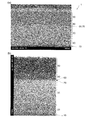
- (A), (b) is a cross-sectional STEM photograph of the lithium ion secondary battery of an Example. It is a cross-sectional STEM photograph of the lithium ion secondary battery of a comparative example.
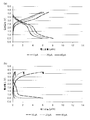
- (A) is a figure which shows the charging / discharging characteristic of the lithium ion secondary battery of an Example
- (b) is the figure which shows the charging / discharging characteristic of the lithium ion secondary battery of a comparative example, respectively.
- FIG. 1 is a diagram showing a cross-sectional configuration of a lithium ion secondary battery 1 to which the exemplary embodiment is applied.
- FIG. 2 is a view of the lithium ion secondary battery 1 to which the present embodiment is applied as viewed from above (II direction shown in FIG. 1).
- the lithium ion secondary battery 1 includes a substrate 10, a negative electrode layer 20 stacked on the substrate 10, a solid electrolyte layer 30 stacked on the negative electrode layer 20, and a positive electrode layer stacked on the solid electrolyte layer 30. 40 and a positive electrode current collector layer 50 laminated on the positive electrode layer 40.
- an intermediate layer 60 exists inside the solid electrolyte layer 30 at the boundary between the solid electrolyte layer 30 and the positive electrode layer 40, and the solid electrolyte layer 30 and the intermediate layer 60 are separated from each other.
- a mixed layer 70 exists at the boundary.
- the substrate 10 has a square shape.
- the negative electrode layer 20 and the solid electrolyte layer 30 laminated on the substrate 10 also have a square shape, and both have the same size (area).
- one side of the negative electrode layer 20 and the solid electrolyte layer 30 is shorter than one side of the substrate 10.
- the entire peripheral edges of the negative electrode layer 20 and the solid electrolyte layer 30 are located inside the entire peripheral edge of the substrate 10.
- the positive electrode layer 40 and the positive electrode current collector layer 50 laminated on the solid electrolyte layer 30 also have a square shape, and both have the same size (area).
- one side of the positive electrode layer 40 and the positive electrode current collector layer 50 is shorter than one side of the solid electrolyte layer 30.
- the entire peripheral edges of the positive electrode layer 40 and the positive electrode current collector layer 50 are located inside the entire peripheral edge of the solid electrolyte layer 30.
- the intermediate layer 60 and the mixed layer 70 existing inside the solid electrolyte layer 30 also have a square shape, and both have the same size (area). Further, one side of the intermediate layer 60 and the mixed layer 70 is substantially equal to one side of the positive electrode layer 40 (shorter than one side of the solid electrolyte layer 30).
- the entire periphery of the intermediate layer 60 and the mixed layer 70 is located on the inner side of the entire periphery of the solid electrolyte layer 30.
- the substrate 10 is used for loading a battery unit including the negative electrode layer 20, the solid electrolyte layer 30, the positive electrode layer 40, and the like. And it does not specifically limit as the board
- a stainless steel foil (plate) having higher mechanical strength than copper or aluminum is used as the substrate 10.
- a metal foil plated with a conductive metal such as tin, copper, or chromium may be used as the substrate 10.
- a negative electrode current collector layer having electron conductivity may be provided between the substrate 10 and the negative electrode layer 20.
- the thickness of the substrate 10 can be, for example, 20 ⁇ m or more and 200 ⁇ m or less. If the thickness of the substrate 10 is less than 20 ⁇ m, pinholes and tears are likely to occur during rolling and heat sealing when manufacturing a metal foil, and the electrical resistance value when used as a negative electrode increases. End up. On the other hand, when the thickness of the substrate 10 exceeds 200 ⁇ m, the volume energy density and the weight energy density are lowered due to the increase in the thickness and weight of the battery, and the flexibility of the lithium ion secondary battery 1 is lowered.
- the negative electrode layer 20 is a solid thin film, and includes a negative electrode active material that occludes lithium ions during charging and releases lithium ions during discharging.
- a negative electrode active material which comprises the negative electrode layer 20 carbon and silicon can be used, for example.
- Various dopants may be added to the negative electrode layer 20.
- the thickness of the negative electrode layer 20 can be, for example, 10 nm or more and 40 ⁇ m or less.
- the thickness of the negative electrode layer 20 is less than 10 nm, the capacity of the obtained lithium ion secondary battery 1 becomes too small and becomes impractical.
- the thickness of the negative electrode layer 20 exceeds 40 ⁇ m, it takes too much time to form the layer, and the productivity is lowered.
- the thickness of the negative electrode layer 20 may be more than 40 ⁇ m.
- the negative electrode layer 20 may have a crystal structure or may be an amorphous material having no crystal structure, but the expansion and contraction associated with insertion and extraction of lithium ions becomes more isotropic. In terms, it is preferably amorphous.
- a known film forming method such as various PVD (physical vapor deposition) and various CVD (chemical vapor deposition) may be used. From the viewpoint of production efficiency, a sputtering method may be used. It is desirable to use (sputtering).
- the solid electrolyte layer 30 is a solid thin film and includes a solid electrolyte (inorganic solid electrolyte) made of an inorganic material.
- the inorganic solid electrolyte constituting the solid electrolyte layer 30 is not particularly limited as long as it exhibits lithium ion conductivity, and is composed of various materials such as oxides, nitrides and sulfides. Can be used.
- the thickness of the solid electrolyte layer 30 can be, for example, 10 nm or more and 10 ⁇ m or less.
- the thickness of the solid electrolyte layer 30 is less than 10 nm, a short circuit (leakage) between the positive electrode layer 40 and the negative electrode layer 20 is likely to occur in the obtained lithium ion secondary battery 1.
- the thickness of the solid electrolyte layer 30 exceeds 10 ⁇ m, the moving distance of lithium ions becomes long and the charge / discharge rate becomes slow.
- the solid electrolyte layer 30 may have a crystal structure or may be an amorphous material having no crystal structure. Preferably there is.
- a known film forming method such as various PVDs and various CVDs may be used. From the viewpoint of production efficiency, it is desirable to use a sputtering method.
- the positive electrode layer 40 is a solid thin film, and includes a positive electrode active material that releases lithium ions during charging and occludes lithium ions during discharging.
- a positive electrode active material which comprises the positive electrode layer 40 1 type chosen from manganese (Mn), cobalt (Co), nickel (Ni), iron (Fe), molybdenum (Mo), vanadium (V), for example.
- a material composed of various materials such as oxides, sulfides, or phosphorus oxides containing the above metals can be used.
- the positive electrode active material in the positive electrode layer 40 is an inorganic solid in the solid electrolyte layer 30. It is desirable to contain an element heavier than the electrolyte.
- the thickness of the positive electrode layer 40 can be 10 nm or more and 40 ⁇ m or less, for example.
- the thickness of the positive electrode layer 40 is less than 10 nm, the capacity of the obtained lithium ion secondary battery 1 becomes too small and becomes impractical.
- the thickness of the positive electrode layer 40 exceeds 40 ⁇ m, it takes too much time to form the layer, and the productivity is lowered.
- the thickness of the positive electrode layer 40 may be more than 40 ⁇ m.
- the positive electrode layer 40 may have a crystal structure or an amorphous material having no crystal structure, but the expansion and contraction associated with insertion and extraction of lithium ions becomes more isotropic. In terms, it is preferably amorphous.
- a known film forming method such as various PVDs or various CVDs may be used, but it is desirable to use a sputtering method from the viewpoint of production efficiency.
- the positive electrode current collector layer 50 is not particularly limited as long as it is a solid thin film and has electron conductivity.
- a conductive material containing a metal such as (Pt) or gold (Au) or an alloy thereof can be used.
- the thickness of the positive electrode current collector layer 50 can be set to, for example, 5 nm or more and 50 ⁇ m or less. When the thickness of the positive electrode current collector layer 50 is less than 5 nm, the current collecting function is deteriorated and is not practical. On the other hand, if the thickness of the positive electrode current collector layer 50 exceeds 50 ⁇ m, it takes too much time to form the layer, and productivity is lowered.
- the positive electrode current collector layer 50 As a manufacturing method of the positive electrode current collector layer 50, a known film forming method such as various PVDs and various CVDs may be used, but from the viewpoint of production efficiency, a sputtering method or a vacuum evaporation method is used. Is desirable.
- the intermediate layer 60 is a solid thin film, and is located on the solid electrolyte layer 30 side in the boundary portion between the solid electrolyte layer 30 and the positive electrode layer 40.
- the intermediate layer 60 includes the constituent material of the inorganic solid electrolyte in the solid electrolyte layer 30 and the constituent material of the positive electrode active material in the positive electrode layer 40.
- the inorganic solid electrolyte of the solid electrolyte layer 30 is LiPON (compound of lithium, phosphorus, oxygen and nitrogen)
- the positive electrode active material of the positive electrode layer 40 is LiMnO (compound of lithium, manganese and oxygen)
- the intermediate layer 60 will contain lithium, phosphorus, manganese, oxygen and nitrogen.
- the positive electrode active material constituting the positive electrode layer 40 is mixed with other materials without forming a compound and maintaining itself. More specifically, the intermediate layer 60 of the present embodiment has a matrix (matrix) composed of a constituent material of the inorganic solid electrolyte in the solid electrolyte layer 30 and a constituent material of the positive electrode active material in the positive electrode layer 40.
- the positive electrode active material constituting the positive electrode layer 40 has a structure in which fillers (particles) are dispersed.
- the thickness of the intermediate layer 60 can be, for example, not less than 10 nm and not more than 100 nm. When the thickness of the intermediate layer 60 is less than 10 nm, the internal resistance of the obtained lithium ion secondary battery 1 becomes too high and becomes impractical. On the other hand, when the thickness of the intermediate layer 60 exceeds 100 nm, the insulation resistance between the positive electrode and the negative electrode expected for the solid electrolyte layer 30 decreases.
- the intermediate layer 60 may have a crystal structure or may be an amorphous material having no crystal structure, but is amorphous in that the expansion and contraction due to heat becomes more isotropic. It is preferable.
- the intermediate layer 60 may be manufactured independently, but from the viewpoint of production efficiency, in the manufacturing process of the solid electrolyte layer 30 and the positive electrode layer 40, a secondary intermediate layer 60 may be used. It is desirable to produce layer 60.
- the mixed layer 70 is located at the boundary between the solid electrolyte layer 30 and the intermediate layer 60.
- the inorganic solid electrolyte forming the solid electrolyte layer 30 and the positive electrode active material forming the positive electrode layer 40 are mixed in a state where they are maintained. More specifically, in the mixed layer 70, one (for example, an inorganic solid electrolyte) serves as a matrix (base material), and the other (for example, a positive electrode active material) serves as a filler (particles).
- a mixed layer 70 includes a region made of LiPON and a region made of LiMnO.
- the thickness of the mixed layer 70 can be, for example, not less than 10 nm and not more than 200 nm. If the thickness of the mixed layer 70 is less than 10 nm, the effect of reducing the interface resistance is poor. On the other hand, when the thickness of the mixed layer 70 exceeds 200 nm, the insulation resistance between the positive electrode and the negative electrode expected for the solid electrolyte layer 30 decreases.
- the mixed layer 70 may have a crystal structure or may be amorphous without a crystal structure, but is amorphous in that the expansion and contraction due to heat becomes more isotropic. It is preferable.
- the mixed layer 70 may be manufactured independently, but from the viewpoint of production efficiency, it is mixed in the manufacturing process of the solid electrolyte layer 30 and the positive electrode layer 40. It is desirable to produce layer 70.
- the negative electrode of the DC power source is connected to the substrate 10 functioning as the negative electrode current collector layer, and the positive electrode of the DC power source is connected to the positive electrode current collector layer 50, respectively. Is done. Then, lithium ions constituting the positive electrode active material in the positive electrode layer 40 move to the negative electrode layer 20 through the solid electrolyte layer 30 and are accommodated in the negative electrode active material in the negative electrode layer 20.
- the substrate 10 functioning as the negative electrode current collector layer has a direct current load negative electrode
- the positive current collector layer 50 has a direct current load positive electrode
- Each is connected.
- lithium ions contained in the negative electrode active material in the negative electrode layer 20 move to the positive electrode layer 40 through the solid electrolyte layer 30, and the positive electrode layer 40 constitutes the positive electrode active material.
- the entire periphery of the negative electrode layer 20 and the entire periphery of the solid electrolyte layer 30 are arranged and arranged in a solid state.
- the entire periphery of the positive electrode layer 40 is arranged inside the entire periphery of the electrolyte layer 30. Accordingly, in the lithium ion secondary battery 1, the negative electrode layer 20 and the positive electrode layer 40 are configured to be difficult to directly contact without passing through the solid electrolyte layer 30, and leakage in the lithium ion secondary battery 1 is caused. Is suppressed.
- FIG. 3 is a flowchart for explaining a manufacturing method of the lithium ion secondary battery 1.
- a substrate 10 is prepared and a preparation process for mounting on a sputtering apparatus (not shown) is executed (step 10).
- a negative electrode layer forming step for forming the negative electrode layer 20 on the substrate 10 is performed by the sputtering apparatus (step 20).
- a solid electrolyte layer forming step for forming the solid electrolyte layer 30 on the negative electrode layer 20 is performed by the sputtering apparatus (step 30).
- a positive electrode layer forming step for forming the positive electrode layer 40 on the solid electrolyte layer 30 is performed by the sputtering apparatus (step 40).
- the intermediate layer 60 and the mixed layer 70 are formed inside the solid electrolyte layer 30.
- the positive electrode layer 40 in order to form the intermediate layer 60 and the mixed layer 70 inside the solid electrolyte layer 30, the positive electrode layer 40 is formed at a rate of 0.5 nm / second to 50 nm / second, more preferably 1 nm / second to 10 nm / second is preferable. By setting it as said formation speed, the thickness of the intermediate
- the positive electrode current collector layer forming step of forming the positive electrode current collector layer 50 on the positive electrode layer 40 is performed by the sputtering apparatus (step 50). Then, the lithium ion secondary battery 1 having the negative electrode layer 20, the solid electrolyte layer 30, the positive electrode layer 40, and the positive electrode current collector layer 50 laminated on the substrate 10 and further having the intermediate layer 60 and the mixed layer 70, An extraction step of taking out from the sputtering apparatus is executed (step 60).
- the present invention is not limited to this. That is, if at least the mixed layer 70 is formed at the boundary between the solid electrolyte layer 30 and the positive electrode layer 40, the positive electrode layer 40, the solid electrolyte layer 30, and the negative electrode layer 20 are stacked in this order on the substrate 10.
- the configuration described above may be adopted.
- a negative electrode current collector layer made of a solid thin film having electron conductivity may be provided on the negative electrode layer 20.
- the present inventor produced two types of lithium ion secondary batteries, and evaluated each of the cross-sectional structure and the discharge capacity.
- the lithium ion secondary battery 1 (see FIG. 1) having the stacked structure described in the above embodiment was used.
- the lithium ion secondary battery 2 described below was used.
- FIG. 4 is a diagram showing a cross-sectional configuration of the lithium ion secondary battery 2 of the comparative example.
- the lithium ion secondary battery 2 includes a substrate 10, a positive electrode layer 40 stacked on the substrate 10, a solid electrolyte layer 30 stacked on the positive electrode layer 40, and a negative electrode layer stacked on the solid electrolyte layer 30. 20 and a negative electrode current collector layer 80 laminated on the negative electrode layer 20.
- the lithium ion secondary battery 2 of the comparative example is different from the lithium ion secondary battery 1 of the embodiment shown in FIG. 1 in that the positions of the negative electrode layer 20 and the positive electrode layer 40 are interchanged. Further, the lithium ion secondary battery 2 of the comparative example is different from the lithium ion secondary battery 1 of the example in that a negative electrode current collector layer 80 is provided instead of the positive electrode current collector layer 50. Furthermore, the lithium ion secondary battery 2 of the comparative example is different from the lithium ion secondary battery 1 of the example in that the intermediate layer 60 and the mixed layer 70 are not present between the solid electrolyte layer 30 and the positive electrode layer 40. Is different.
- the substrate 10 As the substrate 10, the negative electrode layer 20, the solid electrolyte layer 30, and the positive electrode layer 40, the same materials as those described in the embodiment can be used. Moreover, the same thing as what was demonstrated in the positive electrode collector layer 50 of embodiment can be used for the negative electrode collector layer 80.
- FIG. 1 As the substrate 10, the negative electrode layer 20, the solid electrolyte layer 30, and the positive electrode layer 40, the same materials as those described in the embodiment can be used. Moreover, the same thing as what was demonstrated in the positive electrode collector layer 50 of embodiment can be used for the negative electrode collector layer 80.
- Table 1 shows the production conditions of the lithium ion secondary battery 1 of the example. More specifically, Table 1 shows the relationship between the member names of the respective parts of the lithium ion secondary battery 1 of the example and the configuration (material, size, thickness, and structure) of each member.
- the intermediate layer 60 and the mixed layer 70 provided in the lithium ion secondary battery 1 of the embodiment are generated secondarily when the positive electrode layer 40 is laminated on the solid electrolyte layer 30. The description is omitted here.
- the lithium ion secondary battery 1 of the example will be described.
- SUS304 was used as the substrate 10.
- substrate 10 was 50 mm x 50 mm, and the thickness was 30 micrometers.
- the negative electrode layer 20 was formed using a sputtering method.
- silicon (Si) to which boron (B) was added was used as a sputtering target.
- Si (B) is shown.
- film formation was performed by DC sputtering.
- the atmosphere in the chamber was Ar
- the gas pressure in the chamber was 0.8 Pa
- the sputtering power was 500 W.
- the mask was arrange
- the solid electrolyte layer 30 was formed using a sputtering method.
- LiPON Li a PO b N c
- the film was formed by AC sputtering.
- the atmosphere in the chamber was N 2
- the gas pressure in the chamber was 0.5 Pa
- the sputtering power was 500 W.
- the mask was arrange
- the positive electrode layer 40 was formed using a sputtering method.
- Li 1.5 Mn 2 O 4 containing Li, Mn, and O was used as a sputtering target. Note that Li 1.5 Mn 2 O 4 does not satisfy the stoichiometric composition, unlike LiMn 2 O 4 and Li 2 Mn 2 O 4 widely used as the positive electrode active material.
- the film was formed by DC sputtering. At this time, the atmosphere in the chamber was Ar / O 2 , the gas pressure in the chamber was 0.5 Pa, and the sputtering power was 500 W.
- the mask was arrange
- the intermediate layer 60 and the mixed layer 70 are also formed during this period, and details thereof will be described later.
- the positive electrode current collector layer 50 was formed by sputtering.
- titanium (Ti) was used as a sputtering target.
- a film was formed by a DC sputtering method.
- the atmosphere in the chamber was Ar
- the gas pressure in the chamber was 0.8 Pa
- the sputtering power was 500 W.
- the mask was arrange
- the lithium ion secondary battery 1 of the example obtained in this way was analyzed by X-ray diffraction (XRD).
- XRD X-ray diffraction
- the substrate 10 and the positive electrode current collector layer 50 were crystallized.
- the negative electrode layer 20, the solid electrolyte layer 30, and the positive electrode layer 40 were amorphized.
- the intermediate layer 60 and the mixed layer 70 existing between the solid electrolyte layer 30 and the positive electrode layer 40 were also made amorphous.
- Table 2 shows the manufacturing conditions of the lithium ion secondary battery 2 of the comparative example. More specifically, Table 2 shows the relationship between the member names of the respective parts constituting the lithium ion secondary battery 2 of the comparative example and the configuration (material, thickness, size and structure) of each member. Yes.
- the manufacturing method of the lithium ion secondary battery 2 of the comparative example will be described.
- SUS304 was used as the substrate 10.
- the size (50 mm ⁇ 50 mm) and thickness (30 ⁇ m) of the substrate 10 were the same as those in the example.
- the positive electrode layer 40, the solid electrolyte layer 30, and the negative electrode layer 20 were formed in this order using a sputtering method.
- the production conditions of the positive electrode layer 40, the solid electrolyte layer 30, and the negative electrode layer 20 were basically the same as those in the example.
- the negative electrode current collector layer 80 was formed by sputtering.
- the production conditions of the negative electrode current collector layer 80 were basically the same as those of the positive electrode current collector layer 50 in the example. However, in the production of the lithium ion secondary battery 2 of the comparative example, the size of the positive electrode layer 40 and the solid electrolyte layer 30 is 10 mm ⁇ 10 mm, and the size of the negative electrode layer 20 and the negative electrode current collector layer 80 is 8 mm ⁇ 8 mm. did.
- the comparative lithium ion secondary battery 2 thus obtained was analyzed by X-ray diffraction (XRD). As a result, the substrate 10 and the negative electrode current collector layer 80 were crystallized. On the other hand, the positive electrode layer 40, the solid electrolyte layer 30, and the negative electrode layer 20 were amorphized.
- FIG. 5 is a cross-sectional STEM (Scanning Transmission Electron Microscope) photograph of the lithium ion secondary battery 1 of the example.
- FIG. 6 is a cross-sectional STEM photograph of the lithium ion secondary battery 2 of the comparative example.
- the magnification of FIG. 5A is 60,000 times
- the magnification of FIG. 5B is 100,000 times.
- the enlargement magnification in FIG. 6 is 60,000 times the same as that in FIG.
- STEM photographs were taken using an HD-2300 type ultra-thin film evaluation apparatus manufactured by Hitachi High-Technologies Corporation.
- the STEM is characterized in that an image reflecting the composition information can be obtained. More specifically, in the STEM, a region in which a heavy element exists is displayed in a relatively blackish color, and a region in which a light element exists is displayed in a relatively whitish color. Since lithium is the next lightest element after hydrogen and helium, the region where lithium is present in the STEM photographs shown in FIGS. 5 and 6 is displayed as whitish.
- the uppermost region is black because W (tungsten) attached to each sample is visible when the STEM photograph is taken. Because.
- the lithium ion secondary battery 1 shown in FIG. 5A has a cross-sectional structure in which a substrate 10, a negative electrode layer 20, a solid electrolyte layer 30, a positive electrode layer 40, and a positive electrode current collector layer 50 are stacked in this order. have.
- a layer having a concentration different from that of the solid electrolyte layer 30 and the positive electrode layer 40 exists at the boundary between the solid electrolyte layer 30 and the positive electrode layer 40.
- a layer having a concentration different from that of the solid electrolyte layer 30 and the positive electrode layer 40 exists at the boundary between the solid electrolyte layer 30 and the positive electrode layer 40.
- the layer existing between the solid electrolyte layer 30 and the positive electrode layer 40 is a layer having a uniform concentration located on the positive electrode layer 40 side, and the solid electrolyte layer 30. It can be classified into a layer having a nonuniform (mottled) density located on the side. Among these, the layer having a uniform concentration is the intermediate layer 60, and the layer having a non-uniform concentration is the mixed layer 70.
- 5B shows that the intermediate layer 60 has an intermediate concentration between the solid electrolyte layer 30 and the positive electrode layer 40.
- the mixed layer 70 has a base material having the same concentration as the solid electrolyte layer 30 and particles having the same concentration as the positive electrode layer 40 dispersed in the base material. However, particles having the same concentration as the positive electrode layer 40 are also present in the intermediate layer 60. From the STEM photograph shown in FIG. 5B, the thickness of the intermediate layer 60 was about 30 nm. The thickness of the mixed layer 70 was about 50 nm.
- the relative concentration in the positive electrode current collector layer 50 was high, and in other cases, the relative concentration was low. This is due to the fact that the positive electrode current collector layer 50 is made of titanium.
- the relative concentration in the negative electrode layer 20 was high, and in other cases, the relative concentration was low. This is due to the fact that the negative electrode layer 20 is composed mainly of silicon.
- the intermediate layer 60 and the mixed layer 70 are composed of the constituent materials (lithium, phosphorus, oxygen and nitrogen) of the solid electrolyte layer 30 and the constituent materials of the positive electrode layer 40 (lithium, manganese and oxygen). It became clear that it included.
- the lithium ion secondary battery 2 shown in FIG. 6 has a cross-sectional structure in which a substrate 10, a positive electrode layer 40, a solid electrolyte layer 30, a negative electrode layer 20, and a negative electrode current collector layer 80 are stacked in this order. ing. However, the intermediate layer 60 and the mixed layer 70 are not present at the boundary between the positive electrode layer 40 and the solid electrolyte layer 30 in the lithium ion secondary battery 2 as in the lithium ion secondary battery 1 of the embodiment. .
- the reason why the intermediate layer 60 and the mixed layer 70 are formed in the lithium ion secondary battery 1 of the embodiment is not formed in the lithium ion secondary battery 2 of the comparative example is as follows. It is estimated to be.
- LiPON is used as the inorganic solid electrolyte constituting the solid electrolyte layer 30, while Li 1.5 Mn 2 O 4 is used as the positive electrode active material constituting the positive electrode layer 40. Then, manganese as the heaviest element among the elements constituting the Li 1.5 Mn 2 O 4 (Mn ) is heavier than phosphorus (P) as the heaviest element among the elements constituting the LiPON.
- the positive electrode layer 40 is formed on the solid electrolyte layer 30 by sputtering. For this reason, when each element constituting the positive electrode active material collides with the solid electrolyte layer 30 that has already been laminated, the positive electrode active material containing manganese is likely to enter the solid electrolyte layer 30. As a result, it is considered that the intermediate layer 60 and the mixed layer 70 are formed between the solid electrolyte layer 30 and the positive electrode layer 40.
- the solid electrolyte layer 30 is formed on the positive electrode layer 40 by using the sputtering method. For this reason, when each element which comprises an inorganic solid electrolyte is made to collide with the positive electrode layer 40 already laminated
- the charge / discharge characteristics were measured for each of the lithium ion secondary battery 1 of the example and the lithium ion secondary battery 2 of the comparative example.
- a charge / discharge device HJ1020mSD8 manufactured by Hokuto Denko Co., Ltd. was used as a measurement device for charge / discharge characteristics.
- the current during charging (charging current) and the current during discharging (discharging current) were 10 ⁇ A, 20 ⁇ A, and 40 ⁇ A, respectively.
- FIG. 7A is a diagram showing the charge / discharge characteristics of the lithium ion secondary battery 1 of the example.
- FIG.7 (b) is a figure which shows the charging / discharging characteristic of the lithium ion secondary battery 2 of a comparative example.
- the horizontal axis represents the battery capacity ( ⁇ Ah)
- the vertical axis represents the battery voltage (V).
- the charging characteristic is rising to the right in the figure, and the discharging characteristic is falling to the right in the figure.
- the negative electrode layer 20, the solid electrolyte layer 30, and the positive electrode layer 40 are composed of the same material and the same thickness.
- the lithium ion secondary battery 2 of the comparative example has a steep increase in battery voltage compared to the lithium ion secondary battery 1 of the example. ing.
- the lithium ion secondary battery 2 of the comparative example has a smaller battery capacity at the completion of charging than the lithium ion secondary battery 1 of the example.
- the battery voltage at the time of discharging is sharper than that of the lithium ion secondary battery 1 of the example.
- the lithium ion secondary battery 1 of the example has an increased battery capacity, that is, a charge capacity and a discharge capacity, as compared with the lithium ion secondary battery 2 of the comparative example.
- Such a difference is considered to be caused by the internal resistance of the lithium ion secondary battery 1 of the example being lower than that of the lithium ion secondary battery 2 of the comparative example.
- the lithium ion secondary battery 1 of the example since the mixed layer 70 and the like are provided at the boundary between the solid electrolyte layer 30 and the positive electrode layer 40, the lithium ion of the comparative example that does not have the mixed layer 70 and the like. It is considered that the internal resistance is lower than that of the secondary battery 2.
Landscapes
- Chemical & Material Sciences (AREA)
- General Chemical & Material Sciences (AREA)
- Chemical Kinetics & Catalysis (AREA)
- Electrochemistry (AREA)
- Engineering & Computer Science (AREA)
- Manufacturing & Machinery (AREA)
- Materials Engineering (AREA)
- Inorganic Chemistry (AREA)
- Composite Materials (AREA)
- General Physics & Mathematics (AREA)
- Condensed Matter Physics & Semiconductors (AREA)
- Physics & Mathematics (AREA)
- Secondary Cells (AREA)
- Battery Electrode And Active Subsutance (AREA)
Abstract
リチウムイオン二次電池1は、ステンレス製の基板10と、負極活物質を含み且つ基板10に積層される負極層20と、リチウムイオン伝導性を示す無機固体電解質を含み且つ負極層20に積層される固体電解質層30と、正極活物質を含み且つ固体電解質層30に積層される正極層40と、チタンからなり正極層40に積層される正極集電体層50とを備える。リチウムイオン二次電池1における固体電解質層30と正極層40との境界部には、正極活物質と無機固体電解質とが混在する混在層70が設けられる。これらにより、全固体リチウムイオン二次電池の放電容量を増加させる。
Description
本発明は、リチウムイオン二次電池およびリチウムイオン二次電池の製造方法に関する。
携帯電話やノート型パソコンなどの携帯電子機器の普及に伴い、高いエネルギー密度を有する、小型で軽量な二次電池の開発が強く望まれている。このような要求を満たす二次電池として、リチウムイオン二次電池が知られている。リチウムイオン二次電池は、正極活物質を含む正極と、負極活物質を含む負極と、リチウムイオン伝導性を示し且つ正極および負極の間に配置される電解質とを有している。
従来のリチウムイオン二次電池では、電解質として有機電解液等が用いられてきた。これに対し、電解質として無機材料からなる固体電解質(無機固体電解質)を用いるとともに、負極、固体電解質および正極をすべて薄膜で構成した、全固体型且つ薄膜型のリチウムイオン二次電池が提案されている(特許文献1参照)。
ここで、リチウムイオン二次電池には、内部抵抗を極力下げ、1回の充電当たりに外部に提供できる電池の容量を増やすことが、強く望まれている。
しかしながら、電解液を用いない全固体のリチウムイオン二次電池では、固体電解質と正極との間の界面にリチウムイオン伝導度が低い領域が発生し、電解液電池よりも電池の放電容量が低くなることがあった。
本発明は、全固体リチウムイオン二次電池の放電容量を増加させることを目的とする。
しかしながら、電解液を用いない全固体のリチウムイオン二次電池では、固体電解質と正極との間の界面にリチウムイオン伝導度が低い領域が発生し、電解液電池よりも電池の放電容量が低くなることがあった。
本発明は、全固体リチウムイオン二次電池の放電容量を増加させることを目的とする。
本発明のリチウムイオン二次電池は、正極活物質を含む正極層と、負極活物質を含む負極層と、リチウムイオン伝導性を示す無機固体電解質を含み且つ前記正極層と前記負極層との間に設けられる固体電解質層と、前記正極活物質と前記無機固体電解質とが混在し、前記正極層と前記固体電解質層との間に設けられる混在層とを有している。
このようなリチウムイオン二次電池において、前記正極活物質は、前記無機固体電解質よりも重い元素を含んでいることを特徴とすることができる。
また、前記混在層では、前記無機固体電解質からなる母材に、前記正極活物質からなる粒子が分散していることを特徴とすることができる。
さらに、前記正極層と前記混在層との境界部には、前記正極活物質の構成材料と前記無機固体電解質の構成材料とを含み、さらに当該正極活物質が混在する中間層が設けられることを特徴とすることができる。
そして、前記負極層、前記中間層および前記正極層を、この順で積層する基板をさらに有することを特徴とすることができる。
また、他の観点から捉えると、本発明のリチウムイオン二次電池の製造方法は、負極活物質を含む負極層を形成する負極層形成工程と、前記負極層の上に、リチウムイオン伝導性を示す無機固体電解質を含む固体電解質層を形成する固体電解質層形成工程と、前記固体電解質層の上に、正極活物質と前記無機固体電解質とが混在する混在層を形成するとともに、当該混在層の上に、当該正極活物質を含む正極層を形成する正極層形成工程とを有している。
このようなリチウムイオン二次電池の製造方法において、前記正極層形成工程では、スパッタ法にて前記混在層および前記正極層を形成し、前記正極活物質は、前記無機固体電解質よりも重い元素を含んでいることを特徴とすることができる。
また、前記正極層形成工程では、前記混在層の上に、前記正極活物質の構成材料と前記無機固体電解質の構成材料とを含み、さらに当該正極活物質が混在する中間層をさらに形成することを特徴とすることができる。
このようなリチウムイオン二次電池において、前記正極活物質は、前記無機固体電解質よりも重い元素を含んでいることを特徴とすることができる。
また、前記混在層では、前記無機固体電解質からなる母材に、前記正極活物質からなる粒子が分散していることを特徴とすることができる。
さらに、前記正極層と前記混在層との境界部には、前記正極活物質の構成材料と前記無機固体電解質の構成材料とを含み、さらに当該正極活物質が混在する中間層が設けられることを特徴とすることができる。
そして、前記負極層、前記中間層および前記正極層を、この順で積層する基板をさらに有することを特徴とすることができる。
また、他の観点から捉えると、本発明のリチウムイオン二次電池の製造方法は、負極活物質を含む負極層を形成する負極層形成工程と、前記負極層の上に、リチウムイオン伝導性を示す無機固体電解質を含む固体電解質層を形成する固体電解質層形成工程と、前記固体電解質層の上に、正極活物質と前記無機固体電解質とが混在する混在層を形成するとともに、当該混在層の上に、当該正極活物質を含む正極層を形成する正極層形成工程とを有している。
このようなリチウムイオン二次電池の製造方法において、前記正極層形成工程では、スパッタ法にて前記混在層および前記正極層を形成し、前記正極活物質は、前記無機固体電解質よりも重い元素を含んでいることを特徴とすることができる。
また、前記正極層形成工程では、前記混在層の上に、前記正極活物質の構成材料と前記無機固体電解質の構成材料とを含み、さらに当該正極活物質が混在する中間層をさらに形成することを特徴とすることができる。
本発明によれば、正極層と固体電解質層とを直接接触させる場合と比較して、全固体リチウムイオン二次電池の放電容量を増加させることができる。
以下、添付図面を参照して、本発明の実施の形態について詳細に説明する。なお、以下の説明で参照する図面における各部の大きさや厚さ等は、実際の寸法とは異なっている場合がある。
[リチウムイオン二次電池の構成]
図1は、本実施の形態が適用されるリチウムイオン二次電池1の断面構成を示す図である。また、図2は、本実施の形態が適用されるリチウムイオン二次電池1を上方(図1に示すII方向)からみた図である。
図1は、本実施の形態が適用されるリチウムイオン二次電池1の断面構成を示す図である。また、図2は、本実施の形態が適用されるリチウムイオン二次電池1を上方(図1に示すII方向)からみた図である。
このリチウムイオン二次電池1は、基板10と、基板10上に積層される負極層20と、負極層20上に積層される固体電解質層30と、固体電解質層30上に積層される正極層40と、正極層40上に積層される正極集電体層50とを備えている。また、このリチウムイオン二次電池1のうち、固体電解質層30と正極層40との境界部における固体電解質層30の内部には中間層60が存在し、固体電解質層30と中間層60との境界部には混在層70が存在している。
本実施の形態において、基板10は正方形状を呈している。
また、基板10上に積層される負極層20および固体電解質層30も正方形状を呈しており、両者は同じ大きさ(面積)となっている。ただし、これら負極層20および固体電解質層30の一辺は、基板10の一辺よりも短くなっている。そして、負極層20および固体電解質層30の全周縁は、基板10の全周縁よりも内側に位置している。
さらに、固体電解質層30上に積層される正極層40および正極集電体層50も正方形状を呈しており、両者は同じ大きさ(面積)となっている。ただし、これら正極層40および正極集電体層50の一辺は、固体電解質層30の一辺よりも短くなっている。そして、正極層40および正極集電体層50の全周縁は、固体電解質層30の全周縁よりも内側に位置している。
なお、固体電解質層30の内部に存在する中間層60および混在層70も正方形状を呈しており、両者は同じ大きさ(面積)となっている。また、これら中間層60および混在層70の一辺は、正極層40の一辺とほぼ等しく(固体電解質層30の一辺よりも短く)なっている。そして、中間層60および混在層70の全周縁は、固体電解質層30の全周縁よりも内側に位置している。
また、基板10上に積層される負極層20および固体電解質層30も正方形状を呈しており、両者は同じ大きさ(面積)となっている。ただし、これら負極層20および固体電解質層30の一辺は、基板10の一辺よりも短くなっている。そして、負極層20および固体電解質層30の全周縁は、基板10の全周縁よりも内側に位置している。
さらに、固体電解質層30上に積層される正極層40および正極集電体層50も正方形状を呈しており、両者は同じ大きさ(面積)となっている。ただし、これら正極層40および正極集電体層50の一辺は、固体電解質層30の一辺よりも短くなっている。そして、正極層40および正極集電体層50の全周縁は、固体電解質層30の全周縁よりも内側に位置している。
なお、固体電解質層30の内部に存在する中間層60および混在層70も正方形状を呈しており、両者は同じ大きさ(面積)となっている。また、これら中間層60および混在層70の一辺は、正極層40の一辺とほぼ等しく(固体電解質層30の一辺よりも短く)なっている。そして、中間層60および混在層70の全周縁は、固体電解質層30の全周縁よりも内側に位置している。
次に、上記リチウムイオン二次電池1の各構成要素について、より詳細な説明を行う。
(基板)
基板10は、負極層20、固体電解質層30および正極層40等を含む電池部を積載するために用いられる。そして、基板10としては、特に限定されず、金属、ガラス、セラミックスなど、各種材料で構成されたものを用いることができる。
本実施の形態では、基板10を、リチウムイオン二次電池1における負極集電体層としても機能させる目的で、電子伝導性を有する金属製の板材で構成している。より具体的に説明すると、本実施の形態では、基板10として、銅やアルミニウム等と比較して機械的強度が高いステンレス箔(板)を用いている。また、基板10として、錫、銅、クロム等の導電性金属でめっきした金属箔を用いてもよい。なお、基板10として絶縁性を有する材料を用いる場合には、基板10と負極層20との間に、電子伝導性を有する負極集電体層を設けるとよい。
(基板)
基板10は、負極層20、固体電解質層30および正極層40等を含む電池部を積載するために用いられる。そして、基板10としては、特に限定されず、金属、ガラス、セラミックスなど、各種材料で構成されたものを用いることができる。
本実施の形態では、基板10を、リチウムイオン二次電池1における負極集電体層としても機能させる目的で、電子伝導性を有する金属製の板材で構成している。より具体的に説明すると、本実施の形態では、基板10として、銅やアルミニウム等と比較して機械的強度が高いステンレス箔(板)を用いている。また、基板10として、錫、銅、クロム等の導電性金属でめっきした金属箔を用いてもよい。なお、基板10として絶縁性を有する材料を用いる場合には、基板10と負極層20との間に、電子伝導性を有する負極集電体層を設けるとよい。
基板10の厚さは、例えば20μm以上200μm以下とすることができる。基板10の厚さが20μm未満であると、金属箔を製造する際の圧延時や熱封止時にピンホールや破れが生じやすく、また、負の電極として用いる場合の電気抵抗値が高くなってしまう。一方、基板10の厚さが200μmを超えると、電池の厚さおよび重量の増加により体積エネルギー密度および重量エネルギー密度が低下し、また、リチウムイオン二次電池1の柔軟性が低下する。
(負極層)
負極層20は、固体薄膜であって、充電時にはリチウムイオンを吸蔵するとともに放電時にはリチウムイオンを放出する負極活物質を含んでいる。ここで、負極層20を構成する負極活物質としては、例えば、炭素やシリコンを用いることができる。また、負極層20には、各種ドーパントを添加してもよい。
負極層20は、固体薄膜であって、充電時にはリチウムイオンを吸蔵するとともに放電時にはリチウムイオンを放出する負極活物質を含んでいる。ここで、負極層20を構成する負極活物質としては、例えば、炭素やシリコンを用いることができる。また、負極層20には、各種ドーパントを添加してもよい。
負極層20の厚さは、例えば10nm以上40μm以下とすることができる。負極層20の厚さが10nm未満であると、得られるリチウムイオン二次電池1の容量が小さくなりすぎ、実用的ではなくなる。一方、負極層20の厚さが40μmを超えると、層形成に時間がかかりすぎるようになってしまい、生産性が低下する。ただし、リチウムイオン二次電池1に要求される電池容量が大きい場合には、負極層20の厚さを40μm超としてもかまわない。
また、負極層20は、結晶構造を持つものであっても、結晶構造を持たないアモルファスであってもかまわないが、リチウムイオンの吸蔵および放出に伴う膨張および収縮がより等方的になるという点で、アモルファスであることが好ましい。
さらに、負極層20の製造方法としては、各種PVD(物理的蒸着)や各種CVD(化学的蒸着)など、公知の成膜手法を用いてかまわないが、生産効率の観点からすれば、スパッタ法(スパッタリング)を用いることが望ましい。
(固体電解質層)
固体電解質層30は、固体薄膜であって、無機材料からなる固体電解質(無機固体電解質)を含んでいる。固体電解質層30を構成する無機固体電解質については、リチウムイオン伝導性を示すものであれば、特に限定されるものではなく、酸化物、窒化物、硫化物など、各種材料で構成されたものを用いることができる。
固体電解質層30は、固体薄膜であって、無機材料からなる固体電解質(無機固体電解質)を含んでいる。固体電解質層30を構成する無機固体電解質については、リチウムイオン伝導性を示すものであれば、特に限定されるものではなく、酸化物、窒化物、硫化物など、各種材料で構成されたものを用いることができる。
固体電解質層30の厚さは、例えば10nm以上10μm以下とすることができる。固体電解質層30の厚さが10nm未満であると、得られたリチウムイオン二次電池1において、正極層40と負極層20との間での短絡(リーク)が生じやすくなる。一方、固体電解質層30の厚さが10μmを超えると、リチウムイオンの移動距離が長くなり、充放電速度が遅くなる。
また、固体電解質層30は、結晶構造を持つものであっても、結晶構造を持たないアモルファスであってもかまわないが、熱による膨張および収縮がより等方的になるという点で、アモルファスであることが好ましい。
さらに、固体電解質層30の製造方法としては、各種PVDや各種CVDなど、公知の成膜手法を用いてかまわないが、生産効率の観点からすれば、スパッタ法を用いることが望ましい。
(正極層)
正極層40は、固体薄膜であって、充電時にはリチウムイオンを放出するとともに放電時にはリチウムイオンを吸蔵する正極活物質を含んでいる。ここで、正極層40を構成する正極活物質としては、例えば、マンガン(Mn)、コバルト(Co)、ニッケル(Ni)、鉄(Fe)、モリブデン(Mo)、バナジウム(V)から選ばれる一種以上の金属を含む、酸化物、硫化物あるいはリン酸化物など、各種材料で構成されたものを用いることができる。ただし、固体電解質層30と正極層40との間に、より確実に中間層60および混在層70を形成するという観点からすれば、正極層40における正極活物質は、固体電解質層30における無機固体電解質よりも重い元素を含んでいることが望ましい。
正極層40は、固体薄膜であって、充電時にはリチウムイオンを放出するとともに放電時にはリチウムイオンを吸蔵する正極活物質を含んでいる。ここで、正極層40を構成する正極活物質としては、例えば、マンガン(Mn)、コバルト(Co)、ニッケル(Ni)、鉄(Fe)、モリブデン(Mo)、バナジウム(V)から選ばれる一種以上の金属を含む、酸化物、硫化物あるいはリン酸化物など、各種材料で構成されたものを用いることができる。ただし、固体電解質層30と正極層40との間に、より確実に中間層60および混在層70を形成するという観点からすれば、正極層40における正極活物質は、固体電解質層30における無機固体電解質よりも重い元素を含んでいることが望ましい。
正極層40の厚さは、例えば10nm以上40μm以下とすることができる。正極層40の厚さが10nm未満であると、得られるリチウムイオン二次電池1の容量が小さくなりすぎ、実用的ではなくなる。一方、正極層40の厚さが40μmを超えると、層形成に時間がかかりすぎるようになってしまい、生産性が低下する。ただし、リチウムイオン二次電池1に要求される電池容量が大きい場合には、正極層40の厚さを40μm超としてもかまわない。
また、正極層40は、結晶構造を持つものであっても、結晶構造を持たないアモルファスであってもかまわないが、リチウムイオンの吸蔵および放出に伴う膨張および収縮がより等方的になるという点で、アモルファスであることが好ましい。
さらに、正極層40の作製方法としては、各種PVDや各種CVDなど、公知の成膜手法を用いてかまわないが、生産効率の観点からすれば、スパッタ法を用いることが望ましい。
(正極集電体層)
正極集電体層50は、固体薄膜であって、電子伝導性を有するものであれば、特に限定されるものではなく、例えば、チタン(Ti)、アルミニウム(Al)、銅(Cu)、白金(Pt)、金(Au)などの金属や、これらの合金を含む導電性材料を用いることができる。
正極集電体層50は、固体薄膜であって、電子伝導性を有するものであれば、特に限定されるものではなく、例えば、チタン(Ti)、アルミニウム(Al)、銅(Cu)、白金(Pt)、金(Au)などの金属や、これらの合金を含む導電性材料を用いることができる。
正極集電体層50の厚さは、例えば5nm以上50μm以下とすることができる。正極集電体層50の厚さが5nm未満であると、集電機能が低下し、実用的ではなくなる。一方、正極集電体層50の厚さが50μmを超えると、層形成に時間がかかりすぎるようになってしまい、生産性が低下する。
また、正極集電体層50の製造方法としては、各種PVDや各種CVDなど、公知の成膜手法を用いてかまわないが、生産効率の観点からすれば、スパッタ法もしくは真空蒸着法を用いることが望ましい。
(中間層)
中間層60は、固体薄膜であって、固体電解質層30と正極層40との境界部のうち、固体電解質層30側に位置している。そして、中間層60は、固体電解質層30における無機固体電解質の構成材料と、正極層40における正極活物質の構成材料とを含んでいる。例えば、固体電解質層30の無機固体電解質がLiPON(リチウム、リン、酸素および窒素の化合物)であり、正極層40の正極活物質がLiMnO(リチウム、マンガンおよび酸素の化合物)である場合、中間層60は、リチウム、リン、マンガン、酸素および窒素を含んでいることになる。
中間層60は、固体薄膜であって、固体電解質層30と正極層40との境界部のうち、固体電解質層30側に位置している。そして、中間層60は、固体電解質層30における無機固体電解質の構成材料と、正極層40における正極活物質の構成材料とを含んでいる。例えば、固体電解質層30の無機固体電解質がLiPON(リチウム、リン、酸素および窒素の化合物)であり、正極層40の正極活物質がLiMnO(リチウム、マンガンおよび酸素の化合物)である場合、中間層60は、リチウム、リン、マンガン、酸素および窒素を含んでいることになる。
また、中間層60は、正極層40を構成する正極活物質が、他の材料と化合物を形成せず、自身を維持した状態で混在している。より具体的に説明すると、本実施の形態の中間層60は、固体電解質層30における無機固体電解質の構成材料と、正極層40における正極活物質の構成材料とからなるマトリックス(母材)に、正極層40を構成する正極活物質のフィラー(粒子)を分散した構造を有している。
中間層60の厚さは、例えば10nm以上100nm以下とすることができる。中間層60の厚さが10nm未満であると、得られるリチウムイオン二次電池1の内部抵抗が高くなりすぎ、実用的ではなくなる。一方中間層60の厚さが100nmを超えると、固体電解質層30に期待される正極と負極との間の絶縁耐性が低下することになる。
また、中間層60は、結晶構造を持つものであっても、結晶構造を持たないアモルファスであってもかまわないが、熱による膨張および収縮がより等方的になるという点で、アモルファスであることが好ましい。
さらに、中間層60の製造方法としては、独立して製造するようにしてもかまわないが、生産効率の観点からすれば、固体電解質層30および正極層40の製造過程において、副次的に中間層60を生成することが望ましい。
(混在層)
混在層70は、上述したように、固体電解質層30と中間層60との境界部に位置している。そして、混在層70は、固体電解質層30を構成する無機固体電解質と、正極層40を構成する正極活物質とが、それぞれを維持した状態で混在している。より具体的に説明すると、混在層70では、一方(例えば無機固体電解質)がマトリックス(母材)となり、他方(例えば正極活物質)がフィラー(粒子)となる。例えば、固体電解質層30の無機固体電解質がLiPON(リチウム、リン、酸素および窒素の化合物)であり、正極層40の正極活物質がLiMnO(リチウム、マンガンおよび酸素の化合物)である場合、混在層70は、LiPONからなる領域と、LiMnOからなる領域とを含んでいることになる。
混在層70は、上述したように、固体電解質層30と中間層60との境界部に位置している。そして、混在層70は、固体電解質層30を構成する無機固体電解質と、正極層40を構成する正極活物質とが、それぞれを維持した状態で混在している。より具体的に説明すると、混在層70では、一方(例えば無機固体電解質)がマトリックス(母材)となり、他方(例えば正極活物質)がフィラー(粒子)となる。例えば、固体電解質層30の無機固体電解質がLiPON(リチウム、リン、酸素および窒素の化合物)であり、正極層40の正極活物質がLiMnO(リチウム、マンガンおよび酸素の化合物)である場合、混在層70は、LiPONからなる領域と、LiMnOからなる領域とを含んでいることになる。
混在層70の厚さは、例えば10nm以上200nm以下とすることができる。混在層70の厚さが10nm未満であると、界面抵抗低減の効果が乏しくなる。一方、混在層70の厚さが200nmを超えると、固体電解質層30に期待される正極と負極との間の絶縁耐性が低下することになる。
また、混在層70は、結晶構造を持つものであっても、結晶構造を持たないアモルファスであってもかまわないが、熱による膨張および収縮がより等方的になるという点で、アモルファスであることが好ましい。
さらに、混在層70の製造方法としては、独立して製造するようにしてもかまわないが、生産効率の観点からすれば、固体電解質層30および正極層40の製造過程において、副次的に混在層70を生成することが望ましい。
[リチウムイオン二次電池の動作]
本実施の形態のリチウムイオン二次電池1を充電する場合、負極集電体層として機能する基板10には直流電源の負極が、正極集電体層50には直流電源の正極が、それぞれ接続される。そして、正極層40で正極活物質を構成するリチウムイオンが、固体電解質層30を介して負極層20へと移動し、負極層20で負極活物質に収容される。
本実施の形態のリチウムイオン二次電池1を充電する場合、負極集電体層として機能する基板10には直流電源の負極が、正極集電体層50には直流電源の正極が、それぞれ接続される。そして、正極層40で正極活物質を構成するリチウムイオンが、固体電解質層30を介して負極層20へと移動し、負極層20で負極活物質に収容される。
また、充電したリチウムイオン二次電池1を使用(放電)する場合、負極集電体層として機能する基板10には直流負荷の負極が、正極集電体層50には直流負荷の正極が、それぞれ接続される。そして、負極層20で負極活物質に収容されるリチウムイオンが、固体電解質層30を介して正極層40へと移動し、正極層40で正極活物質を構成する。
ここで、本実施の形態のリチウムイオン二次電池1では、図1および図2に示したように、負極層20の全周縁と固体電解質層30の全周縁とを揃えて配置するとともに、固体電解質層30の全周縁の内側に正極層40の全周縁を配置している。これにより、このリチウムイオン二次電池1では、負極層20および正極層40が、固体電解質層30を介さずに直接に接触し難い構成となっており、リチウムイオン二次電池1内でのリークを抑制している。
[リチウムイオン二次電池の作製方法]
次に、図1に示すリチウムイオン二次電池1の作製方法(製造方法)について説明を行う。
図3は、リチウムイオン二次電池1の作製方法を説明するためのフローチャートである。
次に、図1に示すリチウムイオン二次電池1の作製方法(製造方法)について説明を行う。
図3は、リチウムイオン二次電池1の作製方法を説明するためのフローチャートである。
まず、リチウムイオン二次電池1の作製に先立ち、基板10を準備するとともに図示しないスパッタ装置に装着する準備工程を実行する(ステップ10)。
次に、上記スパッタ装置にて、基板10上に、負極層20を形成する負極層形成工程を実行する(ステップ20)。
続いて、上記スパッタ装置にて、負極層20上に、固体電解質層30を形成する固体電解質層形成工程を実行する(ステップ30)。
次いで、上記スパッタ装置にて、固体電解質層30上に、正極層40を形成する正極層形成工程を実行する(ステップ40)。ここで、本実施の形態では、ステップ40の正極層形成工程において、正極層40に加えて、固体電解質層30の内部に中間層60および混在層70が形成される。
ステップ40の正極層形成工程において、固体電解質層30の内部に中間層60および混在層70を形成するためには、正極層40の形成速度を0.5nm/秒~50nm/秒、より好ましくは、1nm/秒~10nm/秒とすることが好ましい。上記の形成速度とすることで、中間層60および混在層70の厚さを適正な範囲にすることができる。
それから、上記スパッタ装置にて、正極層40上に、正極集電体層50を形成する正極集電体層形成工程を実行する(ステップ50)。
そして、基板10上に、負極層20、固体電解質層30、正極層40および正極集電体層50を積層してなり、さらに中間層60および混在層70も有するリチウムイオン二次電池1を、スパッタ装置から取り出す取出工程を実行する(ステップ60)。
次に、上記スパッタ装置にて、基板10上に、負極層20を形成する負極層形成工程を実行する(ステップ20)。
続いて、上記スパッタ装置にて、負極層20上に、固体電解質層30を形成する固体電解質層形成工程を実行する(ステップ30)。
次いで、上記スパッタ装置にて、固体電解質層30上に、正極層40を形成する正極層形成工程を実行する(ステップ40)。ここで、本実施の形態では、ステップ40の正極層形成工程において、正極層40に加えて、固体電解質層30の内部に中間層60および混在層70が形成される。
ステップ40の正極層形成工程において、固体電解質層30の内部に中間層60および混在層70を形成するためには、正極層40の形成速度を0.5nm/秒~50nm/秒、より好ましくは、1nm/秒~10nm/秒とすることが好ましい。上記の形成速度とすることで、中間層60および混在層70の厚さを適正な範囲にすることができる。
それから、上記スパッタ装置にて、正極層40上に、正極集電体層50を形成する正極集電体層形成工程を実行する(ステップ50)。
そして、基板10上に、負極層20、固体電解質層30、正極層40および正極集電体層50を積層してなり、さらに中間層60および混在層70も有するリチウムイオン二次電池1を、スパッタ装置から取り出す取出工程を実行する(ステップ60)。
[その他]
本実施の形態では、基板10上に、負極層20、固体電解質層30および正極層40を、この順番で積層した構成を採用しているがこれに限られるものではない。すなわち、固体電解質層30と正極層40との境界部に、少なくとも混在層70が形成されるものであれば、基板10上に、正極層40、固体電解質層30および負極層20の順で積層した構成を採用してもよい。また、この場合には、負極層20の上に、電子伝導性を有する固体薄膜からなる負極集電体層を設けるとよい。
本実施の形態では、基板10上に、負極層20、固体電解質層30および正極層40を、この順番で積層した構成を採用しているがこれに限られるものではない。すなわち、固体電解質層30と正極層40との境界部に、少なくとも混在層70が形成されるものであれば、基板10上に、正極層40、固体電解質層30および負極層20の順で積層した構成を採用してもよい。また、この場合には、負極層20の上に、電子伝導性を有する固体薄膜からなる負極集電体層を設けるとよい。
以下、実施例に基づいて本発明をさらに詳細に説明する。ただし、本発明は、その要旨を超えない限り、以下の実施例に限定されるものではない。
本発明者は、2種類のリチウムイオン二次電池を作製し、それぞれの断面構造と放電容量とに関する評価を行った。
本発明者は、2種類のリチウムイオン二次電池を作製し、それぞれの断面構造と放電容量とに関する評価を行った。
実施例では、上記実施の形態で説明した積層構造を有するリチウムイオン二次電池1(図1参照)を用いた。これに対し、比較例では、以下に説明するリチウムイオン二次電池2を用いた。
[比較例のリチウムイオン二次電池の構成]
図4は、比較例のリチウムイオン二次電池2の断面構成を示す図である。
このリチウムイオン二次電池2は、基板10と、基板10上に積層される正極層40と、正極層40上に積層される固体電解質層30と、固体電解質層30上に積層される負極層20と、負極層20上に積層される負極集電体層80とを備えている。
図4は、比較例のリチウムイオン二次電池2の断面構成を示す図である。
このリチウムイオン二次電池2は、基板10と、基板10上に積層される正極層40と、正極層40上に積層される固体電解質層30と、固体電解質層30上に積層される負極層20と、負極層20上に積層される負極集電体層80とを備えている。
このように、比較例のリチウムイオン二次電池2は、負極層20および正極層40の位置が入れ替わっている点で、図1に示す実施例のリチウムイオン二次電池1とは異なる。また、比較例のリチウムイオン二次電池2は、正極集電体層50に代えて負極集電体層80が設けられている点で、実施例のリチウムイオン二次電池1とは異なる。さらに、比較例のリチウムイオン二次電池2は、固体電解質層30と正極層40との間に中間層60および混在層70が存在していない点で、実施例のリチウムイオン二次電池1とは異なる。
ここで、基板10、負極層20、固体電解質層30および正極層40には、実施の形態で説明したものと同じものを用いることができる。また、負極集電体層80には、実施の形態の正極集電体層50で説明したものと同じものを用いることができる。
[実施例のリチウムイオン二次電池の作製方法]
では、実施例のリチウムイオン二次電池1の作製方法について説明を行う。
ここで、表1は、実施例のリチウムイオン二次電池1の作製条件を示している。より具体的に説明すると、表1は、実施例のリチウムイオン二次電池1の各部の部材名と、各部材の構成(材料、大きさ、厚さおよび構造)との関係を示している。ただし、実施例のリチウムイオン二次電池1に設けられる中間層60および混在層70については、固体電解質層30上に正極層40を積層する際に副次的に生成されるものであることから、ここでは記載を省略している。
では、実施例のリチウムイオン二次電池1の作製方法について説明を行う。
ここで、表1は、実施例のリチウムイオン二次電池1の作製条件を示している。より具体的に説明すると、表1は、実施例のリチウムイオン二次電池1の各部の部材名と、各部材の構成(材料、大きさ、厚さおよび構造)との関係を示している。ただし、実施例のリチウムイオン二次電池1に設けられる中間層60および混在層70については、固体電解質層30上に正極層40を積層する際に副次的に生成されるものであることから、ここでは記載を省略している。
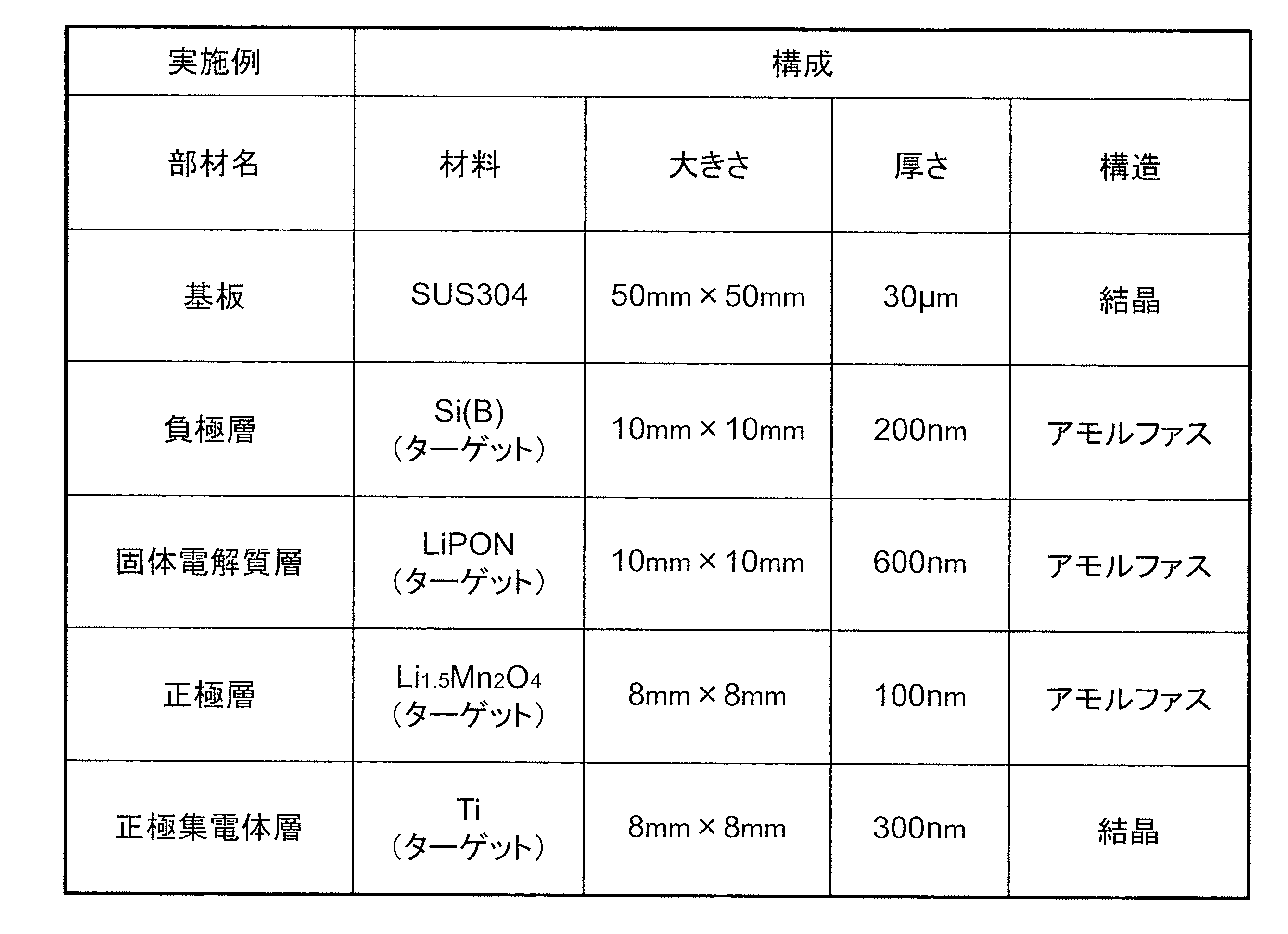
では、図1および表1を参照しつつ、実施例のリチウムイオン二次電池1の作製方法について説明を行う。
実施例では、基板10としてSUS304を用いた。そして、基板10の大きさは50mm×50mmとし、その厚さは30μmとした。
実施例では、基板10としてSUS304を用いた。そして、基板10の大きさは50mm×50mmとし、その厚さは30μmとした。
また、実施例では、スパッタ法を用いて、負極層20の形成を行った。負極層20の形成においては、スパッタターゲットとして、ホウ素(B)が添加されたシリコン(Si)を用いた。なお、表1には、「Si(B)」と表記した。
負極層形成工程においては、DCスパッタ法にて成膜を行った。このとき、チャンバ内の雰囲気をAr、チャンバ内のガス圧を0.8Pa、スパッタ電力を500Wとした。そして、負極層20の大きさが10mm×10mmとなるようにマスクを配置し、その厚さが200nmとなるように成膜時間を設定した。
負極層形成工程においては、DCスパッタ法にて成膜を行った。このとき、チャンバ内の雰囲気をAr、チャンバ内のガス圧を0.8Pa、スパッタ電力を500Wとした。そして、負極層20の大きさが10mm×10mmとなるようにマスクを配置し、その厚さが200nmとなるように成膜時間を設定した。
さらに、実施例では、スパッタ法を用いて、固体電解質層30の形成を行った。固体電解質層30の形成においては、スパッタターゲットとして、Li3PO4における酸素の一部を窒素に置き換えたLiPON(LiaPObNc)を用いた。
固体電解質層形成工程においては、ACスパッタ法にて成膜を行った。このとき、チャンバ内の雰囲気をN2、チャンバ内のガス圧を0.5Pa、スパッタ電力を500Wとした。そして、固体電解質層30の大きさが10mm×10mmとなるようにマスクを配置し、その厚さが600nmとなるように成膜時間を設定した。
固体電解質層形成工程においては、ACスパッタ法にて成膜を行った。このとき、チャンバ内の雰囲気をN2、チャンバ内のガス圧を0.5Pa、スパッタ電力を500Wとした。そして、固体電解質層30の大きさが10mm×10mmとなるようにマスクを配置し、その厚さが600nmとなるように成膜時間を設定した。
さらにまた、実施例では、スパッタ法を用いて、正極層40の形成を行った。正極層40の形成においては、スパッタターゲットとして、LiとMnとOとを含むLi1.5Mn2O4を用いた。なお、Li1.5Mn2O4は、正極活物質として広く用いられているLiMn2O4およびLi2Mn2O4とは異なり、化学量論組成を満たしていない。
正極層形成工程においては、DCスパッタ法にて成膜を行った。このとき、チャンバ内の雰囲気をAr/O2、チャンバ内のガス圧を0.5Pa、スパッタ電力を500Wとした。そして、正極層40の大きさが8mm×8mmとなるようにマスクを配置し、その厚さが100nmとなるように成膜時間を設定した。なお、実施例においては、この間に、中間層60および混在層70の形成も行われるのであるが、その詳細については後述する。
正極層形成工程においては、DCスパッタ法にて成膜を行った。このとき、チャンバ内の雰囲気をAr/O2、チャンバ内のガス圧を0.5Pa、スパッタ電力を500Wとした。そして、正極層40の大きさが8mm×8mmとなるようにマスクを配置し、その厚さが100nmとなるように成膜時間を設定した。なお、実施例においては、この間に、中間層60および混在層70の形成も行われるのであるが、その詳細については後述する。
そして、実施例では、スパッタ法を用いて、正極集電体層50の形成を行った。正極集電体層50の形成においては、スパッタターゲットとして、チタン(Ti)を用いた。
正極集電体層形成工程においては、DCスパッタ法にて成膜を行った。このとき、チャンバ内の雰囲気をAr、チャンバ内のガス圧を0.8Pa、スパッタ電力を500Wとした。そして、正極集電体層50の大きさが8mm×8mmとなるようにマスクを配置し、その厚さが300nmとなるように成膜時間を設定した。
正極集電体層形成工程においては、DCスパッタ法にて成膜を行った。このとき、チャンバ内の雰囲気をAr、チャンバ内のガス圧を0.8Pa、スパッタ電力を500Wとした。そして、正極集電体層50の大きさが8mm×8mmとなるようにマスクを配置し、その厚さが300nmとなるように成膜時間を設定した。
このようにして得られた実施例のリチウムイオン二次電池1に、X線回折(XRD)による解析を行った。その結果、基板10および正極集電体層50は結晶化していた。これに対し、負極層20、固体電解質層30および正極層40はアモルファス化していた。また、固体電解質層30と正極層40との間に存在する中間層60および混在層70もアモルファス化していた。
[比較例のリチウムイオン二次電池の作製方法]
次に、比較例のリチウムイオン二次電池1の作製方法について説明を行う。
ここで、表2は、比較例のリチウムイオン二次電池2の作製条件を示している。より具体的に説明すると、表2は、比較例のリチウムイオン二次電池2を構成する各部の部材名と、各部材の構成(材料、厚さ、大きさおよび構造)との関係を示している。
次に、比較例のリチウムイオン二次電池1の作製方法について説明を行う。
ここで、表2は、比較例のリチウムイオン二次電池2の作製条件を示している。より具体的に説明すると、表2は、比較例のリチウムイオン二次電池2を構成する各部の部材名と、各部材の構成(材料、厚さ、大きさおよび構造)との関係を示している。
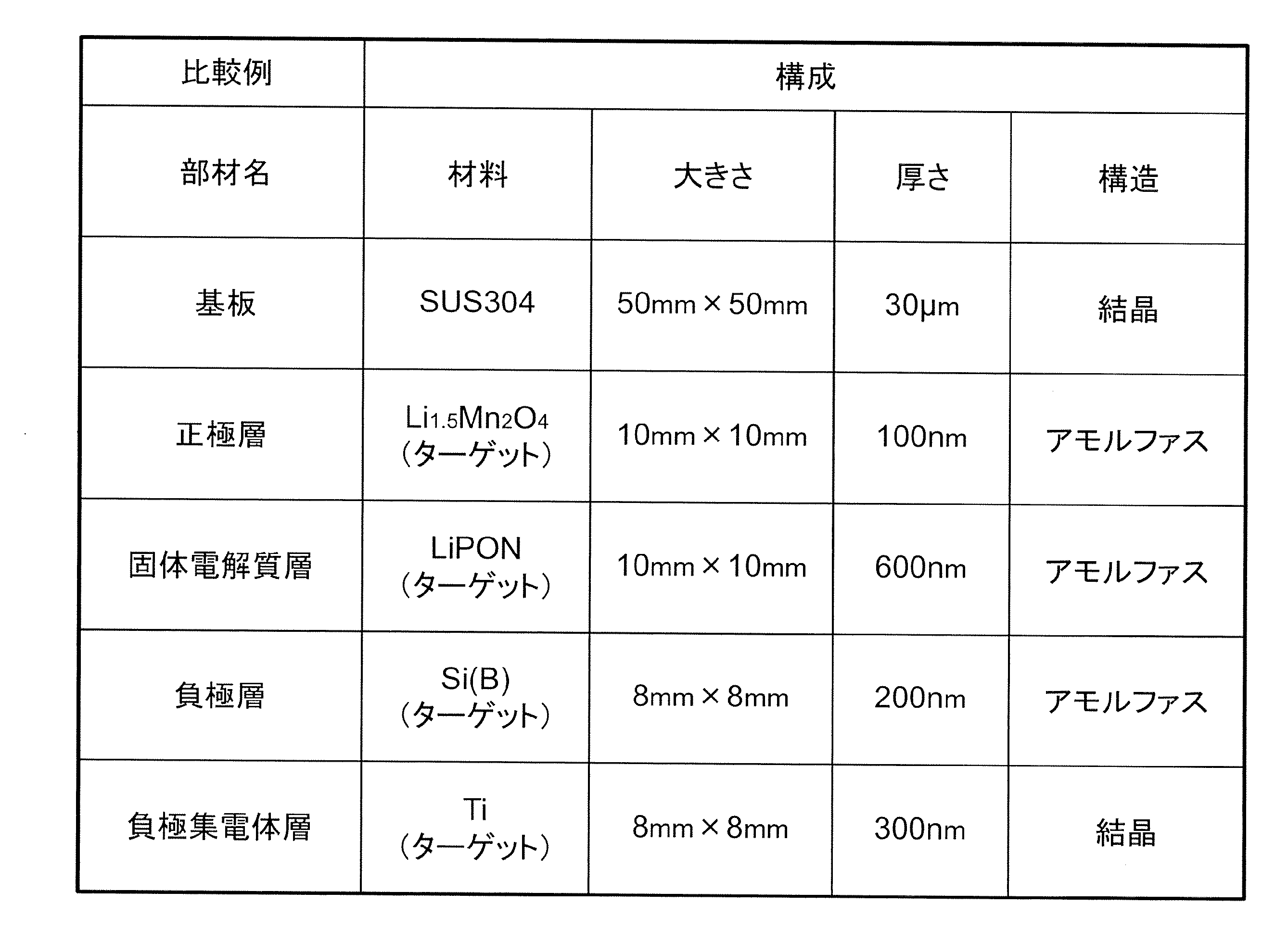
では、図4および表2を参照しつつ、比較例のリチウムイオン二次電池2の作製方法について説明を行う。
比較例でも、基板10としてSUS304を用いた。ここで、基板10の大きさ(50mm×50mm)および厚さ(30μm)は実施例と同じにした。
比較例では、スパッタ法を用いて、正極層40、固体電解質層30および負極層20の順に形成を行った。ここで、正極層40、固体電解質層30および負極層20のそれぞれの作製条件は、基本的に実施例と同じにした。
また、比較例では、スパッタ法を用いて、負極集電体層80の形成を行った。なお、負極集電体層80の作製条件は、基本的に実施例における正極集電体層50と同じにした。
ただし、比較例のリチウムイオン二次電池2の作製において、正極層40および固体電解質層30の大きさは10mm×10mmとし、負極層20および負極集電体層80の大きさは8mm×8mmとした。
比較例でも、基板10としてSUS304を用いた。ここで、基板10の大きさ(50mm×50mm)および厚さ(30μm)は実施例と同じにした。
比較例では、スパッタ法を用いて、正極層40、固体電解質層30および負極層20の順に形成を行った。ここで、正極層40、固体電解質層30および負極層20のそれぞれの作製条件は、基本的に実施例と同じにした。
また、比較例では、スパッタ法を用いて、負極集電体層80の形成を行った。なお、負極集電体層80の作製条件は、基本的に実施例における正極集電体層50と同じにした。
ただし、比較例のリチウムイオン二次電池2の作製において、正極層40および固体電解質層30の大きさは10mm×10mmとし、負極層20および負極集電体層80の大きさは8mm×8mmとした。
このようにして得られた比較例のリチウムイオン二次電池2に、X線回折(XRD)による解析を行った。その結果、基板10および負極集電体層80は結晶化していた。これに対し、正極層40、固体電解質層30および負極層20はアモルファス化していた。
[リチウムイオン二次電池の評価]
ここでは、実施例のリチウムイオン二次電池1および比較例のリチウムイオン二次電池2を評価するための尺度として、両者の断面構造と充放電特性とを用いた。
ここでは、実施例のリチウムイオン二次電池1および比較例のリチウムイオン二次電池2を評価するための尺度として、両者の断面構造と充放電特性とを用いた。
(断面構成)
図5は、実施例のリチウムイオン二次電池1の断面STEM(Scanning Transmission Electron Microscope)写真である。また、図6は、比較例のリチウムイオン二次電池2の断面STEM写真である。ここで、図5(a)の拡大倍率は6万倍であり、図5(b)の拡大倍率は10万倍である。また、図6の拡大倍率は図5(a)と同じ6万倍である。
図5は、実施例のリチウムイオン二次電池1の断面STEM(Scanning Transmission Electron Microscope)写真である。また、図6は、比較例のリチウムイオン二次電池2の断面STEM写真である。ここで、図5(a)の拡大倍率は6万倍であり、図5(b)の拡大倍率は10万倍である。また、図6の拡大倍率は図5(a)と同じ6万倍である。
これらのSTEM写真は、日立ハイテクノロジーズ社製HD-2300型超薄膜評価装置を用いて撮影した。ここで、STEMでは、組成情報を反映した像を得ることができるという特徴がある。より具体的に説明すると、STEMでは、重い元素が存在する領域は相対的に黒っぽく表示され、軽い元素が存在する領域は相対的に白っぽく表示される。なお、リチウムは、水素およびヘリウムの次に軽い元素であることから、図5および図6に示すSTEM写真においてリチウムが存在する領域は、白っぽく表示される。ここで、図5(a)および図6のそれぞれにおいて、最も上方に位置する領域が黒くなっているのは、STEM写真を撮影する際に各試料に付着させたW(タングステン)が見えているためである。
まず、図5を参照しつつ、実施例のリチウムイオン二次電池1の断面構造について説明を行う。
図5(a)に示すリチウムイオン二次電池1は、基板10と、負極層20と、固体電解質層30と、正極層40と、正極集電体層50とを、この順に積層した断面構造を有している。ただし、固体電解質層30と正極層40との境界部には、固体電解質層30および正極層40とは濃度の異なる層が存在していることがわかる。ここで、図5(b)の拡大写真を参照すると、固体電解質層30および正極層40との間に存在する層は、正極層40側に位置する濃度が均一な層と、固体電解質層30側に位置する濃度が不均一(まだら)な層とに分類することができる。これらのうち、濃度の均一な層が中間層60であり、濃度の不均一な層が混在層70である。そして、図5(b)より、中間層60は、固体電解質層30および正極層40の中間の濃度を呈していることがわかる。また、混在層70は、固体電解質層30と同濃度の母材と、母材中に分散された、正極層40と同濃度の粒子とを有していることがわかる。ただし、中間層60にも、正極層40と同濃度の粒子が存在している。なお、図5(b)に示すSTEM写真より、中間層60の厚さは30nm程度であった。また、混在層70の厚さは50nm程度であった。
図5(a)に示すリチウムイオン二次電池1は、基板10と、負極層20と、固体電解質層30と、正極層40と、正極集電体層50とを、この順に積層した断面構造を有している。ただし、固体電解質層30と正極層40との境界部には、固体電解質層30および正極層40とは濃度の異なる層が存在していることがわかる。ここで、図5(b)の拡大写真を参照すると、固体電解質層30および正極層40との間に存在する層は、正極層40側に位置する濃度が均一な層と、固体電解質層30側に位置する濃度が不均一(まだら)な層とに分類することができる。これらのうち、濃度の均一な層が中間層60であり、濃度の不均一な層が混在層70である。そして、図5(b)より、中間層60は、固体電解質層30および正極層40の中間の濃度を呈していることがわかる。また、混在層70は、固体電解質層30と同濃度の母材と、母材中に分散された、正極層40と同濃度の粒子とを有していることがわかる。ただし、中間層60にも、正極層40と同濃度の粒子が存在している。なお、図5(b)に示すSTEM写真より、中間層60の厚さは30nm程度であった。また、混在層70の厚さは50nm程度であった。
次に、上述した日立ハイテクノロジーズ社製HD-2300型超薄膜評価装置を用い、図5(a)に示すSTEM写真を撮影した領域に対し、元素マッピングによる評価を行った。ここでは、炭素(C)、チタン(Ti)、シリコン(Si)、リン(P)、窒素(N)、酸素(O)およびマンガン(Mn)の7種類の元素について解析を行った。
炭素(C)に関する元素マッピングを行ったところ、基板10において相対的な濃度が高くなり、その他では相対的な濃度が低くなった。これは、基板10を構成するSUS304が、炭素を含んでいることに起因する。
チタン(Ti)に関する元素マッピングを行ったところ、正極集電体層50において相対的な濃度が高くなり、その他では相対的な濃度が低くなった。これは、正極集電体層50が、チタンで構成されていることに起因する。
シリコン(Si)に関する元素マッピングを行ったところ、負極層20において相対的な濃度が高くなり、その他では相対的な濃度が低くなった。これは、負極層20が、シリコンを主成分として構成されていることに起因する。
リン(P)に関する元素マッピングを行ったところ、固体電解質層30、中間層60および混在層70において相対的な濃度が高くなり、その他では相対的な濃度が低くなった。これは、固体電解質層30を構成するLiPONが、リンを含んでいることに起因する。また、この結果から、中間層60および混在層70の両者が、リンを含んでいることが明らかとなった。
窒素(N)に関する元素マッピングを行ったところ、固体電解質層30、中間層60および混在層70において相対的な濃度が高くなり、その他では相対的な濃度が低くなった。これは、固体電解質層30を構成するLiPONが、窒素を含んでいることに起因する。また、この結果から、中間層60および混在層70の両者が、窒素を含んでいることが明らかとなった。
酸素(O)に関する元素マッピングを行ったところ、固体電解質層30、正極層40、中間層60および混在層70において相対的な濃度が高くなり、その他では相対的な濃度が低くなった。これは、固体電解質層30を構成するLiPONおよび正極層40を構成するLi1.5Mn2O4が、酸素を含んでいることに起因する。また、この結果から、中間層60および混在層70の両者が、酸素を含んでいることが明らかとなった。
マンガン(Mn)に関する元素マッピングを行ったところ、正極層40、中間層60および混在層70において相対的な濃度が高くなり、その他では相対的な濃度が低くなった。これは、正極層40を構成するLi1.5Mn2O4が、マンガンを含んでいることに起因する。また、この結果から、中間層60および混在層70の両者が、マンガンを含んでいることが明らかとなった。
以上の元素マッピングの結果から、中間層60および混在層70は、固体電解質層30の構成材料(リチウム、リン、酸素および窒素)と、正極層40の構成材料(リチウム、マンガンおよび酸素)とを含んでいることが明らかとなった。
そして、図5に示すSTEM写真において、均一の濃度を呈している中間層60では、これらリチウム、リン、酸素および窒素が、化合物となった状態で存在していることが示唆される。また、図5に示すSTEM写真において、不均一の濃度を呈している混在層70では、LiPONからなるマトリックスに、Li1.5Mn2O4からなるフィラーが分散した状態で存在していることが示唆される。
また、実施例のリチウムイオン二次電池1の正極層40におけるマンガン(Mn)の価数を、EELS(Electron Energy Loss Spectroscopy)により解析したところ、2価であることがわかった。
続いて、図6を参照しつつ、比較例のリチウムイオン二次電池2の断面構造について説明を行う。
図6に示すリチウムイオン二次電池2は、基板10と、正極層40と、固体電解質層30と、負極層20と、負極集電体層80とを、この順に積層した断面構造を有している。ただし、このリチウムイオン二次電池2における正極層40と固体電解質層30との境界部には、実施例のリチウムイオン二次電池1のような、中間層60や混在層70は存在していない。
図6に示すリチウムイオン二次電池2は、基板10と、正極層40と、固体電解質層30と、負極層20と、負極集電体層80とを、この順に積層した断面構造を有している。ただし、このリチウムイオン二次電池2における正極層40と固体電解質層30との境界部には、実施例のリチウムイオン二次電池1のような、中間層60や混在層70は存在していない。
次に、上述した日立ハイテクノロジーズ社製HD-2300型超薄膜評価装置を用い、図6に示すSTEM写真を撮影した領域に対し、元素マッピングによる評価を行った。ここでは、上記実施例と同じく、炭素(C)、チタン(Ti)、シリコン(Si)、リン(P)、窒素(N)、酸素(O)およびマンガン(Mn)の7種類の元素について解析を行った。
その結果、中間層60や混在層70が存在していない点を除き、炭素(C)、チタン(Ti)、シリコン(Si)、リン(P)、窒素(N)、酸素(O)およびマンガン(Mn)のそれぞれについて、実施例と同等の結果が得られた。
また、比較例のリチウムイオン二次電池2の正極層40におけるマンガン(Mn)の価数を、EELSにより解析したところ、実施例のリチウムイオン二次電池1と同じ2価であることがわかった。
なお、中間層60および混在層70が、実施例のリチウムイオン二次電池1には形成されるのに対し、比較例のリチウムイオン二次電池2には形成されないのは、次の理由によるものと推定される。
実施例および比較例では、固体電解質層30を構成する無機固体電解質としてLiPONを用いる一方、正極層40を構成する正極活物質としてLi1.5Mn2O4を用いている。そして、Li1.5Mn2O4を構成する各元素のうち最も重い元素となるマンガン(Mn)は、LiPONを構成する各元素のうち最も重い元素となるリン(P)よりも重い。
実施例では、固体電解質層30上に、スパッタ法を用いて、正極層40を形成している。このため、既に積層されている固体電解質層30に対し、正極活物質を構成する各元素を衝突させた際に、マンガンを含む正極活物質が、固体電解質層30内に侵入しやすくなる。その結果、固体電解質層30と正極層40との間に、中間層60および混在層70が形成されるものと考えられる。
これに対し、比較例では、正極層40上に、スパッタ法を用いて、固体電解質層30を形成している。このため、既に積層されている正極層40に対し、無機固体電解質を構成する各元素を衝突させた際に、リンを含む無機固体電解質が、正極層40内に侵入しにくくなる。その結果、固体電解質層30と正極層40との間に、中間層60および混在層70が形成されにくいものと考えられる。
(充放電特性)
実施例のリチウムイオン二次電池1および比較例のリチウムイオン二次電池2のそれぞれに対して、充放電特性の測定を行った。充放電特性の測定機器としては、北斗電工株式会社製 充放電装置HJ1020mSD8を用いた。ここでは、充電時の電流(充電電流)および放電時の電流(放電電流)を、それぞれ、10μA、20μAおよび40μAとした。
実施例のリチウムイオン二次電池1および比較例のリチウムイオン二次電池2のそれぞれに対して、充放電特性の測定を行った。充放電特性の測定機器としては、北斗電工株式会社製 充放電装置HJ1020mSD8を用いた。ここでは、充電時の電流(充電電流)および放電時の電流(放電電流)を、それぞれ、10μA、20μAおよび40μAとした。
図7(a)は実施例のリチウムイオン二次電池1の充放電特性を示す図である。また図7(b)は、比較例のリチウムイオン二次電池2の充放電特性を示す図である。ここで、図7(a)、(b)のそれぞれにおいて、横軸は電池容量(μAh)であり、縦軸は電池電圧(V)である。また、図7(a)、(b)のそれぞれにおいて、図中右上がりとなっているのが充電特性であり、図中右下がりとなっているのが放電特性である。
実施例のリチウムイオン二次電池1および比較例のリチウムイオン二次電池2において、負極層20、固体電解質層30および正極層40は、同一材料且つ同一厚さで構成されている。しかしながら、図7(a)、(b)からも明らかなように、比較例のリチウムイオン二次電池2は、実施例のリチウムイオン二次電池1に比べて、電池電圧の上昇が急峻となっている。その結果、比較例のリチウムイオン二次電池2は、実施例のリチウムイオン二次電池1に比べて、充電完了時の電池容量が少なくなっている。また、比較例のリチウムイオン二次電池2は、実施例のリチウムイオン二次電池1に比べて、放電時の電池電圧の低下が急峻となっている。このように、実施例のリチウムイオン二次電池1は、比較例のリチウムイオン二次電池2と比べて、電池容量すなわち充電容量および放電容量が増加していることがわかる。
このような違いは、実施例のリチウムイオン二次電池1が、比較例のリチウムイオン二次電池2よりも内部抵抗が低下していることに起因するものと考えられる。そして、実施例のリチウムイオン二次電池1は、固体電解質層30と正極層40との境界部に混在層70等が設けられていることから、混在層70等を有しない比較例のリチウムイオン二次電池2に比べて、内部抵抗が低下するものと考えられる。
1、2…リチウムイオン二次電池、10…基板、20…負極層、30…固体電解質層、40…正極層、50…正極集電体層、60…中間層、70…混在層、80…負極集電体層
Claims (8)
- 正極活物質を含む正極層と、
負極活物質を含む負極層と、
リチウムイオン伝導性を示す無機固体電解質を含み且つ前記正極層と前記負極層との間に設けられる固体電解質層と、
前記正極活物質と前記無機固体電解質とが混在し、前記正極層と前記固体電解質層との間に設けられる混在層と
を有するリチウムイオン二次電池。 - 前記正極活物質は、前記無機固体電解質よりも重い元素を含んでいることを特徴とする請求項1記載のリチウムイオン二次電池。
- 前記混在層では、前記無機固体電解質からなる母材に、前記正極活物質からなる粒子が分散していることを特徴とする請求項1または2記載のリチウムイオン二次電池。
- 前記正極層と前記混在層との境界部には、前記正極活物質の構成材料と前記無機固体電解質の構成材料とを含み、さらに当該正極活物質が混在する中間層が設けられることを特徴とする請求項1乃至3のいずれか1項記載のリチウムイオン二次電池。
- 前記負極層、前記中間層および前記正極層を、この順で積層する基板をさらに有することを特徴とする請求項1乃至4のいずれか1項記載のリチウムイオン二次電池。
- 負極活物質を含む負極層を形成する負極層形成工程と、
前記負極層の上に、リチウムイオン伝導性を示す無機固体電解質を含む固体電解質層を形成する固体電解質層形成工程と、
前記固体電解質層の上に、正極活物質と前記無機固体電解質とが混在する混在層を形成するとともに、当該混在層の上に、当該正極活物質を含む正極層を形成する正極層形成工程と
を有するリチウムイオン二次電池の製造方法。 - 前記正極層形成工程では、スパッタ法にて前記混在層および前記正極層を形成し、
前記正極活物質は、前記無機固体電解質よりも重い元素を含んでいることを特徴とする請求項6記載のリチウムイオン二次電池の製造方法。 - 前記正極層形成工程では、前記混在層の上に、前記正極活物質の構成材料と前記無機固体電解質の構成材料とを含み、さらに当該正極活物質が混在する中間層をさらに形成することを特徴とする請求項6または7記載のリチウムイオン二次電池の製造方法。
Priority Applications (2)
| Application Number | Priority Date | Filing Date | Title |
|---|---|---|---|
| US16/498,606 US20210194040A1 (en) | 2017-04-14 | 2018-01-19 | Lithium-ion rechargeable battery and method for manufacturing lithium-ion rechargeable battery |
| CN201880019310.4A CN110431705A (zh) | 2017-04-14 | 2018-01-19 | 锂离子二次电池和锂离子二次电池的制造方法 |
Applications Claiming Priority (2)
| Application Number | Priority Date | Filing Date | Title |
|---|---|---|---|
| JP2017-080642 | 2017-04-14 | ||
| JP2017080642A JP2018181636A (ja) | 2017-04-14 | 2017-04-14 | リチウムイオン二次電池およびリチウムイオン二次電池の製造方法 |
Publications (1)
| Publication Number | Publication Date |
|---|---|
| WO2018189976A1 true WO2018189976A1 (ja) | 2018-10-18 |
Family
ID=63792454
Family Applications (1)
| Application Number | Title | Priority Date | Filing Date |
|---|---|---|---|
| PCT/JP2018/001569 Ceased WO2018189976A1 (ja) | 2017-04-14 | 2018-01-19 | リチウムイオン二次電池およびリチウムイオン二次電池の製造方法 |
Country Status (4)
| Country | Link |
|---|---|
| US (1) | US20210194040A1 (ja) |
| JP (1) | JP2018181636A (ja) |
| CN (1) | CN110431705A (ja) |
| WO (1) | WO2018189976A1 (ja) |
Families Citing this family (3)
| Publication number | Priority date | Publication date | Assignee | Title |
|---|---|---|---|---|
| JP2020105600A (ja) * | 2018-12-28 | 2020-07-09 | 昭和電工株式会社 | スパッタリングターゲット |
| JP2020107531A (ja) * | 2018-12-28 | 2020-07-09 | 昭和電工株式会社 | リチウムイオン二次電池の製造方法 |
| CN116682960A (zh) * | 2022-02-22 | 2023-09-01 | 南京理工大学 | 透明全固态薄膜锂离子电池及其制备方法 |
Citations (5)
| Publication number | Priority date | Publication date | Assignee | Title |
|---|---|---|---|---|
| JPH10284130A (ja) * | 1997-04-04 | 1998-10-23 | Nec Corp | 半導体基板搭載型二次電池 |
| JP2001126758A (ja) * | 1999-10-28 | 2001-05-11 | Kyocera Corp | リチウム電池 |
| JP2007335206A (ja) * | 2006-06-14 | 2007-12-27 | Nissan Motor Co Ltd | 双極型電池 |
| JP2009054596A (ja) * | 2008-10-30 | 2009-03-12 | Ohara Inc | リチウムイオン二次電池及びその製造方法 |
| JP2013073846A (ja) * | 2011-09-28 | 2013-04-22 | Sony Corp | リチウムイオン二次電池 |
-
2017
- 2017-04-14 JP JP2017080642A patent/JP2018181636A/ja not_active Withdrawn
-
2018
- 2018-01-19 US US16/498,606 patent/US20210194040A1/en not_active Abandoned
- 2018-01-19 WO PCT/JP2018/001569 patent/WO2018189976A1/ja not_active Ceased
- 2018-01-19 CN CN201880019310.4A patent/CN110431705A/zh not_active Withdrawn
Patent Citations (5)
| Publication number | Priority date | Publication date | Assignee | Title |
|---|---|---|---|---|
| JPH10284130A (ja) * | 1997-04-04 | 1998-10-23 | Nec Corp | 半導体基板搭載型二次電池 |
| JP2001126758A (ja) * | 1999-10-28 | 2001-05-11 | Kyocera Corp | リチウム電池 |
| JP2007335206A (ja) * | 2006-06-14 | 2007-12-27 | Nissan Motor Co Ltd | 双極型電池 |
| JP2009054596A (ja) * | 2008-10-30 | 2009-03-12 | Ohara Inc | リチウムイオン二次電池及びその製造方法 |
| JP2013073846A (ja) * | 2011-09-28 | 2013-04-22 | Sony Corp | リチウムイオン二次電池 |
Also Published As
| Publication number | Publication date |
|---|---|
| CN110431705A (zh) | 2019-11-08 |
| US20210194040A1 (en) | 2021-06-24 |
| JP2018181636A (ja) | 2018-11-15 |
Similar Documents
| Publication | Publication Date | Title |
|---|---|---|
| JP4460642B2 (ja) | リチウム二次電池用負極およびその製造方法、ならびにリチウム二次電池用負極を備えたリチウム二次電池 | |
| JP5151692B2 (ja) | リチウム電池 | |
| JP2018110098A (ja) | 電池 | |
| JP2014107163A (ja) | 全固体リチウム二次電池の製造方法 | |
| WO2011043267A1 (ja) | 非水電解質電池 | |
| JPWO2011128978A1 (ja) | 固体電解質材料、リチウム電池および固体電解質材料の製造方法 | |
| JP4329357B2 (ja) | リチウム二次電池負極部材、及びその製造方法 | |
| WO2018189976A1 (ja) | リチウムイオン二次電池およびリチウムイオン二次電池の製造方法 | |
| JP7034703B2 (ja) | リチウムイオン二次電池 | |
| JP2018116892A (ja) | リチウムイオン二次電池、正極活物質 | |
| JP2019114529A (ja) | リチウムイオン二次電池 | |
| KR101484845B1 (ko) | 리튬 이온 이동로가 구비된 고체 전해질을 포함하는 이차전지, 및 그의 제조방법 | |
| US20230268518A1 (en) | High surface area electrode for solid-state battery | |
| JP5521719B2 (ja) | 全固体二次電池用集電体、全固体二次電池用電極体および全固体二次電池 | |
| JP7034704B2 (ja) | リチウムイオン二次電池の製造方法 | |
| WO2019039100A1 (ja) | リチウムイオン二次電池、リチウムイオン二次電池の正極 | |
| WO2019077825A1 (ja) | リチウムイオン二次電池の製造方法、リチウムイオン二次電池 | |
| JP3984937B2 (ja) | リチウム二次電池用負極の製造に用いる成膜用材料、リチウム二次電池用負極の製造方法及びリチウム二次電池用負極 | |
| JP5187502B2 (ja) | リチウム電池 | |
| WO2020137618A1 (ja) | リチウムイオン二次電池の製造方法 | |
| WO2020137616A1 (ja) | リチウムイオン二次電池、リチウムイオン二次電池の正極 | |
| US20250167247A1 (en) | Method for manufacturing lithium secondary battery | |
| JP2009218125A (ja) | リチウム電池 | |
| JP2010140703A (ja) | 非水電解質電池 | |
| US20220190347A1 (en) | Anode for All-Solid-State Battery Comprising Metal-Thin-Film Coating Layer and Method of Manufacturing Same |
Legal Events
| Date | Code | Title | Description |
|---|---|---|---|
| 121 | Ep: the epo has been informed by wipo that ep was designated in this application |
Ref document number: 18784606 Country of ref document: EP Kind code of ref document: A1 |
|
| NENP | Non-entry into the national phase |
Ref country code: DE |
|
| 122 | Ep: pct application non-entry in european phase |
Ref document number: 18784606 Country of ref document: EP Kind code of ref document: A1 |